DIGITAL FILMMAKING CAMERA
FF250002
Owner’s Manual
BL00005410-202
EN

ii
Introduction
Thank you for your purchase of this product. Be sure that
you have read this manual and understood its contents be-
fore using the camera. Keep the manual where it will be
read by all who use the product.
For the Latest Information
The latest versions of the manuals are available from:
https://fujifilm-dsc.com/en/manual/
The website can be accessed not only from
your computer but also from smartphones
and tablets. It also contains information on the
software license.
For information on rmware updates, visit:
https://fujifilm-x.com/support/download/firmware/cameras/

iii
P
Chapter Index
1 Before You Begin 1
2 First Steps 31
3 Basic Shooting and Playback 61
4 Shooting Settings 69
5 Playback and the Playback Menu 89
6 Network Connection 97
7 The Menus 117
8 Shortcuts 179
9 Peripherals and Optional Accessories 189
10 Technical Notes 203
Menu List
iv

iv
Menu List
Menu List
Camera menu options are listed below.
HOME
This menu is assigned to the screen buttons on the HOME display.
HOME
P
Recording frame rate
Recording frame rate 70
ISO sensitivity
ISO sensitivity 71
Shutter
Shutter 72
ND lter
ND lter 73
Look
Look 74
White balance
White balance 76
USER
This menu is assigned to the screen buttons on the USER display.
USER
P
USER1
USER1
187
USER2
USER2
USER3
USER3
USER4
USER4
USER5
USER5
USER6
USER6
PLAY
This menu is displayed when you press SETTING (Screen but-
ton5) on the PLAY display.
PLAY
P
SDI/HDMI OUTPUT SETTING
SDI/HDMI OUTPUT SETTING 95
VOLUME
VOLUME 96
4ch AUDIO PLAYBACK
4ch AUDIO PLAYBACK 96
DESQUEEZE DISP. IN PLAYBACK
DESQUEEZE DISP. IN PLAYBACK 96

v
Menu List
Menu List
MENU
These menus are displayed when you press MENU.
PROJECT
P
IMAGE FORMAT
IMAGE FORMAT 118
RESOLUTION
RESOLUTION 119
PROJECT FPS
PROJECT FPS 119
F-Log/HLG/RAW
F-Log/HLG/RAW 120
FILM SIMULATION
FILM SIMULATION 122
LUT SETTING
LUT SETTING 124
MEDIA REC SETTING
MEDIA REC SETTING 124
CLIP SETTING
CLIP SETTING 126
RECORDING
P
IRIS
IRIS 127
IRIS DISP
IRIS DISP 127
EXP. COMPENSATION
EXP. COMPENSATION 127
PHOTOMETRY
PHOTOMETRY 127
SELF-TIMER
SELF-TIMER 128
IS SETTING
IS SETTING 128
PERIPHERAL ILLUMINATION
PERIPHERAL ILLUMINATION
CORRECTION
CORRECTION
129
MOUNT ADAPTOR SETTING
MOUNT ADAPTOR SETTING 129
GENLOCK
GENLOCK 130
IMAGE QUALITY
P
TONE CURVE
TONE CURVE 131
COLOR
COLOR 131
SHARPNESS
SHARPNESS 131
NOISE REDUCTION
NOISE REDUCTION 132
INTERFRAME NR
INTERFRAME NR 132
MONOCHROMATIC COLOR
MONOCHROMATIC COLOR 133
F-Log2/ C D RANGE PRIORITY
F-Log2/ C D RANGE PRIORITY 133
FOCUS
P
AF MODE
AF MODE 134
FOCUS AREA
FOCUS AREA 134
ROTATE FOCUS POINT
ROTATE FOCUS POINT 134
AF-C CUSTOM SETTINGS
AF-C CUSTOM SETTINGS 135
SUBJECT DETECTION SETTING
SUBJECT DETECTION SETTING 136
AF+MF
AF+MF 138
INSTANT AF SETTING
INSTANT AF SETTING 138
AF RANGE LIMITER
AF RANGE LIMITER 138
FOCUS CHECK
FOCUS CHECK 140
FOCUS CHECK LOCK
FOCUS CHECK LOCK 140
TOUCH SCREEN MODE
TOUCH SCREEN MODE 141
AUDIO SETTING
P
INT MIC LEVEL ADJUSTMENT
INT MIC LEVEL ADJUSTMENT 142
EXT MIC LEVEL ADJUSTMENT
EXT MIC LEVEL ADJUSTMENT 142
MIC JACK SETTING
MIC JACK SETTING 143
MIC LEVEL LIMITER
MIC LEVEL LIMITER 143
WIND FILTER
WIND FILTER 143
LOW CUT FILTER
LOW CUT FILTER 144
HEADPHONES VOLUME
HEADPHONES VOLUME 144
XLR MIC ADAPTER SETTING
XLR MIC ADAPTER SETTING 144
TIME CODE SETTING
P
START TIME SETTING
START TIME SETTING 146
COUNT UP SETTING
COUNT UP SETTING 146
DROP FRAME
DROP FRAME 146
SDI/HDMI TIME CODE OUTPUT
SDI/HDMI TIME CODE OUTPUT 146
TIME CODE CONNECTOR
TIME CODE CONNECTOR 147
TIME CODE SYNC. SETTING
TIME CODE SYNC. SETTING 147

vi
Menu List
MONITOR SETTING
P
SDI/HDMI OUTPUT SETTING
SDI/HDMI OUTPUT SETTING 148
WAVEFORM/VECTORSCOPE
WAVEFORM/VECTORSCOPE 151
FOCUS PEAK HIGHLIGHT
FOCUS PEAK HIGHLIGHT 152
ZEBRA SETTING
ZEBRA SETTING 153
FRAMING GUIDELINE
FRAMING GUIDELINE 153
ELECTRONIC LEVEL SETTING
ELECTRONIC LEVEL SETTING 157
REC FRAME
REC FRAME 157
DISP. CUSTOM SETTING
DISP. CUSTOM SETTING 158
FOCUS SCALE UNITS
FOCUS SCALE UNITS 159
LCD INVERSION SETTING
LCD INVERSION SETTING 159
USER
P
Fn SETTING
Fn SETTING 160
ZOOM/FOCUS SETTING
ZOOM/FOCUS SETTING 160
FOCUS LEVER SETTING
FOCUS LEVER SETTING 162
TOUCH SCREEN SETTING
TOUCH SCREEN SETTING 162
NETWORK
P
WIRELESS LAN
WIRELESS LAN 164
WIRED LAN SETTING
WIRED LAN SETTING 164
Frame.io Camera to Cloud
Frame.io Camera to Cloud 165
REMOTE REC FUNCTION
REMOTE REC FUNCTION 168
Bluetooth SETTING
Bluetooth SETTING 169
ERROR DESCRIPTION
ERROR DESCRIPTION 170
HARDWARE INFO
HARDWARE INFO 170
RESET NETWORK SETTING
RESET NETWORK SETTING 170
SET UP
P
Q
Q
a
a
171
DATE/TIME
DATE/TIME 171
RESET ALL EXCEPT NETWORK
RESET ALL EXCEPT NETWORK
SETTINGS
SETTINGS
172
FORMAT
FORMAT 172
MAINTENANCE
MAINTENANCE 173
COOLING FAN SETTING
COOLING FAN SETTING 174
POWER MANAGEMENT
POWER MANAGEMENT 175
LED/SOUND SETTING
LED/SOUND SETTING 176
LCD SETTING
LCD SETTING 177
FIRMWARE UPDATE
FIRMWARE UPDATE 178
REGULATORY
REGULATORY 178

vii
P
Table of Contents
Introduction .......................................................................................................... ii
For the Latest Information .......................................................................................... ii
Menu List ...............................................................................................................iv
HOME .....................................................................................................................................iv
USER ........................................................................................................................................iv
PLAY .........................................................................................................................................iv
MENU ....................................................................................................................................... v
Supplied Accessories ..................................................................................... xvi
About This Manual ......................................................................................... xvii
Symbols and Conventions .................................................................................... xvii
Terminology ................................................................................................................... xvii
1
Before You Begin 1
Before You Begin 1
Parts of the Camera ............................................................................................2
Camera Body.......................................................................................................................2
LCD Monitor ........................................................................................................................6
Handle .....................................................................................................................................7
Side Monitors......................................................................................................................8
REC Button ..........................................................................................................................13
GRAB Button ......................................................................................................................13
Focus Mode Selector .................................................................................................. 13
Multi-Function Dial ......................................................................................................14
Lock Switch ....................................................................................................................... 15
The Indicator Lamp ......................................................................................................16
Accessory Mounting Screw Holes/
Tripod Plate Attachment Holes .........................................................................17
LCD Cable Connector Cover (Detachable)....................................................19
Measure Hook .................................................................................................................20
Air Intakes/Exhaust Vent ........................................................................................... 20
Wi-Fi Antenna (Internal) ............................................................................................ 21
Handle ..................................................................................................................................21
LCD Monitor .....................................................................................................................23
The Serial Number Plates ......................................................................................... 25

viii
Camera Displays ............................................................................................... 26
LCD Monitor Display ................................................................................................... 26
Side Monitor Display ................................................................................................... 28
2
First Steps 31
First Steps 31
Charging the Supplied Battery ...................................................................32
Charging the Supplied Battery ............................................................................. 32
Using the AC Power Adapter ....................................................................... 37
Inserting Memory Cards ................................................................................ 39
Using Two Cards ............................................................................................................41
Compatible Memory Cards .................................................................................... 42
Using an External SSD in Place of a Memory Card ................................... 44
Attaching a Lens ............................................................................................... 45
G-mount Lenses ............................................................................................................45
PL-mount Lenses ........................................................................................................... 47
Attaching the Handle .....................................................................................52
Attaching the LCD Monitor ..........................................................................54
Turning the Camera On and O .................................................................56
Checking the Supplied Battery Level ........................................................57
Basic Setup .........................................................................................................58
Choosing a Di erent Language ...........................................................................60
Changing the Time and Date ................................................................................ 60
3
Basic Shooting and Playback 61
Basic Shooting and Playback 61
Recording Movies ............................................................................................62
Viewing Movies .................................................................................................64
Saving Still Images ........................................................................................... 66
Playing Saved Still Images ............................................................................67

ix
Table of Contents
4
Shooting Settings 69
Shooting Settings 69
Recording Frame Rate ....................................................................................70
ISO Sensitivity .................................................................................................... 71
Shutter .................................................................................................................72
ND Filter ............................................................................................................... 73
Using ND Filter ................................................................................................................73
Look ......................................................................................................................74
Setting LUTs ...................................................................................................................... 74
Applying to Footage ................................................................................................... 75
White Balance ....................................................................................................76
Auto White Balance ..................................................................................................... 76
Custom White Balance............................................................................................... 77
Preset White Balance...................................................................................................78
Autofocus ............................................................................................................80
AF MODE ............................................................................................................................ 80
FOCUS AREA .................................................................................................................... 81
Manual Focus .....................................................................................................82
Focus Ring ......................................................................................................................... 82
Multi-Function Dial/Function Buttons ............................................................. 82
Iris ..........................................................................................................................83
Aperture Ring ..................................................................................................................83
Recording Setting ......................................................................................................... 83
Multi-Function Dial ......................................................................................................83
Function Buttons ........................................................................................................... 83
Zoom ....................................................................................................................84
Zoom Ring ......................................................................................................................... 84
Power Zoom .....................................................................................................................84
Photometry ........................................................................................................ 85
Touch Screen Mode .........................................................................................86
LCD Monitor Touch Controls .................................................................................. 86
Selecting a Focus Area ...............................................................................................87
Focus Zoom ......................................................................................................................87

x
5
Playback and the Playback Menu 89
Playback and the Playback Menu 89
The Playback Display ......................................................................................90
Side Monitors...................................................................................................................90
LCD Monitor .....................................................................................................................92
The Playback Menu .........................................................................................95
SDI/HDMI OUTPUT SETTING .................................................................................. 95
VOLUME ..............................................................................................................................96
4ch AUDIO PLAYBACK ................................................................................................ 96
DESQUEEZE DISP. IN PLAYBACK ........................................................................... 96
6
Network Connection 97
Network Connection 97
Overview ............................................................................................................. 98
Supported Features ..................................................................................................... 98
Connecting to the Network .........................................................................99
Connecting via Wireless LAN ................................................................................. 99
Connecting via Wired LAN ................................................................................... 102
Uploading Files to Frame.io ........................................................................103
Connecting to Frame.io ......................................................................................... 103
Uploading Files to Frame.io ................................................................................. 104
Remote Movie Recording Using a Web Browser ................................105
Con guring the Camera Settings .................................................................... 106
Connecting to the Camera from a Computer or Tablet .................... 107
The Remote Recording Display ......................................................................... 110
Recording Movies Remotely ............................................................................... 114
Viewing Movies ........................................................................................................... 114
Saving and Loading Camera Settings ........................................................... 115
7
The Menus 117
The Menus 117
PROJECT ............................................................................................................118
IMAGE FORMAT ........................................................................................................... 118
RESOLUTION .................................................................................................................. 119
PROJECT FPS ................................................................................................................. 119
F-Log/HLG/RAW .......................................................................................................... 120
FILM SIMULATION ...................................................................................................... 122

xi
Table of Contents
LUT SETTING .................................................................................................................. 124
MEDIA REC SETTING ................................................................................................. 124
CLIP SETTING ................................................................................................................ 126
RECORDING ......................................................................................................127
IRIS ....................................................................................................................................... 127
IRIS DISP ........................................................................................................................... 127
EXP. COMPENSATION ............................................................................................... 127
PHOTOME TRY ............................................................................................................... 127
SELF-TIMER ..................................................................................................................... 128
IS SETTING ...................................................................................................................... 128
PERIPHERAL ILLUMINATION CORRECTION ................................................. 129
MOUNT ADAPTOR SETTING ................................................................................ 129
GENLOCK ......................................................................................................................... 130
IMAGE QUALITY ..............................................................................................131
TONE CURVE.................................................................................................................. 131
COLOR ............................................................................................................................... 131
SHARPNESS .................................................................................................................... 131
NOISE REDUCTION .................................................................................................... 132
INTERFRAME NR .......................................................................................................... 132
MONOCHROMATIC COLOR .................................................................................. 133
F-Log2/ C D RANGE PRIORITY ............................................................................ 133
FOCUS ................................................................................................................134
AF MODE ......................................................................................................................... 134
FOCUS AREA ................................................................................................................. 134
ROTATE FOCUS POINT ............................................................................................. 134
AF-C CUSTOM SETTINGS ....................................................................................... 135
SUBJECT DETECTION SETTING .......................................................................... 136
AF+MF .............................................................................................................................. 138
INSTANT AF SETTING ............................................................................................... 138
AF RANGE LIMITER ..................................................................................................... 138
FOCUS CHECK .............................................................................................................. 140
FOCUS CHECK LOCK ................................................................................................ 140
TOUCH SCREEN MODE ........................................................................................... 141

xii
AUDIO SETTING ..............................................................................................142
INT MIC LEVEL ADJUSTMENT .............................................................................. 142
EXT MIC LEVEL ADJUSTMENT ............................................................................. 142
MIC JACK SETTING ..................................................................................................... 143
MIC LEVEL LIMITER .................................................................................................... 143
WIND FILTER .................................................................................................................. 143
LOW CUT FILTER .......................................................................................................... 144
HEADPHONES VOLUME ......................................................................................... 144
XLR MIC ADAPTER SETTING ................................................................................. 144
TIME CODE SETTING .....................................................................................146
START TIME SETTING ................................................................................................ 146
COUNT UP SETTING.................................................................................................. 146
DROP FRAME ................................................................................................................ 146
SDI/HDMI TIME CODE OUTPUT ......................................................................... 146
TIME CODE CONNECTOR ...................................................................................... 147
TIME CODE SYNC. SETTING .................................................................................. 147
MONITOR SETTING ........................................................................................148
SDI/HDMI OUTPUT SETTING ............................................................................... 148
WAVEFORM/VECTORSCOPE ................................................................................ 151
FOCUS PEAK HIGHLIGHT ....................................................................................... 152
ZEBRA SETTING ........................................................................................................... 153
FRAMING GUIDELINE ............................................................................................... 153
ELECTRONIC LEVEL SETTING .............................................................................. 157
REC FRAME ..................................................................................................................... 157
DISP. CUSTOM SETTING .......................................................................................... 158
FOCUS SCALE UNITS ................................................................................................ 159
LCD INVERSION SETTING ....................................................................................... 159
USER ....................................................................................................................160
Fn SETTING ..................................................................................................................... 160
ZOOM/FOCUS SETTING ......................................................................................... 160
FOCUS LEVER SETTING ........................................................................................... 162
TOUCH SCREEN SETTING ...................................................................................... 162

xiii
Table of Contents
NETWORK .........................................................................................................164
WIRELESS LAN .............................................................................................................. 164
WIRED LAN SETTING ................................................................................................ 164
Frame.io Camera to Cloud .................................................................................... 165
REMOTE REC FUNCTION ........................................................................................ 168
Bluetooth SETTING .................................................................................................... 169
ERROR DESCRIPTION ................................................................................................ 170
HARDWARE INFO ....................................................................................................... 170
RESET NETWORK SETTING ................................................................................... 170
SET UP ................................................................................................................171
Qa ............................................................................................................... 171
DATE/TIME ...................................................................................................................... 171
RESET ALL EXCEPT NETWORK SETTINGS ..................................................... 172
FORMAT ............................................................................................................................ 172
MAINTENANCE ............................................................................................................ 173
COOLING FAN SETTING .......................................................................................... 174
POWER MANAGEMENT .......................................................................................... 175
LED/SOUND SETTING .............................................................................................. 176
LCD SETTING ................................................................................................................. 177
FIRMWARE UPDATE ................................................................................................... 178
REGULATORY ................................................................................................................. 178
8
Shortcuts 179
Shortcuts 179
Shortcut Options ............................................................................................180
Function Controls...........................................................................................181
The Function Buttons .............................................................................................. 181
USER Function .................................................................................................187
Assigning Roles to the Screen Buttons......................................................... 188

xiv
9
Peripherals and Optional Accessories 189
Peripherals and Optional Accessories 189
Lenses .................................................................................................................190
Lens Parts ........................................................................................................................ 190
PL-Mount Adapter .........................................................................................192
Replacing the Shim on the PL-Mount Adapter ....................................... 192
Maximum Dimensions of PL-mount Lenses ............................................. 195
Connecting to External Devices ...............................................................196
12-pin Connector for Lens Connection ....................................................... 196
SDI OUT Connector (BNC Type) ........................................................................ 196
HDMI OUT Connector (Type A) ......................................................................... 196
TC IN/TC OUT Connector (BNC Type) ............................................................ 196
LAN Connector ............................................................................................................ 197
Genlock Connector (BNC Type)......................................................................... 197
DC OUT 12 V Connector ......................................................................................... 197
V-mount Batteries ..........................................................................................198
Compatible V-mount Batteries .......................................................................... 198
Attaching the V-mount Battery ......................................................................... 199
Attaching the Camera to the Support Rod ...........................................200

xv
Table of Contents
10
Technical Notes 203
Technical Notes 203
Accessories from Fuji lm .............................................................................204
Software and Services for Use with Your Camera ...............................206
Frame.io Camera to Cloud .................................................................................... 206
For Your Safety ................................................................................................207
Product Care ....................................................................................................221
Firmware Updates ..........................................................................................222
Downloading Firmware ......................................................................................... 222
Updating Firmware ................................................................................................... 222
Troubleshooting .............................................................................................224
Power and Battery ..................................................................................................... 224
Shooting .......................................................................................................................... 225
Playback ........................................................................................................................... 226
Wireless Transfer .......................................................................................................... 226
Miscellaneous ............................................................................................................... 227
Warning Messages and Displays ..............................................................228
Errors ...................................................................................................................231
Standard Recording Time ............................................................................233
Speci cations ..................................................................................................234
External dimensions......................................................................................241

xvi
Supplied Accessories
The following are included with the camera:
•
NP-W235 rechargeable battery
O
For reasons of safety, the battery is not charged at shipment.
The camera will not function if the battery is not charged; be
sure to charge the battery before use (P 32).
•
AC-15VS AC power adapter
•
AC cable
•
Body cap (comes attached to camera)
•
Handle
•
Hot shoe cover (for connector protection, comes attached
to handle)
•
LCD monitor
•
LCD monitor hood
•
LCD attachment
•
LCD cable terminal covers (× 3) (for connector protection,
comes attached to camera, two spares)
•
PL-mount adapter
•
PL-mount cap (comes attached to PL-mount adapter)
•
Lens rear cap (comes attached to PL-mount adapter)
•
PL-mount adapter cover
•
Shim (set)
•
Hex wrench (set)
N
For information on compatible computer software, see “Software and
Services for Use with Your Camera” (P 206).

xvii
About This Manual
This manual contains instructions for your FUJIFILM GFX
ETERNA 55 digital lmmaking camera. Be sure you have
read and understood its contents before proceeding.
Symbols and Conventions
The following symbols are used in this manual:
O
Information that should be read to prevent damage to the
product.
N
Additional information that may be helpful when using the
product.
P
Pages on which related information may be found.
Menus and other text in the displays are shown in bold. Illustrations
are for explanatory purposes only; drawings may be simpli ed,
while photographs are not necessarily taken with the model of
camera described in this manual.
Terminology
The optional SD, SDHC, SDXC, and CFexpress Type B memory
cards the camera uses to store les are referred to as “memory
cards”. Smartphones and tablets are referred to as “smartphones”.

xviii
MEMO

1
Before You Begin
2
1
Before You Begin
Parts of the Camera
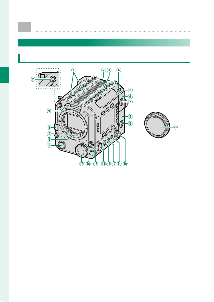
Camera Body
Top/Front/Inside
A
Accessory mounting screw holes
................................................................17, 54
B
Handle attachment mount ..................... 52
C
LCD cable release lever ..............................55
D
ON/OFF switch ............................................ 56
E
LCD cable connector cover
(detachable)........................................19, 54
F
Battery-chamber cover ............................. 32
G
Battery-chamber cover latch .................. 32
H
Memory card slot cover ............................ 39
I
Memory card slot cover latch .................. 39
J
Selector dial .................................................. 11
K
BACK button ................................................. 11
L
Lock switch ................................................... 15
M
GRAB button ................................................. 13
N
REC button .................................................... 13
O
Focus mode selector .................................. 13
P
Multi-function selector dial
...................................................................... 14
Q
Multi-function dial ..................................... 14
R
Lens signal contacts
S
Lens release button .................................... 46
T
Lens lock lever ........................................45, 47
U
DC OUT 12 V connector ..........................197
V
Body cap
3
1
Before You Begin
Parts of the Camera
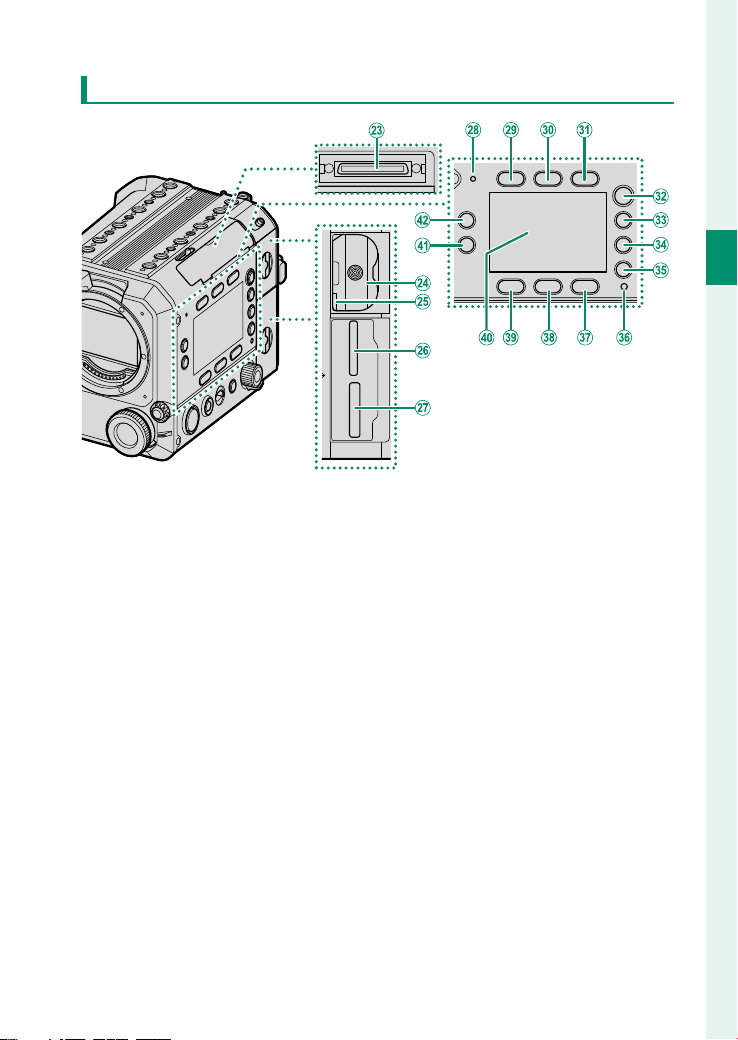
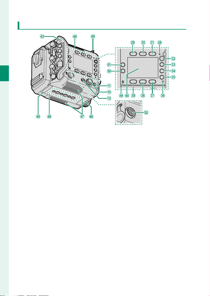
Top/Front/Inside (Continued)
W
LCD cable connector .................................. 54
X
Battery chamber ......................................... 32
Y
Battery latch ................................................. 35
Z
Memory card slot 2
(for SD memory cards) ........................... 39
a
Memory card slot 1
(for CFexpress Type B cards) .................. 39
b
Microphone .................................................. 62
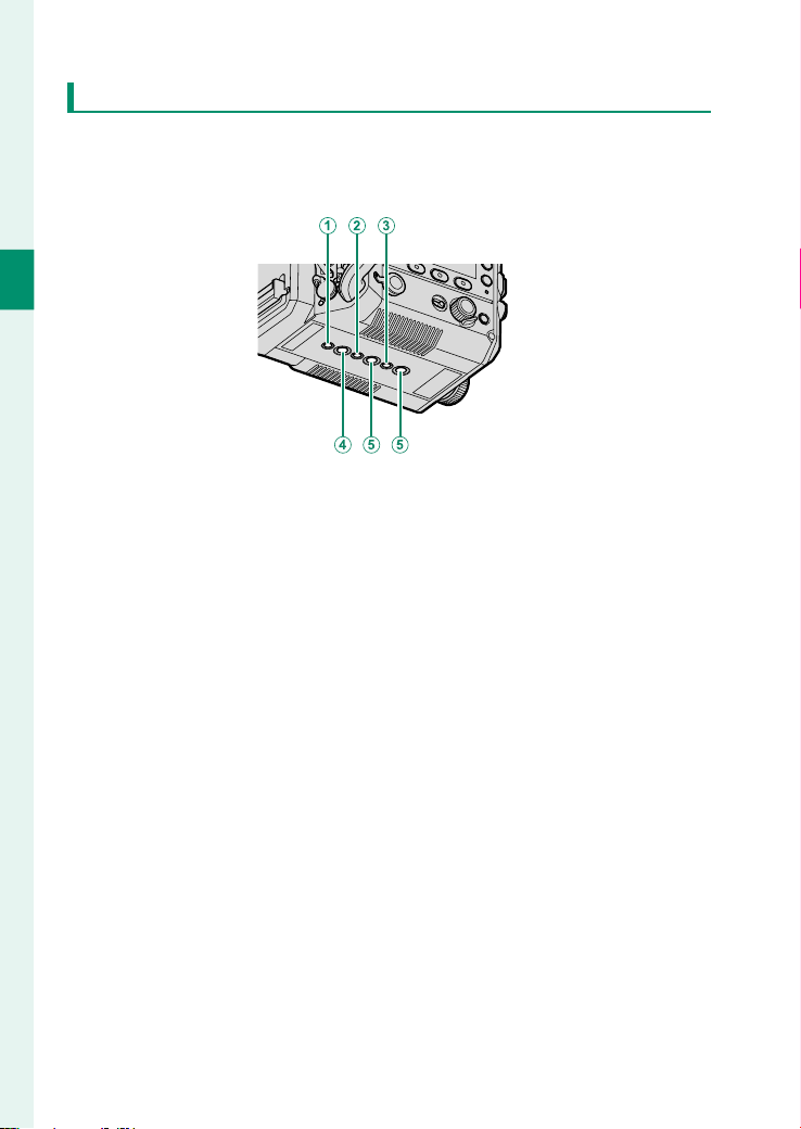
c
Screen button 1 .....................................10, 70
d
Screen button 2 .....................................10, 71
e
Screen button 3 .....................................10, 72
f
HOME button ...................................................9
g
USER button ....................................................9
h
PLAY button .....................................................9
i
MENU button ...................................................9
j
Indicator lamp ....................................16, 176
k
Screen button 6 .....................................10, 76
l
Screen button 5 .....................................10, 74
m
Screen button 4 .....................................10, 73
n
Side monitor ....................................................8
o
Fn2 button ..................................................181
p
Fn1 button ..................................................181
4
1
Before You Begin
Outside/Bottom
q
Cable protector (detachable)
r
Exhaust vent ................................................. 20
s
Measure hook .............................................. 20
t
Serial number plate.................................... 25
u
Air intakes ..................................................... 20
v
Tripod plate attachment holes ............... 17
w
Speaker ....................................................64, 96
x
Fn4 button ..................................................181
y
Fn3 button ..................................................181
z
LENS Connector (12-pin) ........................196
5
1
Before You Begin
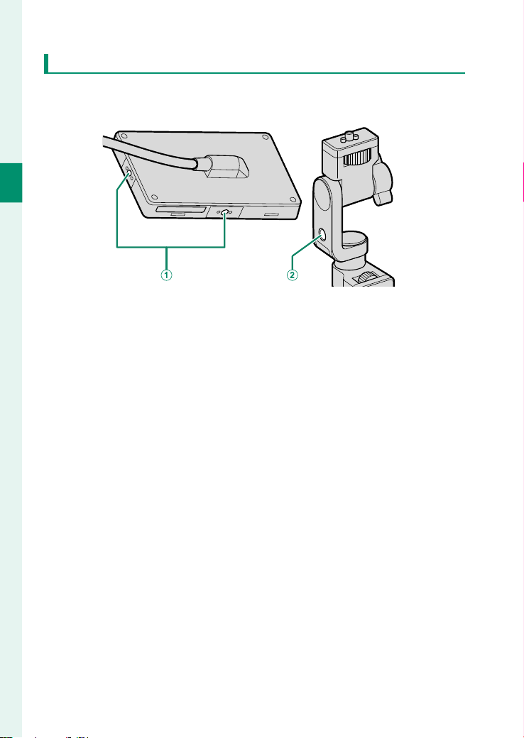
Parts of the Camera
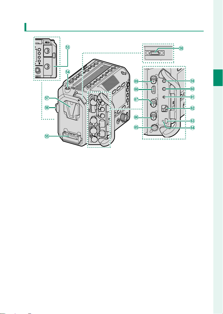
Back
0
Wi-Fi antenna (internal) ........................... 21
1
Release button ............................................. 53
2
V-mount battery attachment terminal
....................................................................198
3
V-mount battery release button ..........198
4
V-mount battery attachment mount
....................................................................198
5
Handle connection terminal ...................52
6
Microphone connector (⌀ 3.5mm) ....... 63
7
Headphone jack (⌀ 3.5mm)
8
Remote release connector (⌀ 2.5mm)
9
LAN connector ...........................................102
A
USB connector (Type-C)
B
Hole to screw USB cable
C
DC IN connector .......................................... 37
D
GENLOCK connector (BNC type)
...........................................................130, 197
E
TC IN/TC OUT connector (BNC type)
...........................................................147, 196
F
HDMI OUT connector (Type A) .............196
G
SDI OUT connector (BNC type) .............196
6
1
Before You Begin
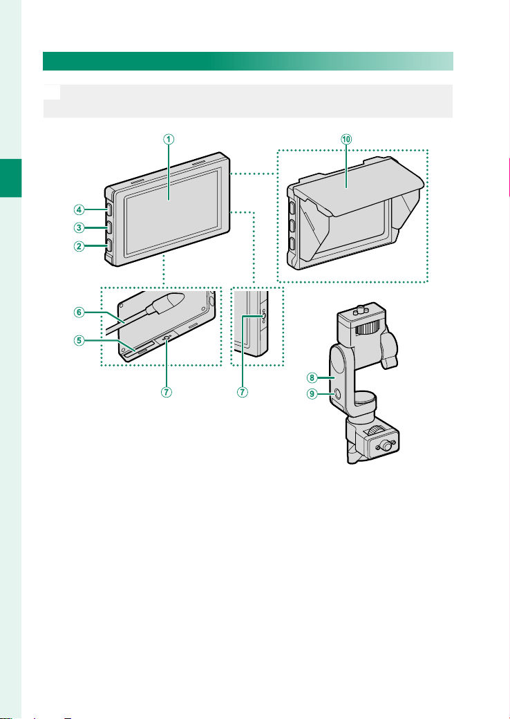
LCD Monitor
N
See page54 for instructions on how to attach the LCD monitor and
LCD attachment, and how to attach them to the camera body.
A
LCD monitor ...........................................26, 92
Touch screen ..........................................23, 86
B
DISP (display) button ................................. 23
C
Fn7 button ..................................................181
D
Fn6 button ..................................................181
E
Serial number plate.................................... 25
F
LCD cable ...................................................... 54
G
Accessory mounting screw holes
...................................................................... 24
H
LCD attachment
I
Accessory mounting screw hole ............. 24
J
LCD monitor hood
7
1
Before You Begin
Parts of the Camera
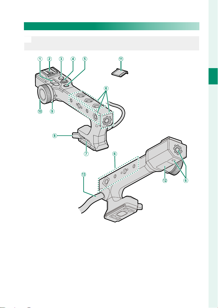
Handle
N
See page 52 for instructions on how to attach the handle to the
camera body.
A
Zoom lever ..............................................22, 84
B
Hot shoe
C
REC button .................................................... 13
D
Focus stick (focus lever).......................21, 80
E
Fn5 button ..................................................181
F
Accessory mounting screw holes
................................................................22, 54
G
Lock lever adjustment screw ................... 52
H
Lock lever ....................................................... 52
I
Multi-function selector dial ..................... 14
J
Multi-function dial ..................................... 14
K
Hot shoe cover
L
Serial number plate.................................... 25
M
Handle cable ................................................ 52
8
1
Before You Begin
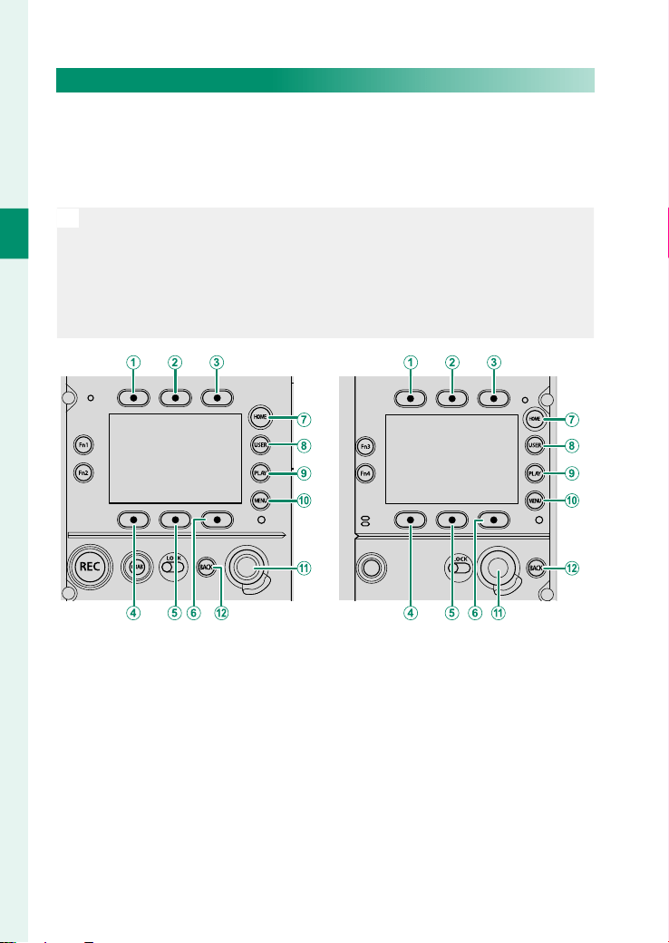
Side Monitors
You can use the side monitors to check the shooting settings and
select les to play back. Use the buttons and dials around the
monitors to switch displays, change settings, and operate the
menu.
N
•
The side monitors are located on both the inside and outside of the
camera body. The side monitors, buttons, and dials on the left and
right sides are identical. Operating a button or dial on either side will
change the display on both monitors.
•
Use LCD SETTING > SIDE MONITOR BRIGHTNESS in SET UP to ad-
just the brightness of the side monitors.
Inside Outside
A
Screen button 1
B
Screen button 2
C
Screen button 3
D
Screen button 4
E
Screen button 5
F
Screen button 6
G
HOME button
H
USER button
I
PLAY button
J
MENU button
K
Selector dial
L
BACK button
9
1
Before You Begin
Parts of the Camera
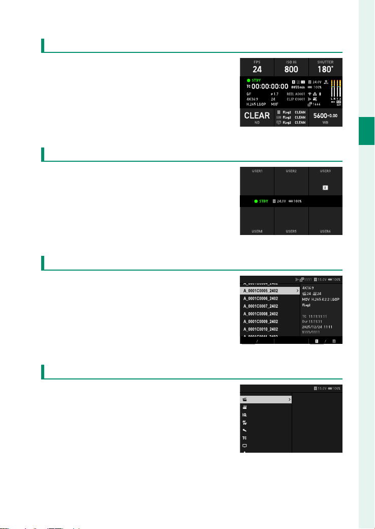
HOME Button
Press HOMEto display the main shooting
settings on the side monitors (P 70).
USER Button
Press USER to display the pre-assigned
functions on the side monitors (P 187).
GF 4K 16:9
±0.0 1.5dB
IMAGE FORMAT
RESOLUTION/ASPECT RATIO
FILM SIMULATION
PRESS DIAL:CUSTOM
A
UTO1
EXP. COMPENSATION
MANUAL ADJUSTMENT
INTERNAL MIC LEVEL
COOLING FAN SETTING
PLAY Button
Press PLAY to display the playback set-
tings on the side monitors. You can se-
lect les to be played back on the LCD
monitor and con gure the playback set-
tings (P 90).
CLIP LIST
STILLMOVIE
SETTING
MENU Button
Press the MENU button to display the
menu on the side monitors. You can con-
gure the shooting settings and camera
settings (P 118).
MENU
PROJECT
RECORDING
IQ
FOCUS
AUDIO
TIME CODE
MONITOR
USER
IMAGE FORMAT
RESOLUTION
PROJECT FPS
F-Log/HLG/RAW
FILM SIMULATION
LUT SETTING
MEDIA REC SETTING
CLIP SETTING
10
1
Before You Begin
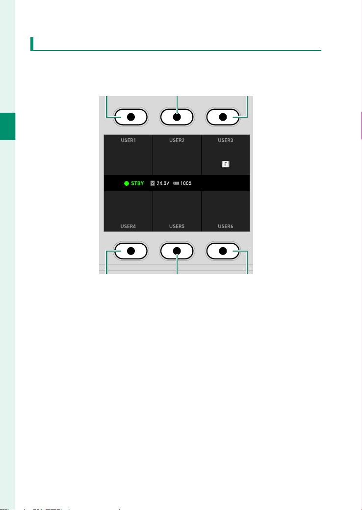
Screen Buttons
Press the screen buttons (1-6) to use the functions indicated
above or below the buttons or to change the assigned settings.
Screen button 1 Screen button 2 Screen button 3
GF 4K 16:9
±0.0 1.5dB
IMAGE FORMAT
RESOLUTION/ASPECT RATIO
FILM SIMULATION
A
UTO1
EXP. COMPENSATION
MANUAL ADJUSTMENT
INTERNAL MIC LEVEL
COOLING FAN SETTING
PRESS DIAL:CUSTOM
Screen button 4 Screen button 5 Screen button 6
11
1
Before You Begin
Parts of the Camera
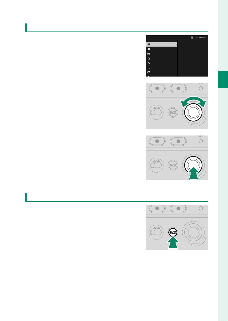
Selector Dial
Use the selector dial to operate the
menu and playback settings.
MENU
PROJECT
RECORDING
IQ
FOCUS
AUDIO
TIME CODE
MONITOR
USER
IMAGE FORMAT
RESOLUTION
PROJECT FPS
F-Log/HLG/RAW
FILM SIMULATION
LUT SETTING
MEDIA REC SETTING
CLIP SETTING
•
Rotate the dial left or right to move the
cursor.
•
Press the center to select an item.
BACK Button
Press BACK on the playback settings or
menu display to return to the previous
display without changing the settings.
12
1
Before You Begin
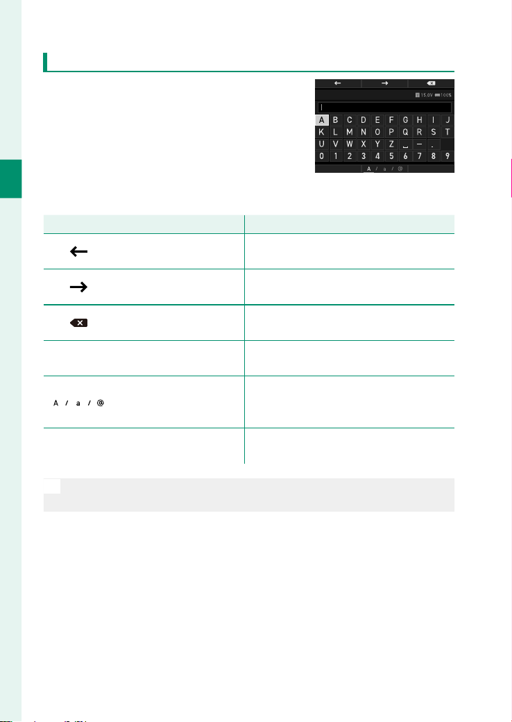
Touch Screen Mode on the Side Monitors
When entering text such as a password,
an on-screen keyboard will be displayed
on the side monitors. Tap the screen or
press the screen buttons to enter char-
acters.
PASSWORD
CANCEL DONE
The functions of the screen buttons are as follows.
Button
Button
Description
Description
Move left
Move left
(Screen button 1)
(Screen button 1)
Move the cursor one character to the left.
Move right
Move right
(Screen button 2)
(Screen button 2)
Move the cursor one character to the
right.
Delete
Delete
(Screen button 3)
(Screen button 3)
Delete one character before the cursor.
CANCEL
CANCEL
Cancel
Cancel
(Screen button 4)
(Screen button 4)
Exit text entry without saving changes.
Switch character type
Switch character type
(Screen button 5)
(Screen button 5)
Switch between uppercase letters, low-
ercase letters, and symbols each time the
button is pressed.
DONE
DONE
Done
Done
(Screen button 6)
(Screen button 6)
Save changes and exit text entry.
N
The layout and types of keys on the display vary depending on the
item being entered.
13
1
Before You Begin
Parts of the Camera
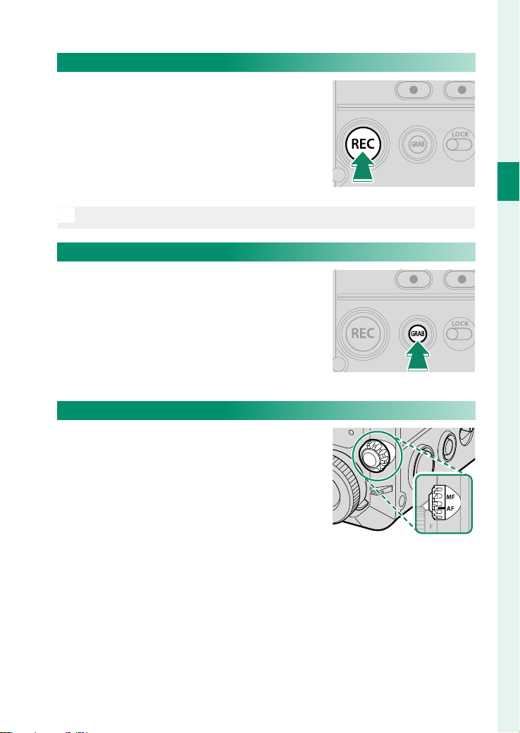
REC Button
Press REC to start movie recording and
the button will light in red. Press the but-
ton again to stop recording and it will
turn o .
N
During playback, pressing the button will not start recording.
GRAB Button
Press GRAB to capture a still image from a
movie (P 66).
Focus Mode Selector
Use the focus mode selector to switch
the focus modes (P 80).
14
1
Before You Begin
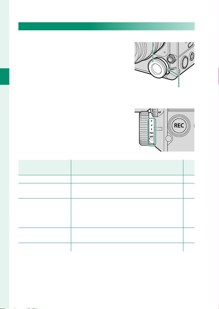
Multi-Function Dial
Rotate the multi-function dial to adjust
settings for the function selected with
the multi-function selector dial.
Multi-function dial
Multi-function selector
dial
The functions that can be adjusted with
the multi-function dial are as follows:
Multi-function selector
Multi-function selector
dial
dial
Description
Description
P
P
F(focus)
F(focus) You can adjust the focus when using manual focus. 82
Z(zoom)
Z(zoom)
You can adjust zoom when using a lens that sup-
ports power zoom.
84
I(iris)
I(iris)
While RECORDING > IRIS is set to an option other
than AUTO , when a lens with no aperture rings is
used or when the lens aperture ring is in the C posi-
tion, you can adjust the iris.
83
ND (ND lter)
ND (ND lter)
You can adjust the ND fi lter density when ON is se-
lected for the ND fi lter.
73
OFF
OFF Multi-function dial operation will be disabled. —

15
1
Before You Begin
Parts of the Camera
Lock Switch
Use the lock switch to lock buttons and
dials.
•
Use the inside lock switch to lock the buttons and dials on the
inside, the focus mode selector, and the multi-function dial.
•
Use the outside lock switch to lock the buttons and dials on the
outside, and the REC and GRAB buttons on the front.

16
1
Before You Begin
The Indicator Lamp
Camera status is shown by the indicator
lamp.
Indicator lamp
Indicator lamp
Camera status
Camera status
Blinks green and orange
Uploading selected fi les via the network when the cam-
era is off .
Glows orange
Recording fi les. No additional fi les can be taken at this
time.
Blinks red Lens or memory error.
N
•
Warnings may also appear in the display.
•
The indicator lamp shows the status of its connection to computers,
Frame.io, and the like (P 98).
•
While the function button to which AF-ON is assigned is pressed, the
indicator lamp glows or blinks green.
17
1
Before You Begin
Parts of the Camera
Accessory Mounting Screw Holes/
Tripod Plate Attachment Holes
Accessory Mounting Screw Holes (on the Camera Body)
The supplied LCD attachment and other optional accessories can
be attached to the accessory mounting screw holes on the top of
the camera (P 54). The dimensions are as follows:
A
Accessory mounting screw holes
Screw type: 3/8-16UNC (x 8)
Screw hole depth: 6 mm
B
Accessory mounting screw holes
Screw type: 1/4-20UNC (x 6)
Screw hole depth: 6 mm
C
Accessory mounting screw holes
Screw type: 3/8-16UNC (x 4)
Screw hole depth: 10.5 mm
18
1
Before You Begin
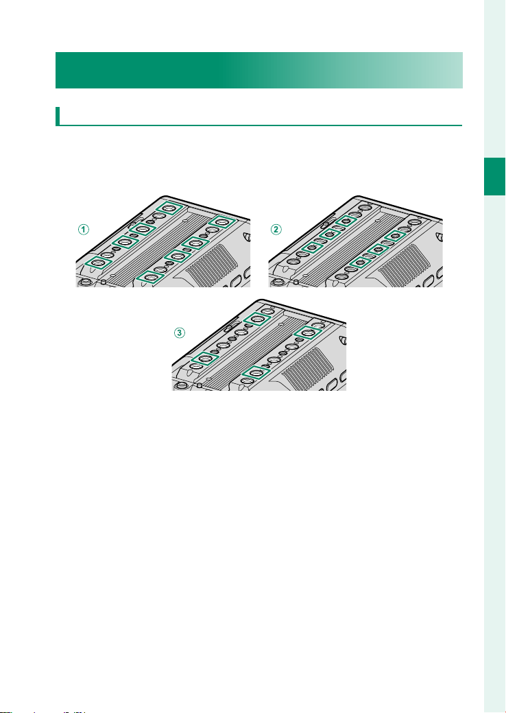
Tripod Plate Attachment Holes
Optional tripod plates or bridge plates can be attached to the
tripod plate attachment holes on the bottom of the camera. The
dimensions are as follows:
A
Tripod plate attachment hole
Screw type: 1/4-20UNC (x 1)
Screw hole depth: 8 mm
B
Tripod plate attachment hole
Screw type: 1/4-20UNC (x 1)
Screw hole depth: 12 mm
C
Tripod plate attachment hole
Screw type: 1/4-20UNC (x 1)
Screw hole depth: 11 mm
D
Tripod plate attachment hole
Screw type: 3/8-16UNC (x 1)
Screw hole depth: 12 mm
E
Tripod plate attachment hole
Screw type: 3/8-16UNC (x 2)
Screw hole depth: 11 mm
19
1
Before You Begin
Parts of the Camera
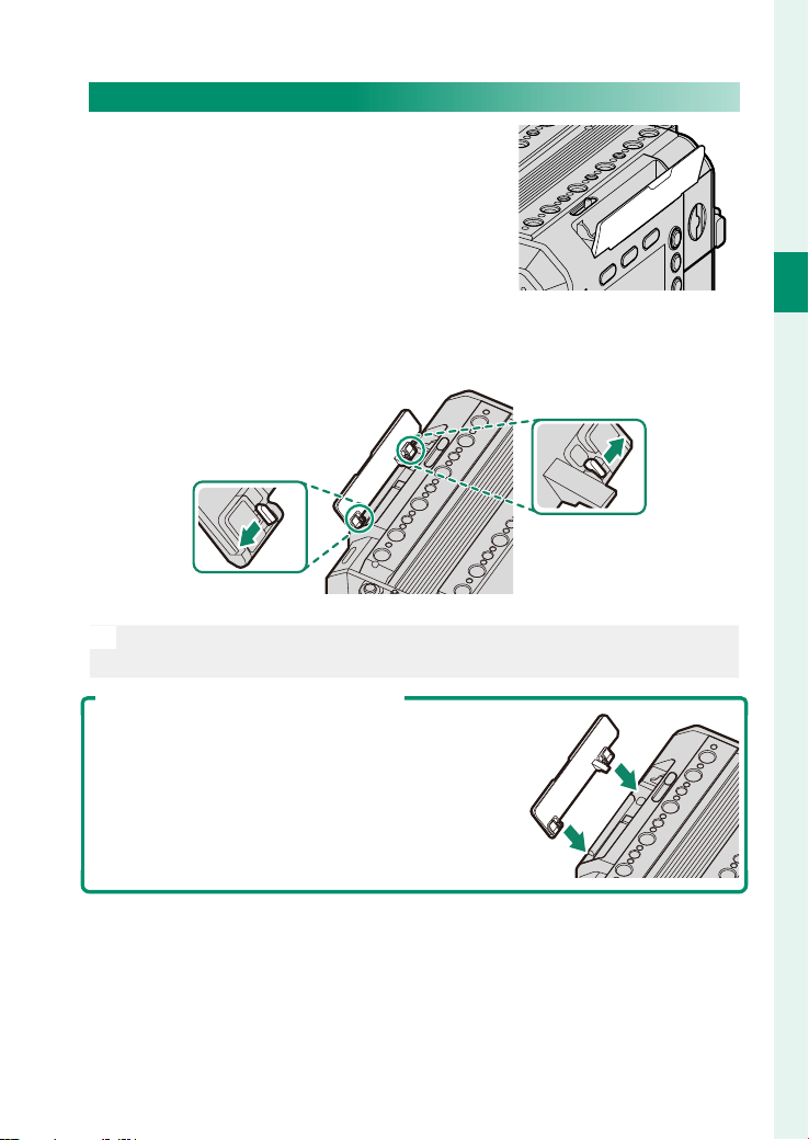
LCD Cable Connector Cover (Detachable)
The LCD cable connector cover can be
removed if the cover interferes with the
rig or accessories when attaching them.
To remove the LCD cable connector cover, pull the orange levers
inside the cover as shown.
N
Attach the LCD cable terminal cover when you do not use the LCD
monitor.
Attaching the LCD Cable Connector Cover
Press in the LCD cable connector cover as shown
to attach it.

20
1
Before You Begin
Measure Hook
The hook indicates the position of the
image sensor. Attach the tip of a mea-
sure to the measure hook to measure
the exact distance between the image
sensor and the subject.
Air Intakes/Exhaust Vent
Do not cover the air intakes or exhaust
vent with tape or other materials or
place any obstructions near them. Fail-
ure to observe this precaution may re-
duce cooling performance or damage
the camera.
Air intakes
Exhaust vent
21
1
Before You Begin
Parts of the Camera
Wi-Fi Antenna (Internal)
The camera has a Wi-Fi antenna inside,
so covering it with your hand or metal
objects may interrupt Wi-Fi communica-
tion.
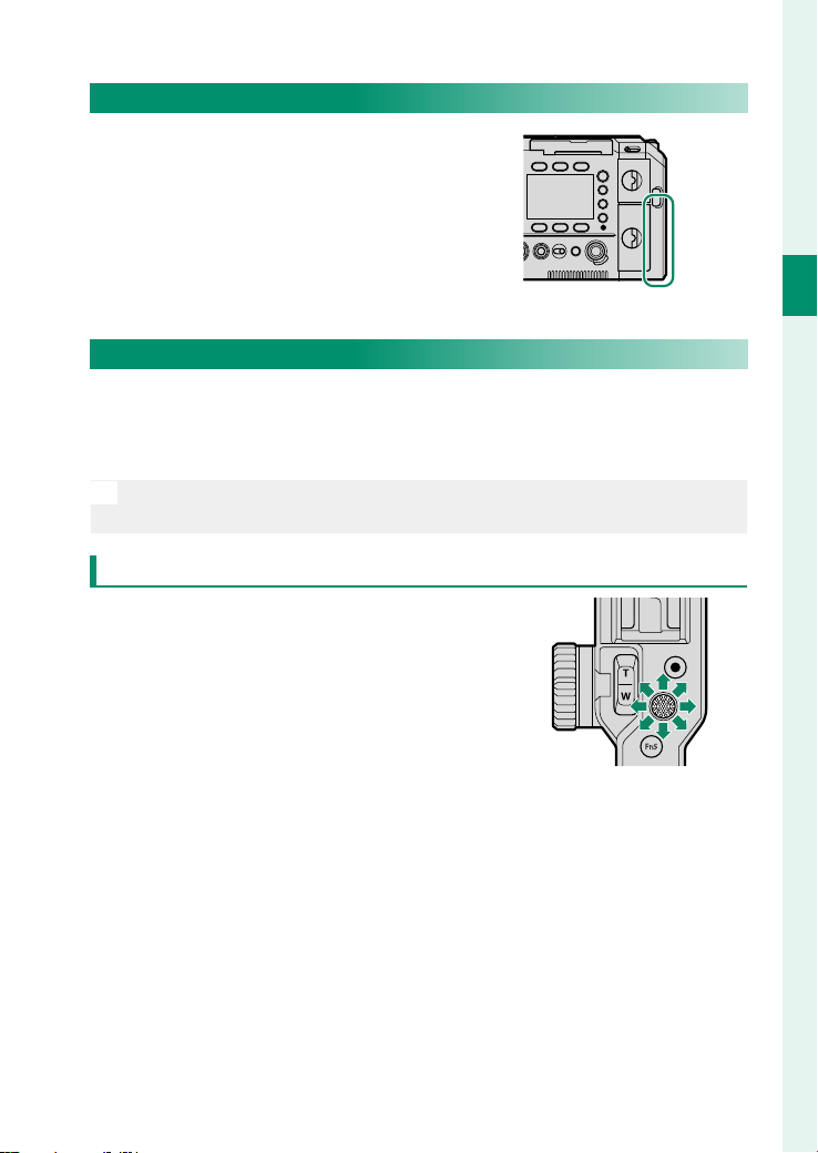
Handle
Attach the handle to the camera body to set the focus area with
the focus stick (focus lever) or operate the zoom with the zoom
lever.
N
Attach the handle to the handle attachment mount on the top of the
camera body (P 52).
Focus Stick (Focus Lever)
Tilt or press the focus stick to select the
focus area. The focus stick can also be
used to navigate the menus.
22
1
Before You Begin
Zoom Lever
You can adjust zoom with the zoom
lever when using a lens that supports
power zoom. The zoom speed changes
depending on how far you press the
zoom lever (P 84).
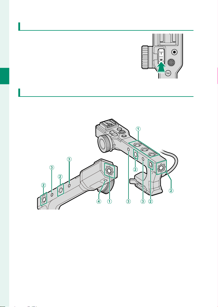
Accessory Mounting Screw Holes (on the Handle)
The supplied LCD attachment and other optional accessories can
be attached. The dimensions are as follows:
A
Accessory mounting screw holes
Screw type: 3/8-16UNC (x 4)
Screw hole depth: 12.5 mm
B
Accessory mounting screw holes
Screw type: 3/8-16UNC (x 5)
Screw hole depth: 12 mm
C
Accessory mounting screw holes
Screw type: 1/4-20UNC (x 4)
Screw hole depth: 8 mm
D
Accessory mounting screw holes
Screw type: 1/4-20UNC (x 1)
Screw hole depth: 7 mm

23
1
Before You Begin
Parts of the Camera
LCD Monitor
Connect the LCD monitor to the camera to check the shooting
display and play back recorded movies. The LCD monitor can
also be used as a touch screen during recording and playback
(P 86).
N
Attach the LCD monitor to the accessory mounting screw holes on the
top of the camera body or handle (P 54).
DISP Button
Press DISP to enable or disable the in-
formation display on the LCD monitor.
Press and hold the button to ip the LCD
monitor display vertically or horizontally.
24
1
Before You Begin
Accessory Mounting Screw Holes (on the LCD Monitor)
Optional accessories can be attached. The dimensions are as fol-
lows:
A
Accessory mounting screw holes
Screw type: 1/4-20UNC (x 2)
Screw hole depth: 7.5 mm
B
Accessory mounting screw holes
Screw type: 1/4-20UNC (x 1)
25
1
Before You Begin
Parts of the Camera
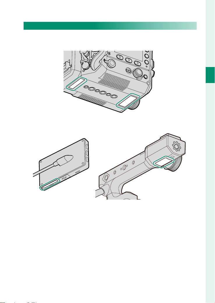
The Serial Number Plates
Do not remove the serial number plates, which provide the
CMIITID, serial number, and other important information.
Camera body
LCD monitor Handle
26
1
Before You Begin
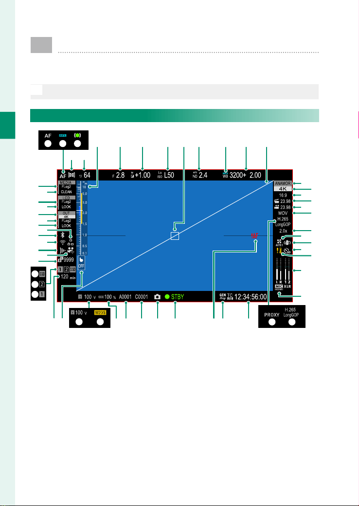
Camera Displays
The following information is displayed on the LCD monitor
and side monitors during shooting.
O
For illustrative purposes, displays are shown with all indicators lit.
LCD Monitor Display
D E
G H I K M N
P
R
T
X
Q
O
S
U
W
Z
deghijk
V
Y
a
J
f
F
s
y
2
4
w
u
v
t
x
z
1
3
B CA
c b
lmno
L
r
q
p
0

27
1
Before You Begin
Camera Displays
A
Focus mode .................................................. 13
B
AF lock ..........................................................186
C
Focus indicator
D
Metering ........................................................ 85
E
Shutter speed ............................................... 72
F
Distance indicator
G
Aperture ......................................................... 83
H
Exposure compensation .........................127
I
Sensitivity ...................................................... 71
J
Focus area ..................................................... 81
K
ND (Neutral Density) fi lter indicator ..... 73
L
AWB lock
M
White balance ............................................. 76
N
Virtual horizon ...........................................157
O
Image format .............................................118
P
Resolution ................................................... 119
Q
Aspect ratio.................................................119
R
Project frame rate .....................................119
S
Recording frame rate ................................. 70
T
File format ...................................................124
U
Crop factor
V
Cooling fan settings .................................174
W
IS mode ........................................................128
X
Self-timer indicator ..................................128
Y
Temperature warning ......................40, 230
Z
Recording level ..........................................142
a
XLR recording level ...................................142
b
Codec............................................................125
c
Proxy (only when rec ProRes) ................125
d
Time code ....................................................146
e
Genlock ........................................................ 130
f
Focus warning ...........................................228
g
Camera status ● STBY/REC ..................... 62
h
Grab ................................................................66
i
Clip No.
j
Reel No. ........................................................126
k
NP-W235 battery level .............................. 57
l
W235 battery mode ................................... 34
m
External power source ............................... 37
n
Touch AF button
o
Media recording time
p
Recording media CF .................................124
q
Recording media SD ................................124
r
Recording media SSD ..............................124
s
Frame.io upload progress .......................103
t
Remote recording function connection
status
u
Frame.io connection status ...................104
v
Wireless connection
w
Bluetooth ON/OFF
x
Ethernet connection
y
LOOK SDI/HDMI LOOK/CLEAN status
...................................................................... 75
z
LOOK SDI/HDMI FS/F-Log/HLG/RAW
....................................................................120
0
LOOK SDI/HDMI output setting ............149
1
LOOK LCD LOOK/CLEAN status ............... 75
2
LOOK LCD FS/F-Log/HLG ........................120
3
LOOK media LOOK/CLEAN status .......... 75
4
LOOK media FS/F-Log/HLG ...................120
28
1
Before You Begin
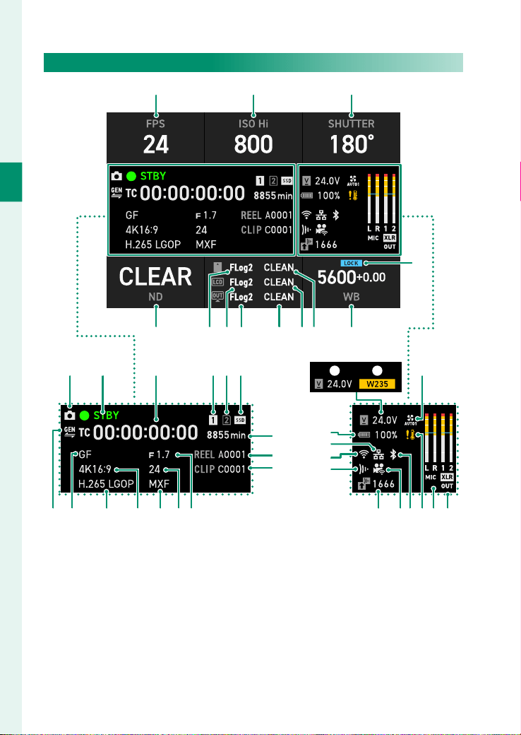
Side Monitor Display
A B C
E
D
I HL
PQU T
V
W
Y
f
g
h
OedcaZ b
SRkm jlo n i
K FJ G
X
M N

29
1
Before You Begin
Camera Displays
A
Recording frame rate ................................. 70
B
Sensitivity ...................................................... 71
C
Shutter speed ............................................... 72
D
AWB lock
E
White balance ............................................. 76
F
LOOK media LOOK/CLEAN status .......... 75
G
LOOK LCD LOOK/CLEAN status ............... 75
H
LOOK SDI/HDMI LOOK/CLEAN status
...................................................................... 75
I
LOOK SDI/HDMI FS/F-Log/HLG/RAW
....................................................................120
J
LOOK LCD FS/F-Log/HLG ........................120
K
LOOK media FS/F-Log/HLG ...................120
L
ND (Neutral Density) fi lter indicator ..... 73
M
External power source ............................... 37
N
W235 battery mode ................................... 34
O
Cooling fan settings .................................174
P
XLR recording level ...................................142
Q
Recording level ..........................................142
R
Temperature warning ......................40, 230
S
Bluetooth ON/OFF
T
Remote recording function connection
status
U
Frame.io upload progress .......................103
V
Frame.io connection status ...................104
W
Wireless connection
X
Ethernet connection
Y
NP-W235 battery level .............................. 57
Z
Grab ................................................................66
a
Camera status ● STBY/REC ..................... 62
b
Time code ....................................................146
c
Recording media CF .................................124
d
Recording media SD ................................124
e
Recording media SSD ..............................124
f
Media recording time
g
Reel No. ........................................................126
h
Clip No.
i
Aperture ......................................................... 83
j
Project frame rate .....................................119
k
File format ...................................................124
l
Resolution ................................................... 119
m
Media rec setting ......................................125
n
Image format .............................................118
o
Genlock ........................................................ 130

30
MEMO

31
First Steps

32
2
First Steps
Charging the Supplied Battery
Charge the supplied battery.
Charging the Supplied Battery
Using the supplied battery allows you to record using the cam-
era's basic functions. You can also replace the V-mount battery
without turning o the camera.
O
•
For safety reasons, the supplied battery is not charged at the time of
purchase. The camera will not function if the supplied battery is not
charged; be sure to charge the supplied battery before use.
•
Charging takes about 180minutes.
•
Turning on the camera while it is charging may result in a longer
charging time than charging when the power is o .
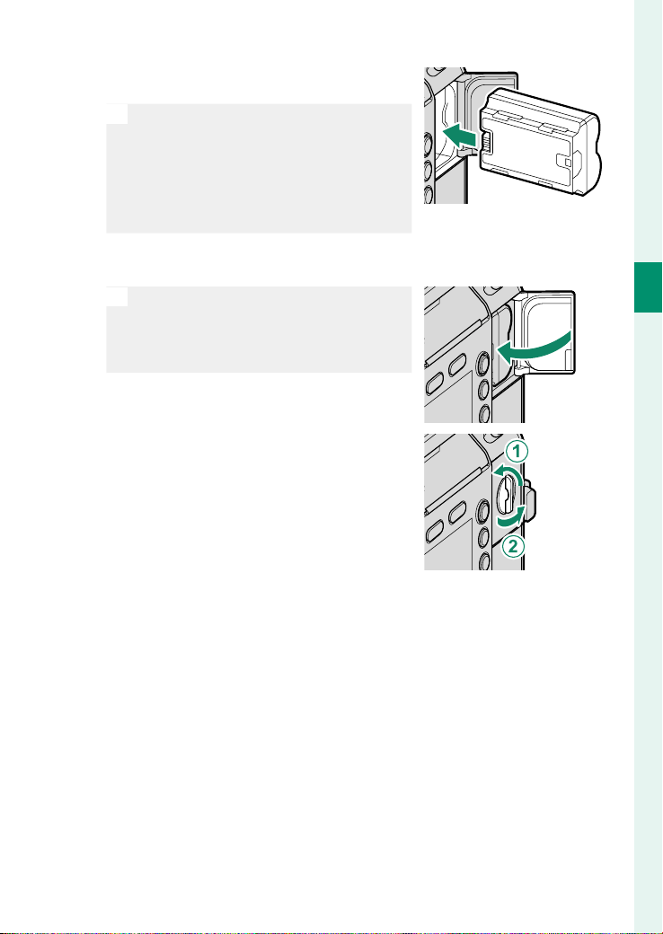
1
Open the battery-chamber cover.
Lift the battery-chamber latch (
A
),
rotate the latch as shown (
B
), and
open the battery-chamber cover (
C
).
O
•
Do not open the battery-chamber
cover when the camera is on. Fail-
ure to observe this precaution could
damage les or memory cards.
•
Do not use excessive force when
handling the battery-chamber cover.
33
2
First Steps
Charging the Supplied Battery
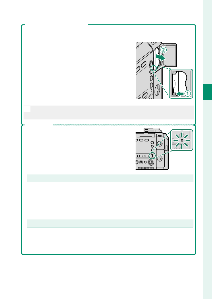
2
Insert the supplied battery as shown.
O
•
Inserting the supplied battery in the
wrong orientation may damage the
camera. Insert it in the correct orien-
tation.
•
Con rm that the supplied battery is
securely latched.
3
Close the battery-chamber cover.
O
If the cover does not close, check that
the supplied battery is in the correct
orientation. Do not attempt to force
the cover shut.
4
Rotate the battery-chamber latch as
shown (
A
), and tilt the latch down
(
B
).
5
Connect the supplied AC power adapter to charge the sup-
plied battery (P 37).

34
2
First Steps
W235 Battery Mode
The camera will operate in W235 battery mode when it is turned on while
it is powered only by the supplied battery.
The following restrictions apply in W235 battery mode:
•
The 12-pin connector for lens connection, SDI OUT connector, HDMI OUT
connector, and DC OUT 12 V connector cannot be used.
•
An external SSD cannot be used.
•
Wireless LAN connection, wired LAN connection, and Bluetooth connec-
tion are not available.
•
8K image quality cannot be selected for RESOLUTION .
O
Attaching the AC power adapter or V-mount battery will exit W235 bat-
tery mode.
35
2
First Steps
Charging the Supplied Battery
Removing the Supplied Battery
Before removing the supplied battery, turn the camera o and open the
battery-chamber cover.
To remove the supplied battery, press the battery
latch to the side with your fi nger to release the lock
(
A
), and remove the supplied battery (
B
).
O
The supplied battery may become hot after using the camera. Observe
caution when removing the supplied battery.
Charge Status
•
When the camera is turned off , the indicator lamp
shows the charge status of the supplied battery.
Indicator lamp
Indicator lamp
Battery status
Battery status
Glows green Battery charging
Off Charging complete
Blinks green Battery fault
•
When the camera is turned on, the icon on the screen shows the charge status
of the supplied battery.
Icon
Icon
Battery status
Battery status
y
Battery charging
e
Charging complete
z
Battery fault

36
2
First Steps
Charging the Supplied Battery
O
•
Do not a x labels or other objects to the supplied battery. Failure to
observe this precaution could make it impossible to remove the bat-
tery from the camera.
•
Do not short the supplied battery terminals. This may cause over-
heating and pose a safety hazard.
•
Read the cautions for the supplied battery in "For Your Safety".
•
Use only genuine Fujifilm rechargeable batteries designated for use
in this camera. Failure to observe this precaution could result in
product malfunction.
•
Do not remove the labels from the battery or attempt to split or peel
the outer casing.
•
The supplied battery gradually loses its charge when not in use.
Charge the supplied battery one or two days before use.
•
If the supplied battery fails to hold a charge, it has reached the end of
its charging life and must be replaced. Purchase a new battery.
•
Unplug the AC power adapter from the power outlet when it is not in
use.
•
If the supplied battery is left for long periods without charging, you
may nd that its quality degrades or that it no longer holds a charge.
Charge the supplied battery regularly.
•
Remove dirt from the supplied battery terminals with a clean, dry
cloth. Failure to observe this precaution could prevent the supplied
battery from charging.
•
Note that charging times increase at low or high temperatures.
37
2
First Steps
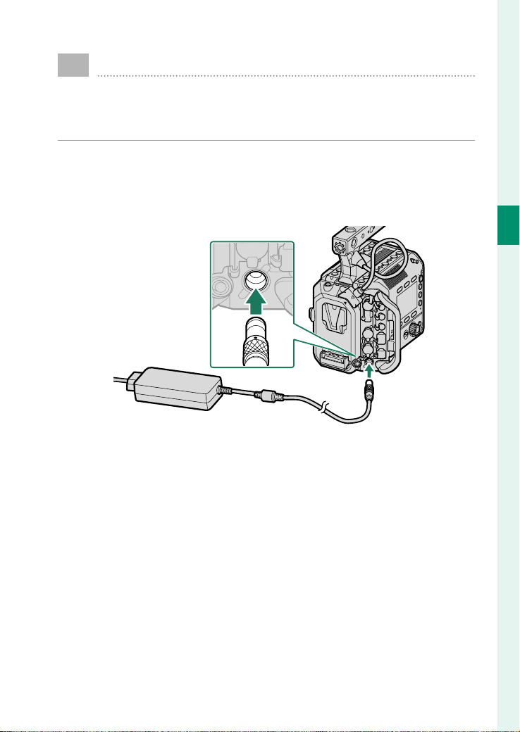
Using the AC Power Adapter
Using the supplied AC power adapter, you can use the
camera without the supplied battery, or charge the sup-
plied battery in the camera.
Connect the AC power adapter cable to the DC IN connector of
the camera with the red mark on the plug facing up as shown
in the gure and then plug the AC cable into an indoor power
outlet.

38
2
First Steps
Using the AC Power Adapter
O
•
The supplied AC power adapter is compatible with power supplies of
100 to 240 V and can be used overseas (a plug adapter or AC cable may
be needed for overseas use).
•
Do not use the AC power adapter with other devices. Failure to ob-
serve this precaution could cause malfunction.
•
If the supplied battery is in the camera when removing the AC power
adapter, the screen display and terminal output will be turned o ,
and no operation other than turning o the camera can be per-
formed (P 199).
•
If the supplied battery is low or the camera is used in a low-temper-
ature environment, removing the AC power adapter could cause the
camera to stop functioning, even if the supplied battery is in the cam-
era.
•
Use only the supplied AC power adapter with the DC IN connector.
We cannot guarantee the product if you use an adapter other than
the one supplied.
N
•
Instead of the AC power adapter, you can also use a V-mount battery
to charge the supplied battery (P 198).
•
When both the AC power adapter and V-mount battery are used, the
power from the AC power adapter is prioritized for consumption.
39
2
First Steps
Inserting Memory Cards
Clips are stored on memory cards (sold separately).
N
The camera is equipped with two memory card slots. Use Slot 1 with
CFexpress cards and Slot 2 with SD, SDHC, or SDXC cards.
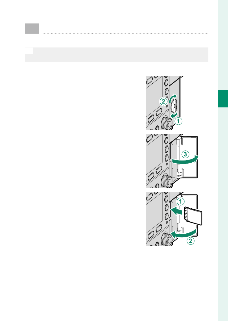
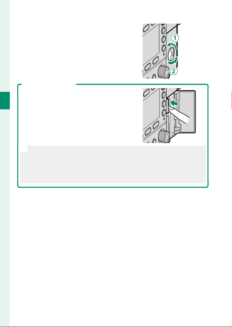
1
Open the memory card slot cover.
Lift the memory card slot cover latch
(
A
), rotate the latch as shown (
B
),
and open the cover (
C
).
2
Insert the memory card (
A
), and
close the memory card slot cover
(
B
).
40
2
First Steps
3
Rotate the memory card slot cover
latch as shown in the gure to lock
it (
A
), and then push the latch down
(
B
).
Removing Memory Cards
Turn the camera off and open the memory card
slot cover. Eject the card by pressing it in with a
finger and then slowly releasing it; the card can
then be removed by hand.
O
•
Press the center of the card.
•
Suddenly removing your finger from the card could cause the card to
fall from the slot. Remove your finger slowly.
•
If the camera displays a p icon, the memory card may be hot to the
touch. Wait for the card to cool before removing it.

41
2
First Steps
Inserting Memory Cards
Using Two Cards
The camera can be used with two cards, one in each of its two
slots. The method of recording to a memory card can be changed
using MEDIA REC SETTING > REC MEDIA in PROJECT .
Option
Option
Description
Description
Display
Display
SEQENTIAL
The card in the second slot is used only when the
card in the fi rst slot is full.
BACKUP Each fi le is recorded twice, once to each card.

42
2
First Steps
Compatible Memory Cards
•
The camera can be used with SD, SDHC, SDXC, and CFexpress
Type B memory cards. Both the UHS-I and UHS-II bus interfaces
are supported.
•
The type of memory card supported varies with the option se-
lect for PROJECT > MEDIA REC SETTING .
-
Record ProRes movies to CFexpress cards.
-
Movies with a bit rate of 720 Mbps can be recorded to CFexpress cards
or to cards with a Video Speed Class of V90 or better.
-
Movies with a bit rate of 360 Mbps can be recorded to CFexpress cards
or to cards with a Video Speed Class of V60 or better.
-
Movies with a bit rate of 100 Mbps or 200 Mbps can be recorded to
CFexpress cards or to cards with a Video Speed Class of V30 or better.
•
A list of supported memory cards is available on the Fuji lm
website. For details, visit:
https://fujifilm-x.com/support/compatibility/cameras/
.

43
2
First Steps
Inserting Memory Cards
O
•
Do not turn the camera off or remove the memory card while the memory
card is being formatted or data are being recorded to the card. Failure to
observe this precaution could damage the card.
•
When recording data on a memory card,
unlock the write-protect switch. Sliding
the write-protect switch to the LOCK side
will prevent you from recording clips or
formatting the card.
•
Memory cards are small and can be swallowed; keep out of reach of
children. If a child swallows a memory card, seek medical assistance
immediately.
•
miniSD or microSD adapters that are larger or smaller than memory
cards may not eject normally; if the card does not eject, contact your
Fujifilm dealer. Do not forcibly remove the card.
•
Do not affix labels or other objects to memory cards. Peeling labels
can cause camera malfunction.
•
Movie recording may be interrupted with some types of memory card.
•
Formatting a memory card in the camera creates a folder in which les
are stored. Do not rename or delete this folder. Also, do not edit, delete,
or rename les using a computer or other device. Renaming the les
on the camera can cause problems during playback.

44
2
First Steps
Inserting Memory Cards
Using an External SSD in Place of a Memory Card
This camera can save still images and movies to an SSD. Con-
nect the SSD to the USB connector, and then use MEDIA REC
SETTING > REC MEDIA in PROJECT to select the SSD. Turn the
camera o before disconnecting the SSD.
N
During playback, press m/n/o (Screen button 6) to select the SSD or
memory card to play back.

45
2
First Steps
Attaching a Lens
The camera can be used with the FUJIFILM G-mount lenses
manufactured by Fuji lm and PL-mount lenses.
O
Observe the following precautions when attaching or removing
(exchanging) lenses.
•
Check that the lenses are free of dust and other foreign matter.
•
Do not change lenses in direct sunlight or under another bright light
source. Light focused into the interior of the camera could cause it
to malfunction.
•
Attach the lens caps before exchanging lenses.
•
Do not rotate the lens while holding moving parts of the camera,
such as the aperture ring.
•
See the manual provided with the lens for information on use.
•
Be careful not to touch the camera’s internal parts.
G-mount Lenses
1
Tilt the lens lock lever as shown in the
gure.
2
Remove the body cap from the
camera and the rear cap from the
lens. Place the lens on mount,
keeping the marks on the lens and
camera aligned (
A
), and then slowly
rotate the lens in the direction of the
arrow until it clicks into place (
B
).
O
•
Rotate the lens until it clicks securely into place.
•
Do not press the lens release button while attaching the lens.

46
2
First Steps
3
Move the lens lock lever as shown in
the gure to lock the lens.
O
Do not press the lens lock lever too hard as it will not move all the
way to the end.
Removing Lenses
Turn the camera o , then tilt the lens lock lever
as shown in the gure (
A
), and while pressing
the lens release button (
B
), slowly rotate the
lens in the direction of the arrow (
C
).
O
To prevent dust accumulating on the lens or inside the camera, replace
the lens caps and camera body cap when the lens is not attached.
Lenses and Other Optional Accessories
The camera can be used with lenses and accessories for the FUJIFILM
G-mount.
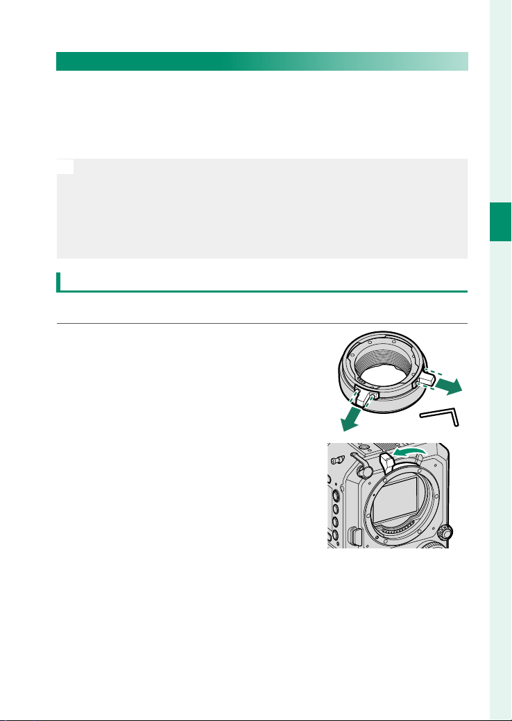
47
2
First Steps
Attaching a Lens
PL-mount Lenses
When using a PL-mount lens, attach the supplied PL-mount
adapter to the camera. For compatibility information on our sep-
arately sold PL-mount lenses, visit the following web site.
https://fujifilm-x.com/support/compatibility/cameras/
O
When using PL-mount lenses other than those mentioned above, note
the following:
•
We do not guarantee the operation of all PL-mount lenses.
•
To prevent damage to the camera or lens, use lenses that do not ex-
ceed the speci ed dimensions (P 195).
•
To adjust the ange focal length, use the supplied shim (P 192).
Attaching the PL-mount Adapter
Attach the PL-mount adapter to the camera.
1
Remove the PL lock levers from the
bayonet ring.
Use the supplied hex wrench (2mm).
2
Tilt the lens lock lever as shown in the
gure to release the lock.

48
2
First Steps
3
Align the red indicators on the cam-
era and the PL-mount adapter (
A
),
and then slowly rotate the PL-mount
adapter in the direction of the arrow
to attach it (
B
).
4
Move the lens lock lever as shown in
the gure to lock the adapter.
O
Do not press the lens lock lever too hard as it will not move all the
way to the end.
5
Align the red indicators on the
PL-mount adapter cover and the
PL-mount adapter, and then attach
the PL-mount adapter cover.
N
The PL-mount adapter cover cannot be used with other GFX series
cameras.
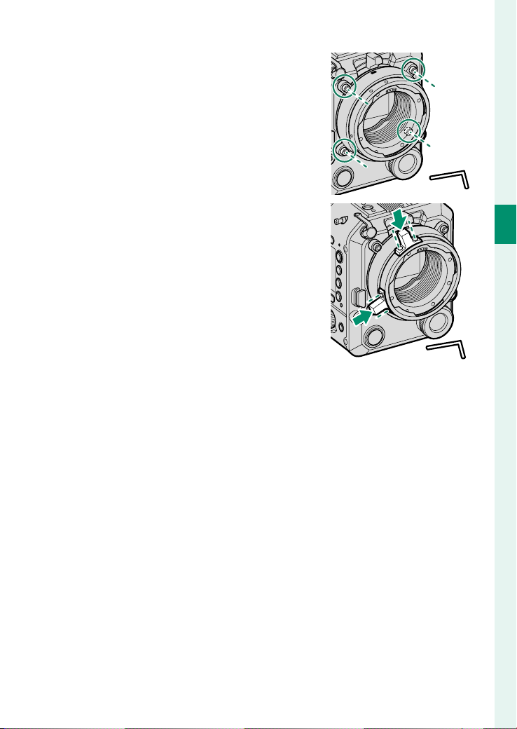
49
2
First Steps
Attaching a Lens
6
Tighten the bolts on the PL-mount
adapter cover to secure it to the cam-
era.
Use the supplied hex wrench (3mm)
to tighten the bolts. When using a
torque wrench, set the torque to
0.36N·m.
7
Attach the PL lock levers to the bayo-
net ring.
Use the supplied hex wrench (2mm).
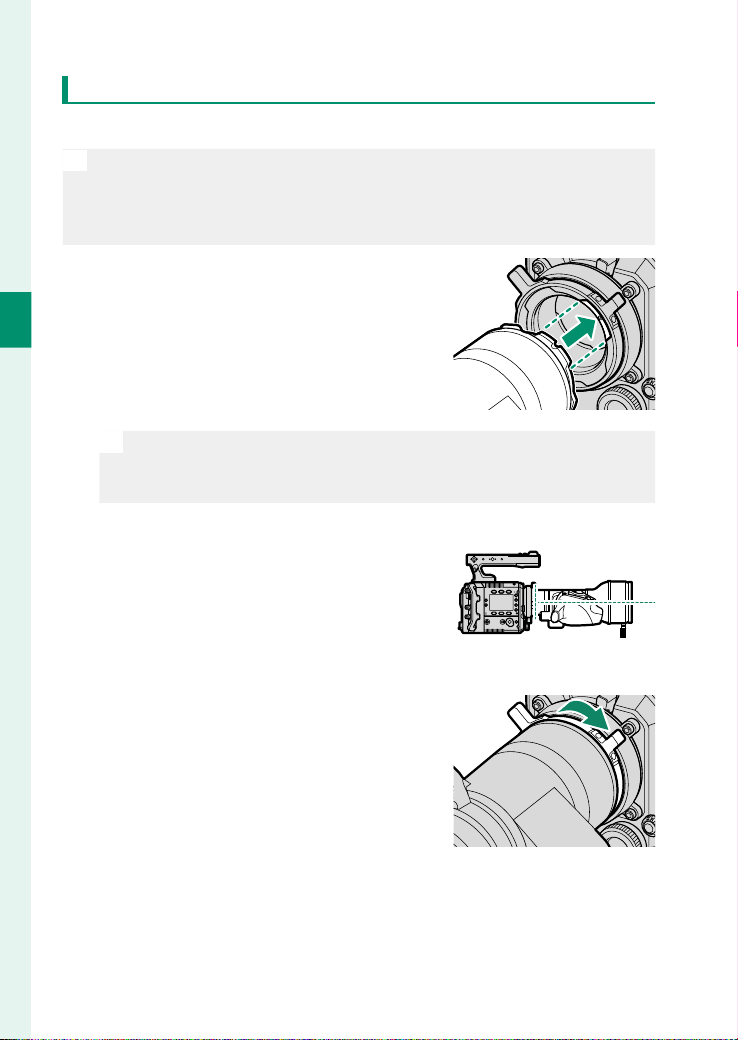
50
2
First Steps
Attaching the PL-mount Lenses
Attach the lens to the PL-mount adapter.
O
When attaching a heavy lens (2 kg or more), use an optional lens sup-
port. Using a lens support will prevent the weight of the lens from af-
fecting the ange focal length and will also reduce the load on the lens
mount (P 200).
1
Attach the lens straight to the cam-
era so that the pin on the PL-mount
adapter aligns with the notch on the
lens.
O
Do not rotate the lens while it is pushed at an angle or it is at-
tached to the PL-mount adapter. Failure to observe this precaution
could damage the signal contacts.
2
Check that the lens is level when
viewed from the side, and rotate the
PL lock levers as shown in the gure
to lock the lens.
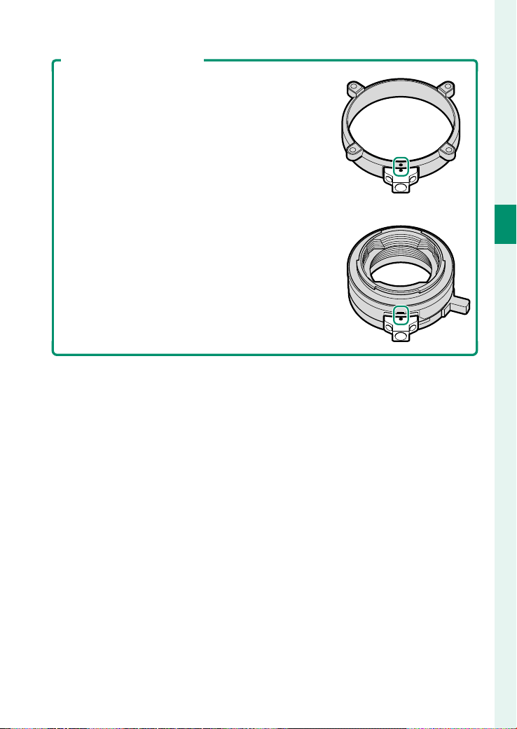
51
2
First Steps
Attaching a Lens
Attaching the Support Frame
After removing the support frame of the
PL-mount adapter cover, when attaching it to
the PL-mount adapter cover again, align the
indicator on the support frame and the mark
on the PL-mount adapter cover and tighten the
bolts using the supplied hex wrench (2 mm).
When using a torque wrench, set the torque to
0.36N·m.
When attaching the support frame to the
mount adapter, align the indicator on the sup-
port frame and the mark on the mount adapter
and tighten the bolts using the supplied hex
wrench (2mm). When using a torque wrench,
set the torque to 0.36N·m.
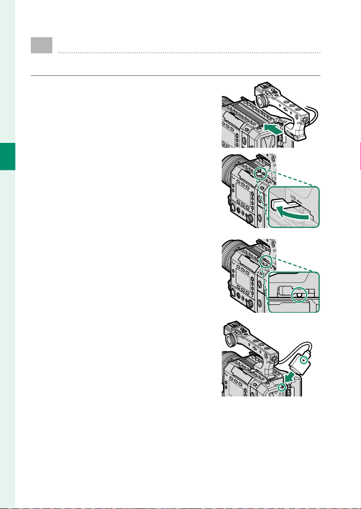
52
2
First Steps
Attaching the Handle
Attach the supplied handle to the camera.
1
Slide the handle into the groove on
the handle attachment mount and
attach it to the camera.
2
Move the lock lever in the direction
of LOCK to lock the handle.
If the handle does not stay securely
in place even after moving the lock
lever, turn the lock lever adjustment
screw for adjustment.
3
Connect the handle cable to the
camera's handle connection termi-
nal, aligning the indicators.
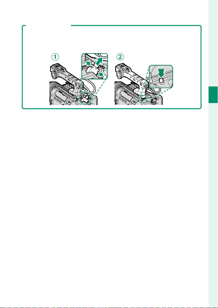
53
2
First Steps
Attaching the Handle
Removing the Handle
While pressing both sides of the handle cable terminal, remove the handle
cable terminal from the handle connection terminal (
A
). After unlocking
the lock lever, slide the handle while pressing the release button (
B
).
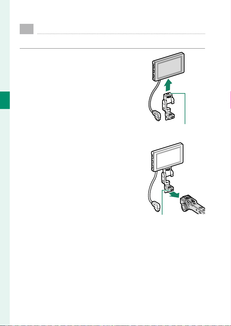
54
2
First Steps
Attaching the LCD Monitor
Attach the supplied LCD monitor to the camera.
1
Attach the LCD attachment to the
accessory mounting screw hole (1/4-
20UNC) on the LCD monitor.
Screw (1/4-20UNC)
2
Attach the LCD attachment to the
accessory mounting screw hole (3/8-
16UNC) on the camera or handle.
Screw (3/8-16UNC)
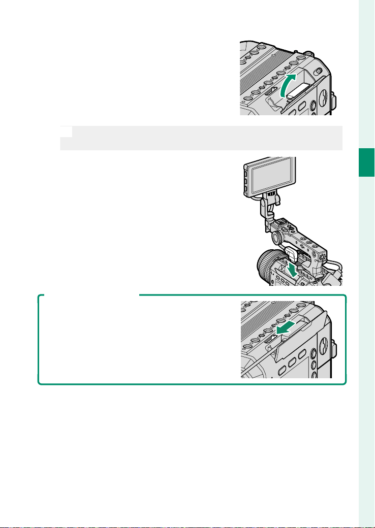
55
2
First Steps
Attaching the LCD Monitor
3
Remove the LCD cable terminal cover
of the LCD cable connector.
N
Keep the removed cover to protect the connectors. If you lose it,
use the supplied spares.
4
Connect the LCD cable to the cam-
era's LCD cable connector.
Removing the LCD Monitor
Slide the LCD cable release lever to disconnect
the LCD cable, and then remove the LCD moni-
tor.

56
2
First Steps
Turning the Camera On and O
Slide the ON/OFF switch to the b
side to turn on the camera. Slide
the ON/OFF switch to the a side to
turn o the camera.

57
2
First Steps
Checking the Supplied Battery Level
Check the battery level of the supplied battery in the dis-
play.
The battery level indicator displayed on the screen shows the re-
maining battery level of the supplied battery.
Indicator
Indicator
Description
Description
e
The battery level is suffi cient.
f
The battery level is about 80%.
g
The battery level is about 60%.
h
The battery level is about 40%.
i
The battery level is about 20%.
i
(red)
The battery level is low. Charge as soon as possible.
j
(red)
The battery is empty. Turn camera off and recharge supplied
battery.
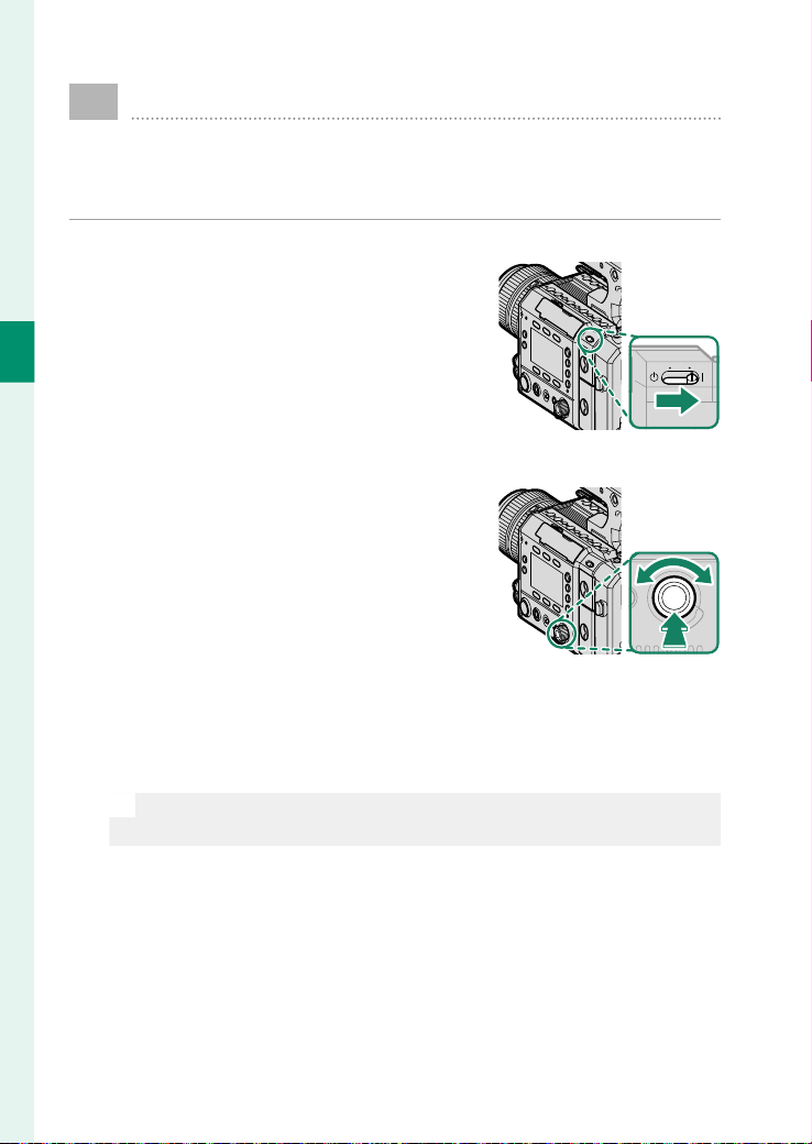
58
2
First Steps
Basic Setup
When you turn the camera on for the rst time, you can
choose a language and set the camera clock. Follow the
steps below when turning the camera on for the rst time.
1
Turn the camera on.
A language-selection dialog will be
displayed.
2
Choose a language.
Rotate the selector dial to highlight a
language and press the center of the
selector dial.
3
Choose a time zone.
Rotate the selector dial to choose a time zone and press the
center of the selector dial.
N
Press ON / OFF (Screen button 6) to enable or disable daylight sav-
ings time.

59
2
First Steps
Basic Setup
4
Set the clock.
Press the center of the selector dial to proceed to the next
step. Press the center of the selector dial on the last step or
press DONE (Screen button 6) to display the HOME options
on the side monitors and the shooting display on the LCD
monitor.
N
If the supplied battery is removed for an extended period, the camera
clock may be reset. In that case, the initial setting screen will be dis-
played, so con gure the settings again.

60
2
First Steps
Basic Setup
Choosing a Di erent Language
To change the language:
1
Display language options.
Select SET UP >
Q
Q
a .
2
Choose a language.
Rotate the selector dial to highlight a language.
3
Press the center of the selector dial.
The display will switch to the selected language.
Changing the Time and Date
To set the camera clock:
1
Display DATE/TIME options.
Select SET UP > DATE/TIME .
2
Set the clock.
Set the display order (year, month, day), date, and time.
3
Press the center of the selector dial on the last item or press
DONE (Screen button 6) to set the date and time.

61
Basic Shooting and Playback

62
3
Basic Shooting and Playback
Recording Movies
1
Turn the camera on (P 56).
2
Press the REC button to start movie
recording and the button will light in
red.
3
Press the REC button again to stop movie recording and the
button will turn o .
O
•
Sound is recorded via the built-in microphone or an optional external
microphone. Do not cover the microphone during recording
(P 3, 4).
•
Note that the microphone may pick up lens noise and other sounds
made by the camera.
•
Vertical or horizontal streaks may appear in movies containing very
bright subjects. This is normal and does not indicate a malfunction.

63
3
Basic Shooting and Playback
Recording Movies
Temperature Warnings
The camera automatically turns o to protect itself when its temperature
or the temperature of the supplied battery rises. If a temperature warning
is displayed, clip noise may increase. Turn the camera o and wait for it to
cool before turning it on again.
Using an External Microphone
Sound can be recorded with external microphones. Use external micro-
phones that connect using jacks 3.5 mm in diameter. Microphones that
require plug-in power should operate at a voltage of 2 V or less. See the
microphone manual for details.
XLR Microphone Adapters
The camera can be used with TEAC TASCAM CA-XLR2d-F XLR microphone
adapters. For more information, visit the TASCAM website.
https://tascam.jp/int/product/ca-xlr2d/#CA-XLR2d_Website

64
3
Basic Shooting and Playback
Viewing Movies
1
Press the PLAY button.
•
A list of les will be displayed on the
side monitors.
•
A preview of the le will be dis-
played on the LCD monitor.
2
Rotate the selector dial to select the clip you want to play.
Rotate the selector dial to the left to move the cursor up. Ro-
tate it to the right to move the cursor down.
N
Press m/n (Screen button 6) to switch between memory cards
for playback.
3
Press the center of the selector dial to play the clip.
Press the BACK button to stop playback.
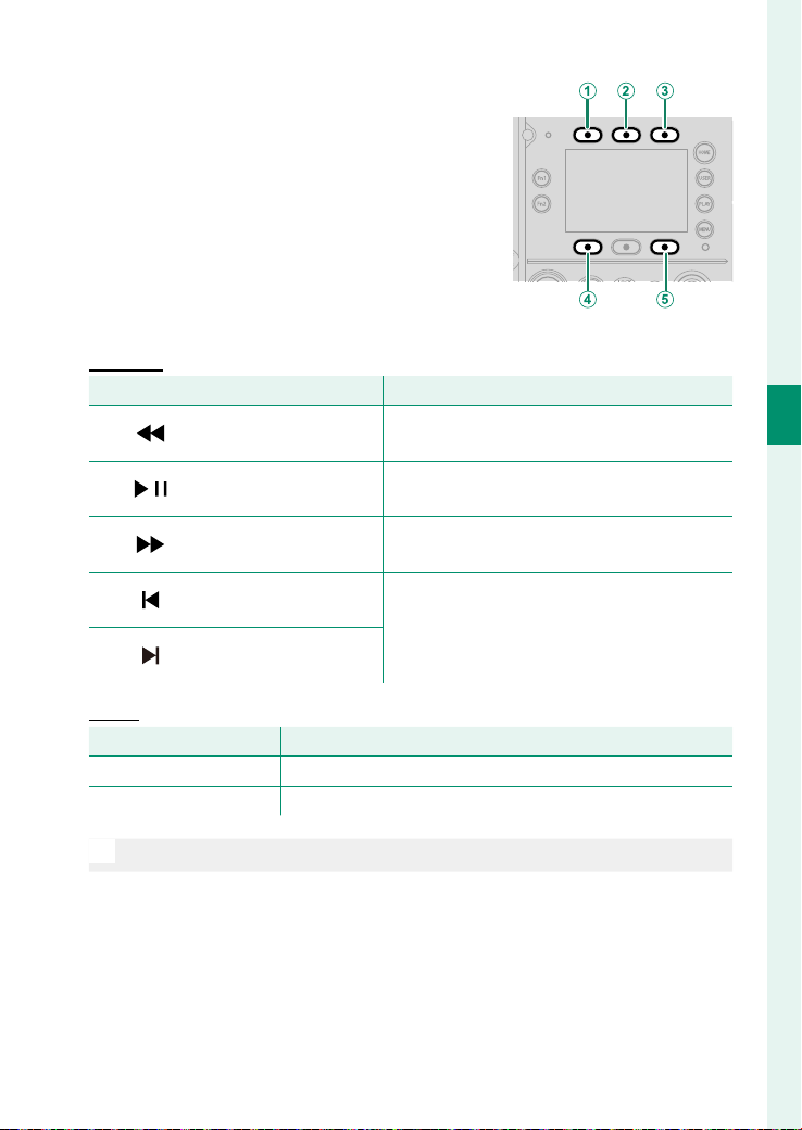
65
3
Basic Shooting and Playback
Viewing Movies
Press the screen buttons during clip
playback to operate the playback.
Playback
Playback
Button
Button
Description
Description
A
A
Rewind
Rewind
(Screen button 1)
(Screen button 1)
Rewind. Also, press the button again during
rewind to change the speed.
B
B
Playback/Pause
Playback/Pause
(Screen button 2)
(Screen button 2)
Pause the playback. Press the button again
to resume playback.
C
C
Advance
Advance
(Screen button 3)
(Screen button 3)
Advance. Also, press the button again dur-
ing advance to change the speed.
D
D
View previous le
View previous le
(Screen button 4)
(Screen button 4)
View the previous or next fi le.
E
E
View next le
View next le
(Screen button 6)
(Screen button 6)
Pause
Pause
Selector dial
Selector dial
Description
Description
Rotate to the right
Rotate to the right View next frame (forward by one frame)
Rotate to the left
Rotate to the left View previous frame (reverse by one second)
O
Do not cover the speaker during playback.

66
3
Basic Shooting and Playback
Saving Still Images
Grab frames from a movie and save them as still images.
Press the GRAB button while movie re-
cording, displaying a through image, or
playing a movie.
The LCD monitor display will be hidden
while a through image is being saved.
N
•
When playing a clip on the playback display, a still image of the movie
being played is saved. When there is no clip to play or a still image is
being displayed, a still image will not be saved.
•
The size of still images saved while displaying a through image or
playing a movie will be the size set in PROJECT > RESOLUTION . The
size of still images saved during movie recording will be equivalent
to FHD.
•
Even if you press the GRAB button during movie recording, movie re-
cording will continue.

67
3
Basic Shooting and Playback
Playing Saved Still Images
1
Press the PLAY button.
A list of les will be displayed on the
side monitors.
2
Press MOVIE / STILL (Screen button4) to display still images
on the LCD monitor.
A list of still images will be displayed on the side monitors.
Rotate the selector dial to select a still image to be displayed.
N
Press m/n (Screen button 6) to switch between memory cards
for playback.

68
MEMO

69
Shooting Settings

70
4
Shooting Settings
Recording Frame Rate
1
Press HOME in shooting mode.
The HOME options will be displayed
on the side monitors.
2
Press FPS (Screen button1).
The recording frame rate settings will be displayed.
3
Rotate the selector dial to highlight a frame rate and press
the center of the selector dial.
Select a frame rate faster than the project frame rate to re-
cord a slow motion movie. Select a frame rate slower than
the project frame rate to record a quick motion movie.
N
Press SDI/HDMI (Screen button 6) to select whether the frame
rate of the movie output to the SDI or HDMI connector should be
the project FPS or the recording frame rate.

71
4
Shooting Settings
ISO Sensitivity
1
Press HOME in shooting mode.
The HOME options will be displayed on the side monitors.
2
Press ISO (Screen button 2).
The sensitivity settings will be displayed.
3
Rotate the selector dial to highlight a sensitivity and press
the center of the selector dial.
Select AUTO to let the camera automatically set the sensitiv-
ity.

72
4
Shooting Settings
Shutter
1
Press HOME in shooting mode.
The HOME options will be displayed on the side monitors.
2
Press SHUTTER (Screen button3).
The shutter angle settings will be displayed.
3
Rotate the selector dial to highlight a shutter angle and press
the center of the selector dial
N
•
Press ANGLE / SPEED (Screen button4) to switch between shut-
ter angle and shutter speed.
•
Press NORMAL / EXPANDED (Screen button 6) to switch the
amount of shutter angle/speed adjustment between NORMAL
and EXPANDED . When set to EXPANDED , the shutter angle/speed
can be set more precisely to reduce icker caused by LED lighting
and the like.

73
4
Shooting Settings
ND Filter
Using ND Filter
Enable ND lter to set the ND lter density.
1
Press HOME in shooting mode.
The HOME options will be displayed on the side monitors.
2
Press ND (Screen button4).
The ND lter settings will be displayed.
3
Press ON / CLEAR (Screen button4).
ON will be selected for the ND lter. Press again to select
CLEAR for the ND lter.
4
Rotate the selector dial to highlight a density and press the
center of the selector dial.
N
•
Press DENSITY / FACTOR (Screen button6) to change the ND l-
ter density display to lter factor.
•
You can also use the multi-function dial to set the density
(P 14).

74
4
Shooting Settings
Look
Set whether to apply the LUTs (Lookup Tables) set for each
footage of the memory card, LCD monitor display, and SDI/
HDMI output to the output footage.
Setting LUTs
Navigate to PROJECT > LUT SETTING to select the LUT to apply
to each type of footage. LUT settings recorded on the memory
card can also be loaded into the camera for use.
N
The types of video output to the memory card, LCD monitor, SDI OUT
connector, and HDMI OUT connector can be changed in PROJECT >
F-Log/HLG/RAW .

75
4
Shooting Settings
Look
Applying to Footage
Set whether to apply the con gured LUTs to each footage.
1
Press HOME in shooting mode.
The HOME options will be displayed on the side monitors.
2
Press Screen button 5.
Combinations are displayed regarding whether to apply
LUTs to each output. The LUTs will be applied to the outputs
to which LOOK is set. The LUTs will not be applied to the out-
puts to which CLEAN is set.
The available combinations are as follows:
Option
Option
Description
Description
A
A The LUTs will be applied only on the LCD monitor display.
B
B
The LUTs will be applied to all of the memory card, LCD moni-
tor, and SDI/HDMI outputs.
C
C
The LUTs will not be applied to any of the memory card, LCD
monitor, or SDI/HDMI outputs.
3
Rotate the selector dial to highlight a combination of set-
tings and press the center of the selector dial.
N
•
Press LUT (Screen button 4) to adjust the LUT SETTING .
•
Press CHECK (Screen button 6) to adjust settings for SDI/HDMI
OUTPUT INFO DISPLAY . When ON is selected for SDI/HDMI
OUTPUT INFO DISPLAY , the SDI/HDMI output will have the
same settings as the LCD monitor, regardless of the selected
combination.

76
4
Shooting Settings
White Balance
The white balance for movie can be set using either auto
white balance, custom white balance, or preset white bal-
ance.
Auto White Balance
The camera automatically adjusts the white balance according
to scene changes.
1
Press HOME in shooting mode.
The HOME options will be displayed on the side monitors.
2
Press WB (Screen button6).
The white balance settings will be displayed.
3
Press AWB SET (Screen button3).
The auto white balance settings will be displayed.
4
Rotate the selector dial to highlight a setting and press the
center of the selector dial.
The Type of Auto White Balance
The available auto white balance settings are as follows:
Option
Option
Description
Description
WHITE PRIORITY
WHITE PRIORITY
Choose for whiter whites in scenes lit by incandescent
bulbs.
AUTO
AUTO Standard auto white balance.
AMBIENCE PRIORITY
AMBIENCE PRIORITY
Choose for warmer whites in scenes lit by incandescent
bulbs.

77
4
Shooting Settings
White Balance
Custom White Balance
When you shoot a subject that serves as a reference for white
balance, such as white paper, the camera automatically sets the
white balance.
1
Press HOME in shooting mode.
The HOME options will be displayed on the side monitors.
2
Press WB (Screen button6).
The white balance settings will be displayed.
3
Press CWB SET (Screen button1).
The custom white balance settings will be displayed.
4
Display a subject, such as white paper, on the screen.
N
You can also change the size and position of the area for obtaining
a custom white balance.
5
Press the REC button.
•
COMPLETE will be displayed when the white balance is set
correctly.
•
If OVER is displayed, lower exposure compensation.
•
If UNDER is displayed, raise exposure compensation.

78
4
Shooting Settings
Preset White Balance
Select a preset color temperature and manually set the white
balance.
Adding or Editing Preset White Balance Settings
Add new preset white balance settings or edit existing ones.
1
Press HOME in shooting mode.
The HOME options will be displayed on the side monitors.
2
Press WB (Screen button6).
The white balance settings will be displayed.
3
Press WB ADD (Screen button6).
The color temperature settings will be displayed.
N
Press WB EDIT (Screen button5) to edit existing preset white bal-
ance settings.
4
Rotate the selector dial to select color temperature.
•
Press the center of the selector dial to move to the next
digit. Press the BACK button to return to the previous digit.
•
Press K / CC (Screen button5) to set CC.
5
Press DONE (Screen button6).

79
4
Shooting Settings
White Balance
Deleting Preset White Balance Settings
Delete existing preset white balance settings.
1
Press HOME in shooting mode.
The HOME options will be displayed on the side monitors.
2
Press WB (Screen button6).
The white balance settings will be displayed.
3
Select the preset you want to delete, then press WB
DELETE (Screen button4).
A con rmation dialog for the deletion will be displayed.
4
Press two DELETE (Screen buttons4 and 6) simultaneously.
The selected preset will be deleted.

80
4
Shooting Settings
Autofocus
Rotate the focus mode selector to AF to record using auto-
focus.
AF MODE
Use FOCUS > AF MODE to choose how
the camera focuses. Use the focus stick
(focus lever) on the handle to select the
position of the focus area and the sub-
ject.
MULTI
The camera selects the focus area automatically.
TRACKING
Press the focus stick (focus lever) to the center to automatically
track focus on the subject in the focus area. Press the button
again to stop tracking.
AREA
The camera focuses on the subject in the selected focus area.
N
•
You can also tap the LCD monitor to change the focus area position
or the subject to focus.
•
If you are using a lens that allows focus method settings on the lens
side, set the lens’s focus mode switch to S beforehand.

81
4
Shooting Settings
Autofocus
FOCUS AREA
Use FOCUS > FOCUS AREA to set the position to focus on for
TRACKING or AREA . You can also press the BACK button to return
the focus area to the center.
N
You can also tap the LCD monitor to change the focus area position.

82
4
Shooting Settings
Manual Focus
Rotate the focus mode selector to MF to record using man-
ual focus.
When using manual focus, adjust the focus in the following ways:
Focus Ring
Focus manually using the lens focus ring.
Multi-Function Dial/Function Buttons
You can use the multi-function dial or function buttons to adjust
the focus.
N
If you are using a lens that allows focus method settings on the lens
side, set the lens’s focus mode switch to S beforehand.
Multi-Function Dial
Set the multi-function selector dial to F and then rotate the multi-
function dial to adjust the focus (P 14).
N
You can also use the multi-function dial to adjust the focus when ON
is selected for AF+MF .
Function Buttons
Press the function buttons to which F CONSTANT SPEED
FOCUS (N) or F CONSTANT SPEED FOCUS (F) is assigned to ad-
just the focus (P 181).

83
4
Shooting Settings
Iris
Aperture Ring
You can adjust the iris using the aperture ring when using a lens
with an aperture ring.
Recording Setting
Use RECORDING > IRIS to adjust the iris. If AUTO is selected, the
camera automatically adjusts the iris.
Multi-Function Dial
While RECORDING > IRIS is set to an option other than AUTO ,
when a lens with no aperture rings is used or when the lens ap-
erture ring is in the C position, you can adjust the iris by setting
the multi-function selector dial to I and then rotating the multi-
function dial (P 14).
Function Buttons
Press the function buttons to which IRIS + or IRIS- (OPEN) is as-
signed to adjust the iris. Press the function buttons to which IRIS
AUTO is assigned to toggle whether the camera automatically
adjusts the iris (P 181).

84
4
Shooting Settings
Zoom
Zoom Ring
Rotate the lens zoom ring to operate the zoom.
Power Zoom
When using a compatible power zoom lens, use the following
methods to operate the zoom. Set the lens’s zoom mode switch
to S beforehand.
Multi-Function Dial
When using a compatible power zoom lens, set the multi-func-
tion selector dial to Z and then rotate the multi-function dial to
operate the zoom (P 14).
Zoom Lever
When using a compatible power zoom lens, press the zoom lever
on the handle to operate the zoom. The zoom speed changes
depending on how far you press the zoom lever.
Function Buttons
When using a compatible power zoom lens, press the function
buttons to which CONSTANT SPEED ZOOM (T) or CONSTANT
SPEED ZOOM (W) is assigned to operate the zoom (P 181).
N
Use ZOOM/FOCUS SETTING > CONSTANT SPEED(Fn) in the USER to
adjust the zoom speed when using the zoom button.

85
4
Shooting Settings
Photometry
RECORDING > PHOTOMETRY o ers a choice of the follow-
ing metering options:
O
The selected option will only take e ect if FOCUS > SUBJECT
DETECTION SETTING is disabled.
Mode
Mode
Description
Description
o
MULTI
MULTI
The camera instantly determines exposure based on an
analysis of composition, color, and brightness distribution.
Recommended in most situations.
p
CENTER WEIGHTED
CENTER WEIGHTED
The camera meters the entire frame but assigns the greatest
weight to the area at the center.
v
SPOT
SPOT
The camera meters lighting conditions in an area equivalent
to 2% of the frame. Recommended with backlit subjects and
in other cases in which the background is much brighter or
darker than the main subject.
w
AVERAGE
AVERAGE
Exposure is set to the average for the entire frame. Provides
consistent exposure regardless of composition or subjects,
and is particularly eff ective for landscapes and portraits of
subjects dressed in black or white.

86
4
Shooting Settings
Touch Screen Mode
With this camera, the LCD monitor functions as a touch
screen.
LCD Monitor Touch Controls
When ON is selected for TOUCH SCREEN SETTING > TOUCH
SCREEN(LCD) or PLAY BACK SETTING(LCD) in USER , the follow-
ing touch controls can be used in shooting and playback modes:
N
Only swiping is available during movie playback.
Swipe
Swipe a nger across the display to view
other les.
Double-Tap
Tap the display twice to zoom in on the
focus point.
N
When tapping the display twice to zoom in shooting mode, TOUCH
SCREEN SETTING > DOUBLE TAP SETTING(LCD) in USER must be
enabled beforehand.

87
4
Shooting Settings
Touch Screen Mode
Selecting a Focus Area
When AF is selected for FOCUS > TOUCH SCREEN MODE , you can
reposition the focus area at any time by tapping your subject on
the LCD monitor in shooting mode.
N
When
AREA
is selected for FOCUS > TOUCH SCREEN MODE , the
focus area will move to the selected point, but the focus will not be
adjusted.
Focus Zoom
When HIGH is selected for TOUCH SCREEN SETTING > DOUBLE
TAP SETTING(LCD) in USER , tap the center of the screen twice to
enlarge the center of the shooting screen by 6 x. When LOW is se-
lected, it will be enlarged by 2.5 x. Tap the center twice again to
return to the original display.

88
MEMO

89
Playback and the Playback
Menu

90
5
Playback and the Playback Menu
The Playback Display
The following information is displayed on the side moni-
tors and LCD monitor during playback.
O
For illustrative purposes, displays are shown with all indicators lit.
Side Monitors
Display When Selecting a File to Play
2025
SETTING
STILLMOVIE
CLIP LIST
A B C D
E
F
G
HQ
P
K
M
O
N
L
J
I
A
Temperature warning ......................40, 230
B
Frame.io connection status ...................104
C
Frame.io upload progress .......................103
D
External power source ............................... 37
E
W235 battery mode ................................... 34
F
NP-W235 battery level .............................. 57
G
Frame size ...................................................119
H
Recording frame rate ................................. 70
I
Codec............................................................125
J
FS/F-Log/HLG ....................................120, 122
K
Time code ....................................................146
L
Recording time
M
Recording date and time .................58, 171
N
File number/ total number of fi les
O
Media
P
File format ...................................................124
Q
Project frame rate .....................................119
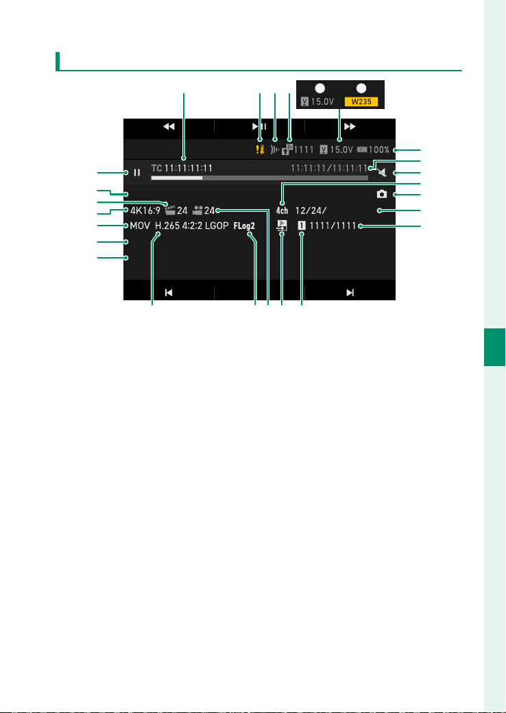
91
5
Playback and the Playback Menu
The Playback Display
Display During File Playback
ETERNA_BT.709_AAA...LUT
GF35.0 -70.0mm F4.5 - 5.6LENS
A_0001C0005_240208_113020_p3W200125
SETTING
PLAYBACK
2025
BA C D
E
F
G
I
K
L
M
H
J
NOQ PR
S
T
U
V
X
Y
W
A
Time code ....................................................146
B
Temperature warning ......................40, 230
C
Frame.io connection status ...................104
D
Frame.io upload progress .......................103
E
External power source ............................... 37
F
W235 battery mode ................................... 34
G
NP-W235 battery level .............................. 57
H
Playback time/ recording time
I
Mute
J
Four-channel (quadrophonic) audio
recording .................................................. 144
K
Grab ................................................................66
L
Recording date and time .................58, 171
M
File number/ total number of fi les
N
Card slot
O
Frame.io fi le transfer order
P
Recording frame rate ................................. 70
Q
FS/F-Log/HLG ....................................120, 122
R
Codec............................................................125
S
LUT fi le
T
Lens information
U
File format ...................................................124
V
Frame size ...................................................119
W
Project frame rate .....................................119
X
Clip name
Y
Playback status
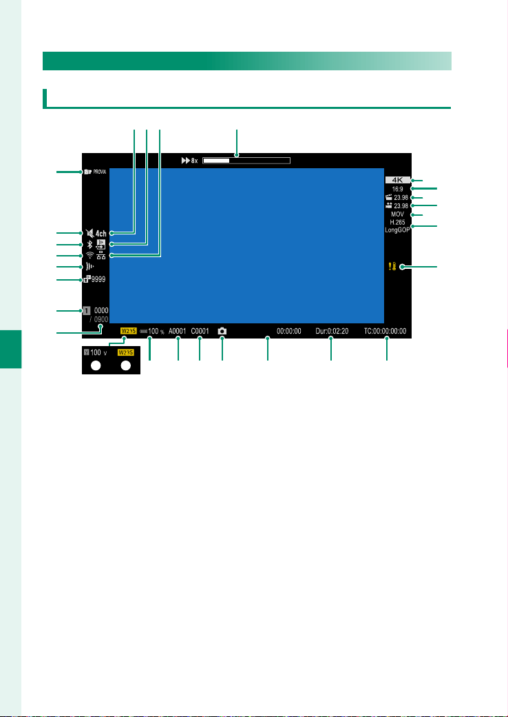
92
5
Playback and the Playback Menu
LCD Monitor
Display During Movie Playback
12/31/2025
D
F
E
H
G
J
I
K
LMNOPQR
ST
V
W
X
Y
Z
a
b
U
A B C
A
Four-channel (quadrophonic) audio
recording .................................................. 144
B
Frame.io fi le transfer order
C
Ethernet connection
D
Playback status
E
Resolution ................................................... 119
F
Aspect ratio.................................................119
G
Recording frame rate ................................. 70
H
Project frame rate .....................................119
I
File format ...................................................124
J
Codec............................................................125
K
Temperature warning ......................40, 230
L
Time code ....................................................146
M
Recording time
N
Recording date and time .................58, 171
O
Grab ................................................................66
P
Clip No.
Q
Reel No. ........................................................126
R
NP-W235 battery level .............................. 57
S
W235 battery mode ................................... 34
T
External power source ............................... 37
U
File number/ total number of fi les
V
Card slot
W
Frame.io upload progress .......................103
X
Frame.io connection status ...................104
Y
Wireless connection
Z
Bluetooth ON/OFF
a
Mute
b
LOOK media FS/F-Log/HLG ...................120
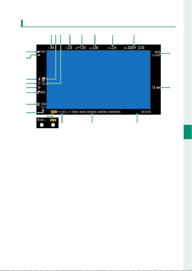
93
5
Playback and the Playback Menu
The Playback Display
Display During Still Image Playback
+1
12/31/2025
A D E F G H
C
Q
R
S
T
U
W
V
P
B
M
NO
I
J
KL
A
Shutter speed ............................................... 72
B
Frame.io fi le transfer order
C
Ethernet connection
D
Aperture ......................................................... 83
E
Exposure compensation .........................127
F
Sensitivity ...................................................... 71
G
ND (Neutral Density) fi lter indicator ..... 73
H
White balance ............................................. 76
I
Image size
J
Temperature warning ......................40, 230
K
Recording date and time .................58, 171
L
File name
M
NP-W235 battery level .............................. 57
N
W235 battery mode ................................... 34
O
External power source ............................... 37
P
File number/ total number of fi les
Q
Card slot
R
Frame.io upload progress .......................103
S
Frame.io connection status ...................104
T
Wireless connection
U
Bluetooth ON/OFF
V
Noise reduction
W
Film simulation/F-Log/
HLG recording ................................120, 122

94
5
Playback and the Playback Menu
The Playback Display
Switching Information Display
Press DISP to enable or disable the information display.

95
5
Playback and the Playback Menu
The Playback Menu
Adjust playback settings for clips.
SDI/HDMI OUTPUT SETTING
Set whether to output the playback display to the external out-
put connectors.
SDI OUTPUT SETTING
Set whether to output the playback display to the SDI OUT con-
nector.
Options
Options
ON
ON
OFF
OFF
HDMI OUTPUT
Set whether to output the playback display to the HDMI OUT
connector.
Options
Options
ON
ON
OFF
OFF
SDI/HDMI OUTPUT RESOLUTION
Set the resolution of the footage output to the SDI OUT and
HDMI OUT connectors.
Options
Options
8K
8K
4K
4K
4K DCI
4K DCI
FHD
FHD
N
This is a common setting with SDI/HDMI OUTPUT SETTING > SDI/
HDMI OUTPUT RESOLUTION in MONITOR SETTING .

96
5
Playback and the Playback Menu
The Playback Menu
VOLUME
Adjust the volume for movie playback.
Options
Options
012345678910
4ch AUDIO PLAYBACK
Adjust audio settings for use when viewing 4ch clips.
Option
Option
Description
Description
XLR
XLR
The camera plays audio recorded via external microphones
connected via the XLR microphone adapter.
CAMERA
CAMERA
The camera plays audio recorded via the camera’s built-in
microphone or external microphones connected via the
microphone connector.
N
You can also switch sources while viewing the playback display by
pressing the Fn5 button.
DESQUEEZE DISP. IN PLAYBACK
You can con gure whether to use the desqueeze display when
playing back clips recorded with anamorphic lenses.
Options
Options
ON
ON
OFF
OFF

97
Network Connection
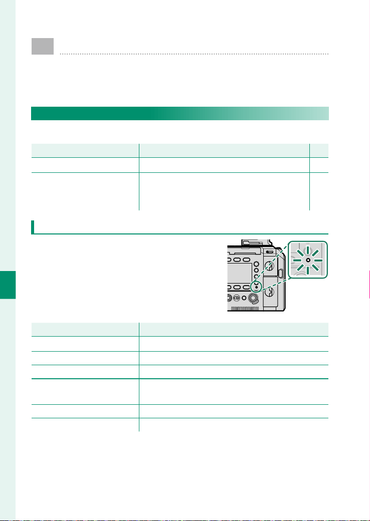
98
6
Network Connection
Overview
This chapter outlines features that can among other things
be used to upload clips to, or control the camera and take
clips remotely from, a smartphone or computer.
Supported Features
This camera supports the following features:
Feature
Feature
Description
Description
P
P
Upload to Frame.io
Upload to Frame.io Upload fi les to Frame.io. 103
Remote movie recording
Remote movie recording
Control the camera and record movies re-
motely using a web browser on a computer
or tablet.
105
Camera Indicator Lamp Display
The camera indicator lamp shows the
status of its connection to Frame.io and
the like.
Indicator lamp
Indicator lamp
Connection status
Connection status
Blinks red
Blinks red No network connection.
Glows red
Glows red No network connection; fi les awaiting upload.
Blinks orange Connected to network but not to Frame.io.
Blinks orange and red
Connected to network but not to Frame.io; fi les
awaiting upload.
Blinks green Ready for upload to Frame.io.
Blinks green and red Ready for upload to Frame.io; fi les awaiting upload.

99
6
Network Connection
Connecting to the Network
When using network functions, you must con gure the
settings for network connection in advance.
Connecting via Wireless LAN
N
You cannot connect to a network in the following cases:
•
When the wireless LAN function is turned o .
•
When the camera is powered only by the supplied battery.
Connecting to a Detected Network
Select a network from those that the camera automatically de-
tected to connect to.
1
Select NETWORK > WIRELESS LAN .
2
A list of automatically detected networks is displayed.
Select the network you want to connect to.
N
•
Press ON / OFF (Screen button 4) to enable or disable the wireless
LAN function.
•
Press ADD (Screen button 6) to connect to a network that is not
displayed (P 100).
3
Enter the network password.
4
The camera connects to the network.

100
6
Network Connection
Connecting to a Registered Network
Networks once connected will be registered on the camera. Se-
lect a registered network to connect to or adjust the settings.
1
Select NETWORK > WIRELESS LAN .
2
A list of automatically detected networks is displayed.
Select a registered network.
3
Select CONNECT TO NETWORK .
N
•
Select PASSWORD to change the registered password.
•
Select IP ADDRESS SETTING to switch between automatic
and manual IP address assignment. For manual assignment, use
MANUAL IP ADDRESS SETTING to enter the IP address, subnet
mask, gateway, and DNS server information.
•
Select DELETE NETWORK to delete the registration information
for the selected network.
4
The camera will be connected to the network.
Connecting to a Network Manually
Manually register network information and connect to networks
that do not appear on the automatic detection list.
1
Select NETWORK > WIRELESS LAN .
2
A list of automatically detected networks is displayed.

101
6
Network Connection
Connecting to the Network
3
Press ADD (Screen button 6).
N
Press ON / OFF (Screen button 4) to enable or disable the wireless
LAN function.
4
The method for adding a network is displayed.
Select ENTER SSID AND ADD .
N
Select ADD USING WPS BUTTON to press the WPS button on the
wireless LAN router and connect to the network.
5
Select SSID to enter the SSID.
Enter the network SSID on the input screen.
6
Select PASSWORD to enter the password.
Enter the network password on the input screen.
7
Set the IP address assignment method.
•
Select AUTO to allow the camera to automatically obtain
an IP address.
•
When MANUAL is selected, use MANUAL IP ADDRESS
SETTING to enter the IP address, subnet mask, gateway,
and DNS server information.
8
Select DONE .
The camera will be connected to the network.

102
6
Network Connection
Connecting to the Network
Connecting via Wired LAN
N
The camera cannot be connected to a network when the camera is
powered only by the supplied battery.
1
Connect the camera to a network using a LAN cable.
2
Select NETWORK > WIRED LAN SETTING .
3
Set the IP address assignment method.
•
Select AUTO for IP ADDRESS SETTING to allow the camera
to automatically obtain an IP address.
•
When MANUAL is selected for IP ADDRESS SETTING , use
MANUAL IP ADDRESS SETTING to enter the IP address,
subnet mask, gateway, and DNS server information.
4
The camera will be connected to the network.

103
6
Network Connection
Uploading Files to Frame.io
Upload les to Frame.io (P 206).
N
Con rm that the camera clock is set to the correct time and date be-
fore proceeding.
Connecting to Frame.io
1
Connect the camera to a network (P 99).
2
Select NETWORK > Frame.io Camera to Cloud .
N
The rst time you start up Frame.io, a screen introducing its fea-
tures will be displayed. Press CLOSE (Screen button5) to proceed
to the next screen.
3
Select CONNECT .
4
Select CONNECT from the options CONNECT or DISCONNECT .
5
Select GET PAIRING CODE .
A pairing code will be displayed.
6
Sign in to Frame.io from a computer or other device and en-
ter the pairing code displayed on the camera.

104
6
Network Connection
Uploading Files to Frame.io
Uploading Files to Frame.io
Uploading Files as They Are Taken
Files shot with ON selected for UPLOAD SETTING > AUTO IMAGE
TRANSFER ORDER in Frame.io Camera to Cloud are automati-
cally marked for upload.
Selecting Files for Upload During Playback
Press the Fn1 or Fn3 button on the playback display to schedule
or cancel uploads.
Connection Status
The connection status with Frame.io can be checked by the icon displayed on the
side monitors.
Icon
Icon
Connection status
Connection status
(white)
(white)
Connected to Frame.io.
(gray)
(gray)
Not connected to Frame.io.
(red)
(red)
Frame.io server has set camera status to “paused”. To re-
store connection, clear “paused” status using a computer
or other device.
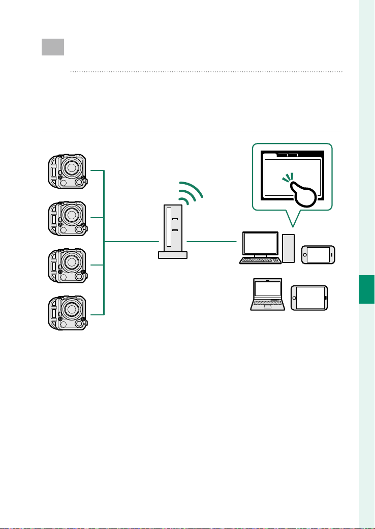
105
6
Network Connection
Remote Movie Recording Using a Web
Browser
The camera supports remote movie recording. You can
connect to up to four cameras using a web browser on a
computer or tablet and record movies or adjust camera
settings.
Wired LAN
(Ethernet)/
wireless LAN
Wired LAN
(Ethernet)/
wireless LAN
Web browser
Computer/tablet

106
6
Network Connection
Con guring the Camera Settings
Con gure settings to connect to the camera from a browser on a
computer or tablet.
1
Select REMOTE REC FUNCTION > USER NAME in NETWORK
to register a user name.
2
Select REMOTE REC FUNCTION > PASSWORD to register a
password.
3
Select REMOTE REC FUNCTION > SERVER TYPE to set a serv-
er type.
N
HTTPS is selected at shipment. Importing a root certi cate into
the browser on your computer or tablet is required when HTTPS
is selected.
4
Connect to the camera from a computer or tablet (P 107).
Connecting via HTTPS
If you selected HTTPS for SERVER TYPE , you will need to import a root
certi cate into the browser on your computer or tablet. Instructions on
downloading and installing a root certi cate are available from the follow-
ing website:
https://fujifilm-dsc.com/en/manual/rootcer/
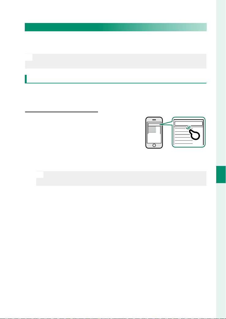
107
6
Network Connection
Remote Movie Recording Using a Web Browser
Connecting to the Camera from a Computer or Tablet
Connect to the camera from a web browser on a computer or
tablet.
N
We recommend using (connecting via) a high-speed access point (for
example, one that operates in the 5GHz band).
Connecting the First Camera
Connect by using a web browser to enter the IP address or using
a camera app to scan the QR code displayed by the camera.
Connecting using an IP address
Connecting using an IP address
1
Launch a web browser on your com-
puter or tablet and enter the cam-
era’s IP address in the address bar.
To connect to a camera with an IP ad-
dress of 192.168.0.11, for example,
enter “http://192.168.0.11”.
XXXXXXXXX.........
N
The camera's IP address can be viewed in NETWORK > REMOTE
REC FUNCTION .
2
An entry screen appears. Enter the user name and password.
The remote recording display will appear in the browser.

108
6
Network Connection
Connecting by scanning a QR code
Connecting by scanning a QR code
1
Select REMOTE REC FUNCTION > QR CODE in NETWORK .
A QR code will be displayed on the side monitors.
2
Launch the camera application on the tablet and scan the
QR code.
The web browser launches, and the remote recording display
appears.
Connecting a Second or Subsequent Camera
Either enter the IP address in the remote recording display in the
web browser or scan the QR code to connect.
N
When you connect a second or subsequent camera, set the same
SERVER TYPE as the rst camera beforehand (P 106).
Connecting using an IP address
Connecting using an IP address
1
Click or tap the thumbnail of the + mark in the “Choose cam-
era” area of the remote recording display.
2
An entry screen appears. Enter the camera’s IP address and
an account name and password.
The remote recording display will appear in the browser.
N
The camera's IP address can be viewed in NETWORK > REMOTE
REC FUNCTION .

109
6
Network Connection
Remote Movie Recording Using a Web Browser
Connecting by scanning a QR code
Connecting by scanning a QR code
N
To connect a second or subsequent camera by scanning a QR code, set
SERVER TYPE of the rst camera and second and subsequent cameras
to HTTPS in advance.
1
Select REMOTE REC FUNCTION > QR CODE in NETWORK .
A QR code will be displayed on the side monitors.
2
Tap the thumbnail of the + mark in the “Choose camera” area.
3
Tap “Connect via QR Code” to scan the QR code displayed by
the camera.
The remote recording display will appear in the browser.
Disconnecting a Second or Subsequent Camera
To end a connection after adding a camera, select the “remove connected
device” option in the “Remote recording” menu and click or tap the thumb-
nail for the camera you want to remove.
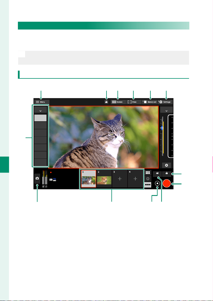
110
6
Network Connection
The Remote Recording Display
The controls available in the remote recording display are de-
tailed below.
N
The display layout varies with the size of the computer or tablet screen,
among other factors.
Overview
GRAB
-20
-40
-50
-6
0
-12
70
%
60
%
50
%
40
%
30
%
20
%
10
%
0
%
10
5.0
3.0
2.0
1.5
1.0
0.5
0.1
m
AF+MF
REC
1 2
3
4
ANAMOR
MOV4K 17:9
23.98 H.265 422 LongGOP
F5.6
REEL A0001
CLIP C0004
REC
00:01:23
00:01:23:45
REC-HOLD
Premista 28-100mm T2.9GFX ETERNA55
FOCUS
IRIS
FOCUS
AF
WAVEFORM
ZOOM
ND
COLOR
LAUNCHER
M
K JL
BA C D E F
G
H
I

111
6
Network Connection
Remote Movie Recording Using a Web Browser
Item
Item
Description
Description
A
A
Remote recording menu
Adjust remote recording settings (P 113).
B
B
Lock button
Lock button
Enable or disable the controls for the selected
cameras or in the remote recording display.
C
C
Screen button
Screen button
Switch the view through the lens of the camera
to a multi-screen view.
D
D
Display mode button Switch displays.
E
E
Check button for movies in
Check button for movies in
memory card
memory card
View the clips on the memory card in the se-
lected camera.
F
F
Camera settings (advanced)
Camera settings (advanced)
Adjust (advanced) settings for the current
camera.
G
G
REC-Hold button
REC-Hold button
Lock the start/stop operation of movie record-
ing.
H
H
REC button
REC button Start movie recording.
I
I
Choose for REC/STOP
Choose for REC/STOP
Choose the camera or cameras to which the
selected action (starting or stopping recording)
will apply.
J
J
STOP button
STOP button Stop movie recording.
K
K
Choose camera
Choose camera
A list of thumbnails showing the views through
the lenses of the connected cameras. Click or
tap a thumbnail to select a camera to control.
L
L
GRAB button
GRAB button Save still images.
M
M
Camera settings
Camera settings Adjust settings for the current camera.
N
If the connection is disconnected while locked, the camera operations
will remain locked. In that case, turn the camera o .
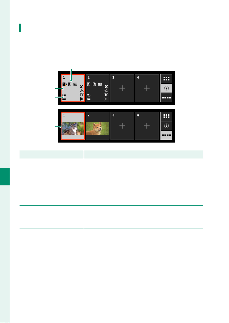
112
6
Network Connection
Choose Camera
The views through the lenses and camera information of the
connected camera are displayed as thumbnails. Click or tap a
thumbnail to select a camera to control.
14.5V
100%
14.4V
100%
2345 min 34 sec
A
B
C
D
Setting
Setting
Description
Description
A
A
Card slot options
Camera storage settings. The icon for the current
slot is shown in orange. The display turns red if the
camera is unable to record to the current card.
B
B
Recording time available
The remaining recording time. When the time
remaining grows short, the thumbnail will flash and
the recording time will be displayed in red.
C
C
Power supply
Power supply
Display the power supply voltage and the remaining
battery level of the supplied battery. The thumbnail
will blink when the supplied battery runs low.
D
D
Thumbnail frame
A frame appears around the thumbnail for the
current camera. Regardless of whether they are cur-
rently selected, cameras that are currently recording
are highlighted in red or, during high-speed record-
ing, in green.

113
6
Network Connection
Remote Movie Recording Using a Web Browser
Remote Recording Menu
Adjust remote recording settings.
Show microphone level
Show microphone level
Hide or view the microphone recording level.
Show tool bar
Show tool bar
Hide or view the browser toolbar.
Clean display mode
Clean display mode
Switch to clean display mode, which displays only the view
through the lens.
Display with Image quality priority/Real-time performance priority
Display with Image quality priority/Real-time performance priority
Choose how you prefer the view through the lens to be dis-
played, giving priority either to image quality or to ensuring that
the picture updates in real time.
N
•
Prioritizing image quality maximizes image quality but may result in
display lag.
•
Prioritizing real-time display keeps display lag to a minimum regard-
less of such factors as connection speed.
Light mode/Dark mode
Light mode/Dark mode
Switch between the light- and dark-mode remote recording dis-
plays.
Stop the camera connection
Stop the camera connection
Click or tap a thumbnail in the “Choose camera” area to end the
connection to the selected camera.

114
6
Network Connection
Recording Movies Remotely
Start recording on one or more remote cameras or end recording
on selected cameras without ending recording on others.
1
The cameras to which the chosen action (starting or stop-
ping recording) will apply can be selected in the “Choose for
REC/STOP” area.
Select cameras by clicking or tapping the numbers in the
“Choose for REC/STOP” area. The numbers for the selected
cameras will be highlighted.
2
Click or tap the “REC button”.
The selected cameras will start recording and their thumb-
nails will be highlighted in color.
3
To end recording, select the desired cameras in the “Choose
for REC/STOP” area.
Select cameras by clicking or tapping the numbers in the
“Choose for REC/STOP” area. The numbers for the selected
cameras will be highlighted.
4
Click or tap the “STOP button”.
The selected cameras will stop recording.
Viewing Movies
View clips stored on the camera memory card.
1
Select a camera in the “Choose camera” area.
2
Click or tap the “Check button for movies in memory card”.
The les on the camera memory card will be displayed.

115
6
Network Connection
Remote Movie Recording Using a Web Browser
Saving and Loading Camera Settings
Save settings for connected cameras to the computer or tablet or
load previously-saved settings.
Saving Camera Settings
Save camera settings to a settings le on the computer or tablet.
1
Select a camera in the “Choose camera” area.
2
Select “Backup” in the “Camera settings (advanced)” menu.
3
Click or tap “Save settings”.
Settings for the selected camera will be saved to a settings
le on the computer or tablet.
Loading Saved Settings
Load saved settings onto a selected camera.
1
Select a camera in the “Choose camera” area.
2
Select “Restore” in the “Camera settings (advanced)” menu.
3
Select the desired settings le and click or tap “Load settings”.
The settings will be copied to the selected camera.
N
•
The location and procedure for loading les varies with the computer
or tablet.
•
Only les created with cameras of the same type can be used.

116
6
Network Connection
Remote Movie Recording Using a Web Browser
Copying Settings to Other Cameras
Settings can be copied to multiple cameras simultaneously.
1
Select the source camera in the “Choose camera” area.
2
Select “Copy” in the “Camera settings (advanced)” menu.
3
Select the destination cameras and click or tap “Copy”.
The settings currently in e ect on the source camera will be
copied to the destination cameras.
N
Only les created with cameras of the same type can be used.

117
The Menus

118
The Menus
7
PROJECT
Adjust the project setting for movie recording.
IMAGE FORMAT
You can set the format of movies to be shot depending on the
lens to be used.
IMAGE FORMAT
Select the format of movies to be shot depending on the lens
to be used. Resolution and aspect ratio are set by RESOLUTION .
Option
Option
Description
Description
GF
Shoot in the optimal format for GF Series lenses.
Premista
Shoot in the optimal format for Premista Series lenses.
35mm
Shoot in the optimal format for 35-mm format lenses.
ANAMORPHIC(35mm)
ANAMORPHIC(35mm)
Shoot in the optimal format for anamorphic lenses. You
can confi gure the lens magnifi cation or whether to use
the desqueeze display when recording movies using
MAGNIFICATION or DESQUEEZE DISP. IN RECORDING .
Super35
Super35 Shoot in the optimal format for Super 35mm format lenses.
MAGNIFICATION
Set the lens magni cation when shooting with anamorphic lens-
es.
Options
Options
2X
2X
1.8X
1.8X
1.5X
1.5X
1.33X
1.33X
1.3X
1.3X

119
The Menus
7
PROJECT
DESQUEEZE DISP. IN RECORDING
Choose whether to use the desqueeze display when shooting
with anamorphic lenses.
Options
Options
ON
ON
OFF
OFF
O
•
When ANAMORPHIC(35mm) is set, an image stabilization
operates to match the con gured magni cation. Do not set
ANAMORPHIC(35mm) when using a lens other than an anamor-
phic lens.
•
When SDI/HDMI OUTPUT SETTING > SDI/HDMI OUTPUT INFO
DISPLAY in MONITOR SETTING is set to OFF , SDI output or HDMI
output does not use the desqueeze display, even when desqueeze
display is enabled for ANAMORPHIC(35mm) .
RESOLUTION
Choose a combination of resolution and aspect ratio for movie
recording. The options available vary with the format.
PROJECT FPS
Set a frame rate for the movie le to be recorded.
Options
Options
23.98
23.98
24
24
25
25
29.97
29.97
47.95
47.95
48
48
50
50
59.94
59.94

120
The Menus
7
F-Log/HLG/RAW
Specify the gamma and color gamut for the movie to be record-
ed and whether to output RAW footage.
MEDIA REC/LCD OUTPUT
Specify the gamma and color gamut for the movie to be record-
ed to a memory card or SSD and movie to be displayed on the
LCD monitor.
Options
Options
FILM
FILM
SIMULATION
SIMULATION
F-Log2
F-Log2
F-Log2 C
F-Log2 C
F-Log
F-Log
HLG
HLG
SDI/HDMI OUTPUT
Specify the gamma and color gamut for the movie to be output
from the SDI or HDMI connector.
Options
Options
FILM
FILM
SIMULATION
SIMULATION
F-Log2
F-Log2
F-Log2 C
F-Log2 C
F-Log
F-Log
HLG
HLG
N
The gamma/color gamut for each setting value is as follows:
•
FILM SIMULATION : Film Simulation/Rec.709
•
F-Log : F-Log/F-Gamut
•
F-Log2 : F-Log2/F-Gamut
•
F-Log2 C : F-Log2/F-Gamut C
•
HLG : BT.2100 (HLG)

121
The Menus
7
PROJECT
SDI/HDMI OUTPUT RAW SETTING
Choose whether to output RAW movie from the SDI or HDMI
connector for an external recorder.
Options
Options
ATOMOS RAW
ATOMOS RAW
Blackmagic RAW
Blackmagic RAW
OFF
OFF

122
The Menus
7
FILM SIMULATION
Select the type of lm simulation.
Option
Option
Description
Description
c PROVIA/STANDARD
Ideal for a wide range of subjects.
d Velvia/VIVID
Vibrant reproduction, ideal for landscape and nature.
e ASTIA/SOFT
Softer color and contrast for a more subdued look.
i CLASSIC CHROME
Soft color and enhanced shadow contrast for a calm look.
c REALA ACE
Faithful color reproduction with hard tonality suitable for
various scenes.
g PRO Neg. Hi
Ideal for portrait with slightly enhanced contrast.
h PRO Neg. Std
Neutral tonality, best for editing images. Ideal for portrait
with soft gradations and skin tones.
g CLASSIC Neg.
Enhanced color with hard tonality to increase image
depth.
n NOSTALGIC Neg.
Amber tinted highlights and rich shadow tone for printed
photo look.
X ETERNA/CINEMA
Soft color and rich shadow tone suitable for fi lm look
movie.
N ETERNA BLEACH
BYPASS
Unique color with low saturation and high contrast. Suit-
able for still and movie.

123
The Menus
7
PROJECT
Option
Option
Description
Description
a ACROS
Shoot in Black and White In rich details with sharpness.
Available with yellow (Ye), red (R), and green (G) fi lters,
which deepen shades of gray corresponding to hues
complementary to the selected color.
•
d ACROS+Ye FILTER : Slightly enhances contrast and
darkens skies.
•
c ACROS+R FILTER : Enhances contrast and darkens skies
considerably.
•
b ACROS+G FILTER : Produces pleasing skin tones in por-
trait.
b MONOCHROME
Shoots in black and white. Available with yellow (Ye), red
(R), and green (G) fi lters, which deepen shades of gray cor-
responding to hues complementary to the selected color.
•
e MONOCHROME+Ye FILTER : Slightly enhances contrast
and darkens skies.
•
d MONOCHROME+R FILTER : Enhances contrast and dark-
ens skies considerably.
•
f MONOCHROME+G FILTER : Produces pleasing skin tones
in portrait.
f SEPIA
Shoots in sepia tone.
N
•
Film simulation options can be combined with tone and sharpness
settings.
•
Film simulation settings can also be accessed via shortcuts (P 180).
•
For more information, visit:
https://fujifilm-x.com/products/film-simulation/

124
The Menus
7
LUT SETTING
Select the LUT to apply to each type of footage. LUT settings re-
corded on the memory card can also be loaded into the camera
for use.
Options
Options
FILM
FILM
SIMULATION
SIMULATION
F-Log2
F-Log2
F-Log2 C
F-Log2 C
F-Log
F-Log
HLG
HLG
MEDIA REC SETTING
Choose settings for clips to be recorded internally.
REC MEDIA
Choose the recording destination for the clips.
Options
Options
SLOT 1
SLOT 1
SLOT2
SLOT2
SEQENTIAL
SEQENTIAL
BACKUP
BACKUP
SSD
SSD
SDI/HDMI OUTPUT ONLY
SDI/HDMI OUTPUT ONLY
FILE FORMAT
Choose the container format for the clips to be recorded.
Options
Options
MOV
MOV
MXF
MXF

125
The Menus
7
PROJECT
MEDIA REC SETTING
Choose the codec for the clips to be recorded.
Options
Options
H.265 422
H.265 422
Long GOP
Long GOP
H.265 422
H.265 422
ALL-Intra
ALL-Intra
ProRes HQ
ProRes HQ
ProRes 422
ProRes 422
ProRes LT
ProRes LT
ProRes PROXY
Choose whether the camera simultaneously records a duplicate
“proxy” video with movies shot in ProRes format.
Options
Options
H.264
H.264
ProRes Proxy
ProRes Proxy
OFF
OFF
BITRATE
Choose the bitrate for the clips to be recorded.
Options
Options
50Mbps
50Mbps
100Mbps
100Mbps
200Mbps
200Mbps
360Mbps
360Mbps
720Mbps
720Mbps
N
•
The options available for bit rate vary with the settings chosen for
high-speed movie recording and compression. The actual bit rate
may be slower than the selected value depending on the subject.
•
The bit rate for ProRes movies is set automatically according to the
format, frame rate, and the type of ProRes. For more information, visit
the Apple website.

126
The Menus
7
PROJECT
CLIP SETTING
Set the information applied to the recorded movies.
CAMERA ID
Set the camera name.
REEL NO
Set the starting number for the sequential number to be added
to the le name.

127
The Menus
7
RECORDING
Adjust shooting settings.
IRIS
Choose the iris when using a lens with no aperture ring or when
the lens aperture ring is in the C position. If AUTO is selected, the
camera automatically adjusts the iris.
IRIS DISP
Set the method for displaying the aperture value.
Options
Options
T NUMBER
T NUMBER
F NUMBER
F NUMBER
EXP. COMPENSATION
Adjust the exposure compensation. Set the exposure from -2 to
+2 stops in increments of 1/4 EV.
PHOTOMETRY
Set the photometry mode.
Options
Options
MULTI
MULTI
CENTER WEIGHTED
CENTER WEIGHTED
SPOT
SPOT
AVERAGE
AVERAGE

128
The Menus
7
SELF-TIMER
Choose whether to use the self-timer. Set the time delay between
pressing REC and starting the recording.
Options
Options
OFF
OFF
3 SEC
3 SEC
5 SEC
5 SEC
10 SEC
10 SEC
IS SETTING
Set the image stabilization mode.
IS MODE
Set whether to use the lens's optical image stabilization (OIS)
and/or the camera's digital image stabilization (DIS).
Options
Options
OIS
OIS
OIS+DIS
OIS+DIS
OFF
OFF
IS MODE BOOST
Choose the image stabilization level.
Options
Options
ON
ON
OFF
OFF
N
•
The setting selected with the lens image stabilization switch, if any,
takes priority over the setting chosen with the IS mode.
•
Note that vibration or camera sounds may be noticeable as image
stabilization takes e ect.

129
The Menus
7
RECORDING
PERIPHERAL ILLUMINATION CORRECTION
Set whether to correct the peripheral illumination.
Options
Options
ON
ON
OFF
OFF
MOUNT ADAPTOR SETTING
Adjust settings when using a mount adapter. Store lens settings
individually for LENS1 to LENS6. Choose OFF to disable correc-
tions.
LENS REGISTRATION
Store the lens name.
FOCAL LENGTH SETTING
Set the focal length.
DISTORTION CORRECTION
Correct "distortion" which causes the edges of the footage to be
distorted.
Options
Options
BARREL
BARREL
STRONG
STRONG
BARREL
BARREL
MEDIUM
MEDIUM
BARREL
BARREL
WEAK
WEAK
OFF
OFF
PINCUSHION
PINCUSHION
WEAK
WEAK
PINCUSHION
PINCUSHION
MEDIUM
MEDIUM
PINCUSHION
PINCUSHION
STRONG
STRONG

130
The Menus
7
RECORDING
COLOR SHADING CORRECTION
Adjust color (shading) variations between the center and edges
of the footage separately for each corner ( TOP LEFT , TOP RIGHT ,
BOTTOM LEFT , BOTTOM RIGHT ) within a range from -9 to +9.
PERIPHERAL ILLUMINATION CORRECTION
Correct the peripheral illumination of the footage.
Options
Options
-5
-5
-4
-4
-3
-3
-2
-2
-1
-1
0
0
+1
+1
+2
+2
+3
+3
+4
+4
+5
+5
GENLOCK
If a device that can be synchronized with the Genlock connector
is connected and the project FPS is the same, select ON to align
the phase of the footage to be recorded.
Options
Options
ON
ON
OFF
OFF
Synchronization Status
When ON is selected, the icon on the screen shows the synchronization
status.
Icon
Icon
Description
Description
Synchronized with other devices.
Synchronizing in progress, or not synchronized with other de-
vices.

131
The Menus
7
IMAGE QUALITY
Adjust image quality settings.
TONE CURVE
With reference to a tone curve, adjust the appearance of high-
lights or shadows, making them harsher or softer. Choose higher
values to make shadows and highlights harsher, lower values to
make them softer.
Option
Option
Description
Description
HIGHLIGHTS
HIGHLIGHTS -2 to +4
SHADOWS
SHADOWS -2 to +4
COLOR
Set the color density of the footage. Choose higher values to
make the footage color more dense, lower values to make it less
dense.
Options
Options
−4
−4
−3
−3
−2
−2
−1
−1
0
0
+1
+1
+2
+2
+3
+3
+4
+4
SHARPNESS
Sharpen or soften the outlines of the footage. Choose higher val-
ues to sharpen outlines, lower values to soften outlines.
Options
Options
0
0
+1
+1
+2
+2
+3
+3
+4
+4
+5
+5
+6
+6
+7
+7
+8
+8

132
The Menus
7
NOISE REDUCTION
Reduce noise in movies shot at high sensitivities. Choose high-
er values to reduce noise and smooth outlines, lower values to
leave outlines visible.
Options
Options
0
0
+1
+1
+2
+2
+3
+3
+4
+4
+5
+5
+6
+6
+7
+7
+8
+8
INTERFRAME NR
Select AUTO to automatically adjust interframe noise reduction
according to shooting conditions.
Options
Options
AUTO
AUTO
OFF
OFF
N
“Ghosting” may occur with moving subjects or if the camera is moved
during shooting.

133
The Menus
7
IMAGE QUALITY
MONOCHROMATIC COLOR
Add a reddish or bluish tinge (warm or cool color cast) to the
a ACROS and b MONOCHROME monochrome lm simula-
tions. Color can be adjusted on the WARM–COOL and G (Green)–M
(Magenta) axes.
Option
Option
Description
Description
MC
MC -18 to +18
MG
MG -18 to +18
F-Log2/ C D RANGE PRIORITY
Choose whether to make the dynamic range wider when shoot-
ing F-Log2 movies with movie format set to GF or Premista , reso-
lution set to 4K17
:
9 or 4K16
:
9, and a frame rate of 30 fps or less.
The rolling shutter e ect may occur when this setting is enabled.
Options
Options
ON
ON
OFF
OFF

134
The Menus
7
FOCUS
Adjust focus settings.
AF MODE
Choose how the camera focuses during movie recording.
Option
Option
Description
Description
MULTI
MULTI The camera selects the focus area automatically.
TRACKING
TRACKING The camera tracks the subject automatically.
AREA
The camera focuses on the subject in the selected focus
area.
FOCUS AREA
Choose the focus area for autofocus (P 80). You can also se-
lect the area for manual focus and focus zoom.
ROTATE FOCUS POINT
Choose whether focus-area selection is bounded by the borders
of the display or “wraps around” from one edge of the display to
another.
Option
Option
Description
Description
ON
ON
Focus-area selection “wraps around” from one edge of the
display to another.
OFF
OFF
Focus-area selection is bounded by the borders of the dis-
play.

135
The Menus
7
FOCUS
AF-C CUSTOM SETTINGS
Select focus-tracking options for autofocus.
TRACKING SENSITIVITY
This parameter determines how long the camera waits to switch
focus when an object enters the focus area behind or in front of
the current subject. The higher the value, the longer the camera
will wait.
Options
Options
01234
O
•
The higher the value, the longer it takes the camera to refocus when
you attempt to switch subjects.
•
The lower the value, the more likely the camera is to switch focus
from your subject to other objects in the focus area.
AF SPEED
Select the focus response speed.
Options
Options
-5
-5
-4
-4
-3
-3
-2
-2
-1
-1
0
0
+1
+1
+2
+2
+3
+3
+4
+4
+5
+5

136
The Menus
7
SUBJECT DETECTION SETTING
The camera automatically detects and focuses on a subjects of a
selected type.
SUBJECT DETECTION
Enable or disable the subject detection.
Options
Options
ON
ON
OFF
OFF
SELECT
Select the type of subjects to be detected.
Option
Option
Description
Description
g
g
FACE
FACE
The camera detects and tracks focus on human faces.
E
E
ANIMAL
ANIMAL
The camera detects and tracks focus on dogs and cats.
F
F
BIRD
BIRD
Camera detects and tracks focus on birds and insects.
G
G
AUTOMOBILE
AUTOMOBILE
The camera detects and tracks focus on the body or
front ends of cars, primarily those of types used for
motor sports.
H
H
BIKE
BIKE
The camera detects and tracks focus on the riders of
motorcycles and bicycles.
I
I
AIRPLANE
AIRPLANE
The camera detects and tracks focus on the cockpits,
noses, or bodies of airplanes and drones.
J
J
TRAIN
TRAIN
The camera detects and tracks focus on the driver
compartments or front ends of trains.

137
The Menus
7
FOCUS
N
•
A single subject of the chosen type detected in or near the focus area
will be marked with a white frame.
•
If multiple subjects are detected in the focus area, the camera will
select one automatically.
•
You can choose a di erent subject by tapping the LCD monitor to
reposition the focus area.
•
If the selected subject leaves the frame, the camera will wait a set
time for its return and consequently the white frame may sometimes
appear in locations where no subject of the chosen type is seen.
•
Subject detection options can also be accessed via shortcuts
(P 180).

138
The Menus
7
AF+MF
Select ON to enable manual focus while shooting with autofo-
cus. Press the function button to which AF-ON is assigned to can-
cel manual focus.
Options
Options
ON
ON
OFF
OFF
INSTANT AF SETTING
Choose how the camera focuses using autofocus when a button
to which focus lock or AF-ON is assigned is pressed in manual
focus.
Option
Option
Description
Description
AF-S
AF-S The camera focuses when the button is pressed.
AF-C
AF-C The camera focuses while the button is pressed.
AF RANGE LIMITER
Limit the range of available focus distances for increased focus
speed.
LIMITER SELECT
Enable or disable the AF range limiter and set the focus range.
Option
Option
Description
Description
PRESET2
PRESET2 Limit focus to a range from 5 m to infi nity.
PRESET1
PRESET1 Limit focus to a range from 2 m to infi nity.
CUSTOM
CUSTOM
Limit focus to a range of distances defi ned by a minimum
and maximum.
OFF
OFF Focus limiter disabled.

139
The Menus
7
FOCUS
CUSTOM SETTING
Set the minimum and maximum distances when CUSTOM is se-
lected for LIMITER SELECT .
O
•
Choosing a focus range that includes distances shorter than the mini-
mum focus distance of the lens disables the focus limiter.
•
The values listed and displayed for the focus limiter may di er from
the actual focus distance.
•
Focus range can be set independently when using lenses equipped
with focus range selectors. Be sure that the option selected in the
camera menus overlaps with that chosen with the lens.
•
The focus limiter will be disabled when SUBJECT DETECTION
SETTING is on.
N
The following additional operations can be performed when CUSTOM
is selected:
•
You can tap two objects on the LCD monitor to choose the focus
range.
•
Instead of tapping an object in the display, you set the maximum
focus distance to in nity by rotating the focus ring.

140
The Menus
7
FOCUS CHECK
The display will automatically zoom in on the selected focus area
when the focus ring is rotated in manual focus mode.
Options
Options
LOW
LOW
HIGH
HIGH
OFF
OFF
N
•
Press the focus stick (focus lever) to cancel focus zoom.
•
The zoom position is centered on the current focus area and changes
when the focus area is changed.
FOCUS CHECK LOCK
Choose whether focus zoom remains in e ect once movie re-
cording begins.
Options
Options
ON
ON
OFF
OFF

141
The Menus
7
FOCUS
TOUCH SCREEN MODE
Choose the shooting operations performed using touch controls
on the LCD monitor.
Mode
Mode
Description
Description
AF
AF
•
When using autofocus, the camera initiates focus
when you tap your subject display. The camera will
continue to adjust focus for changes in the distance
to the subject until you tap the AFOFF icon.
•
When using manual focus, you can tap the display to
focus on the selected subject using autofocus.
AREA
AREA
Tap to select a point for focus or zoom. The focus frame will
move to the selected point.
OFF
OFF Touch screen mode off .
N
In AREA mode, the focus area will move to the selected point, but the
focus will not be adjusted.

142
The Menus
7
AUDIO SETTING
Adjust audio settings.
INT MIC LEVEL ADJUSTMENT
Adjust the recording level for the built-in microphone.
INT MIC LEVEL ADJUSTMENT
Option
Option
Description
Description
AUTO
AUTO The camera adjusts the recording level automatically.
MANUAL
MANUAL Adjust the recording level manually.
OFF
OFF Turn the built-in microphone off .
MANUAL SETTING
When MANUAL is selected for INT MIC LEVEL ADJUSTMENT , the
microphone level can be set in 20 steps. Set the microphone level
from -30dB to +6 dB in 1.5dB increments.
EXT MIC LEVEL ADJUSTMENT
Adjust the recording level for external microphones.
EXT MIC LEVEL ADJUSTMENT
Option
Option
Description
Description
AUTO
AUTO The camera adjusts the recording level automatically.
MANUAL
MANUAL Adjust the recording level manually.
OFF
OFF Disable recording using external microphones.

143
The Menus
7
AUDIO SETTING
MANUAL SETTING
When MANUAL is selected for EXT MIC LEVEL ADJUSTMENT , the
microphone level can be set in 20 steps. Set the microphone level
from -30 dB to +6 dB in 1.5 dB increments.
MIC JACK SETTING
Specify the type of hardware connected to the microphone con-
nector.
Option
Option
Description
Description
MIC
MIC
Choose this option for direct connection to an external mi-
crophone.
LINE
LINE
Choose this option for external audio devices connected via
line output.
MIC LEVEL LIMITER
Reduces distortion caused by input that exceeds the limits of the
microphone’s audio circuits.
Options
Options
ON
ON
OFF
OFF
WIND FILTER
Choose whether to enable wind noise reduction.
Options
Options
ON
ON
OFF
OFF

144
The Menus
7
LOW CUT FILTER
Choose whether to enable the low-cut lter, reducing low-fre-
quency noise during movie recording.
Options
Options
ON
ON
OFF
OFF
HEADPHONES VOLUME
Adjust the headphone volume.
Option
Option
Description
Description
0
0 Mute output to the headphones.
1—10
1—10 Choose a volume of from 1 to 10.
XLR MIC ADAPTER SETTING
Adjust microphone input channel settings and the like for use
with XLR microphone adapters.
MIC INPUT CHANNEL
Record four-channel (quadraphonic) sound with the help of the
camera’s built-in microphone, or two-channel (stereo) sound
using only a microphone connected via the XLR microphone
adapter.
Option
Option
Description
Description
4ch XLR+CAMERA
4ch XLR+CAMERA
Record four-channel sound with the help of the camera’s
built-in microphone.
2ch XLR ONLY
2ch XLR ONLY
Record two-channel sound using only an external micro-
phone connected via the XLR microphone adapter.

145
The Menus
7
AUDIO SETTING
4ch AUDIO MONITORING
Choose the source of sound output to headphones or other au-
dio monitors during movie recording.
Option
Option
Description
Description
XLR
XLR
Monitor sound from external microphones connected via
the XLR microphone adapter.
CAMERA
CAMERA Monitor sound from camera’s built-in microphone.
SDI/HDMI4ch AUDIO OUTPUT
Choose source of audio output to the HDMI connector.
Option
Option
Description
Description
XLR
XLR
Audio from external microphones connected via the XLR mi-
crophone adapter is output to the HDMI connector.
CAMERA
CAMERA
Audio from camera’s built-in microphone is output to the
HDMI connector.
N
•
If an external microphone is connected to the camera’s microphone
connector, audio will be recorded not via the camera’s built-in micro-
phone but via the external microphone instead.
•
Four-channel recording is available only when MOV is selected for
movie container format.

146
The Menus
7
TIME CODE SETTING
Adjust time code display settings.
START TIME SETTING
Choose the time code starting time.
N
•
Press RESET (Screen button1) to set the start time to 00:00:00.
•
Press CURRENT TIME (Screen button3) to set the start time to the
current time.
COUNT UP SETTING
Choose whether time is clocked continuously or only during
movie recording.
Option
Option
Description
Description
REC RUN
REC RUN Time is clocked only during movie recording.
FREE RUN
FREE RUN Time is clocked continuously.
DROP FRAME
Choose whether to enable or disable drop frame.
Options
Options
ON
ON
OFF
OFF
SDI/HDMI TIME CODE OUTPUT
Choose whether time codes are added to footage output to the
SDI and HDMI connectors.
Options
Options
ON
ON
OFF
OFF

147
The Menus
7
TIME CODE SETTING
TIME CODE CONNECTOR
Switch between input and output for the TC IN/TC OUT connec-
tor.
Options
Options
IN
IN
OUT
OUT
TIME CODE SYNC. SETTING
Choose whether to synchronize time codes with an external de-
vice.
Option
Option
Description
Description
USE IN-CAMERA TIME CODE
USE IN-CAMERA TIME CODE
Time codes are not synchronized with an external de-
vice.
SYNC.WITH TC DEVICE
SYNC.WITH TC DEVICE
Time codes are synchronized with an external device
connected to the TC IN/TC OUT connector.
SYNC. WITH Bluetooth
SYNC. WITH Bluetooth
DEVICE
DEVICE
Time codes are synchronized with an external device
connected via Bluetooth. If no Bluetooth device is
paired, press PAIRING (Screen button6) to display the
pairing registration options.
SYNC. WITH USB DEVICE
SYNC. WITH USB DEVICE
Time codes are synchronized with an external device
connected to the USB connector.

148
The Menus
7
MONITOR SETTING
Adjust display settings.
SDI/HDMI OUTPUT SETTING
Adjust settings for footage output to the SDI OUT and HDMI OUT
connectors.
SDI OUTPUT SETTING
Set whether to output footage to the SDI OUT connector.
Options
Options
ON
ON
OFF
OFF
SDI REC CONTROL
Set whether to output movie start and stop signals from the SDI
OUT connector in conjunction with the REC button.
Options
Options
ON
ON
OFF
OFF
HDMI OUTPUT
Set whether to output footage to the HDMI OUT connector.
Options
Options
ON
ON
OFF
OFF

149
The Menus
7
MONITOR SETTING
HDMI REC CONTROL
Set whether to output movie start and stop signals from the
HDMI OUT connector in conjunction with the REC button.
Options
Options
ON
ON
OFF
OFF
SDI/HDMI OUTPUT INFO DISPLAY
Set whether to output the information displayed on the LCD
monitor to the SDI OUT or HDMI OUT connectors.
Options
Options
ON
ON
OFF
OFF
SDI/HDMI OUTPUT RESOLUTION
Set the resolution of the footage output to the SDI OUT or HDMI
OUT connectors.
Options
Options
8K
8K
4K
4K
4K DCI
4K DCI
FHD
FHD
N
•
This is a common setting with SDI/HDMI OUTPUT SETTING > SDI/
HDMI OUTPUT RESOLUTION in the playback menu.
•
When PROJECT > RESOLUTION is set to 8K, and MEDIA REC
SETTING > REC MEDIA in PROJECT is set to SDI/HDMI OUTPUT
ONLY , you can select 8K , 4K , 4K DCI , or FHD .
•
When PROJECT > RESOLUTION is set to 4K, you can select 4K , 4K DCI ,
or FHD .

150
The Menus
7
SDI/HDMI OUTPUT FPS
Set the frame rate of footage output to the SDI OUT or HDMI OUT
connectors.
Options
Options
PROJECT FPS
PROJECT FPS
RECORDING FPS
RECORDING FPS

151
The Menus
7
MONITOR SETTING
WAVEFORM/VECTORSCOPE
Choose whether to display chrominance and luminance signals
during movie recording.
WAVEFORM
A waveform is displayed.
PARADE
An RGB parade is displayed.
VECTORSCOPE
A vectorscope is displayed.
RGB HISTOGRAM
An RGB histogram is displayed.
HISTOGRAM
A histogram is displayed.
OFF
Neither a waveform monitor, a parade, a vectorscope, nor a his-
togram is displayed.
N
Press SCREEN SET-UP (Screen button6) to change the pattern of each
display. When a parade is selected, press SCREEN SET-UP (Screen but-
ton6) and then COLOR / MONOCHROME (Screen button6) to choose
whether to display in color or gray.

152
The Menus
7
FOCUS PEAK HIGHLIGHT
The camera heightens high-contrast outlines when using manu-
al focus. This allows you to check whether the subject is in focus.
SCREEN SET-UP
Select a combination of outline color and peaking level.
Options
Options
WHITE(LOW)
WHITE(LOW)
WHITE(HIGH)
WHITE(HIGH)
RED(LOW)
RED(LOW)
RED(HIGH)
RED(HIGH)
BLUE(LOW)
BLUE(LOW)
BLUE(HIGH)
BLUE(HIGH)
YELLOW(LOW)
YELLOW(LOW)
YELLOW(HIGH)
YELLOW(HIGH)
OFF
OFF
INTERLOCK MF ASSIST & FOCUS RING
If ON is selected, display the information set using SCREEN SET-
UP only when the focus ring is rotated in manual focus.
Options
Options
ON
ON
OFF
OFF

153
The Menus
7
MONITOR SETTING
ZEBRA SETTING
Set whether to display highlights that may be overexposed by
zebra stripes.
SCREEN SET-UP
Set whether to display zebra stripes.
Options
Options
ZEBRA RIGHT
ZEBRA RIGHT
ZEBRA LEFT
ZEBRA LEFT
OFF
OFF
ZEBRA LEVEL
Choose the brightness threshold for the zebra stripe display.
Options
Options
50
50
55
55
60
60
65
65
70
70
75
75
80
80
85
85
90
90
95
95
100
100
FRAMING GUIDELINE
Set a framing grid for shooting mode.
FRAMING GUIDELINE DISP
Set whether to display a framing grid.
Options
Options
ON
ON
OFF
OFF

154
The Menus
7
FRAME1 , FRAME2 , FRAME3
Set three types of frames individually.
FRAME1 DISP , FRAME2 DISP , FRAME3 DISP
FRAME1 DISP , FRAME2 DISP , FRAME3 DISP
Set whether to display a frame.
Options
Options
ON
ON
OFF
OFF
ASPECT RATIO
ASPECT RATIO
Set the aspect ratio of the frame.
Options
Options
CUSTOM
CUSTOM
2.39:1
2.39:1
17:9
17:9
16:9
16:9
5:4
5:4
4:3
4:3
3:2
3:2
1:1
1:1
CUSTOM ASPECT
CUSTOM ASPECT
Customize the aspect ratio of the frame.
SCALE
SCALE
Adjust the magni cation of the frame. Set the magni cation of
the frame from 1 % to 100% in 1 % increments.
COLOR
COLOR
Set the color of the frame.
Options
Options
BLACK
BLACK
WHITE
WHITE
YELLOW
YELLOW
MAGENTA
MAGENTA
CYAN
CYAN
FRAMELINE
FRAMELINE
Set the thickness of the frame lines.
Options
Options
1(THIN)
1(THIN)
2
2
3
3
4(THICK)
4(THICK)

155
The Menus
7
MONITOR SETTING
MASK SETTING
Set how the areas that are not captured are displayed.
MASK DISP
MASK DISP
Set whether to mask the areas that are not captured.
Options
Options
ON
ON
OFF
OFF
MASK FRAME SELECT
MASK FRAME SELECT
Select the type of mask display.
Options
Options
FRAME1
FRAME1
FRAME2
FRAME2
FRAME3
FRAME3
MASK TRANSPARENCY
MASK TRANSPARENCY
Set the transparency of the mask display. The transparency can
be adjusted between 10 % and 100 % in 10 % increments.

156
The Menus
7
CENTERMARKER SETTING
Set the center marker.
CENTERMARKER DISP
CENTERMARKER DISP
Set whether to display the center marker.
Options
Options
ON
ON
OFF
OFF
CENTERMARKER PATTERN
CENTERMARKER PATTERN
Set the type of center marker.
Options
Options
PATTERN1
PATTERN1
PATTERN2
PATTERN2
PATTERN3
PATTERN3
PATTERN4
PATTERN4
COLOR
COLOR
Set the color of center marker.
Options
Options
BLACK
BLACK
WHITE
WHITE
YELLOW
YELLOW
MAGENTA
MAGENTA
CYAN
CYAN
FRAMELINE
FRAMELINE
Set the thickness of the center marker lines.
Options
Options
1(THIN)
1(THIN)
2
2
3
3
4(THICK)
4(THICK)

157
The Menus
7
MONITOR SETTING
ELECTRONIC LEVEL SETTING
Adjust settings for use when recording movies using the virtual
horizon display.
Option
Option
Description
Description
2D
2D
A white line shows the amount the camera is tilted left or right.
The line turns green when the camera is level. The line may
vanish if the camera is tilted forward or back.
3D
3D
The display shows whether the camera is tilted left or right and
forward or back.
OFF
OFF The virtual horizon is not displayed.
REC FRAME
If ON is selected, the borders of the display will turn red during
movie recording.
Options
Options
ON
ON
OFF
OFF

158
The Menus
7
DISP. CUSTOM SETTING
Select the items to be displayed on the LCD monitor in shooting
mode.
The available items are as follows:
•
AF FOCUS FRAME
•
MANUAL FOCUS FRAME
•
AF DISTANCE INDICATOR
•
MF DISTANCE INDICATOR
•
FOCUS MODE
•
FOCUS INDICATOR
•
PHOTOMETRY
•
SHUETTER
•
IRIS
•
EXP. COMPENSATION
•
ISO
•
ND
•
WHITE BALANCE
•
IMAGE FORMAT
•
RESOLUTION
•
PROJECT FPS
•
RECORDING FPS
•
FILE FORMAT
•
MEDIA REC SETTING&MOVIE
COMPRESSION FORMAT
•
CROP MAGNIFICATION
•
LOOK MEDIA
•
LOOK LCD
•
LOOK SDI/HDMI
•
CLIP&REEL
•
CAMERA STATUS
•
REC. TIME
•
Genlock
•
TIME CODE
•
COOLING FAN
•
IS MODE
•
SELF-TIMER
•
MIC LEVEL
•
Bluetooth STATUS
•
Wi-Fi/Ethernet STATUS
•
REMOTE REC FUNCTION STATUS
•
Frame.io STAUS
•
IMAEG TRANSFER STATUS
•
MEDIA RECORDING TIME
•
BATTERY AGE
•
EXTERNAL BATTERY INFO
•
TOUCH AF OFF BUTTON
•
POWERZOOM
•
GUIDANCE MESSAGE

159
The Menus
7
MONITOR SETTING
FOCUS SCALE UNITS
Choose the units used for the focus distance indicator.
Options
Options
METERS
METERS
FEET
FEET
LCD INVERSION SETTING
Flip the LCD monitor display vertically and horizontally.
Option
Option
Description
Description
NORMAL
NORMAL The display is not fl ipped.
INVERSION1
INVERSION1 The display is fl ipped both vertically and horizontally.
INVERSION2
INVERSION2 The display is fl ipped horizontally.
INVERSION3
INVERSION3 The display is fl ipped vertically.

160
The Menus
7
USER
Adjust settings for camera buttons and dials.
Fn SETTING
Choose the roles played by the function buttons (P 181).
ZOOM/FOCUS SETTING
Set focus and zoom operation.
FOCUS RING OPERATION
Choose how the camera adjusts focus in response to the move-
ment of the focus ring.
Option
Option
Description
Description
LINEAR
LINEAR
Focus is adjusted linearly according to the amount the
ring is rotated.
NONLINEAR
NONLINEAR
Focus is adjusted variably according to the rotation speed
of the ring.
FOCUS RING ROTATE
Choose the direction in which the focus ring is rotated to in-
crease the focus distance in manual focus mode.
Options
Options
X
X
CW
CW
(clockwise)
(clockwise)
Y
Y
CCW
CCW
(counterclockwise)
(counterclockwise)
ZOOM RING ROTATE
Choose whether to reverse the rotation of the zoom ring on com-
patible power zoom lenses.
Options
Options
X
X
CW
CW
(clockwise)
(clockwise)
Y
Y
CCW
CCW
(counterclockwise)
(counterclockwise)

161
The Menus
7
USER
CONSTANT SPEED FOCUS(Fn)
Choose the rate at which the focus distance changes when ad-
justed using function buttons during manual focus. The higher
the number, the higher the rate.
Options
Options
1(SLOW)
1(SLOW)
2
2
3
3
4
4
5
5
6
6
7
7
8(FAST)
8(FAST)
CONSTANT SPEED(Fn)
Choose the rate at which compatible power zoom lenses can be
zoomed in or out using function buttons. The higher the number,
the higher the rate.
Options
Options
1(SLOW)
1(SLOW)
2
2
3
3
4
4
5
5
6
6
7
7
8(FAST)
8(FAST)
CONSTANT SPEED ZOOM/FOCUS SPPED SETTING
Choose whether the function buttons on compatible power
zoom lenses need only be pressed once to start and stop power
focus or power zoom.
Option
Option
Description
Description
START/STOP
START/STOP
The operation starts when the button is pressed and
stops when it is pressed a second time.
ACTIVE WHILE PRESSING
ACTIVE WHILE PRESSING
The operation continues while the button is pressed
and stops when the button is released.

162
The Menus
7
FOCUS LEVER SETTING
Choose the functions performed by the focus stick (focus lever).
Option
Option
Description
Description
OFF
OFF The focus stick cannot be used during shooting.
PUSH
PUSH
n
n
TO UNLOCK
TO UNLOCK
Press the stick to view the focus-area display and tilt the
stick to select a focus area.
ON
ON
Tilt the stick to view the focus-area display and select a
focus area.
TOUCH SCREEN SETTING
Con gure settings for using the LCD monitor or side monitors as
a touch screen.
TOUCH SCREEN(LCD)
Set whether to use the LCD monitor as a touch screen in shoot-
ing mode.
Options
Options
ON
ON
OFF
OFF
DOUBLE TAP SETTING(LCD)
Tap the LCD monitor twice to zoom in on your subject in shoot-
ing mode. Set the magni cation ratio for zooming.
Options
Options
HIGH
HIGH
LOW
LOW
OFF
OFF

163
The Menus
7
USER
PLAYBACK TOUCH SCREEN SETTING(LCD)
Set whether to use the LCD monitor as a touch screen during
playback.
Options
Options
ON
ON
OFF
OFF
SIDE MONITOR
Select ON to use the side monitors as touch screens and enter a
password and other information (P 12).
Options
Options
ON
ON
OFF
OFF

164
The Menus
7
NETWORK
Adjust settings for connection to external devices.
WIRELESS LAN
Connect the camera to a wireless LAN network (P 99).
WIRED LAN SETTING
Connect the camera to a network via a LAN cable (P 102).
IP ADDRESS SETTING
Choose whether to obtain the camera’s IP address from the net-
work or to set it manually.
Options
Options
AUTO
AUTO
MANUAL
MANUAL
MANUAL IP ADDRESS SETTING
Con gure settings such as the IP address when MANUAL is se-
lected for IP ADDRESS SETTING .
Options
Options
IP ADDRESS
IP ADDRESS
SUBNET MASK
SUBNET MASK
GATEWAY ADDRESS
GATEWAY ADDRESS
DNS SERVER
DNS SERVER
ADDRESS
ADDRESS

165
The Menus
7
NETWORK
Frame.io Camera to Cloud
CONNECT
CONNECT
CONNECT
Connect to the Frame.io project.
DISCONNECT
DISCONNECT
End the connection while remaining paired with the Frame.io
project.
GET PAIRING CODE
Con rm a pairing code to connect to a Frame.io project.
REMOVE PROJECT
End the paring with the Frame.io project.
SELECT FILE TYPE
Choose the types of les uploaded to Frame.io. You can select or
deselect each le type individually.
Options
Options
MOV/MXF - PROXY
MOV/MXF - PROXY
MOV/MXF - ProRes
MOV/MXF - ProRes
MOV/MXF - OTHER
MOV/MXF - OTHER
JPEG
JPEG

166
The Menus
7
UPLOAD SETTING
Adjust Frame.io upload settings.
AUTO IMAGE TRANSFER ORDER
AUTO IMAGE TRANSFER ORDER
Select ON to automatically mark les for upload as they are taken.
Options
Options
ON
ON
OFF
OFF
TRANSFER/SUSPEND
TRANSFER/SUSPEND
Pause or resume upload to Frame.io.
Options
Options
TRANSFER
TRANSFER
SUSPEND
SUSPEND
IMAGE TRANSFER WHILE POWER OFF
IMAGE TRANSFER WHILE POWER OFF
If ON is selected, upload of les to Frame.io will continue while
the camera is o .
Options
Options
ON
ON
OFF
OFF
ROOT CERTIFICATE
ROOT CERTIFICATE
Copy a root certi cate to the camera for use with Frame.io.
Option
Option
Description
Description
LOAD
LOAD Copy the root certifi cate from the camera memory card.
DELETE
DELETE Delete the current root certifi cate.

167
The Menus
7
NETWORK
UPLOAD STATUS
View Frame.io upload status.
TRANSFER QUEUE
View a list of the les awaiting upload.
RESET TRANSFER ORDER
Remove upload marking from all les selected for upload to
Frame.io.
INTRODUCE Frame.io Camera to Cloud
View an introduction for the Frame.io Camera to Cloud features.

168
The Menus
7
REMOTE REC FUNCTION
Con gure settings to connect from a computer or tablet to the
camera for remote recording.
USE FUNCTION
Set whether to use the remote recording function.
Options
Options
USE
USE
NOT USE
NOT USE
USER NAME
Store a user name to connect to the camera.
PASSWORD
Store a password to connect to the camera.
SERVER TYPE
Set the server type when connecting to the camera.
Options
Options
HTTP
HTTP
HTTPS
HTTPS
N
If you choose HTTPS , you will need to import a root certi cate into the
browser on your computer or tablet (P 106).
QR CODE
Display a QR code to connect to the camera.

169
The Menus
7
NETWORK
Bluetooth SETTING
Con gure settings for connecting to Bluetooth devices.
CONNECT TO ATOMOS AirGlu BT
Pair the ATOMOS AirGlu BT with the camera or end the pairing.
Options
Options
PAIRING REGISTRATION
PAIRING REGISTRATION
DELETE PAIRING REG.
DELETE PAIRING REG.
CONNECTED OTHER DEVICE
Pair the Bluetooth devices with the camera or end the pairing.
Options
Options
PAIRING REGISTRATION
PAIRING REGISTRATION
DELETE PAIRING REG.
DELETE PAIRING REG.
Bluetooth ON/OFF
If ON is selected, the camera will automatically connect with
paired Bluetooth devices.
Options
Options
ON
ON
OFF
OFF
CAMERA NAME
Choose a name to identify the camera for Bluetooth connection.
The camera is assigned a unique name by default.

170
The Menus
7
NETWORK
ERROR DESCRIPTION
View the content of errors when a C icon is displayed (P 231).
HARDWARE INFO
View the camera’s wireless and wired LAN Mac addresses and IP
addresses, and Bluetooth MAC address.
RESET NETWORK SETTING
Reset NETWORK to default values.
N
Press two RESET (Screen buttons4 and 6) simultaneously to reset.

171
The Menus
7
SET UP
Adjust camera settings.
Qa
Choose a language.
DATE/TIME
Set the date and time.
HOME LOCATION
Choose your time zone from a map.
N
Press ON / OFF (Screen button6) to enable or disable daylight saving
time.
DATE/TIME
Set the camera clock.
TIME DIFFERENCE
Switch the camera clock instantly from your home time zone to
the local time at your destination when traveling.
Option
Option
Description
Description
HOME
HOME Set the camera clock to your home time zone.
LOCAL
LOCAL
Set the camera clock to the local time at your travel des-
tination.
O
Use LOCAL AREA to choose your home time zone before selecting a
local time zone using LOCAL .

172
The Menus
7
LOCAL AREA
Choose the region of your travel destination from a map.
RESET ALL EXCEPT NETWORK SETTINGS
Reset settings other than NETWORK and custom white balance
to default values.
N
Press two RESET (Screen buttons4 and 6) simultaneously to reset.
FORMAT
Select and format a memory card or USB-connected SSD.
Options
Options
SLOT1
SLOT1
SLOT2
SLOT2
SSD
SSD
N
Select the media and press two FORMAT (Screen buttons4 and 6) si-
multaneously to start formatting.

173
The Menus
7
SET UP
MAINTENANCE
Perform sensor maintenance and check the condition of the sup-
plied battery.
PIXEL MAPPING
Use this option to reduce bright spots if you notice them in your
movie.
O
•
Results are not guaranteed.
•
Be sure the battery is fully charged.
•
Pixel mapping is not available when the camera temperature is el-
evated.
•
Processing may take several tens of seconds.
SENSOR CLEANING
Remove dust from the camera image sensor.
Option
Option
Description
Description
UPDATE NOW
UPDATE NOW Clean the sensor immediately.
CLEAN TIMING
CLEAN TIMING
Sensor cleaning will be performed when the camera is
turned on or off .
N
•
Even after performing sensor cleaning, dust cannot be completely
removed from the camera image sensor.
•
If the dust cannot be removed, contact your Fuji lm dealer.
BATTERY AGE
Check the battery age for the supplied battery. Age is expressed
as a number between 0 and 4. The higher the number, the older
the supplied battery.
N
The older the supplied battery, the faster it loses its charge. We recom-
mend that you purchase a new battery.

174
The Menus
7
COOLING FAN SETTING
Set the camera's cooling fan.
COOLING FAN
Adjust settings for the cooling fan.
Option
Option
Description
Description
AUTO1
AUTO1
The fan turns on automatically as required when camera
temperature rises and runs at slow speed.
AUTO2
AUTO2
The fan turns on and automatically operates from low
speed to high speed in order when camera temperature
rises. The increased fan noise may be audible in movies.
LOW
LOW Run the fan continuously at low speed.
HIGH
HIGH
Run the fan continuously at high speed. The increased fan
noise may be audible in movies.
HIGH MODE SETTING
Adjust the fan speed when the fan runs at high speed.
LOW MODE SETTING
Adjust the fan speed when the fan runs at slow speed.
REC MODE SETTING
Set whether to stop the cooling fan operation when starting
movie recording.
Options
Options
CONTINUE
CONTINUE
STOP
STOP
N
When STOP is selected, the fan runs at high speed automatically dur-
ing standby.

175
The Menus
7
SET UP
POWER MANAGEMENT
Set the camera's power supply.
V Battery Low Warning %
Set the battery level at which the V-mount battery low-level
warning is displayed. The level can be set 0% to 100% in 1% in-
crements.
N
This setting is only valid when using a battery that displays the remain-
ing battery level as a percentage.
V Battery Low Warning V
Set the battery voltage at which the V-mount battery low-level
warning is displayed. The voltage can be set from 11.5 V to 17.0 V
in 0.1 V increments.
N
This setting is not valid when using a battery that displays the remain-
ing battery level as a percentage.

176
The Menus
7
LED/SOUND SETTING
TALLY LIGHT SETTING
Set whether to light REC during movie recording. Select ON to
light the button.
Option
Option
Description
Description
FRONT
FRONT Set whether to light REC on the front.
SIDE
SIDE Set whether to light REC on the side.
REC START BEEP
Choose the volume at the start and end of movie recording.
Options
Options
b
b
(high)
(high)
c
c
(medium)
(medium)
d
d
(low)
(low)
e
e
OFF
OFF
(mute)
(mute)

177
The Menus
7
SET UP
LCD SETTING
Con gure the display settings for the LCD monitor and the side
monitors.
LCD BRIGHTNESS
Adjust the brightness of the display in the LCD monitor.
Options
Options
-5
-5
-4
-4
-3
-3
-2
-2
-1
-1
0
0
+1
+1
+2
+2
+3
+3
+4
+4
+5
+5
LCD COLOR
Adjust the saturation of the display in the LCD monitor.
Options
Options
-5
-5
-4
-4
-3
-3
-2
-2
-1
-1
0
0
+1
+1
+2
+2
+3
+3
+4
+4
+5
+5
LCD COLOR ADJUSTMENT
Adjust the color of the display in the LCD monitor. Adjust the
color of the display on two axes, the R axis and the B axis.
Options
Options
-5
-5
-4
-4
-3
-3
-2
-2
-1
-1
0
0
+1
+1
+2
+2
+3
+3
+4
+4
+5
+5
SIDE MONITOR BRIGHTNESS
Adjust the brightness of the display in the side monitors.
Options
Options
-5
-5
-4
-4
-3
-3
-2
-2
-1
-1
0
0
+1
+1
+2
+2
+3
+3
+4
+4
+5
+5
SIDE MONITOR COLOR
Adjust the background color of the side monitors.
Options
Options
LIGHT
LIGHT
DARK
DARK

178
The Menus
7
SET UP
FIRMWARE UPDATE
Update the rmware (P 222).
BODY
Update the rmware of the camera body.
LENS
Update the rmware of the lens attached to the camera.
LCD MONITOR
Update the rmware of the LCD monitor.
MOUNT ADAPTER
Update the rmware of the mount adapter.
REGULATORY
Select SET UP > REGULATORY in the setup menu to view elec-
tronic copies of the product model number, FCC/ISED regulatory
information, and other certi cates.

179
Shortcuts

180
Shortcuts
8
Shortcut Options
Customize camera controls to suit your style or situation.
This camera allows you to assign functions to the function but-
tons and screen buttons and call them up.
Shortcut Option
Shortcut Option
Description
Description
P
P
Function Controls
Function Controls
Use the function buttons for direct access to se-
lected features.
181
USER function
USER function
Press the USER button, then press the screen button
to call up the pre-assigned functions.
187
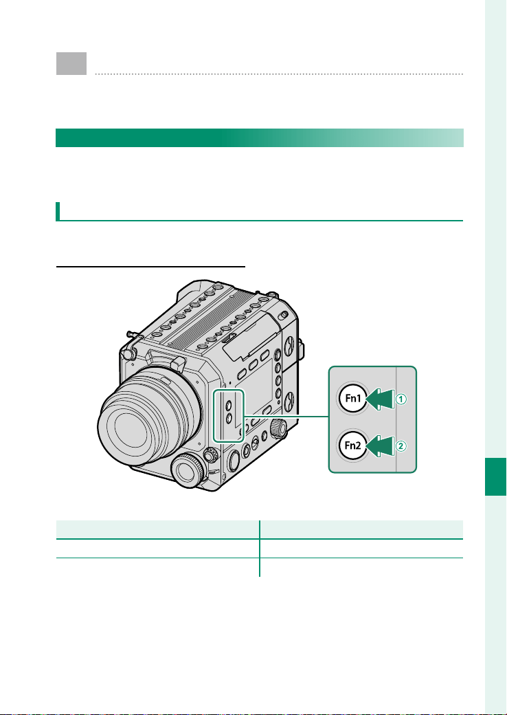
181
Shortcuts
8
Function Controls
Assign a role to each function button for quick access to
the selected feature.
The Function Buttons
Assign a role to the function buttons for quick access to the se-
lected feature.
Function Button Defaults
The default assignments are:
Function Buttons Inside the Camera
Function Buttons Inside the Camera
Function buttons
Function buttons
Default
Default
A
Fn1 button
ND ON/CLEAR
ND ON/CLEAR
B
Fn2 button
SDI/HDMI OUTPUT DISP
SDI/HDMI OUTPUT DISP
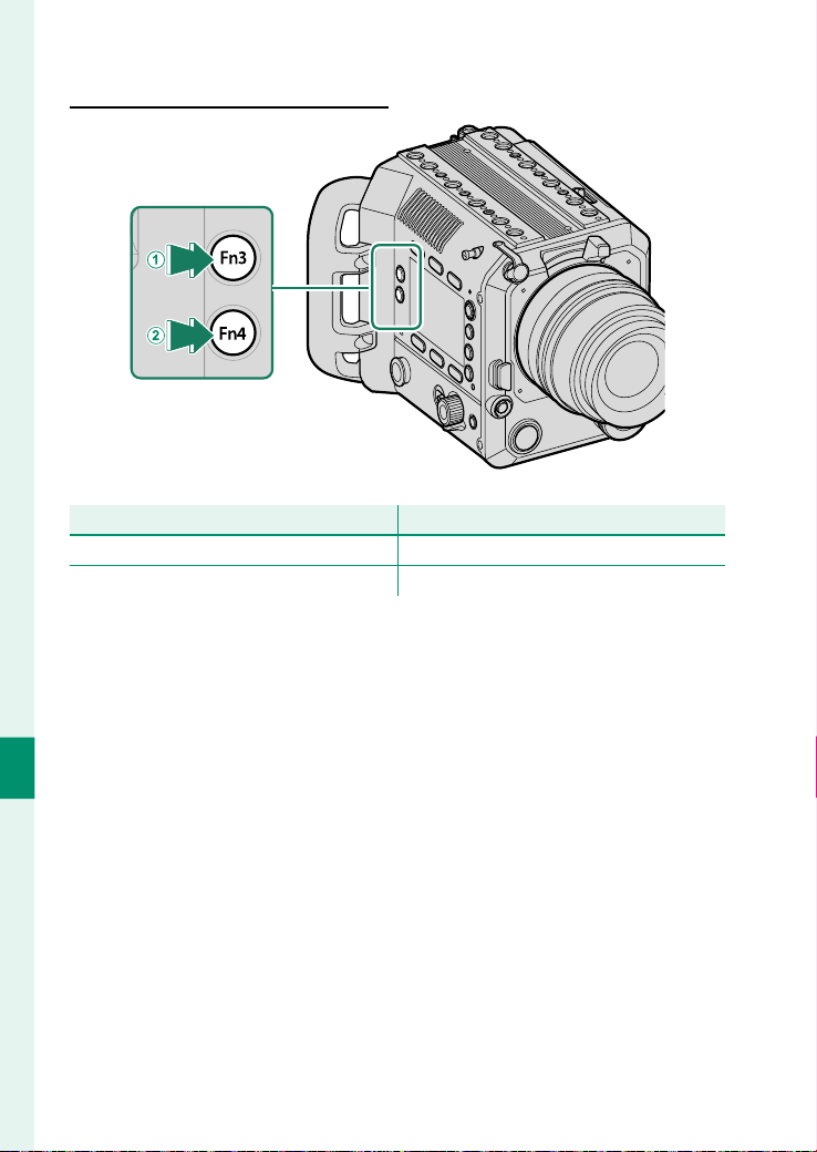
182
Shortcuts
8
Function Buttons Outside the Camera
Function Buttons Outside the Camera
Function buttons
Function buttons
Default
Default
A
Fn3 button
ND ON/CLEAR
ND ON/CLEAR
B
Fn4 button
SDI/HDMI OUTPUT DISP
SDI/HDMI OUTPUT DISP
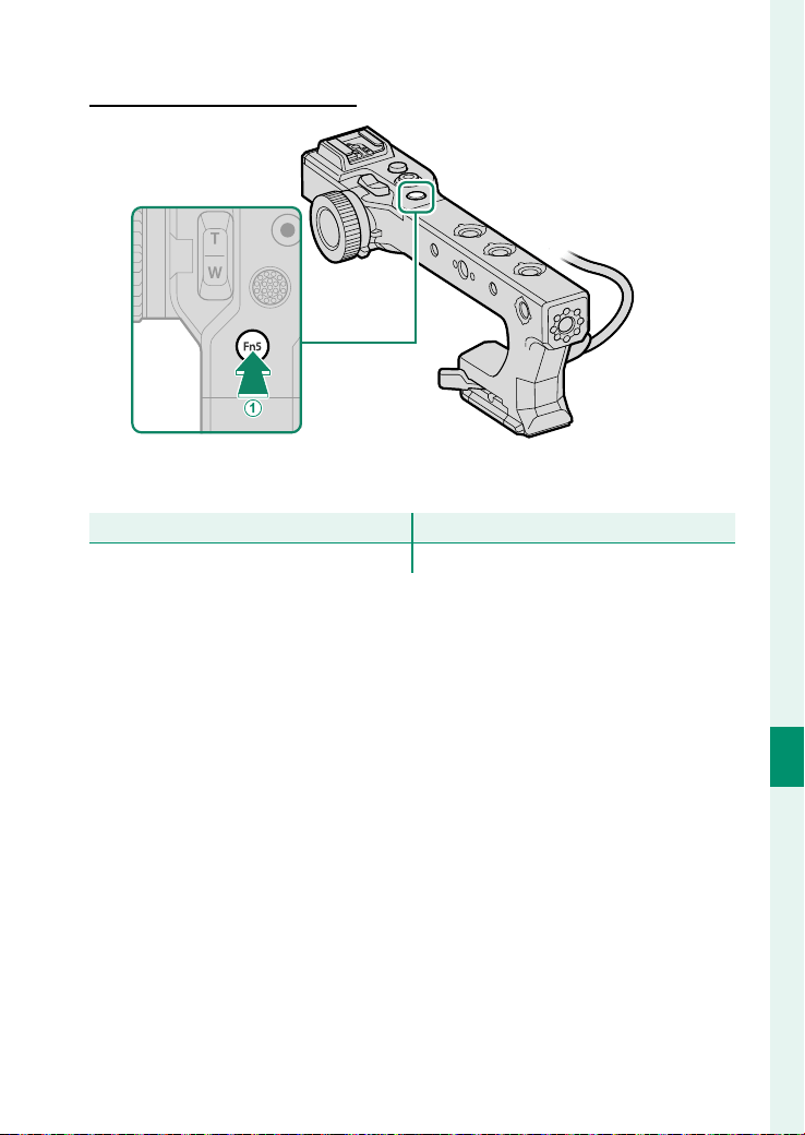
183
Shortcuts
8
Function Controls
Function Buttons on the Handle
Function Buttons on the Handle
Function buttons
Function buttons
Default
Default
A
Fn5 button
AF-ON
AF-ON
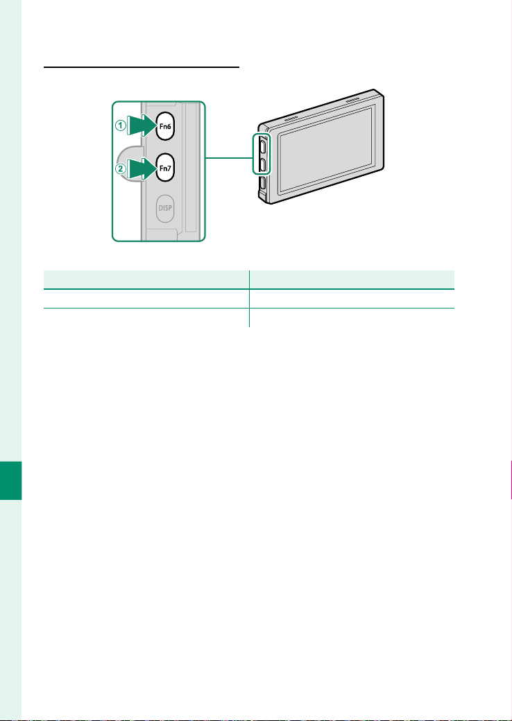
184
Shortcuts
8
Function Buttons on the LCD Monitor
Function Buttons on the LCD Monitor
Function buttons
Function buttons
Default
Default
A
Fn6 button
WAVEFORM/VECTORSCOPE
WAVEFORM/VECTORSCOPE
B
Fn7 button
FOCUS PEAK HIGHLIGHT
FOCUS PEAK HIGHLIGHT

185
Shortcuts
8
Function Controls
Assigning Roles to the Function Buttons
The roles played by the function buttons can be selected using
the USER > Fn SETTING options. The roles to be assigned are as
follows:
•
ND ON/CLEAR
•
LOOK SETTING A/C
•
AWB LOCK SWITCH
•
AWB LOCK PRESS
•
IRIS +
•
IRIS -(OPEN)
•
IRIS AUTO
•
EXPO.COMP +1/4
•
EXPO.COMP -1/4
•
PHOTOMETRY
•
IS MODE
•
IS MODE BOOST
•
SELF-TIMER
•
FOCUS AREA
•
FOCUS CHECK LOW
•
FOCUS CHECK HIGH
•
FOCUS CHECK LOW/HIGH
•
AF MODE
•
SUBJECT DETECTION SETTING
•
AF RANGE LIMITER
•
FOCUS CHECK LOCK
•
AF LOCK SWITCH
•
PRESS
•
AF-ON
•
INTERNAL/EXTERNAL MIC LEVEL
ADJUSTMENT
•
4ch AUDIO PLAYBACK
•
SDI/HDMI OUTPUT DISP
•
WAVEFORM/VECTORSCOPE
•
FOCUS PEAK HIGHLIGHT
•
ZEBRA SETTING
•
FRAMING GUIDELINE
•
ELECTRONIC LEVEL SWITCH
•
LCD INVERSION
•
CONSTANT SPEED ZOOM (T)
•
CONSTANT SPEED ZOOM (W)
•
F CONSTANT SPEED FOCUS (N)
•
F CONSTANT SPEED FOCUS (F)
•
Bluetooth ON/OFF
•
COOLING FAN SETTING
•
LCD BRIGHTNESS
•
PLAYBACK
•
NONE
N
To disable the function button, choose NONE .

186
Shortcuts
8
Function Controls
AF Lock Using Function Buttons
Use the function button to lock focus (AF lock) or adjust the focus
during autofocus shooting.
•
Press the function button to which AF LOCK SWITCH is as-
signed to lock the focus. Press the button again to release the
focus lock.
•
Press the function button to which PRESS is assigned to lock
the focus while the button is pressed. Release the button to re-
lease the focus lock.
•
Press the function button to which AF-ON is assigned to adjust
the focus again.
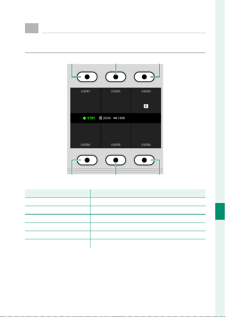
187
Shortcuts
8
USER Function
Set the screen button functions when the USER button is
pressed in shooting mode.
Screen button 1 Screen button 2 Screen button 3
GF 4K 16:9
±0.0 1.5dB
IMAGE FORMAT
RESOLUTION/ASPECT RATIO
FILM SIMULATION
A
UTO1
EXP. COMPENSATION
MANUAL ADJUSTMENT
INTERNAL MIC LEVEL
COOLING FAN SETTING
PRESS DIAL:CUSTOM
Screen button 4 Screen button 5 Screen button 6
Screen buttons
Screen buttons
Default
Default
Screen button 1
IMAGE FORMAT
IMAGE FORMAT
Screen button 2
RESOLUTION/ASPECT
RESOLUTION/ASPECT
Screen button 3
FILM SIMULATION
FILM SIMULATION
Screen button 4
EXP. COMPENSATION
EXP. COMPENSATION
Screen button 5
INT/EXT MIC LEVEL MANUAL ADJUSTMENT
INT/EXT MIC LEVEL MANUAL ADJUSTMENT
Screen button 6
COOLING FAN SETTING
COOLING FAN SETTING

188
Shortcuts
8
Function Controls
Assigning Roles to the Screen Buttons
Press the center of the selector dial on the USER display to change
the functions assigned to each screen button. The functions to
be assigned are as follows:
•
IMAGE FORMAT
•
RESOLUTION/ASPECT
•
PROJECT FPS
•
BITRATE
•
FILM SIMULATION
•
IRIS
•
EXP. COMPENSATION
•
PHOTOMETRY
•
SELF-TIMER
•
IS MODE
•
IS MODE BOOST
•
TONE CURVE
•
COLOR
•
SHARPNESS
•
NOISE REDUCTION
•
SUBJECT DETECTION SETTING
•
TOUCH SCREEN MODE
•
INT/EXT MIC LEVEL ADJUSTMENT
•
INT/EXT MIC LEVEL MANUAL ADJUSTMENT
•
WAVEFORM/VECTORSCOPE
•
FOCUS PEAK HIGHLIGHT
•
COOLING FAN SETTING
•
LCD BRIGHTNESS
•
LCD COLOR
•
NON
N
To disable the screen button, choose NON .

189
Peripherals and Optional
Accessories
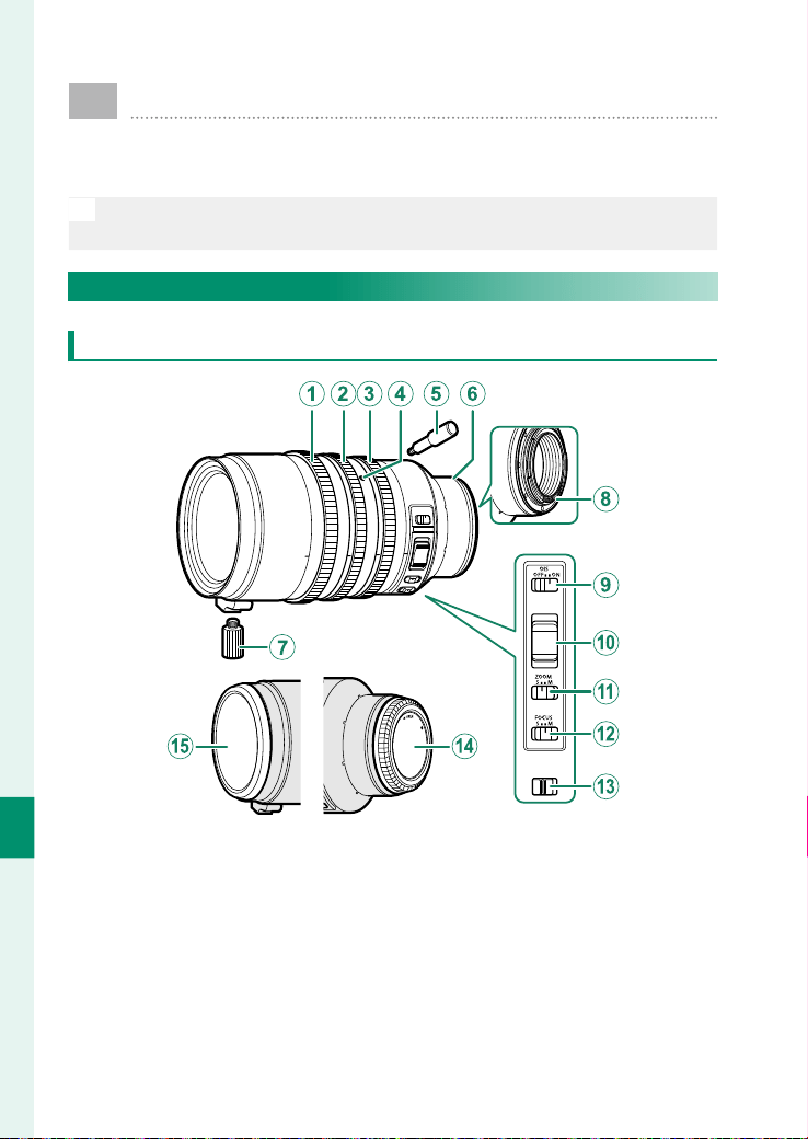
190
Peripherals and Optional Accessories
9
Lenses
The camera can be used with lenses for the FUJIFILM
G-mount.
N
See the manual provided with the lens for information on how to use
lenses.
Lens Parts
GF32-90mmT3.5 PZ OIS WR
A
Focus ring
B
Zoom ring
C
Aperture (iris) ring
D
Zoom lever socket hole
E
Zoom lever
F
Mounting marks
G
Support foot
H
Lens signal contacts
I
O.I.S. switch
J
Zoom lever
K
Zoom mode switch
L
Focus mode switch
M
Aperture (iris) ring lock switch
N
Rear lens cap
O
Front lens cap
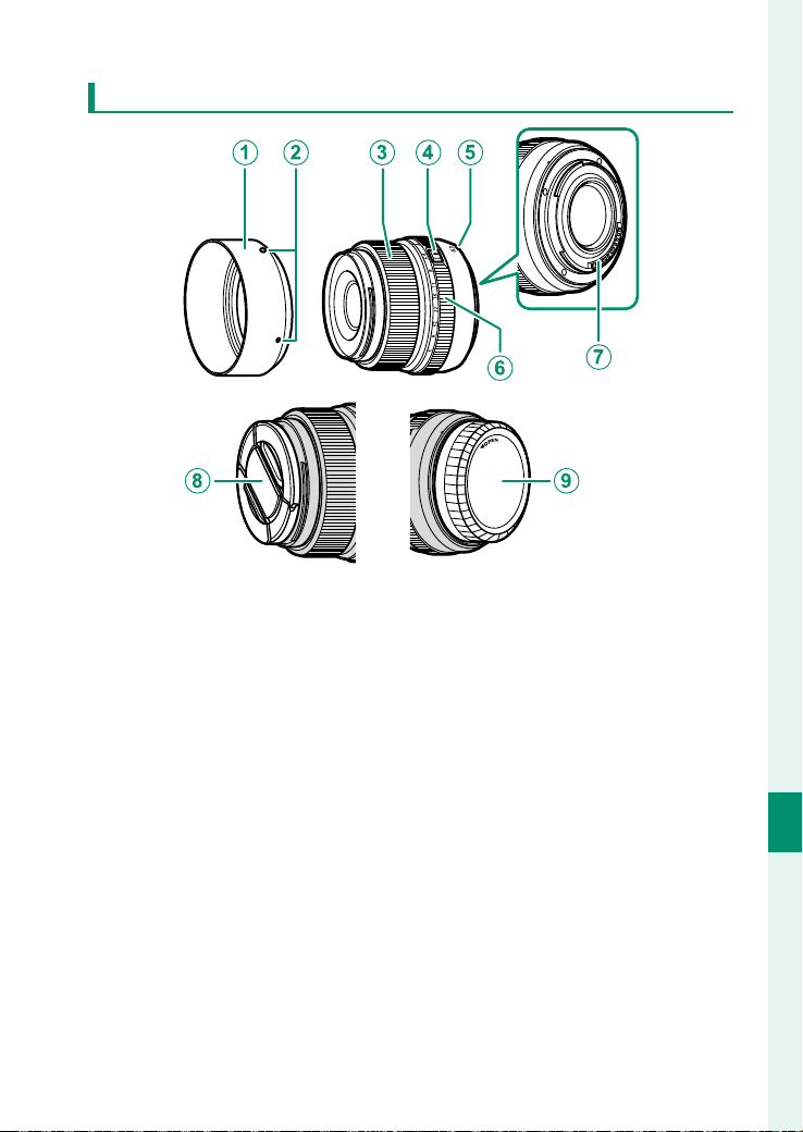
191
Peripherals and Optional Accessories
9
Lenses
GF63mmF2.8 R WR
A
Lens hood
B
Mounting marks
C
Focus ring
D
Aperture ring lock release
E
Mounting marks (focal length)
F
Aperture ring
G
Lens signal contacts
H
Front lens cap
I
Rear lens cap
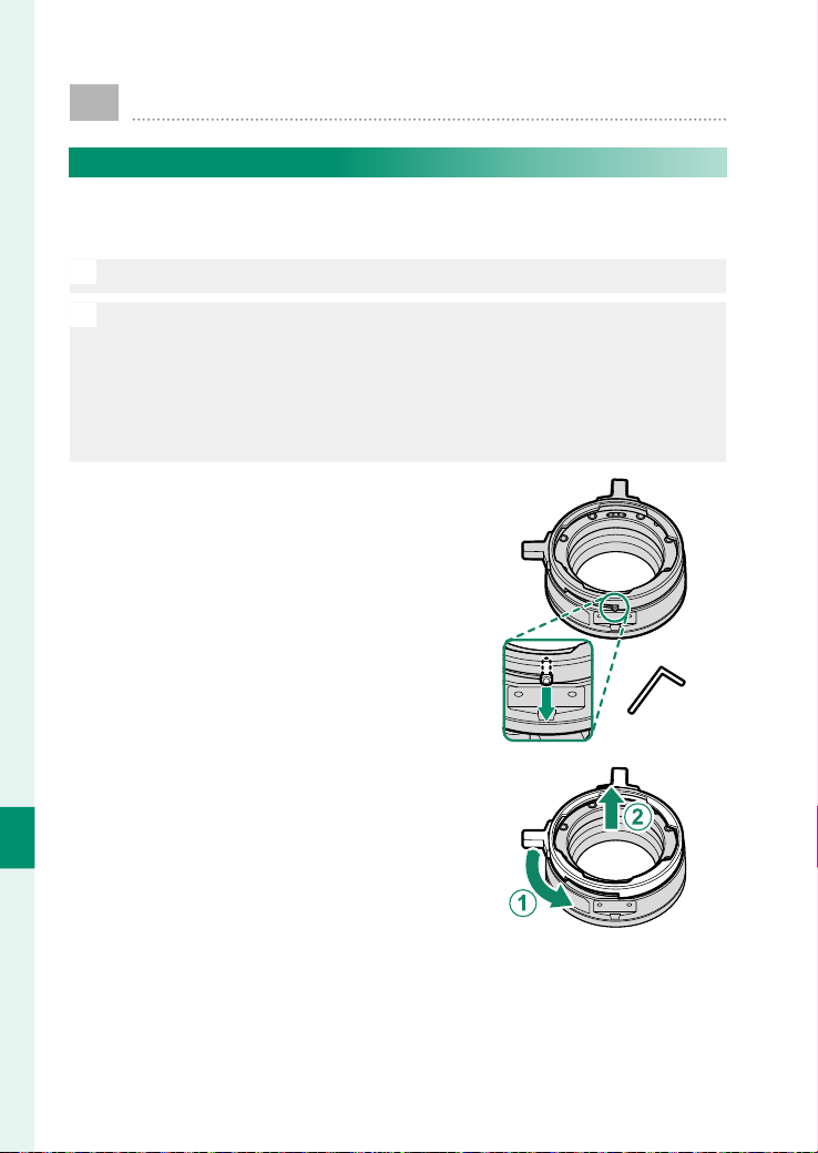
192
Peripherals and Optional Accessories
9
PL-Mount Adapter
Replacing the Shim on the PL-Mount Adapter
Replace the shim with one that is appropriate for the lens you
use.
O
Do not touch the shims with your hands.
N
•
Shims of the following thicknesses are supplied:
-
0.01mm/0.025mm/0.038mm/0.05mm/0.075mm/0.125mm
-
The PL-mount adapter comes with a 0.1mm thick shim built in at
the factory.
•
Hex wrenches with the following dimensions are supplied:
-
1.5mm/2mm/3mm
1
Remove the bayonet ring.
Use the supplied hex wrench (1.5mm)
to remove the stopper screw.
2
Rotate the bayonet ring counter-
clockwise (
A
) and remove it (
B
).
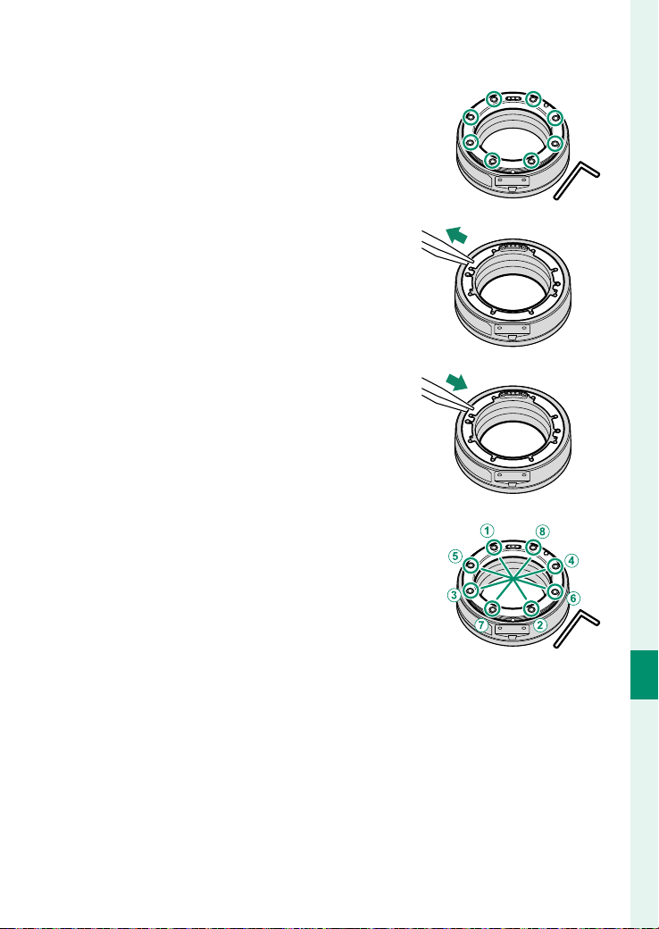
193
Peripherals and Optional Accessories
9
PL-Mount Adapter
3
Use the supplied hex wrench (2mm)
to remove eight screws.
4
Remove the lens mount and remove
the shim with tweezers.
5
Select the shim appropriate for the
lens you are using and attach it with
tweezers.
Attach the shims in order of thick-
ness, starting with the thinnest shim
and ending with the thickest shim.
6
Attach the lens mount.
Use the supplied hex wrench (2mm)
to install the eight screws diagonal-
ly in the order shown in the gure.
Lightly tighten the eight screws.
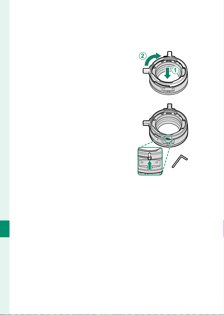
194
Peripherals and Optional Accessories
9
7
Retighten the eight screws in the order as in Step 6.
Use the supplied hex wrench (2mm) to tighten the screws.
When using a torque wrench, set the torque to 0.36N·m.
8
Attach the bayonet ring to the
PL-mount adapter (
A
) and rotate it
clockwise until it stops (
B
).
9
Rotate it counterclockwise about
halfway until the stopper screw hole
is visible and use the supplied hex
wrench (1.5mm) to attach the stop-
per screw.
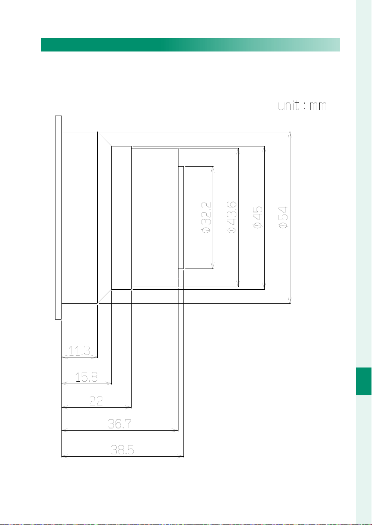
195
Peripherals and Optional Accessories
9
PL-Mount Adapter
Maximum Dimensions of PL-mount Lenses
When using PL-mount lenses, use only lenses that do not exceed
the following dimensions to avoid injury and damage to the
camera and lenses.

196
Peripherals and Optional Accessories
9
Connecting to External Devices
Connect external devices to the camera body connectors.
N
Output is only provided to the 12-pin connector for lens connection,
SDI OUT connector, HDMI OUT connector, and DC OUT 12 V connector
when the camera is powered by the AC power adapter or V-mount
battery. No output is provided when the camera is powered by the
supplied battery.
12-pin Connector for Lens Connection
Connect to a lens with a 12-pin lens connector to supply power
to the lens servo.
SDI OUT Connector (BNC Type)
Output footage when ON is selected for SDI/HDMI OUTPUT
SETTING > SDI OUTPUT SETTING in MONITOR SETTING . Use
SDI/HDMI OUTPUT SETTING to con gure the resolution and en-
able or disable the screen display and control signal.
HDMI OUT Connector (Type A)
Output footage when ON is selected for SDI/HDMI OUTPUT
SETTING > HDMI OUTPUT in MONITOR SETTING . Use SDI/HDMI
OUTPUT SETTING to con gure the resolution and enable or dis-
able the screen display and control signal.
TC IN/TC OUT Connector (BNC Type)
Input the time code synchronization signal from external devices
or output the synchronization signal. Use TIME CODE SETTING >
TIME CODE CONNECTOR to switch the settings.

197
Peripherals and Optional Accessories
9
Connecting to External Devices
LAN Connector
A connector for connecting a LAN cable (P 102).
Genlock Connector (BNC Type)
Synchronize the phase of the footage with external devices when
ON is selected for RECORDING > GENLOCK .
DC OUT 12 V Connector
When the camera is turned on, it outputs
12 V DC power. The connector shape and
connector pin layout are as shown in the
gure.
A
Ground
B
12 V
12
Figure:
Front of connector
O
•
The rated output is 12 V, 3 A. Output will stop if the rated output is
exceeded.
•
FGG.0B.302.CLAD35Z can be connected.
•
Turn the camera o before connecting or disconnecting devices. Do-
ing so while the power is on could cause the camera to stop func-
tioning.
•
Do not short the pins with each other or with the camera exterior, or
apply voltage to them. Failure to observe this precaution could dam-
age the camera.
N
•
Connecting a device to the DC OUT 12 V connector will cause the
V-mount battery to drain more quickly.
•
When using the DC OUT 12 V connector, we recommend that you
use the AC power adapter or the V-mount battery with a rated output
of 10 A or higher.

198
Peripherals and Optional Accessories
9
V-mount Batteries
Using an optional V-mount battery allows you to supply
power to the camera instead of using an AC power adapter,
or charge the supplied battery.
N
Recording while charging the supplied battery with a V-mount battery
will cause the V-mount battery to drain more quickly.
Compatible V-mount Batteries
This camera can use V-mount batteries with the following speci-
cations:
•
Input voltage range: 11.0 to 17.0 V
O
Depending on the dimensions of the V-mount battery, it may interfere
with cables attached to the camera. Make sure there is no interference
before using it.
N
When using the DC OUT 12 V connector, we recommend that you use
the V-mount battery with a rated output of 10 A or higher or the AC
power adapter.

199
Peripherals and Optional Accessories
9
V-mount Batteries
Attaching the V-mount Battery
Insert the V-mount battery into the V-mount battery attachment
mount from above. Slide it down until the V-mount battery re-
lease button appears.
Removing the V-mount Battery
Slide the V-mount battery upward while pressing the V-mount battery release
button to remove it.
O
•
If the AC power adapter or V-mount battery is removed while the
camera is powered on and the supplied battery is in the camera, the
screen display and terminal output will be turned o , and no opera-
tion other than turning o the camera can be performed. Attaching
the AC power adapter or V-mount battery again will restore normal
operation. If the AC power adapter or V-mount battery is removed
during movie recording, the recording will stop immediately.
•
If the supplied battery is low or the camera is used in a low-temper-
ature environment, removing the V-mount battery could cause the
camera to stop functioning, even if the supplied battery is in the
camera.
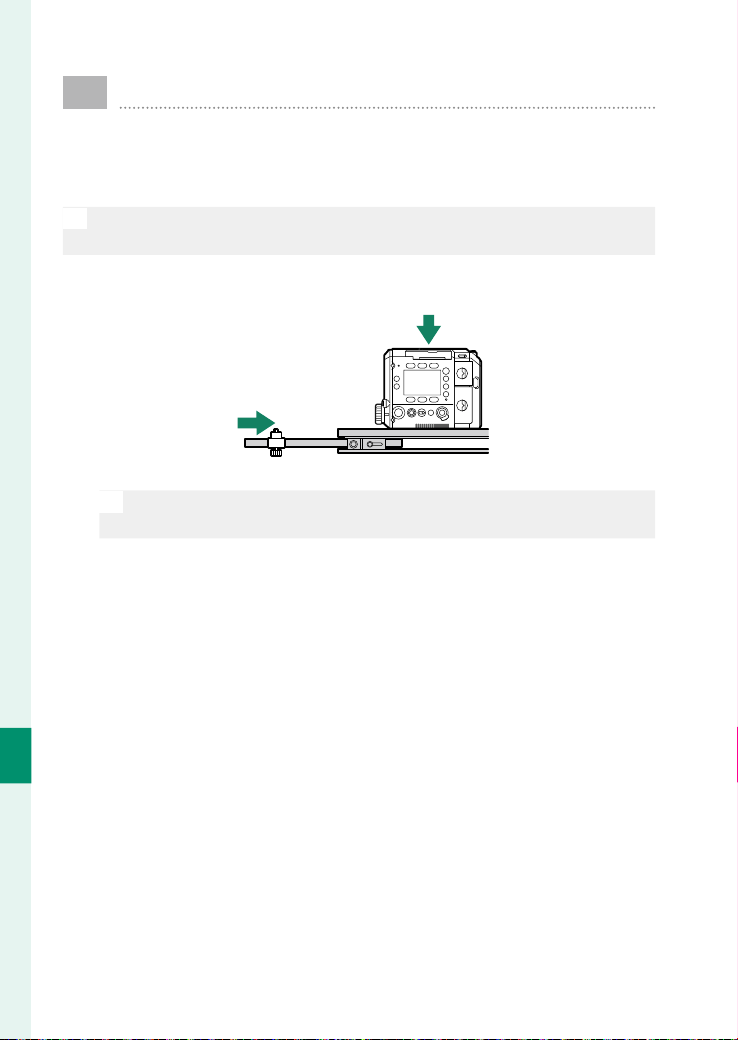
200
Peripherals and Optional Accessories
9
Attaching the Camera to the Support Rod
To protect the mount of camera, lens, and PL-mount adapt-
er, use a commercially available bridge plate and lens sup-
port.
O
Be sure to attach them securely. The camera or lens may fall. Dropping
from a high place, in particular, can lead to serious accidents.
1
Attach the camera and lens support to the bridge plate.
O
For installation instructions, refer to the instruction manuals for the
bridge plate and lens support.
2
Attach the lens and PL-mount adapter to the camera-mount
(P 47).
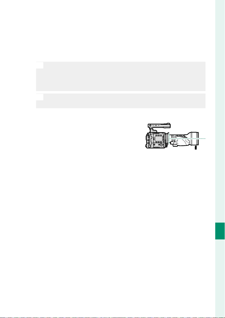
201
Peripherals and Optional Accessories
9
Attaching the Camera to the Support Rod
3
Support the lens with your hand and adjust the height and
position of the lens support so that the lens is level when
viewed from the side, then secure the lens support to the
support frame of the lens or PL-mount adapter cover.
O
Adjust the height and position of the lens support carefully to
avoid placing excessive force on the camera, lens, or PL-mount
adapter mount. Improper adjustment may damage the camera,
lens, or PL-mount adapter mount.
N
The support frame of the PL-mount adapter cover can also be at-
tached to the PL-mount adapter for use (P 51).
4
Check that the lens is level when
viewed from the side.

202
MEMO

203
Technical Notes

204
Technical Notes
10
Accessories from Fuji lm
The following accessories are available from Fuji lm. For
the latest information on the accessories available in your
region, check with your local Fuji lm representative or visit
https://fujifilm-x.com/support/compatibility/cameras/.
Rechargeable Li-ion batteries
Rechargeable Li-ion batteries
NP-W235: Additional high-capacity NP-W235 rechargeable batteries can be pur-
chased as required.
Dual battery chargers
Dual battery chargers
BC-W235: The BC-W235 can charge up to two NP-W235 batteries at a time. At
+25°C/+77°F, the batteries will charge in about 200minutes. Using a device that
supplies power with an outputs of 30W or above reduces charging times to as
little as 150minutes.
FUJINON lenses
FUJINON lenses
GF-series lenses: Interchangeable lenses for use exclusively with the FUJIFILM
G-mount.
Mount adapters
Mount adapters
H MOUNT ADAPTER G: This mount adapter allows the camera to be used with
SUPEREBC FUJINON accessories for the GX645AF, giving you the use of one ad-
ditional teleconverter and nine diff erent lenses.
Macro extension tubes
Macro extension tubes
MCEX-18G WR/MCEX-45G WR: Mount this adapter between the lens and the camera
body for macro photography with large reproduction ratios.
View camera adapters
View camera adapters
VIEW CAMERA ADAPTER G: This adapter is for use with lenses for older FUJINON
large-format cameras, including lenses in the CM FUJINON series.

205
Technical Notes
10
Accessories from Fuji lm
Remote releases
Remote releases
RR-100: Use to reduce camera shake or keep the shutter open during a time expo-
sure. The RR-100 has a connector with a diameter of 2.5 mm.
Body caps
Body caps
BCP-002: Cover the camera lens mount when no lens is attached.

206
Technical Notes
10
Software and Services for Use with Your
Camera
The camera can be used with the following software and
services. For the latest information on software available
from Fuji lm, visit
https://fujifilm-x.com/support/compatibility/cameras/.
Frame.io Camera to Cloud
Send still images and movies directly from the camera to the
Frame.io platform via a network.
https://frame.io/
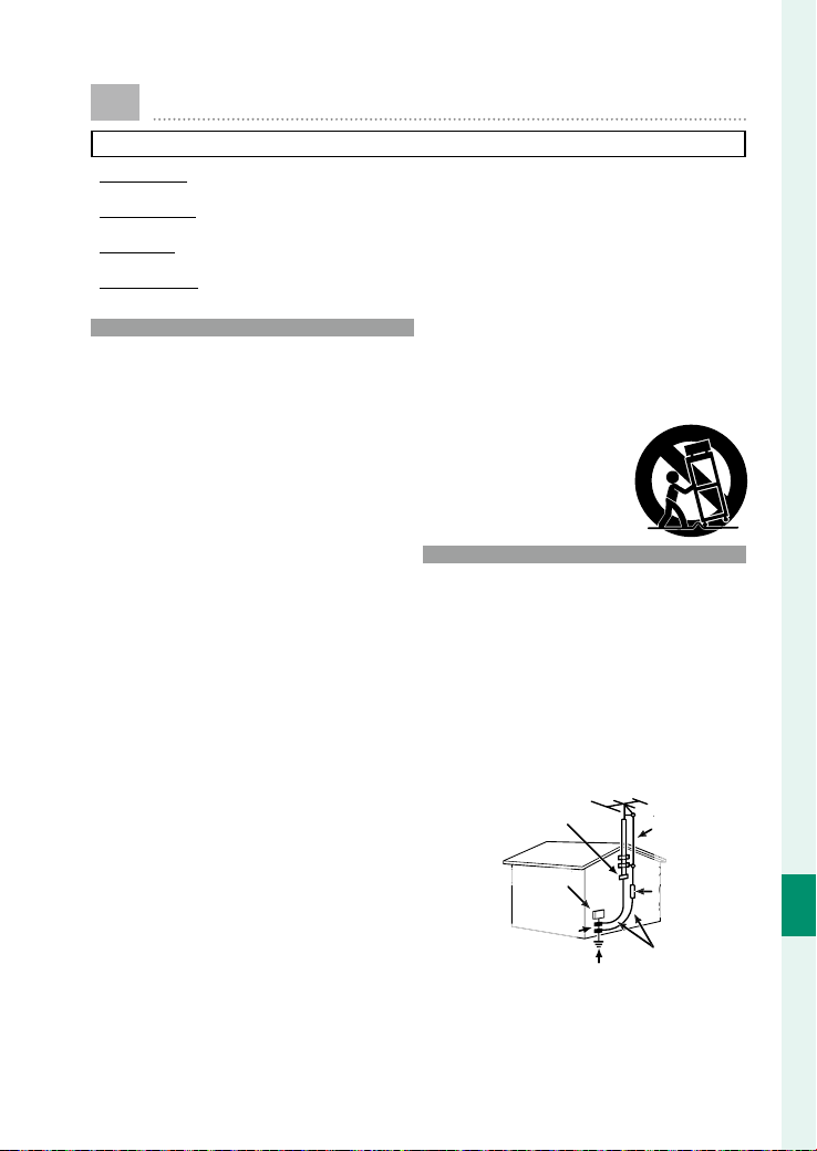
207
Technical Notes
10
For Your Safety
IMPORTANT SAFETY INSTRUCTIONS
•
Read Instructions
Read Instructions: All the safety and operating instructions
should be read before the appliance is operated.
•
Retain Instructions
Retain Instructions: The safety and operating instructions
should be retained for future reference.
•
Heed Warnings
Heed Warnings: All warnings on the appliance and in the
operating instructions should be adhered to.
•
Follow Instructions
Follow Instructions: All operating and use instructions
should be followed.
Installation
Installation
Power Sources: This video product should be operated only
from the type of power source indicated on the marking la-
bel. If you are not sure of the type of power supply to your
home, consult your appliance dealer or local power com-
pany. For video products intended to operate from battery
power, or other sources, refer to the operating instructions.
Grounding or Polarization: This video product is equipped
with a polarized alternating-current line plug (a plug having
one blade wider than the other). This plug will fi t into the
power outlet only one way. This is a safety feature. If you are
unable to insert the plug fully into the outlet, try reversing
the plug. If the plug should still fail to fi t, contact your electri-
cian to replace your obsolete outlet. Do not defeat the safety
purpose of the polarized plug.
Alternate Warnings: This video product is equipped with
a three-wire grounding-type plug, a plug having a third
(grounding) pin. This plug will only fi t into a grounding-type
power outlet. This is a safety feature. If you are unable to
insert the plug into the outlet, contact your electrician to re-
place your obsolete outlet. Do not defeat the safety purpose
of the grounding type plug.
Overloading: Do not overload wall outlets and extension
cords as this can result in a risk of fi re or electric shock.
Ventilation: Slots and openings in the cabinet are provided
for ventilation, to ensure reliable operation of the video prod-
uct and to protect it from overheating, and these openings
must not be blocked or covered. The openings should never
be blocked by placing the video product on a bed, sofa, rug,
or other similar surface.
This video product should not be placed in a built-in instal-
lation such as a bookcase or rack unless proper ventilation is
provided or the manufacturer’s instructions have been ad-
hered to. This video product should never be placed near or
over a radiator or heat register.
Attachments: Do not use attachments not recommended by
the video product manufacturer as they may cause hazards.
Water and Moisture: Do not use this video product near wa-
ter—for example, near a bath tub, wash bowl, kitchen sink,
or laundry tub, in a wet basement, or near a swimming pool,
and the like.
Power-Cord Protection: Power-supply cords should be routed
so that they are not likely to be walked on or pinched by
items placed upon or against them, paying particular atten-
tion to cords at plugs, convenience receptacles, and the point
where they exit from the appliance.
Accessories: Do not place this video product on an unstable
cart, stand, tripod, bracket, or table. The video product may
fall, causing serious injury to a child or adult, and serious
damage to the appliance. Use only with a cart, stand, tripod,
bracket, or table recommended by the manufacturer, or sold
with the video product. Any mounting of the appliance
should follow the manufacturer’s instructions, and should
use a mounting accessory recommended by the manufac-
turer.
An appliance and cart combination
should be moved with care. Quick
stops, excessive force, and uneven
surfaces may cause the appliance and
cart combination to overturn.
Antennas
Antennas
Outdoor Antenna Grounding: If an outside antenna or cable
system is connected to the video product, be sure the an-
tenna or cable system is grounded so as to provide some
protection against voltage surges and built-up static charges.
Section 810 of the National Electrical Code, ANSI/NFPA No.
70, provides information with respect to proper grounding of
the mast and supporting structure, grounding of the lead-in
wire to an antenna discharge unit, size of grounding con-
ductors, location of antenna discharge unit, connection to
grounding electrodes, and requirements for the grounding
electrode.
EXAMPLE OF ANTENNA GROUNDING AS
PER NATIONAL ELECTRICAL CODE
Ground Clamp
t
Electric Service Equipment
e Equipment
A
A
ntenn
a
Le
ad
in
W
ir
e
A
A
Antenna
An
Discharge Unit
D
(NEC SECTION
N
810-20)
8
Ground Clamps
Power Service Grounding Electrode
System (NEC ART 250. PART H)
Groun
d
in
g
Conductors
(
NEC
SECTION 810-21
)
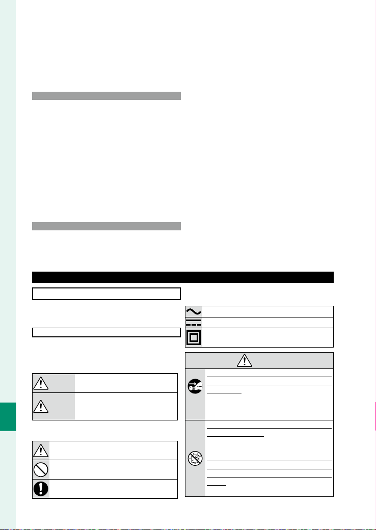
208
Technical Notes
10
Power Lines: An outside antenna system should not be locat-
ed in the vicinity of overhead power lines or other electric
light or power circuits, or where it can fall into such power
lines or circuits. When installing an outside antenna system,
extreme care should be taken to keep from touching such
power lines or circuits as contact with them might be fatal.
Use
Use
Cleaning: Unplug this video product from the wall outlet be-
fore cleaning. Do not use liquid cleaners or aerosol cleaners.
Use a damp cloth for cleaning.
Object and Liquid Entry: Never push objects of any kind into
this video product through openings as they may touch dan-
gerous voltage points or short out parts that could result in
a fi re or electric shock. Never spill liquid of any kind on the
video product.
Lightning: For added protection for this video product re-
ceiver during a lightning storm, or when it is left unattended
and unused for long periods of time, unplug it from the wall
outlet and disconnect the antenna or cable system. This will
prevent damage to the video product due to lightning and
power-line surges.
Service
Service
Servicing: Do not attempt to service this video product
yourself as opening or removing covers may expose you to
dangerous voltage or other hazards. Refer all servicing to
qualifi ed service personnel.
Damage Requiring Service: Unplug this video product from
the wall outlet and refer servicing to qualifi ed service person-
nel under the following conditions:
•
When the power-supply cord or plug is damaged
•
If liquid has been spilled, or objects have fallen into the
video product.
•
If the video product has been exposed to rain or water.
•
If the video product has been dropped or the cabinet has
been damaged.
If the video product does not operate normally follow the
operating instructions. Adjust only those controls that are
covered by the operating instructions as an improper adjust-
ment of other controls may result in damage and will often
require extensive work by a qualifi ed technician to restore
the video product to its normal operation.
When the video product exhibits a distinct change in perfor-
mance — this indicates a need for service.
Replacement Parts: When replacement parts are required, be
sure the service technician has used replacement parts spec-
ifi ed by the manufacturer or have the same characteristics as
the original part. Unauthorized substitutions may result in
fi re, electric shock or other hazards.
Safety Check: Upon completion of any service or repairs to
this video product, ask the service technician to perform
safety checks to determine that the video product is in prop-
er operating condition.
Be sure to read these notes before use
Safety Notes
•
Make sure that you use your camera correctly. Read these
safety notes and your Owner’s Manual carefully before use.
•
After reading these safety notes, store them in a safe place.
About the Icons
The icons shown below are used in this document to indicate
the severity of the injury or damage that can result if the in-
formation indicated by the icon is ignored and the product is
used incorrectly as a result.
WARNING
WARNING
This icon indicates that death or serious in-
jury can result if the information is ignored.
CAUTION
CAUTION
This icon indicates that personal injury or
material damage can result if the informa-
tion is ignored.
The icons shown below are used to indicate the nature of the
instructions which are to be observed.
Triangular icons tell you that this information re-
quires attention (“Important”).
Circular icons with a diagonal bar tell you that the
action indicated is prohibited (“Prohibited”).
Filled circles with an exclamation mark indicate an
action that must be performed (“Required”).
The symbols on the product (including the accessories) rep-
resent the following:
AC
DC
Class II equipment (The construction of the product
is double-insulated.)
WARNING
WARNING
Unplug
from power
socket
If a problem arises, turn the camera o , remove the
If a problem arises, turn the camera o , remove the
battery, disconnect the USB cable, and unplug the AC
battery, disconnect the USB cable, and unplug the AC
power adapter.
power adapter. Continued use of the camera when
it is emitting smoke, is emitting any unusual odor,
or is in any other abnormal state can cause a fi re or
electric shock. Contact your Fujifi lm dealer.
Do not allow water or foreign objects to enter the cam-
Do not allow water or foreign objects to enter the cam-
era or connecting cables.
era or connecting cables. Do not use the camera or
connecting cables following ingress of fresh or salt
water, milk, beverages, detergents, or other liquids.
Should liquid nd its way into the camera or connecting
Should liquid nd its way into the camera or connecting
cables, turn the camera o , remove the battery, discon-
cables, turn the camera o , remove the battery, discon-
nect the USB cable, and disconnect and unplug the AC
nect the USB cable, and disconnect and unplug the AC
adapter.
adapter. Continued use of the camera can cause a
fi re or electric shock. Contact your Fujifi lm dealer.
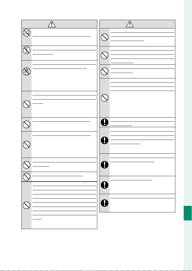
209
Technical Notes
10
For Your Safety
WARNING
WARNING
Do not use in
the bathroom
or shower
Do not use the camera in the bathroom or shower.
Do not use the camera in the bathroom or shower. This
can cause a fi re or electric shock.
Do not
disassemble
Never attempt to change or take apart the camera (nev-
Never attempt to change or take apart the camera (nev-
er open the case).
er open the case). Failure to observe this precaution
can cause fi re or electric shock.
Do not touch
internal
parts
Should the case break open as the result of a fall or
Should the case break open as the result of a fall or
other accident, do not touch the exposed parts.
other accident, do not touch the exposed parts. Failure
to observe this precaution could result in electric
shock or in injury from touching the damaged
parts. Remove the battery immediately, taking care
to avoid injury or electric shock, and contact your
Fujifi lm dealer.
Do not change, heat or unduly twist or pull the connec-
Do not change, heat or unduly twist or pull the connec-
tion cord and do not place heavy objects on the connec-
tion cord and do not place heavy objects on the connec-
tion cord.
tion cord. These actions could damage the cord and
cause a fi re or electric shock. If the cord is damaged,
contact your Fujifi lm dealer. Do not use cables with
bent connectors.
Do not place the camera on an unstable surface.
Do not place the camera on an unstable surface. This
can cause the camera to fall or tip over and cause
injury.
Never attempt to record movies while in motion.
Never attempt to record movies while in motion. Do
not use shooting, playback, or any other opera-
tions of the camera while operating a car or other
vehicle. This can result in you falling down or being
involved in a traffi c accident. If you record movies
while walking, pay attention to your surroundings.
Do not touch any metal parts of the camera during a
Do not touch any metal parts of the camera during a
thunderstorm.
thunderstorm. This can cause an electric shock due
to induced current from the lightning discharge.
Do not use the battery except as speci ed.
Do not use the battery except as speci ed. Load the
battery as shown by the indicator.
Do not disassemble, modify, or heat batteries. Do not
Do not disassemble, modify, or heat batteries. Do not
drop, strike, or throw batteries or otherwise subject
drop, strike, or throw batteries or otherwise subject
them to strong impacts. Do not use batteries that
them to strong impacts. Do not use batteries that
show signs of leaking, deformation, discoloration, or
show signs of leaking, deformation, discoloration, or
other abnormalities. Use only designated chargers to
other abnormalities. Use only designated chargers to
recharge rechargeable batteries and do not attempt to
recharge rechargeable batteries and do not attempt to
recharge non-rechargeable lithium or alkaline batter-
recharge non-rechargeable lithium or alkaline batter-
ies. Do not short batteries or store them with metallic
ies. Do not short batteries or store them with metallic
objects.
objects. Failure to observe these precautions could
result in the batteries overheating, igniting, ruptur-
ing, or leaking, causing fi re, burns, or other injury.
WARNING
WARNING
Use only batteries or AC power adapters speci ed for
Use only batteries or AC power adapters speci ed for
use with this camera. Do not use voltages other than the
use with this camera. Do not use voltages other than the
power supply voltage shown.
power supply voltage shown. The use of other power
sources can cause a fi re.
If the battery leaks and uid gets in contact with your
If the battery leaks and uid gets in contact with your
eyes, skin or clothing, ush the a ected area with clean
eyes, skin or clothing, ush the a ected area with clean
water and seek medical attention or call an emergency
water and seek medical attention or call an emergency
number right away.
number right away.
Using a ash too close to a person’s eyes may cause
Using a ash too close to a person’s eyes may cause
visual impairment.
visual impairment. Take particular care when pho-
tographing infants and young children.
Do not remain in prolonged contact with hot surfaces.
Do not remain in prolonged contact with hot surfaces.
Do not leave one part of the body in contact with the
Do not leave one part of the body in contact with the
product for prolonged periods while the product is on.
product for prolonged periods while the product is on.
Failure to observe this precaution could result in
low-temperature burns, particularly during pro-
longed use, at high ambient temperatures, or with
users who suff er from poor circulation or reduced
sensation, in which case use of a tripod or similar
precautions are recommended.
Do not use in the presence of ammable objects, explo-
Do not use in the presence of ammable objects, explo-
sive gases, or dust.
sive gases, or dust.
When carrying the battery, install it in a camera or keep
When carrying the battery, install it in a camera or keep
it in the hard case. When storing the battery, keep it in
it in the hard case. When storing the battery, keep it in
the hard case. When discarding, cover the battery termi-
the hard case. When discarding, cover the battery termi-
nals with insulation tape.
nals with insulation tape. Contact with other metal-
lic objects or batteries could cause the battery to
ignite or burst.
Keep memory cards, shoe covers, and other small parts
Keep memory cards, shoe covers, and other small parts
out of the reach of small children.
out of the reach of small children. Children may
swallow small parts; keep out of reach of children.
Should a child swallow a small part, seek medical
attention or call emergency.
Keep out of reach of small children.
Keep out of reach of small children. Among the ele-
ments that could cause injury are the strap, which
could become entangled about a child’s neck,
causing strangulation.
Follow the directions of airline and hospital personnel.
Follow the directions of airline and hospital personnel.
This product generates radio-frequency emissions
that could interfere with navigational or medical
equipment.
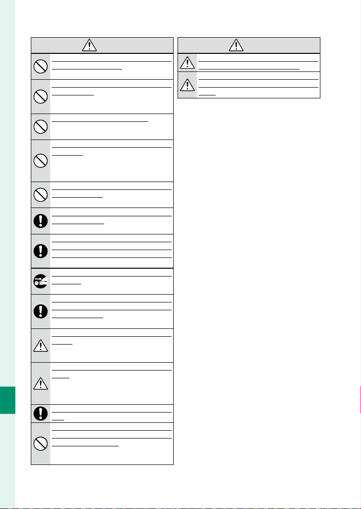
210
Technical Notes
10
CAUTION
CAUTION
Do not use this camera in locations a ected by oil
Do not use this camera in locations a ected by oil
fumes, steam, humidity or dust.
fumes, steam, humidity or dust. This can cause a fi re
or electric shock.
Do not leave this camera in places subject to extremely
Do not leave this camera in places subject to extremely
high temperatures.
high temperatures. Do not leave the camera in loca-
tions such as a sealed vehicle or in direct sunlight.
This can cause a fi re.
Do not place heavy objects on the camera.
Do not place heavy objects on the camera. This can
cause the heavy object to tip over or fall and cause
injury.
Do not move the camera while the AC power adapter is
Do not move the camera while the AC power adapter is
still connected.
still connected. Do not pull on the connection cord to
disconnect the AC power adapter. This can damage
the power cord or cables and cause a fi re or electric
shock.
Do not cover or wrap the camera or the AC power adapt-
Do not cover or wrap the camera or the AC power adapt-
er in a cloth or blanket.
er in a cloth or blanket. This can cause heat to build
up and distort the casing or cause a fi re.
Do not use the plug if it is damaged or if it does not t
Do not use the plug if it is damaged or if it does not t
securely into the outlet.
securely into the outlet. Failure to observe this pre-
caution could result in fi re or electric shock.
When you are cleaning the camera or you do not plan to
When you are cleaning the camera or you do not plan to
use the camera for an extended period, remove the bat-
use the camera for an extended period, remove the bat-
tery and disconnect and unplug the AC power adapter.
tery and disconnect and unplug the AC power adapter.
Failure to do so can cause a fi re or electric shock.
When charging ends, unplug the charger from the
When charging ends, unplug the charger from the
power socket.
power socket. Leaving the charger plugged into the
power socket can cause a fi re.
When a memory card is removed, the card could come
When a memory card is removed, the card could come
out of the slot too quickly. Use your nger to hold it and
out of the slot too quickly. Use your nger to hold it and
gently release the card.
gently release the card. Injury could result to those
struck by the ejected card.
Do not handle the memory card immediately after
Do not handle the memory card immediately after
shooting.
shooting. The memory card may be hot, resulting
in burns. Wait for the card to cool before removing
it from the camera.
Request regular internal testing and cleaning for your
Request regular internal testing and cleaning for your
camera.
camera. Build-up of dust in your camera can cause
a fi re or electric shock. Contact your Fujifi lm dealer
to request internal cleaning every two years. Please
note that this service is not free of charge.
Dispose of the product in accord with location regula-
Dispose of the product in accord with location regula-
tions.
tions.
Do not cover the air intakes or exhaust vent with tape
Do not cover the air intakes or exhaust vent with tape
or other materials. Do not place any obstructions near
or other materials. Do not place any obstructions near
the air intakes or exhaust vent.
the air intakes or exhaust vent. Failure to observe this
precaution may reduce cooling performance or
cause a malfunction.
CAUTION
CAUTION
Danger of explosion if battery is incorrectly replaced.
Danger of explosion if battery is incorrectly replaced.
Replace only with the same or equivalent type.
Replace only with the same or equivalent type.
Batteries (battery pack or batteries installed) shall not
Batteries (battery pack or batteries installed) shall not
be exposed to excessive heat such as sunshine, re or
be exposed to excessive heat such as sunshine, re or
the like.
the like.

211
Technical Notes
10
For Your Safety
The Battery and Power Supply
Note: Check the type of battery used in your camera and read
the appropriate sections.
WARNING: Battery shall not be exposed to excessive heat
such as sunshine, fire or the like.
The following describes the proper use of batteries and how
to prolong their life. Incorrect use can shorten battery life or
cause leakage, overheating, fi re, or explosion.
Li-ion Batteries
Li-ion Batteries
Read this section if your camera uses a rechargeable Li-ion
battery.
The battery is not charged at shipment. Charge the battery
before use. Keep the battery in its case when not in use.
L
L
Notes on the Battery
Notes on the Battery
The battery gradually loses its charge when not in use.
Charge the battery one or two days before use.
Battery life can be extended by turning the camera off when
not in use.
Battery capacity decreases at low temperatures; a depleted
battery may not function when cold. Keep a fully charged
spare battery in a warm place and exchange as necessary,
or keep the battery in your pocket or other warm place and
insert it in the camera only when shooting. Do not place the
battery in direct contact with hand warmers or other heating
devices.
L
L
Charging the Battery
Charging the Battery
The battery can be charged using the camera and supplied
AC adapter or an optional BC-W235 dual battery charger.
Charging times will increase at ambient temperatures below
+10 °C (+50 °F) or above +35 °C (+95 °F). Do not attempt to
charge the battery at temperatures above +40 °C (+104 °F); at
temperatures below +5 °C (+41 °F), the battery will not charge.
Do not attempt to recharge a fully charged battery. The battery
does not however need to be fully discharged before charging.
The battery may be warm to the touch immediately after
charging or use. This is normal.
L
L
Battery Life
Battery Life
A noticeable decrease in the length of time the battery will
hold a charge indicates that it has reached the end of its ser-
vice life and should be replaced.
If the battery is left for long periods without charging, you
may fi nd that its quality degrades or that it no longer holds a
charge. Charge the battery regularly.
L
L
Storage
Storage
If the camera will not be used for an extended period, store
it at room temperature with the battery charged to approxi-
mately one half to ⁄ capacity.
If the camera will not be used for an extended period, re-
move the battery and store it in a dry place with an ambient
temperature of from +15 °C to +25 °C (+59 °F to +77 °F). Do
not store in locations exposed to extremes of temperature.
L
L
Cautions: Handling the Battery
Cautions: Handling the Battery
•
Do not transport or store with metal objects such as neck-
laces or hairpins.
•
Do not expose to fl ame or heat.
•
Do not disassemble or modify.
•
Do not expose to low atmospheric pressures.
•
Use with designated chargers only.
•
Dispose of used batteries promptly.
•
Do not drop or subject to strong physical shocks.
•
Do not expose to water.
•
Keep the terminals clean.
•
The battery and camera body may become warm to the
touch after extended use. This is normal.
L
Caution:
Disposal
Disposal
Dispose of used batteries in accord with local regulations.
Attention should be drawn to the environmental aspects of
battery disposal. Use the apparatus under moderate climate.
Do not mechanically crush or split batteries.
AC Power Adapters
AC Power Adapters
•
Be sure the cable is securely connected to the camera.
•
Turn the camera off before disconnecting the adapter. Dis-
connect the adapter by the plug, not the cable.
•
Do not disassemble.
•
Do not expose to high heat and humidity.
•
Do not subject to strong physical shocks.
•
The adapter may hum or become hot to the touch during
use. This is normal.
•
If the adapter causes radio interference, reorient or relocate
the receiving antenna.

212
Technical Notes
10
Using the Camera
Do not aim the camera at extremely bright light sources, in-
cluding artifi cial light sources or natural light sources such as
the sun in a cloudless sky. Failure to observe this precaution
could damage the camera image sensor or ND fi lter.
Take Test Shots
Take Test Shots
Before taking photographs on important occasions (such as
at weddings or before taking the camera on a trip), take a
test shot and view the results to ensure that the camera is
functioning normally. FUJIFILMCorporation cannot accept
liability for damages or lost profi ts incurred as a result of
product malfunction.
Notes on Copyright
Notes on Copyright
Unless intended solely for personal use, images recorded us-
ing your camera system cannot be used in ways that infringe
copyright laws without the consent of the owner. Note
that some restrictions apply to the photographing of stage
performances, entertainments, and exhibits, even when in-
tended purely for personal use. Users are also asked to note
that the transfer of memory cards containing images or data
protected under copyright laws is only permissible within
the restrictions imposed by those copyright laws.
Handling
Handling
To ensure that images are recorded correctly, do not subject
the camera to impact or physical shocks while images are
being recorded.
Liquid Crystal
Liquid Crystal
In the event that the display is damaged, care should be tak-
en to avoid contact with liquid crystal. Take the urgent action
indicated should any of the following situations arise:
•
If liquid crystal comes in contact with your skin, clean the
area with a cloth and then wash thoroughly with soap and
running water.
•
If liquid crystal enters your eyes, fl ush the aff ected eye with
clean water for at least 15 minutes and then seek medical
assistance.
•
If liquid crystal is swallowed, rinse your mouth thoroughly
with water. Drink large quantities of water and induce vom-
iting, then seek medical assistance.
Although the display is manufactured using extremely
high-precision technology, it may contain pixels that are
always lit or that do not light. This is not a malfunction, and
images recorded with the product are unaff ected.
Trademark Information
Trademark Information
Digital Split Image is a trademark or registered trademark of
FUJIFILM Corporation. Digital Micro Prism is a trademark or
registered trademark of FUJIFILM Corporation. The typefaces
included herein are solely developed by DynaComware
Taiwan Inc. Apple, iPhone, iPad, Mac, Mac OS X, OS X, macOS,
Lightning and Apple ProRes are registered trademarks of
Apple Inc. in the U.S.A. and other countries. Windows is a
registered trademark of Microsoft Corporation in the U.S.A.
and other countries. Android is a trademark or registered
trademark of Google LLC. Adobe, the Adobe logo, Camera
to Cloud, Frame.io, Lightroom and Photoshop are either
registered trademarks or trademarks of Adobe in the United
States and/or other countries.
Wi-Fi®, the Wi-Fi CERTIFIED
logo, and Wi-Fi Protected Setup® are registered trademarks of
the Wi-Fi Alliance®.
The Bluetooth® word mark and logos are
registered trademarks owned by the Bluetooth SIG, Inc., and
any use of such marks by Fujifi lm is under license. The SDHC
and SDXC logos are trademarks of SD-3C, LLC. CFexpress is
a trademark of the CFA (CompactFlash Association). The
HDMI logo is a trademark or registered trademark of HDMI
Licensing LLC. QR Code is a registered trademark of DENSO
WAVE INCORPORATED. USB Type-C® and USB-C® are regis-
tered trademarks of USB Implementers Forum. AirGlu™ is a
trademark or registered trademark of Atomos. All other trade
names mentioned in this manual are the trademarks or regis-
tered trademarks of their respective owners.
Electrical Interference
Electrical Interference
This camera may interfere with hospital or aviation equip-
ment. Consult with hospital or airline staff before using the
camera in a hospital or on an aircraft.
Color Television Systems
Color Television Systems
NTSC (National Television System Committee) is a color tele-
vision telecasting specifi cation adopted mainly in the U.S.A.,
Canada, and Japan. PAL (Phase Alternation by Line) is a color
television system adopted mainly in European countries and
China.

213
Technical Notes
10
For Your Safety
IMPORTANT NOTICE: Read Before Using the Software
Direct or indirect export, in whole or in part, of licensed software without the permission of the applicable governing bodies
is prohibited.
Lenses and Other Accessories
•
Read the manuals provided with the camera and lens when attaching the lens, and attach the lens correctly. We cannot
guarantee accidents or malfunctions caused by incorrect attachment.
•
For accessory mounting screw holes, use products with a screw length less than or equal to the hole depth indicated in
the external dimensions (P 241).
•
Fujifi lm will not be held liable for performance issues or damage caused by the use of third-party accessories.
NOTICES
To prevent fire or shock hazard, do not expose the unit to rain or moisture.
Please read the “Safety Notes” and make sure you understand them before using the camera.
Perchlorate Material—special handling may apply. See:
http://www.dtsc.ca.gov/hazardouswaste/perchlorate

214
Technical Notes
10
For Customers in the U. S. A.
For Customers in the U. S. A.
Tested To Comply With FCC Standards
Contains IC : 10293A-BM25EXT
Contains FCC ID : COF-BM25-EXT
FCC Statement: This device complies with Part 15 of the FCC
Rules. Operation is subject to the following two conditions:
(1) This device may not cause harmful interference, and
(2)this device must accept any interference received, includ-
ing interference that may cause undesired operation.
CAUTION: This equipment has been tested and found to com-
ply with the limits for a Class A digital device, pursuant to
part 15 of the FCC Rules. These limits are designed to provide
reasonable protection against harmful interference when the
equipment is operated in a commercial environment. This
equipment generates, uses, and can radiate radio frequency
energy and, if not installed and used in accordance with the
instruction manual, may cause harmful interference to radio
communications. Operation of this equipment in a residen-
tial area is likely to cause harmful interference in which case
the user will be required to correct the interference at his
own expense.
•
Reorient or relocate the receiving antenna.
•
Increase the separation between the equipment and re-
ceiver.
•
Connect the equipment into an outlet on a circuit diff erent
from that to which the receiver is connected.
•
Consult the dealer or an experienced radio/TV technician
for help.
FCC Caution: Any changes or modifi cations not expressly ap-
proved by the party responsible for compliance could void
the user’s authority to operate this equipment.
This transmitter must not be co-located or operating in con-
junction with any other antenna or transmitter.
Radiation Exposure Statement: This device meets the gov-
ernment’s requirements for exposure to radio waves. This
device is designed and manufactured not to exceed the
emission limits for exposure to radio frequency (RF) energy
set by the Federal Communications Commission of the U.S.
Government.
The exposure standard for wireless device employs a unit of
measurement known as the Specifi c Absorption Rate, or SAR.
The SAR limit set by the FCC is 1.6W/kg. Tests for SAR are
conducted using standard operating positions accepted by
the FCC with the device transmitting at its highest certifi ed
power level in all tested frequency bands.
Notes on the Grant: To comply with Part 15 of the FCC Rules,
this product must be used with a Fujifi lm-specifi ed fer-
rite-core A/V cable, USB cable, and DC supply cord.
A lithium ion battery that is recyclable powers
the product you have purchased. Please call
1-800-8-BATTERY for information on how to
recycle this battery.
California Code of Regulations, Title 20, Di-
vision 2, Chapter4, Article4, Appliance Ef-
fi ciency Regulations, Sections 1601 through
1609
215
Technical Notes
10
For Your Safety
For Customers in Canada
For Customers in Canada
CAN ICES (A)/NMB (A)
CAUTION: This Class A digital apparatus complies with Cana-
dian ICES-003.
Industry Canada statement: This device complies with Indus-
try Canada’s licence-exempt RSSs. Operation is subject to the
following two conditions: (1)This device may not cause in-
terference; and (2)This device must accept any interference,
including interference that may cause undesired operation
of the device.
This device and its antenna(s) must not be co-located or op-
erating in conjunction with any other antenna or transmitter,
except tested built-in radios. The County Code Selection
feature is disabled for products marketed in the US/ Canada.
Radiation Exposure Statement: The available scientifi c evi-
dence does not show that any health problems are associat-
ed with using low power wireless devices. There is no proof,
however, that these low power wireless devices are absolute-
ly safe. Low power Wireless devices emit low levels of radio
frequency energy (RF) in the microwave range while being
used. Whereas high levels of RF can produce health eff ects
(by heating tissue), exposure of low-level RF that does not
produce heating eff ects causes no known adverse health ef-
fects. Many studies of low-level RF exposures have not found
any biological eff ects. Some studies have suggested that
some biological eff ects might occur, but such fi ndings have
not been confi rmed by additional research. The camera has
been tested and found to comply with IC radiation exposure
limits set forth for an uncontrolled environment and meets
RSS-102 of the IC radio frequency (RF) Exposure rules.
Operation in the band 5150–5250 MHz is only for indoor use
to reduce the potential for harmful interference to co-chan-
nel mobile satellite systems.
Disposal of Electrical and Electronic Equipment in Private Households
Disposal of Electrical and Electronic Equipment in Private Households
In the European Union, Norway, Iceland and
Liechtenstein: This symbol on the product, or in
the manual and in the warranty, and/or on its
packaging indicates that this product shall not
be treated as household waste. Instead it should
be taken to an applicable collection point for the recycling of
electrical and electronic equipment.
By ensuring this product is disposed of correctly, you will
help prevent potential negative consequences to the en-
vironment and human health, which could otherwise be
caused by inappropriate waste handling of this product.
This symbol on the batteries or accumulators
indicates that those batteries shall not be treated
as household waste.
If your equipment contains easy removable batteries or accu-
mulators please dispose these separately according to your
local requirements.
The recycling of materials will help to conserve natural re-
sources. For more detailed information about recycling this
product, please contact your local city offi ce, your household
waste disposal service or the shop where you purchased the
product.
In Countries Outside the European Union, Norway, Iceland and
Liechtenstein: If you wish to discard this product, including
the batteries or accumulators, please contact your local au-
thorities and ask for the correct way of disposal.
In Japan: This symbol on the batteries indicates
that they are to be disposed of separately.
Caring for the Camera
To ensure continued enjoyment of the product, observe the following precautions.
Storage and Use
Storage and Use
If the camera will not be used for an extended period, remove the battery and memory card. Do not store or use the camera
in locations that are:
•
exposed to rain, steam, or smoke
•
very humid or extremely dusty
•
exposed to direct sunlight or very high temperatures, such as in a closed vehicle on a sunny day
•
extremely cold
•
subject to strong vibration
•
exposed to strong magnetic fi elds, such as near a broadcasting antenna, power line, radar emitter, motor, transformer,
or magnet
•
in contact with volatile chemicals such as pesticides
•
next to rubber or vinyl products

216
Technical Notes
10
Wireless Network and Bluetooth Devices: Cautions
This product complies with the following EU Directives:
•
RoHS Directive 2011/65/EU
•
RE Directive 2014/53/EU
Hereby, FUJIFILM Corporation declares that the radio equipment type FF250002 is in compliance with Directive 2014/53/EU.
The full text of the EU declaration of conformity is available at the following internet address:
https://dl.fujifilm-x.com/doc/gfx-eterna-55_doc-iod.pdf
The full text of the UK declaration of conformity is available at the following internet address:
https://dl.fujifilm-x.com/doc/gfx-eterna-55_doc-iod._uk.pdf
This compliance is indicated by the following conformity marking placed on the product:
This marking is valid for non-Telecom products and EU harmonized Telecom products (e.g. Bluetooth®).
•
Maximum radio-frequency power (EIRP):
WLAN 2.4 GHz: 13.69 dBm
WLAN 5 GHz: 13.24 dBm
Bluetooth: 9.57 dBm
IMPORTANT: Read the following notices before using the camera’s built-in wireless transmitter.
Q This product, which contains encryption function developed in the United States, is controlled by the United States
Export Administration Regulations and may not be exported or re-exported to any country to which the United States
embargoes goods.
•
Use only a wireless network or Bluetooth device
Use only a wireless network or Bluetooth device
.
. Fujifi lm does not accept liability for damages resulting from unauthorized
use. Do not use in applications requiring a high degree of reliability, for example in medical devices or other systems that
may directly or indirectly impact human life. When using the device in computer and other systems that demand a greater
degree of reliability than off ered by wireless network or Bluetooth devices, be sure to take all necessary precautions to
ensure safety and prevent malfunction.
•
Use only in the country in which the device was purchased.
Use only in the country in which the device was purchased. This device conforms to regulations governing wireless network
and Bluetooth devices in the country in which it was purchased. Observe all location regulations when using the device.
Fujifi lm does not accept liability for problems arising from use in other jurisdictions.
•
Do not use the device in locations subject to magnetic elds, static electricity, or radio interference.
Do not use the device in locations subject to magnetic elds, static electricity, or radio interference. Do not use the transmitter in
the vicinity of microwave ovens or in other locations subject to magnetic fi elds, static electricity, or radio interference that
may prevent reception of wireless signals. Mutual interference may occur when the transmitter is used in the vicinity of
other wireless devices operating in the 2.4GHz band.
•
The wireless transmitter operates in the 2.4GHz and 5GHz bands using DSSS, OFDM and GFSK modulation.
The wireless transmitter operates in the 2.4GHz and 5GHz bands using DSSS, OFDM and GFSK modulation.
•
Security: Wireless network and Bluetooth devices transmit data via radio and consequently their use requires greater atten-
tion to security than applies in the case of wired networks.
-
Do not connect to unknown networks or networks to which you do not have access rights, even if they are displayed
on your device, as such access may be considered unauthorized. Connect only to networks to which you have access
rights.
-
Be aware that wireless transmissions may be vulnerable to interception by third parties.
-
Do not connect this device directly to telecommunications networks (including public wireless LANs) operated by
providers or mobile, landline, Internet, or other telecommunications services.
•
The following may be punishable by law:
The following may be punishable by law:
-
Disassembly or modifi cation of this device
-
Removal of device certifi cation labels
•
This device operates on the same frequency as commercial, educational, and medical devices and wireless transmitters.
This device operates on the same frequency as commercial, educational, and medical devices and wireless transmitters. It also oper-
ates on the same frequency as licensed transmitters and special unlicensed low-voltage transmitters used in RFID tracking
systems for assembly lines and in other similar applications.
•
To prevent interference with the above devices, observe the following precautions.
To prevent interference with the above devices, observe the following precautions. Confi rm that the RFID transmitter is not in
operation before using this device. Should you observe that the device causes interference in licensed transmitters used
for RFID tracking, immediately stop using the aff ected frequency or move the device to another location. If you notice that
this device causes interference in low-voltage RFID tracing systems, contact your Fujifi lm dealer.

217
Technical Notes
10
For Your Safety
•
Do not use this device on board an aircraft.
Do not use this device on board an aircraft. When on an aircraft, follow the instructions of airline personnel.
•
Requirements in AT/BE/BG/CZ/DK/EE/FR/DE/IS/IE/IT/EL/ES/CY/LV/LI/LT/LU/HU/MT/NL/NO/PL/PT/RO/SI/SK/TR/FI/SE/CH/
UK/HR/ID. 5150 MHz–5350 MHz is for indoor use only.
Speci c Absorption Rate (SAR) Information
Speci c Absorption Rate (SAR) Information
SAR is measured with the device at 0 mm to the body, while transmitting at the highest certifi ed output power level in
all frequency bands of the device. The maximum SAR value is 0.346 W/kg (head/body) averaged over 10 gram of tissue.
U.K. Importer:
FUJIFILM UK Ltd.
Fujifi lm House, Whitbread Way, Bedford, Bedfordshire, MK42 0ZE, United Kingdom
EU Importer:
FUJIFILM Germany GmbH(FFDE)
Balcke-Dürr-Allee 6, 40882 Ratingen, Germany
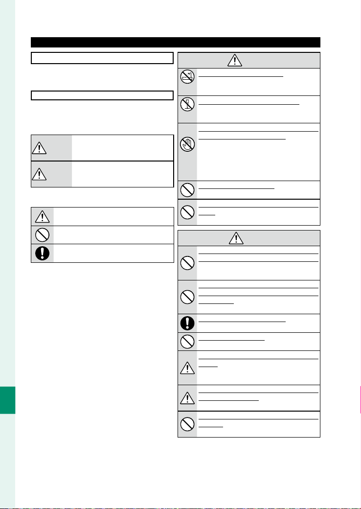
218
Technical Notes
10
Be sure to read these notes before using the lens
Safety Notes
•
Make sure that you use the lens correctly. Read these safety
notes and the camera Owner’s Manual carefully before use.
•
After reading these safety notes, store them in a safe place.
About the Icons
The icons shown below are used in this document to indicate
the severity of the injury or damage that can result if the in-
formation indicated by the icon is ignored and the product is
used incorrectly as a result.
WARNING
WARNING
This icon indicates that death or serious
injury can result if the information is ig-
nored.
CAUTION
CAUTION
This icon indicates that personal injury or
material damage can result if the informa-
tion is ignored.
The icons shown below are used to indicate the nature of the
instructions which are to be observed.
Triangular icons tell you that this information re-
quires attention (“Important”).
Circular icons with a diagonal bar tell you that the
action indicated is prohibited (“Prohibited”).
Filled circles with an exclamation mark indicate an
action that must be performed (“Required”).
WARNING
WARNING
Do not
immerse
Do not immerse in or expose to water.
Do not immerse in or expose to water. Failure to ob-
serve this precaution can cause a fi re or electric
shock.
Do not
disassemble
Do not disassemble (do not open the case).
Do not disassemble (do not open the case). Failure
to observe this precaution can cause fi re, electric
shock, or injury due to product malfunction.
Do not touch
internal
parts
Should the case break open as the result of a fall or other
Should the case break open as the result of a fall or other
accident, do not touch the exposed parts.
accident, do not touch the exposed parts. Failure to ob-
serve this precaution could result in electric shock
or in injury from touching the damaged parts. Re-
move the battery immediately, taking care to avoid
injury or electric shock, and take the product to the
point of purchase for consultation.
Do not place on unstable surfaces.
Do not place on unstable surfaces. The product may
fall, causing injury.
Do not view the sun through the lens or camera view-
Do not view the sun through the lens or camera view-
nders.
nders. Failure to observe this precaution can cause
permanent visual impairment.
CAUTION
CAUTION
Do not use or store in locations that are exposed to
Do not use or store in locations that are exposed to
steam, or smoke or are very humid or extremely dusty.
steam, or smoke or are very humid or extremely dusty.
Failure to observe this precaution can cause fi re or
electric shock.
Do not leave in direct sunlight or in locations subject
Do not leave in direct sunlight or in locations subject
to very high temperatures, such as in a closed vehicle
to very high temperatures, such as in a closed vehicle
on a sunny day.
on a sunny day. Failure to observe this precaution
can cause fi re.
Keep out of the reach of small children.
Keep out of the reach of small children. This product
could cause injury in the hands of a child.
Do not handle with wet hands.
Do not handle with wet hands. Failure to observe this
precaution can cause electric shock.
Keep the sun out of the frame when shooting backlit
Keep the sun out of the frame when shooting backlit
subjects.
subjects. Sunlight focused into the camera when
the sun is in or close to the frame can cause fi re
or burns.
When the product is not in use, replace the lens caps and
When the product is not in use, replace the lens caps and
store out of direct sunlight.
store out of direct sunlight. Sunlight focused by the
lens can cause fi re or burns.
Do not carry the camera or lens while they are attached
Do not carry the camera or lens while they are attached
to a tripod.
to a tripod. The product can fall or strike other ob-
jects, causing injury.
219
Technical Notes
10
For Your Safety
WARNING
WARNING
• INGESTION HAZARD: This product con-
tains a button cell or coin battery.
•
DEATH or serious injury can occur if in-
gested.
• A swallowed button cell or coin battery
can cause Internal Chemical Burns in as
little as 2hours.
• KEEP new and used batteries OUT OF
REACH of CHILDREN
• Seek immediate medical attention if a
battery is suspected to be swallowed or
inserted inside any part of the body.
L
Notes on the Built-in Battery
• This product contains a non-replaceable battery.
• The compatible battery type: MS621R
• The nominal battery voltage: 3V
•
Remove and immediately recycle or dispose of used batteries according to
local regulations and keep away from children.
Do NOT dispose of batteries in household trash or incinerate.
• Even used batteries may cause severe injury or death.
• Call a local poison control center for treatment information.
• Do not force discharge, disassemble, heat above 60 °C or incinerate.
Doing so may result in injury due to vending, leakage or explosion resulting
in chemical burns.
220
Technical Notes
10
For Your Safety
Statement of Compliance
Statement of Compliance
Manufacturer:
Manufacturer:
FUJIFILM Corporation
Address:
Address:
7-3, Akasaka 9-Chome Minato-Ku, Tokyo 107-0052, JAPAN
UK Authorized Representative:
UK Authorized Representative:
FUJIFILM UK Ltd.
Address:
Address:
Fujifi lm House, Whitbread Way, Bedford, Bedfordshire, MK42 0ZE, United Kingdom
Trade Mark:
Trade Mark:
FUJIFILM
Product Name:
Product Name:
DIGITAL FILMMAKING CAMERA
Product Model Number:
Product Model Number:
FF250002
Model Number:
Model Number:
GFX ETERNA 55
Support period:
Support period:
Seven years after the end of production
For details, refer to the website shown below.
https://repairs.fujifilm.eu/en/repairable-products/
We, Fuji lm Corporation, herewith declare under our sole responsibility that the product(s) identi ed in this declaration
conforms to the applicable security requirements in Schedule 1 of the following Regulations and Standards.
Regulations:
Regulations:
The Product Security and Telecommunications Infrastructure (Security Requirements
for Relevant Connectable Products) Regulations 2023
Standards:
Standards:
ETSI EN 303 645 V2.1.1 (2020-06)
(provision 5.1-1, 5.1-2, 5.2-1, 5.3-13)
Place: JAPAN
Place: JAPAN
(Signature)
Date: September 29, 2025
Date: September 29, 2025
(Name, Function)
Akihiro Kobayashi
General Manager of Quality Assurance Group,
Imaging Solutions Division
FUJIFILM Corporation

221
Technical Notes
10
Product Care
To ensure continued enjoyment of the product, observe
the following precautions.
•
Use a soft, dry cloth to clean the camera body and accessories
after each use. Do not use alcohol, thinner, benzene, insecticide
or other volatile chemicals, which could discolor, deteriorate, or
deform the product, or strip the paint.
•
Any liquid on the camera or accessories should be removed im-
mediately with a soft, dry cloth.
•
Use a blower brush or similar tool to remove dust from the LCD
monitor surface and other areas and then gently wipe with a
soft, dry cloth. Any remaining stains can be gently removed
with a small amount of lens-cleaning uid on a piece of Fuji lm
lens-cleaning paper.
•
The LCD monitor surface and other areas are delicate and prone
to scratches, so do not rub them with a hard object.
•
Use MAINTENANCE > SENSOR CLEANING in SET UP to clean
the sensor.
•
To prevent dust entering the camera, replace the body cap
when no lens is in place.
•
Use a blower to remove dust and lint from the glass surfac-
es of the lens. To remove smudges and ngerprints, apply a
small amount of lens cleaner to a soft, clean cotton cloth or
lens-cleaning tissue and clean from the center outwards using
a circular motion.

222
Technical Notes
10
Firmware Updates
When the rmware has been updated, and features have
been added and/or changed, update the rmware.
N
After updating to the latest rmware, the features of the camera may
di er somewhat from what is listed in this manual.
Downloading Firmware
First download the latest rmware and save it to a memory card.
For the method to download the rmware, refer to the following
website.
https://fujifilm-x.com/support/download/firmware/cameras/
Updating Firmware
Firmware can be updated in the following ways.
1
Insert a memory card containing the new fi rmware into the
camera.
2
Press MENU during shooting.
MENU options will be displayed on the
side monitors.

223
Technical Notes
10
Firmware Updates
3
Select SET UP > FIRMWARE UPDATE .
4
Select the target for fi rmware update.
5
A confi rmation dialog will be displayed.
Press two OK (Screen buttons4 and 6) to update the rm-
ware.
O
•
Use the battery with a su cient charge to update the rmware. Do
not turn o or operate the camera during an update. If the camera
is turned o during a rmware update, the camera may no longer
operate normally.
•
The time required for a rmware update depends on the size of the
rmware. At most, it may take about 10 minutes.
•
It is not possible to return to a previous version after the rmware has
been updated.
•
If an error message appears while the rmware is being updated, re-
fer to the following website.
https://fujifilm-x.com/support/download/error-message/

224
Technical Notes
10
Troubleshooting
Consult the table below should you encounter problems
using your camera. If you don’t nd the solution here, con-
tact your Fuji lm dealer.
Power and Battery
Power and Battery
Problem
Problem
Solution
Solution
The camera does not
turn on even when the
power switch is set to |.
•
The supplied battery is not charged at shipment. Charge
the battery before fi rst use.
•
Charge the supplied battery before use (P 32).
•
Reinsert the supplied battery in the correct orientation
(P 32).
•
Reinsert a fully-charged V-mount battery in the correct
orientation.
•
When using an AC power adapter, confi rm that the AC
power adapter and the AC cable are properly connected.
The supplied battery
runs down quickly.
•
Select MAINTENANCE > BATTERY AGE in SET UP to
view the battery age; if the battery is old, replace it with
a new battery.
The camera turns o
suddenly.
•
Check whether the battery is running out of power
(P 57).
•
When the camera temperature becomes high, it will au-
tomatically turn off .

225
Technical Notes
10
Troubleshooting
Shooting
Basic Shooting
Problem
Problem
Solution
Solution
Shooting is unavailable
when the REC button is
pressed.
•
Check the free space on the memory card.
•
Check whether the connected external device is ready for
recording.
Movie Recording
Problem
Problem
Solution
Solution
Video recording ended
unexpectedly.
Recording may stop if the writing speed of the storage me-
dia is slow. A list of supported storage media is available
on the Fujifi lm website. For details, refer to “COMPATIBILITY
(Cameras)”.
https://fujifilm-x.com/support/compatibility/cameras/
Abnormalities in Recorded Movies
Problem
Problem
Solution
Solution
Audio cannot be
recorded.
Noticeable noise in the
audio.
•
Check settigs for AUDIO SETTING .
•
Confi rm that the microphone is not blocked during re-
cording.

226
Technical Notes
10
Playback
Movie Playback
Problem
Problem
Solution
Solution
Unable to play back
movies.
Movie clip playback may be unavailable if the clip was re-
named or edited, or if its folder was renamed via a comput-
er or other cameras.
Wireless Transfer
For additional information on troubleshooting wireless connec-
tions, visit:
https://digitalcamera-support-en.fujifilm.com/
Uploading Files
Problem
Problem
Solution
Solution
Cannot upload les.
•
Check that the network settings are correct.
•
The signal strength may be poor. Move the camera to an-
other location and try again.
•
Ensure the camera clock is set correctly.

227
Technical Notes
10
Troubleshooting
Miscellaneous
Camera Operation
Problem
Problem
Solution
Solution
The camera is unre-
sponsive.
•
Remove and reinsert the battery (P 32).
•
Use the lock switch to unlock the controls (P 15).
The camera does not
function as expected.
Remove the battery and any accessories attached to the
camera, then reattach only the minimum necessary acces-
sories and reinsert the battery before operating the camera
(P 32). If the problem persists, contact your Fujifi lm
dealer.

228
Technical Notes
10
Warning Messages and Displays
The following warnings appear in the display.
Warning
Warning
Description
Description
i (red)
Low battery. Charge the battery or insert a fully-charged
spare battery.
j (red)
Battery exhausted. Charge the battery or insert a ful-
ly-charged spare battery.
s (displayed in red with
red focus frame)
The camera cannot focus. Focus on another subject at the
same distance, then recompose the shot.
Aperture or shutter
speed displayed in red
The subject is too bright or too dark. Movies can be shot,
but will be over- or under-exposed.
FOCUS ERROR
Camera malfunction. Turn the camera off and then on
again. If the problem persists, contact your Fujifi lm dealer.
LENS CONTROL ERROR
TURN OFF THE CAMERA
AND TURN ON AGAIN
MEDIA NOT INITIALIZED
•
The memory card is not formatted or the memory card has been
formatted in a computer or other device: Format the memory
card in the camera.
•
The memory card contacts require cleaning: Clean the con-
tacts with a soft, dry cloth. If the message is repeated,
format the card. If the message persists, replace the card.
•
Camera malfunction: Contact your Fujifi lm dealer.

229
Technical Notes
10
Warning Messages and Displays
Warning
Warning
Description
Description
MEDIA ERROR
•
The memory card is not formatted for use in the camera: For-
mat the card.
•
The memory card contacts require cleaning or the memory card
is damaged: Clean the contacts with a soft, dry cloth. If the
message is repeated, format the card. If the message per-
sists, replace the card.
•
Incompatible memory card: Use a compatible card.
•
Camera malfunction: Contact your Fujifi lm dealer.
PROTECTED MEDIA The memory card is locked. Unlock the card.
MEMORY FULL
The memory card is full and pictures cannot be recorded.
Delete pictures or insert a memory card with more free
space.
WRITE ERROR
•
Memory card error or connection error: Reinsert the card or
turn the camera off and then on again. If the message
persists, contact your Fujifi lm dealer.
•
Not enough memory remaining to record additional les: De-
lete fi les or insert a memory card with more free space.
•
The memory card was removed while data were being recorded:
Do not remove the memory card during recording.
•
The memory card write speed is slow: When recording mov-
ies, be sure the memory card write speed is fast enough.

230
Technical Notes
10
Warning Messages and Displays
Warning
Warning
Description
Description
READ ERROR
•
The le is corrupt or was not created with the camera: The fi le
cannot be viewed.
•
The memory card contacts require cleaning: Clean the con-
tacts with a soft, dry cloth. If the message is repeated,
format the card. If the message persists, replace the card.
•
Camera malfunction: Contact your Fujifi lm dealer.
p (yellow)
CAMERA IS APPROACHING
HIGH TEMPER-
ATURE LIMIT.DO NOT
HOLD CAMERA FOR
LONG PERIODS OF TIME
The camera is approaching the maximum temperature al-
lowed. Remaining in contact with the camera could result
in low-temperature burns; do not continue holding the
camera. The camera will shortly turn off automatically. Turn
the camera off and wait for it to cool. Mottling may increase
in pictures taken when this warning is displayed.
p (red)
HIGH TEMPERATURE
LIMIT REACHED
SHUTTING DOWN
The camera temperature has reached the cutoff point and
the camera is about to turn off automatically. Turn the cam-
era off and wait for it to cool. Mottling may increase in pic-
tures taken when this warning is displayed.

231
Technical Notes
10
Errors
If a C icon appears in the display, select NETWORK > ERROR
DESCRIPTION to view the error and then take the appropri-
ate action.
Error
Error
Solution
Solution
NOT CONNECTED TO
NETWORK VIA WIRELESS
LAN
•
No connection to access point: Confi rm that the access point
is on, verify its settings and IP address, and check that
there are no obstructions blocking its signal. If necessary,
move the camera closer to the access point.
•
Camera settings have not been correctly adjusted for connec-
tion to the access point: Check that the password, encryp-
tion type, and SSID match those chosen for the access
point.
IP ADDRESS CANNOT
BE ASSIGNED BY DHCP
SERVER OR THERE IS AN
ISSUE WITH IP ADDRESS
SETTING PLEASE CHECK
SETTINGS
•
No DHCP server: If there is no DHCP server on the network,
enter the IP address and other information manually.
•
The DHCP server is down: Contact the network administra-
tor.
CA ROOT CERTIFICATE IS
INVALID
The root certi cate has expired: After confi rming that the
camera clock is set to the correct time and date, load an
updated CA root certifi cate.

232
Technical Notes
10
Errors
Error
Error
Solution
Solution
Frame.io DISCONNECTED
•
The Frame.io server may be down: Check that the Frame.io
server is up or try again later.
•
The camera clock is not set to the correct time and date: Set the
camera clock.
•
The network is not con gured correctly: Check the settings of
the connected network.
•
Turn the camera off and then on again.
•
Contact the network administrator.
UNEXPECTED ERROR HAS
OCCURRED
•
Turn the camera off and then on again.
•
Contact the network administrator.

233
Technical Notes
10
Standard Recording Time
The standard recording time is approximate. The actual re-
cording time varies depending on the recording conditions
and the type of memory card used. Also, the time displayed
on the LCD monitor may not diminish at an even rate.
Capacity
Capacity
Settings
Settings
SD/CFexpress memory cards
SD/CFexpress memory cards
512GB
512GB
ProRes HQ 4K 24P
ProRes HQ 4K 24P Approx. 85 minutes
H.265 720Mbps
H.265 720Mbps Approx. 100 minutes
O
•
The types of memory cards available vary with the settings selected
(P 42).
•
Depending on the bit rate, shots saved to memory cards with a capacity
of 32 GB or less may be recorded across multiple les without interruption.
The same is true of shots over an hour in length, independent of the bit
rate and memory card capacity.

234
Technical Notes
10
Speci cations
System
Model FUJIFILM GFX ETERNA 55
Product Number FF250002
Image sensor 43.8 mm× 32.9 mm Bayer array with primary color fi lter
Storage media Fujifi lm-recommended SD/SDHC/SDXC and CFexpress Type B
memory cards
Memory card slots
•
SD memory card slot (UHS-II compliant) ×1
•
CFexpress memory card slot (Type B) ×1
File system
•
Container format: MOV, MXF
•
Codec: Compliant with HEVC/H.265 and ProRes
•
Audio: LPCM (two channels: 24-bit, 48kHz sampling)
•
Audio (via XLR microphone adapter): LPCM (two channels:
24-bit, 48kHz sampling; four channels: 24-bit, 48kHz sam-
pling)
•
Still pictures: Compliant with JPEG
Lens mount FUJIFILM G mount
Sensitivity Standard output sensitivity equivalent to ISO400 – 12800 in
increments of ⁄EV; AUTO ; extended output sensitivity equiva-
lent to ISO 100, 320, 25600
Metering 256-segment through-the-lens (TTL) metering;
MULTI , CENTER WEIGHTED , SPOT , AVERAGE
Exposure compensation
−2EV – +2EV in increments of ¼ EV

235
Technical Notes
10
Speci cations
System
Shutter speed
•
Electronic shutter
•
Shutter speed: ⁄s to ⁄s
•
Shutter angle: 5.6 degrees to 360 degrees
Focus
•
Mode: Continuous AF; manual focus with focus ring
•
Autofocus system: Intelligent hybrid AF (TTL contrast-detect/
phase-detection AF)
•
Focus-area selection: MULTI , TRACKING , AREA
White balance
Auto ( WHITE PRIORITY , AUTO , AMBIENCE PRIORITY ), color tem-
perature selection (2000 K to 11000 K), CC (−16.00 to +16.00),
custom
Self-timer Off , 3 sec., 5 sec., 10 sec.
LCD monitor 3-in/7.6 cm, 720 × 480-dot color touch screen LCD monitor
In-body ND lter
•
CLEAR
•
Electronic variable ND lter: 0.6(ND4) to 2.1(ND128)
Movies
(with stereo sound)
•
Resolution: 8K 2.76 : 1, 8K 2.39 : 1, 8K 16 : 9, 8K 17 : 9, 6.3K 16 : 9,
5.8K 2.39 : 1, 5.4K 17 : 9, 4.8K 3 : 2, 4.8K 16 : 9, 4.6K 1.38 : 1,
4K 4 : 3, 4K 16 : 9, 4K 17 : 9, 4K 1.195 : 1, FHD 16 : 9, FHD 17 : 9
O
The size that can be selected depends on the
IMAGE FORMAT setting.
•
Frame rate: 59.94P, 50P, 48P, 47.95P, 29.97P, 25P, 24P, 23.98P
•
Recording format:
-
H.265 (10-bit MOV/MXF 4 : 2 : 2; 720, 360, 200, 100, or
50Mbps)
-
ProRes 422 HQ, ProRes 422, ProRes 422 LT (10-bit MOV/
MXF 4 : 2 : 2)
•
Output format: HDMI/SDI output supported (RAW output
supported with Atomos and Blackmagic Design external re-
corders; 10-bit 4 : 2 : 2)

236
Technical Notes
10
Input/output terminals
Microphone connector
⌀3.5 mm mini-stereo jack
Headphone jack socket
⌀3.5 mm mini-stereo jack
Remote release connector
⌀2.5 mm 3-pole mini jack
Digital input/output USB connector: USB Type-C® USB 10 Gbps
LAN connector 1000BASE-T, 100BASE-TX, 10BASE-T
SDI connector BNC type
HDMI output HDMI connector (Type A)
TC IN/TC OUT connector
BNC type
Genlock connector BNC type
Lens connector 12-pin
DC OUT connector LEMO 2-pin, 12 V, 3 A
DC IN connector 4-pin

237
Technical Notes
10
Speci cations
Power supply/other
Power supply
•
NP-W235 rechargeable battery (supplied with camera)
•
V-mount battery (sold separately)
•
AC-15VS AC power adapter (supplied with camera)
Power consumption
•
Standard power consumption: 21W (Lens included, 4K 16:9, 59.94P,
ProRes HQ, COOLING FAN SETTING AUTO1 , excluding peripherals other than
the LCD monitor and handle)
•
Maximum power consumption: 49W (Lens included, 4K 16:9, 59.94P,
ProRes HQ, COOLING FAN SETTING HIGH , including peripherals, DC OUT 12 V
connector disconnected)
Camera size
(W × H × D)
110.8 mm× 138.2 mm× 176.8 mm/4.36 in.× 5.44 in.× 6.96 in.
Camera weight Approx. 2.0 kg/70.5 oz., excluding battery, accessories, and
memory card
Operating conditions
•
Temperature: −10 °C to +40 °C/+14 °F to +104 °F (+5 °C to
+40 °C/+41 °F to +104 °F when battery is charging)
•
Humidity: 10% to 80% (no condensation)

238
Technical Notes
10
Wireless transmitter
Wireless LAN
Standards IEEE 802.11a/b/g/n/ac (standard wireless protocol)
Operating frequency
(center frequency)
•
USA, Canada, Brazil, China, India, Korea, Malaysia, Indonesia
: 2,412 MHz–2,462 MHz (11 channels)
: 5,180 MHz–5,320 MHz (W52, W53)
: 5,745 MHz–5,825 MHz (UNII-3)
•
European Union, Japan, United Kingdom, Australia, Norway, New
Zealand, Turkey, Hong Kong, Philippines, Vietnam, Singapore,
Thailand, UAE, Russia, Taiwan, Saudi Arabia, Qatar, Bahrain,
Oman, Egypt, Iran, Kuwait, Lebanon, Uzbekistan, Israel
: 2,412 MHz–2,462 MHz (11 channels)
: 5,180 MHz–5,320 MHz (W52, W53)
: 5,500 MHz–5,700 MHz (W56)
Access protocols Infrastructure
Bluetooth®
Standards Bluetooth version 4.2 (Bluetooth Low Energy)
Operating frequency
(center frequency)
2,402 MHz–2,480 MHz

239
Technical Notes
10
Speci cations
NP-W235 rechargeable battery
Nominal voltage 7.2 V
Nominal capacity 2350 mAh
Rating capacity 2200 mAh
Operating
temperature
0 °C to +40 °C/+32 °F to +104 °F
Dimensions
(W × H × D)
38.92 mm× 22.8 mm× 52.26 mm/
1.5 in.× 0.9 in.× 2.1 in.
Weight Approx. 79 g/2.8 oz.
AC-15VS AC power adapter
Manufacturer Adapter Technology Co., Ltd.
Address 6F, No.258, Liancheng Rd., Zhonghe Dist., New
Taipei City 235, Taiwan
Model name ATS160A1-P150
Rated input AC 100V-240V 50/60Hz
Rated output DC 15.0V 10.0A 150W
Average active e ciency 88 %
E ciency at load 10% 79 %
No-load power consumption 0.15 W
Operating temperature −10 °C to +40 °C/+14 °F to +104 °F
Dimensions (W × H × D) 66.0mm× 34.8mm× 164.5mm
/
2.6 in.× 1.4 in.× 6.5 in. (excluding projections)
Weight Approx. 500 g/17.6 oz. (without the connection cord)

240
Technical Notes
10
Speci cations
VF-GFXC1 LCD monitor
LCD monitor 5-in/12.7 cm, 6220 k-dot color touch screen LCD
monitor
Dimensions (W × H × D) 142.5mm× 85.1mm× 30.6mm
/5.61 in.×
3.35 in.× 1.20 in.
(excluding cables)
Weight Approx. 310 g/10.9 oz.
RH-GFXC1 handle
Hot shoe Provided
Dimensions (W × H × D) 197.4mm× 87.5mm× 69.8mm
/
7.78 in.× 3.44 in.× 2.75 in.
(excluding cables)
Weight Approx. 505 g/17.8 oz.
PL MOUNT ADAPTER G PL-mount adapter
Dimensions (W × H × D) 94.2mm (including PL lock levers)× 81.4mm (not including
PL lock levers)× 37.1mm (PL-mount adapter)
/
3.71 in.× 3.20 in.× 1.46 in.
Weight Approx. 246 g/8.7 oz. (PL-mount adapter only)
O
Speci cations and performance are subject to change without notice.
Fuji lm will not be held liable for any errors this manual may contain.
The appearance of the product may di er from that described in this
manual.
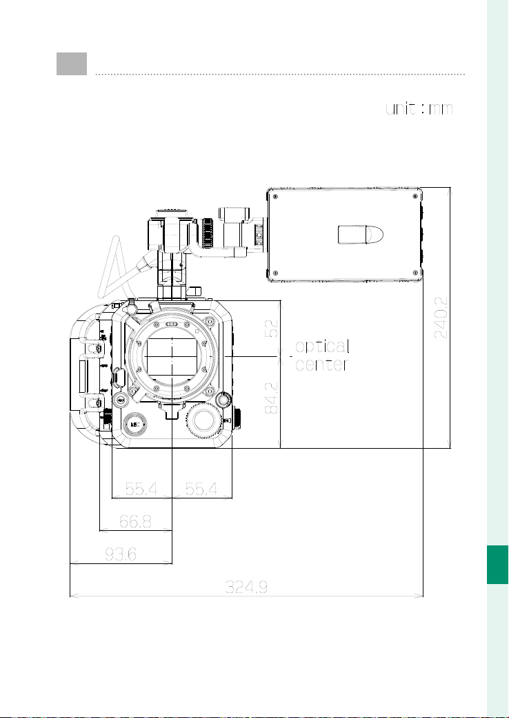
241
Technical Notes
10
External dimensions
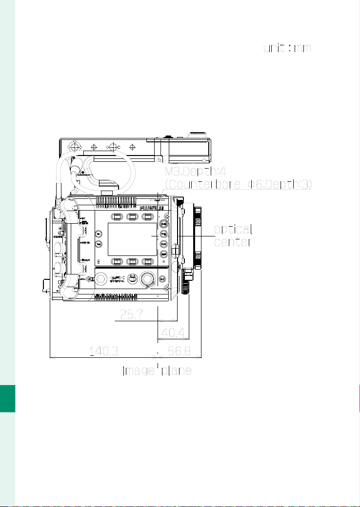
242
Technical Notes
10
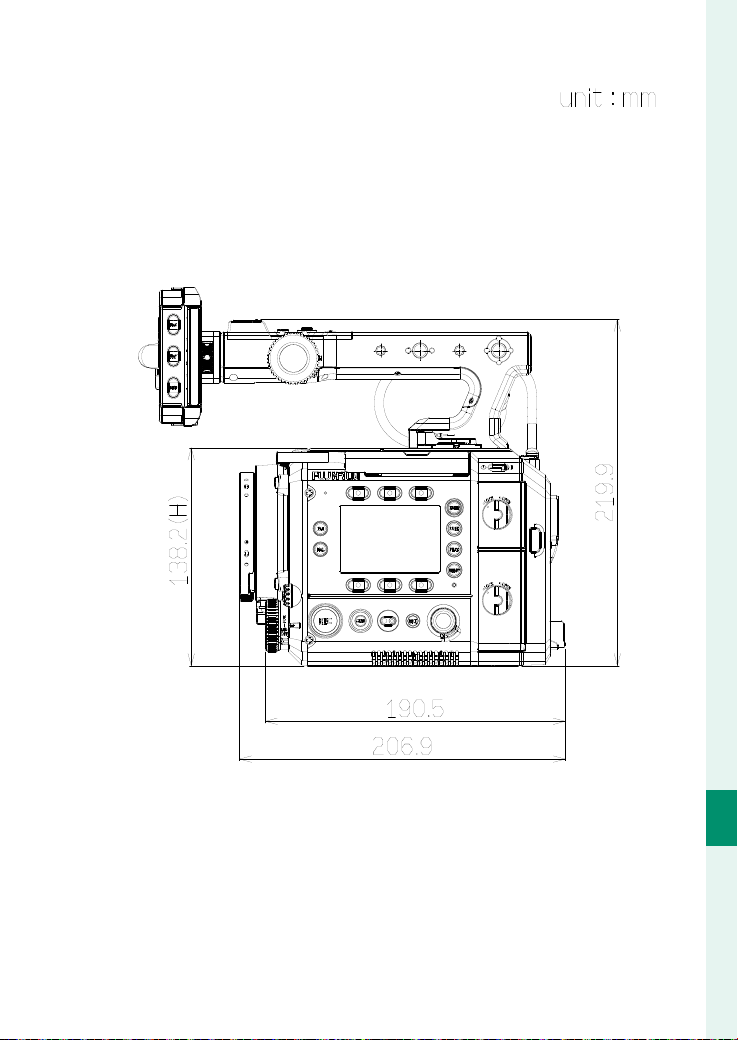
243
Technical Notes
10
External dimensions
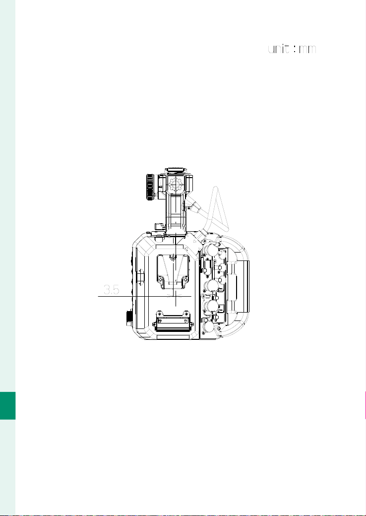
244
Technical Notes
10
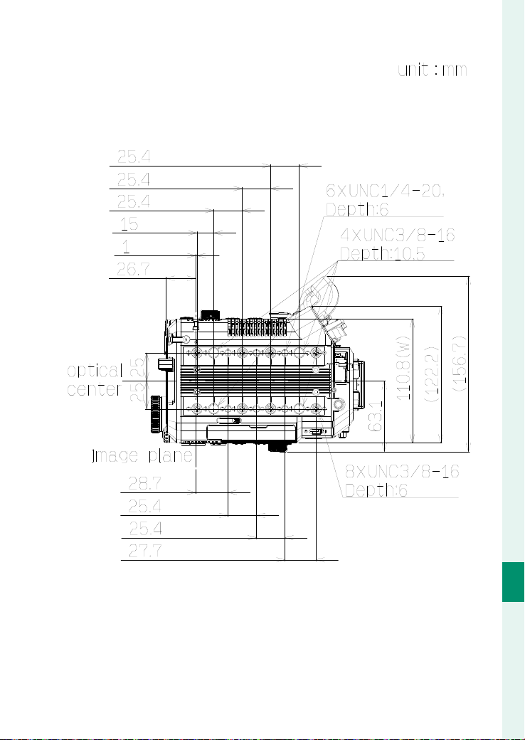
245
Technical Notes
10
External dimensions
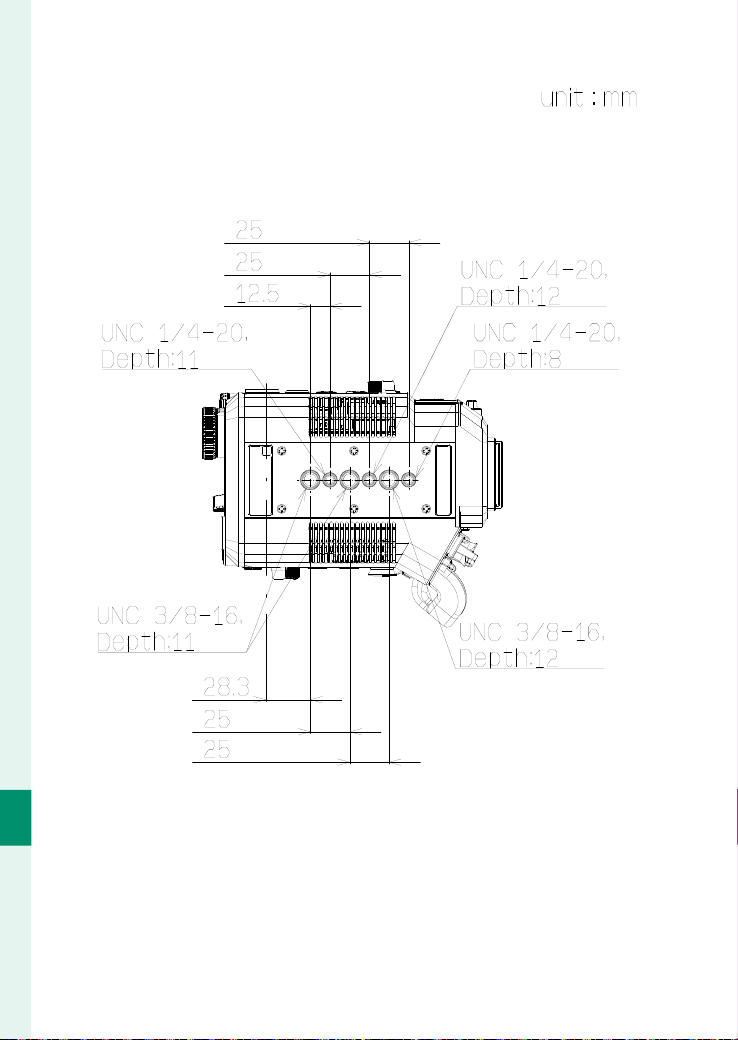
246
Technical Notes
10
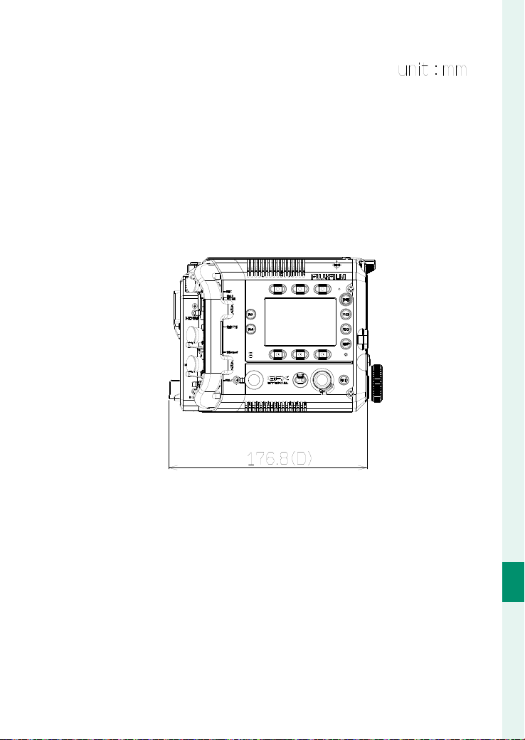
247
Technical Notes
10
External dimensions
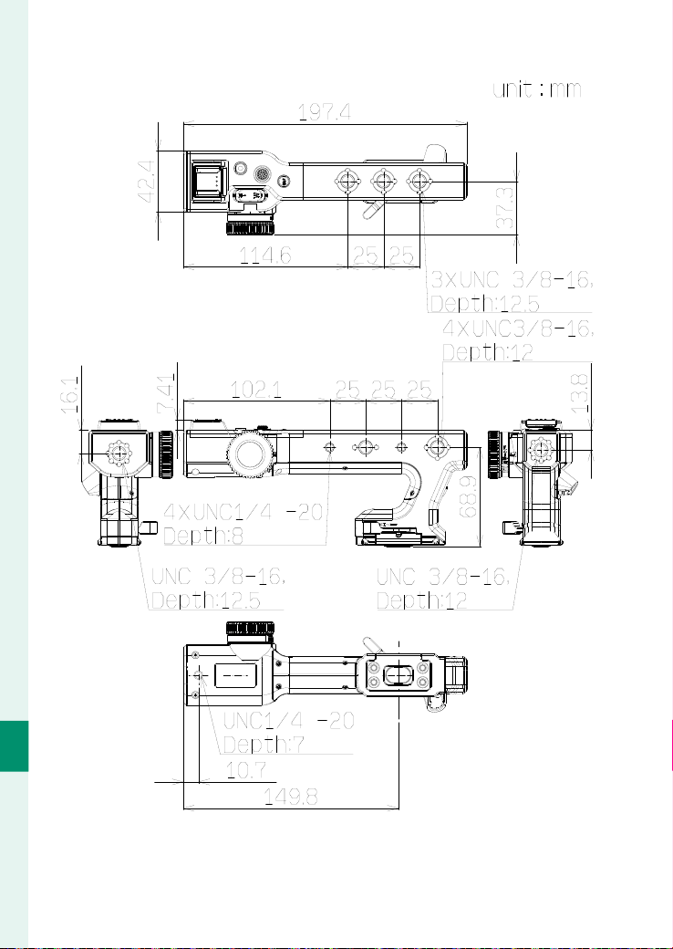
248
Technical Notes
10
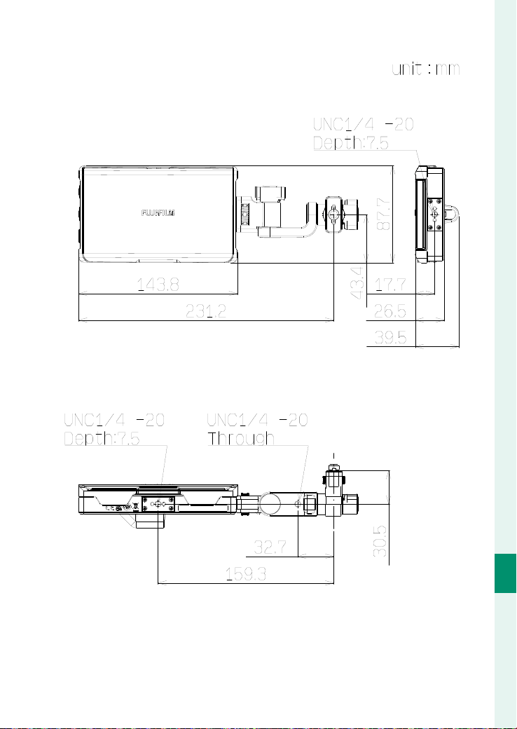
249
Technical Notes
10
External dimensions

7-3, AKASAKA 9-CHOME, MINATO-KU, TOKYO 107-0052, JAPAN
https://fujifilm-x.com