EnglishEspañol
한국어
Deutsch
Português
��中�
Français
简体中�
Рycский
Owner's Manual
Benutzerhandbuch
Mode d’emploi
Manual de instrucciones
Manual do Proprietário
Руководство пользователя
使用说明书
사용설명서
使用說明書
Be sure to read the “PRECAUTIONS” on page 6.
Die „VORSICHTSMASSNAHMEN“ auf Seite 6 lesen.
Veillez à lire les « PRÉCAUTIONS D’USAGE » à la page 6.
Asegúrese de leer “PRECAUCIONES” en la página 6.
Certifique-se de ler as "PRECAUÇÕES" na página 6.
Обязательно прочтите «ПРАВИЛА ТЕХНИКИ БЕЗОПАСНОСТИ» на стр. 6.
请务必阅读� 6 页的 ���事项�。
6페이지의“안전 주의사항” 을 반드시 읽어 주십시오 .
�務必��� 6 頁的「��事項」�
ZH-TWPT ZH-CNFREN KOES RUDE
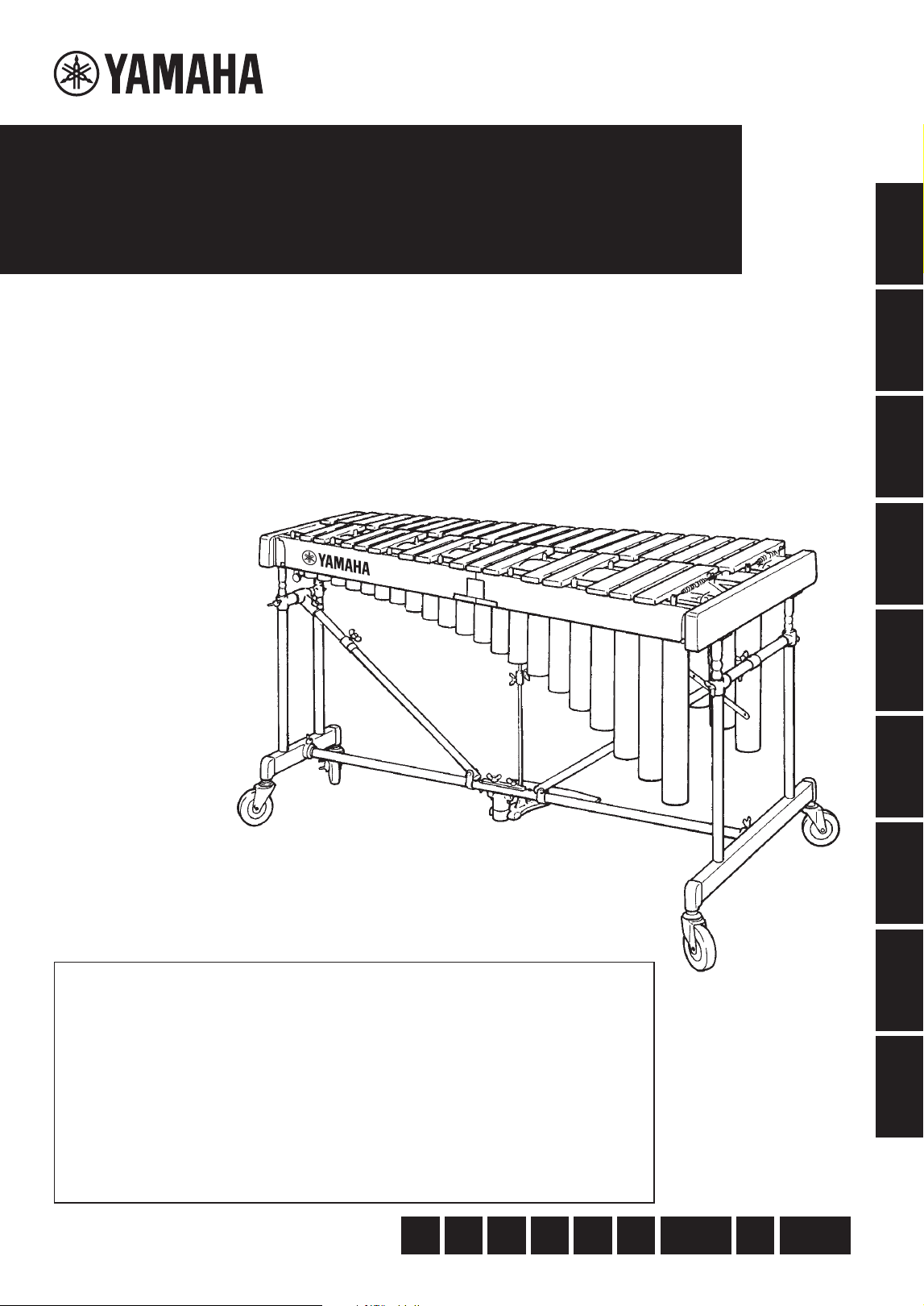
CONCERT
VIBRAPHONE
YV-4110
(
M
)
YV-3910
(
M
)
YV-3710
(
M
)
YV-2700
(
G
)
2 •
YV-4110(M) YV-3910(M) YV-3710(M) YV-2700(G)
FCC INFORMATION (U.S.A.)
1. IMPORTANT NOTICE: DO NOT MODIFY THIS UNIT! This product, when
installed as indicated in the instructions contained in this manual, meets FCC
requirements. Modifications not expressly approved by Yamaha may void your
authority, granted by the FCC, to use the product.
2. IMPORTANT: When connecting this product to accessories and/or another
product use only high quality shielded cables. Cable/s supplied with this product
MUST be used. Follow all installation instructions. Failure to follow instructions
could void your FCC authorization to use this product in the USA.
3. NOTE: This product has been tested and found to comply with the require-
ments listed in FCC Regulations, Part 15 for Class “B” digital devices. Compli-
ance with these requirements provides a reasonable level of assurance that
your use of this product in a residential environment will not result in harmful
interference with other electronic devices. This equipment generates/uses radio
frequencies and, if not installed and used according to the instructions found in
the users manual, may cause interference harmful to the operation of other
electronic devices. Compliance with FCC regulations does not guarantee that
interference will not occur in all installations. If this product is found to be the
source of interference, which can be determined by turning the unit “OFF” and
“ON”, please try to eliminate the problem by using one of the following measures:
- Relocate either this product or the device that is being affected by the
interference.
- Utilize power outlets that are on different branch (circuit breaker or fuse)
circuits or install AC line filter/s.
- In the case of radio or TV interference, relocate/reorient the antenna. If the
antenna lead-in is 300 ohm ribbon lead, change the lead-in to co-axial type
cable.
If these corrective measures do not produce satisfactory results, please
contact the local retailer authorized to distribute this type of product. If you
cannot locate the appropriate retailer, please contact Yamaha Corporation of
America, 6600 Orangethorpe Avenue, Buena Park, CA 90620, U.S.A.
The above statements apply ONLY to those products distributed by Yamaha
Corporation of America or its subsidiaries.
(529-M04 FCC class B YCA 02)
COMPLIANCE INFORMATION STATEMENT
(Supplierʼs declaration of conformity procedure)
Responsible Party: Yamaha Corporation of America
Address: 6600 Orangethorpe Avenue, Buena Park, CA. 90620, U.S.A.
Telephone: 714-522-9011
Type of Equipment: Concert Vibraphone
Model Name: YV-4110(M) YV-3910(M) YV-3710(M) YV-2700(G)
This device complies with Part 15 of the FCC Rules.
Operation is subject to the following two conditions:
1) this device may not cause harmful interference, and
2) this device must accept any interference received, including interference that may cause undesired operation.
(529-M02 FCC sdoc YCA 02)
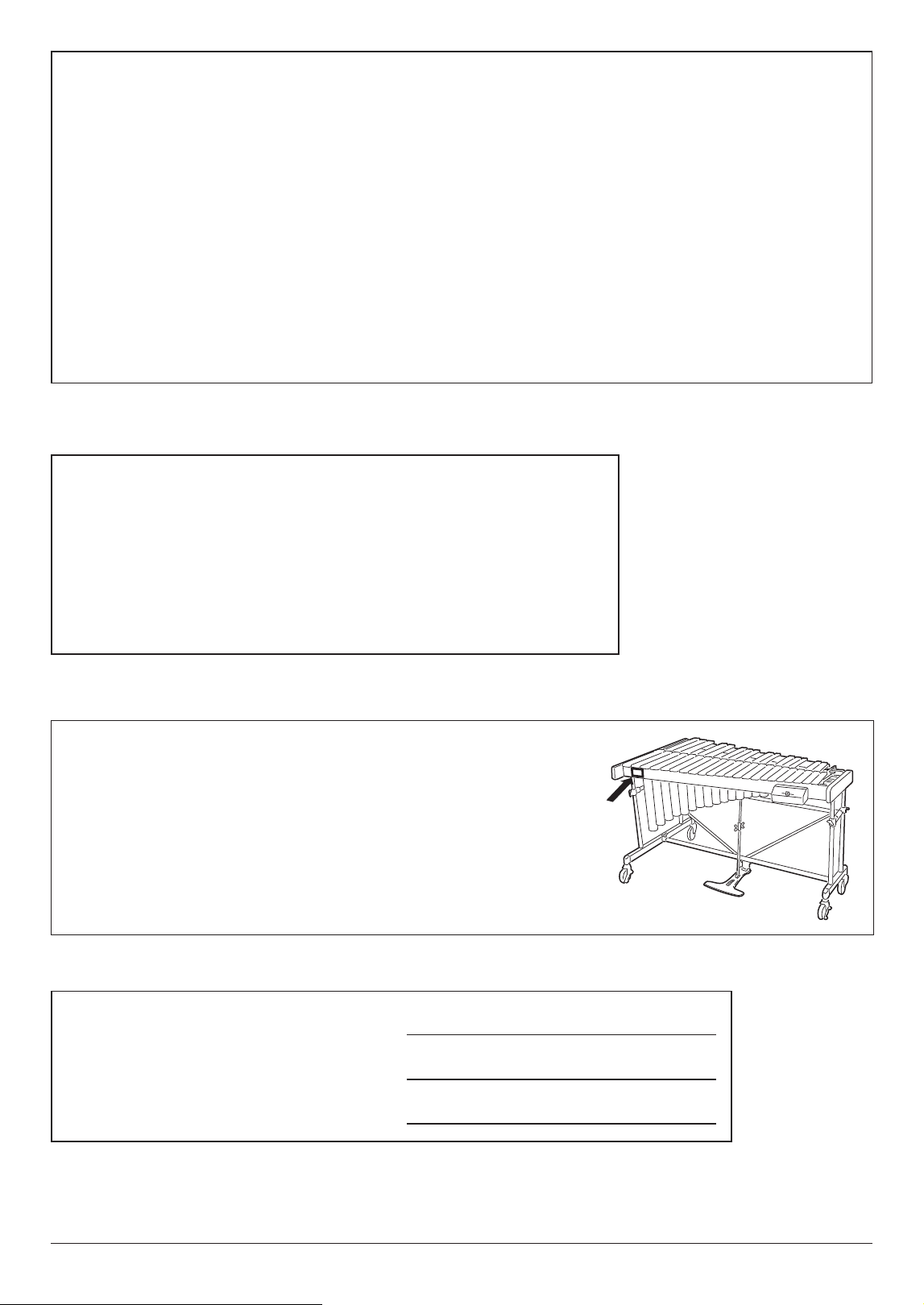
The name plate is located on the player side of the product.
Das Typenschild befindet sich an der Spielerseite des Instruments.
La plaque de modèle est située sur le côté musicien du produit.
La placa de identificación está situada en el lado del músico del producto.
A placa de identificação está localizada na lateral do player do produto.
Фирменная табличка изделия расположена на стороне исполнителя.
铭牌位于产品的演奏者侧。
명판은 본 제품의 연주자측에 위치하고 있습니다 .
銘牌位於產品的演奏者側。
The model number, serial number, power re-
quirements, etc., are located on this plate. You
should record the model number, serial number,
and the date of purchase in the spaces provided
at right and retain this manual as a permanent
record of your purchase.
Model No.
Serial No.
Purchase Date
YV-4110(M) YV-3910(M) YV-3710(M) YV-2700(G)
• 3
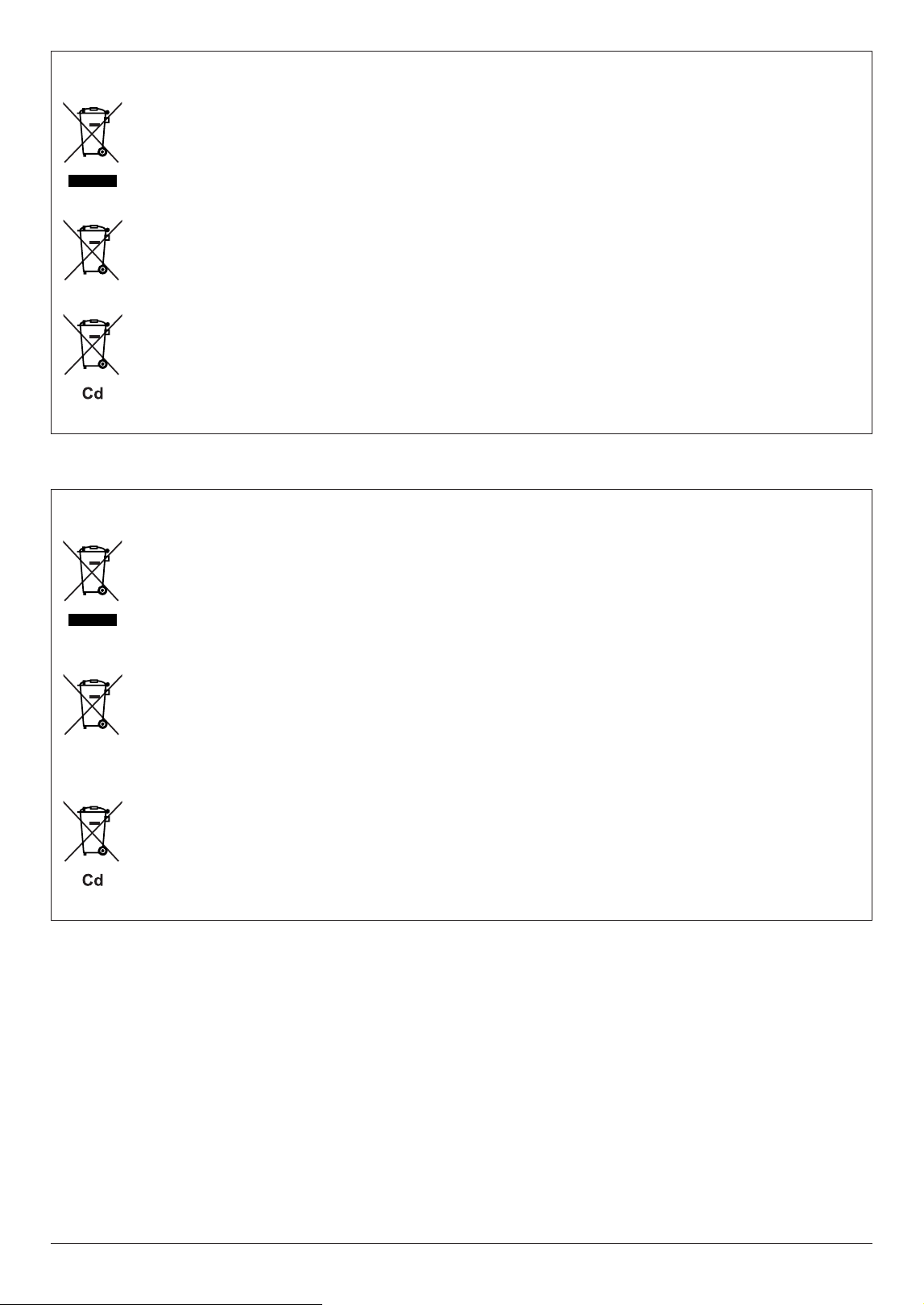
Information for users on collection and disposal of old equipment and used batteries:
These symbols on the products, packaging, and/or accompanying documents mean that used electrical and electronic
products and batteries should not be mixed with general household waste.
For proper treatment, recovery and recycling of old products and used batteries, please take them to applicable collec-
tion points, in accordance with your national legislation.
By disposing of these products and batteries correctly, you will help to save valuable resources and prevent any potential
negative effects on human health and the environment which could otherwise arise from inappropriate waste handling.
For more information about collection and recycling of old products and batteries, please contact your local municipality,
your waste disposal service or the point of sale where you purchased the items.
For business users in the European Union:
If you wish to discard electrical and electronic equipment, please contact your dealer or supplier for further information.
Information on Disposal in other Countries outside the European Union:
These symbols are only valid in the European Union. If you wish to discard these items, please contact your local au-
thorities or dealer and ask for the correct method of disposal.
Note for the battery symbol (bottom two symbol examples):
This symbol might be used in combination with a chemical symbol. In this case it complies with the requirement set by
the EU Battery Directive for the chemical involved.
(58-M03 WEEE battery en 01)
Información para usuarios sobre la recogida y eliminación de los equipos antiguos y las pilas usadas
Estos símbolos en los productos, embalajes y documentos anexos significan que los productos eléctricos y electrónicos
y sus pilas no deben mezclarse con los desperdicios domésticos normales.
Para el tratamiento, recuperación y reciclaje apropiados de los productos antiguos y las pilas usadas, llévelos a puntos
de reciclaje correspondientes, de acuerdo con la legislación nacional.
Al deshacerse de estos productos y pilas de forma correcta, ayudará a ahorrar recursos valiosos y a impedir los posibles
efectos desfavorables en la salud humana y en el entorno que de otro modo se producirían si se trataran los desperdi-
cios de modo inapropiado.
Para obtener más información acerca de la recogida y el reciclaje de los productos antiguos y las pilas, póngase en
contacto con las autoridades locales, con el servicio de eliminación de basuras o con el punto de venta donde adquirió
los artículos.
Para los usuarios empresariales de la Unión Europea:
Si desea desechar equipos eléctricos y electrónicos, póngase en contacto con su vendedor o proveedor para obtener
más información.
Información sobre la eliminación en otros países fuera de la Unión Europea:
Estos símbolos solamente son válidos en la Unión Europea. Si desea desechar estos artículos, póngase en contacto con
las autoridades locales o con el vendedor y pregúnteles el método correcto.
Nota sobre el símbolo de pila (dos ejemplos de símbolos en la parte inferior):
Este símbolo se puede utilizar en combinación con un símbolo químico. En este caso, cumple el requisito establecido
por la Directiva de la UE sobre pilas correspondiente a la sustancia química utilizada.
(58-M03 WEEE battery es 01)
6 •
YV-4110(M) YV-3910(M) YV-3710(M) YV-2700(G)
Owner's Manual
PRECAUTIONS
Please follow the following instructions to ensure that you are using your vibraphone in a safe manner.
A responsible adult should provide proper instruction on how to properly use and treat
the instrument before allowing a child to play the instrument.
In order to prevent fire, electric shock, or injury,
make sure that all precautions described below are followed.
WARNING
Disregarding warnings denoted with this mark and misusing the
product could possibly lead to death or serious injury.
• Before using the vibraphone, please thoroughly read the
following instructions and the Owner’s Manual.
• Do not dismantle or modify the vibraphone’s controller or
driver. Doing so could cause fire or electric shock.
• Repairs or part replacement should not be attempted unless
instructions are provided in the manual.
• Do not use or store the instrument in any of the following
locations. Doing so could cause fire or electric shock.
- Places subject to high temperatures (near a heating
device or in direct sunlight, etc.).
- Places in which the instrument may be exposed to mois-
ture (bathroom, on wet floors, etc.) or excessive humidity.
- Places in which the instrument may be exposed to rain.
- Places with excessive dust.
- Places subject to excessive vibration.
• When using the AC adapter, do not bend the power cord
excessively, or place heavy objects on the cord. Doing so
may damage the cord and cause fire or electric shock.
• Do not play or roughhouse around the instrument. Bumping
into the instrument could cause injury. It could also cause
the instrument to overturn. Do not allow children to play
around the instrument.
• Do not lean against or climb onto the instrument. Doing so
could cause the instrument to overturn and result in serious
injury.
• Never put foreign objects (combustible objects, coins, wire,
etc.) or liquids (water, juice, etc.) in the drive unit. Doing so
could cause fire and electric shock.
• If one of the following occurs, turn off the power, unplug the
AC adapter and request repair as soon as possible.
- If the AC adapter or power cord becomes damaged.
- If foreign objects or liquids have entered the drive unit.
- If the drive unit gets wet (rain, etc.).
- If the drive unit operates abnormally or is broken.
• Never place the instrument on a sloping or unstable surface
or platform, etc. Doing so could cause the instrument to
overturn and result in injury.
• When moving the instrument on its casters,
1. Only move across smooth, flat surfaces. Hold the instru-
ment by its side frames and push forward slowly.
2. Avoid moving the instrument on surfaces that are sloped
or uneven. The instrument could overturn, run out of con-
trol, and create a dangerous hazard.
3. Never run with the instrument. The instrument may be-
come impossible to control and crash into a wall causing
serious injury.
• If the instrument must be lifted or carried, do so with two or
more people using both hands to lift it by the side frames.
DMI-7
1/2
YV-4110(M) YV-3910(M) YV-3710(M) YV-2700(G)
Owner's Manual
• 7
CAUTION
Disregarding warnings denoted with this mark and misusing the
product could result in injury or property damage.
• Do not use the instrument in locations with poor ventilation.
• Never pull on the cord when disconnecting the AC adapter
from an outlet. Always hold the AC adapter when connecting
or disconnecting the power.
• Always disconnect the AC adapter from the outlet when the
instrument is not used for an extended period of time.
• Always use an AC adapter that meets Yamaha specifica-
tions. The use of any other AC adapter could cause damage.
• Never place your hands or feet underneath the pedal. Doing
so could result in pinched hands or feet.
• Never touch the rotating fans. Doing so could result in
pinched fingers, etc.
• Never use the mallets for anything other than playing the in-
strument. Doing so could result in injury or accidents. Do not
allow children to use the mallets in any way that may pose a
danger to themselves or others.
• Lock the stoppers on the casters when the instrument is not
in use.
• When adjusting the playing surface height (described on
page 19), make sure that the procedure is performed by
at least two persons. Attempting to adjust the height alone
could result in the instrument overturning, creating a danger-
ous hazard.
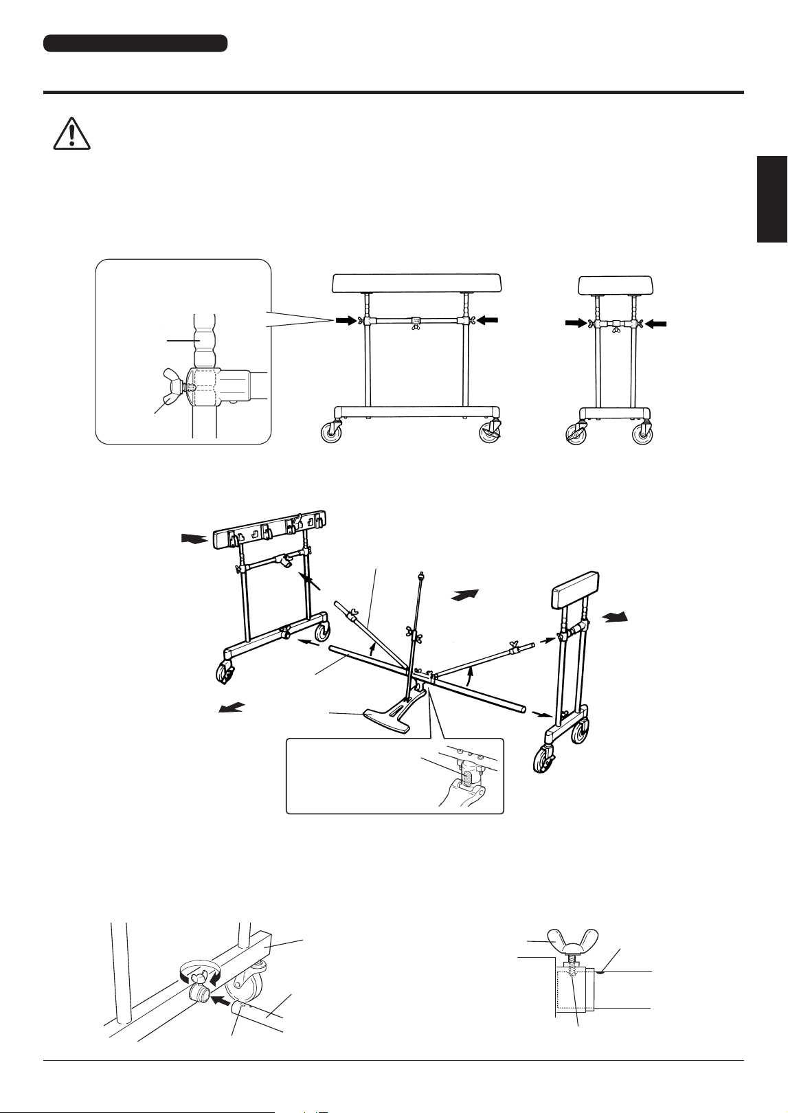
• Never touch the areas shown below when adjusting the
height. Doing so can result in pinched hands. Be sure to
hold the side frame when making height adjustments.
• Tighten bolts securely after determining the desired height.
Using the instrument with loose bolts could result in the
instrument collapsing, noisy operation, or other problems.
Tighten the bolts periodically.
Do not touch these
areas when adjusting
the height.
Side Frame
DMI-7
2/2
NOTICE
To avoid the possibility of damage to the product, follow the notices below.
● Do Not Use Outdoors
Avoid using the instrument outdoors. Avoid exposure to rain
or moisture.
● Handling
• Do not use hard orchestra bell mallets or other hard ob-
jects on your vibes. The resulting dents or scratches in the
tone bars could impair the sound.
• Rough handling of the controller and/or the driver could
cause damage to the internal circuitry.
● Moving and Transporting the Instrument
• Move the instrument carefully to avoid any impact. Before
moving the instrument, make sure that the AC adapter is
disconnected and the caster brakes are released. In ad-
dition, be sure to lift the instrument slightly when moving
over rough surfaces.
• When the instrument must be transported to a different
location, be sure to fully disassemble it, taking care to
pack each component properly. Disassembly steps are in
the reverse order of assembly.
● Maintenance
The tone bars should be polished from time to time using
a soft and dry cloth or silicone cloth. Stains that cannot be
removed with a dry cloth may be wiped off using a small
amount of ethyl alcohol. Never use thinner or benzene or a
wet cloth for cleaning purposes.
● Keep This Manual for Future Reference
After reading, keep this manual in a safe place.
● Assembly Cautions
• When assembling or disassembling the instrument, follow
the procedure outlined in this manual. Assembly in the
wrong order may impair the performance and functionality
of the instrument or result in noisy operation.
• Make sure to adjust the wire clip positions after assembly.
YV-4110(M) YV-3910(M) YV-3710(M) page 19)
•
Height adjustment of the striking surface (YV-4110(M)
YV-3910(M) YV-3710(M): page 19; YV-2700(G): page 25)
should be performed by AT LEAST 2 PERSONS.
• After final adjustment of the legs, the fixing screws must
be tightened securely to prevent loosening. Looseness
may cause the instrument to shift during performance and
could also result in noisy operation and other problems.
Retighten the screws periodically.
8 •
YV-4110(M) YV-3910(M) YV-3710(M) YV-2700(G)
Owner's Manual
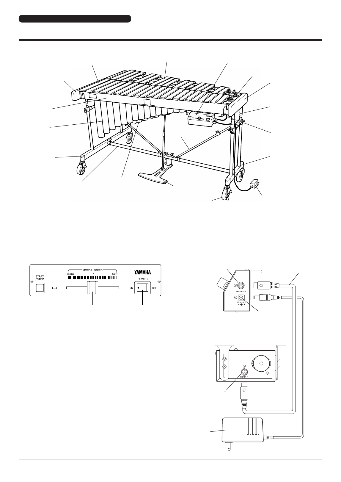
y
i
t
u
o
Nomenclature
re wq
* The illustration shows model YV-3710.
Pedal Stay
Rail No. 1
Large End
Resonators
(Natural Tone Side)
Large Leg
Natural Tone Bars
Accidental Tone Bars
Controller
Fan Belt
Small End
Pedal
Caster
AC Adapter
Small Leg
Driver
Slide Leg
Resonators
(Accidental Tone
Side)
Slant Shaft
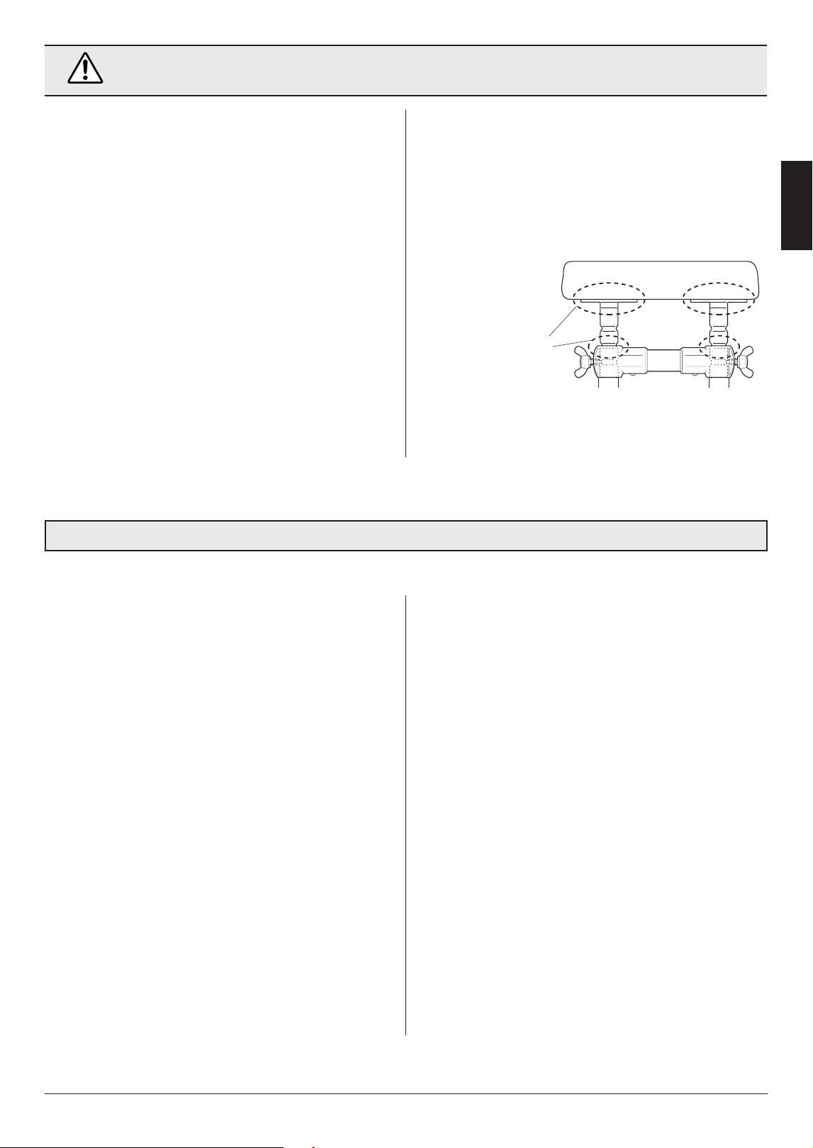
■ Vibes Drive Unit
YV-4110(M) YV-3910(M) YV-3710(M) YV-2700(G)
● Controller (Player Side)
1
POWER Switch
Turns the power on and off.
2
MOTOR SPEED Slider
Controls the fan rotation speed.
3
LED Indicator
Lights when the power is turned on and
flashes while the fan is rotating.
4
START/STOP Button
Starts and stops fan rotation.
5
DC 12-15V IN Jack
6
MOTOR OUT Terminal
7
MOTOR IN Terminal
8
8P DIN Cable
9
AC Adapter
● Controller (Right Side)
● Driver (Player Side)
YV-4110(M) YV-3910(M) YV-3710(M) YV-2700(G)
Owner's Manual
• 9
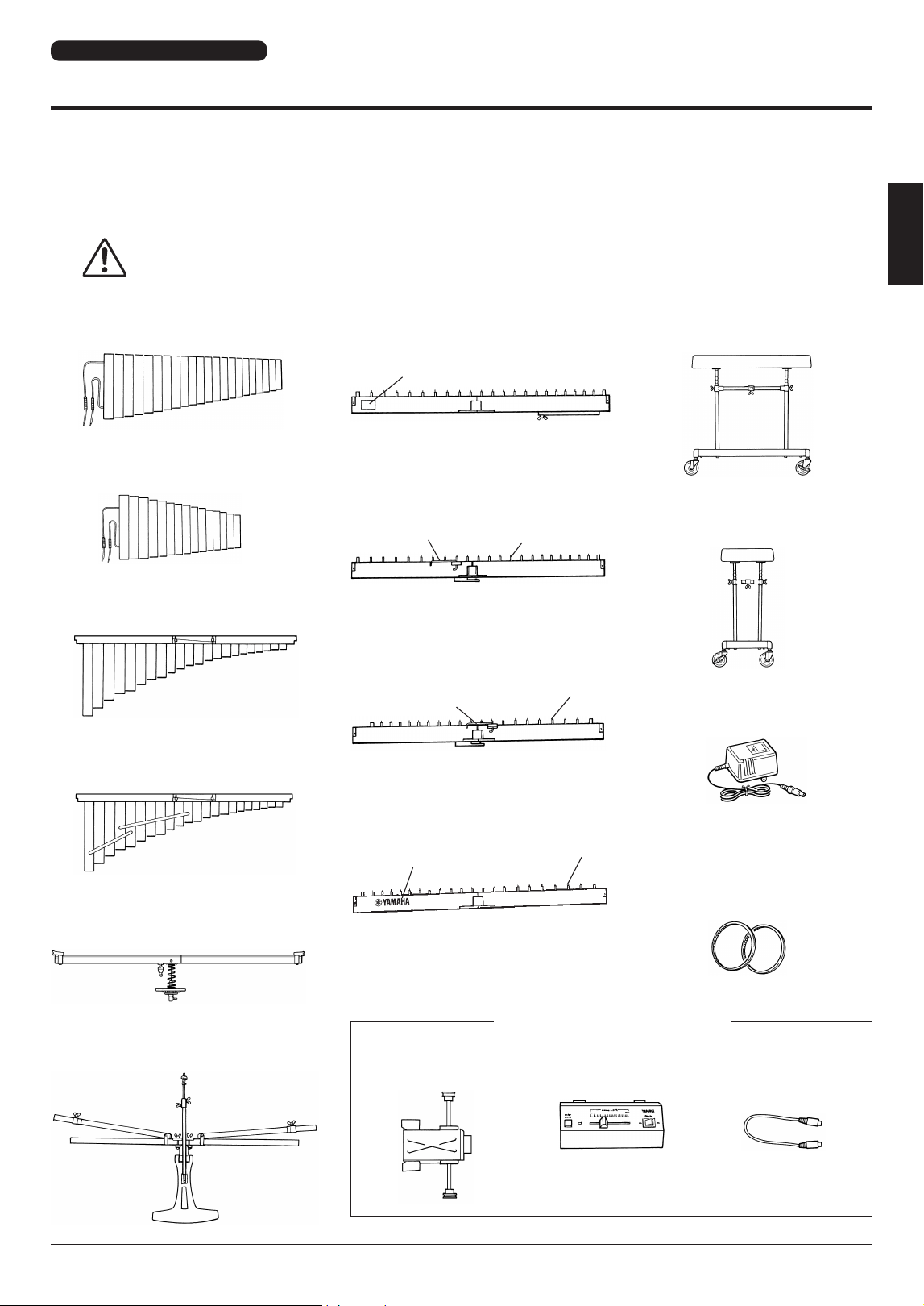
YV-4110(M) YV-3910(M) YV-3710(M)
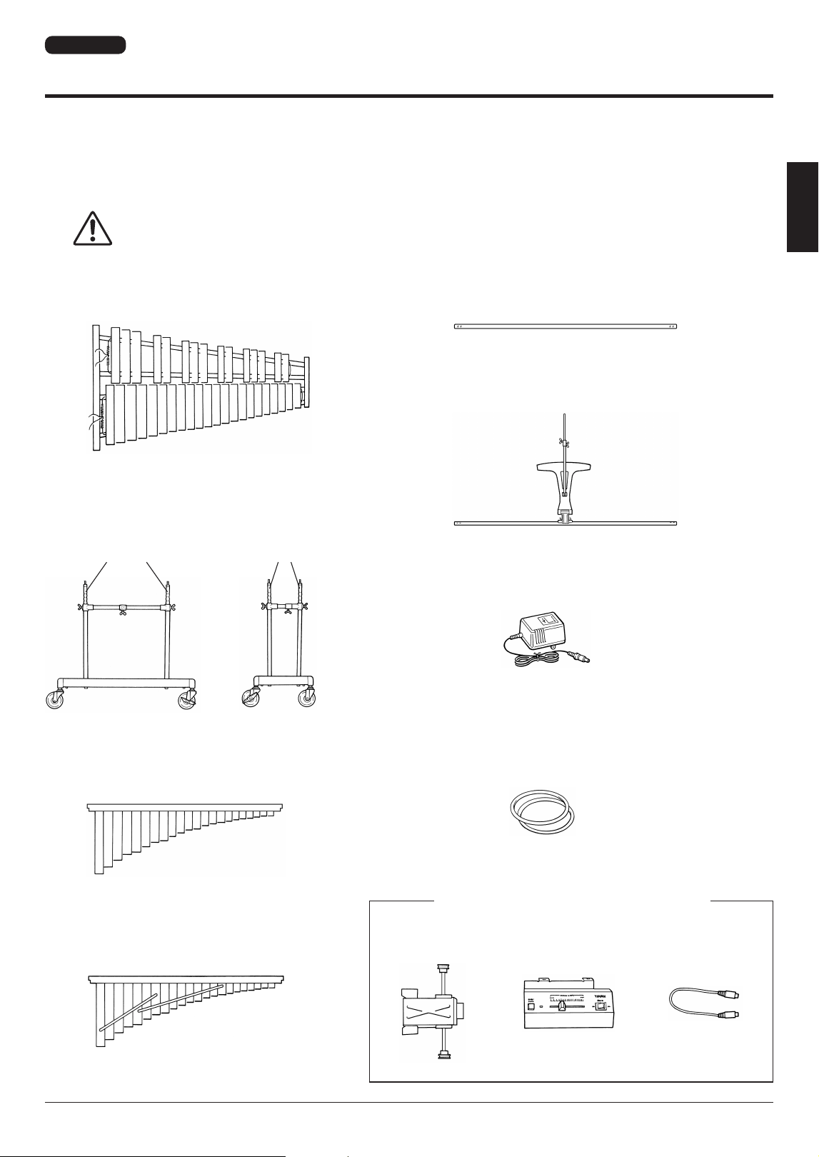
Package Contents
The shipping carton for your vibraphone should contain the parts shown below.
* The rails and resonators in the packages are folded.
Before assembling the instrument, confirm that all listed parts are included.
* In the event that a part is missing, please contact the shop where the instrument was purchased.
CAUTION
• Be careful not to get your fingers caught when opening the rail and resonator packages.
1
Natural Tone Bars x 1
2
Accidental Tone Bars x 1
3
Resonators (Natural Tone Side) x 1
4
Resonators (Accidental Tone Side) x 1
m
AC Adapter x 1
n
Synchro Belt (Fan Belt) x 2
p
Controller x 1
q
8P DIN Cable x 1
o
Driver x 1
k
Large
Leg x 1
l
Small Leg x 1
7
Rail (1) : Player Side x 1
8
Rail (2) : Player Side x 1
9
Rail (3) : Audience Side x 1
j
Rail (4) : Audience Side x 1
6
Pedal Stay x 1
5
Sustain Damper x 1
* May not be included depending on your
particular area.
Vibes Drive Unit: YVM-300
Name Plate
Rail Clamp
Posts (Larger number
than parts
o
and
!0
)
Rail Clamp
Posts
Logo Mark
Posts
10 •
YV-4110(M) YV-3910(M) YV-3710(M) YV-2700(G)
Owner's Manual
Package Contents
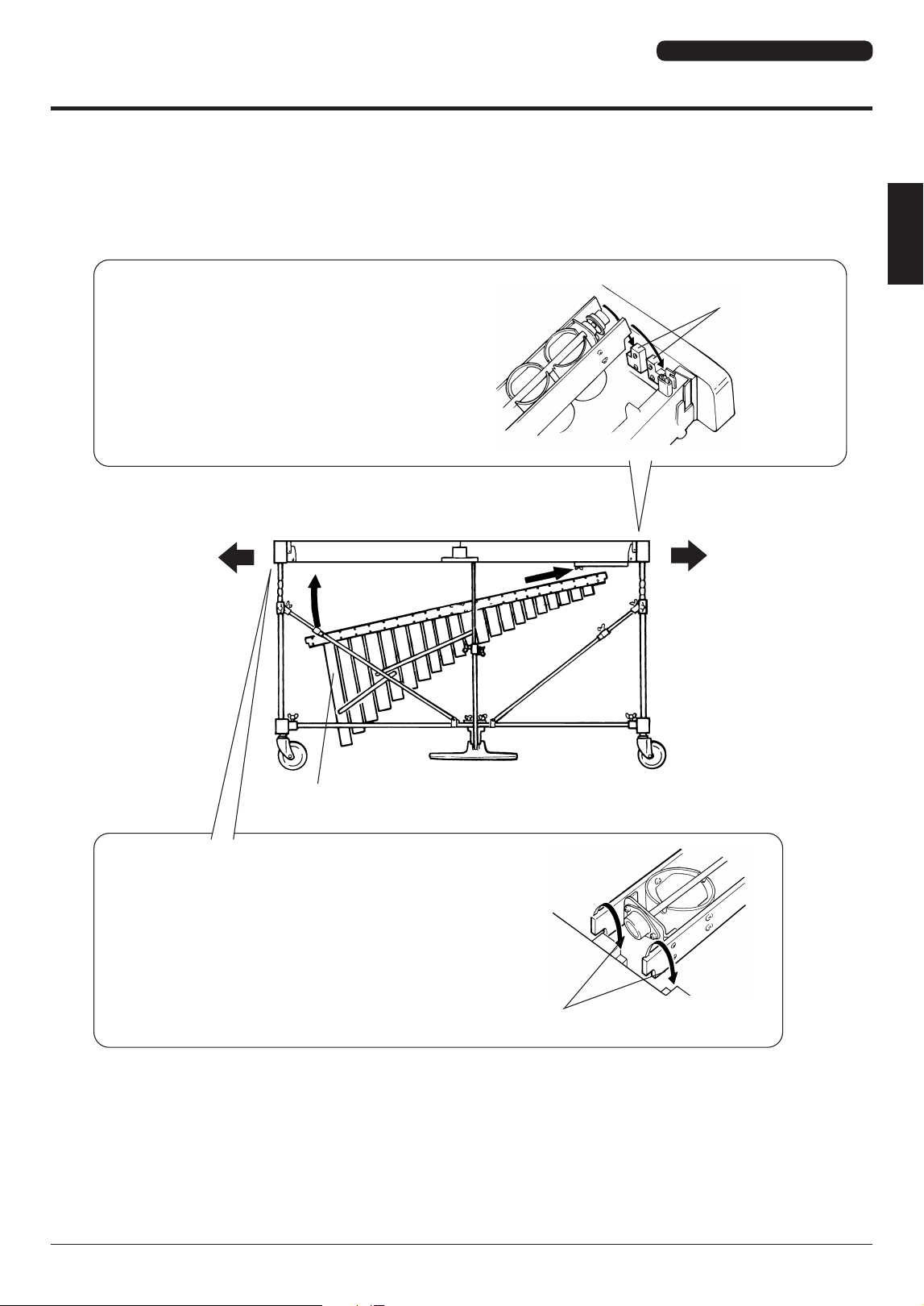
■ Dividable Parts and Collapsible Parts
The larger parts of the YV-4110(M) YV-3910(M) YV-3710(M) are designed to be either collapsible or easy to di-
vide into smaller components. When the instrument is broken down, its compact size makes it easy to transport
and storage requires a minimum amount of space.
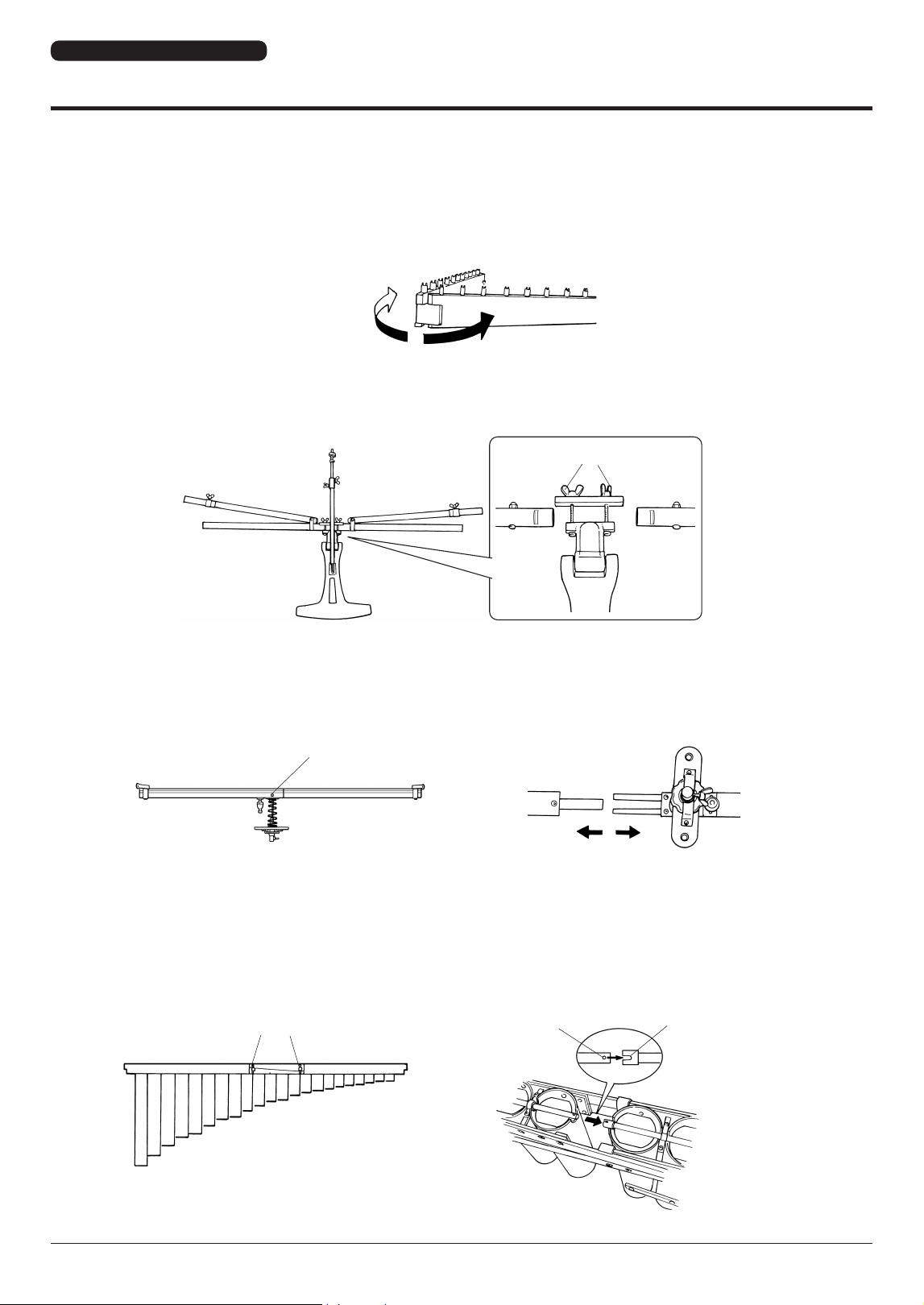
● Rails
The rails fold in from the center.
● Pedal Stay
The pedal stay divides into left and right sections, plus the pedal itself.
Loosen the two wing nuts and remove the stays from the pedal attachment.
● Sustain Damper
The sustain damper divides into two sections.
Loosen the bolt and separate the left and right sections.
● Resonators
Both resonators divide into two sections.
Loosen both bolts and separate the left and right sections.
* When assembling the resonators, make sure that the pin and notch are properly aligned.
Loosen
Loosen
Loosen
Pin
Notch
YV-4110(M) YV-3910(M) YV-3710(M)
YV-4110(M) YV-3910(M) YV-3710(M) YV-2700(G)
Owner's Manual
• 11
Assembly
CAUTION
• For safety, assembly should be performed by two or more people in a place that provides sufficient space.
• Be careful not to pinch your fingers when assembling the instrument. In particular, when assembling the
rails and resonators, two people should work together while checking each step carefully.
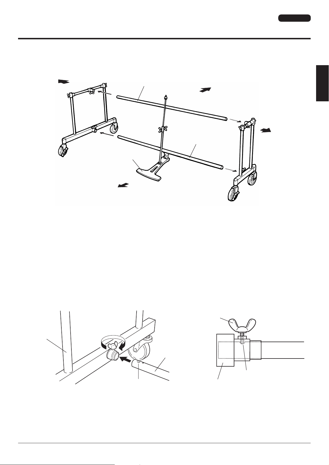
1
Connect the large and the small leg using the reinforcement stay and pedal stay.
* Before proceeding, make sure that the slide leg fixing bolts of the large and small leg are securely fastened.
1-2
Insert the pedal stay with its notch facing up into the lower joint of the large leg as far as it will go (aligning the notch with
the fixing bolt) and tighten the fixing bolt securely.
* The hole next to the notch serves as a reference for the correct insertion position.
1-3
Connect the other ends of the pedal stay with the small leg in the same way.
1-1
Place the large leg, small leg, and pedal stay so that after assembly each part will be positioned as illustrated.
Bass Side
Player Side
Audience Side
Treble Side
Large Leg
Slant Shaft
Pedal Stay
Pedal
Small Leg
Align the flat surfaces with
each other.
These flat surfaces should
face the player side.
Tighten
Large Leg
Pedal Stay
Notch
Fixing Bolt
Large Leg
Reference Hole
Pedal Stay
Notch
The tip of each slide leg fixing
bolt must be tightly seated in
one of the slide leg notches.
Slide Leg
Fixing Bolt
Large Leg
Slide Leg
Fixing Bolt
Small Leg
Slide Leg
Fixing Bolt
Slide Leg
Fixing Bolt
Slide Leg
YV-4110(M) YV-3910(M) YV-3710(M)
12 •
YV-4110(M) YV-3910(M) YV-3710(M) YV-2700(G)
Owner's Manual
Assembly
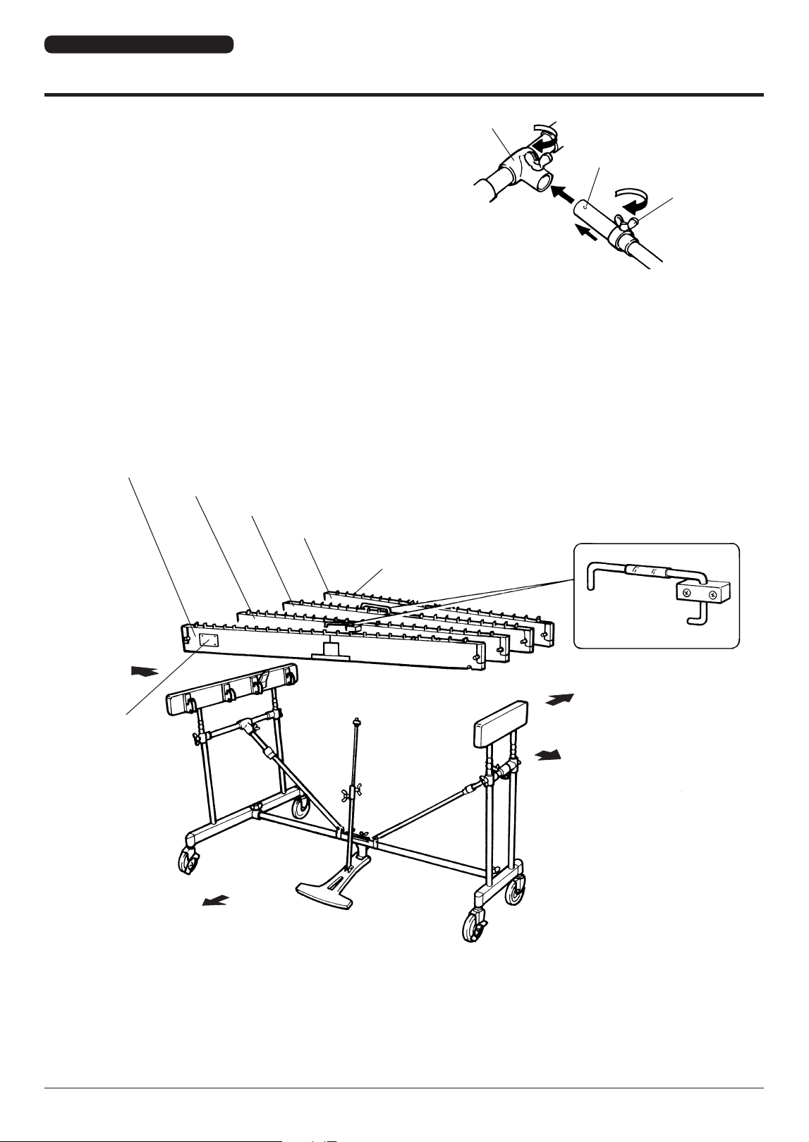
2
Insert rails (1) through (4) into the legs.
2-1
First, insert rail (2).
* Do not insert the rail entirely one side at a time, but at first alternately push in the left and right sides little by little, after which
the rail can be pushed down until it stops.
2-2
Next, securely insert rails (3), (1) and (4), in this order.
1-4
Loosen the slant shaft bolt, extend the shaft and insert
the shaft end into the leg joint. With the notch aligned with
the fixing bolt (the same as in the pedal stay assembly)
tighten the fixing bolt securely.
1-5
Connect the other side slant shaft with the small leg in the
same way.
Notch
Leg Joint
Slant Shaft
Bolt
Rail (1): This rail has a name plate. The name plate side should face the player.
Rail (2): This rail has a rail clamp and more posts than rail (3) or (4). The clamp side should face the player.
Rail (3): This rail has a rail clamp and fewer posts than rail (2). The clamp side should face the audience.
Rail (4): This rail has a Yamaha logo. Logo side should face the audience.
Post
Rail Clamp
Bass Side
Name Plate
Player Side
Audience Side
Treble Side
* The illustration shows model YV-3710.
YV-4110(M) YV-3910(M) YV-3710(M)

YV-4110(M) YV-3910(M) YV-3710(M) YV-2700(G)
Owner's Manual
• 13
Assembly
3
Attach the sustain damper.
3-1
1
Turn the fixing bolt (damper arm axle) of the damper arm attachment counterclockwise until the axle has fully disap-
peared in the attachment hole.
2
Align the damper arm hole with the damper arm axle.
3
Turn the fixing bolt of the damper arm attachment clockwise to insert the damper arm axle into the sustain damper
arm.
Damper Arm Attachment
Sustain Damper Arm
Sustain Damper
Sustain Damper Arm
Damper Arm Attachment
Damper Arm Axle
Sustain Damper Arm
Turn fixing bolt to
retract the axle.
Damper Arm Axle
Fixing Bolt
Sustain Damper Arm
Screw in to insert damper arm axle
1 2 3
YV-4110(M) YV-3910(M) YV-3710(M)
14 •
YV-4110(M) YV-3910(M) YV-3710(M) YV-2700(G)
Owner's Manual
Assembly
Rod Connector
2
Turn (screw on)
Lock Nut
3
Secure
Center Rod
Knurled Part
1
Loosen
1
Loosen
Center Rod Fixing Bolt
Pedal Rod
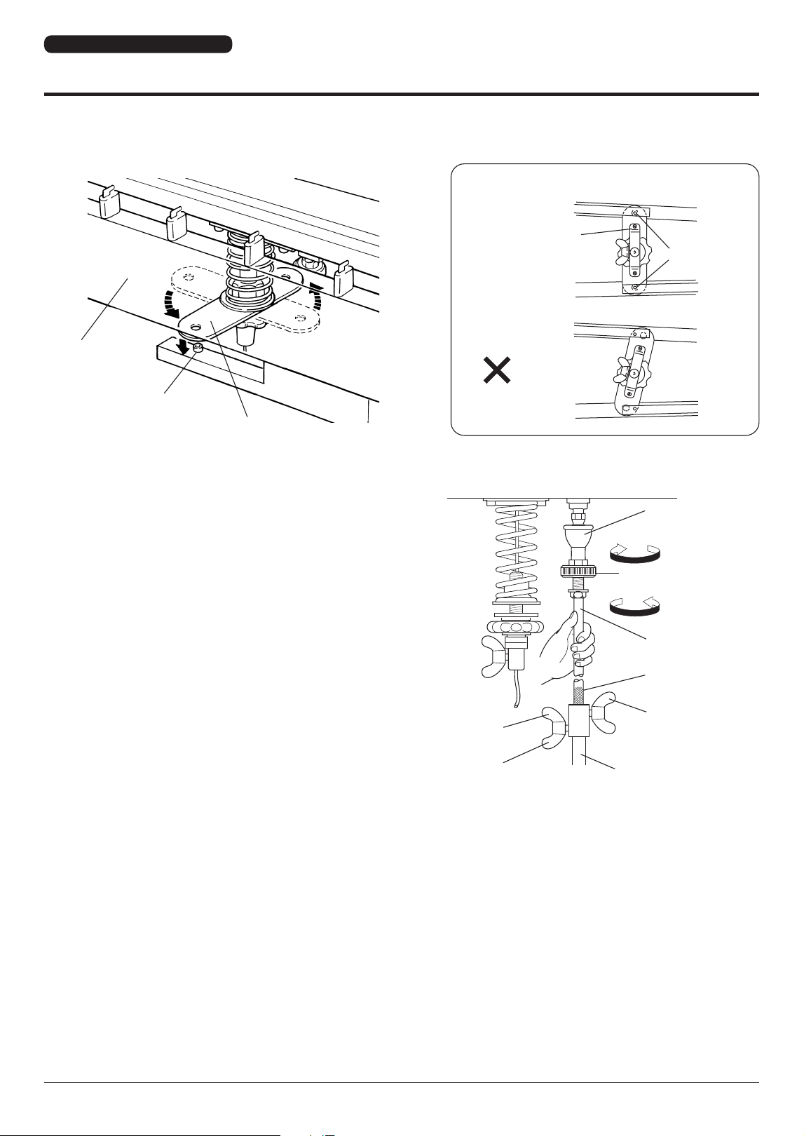
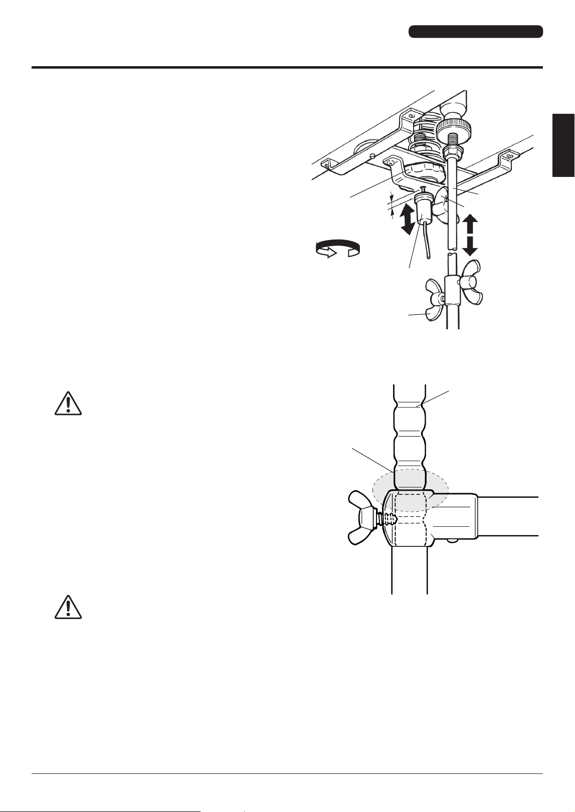
3-2
Align the holes in both ends of the damper spring stopper with the protrusions of the fittings on the bottom surfaces of rails
(2) and (3) and insert the protrusions into the holes.
3-3
1
Loosen the center rod fixing bolts to extend the center
rod.
2
Connect the center rod with the fitting of the rod con-
nector by firmly holding the center rod while turning
the rod connector.
3
Tighten the rod connector until it stops, and then
secure it with the lock nut.
Rail (2)
Protrusion
Damper Spring Stopper
Bottom View
OK
Damper
Spring Stopper
Protrusion
YV-4110(M) YV-3910(M) YV-3710(M)
YV-4110(M) YV-3910(M) YV-3710(M) YV-2700(G)
Owner's Manual
• 15
Assembly
4-1
4-1
First, place the small end onto the corresponding
resonator holders.
Resonator Holders
Resonator Holders
4
Attach the resonators.
Insert the resonators from underneath the frame. First, rest the small end and then the large end onto the resonator holders
(rubber).
NOTICE
• Be careful not to confuse the natural tone side and accidental tone side resonators.
• Be careful not to bump the resonators against the legs, etc.
4-2
To engage the large end, lift it over the resonator
holders and then insert it into the gap between
the two holders, as shown in the illustration.
Bass Side
Treble Side
Accidental Tone Side Resonators
4-2
YV-4110(M) YV-3910(M) YV-3710(M)
16 •
YV-4110(M) YV-3910(M) YV-3710(M) YV-2700(G)
Owner's Manual
Assembly
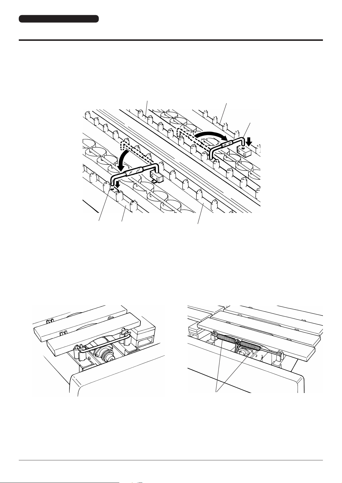
5
Set the tone bars.
5-1
(Refer to the illustration of step
3-3
)
Raise the pedal until the knurled part is fully retracted, and fix the center rod by tightening the center rod fixing bolt.
5-2
Engage the rail clamp on rail (2) and rail (3) with rail (1) and rail (4), respectively.
Rail (3)
Rail (4)
Rail Clamp
Rail Clamp
Rail (1)
Rail (2)
5-3
Hold the pedal depressed to keep the sustain damper lowered, and then carefully set the tone bars.
Align each tone bar individually, and hook its string onto the corresponding post.
Confirm that all strings are secured to their posts, and then hook the two springs at the large end into each other.
Treble Side
Springs
Bass Side
YV-4110(M) YV-3910(M) YV-3710(M)
YV-4110(M) YV-3910(M) YV-3710(M) YV-2700(G)
Owner's Manual
• 17
Assembly
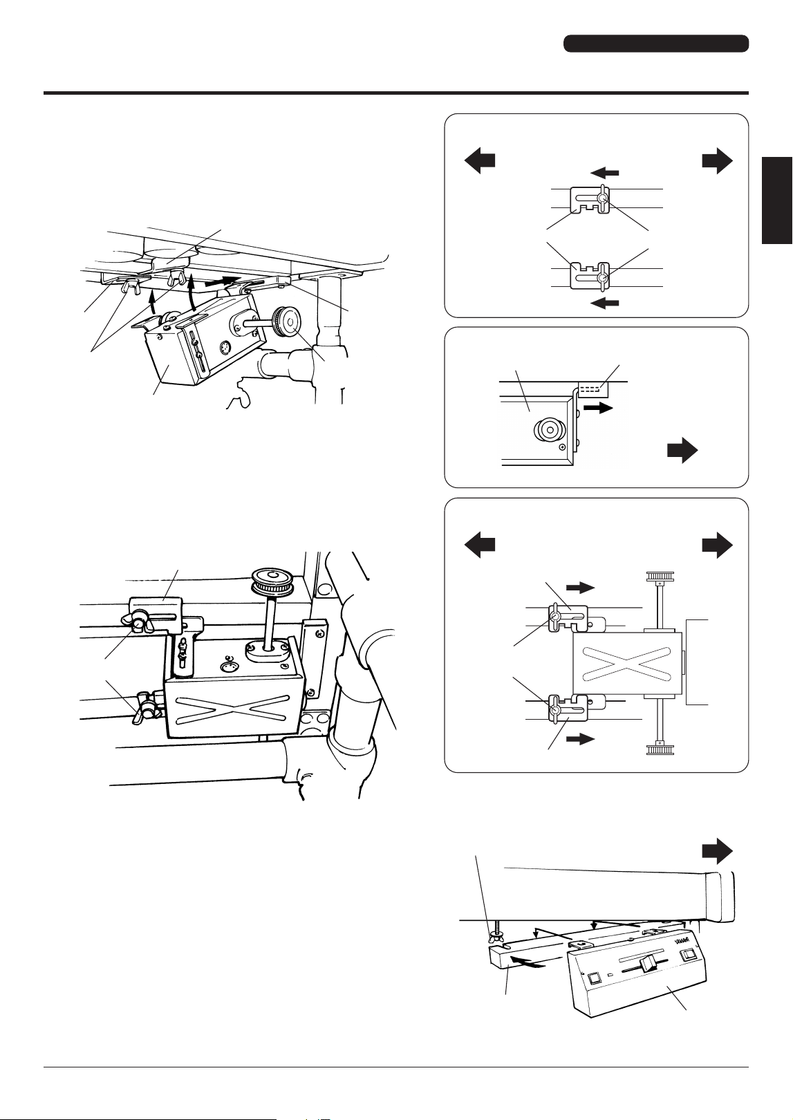
6
Attach the driver.
6-1
Loosen the fixing bolts at the bottom of rails (2) and (3) on
the small end, and slide both fittings in the direction of the
large end.
6-2
Fully insert the driver mount into the support fitting.
6-3
Slide the fittings moved in step
6-1
back in the direction of
the small end. Engage the two side mounts on the driver
securely with the fittings, and then tighten the fixing bolts
to fasten the driver.
* Set the driver so that the pulleys on either side are posi-
tioned directly below the fan side pulleys.
Fitting
Fixing Bolts
6-1
Rail (2)
Slide the fittings.
Rail (3)
Loosen the fixing
bolts.
Bottom View
Bass Side Treble Side
6-2
Support Fitting
Insert mount until it stops.
Side View
Driver
Treble Side
Fittng
Fixing Bolts
Motor Unit
Support
Fitting
Pulley
Fittng
6-3
Bottom View
Bass Side
Treble Side
Fitting
Tighten
fixing bolts.
Fitting
7
Attach the controller.
Loosen the fixing bolt, slide out the controller hanger and
hang the controller on the hanger. Return the controller
hanger to its proper position and tighten the fixing bolt.
Treble Side
Fixing Bolt
Controller Hanger
Controller
YV-4110(M) YV-3910(M) YV-3710(M)
18 •
YV-4110(M) YV-3910(M) YV-3710(M) YV-2700(G)
Owner's Manual
Assembly
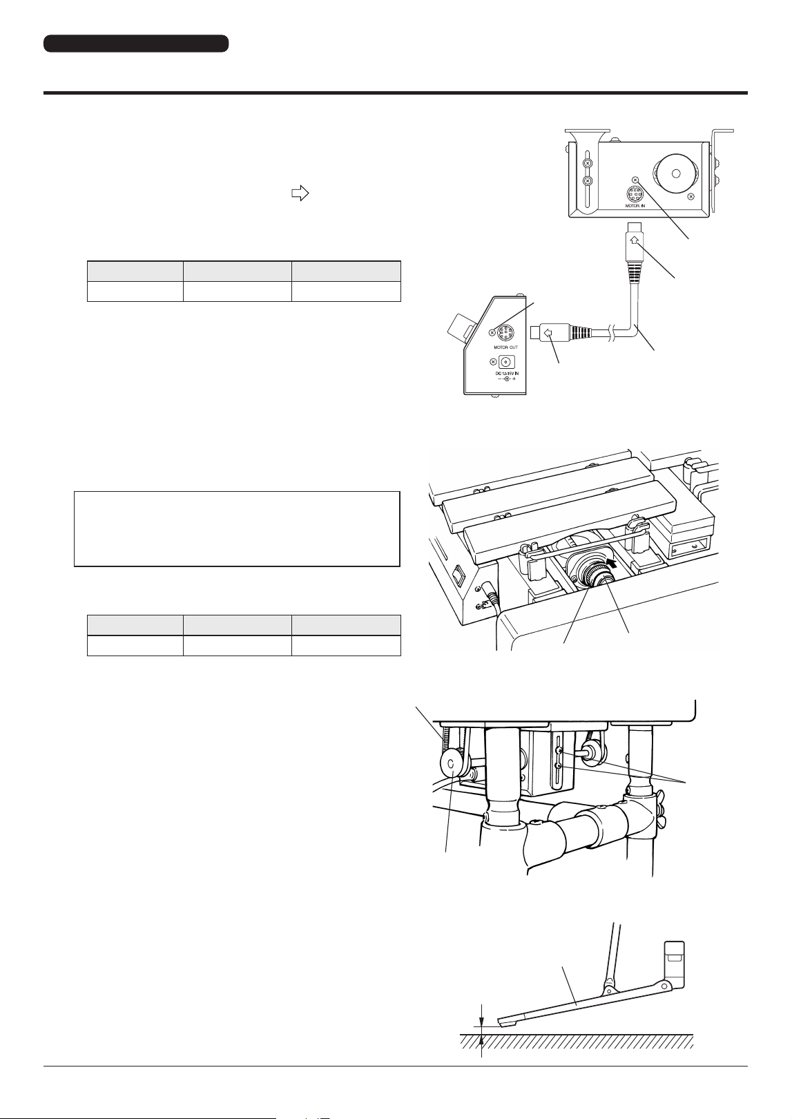
8
Connect the driver with the controller.
Connect the MOTOR IN terminal of the driver with the
MOTOR OUT terminal of the controller using the supplied
8P DIN cable*.
To connect them, align the arrow mark (
) on the plug
with the screw next to the jack.
* In case the 8P DIN cable is misplaced, the following spare
part may be ordered:
Part No. Part Name Specification
W5172200 8P DIN Cable L=220
Pedal
9/16" – 13/16"
(1.5 – 2 cm)
Floor
Driver
Screw
Arrow Mark
8P DIN Cable
Controller
Arrow Mark
Screw
Driver Side
Synchro Belt (Fan Belt)
Pulley
Driver
Positioning
Screws
Fan Side
Pulley
Synchro Belt (Fan Belt)
* Slide belt over the pulley.
9
Set the synchro belts (fan belts).
First, wrap the synchro belt around the driver pulley and
then carefully slide it over the fan side pulley.
If the belt cannot be mounted because the distance between
the pulleys is too wide, or the belt slips due to a pulley distance
that is too narrow, loosen the two driver positioning screws (see
illustration at right) to adjust the pulley distance (belt tension).
Tighten the screws securely after adjustment.
* In case the belt is misplaced or worn, the following spare
part may be ordered:
Part No. Part Name Specification
W5128092 Synchro Belt 18OTN15-3.0
10
ADJUSTMENTS
10-1
Pedal Stroke Adjustment
Loosen the center rod fixing bolts to adjust the protruding
length of the center rod to the desired pedal stroke, and
retighten the bolts. The recommended stroke (distance
between pedal and floor) is 9/16" to 13/16" (1.5 to 2 cm).
YV-4110(M) YV-3910(M) YV-3710(M)
YV-4110(M) YV-3910(M) YV-3710(M) YV-2700(G)
Owner's Manual
• 19
Assembly
10-2
Wire Clip Adjustment
To facilitate packing the unit for shipping, the wire clip is
initially set at a low position. For normal use this clip should
be adjusted as follows: With the pedal released, loosen the
fixing bolt of the wire clip, shift the clip up until distance A
in the illustration at right is 1/16" to 1/8" (1 to 3 mm), and
tighten the fixing bolt in this position.
The clip also allows you to set the instrument to “half sustain
damper” (slight continuous damper effect) or “open damper”*
by changing its position accordingly.
* To set to “open damper,” depress the damper pedal fully to
keep the damper open, and set the wire clip to the highest
position to lock the damper.
10-3
Damper Spring Adjustment
The damper effect (its pressing force on the tone bars)
and the pedal force can be increased by turning the spring
adjustment wheel counterclockwise.
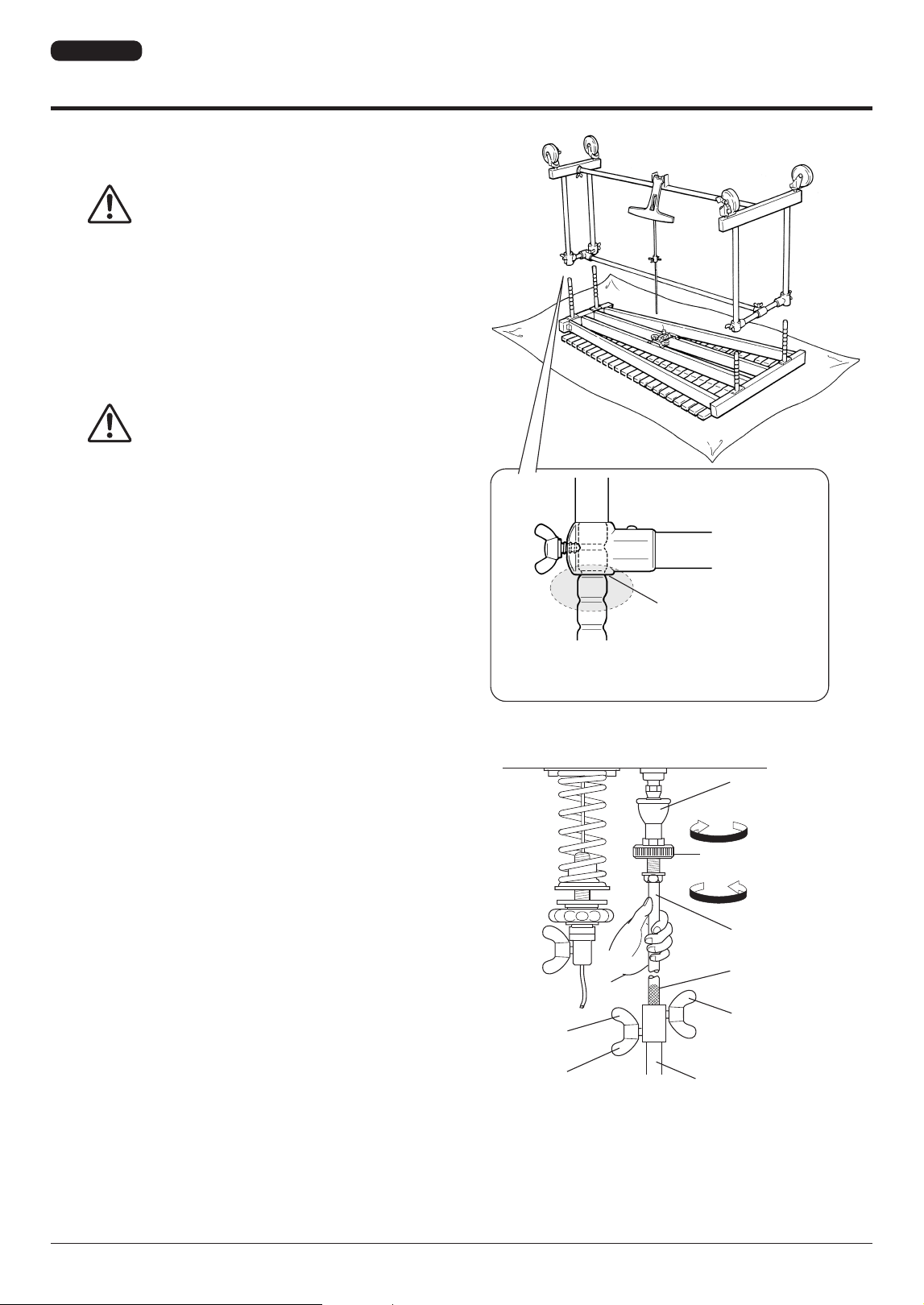
10-4
Tone Bar Height Adjustment
CAUTION
• When adjusting the tone bar height, be
sure to have two people supporting the
frame, one at each end using both hands.
To adjust the height of the tone bars, first remove the
synchro belt, driver, controller, tone bars, and resonators in
reverse order following steps 9, 8, 7, 6, 5, and 4, and loosen
the center rod fixing bolts.
Loosen the slide leg fixing bolts on the small and large legs,
while supporting the frame ends by hand.
Lift the frame ends to the desired height and then securely
tighten each fixing bolt, aligning it with the corresponding
notch on the slide leg. Bolt and notch are aligned when the
next higher notch is flush with the upper leg flange.
* The fourth notch from top corresponds to the standard
height setting.
CAUTION
• Do not touch the slide legs during
adjustment. Otherwise, your fingers may
get caught and be injured.
• If you tighten the bolts at any location
other than at the notches, the slide legs
may slip, which can be dangerous.
Upon completion of assembly, check to make sure that each
bolt is tightened securely.
Slide Leg
Align notch with
upper flange.
A
10-3
Spring
Adjustment
Wheel
Strong
Wire Clip
Center Rod
Fixing Bolt
Center Rod
10-1
Pedal Stroke
Adjustment
Wire Clip Fixing Bolt
10-2
YV-4110(M) YV-3910(M) YV-3710(M)
20 •
YV-4110(M) YV-3910(M) YV-3710(M) YV-2700(G)
Owner's Manual
Before Playing
■ Power Supply
Prepare the supplied AC adapter.
CAUTION
• Be sure to use the supplied AC adapter. Using a different adapter may cause
damage not covered by the warranty.
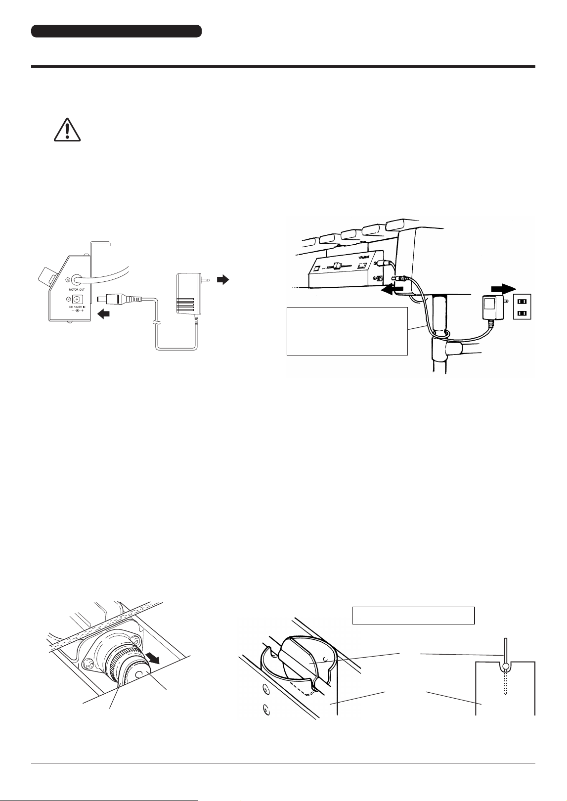
1
Connect the small plug of the AC adapter to the DC 12-15V IN jack on the controller.
2
Plug the AC adapter into a power outlet.
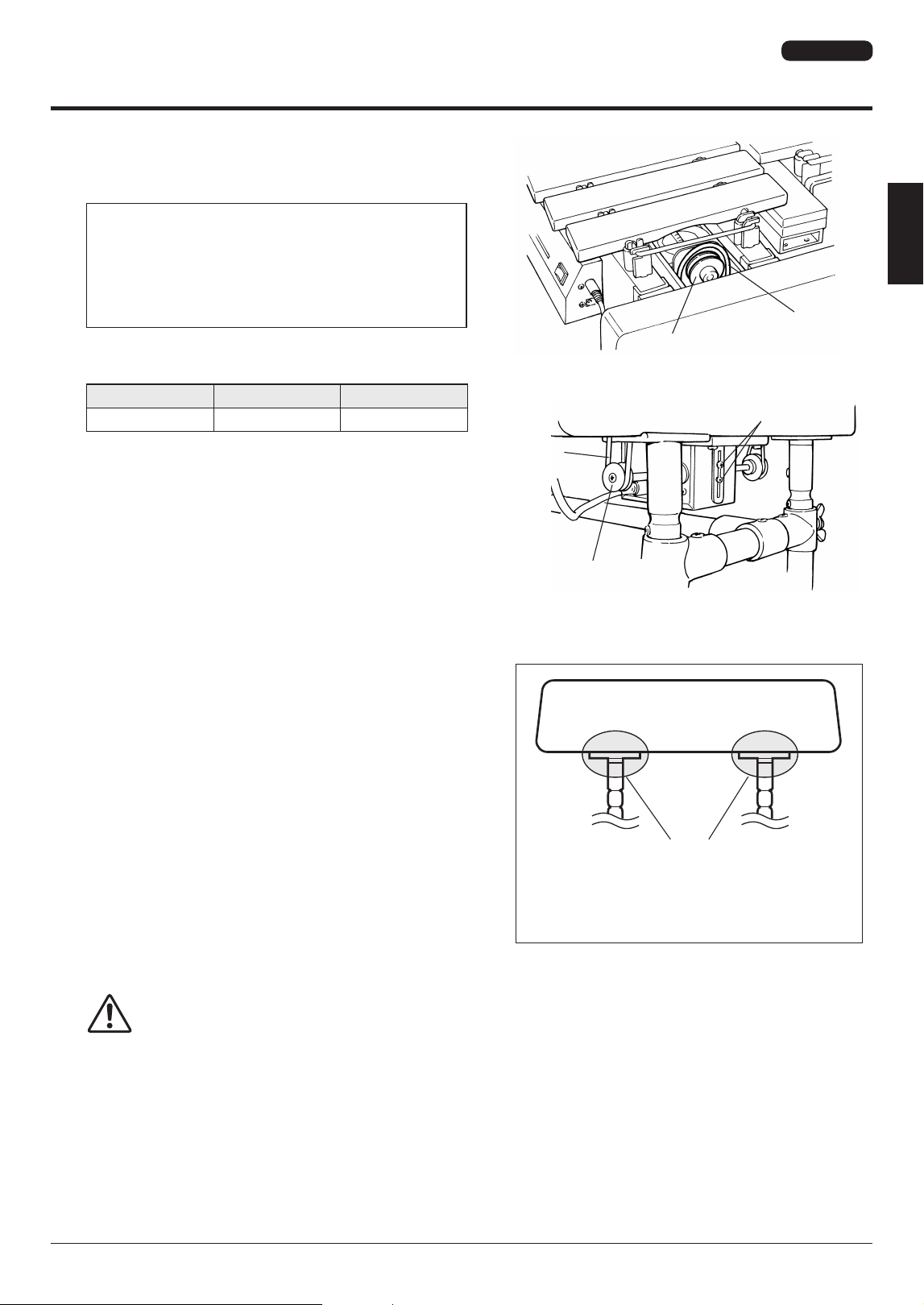
■ Pause Memory Function Setting (YV-4110(M) YV-3910(M) YV-3710(M) only)
The YV-4110(M), YV-3910(M), and YV-3710(M) are equipped with a PAUSE MEMORY FUNCTION that stops the
fan always in exactly the same position as when it was turned off (no vibrato applied).
After connecting to an AC outlet, set the PAUSE MEMORY to the desired fan stop position as follows:
1
Turn the controller power ON.
2
Press the START/STOP button once to start the fan, and then press the START/STOP button again to
stop the fan.
3
Remove the synchro belt by sliding it off the fan side pulley, as shown in the illustration. Position the
fan vertically (fan position with strongest resonator effect) and remount the belt.
Perform this setting for both the natural and the accidental tone side.
Controller
DC 12-15V IN
AC Adapter
AC
* Wrapping the AC adapter cord
once around one of the legs will
prevent accidental disconnection
of the adapter plug.
Slide belt off.
Fan Side Pulley
Synchro Belt
Set the fan to a vertical position.
Resonator
Fan
YV-4110(M) YV-3910(M) YV-3710(M) YV-2700(G)
YV-4110(M) YV-3910(M) YV-3710(M) YV-2700(G)
Owner's Manual
• 21
Slide Legs
Slide Legs
Package Contents
2
Large Leg x 1
3
Small Leg x 1
4
Resonators (Natural Tone Side) x 1
5
Resonators (Accidental Tone Side) x 1
6
Reinforcement Stay x 1
7
Pedal Stay x 1
8
AC Adapter x 1
May not be included depending on your particular area.
9
Round Belt (Fan Belt) x 2
Vibes Drive Unit: YVM-200 YVM-100
j
Driver x 1
k
Controller x 1
l
8P DIN Cable x 1
The shipping carton for your vibraphone should contain the parts shown below.
* The rails and resonators in the packages are folded.
Before assembling the instrument, confirm that all listed parts are included.
* In the event that a part is missing, please contact the shop where the instrument was purchased.
CAUTION
• Be careful not to get your fingers caught when opening the rail and resonator packages.
1
Vibes Main Unit x 1
YV-2700(G)
22 •
YV-4110(M) YV-3910(M) YV-3710(M) YV-2700(G)
Owner's Manual
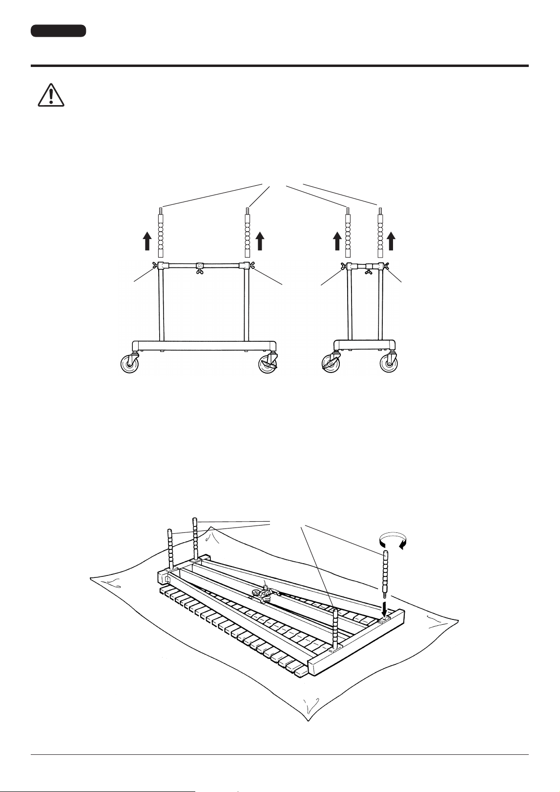
2
Place the main unit bottom side up on the floor.
3
Screw each slide leg into the screw hole on the bottom side of the main unit. (All four slide legs are
identical.)
Assembly
CAUTION
• For safety, assembly should be performed by two or more people in a place that provides sufficient space.
• Be careful not to pinch your fingers when assembling the instrument. In particular, when assembling the
rails and resonators, two people must work together while checking each step carefully.
1
Loosen the slide leg fixing bolts of the large and the small leg, and remove the four slide legs.
Slide Legs
Tighten
Slide Legs
Slide Leg Fixing Bolt
Slide Leg Fixing Bolt
Slide Leg Fixing Bolt
Large Leg Small Leg
* The illustrations show model YV-2700.
YV-2700(G)
YV-4110(M) YV-3910(M) YV-3710(M) YV-2700(G)
Owner's Manual
• 23
Assembly
4
Place the large leg, small leg, pedal stay and reinforcement stay so that after assembly each part will
be positioned as illustrated.
5
Connect the large leg and small leg with the pedal stay and the reinforcement stay.
Insert the pedal stay with its notch facing up into the lower joint of the large leg as far as it will go
(aligning the notch with the fixing bolt) and tighten the fixing bolt securely.
* The hole next to the notch serves as a reference for the correct insertion position.
6
In the same way, insert the reinforcement stay with its notch facing down into the upper joint of the
large leg and tighten the fixing bolt.
7
Connect the other ends of both stays with the small leg in the same way.
Large Leg
Tighten
Notch
Pedal Stay
Fixing Bolt
Large Leg
Notch
Pedal Stay
Bass Side
Large Leg
Reinforcement Stay
Audience Side
Pedal Stay
Pedal
Player Side
Small Leg
Treble Side
YV-2700(G)
24 •
YV-4110(M) YV-3910(M) YV-3710(M) YV-2700(G)
Owner's Manual
Assembly
8
Connect the slide legs with the small and large
legs.
CAUTION
• When adjusting the tone bar height, be
sure to have two people supporting the
frame, one at each end using both hands.
Align the legs from above so that the slide legs slide into the
corresponding leg holes. Adjust to the desired height and
then securely tighten each slide leg fixing bolt, aligning it
with the corresponding notch of the slide leg. Fixing bolt and
notch are aligned when the next lower notch is flush with the
upper leg flange.
CAUTION
• Do not touch the slide legs during
adjustment. Otherwise, your fingers may
get caught and be injured.
• If you tighten the bolts at any location
other than at the notches, the slide legs
may slip, which can be dangerous.
Align notch with
upper flange.
* The fourth notch from the tone bar side corresponds
to the standard height setting.
Treble
Side
Bass
Side
Rod Connector
2
Turn (screw on)
Lock Nut
3
Secure
Center Rod
Knurled Part
1
Loosen
1
Loosen
Center Rod Fixing Bolt
Pedal Rod
9
After fixing the legs, connect the pedal with the
sustain damper.
1
Loosen the center rod fixing bolts to extend the center
rod.
2
Connect the center rod with the fitting of the rod con-
nector by firmly holding the center rod while turning
the rod connector.
3
Tighten the rod connector until it stops, and then
secure it with the lock nut.
10
Stand up the vibes, and attach the resonators.
(Refer to YV-4110(M) YV-3910(M) YV-3710(M) assembly
step 4 on page 15.)
11
Mount the driver and the controller, and connect
them using the supplied 8P DIN cable.
(Refer to YV-4110(M) YV-3910(M) YV-3710(M) assembly
steps 6 through 8 on pages 17 and 18.)
YV-2700(G)
YV-4110(M) YV-3910(M) YV-3710(M) YV-2700(G)
Owner's Manual
• 25
Assembly
12
Attach the round belt (fan belt).
Slip the round belt (fan belt) over the fan side pulley first,
and then pull it over the flange of the driver pulley.
If the belt cannot be mounted because the distance be-
tween the pulleys is too wide, or the belt slips due to a
pulley distance that is too narrow, loosen the two driver
positioning screws (see illustration at right) to adjust
the pulley distance (belt tension). Tighten the screws
securely after adjustment.
* If the belt is misplaced or worn, the following spare part may
be ordered:
Part No. Part Name Specification
W5128041 Fan Belt 3ØL275
13
Adjust the pedal stroke.
(Refer to YV-4110(M) YV-3910(M) YV-3710(M) assembly
step 10-1 on page 18.)
14
After assembly, confirm that each bolt and screw
is tightened securely.
15
Height adjustment should always be performed
by at least two persons.
To adjust the height of the tone bars, first remove the round
belt (fan belt), driver, controller and tone bars*, and loosen
the center rod fixing bolts.
(* To remove the tone bars, disengage the springs on the
large end, and then unhook the string from the post.)
Support both frame ends by hand (do not touch the metal
parts shown in the illustration), and loosen the slide leg fix-
ing bolts.
Lift the frame ends to the desired height and then securely
tighten each slide leg fixing bolt, aligning it with the cor-
responding notch of the slide leg. Bolt and notch are aligned
when the next higher notch is flush with the upper leg flange.
(Refer to step 8 on page 24.)
CAUTION
• Do not touch the slide legs during adjustment. Otherwise, your fingers may get caught and be injured.
• If you tighten the bolts at any location other than at the notches, the slide legs may slip, which can be
dangerous.
16
This completes the assembly of the instrument.
To play, connect the supplied AC adapter to the DC 12-15V IN jack of the controller. (Refer to YV-4110(M) YV-3910(M) YV-3710(M)
assembly procedure, “Power Supply”, on page 20.)
Upon completion of assembly, check to make sure that each bolt is tightened securely.
Frame
Do not touch !
For height adjustment, make sure to support the
instrument by the wooden frame. Do not touch the
metal parts.
Fan Side
Pulley
Round Belt
(Fan Belt)
Driver Side
Driver Positioning Screws
Round Belt
(Fan Belt)
Pulley
YV-2700(G)
26 •
YV-4110(M) YV-3910(M) YV-3710(M) YV-2700(G)
Owner's Manual
■ YV-4110(M)
●
Range: c–c4, 4 Octaves
●
Bars: Aluminum Alloy, graduating from 39–57 mm (1-1/2"
to 2-1/4") wide, 13 mm (1/2") thick, YV-4110: Glossy Gold
Finish, YV-4110M: Matte Gold Finish
●
Pitch: A = 442 Hz
●
Drive Unit: YVM-300 (Pause-Memory Controller), 25–145 rpm
●
Power Supply: Yamaha AC Adapter PA-130 (D.C. 12V, 1A
North America), PA-D015 (D.C. 15V, 1A Europe), or
other adapter recommended by Yamaha.
●
Power Consumption: 2.9 W (PA-130), 3.6 W (PA-D015)
●
Dimensions (Length x Width): 185 x 83 cm (72-7/8" x 32-5/8")
●
Height Adjustment: 86–94 cm (33-7/8" to 37")
●
Weight: 65 kg (143-1/4 lbs)
●
Oversized Casters: 100 mm (4") high
■ YV-3910(M)
●
Range: c–f3, 3-1/2 Octaves
●
Bars: Aluminum Alloy, graduating from 39–57 mm (1-1/2"
to 2-1/4") wide, 13 mm (1/2") thick, YV-3910: Glossy Gold
Finish, YV-3910M: Matte Gold Finish
●
Pitch: A = 442 Hz
●
Drive Unit: YVM-300 (Pause-Memory Controller), 25–145 rpm
●
Power Supply: Yamaha AC Adapter PA-130 (D.C. 12V, 1A
North America), PA-D015 (D.C. 15V, 1A Europe), or
other adapter recommended by Yamaha.
●
Power Consumption: 2.9 W (PA-130), 3.6 W (PA-D015)
●
Dimensions (Length x Width): 164 x 83 cm (64-5/8" x 32-5/8")
●
Height Adjustment: 86–94 cm (33-7/8" to 37")
●
Weight: 61 kg (134-1/2 lbs)
●
Oversized Casters: 100 mm (4") high
Specications
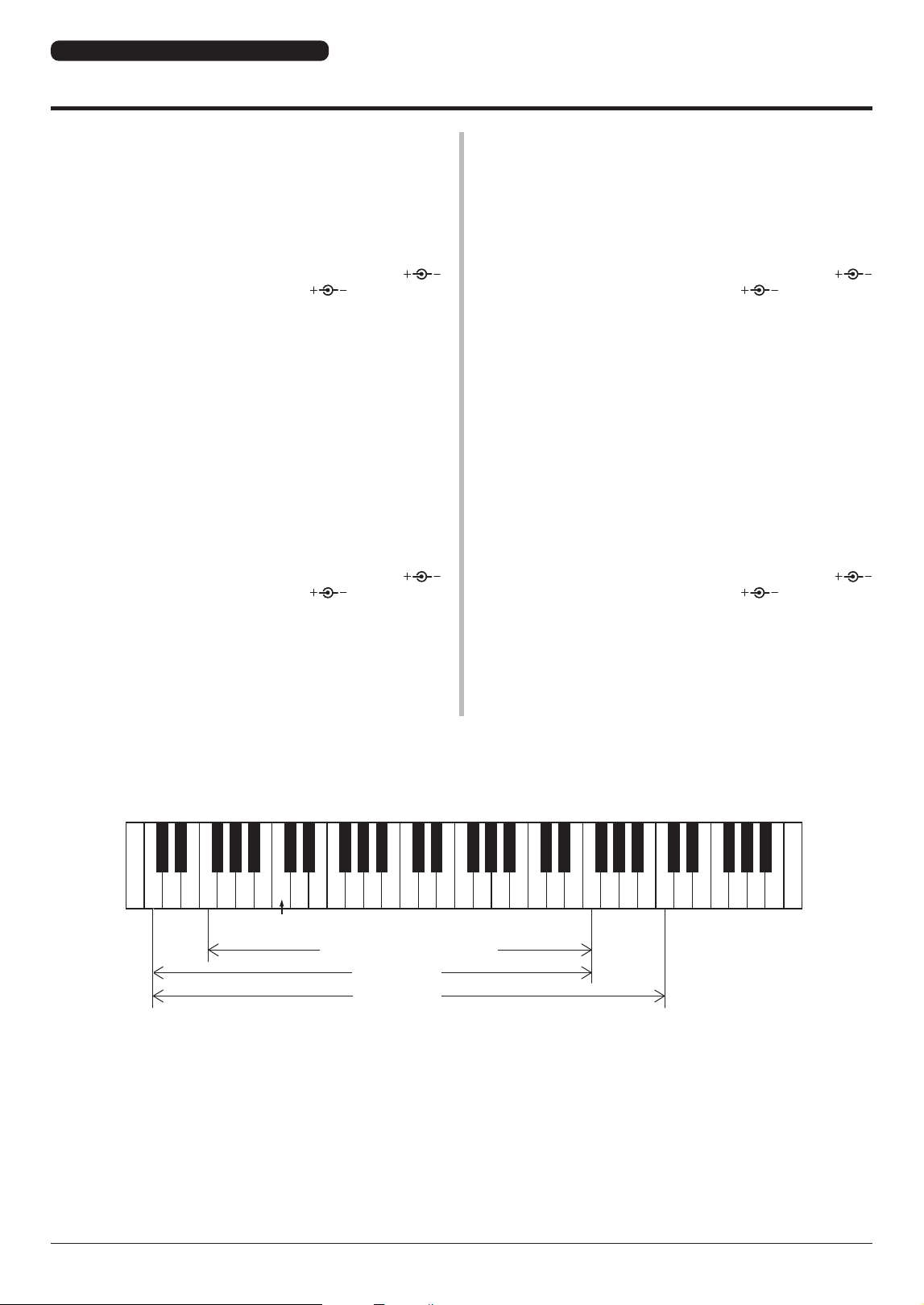
● SCALE RANGE
* The contents of this manual apply to the latest specifications as of the publishing date. To obtain the latest
manual, access the Yamaha website then download the manual file.
Since specifications, equipment or separately sold accessories may not be the same in every locale, please
check with your Yamaha dealer.
27 28 30 32
f
f3
c4c
33 35 37 39 40 42 44 45 47 49 51 52 54 56 57 59 61 63 64 66 68 69 71 73 75 76 78 80 81 83 85 87 88
YV-3710(M) YV-2700(G)
YV-3910(M)
YV-4110(M)
Middle C
■ YV-3710(M)
●
Range: f–f3, 3 Octaves
●
Bars: Aluminum Alloy, graduating from 39–57 mm (1-1/2"
to 2-1/4") wide, 13 mm (1/2") thick, YV-3710: Glossy Gold
Finish, YV-3710M: Matte Gold Finish
●
Pitch: A = 442 Hz
●
Drive Unit: YVM-300 (Pause-Memory Controller), 25–145 rpm
●
Power Supply: Yamaha AC Adapter PA-130 (D.C. 12V, 1A
North America), PA-D015 (D.C. 15V, 1A Europe), or
other adapter recommended by Yamaha.
●
Power Consumption: 2.9 W (PA-130), 3.6 W (PA-D015)
●
Dimensions (Length x Width): 143 x 82 cm (56-1/4" x 32-1/4")
●
Height Adjustment: 86–94 cm (33-7/8" to 37")
●
Weight: 58 kg (127-7/8 lbs)
●
Oversized Casters: 100 mm (4") high
■ YV-2700(G)
●
Range: f–f3, 3 Octaves
●
Bars: Aluminum Alloy, graduating from 39–57 mm (1-1/2" to
2-1/4") wide, 13 mm (1/2") thick, YV-2700: Silver Satin Finish,
YV-2700G: Glossy Gold Finish
●
Pitch: A = 442 Hz
●
Drive Unit: YVM-200 (Pause Controller), 25–145 rpm
●
Power Supply: Yamaha AC Adapter PA-130 (D.C. 12V, 1A
North America), PA-D015 (D.C. 15V, 1A Europe), or
other adapter recommended by Yamaha.
●
Power Consumption: 2.9 W (PA-130), 3.6 W (PA-D015)
●
Dimensions (Length x Width): 143 x 82 cm (56-1/4" x 32-1/4")
●
Height Adjustment: 81–89 cm (31-7/8" to 35")
●
Weight: 52 kg (114-5/8 lbs)
●
Oversized Casters: 100 mm (4") high
YV-4110(M) YV-3910(M) YV-3710(M) YV-2700(G)

©2014 Yamaha Corporation
Published 06/2024
2024 年 6 月发行
IPCP-U0
VHU7520
10-1 Nakazawa-cho, Chuo-ku, Hamamatsu, 430-8650 Japan
〒430-8650静岡県浜松市中央区中沢町 10-1