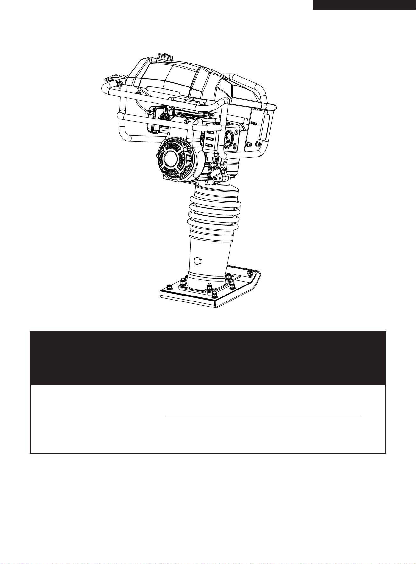
FOR YOUR SAFETY
READ AND UNDERSTAND THE ENTIRE MANUAL BEFORE OPERATING
MACHINE
Save This Manual for Future Reference
Upright Rammer
Operator’s Manual
MODEL NUMBER :
SERIAL NUMBER :
29350
Both model number and serial number may be found on the main label.
You should record both of them in a safe place for future use.
Original Instructions

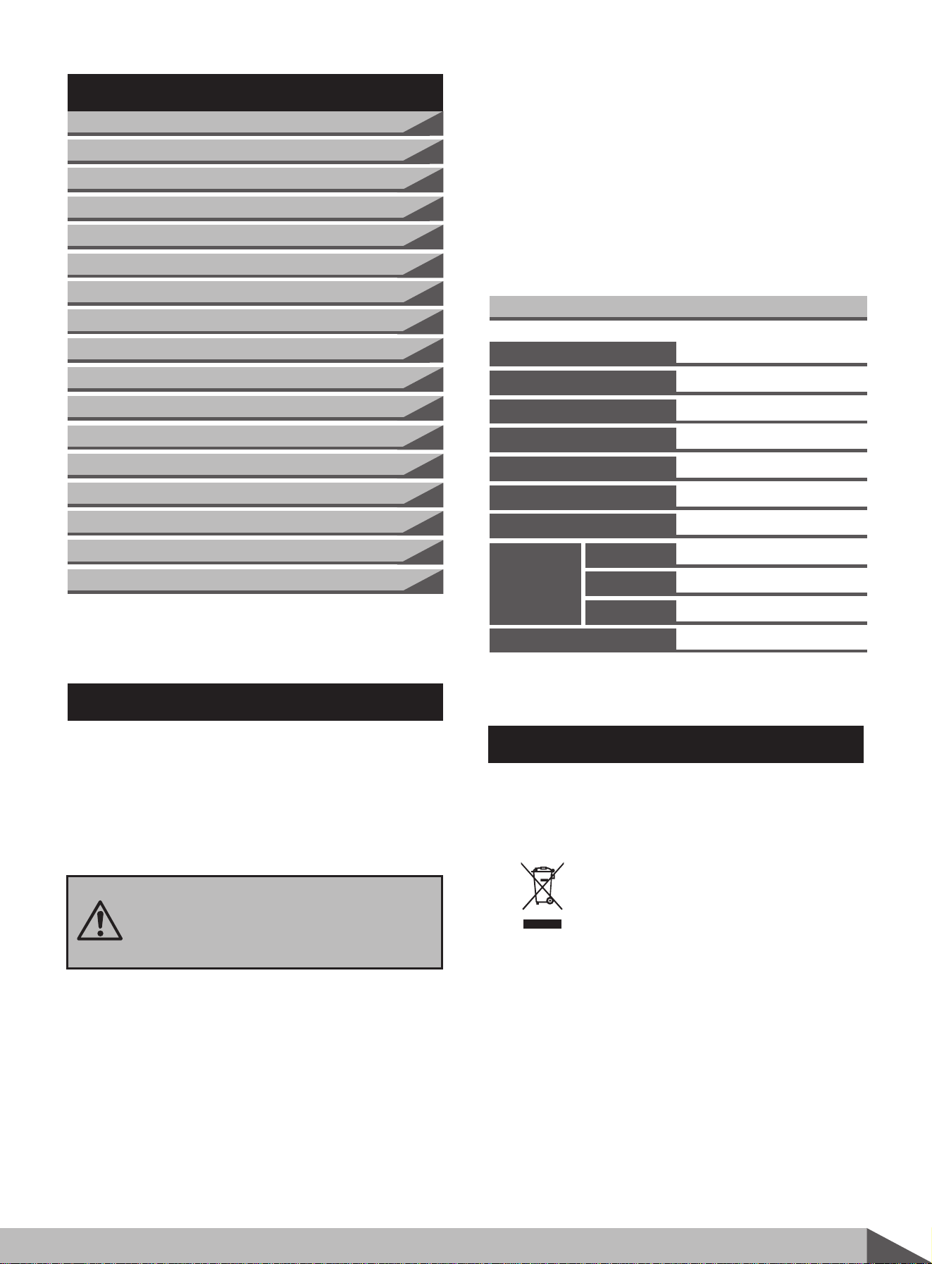
TABLE OF CONTENTS
INTRODUCTION
Your new Upright Rammer will more than satisfy
your expectations. It has been manufactured under
stringent quality standards to meet superior
performance criteria. You will find it easy and safe
to operate, and with proper care, it will give you
many years of dependable service.
Carefully read through this entire
operator’s manual before using your
new unit. Take special care to heed the
cautions and warnings.
The upright rammer is a powerful compacting tool
capable of applying a tremendous fore in
consecutive impacts to a soil surface. Its
applications include soil compacting for road,
embankments and reservoirs as well as backfilling
for gas pipelines, water pipelines and cable
installation work.
The impact force of this rammer levels and
uniformly compacts voids between soil particles
to increase dry density.
The Engine Manufacturer is responsible for all
engine-related issues with regards to performance,
power rating, specifications, warranty and service.
Please refer to the Engine Manufacturer’s
owner/operator’s manual, packed separately with
your unit, for more information.
3
Upright rammer
This marking indicates that this
product should not be disposed with
other household wastes. To prevent
possible harm to the environment
or human health from uncontrolled
waste disposal, recycle it responsibly
to promote the sustainable reuse of
material resources. To return your
used device, please use the return
and collection systems or check with
your local authority or local stores
for advice of environmental safe
recycling.
Specifications
29350
355mmx280mm
660-700
18500 N
60mm-70mm
11m/min-14m/min
149cc, 5.0HP, Gas
1010 mm
580 mm
715 mm
78.0 kg
Item No.
Ramming Shoe Size
Impact Blows / Minute
Impact Force / Blow
Impact Plate Stroke
Travel Speed
Engine
3
3
4
4
4
6
7
7
8
8
9
9
11
11
12
13
14
Introduction
Specifications
Symbols
Safety
General Safety Rules
Specific Safety Rules
Contents supplied
Assembly
Know your rammer
Features and Controls
Operation
Operating Instructions
Maintenance
Storage
Lifting/Transporting
Trouble Shooting
Parts Schedule
Overall
Size
Height
Width
Length
Operating Weight
RECYCLING AND DISPOSAL

SAFETY
Understand your machine
Read and understand the operator’s manual and
labels affixed to the machine. Learn its application
and limitations as well as the specific potential
hazards peculiar to it.
Be thoroughly familiar with the controls and their
proper operation. Know how to stop the machine
and disengage the controls quickly.
Make sure to read and understand all the
instructions and safety precautions as outlined in
the Engine Manual, packed separately with your
unit. Do not attempt to operate the machine until
you fully understand how to properly operate and
maintain the Engine and how to avoid accidental
injuries and/or property damage.
Work area
Never start or run the engine inside a closed area.
The exhaust fumes are dangerous, containing carbon
monoxide, an odorless and deadly gas. Operate this
unit only in a well ventilated outdoor area.
Never operate the machine without good visibility
or light.
Personal safety
Do not operate the machine while under the
influence of drugs, alcohol, or any medication that
could affect your ability to use it properly.
Dress properly. Wear heavy long pants, boots and
gloves. Do not wear loose clothing, short pants,
jewelry of any kind. Secure long hair so it is above
shoulder level. Keep your hair, clothing and gloves
away from moving parts. Loose clothes, jewelry
or long hair can be caught in moving parts.
Check your machine before starting it. Keep guards
in place and in working order. Make sure all nuts,
bolts, etc. are securely tightened.
4
Upright rammer
The rating plate on your machine may show
symbols. These represent important information
about the product or instructions on its use.
SYMBOLS
Use safety equipment. Always wear
eye and hearing protection, safety
footwear, gloves and helmets.
Read these instructions for use
carefully.
It is forbidden to remove or tamper
with the protection devices and
safety devices.
Keep feet away from the bottom.
Do not smoke or have open flames.
Keep children and bystanders off
and away.
Use extreme caution when storing,
handling and using fuels, as they are
highly volatile and explosive in vapor
state.
Do not touch parts which are hot
from operation. Serious burns may
result.
General Safety Rules
Don not pull the handrail over.
Keep children and bystanders away while operatinga
rammer. Distractions can cause you to losecontrol.

Never operate the machine when it is in need of
repair or is in poor mechanical condition. Replace
damaged, missing or failed parts before using it.
Check for fuel leaks. Keep the machine in safe
working condition.
Do not use the machine if the engine’s switch does
not turn it on or off. Any gasoline powered machine
that can not be controlled with the engine switch
is dangerous and must be replaced.
Form a habit of checking to see that keys and
adjusting wrenches are removed from machine
area before starting it. A wrench or a key that is
left attached to a rotating part of the machine may
result in personal injury.
Stay alert, watch what you are doing and use
common sense when operating the machine.
Do not overreach. Do not operate the machine
while barefoot or when wearing sandals or similar
lightweight footwear. Wear protective footwear
that will protect your feet and improve your footing
on slippery surfaces. Keep proper footing and
balance at all times. This enables better control of
the machine in unexpected situations.
Avoid accidental starting. Be sure the engine’s
switch is off before transporting the machine or
performing any maintenance or service on the
unit. Transporting or performing maintenance or
service on a machine with its switch on invites
accidents.
Fuel safety
Never store fuel or machine with fuel in the tank
inside a building where fumes may reach an spark,
open flame, or any other source of ignition, such
as a water heater, furnace, clothes dryer and the
like. Allow the engine to cool before storing in any
enclosure.
Fuel is highly flammable, and its vapors can explode
if ignited. Take precautions when using to reduce
the chance of serious personal injury.
When refilling or draining the fuel tank, use an
approved fuel storage container while in a clean,
well-ventilated outdoor area. Do not smoke, or
allow sparks, open flames or other sources of
ignition near the area while adding fuel or operating
the unit. Never fill fuel tank indoors.
Keep grounded conductive objects, such as tools,
away from exposed, live electrical parts and
connections to avoid sparking or arcing. These
events could ignite fumes or vapors.
Always stop the engine and allow it to cool before
filling the fuel tank. Never remove the cap of the
fuel tank or add fuel while the engine is running
or when the engine is hot. Do not operate the
machine with known leaks in the fuel system.
Loose the fuel tank cap slowly to relieve any
pressure in the tank.
Replace all fuel tank and container caps securely
and wipe up spilled fuel. Never operate the unit
without the fuel cap securely in place.
Avoid creating a source of ignition for spilled fuel.
If fuel is spilled, do not attempt to start the engine
but move the machine away from the area of
spillage and avoid creating any source of ignition
until fuel vapors have dissipated.
Store fuel in containers specifically designed and
approved for this purpose.
Store fuel in a cool, well-ventilated area, safely
away from sparks, open flames or other sources
of ignition.
Machine use and care
Never pick up or carry a machine while the engine
is running.
Do not force the machine. Use the correct machine
for your application. The correct machine will do
the job better and safer at the rate for which it
was designed.
Do not change the engine governor settings or
over-speed the engine. The governor controls the
maximum safe operating speed of the engine.
5
Upright rammer
Never overfill fuel tank (there should be no fuel
above the upper limit mark).
Replace all fuel tank and container caps securely
and wipe up spilled fuel. Never operate the unit
without the fuel cap securely in place.

Service
Keep the engine and muffler free of grass, leaves,
excessive grease or carbon build up to reduce the
chance of a fire hazard.
Never douse or squirt the unit with water or any
other liquid. Keep handles dry, clean and free from
debris. Clean after each use.
Observe proper disposal laws and regulations for
gas, oil, etc. to protect the environment.
Store idle machine out of the reach of children
and do not allow persons unfamiliar with the
machine or these instructions to operate it. Machine
is dangerous in the hands of untrained users.
Before cleaning, repair, inspecting, or adjusting,
shut off the engine and make certain all moving
parts have stopped. Always make sure the engine’s
switch is in its “OFF” position. Disconnect the spark
plug wire, and keep the wire away from the plug
to prevent accidental starting.
Have your machine serviced by a qualified repair
personnel using only identical replacement parts.
This will ensure that the safety of the machine
maintained.
Specific Safety Rules
Do not run the engine at a high speed when you
are not pounding.
Do not put hands or feet near rotating parts.
Avoid contact with hot fuel, oil, exhaust fumes and
hot surfaces. Do not touch the engine or muffler.
These parts get extremely hot from operation.
They remain hot for a short time after you turn off
the unit. Allow the engine to cool before doing
maintenance or making adjustments.
If the machine should start to make an unusual
noise or vibration, immediately shut off the engine,
disconnect the spark plug wire, and check for the
cause. Unusual noise or vibration is generally
warning of trouble.
Use only attachments and accessories approved
by the manufacturer. Failure to do so can result
in personal injury.
Maintain the machine. Check for misalignment or
binding of moving parts, breakage of parts and
any other condition that may affect the machine’s
operation. If damaged, have the machine repaired
before use. Many accidents are caused by poorly
maintained equipment.
6
Upright rammer
To avoid injury, keep hands, fingers and feet away
from the base plate. Grip the handle of the plate
upright rammer firmly with both hands. If both
hands are holding the handle and your feet are
clear of the upright rammer base, your hands,
fingers and feet can not be injured by the upright
rammer base.
Always operate the machine from behind, never
pass or stand in front of the machine when the
engine is running.
Never place tools or any other item under the
plate upright rammer.
If the unit strikes a foreign object, stop the engine,
disconnect the spark plug, thoroughly inspect the
machine for any damage, and repair the damage
Always ascend slopes carefully, in a direct path
and in reverse to present the upright rammer from
toppling over onto the operator.
Always park the unit on a firm and level surface
and shut the tool off.
To reduce exposure to vibration, limit the hours
of operation and take periodic breaks to minimize
repetition and rest your hand. Reduce the speed
and force in which you do the repetitive movement.
Try to fill each day with jobs where operating
hand-held power equipment is not required.
Do not overload the machine capacity by
compacting too deep in a single pass or at too
fast a rate.
Never operate the unit at high transport speeds
on hard or slippery surfaces.
Exercise extreme caution when operating on or
crossing roads. Stay alert for hidden hazards or
traffic. Do not carry passengers.
Never leave the operating position and leave the
upright rammer unattended when the engine is
running.
Always stop the engine when compacting is
delayed or when walking from one location to
another.
Stay away from the edged of ditches and avoid
actions that may cause the upright rammer to
topple over.
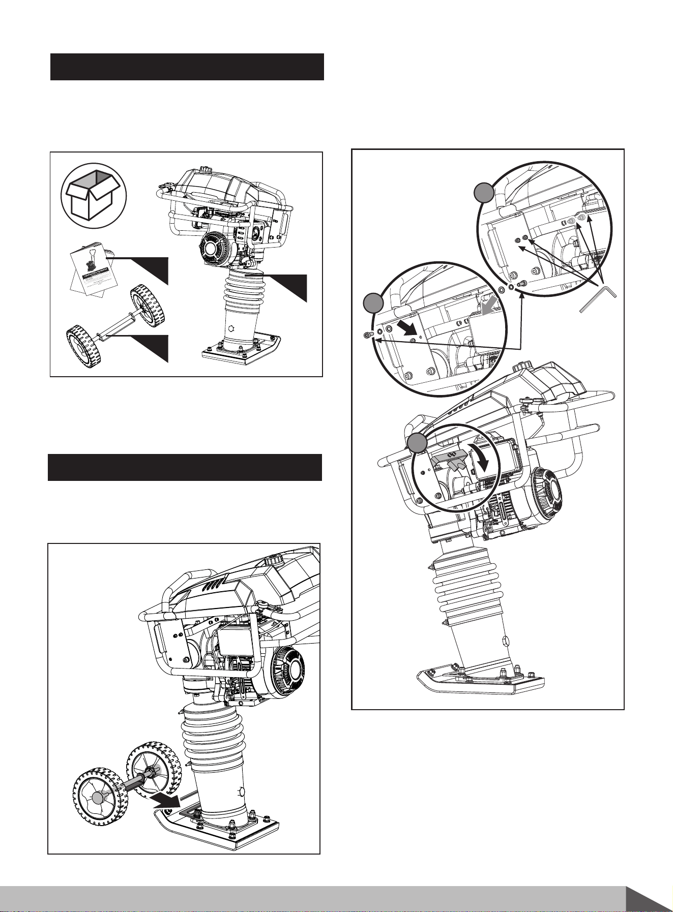
CONTENTS SUPPLIED
The
Upright Rammer
comes partially assembled
and is shipped in carefully packed carton. After all
the parts have been removed from the carton, you
should have:
7
Upright rammer
1. Upright Rammer Chassis with Engine
2. Operator’s Manual & Engine Manual
3. Wheels Kit (Optional)
1
2
Assembly
Following the assembly directions below , you will
assembly the upright rammer in a few minutes.
3
Insert the fixing plate of the wheels kit under the
support plate of machine.
ASSEMBLY
1
2
3
M6x16 (x2)
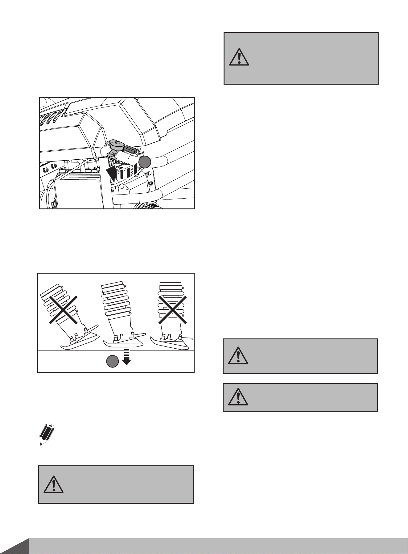
Push down the fixing plate, make sure the holes in
the fixing plate align with the holes in the handle
weldment. Secure each side using M6x16 screw,
spring washer and flat washer. Tighten the screws
and the ones behind them.
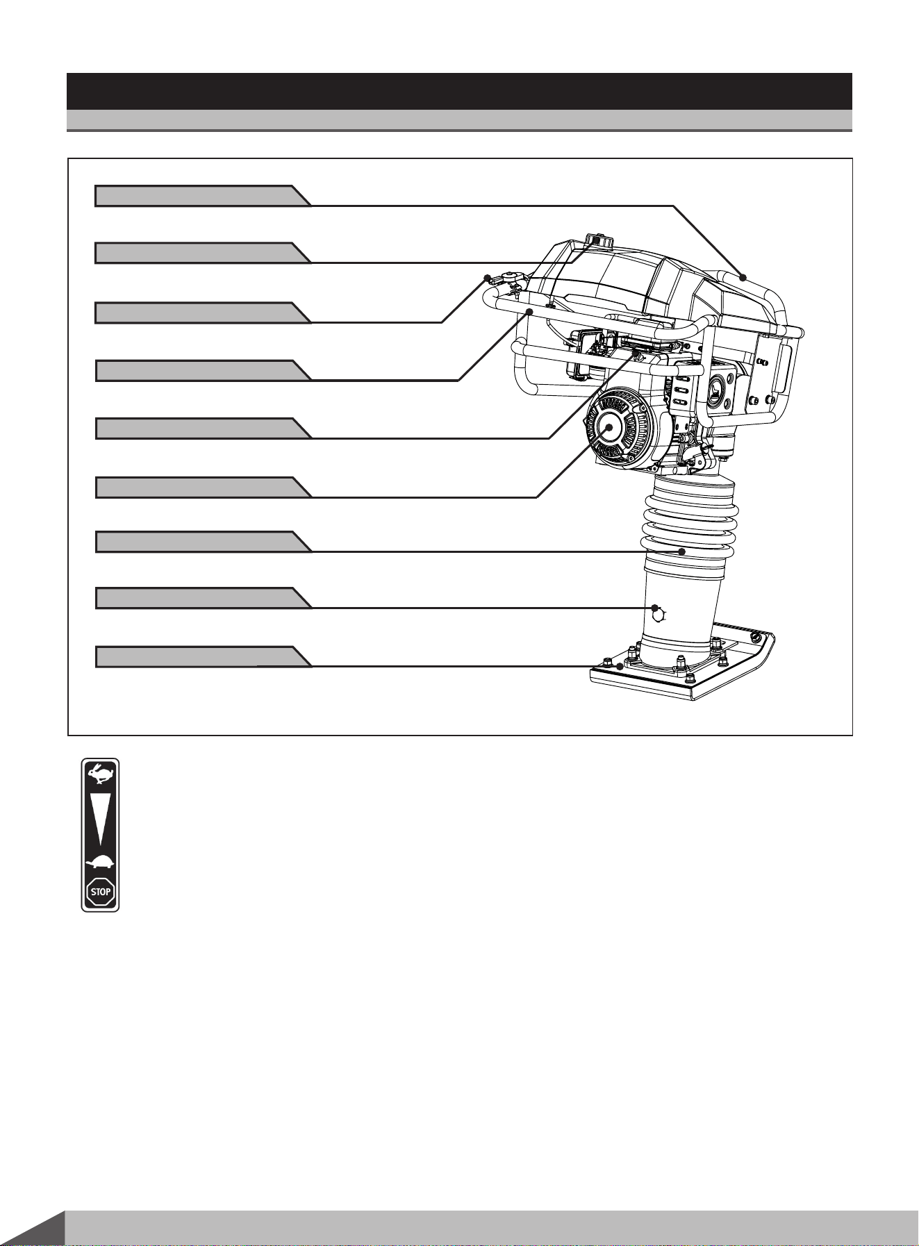
KNOW YOUR RAMMER
Features and Controls
8
Upright rammer
Throttle lever
Used to adjust engine speed (rpm). Move
lever forward (SLOW) to reduce engine
speed, move lever back toward operator
(FAST) to increase speed. Always operate
the rammer at full speed(rpm).
Handle
To operate rammer, grip handle assembly firmly
on both sides.
Fuel Tank Cap
Remove this cap to add unleaded gasoline to the
fuel tank. Make sure cap is tightened securely. Do
not over fill.
Fuel Tank Capacity 1.8L
Hook
Used to lift rammer for transporting.
Switch
It cuts out power to the machine at the end of
working or stop the engine.
Bellows
Reservoir for oil bath.
Bottom Base
Rubber with tempered steel plate for superior
shock absorption.
Oil window
Indicates the level of oil in the oil bath reservoir.
Hook
Fuel Tank Cap
Bottom Base
Throttle lever
Oil window
Bellows
Engine
Handle
Switch
9
Upright rammer
This machine is intended to be used for compacting
friable soil (rushed stone ratio<30%). It can be
used wildly in highway, construction, dam, airport,
railway and so on. It can offer them a solid soil
basis.
It cannot be used in the following areas:
solid or sharp surface like cement
ground, stone and so on, or it will make
the rammer damage.
Manufacturer does not assume responsibility for
any accident due to equipment modifications.
Check before work
1.
Add the engine oil : Make sure the machine with
engine stands vertically. remove the oil dipstick,
then add the engine oil, insert the dipstick into
the oil tank to check the oil level, if the oil lever
comes near to the lower limit mark, refill the oil
tank up to the upper limit mark.
Engine oil capacity is 0.5L.
2.
Check the impact system lubricating oil level,
Fill the oil to the upper location of the oil window.
Oil recommended: 15W40.
30
10W-30
5W-30
-20 0 20 20 20 20 100
O
F
-30 -20 -10 0 10 20 30 40
O
C
Environment temperature
Check the air cleaner: check whether the filter
is blocked and sponge is broken; dirty filter will
block the air cleaner, which will weaken the
engine even make the engine fail to start.
Make sure all the screws are tightened.
Check the fuel tank: the fuel must be above 90#
lead-free gasoline. The recommended fuel is
above 93# lead-free gasoline. Do not get dust,
water or other foreign matter into the fuel tank,
do not mix the fuel with engine oil.
Position the rammer on a flat, level ground
surface.
Start to operate the engine according to the
provided engine manual.
Turn on the engine switch.
Close the choke lever, which can not be
closed if the machine is overheated or the
weather is hot.
Pull the fuel lever to the open position
Set throttle lever to the idle slow speed
position
Slowly pull the handle until to feel hard,
then pull the line to start the engine quickly.
Oil recommended: generally SAE10W-30 is
recommended, as it is suitable to the common
environment temperature. If choose other ones,
It will short the work life if use the oil
lack of detersive or the oil for two-
stroke engine.
First pull the line slowly, when you feel
the resistance, pull quickly, which is to
protect the engine.
Do not let the handle to crush the engine
when loose the handle. Replace the
handle within the resilience force of the
engine rope.
1.
2.
2.1
2.2
2.3
2.4
2.5
Open the choke lever after starting the
engine, it needs 5 minutes to warm up.
2.6
3.
Operation
Operating Instruction
Never fill fuel tank while operating the
unit.
10
Upright rammer
To stop the engine in an emergency, simply
turn the engine switch to the OFF position.
Under normal conditions, use the following
Stopping engine
4.1 Move the throttle lever to the SLOW
position.
Turn the engine switch to the OFF position.
Turn the fuel valve lever to the OFF position.
Do not move choke control to
CLOSE to stop engine. Backfire or
engine damage may occur.
Idle speed
Set throttle control lever to its “low” position to
reduce stress on the engine when compacting is
not being performed. Lowering the engine speed
to idle the engine will help extend the life of the
engine, as well as conserve fuel and reduce the
noise level of the machine.
The upright rammer is designed to run at an
engine speed (engine take off shaft) of 3600
rpm (Normally considered full throttle). Running
the engine at lower rpm’s will result in a decrease
of compaction force and lower travel speed. It
will create excessive “out-of-synch” vibrations
resulting in poor compaction, maneuverability,
excessive wear to the machine, and discomfort
to the operator.
In operation, guide the machine, but let the
upright rammer do the work. Bearing down on
the handle is unnecessary and causes shock
absorber wear.
Let engine idle for one or two minutes.
Do not operate plate on concrete
or on extremely hard, dry,
compacted surfaces. The plate will
jump rather than vibrate and could
damage both plate and engine.
Do not stop the engine when the
rammer is in high speed, or it will cause
engine oil deteriorate or parts are in
jam as the temperate of engine rises
suddenly.
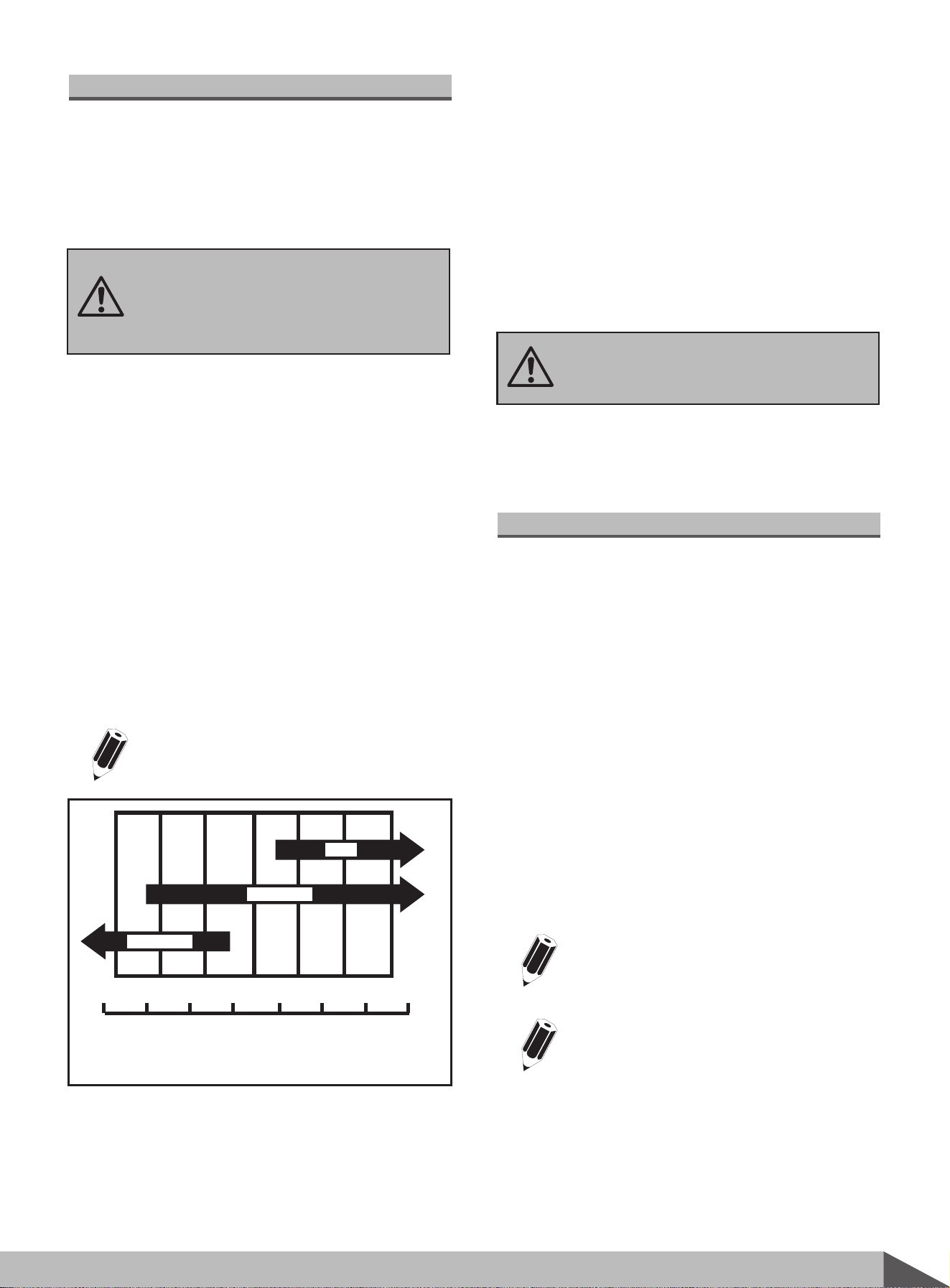
3.1 Run rammer at the full throttle position (a)
for maximum performance.
Guide rammer with its handle. Allow
machine to pull itself forward. Do not try to
over-power the machine.
For best compaction, the shoe must hit the
ground flat (b), not on its toe or heel. This
will save on excessive shoe wear.
When operating the rammer, keep
feet clear from the Bottom plate to
avoid personal injury.
b
3.2
3.3
4.
4.2
4.3
4.4
Put the throttle lever towards to FAST position.
The rammer will commence the pounding action.
Guide the rammer by handrail to move
automatically. The rammer will show the best
effect if keep it in balance. Push the handrail to
make the rammer unstable, which will damage
the eninge.
3.
Stop the engine while leaving the
operating position.
a
MAINTENANCE
Maintaining your upright rammer will insure long
life to the machine and its components.
1.
Turn off engine. Engine must be cool.
2.
Keep the engine’s throttle lever in its SLOW
position, and remove spark plug wire from spark
plug and secure.
3. Inspect the general condition of the upright
rammer. Check for loose screws, misalignment
or binding of moving parts, cracked or broken
parts, and any other condition that may affect
its safe operation.
4.
Remove all debris from the upright rammer with
a soft brush, vacuum, or compressed air. Then
use a premium quality lightweight machine oil
to lubricate all moving parts.
6.
Replace spark plug wire.
Engine maintenance
Refer to the Engine Manual included in your plate
upright rammer for the information on engine
maintenance. Your engine manual provides detailed
information for performing the tasks.
1. Drain the fuel tank completely. Stored fuel
containing ethanol or MTBE can start to go stale
in 30 days. Stale fuel has high gum content and
can clog the carburetor and restrict fuel flow.
2. Start the engine and allow it to run until it stops.
This ensures no fuel is left in the carburetor. Run
the engine until it stops. This helps prevent
deposits from forming inside the carburetor and
possible engine damage.
3. While the engine is still warm, drain the oil from
the engine. Refill with fresh oil of the grade
recommended in the Engine Manual.
4. Allow the engine to cool. Remove the spark plug
and put 60 ml of SAE-30 of high quality motor
oil into the cylinder. Pull the starter rope slowly
to distribute the oil. Replace the spark plug.
STORAGE
If the plate upright rammer will not be used for a
period longer than 30 days, following the steps
below to prepare your unit for storage.
Never use a “pressure washer” to clean
your upright rammer. Water can penetrate
tight areas of the unit and cause damage
to spindles, pulleys, bearings, or the engine.
The use of pressure washers will result in
shortened life and reduce serviceability.
Remove the spark plug and drain all of
the oil from the cylinder before
attempting to start the unit after storage.
11
Upright rammer
Preventive Maintenance
5.
Clean the bottom of the upright rammer base
as soon as it begins to pick up soil being
compacted. The unit can not do a good job if
the bottom surface is not smooth and clean.
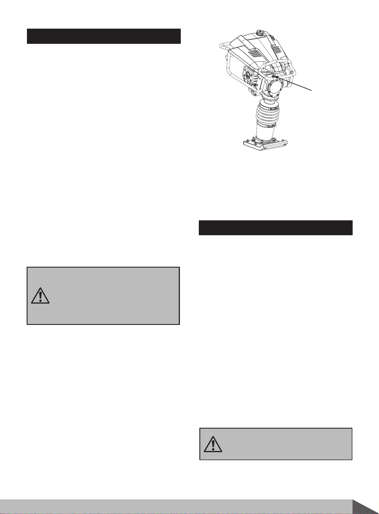
Checking Oil Level of Ramming System
1. Place the rammer on a level surface. Its shoe rest
on the ground.
2. Checking the oil level through the oil window.
Proper ramming system lubrication is indicated
when approximately 1/2-3/4 of the window is full.
3. If the oil is not visible, oil must be added through
the oil filling bolt.
4. Oil recommended: generally SAE 10W30 is
recommended.
5. After adding oil, screw the oil filling bolt tightly.
Oil filling bolt
5. Use clean cloths to clean off the outside of the
upright rammer and to keep the air vents free
of obstructions.
6. Carefully fold the upper handle down. Do not
allow control cables to become pinched or bent.
Do not use strong detergents or
petroleum based cleaners when
cleaning plastic parts. Chemicals can
damage plastics.
12
Upright rammer
7. Store your plate upright rammer in upright
position in a clean, dry building that has good
Do not store upright rammer with fuel
in a non-ventilated area where fuel
fumes may reach flame, sparks, pilot
lights or any ignition sources.
Use only approved fuel containers.
See technical data for the weight of the machine.
To avoid burns or fire hazards, let engine cool
before lifting / transporting machine or storing
indoors.
The unit must be transported in the upright position
to prevent fuel from spilling. Do not lay machine
on its side or top.
Secure or tie down unit using the lifting handle to
prevent machine from sliding or tipping over.
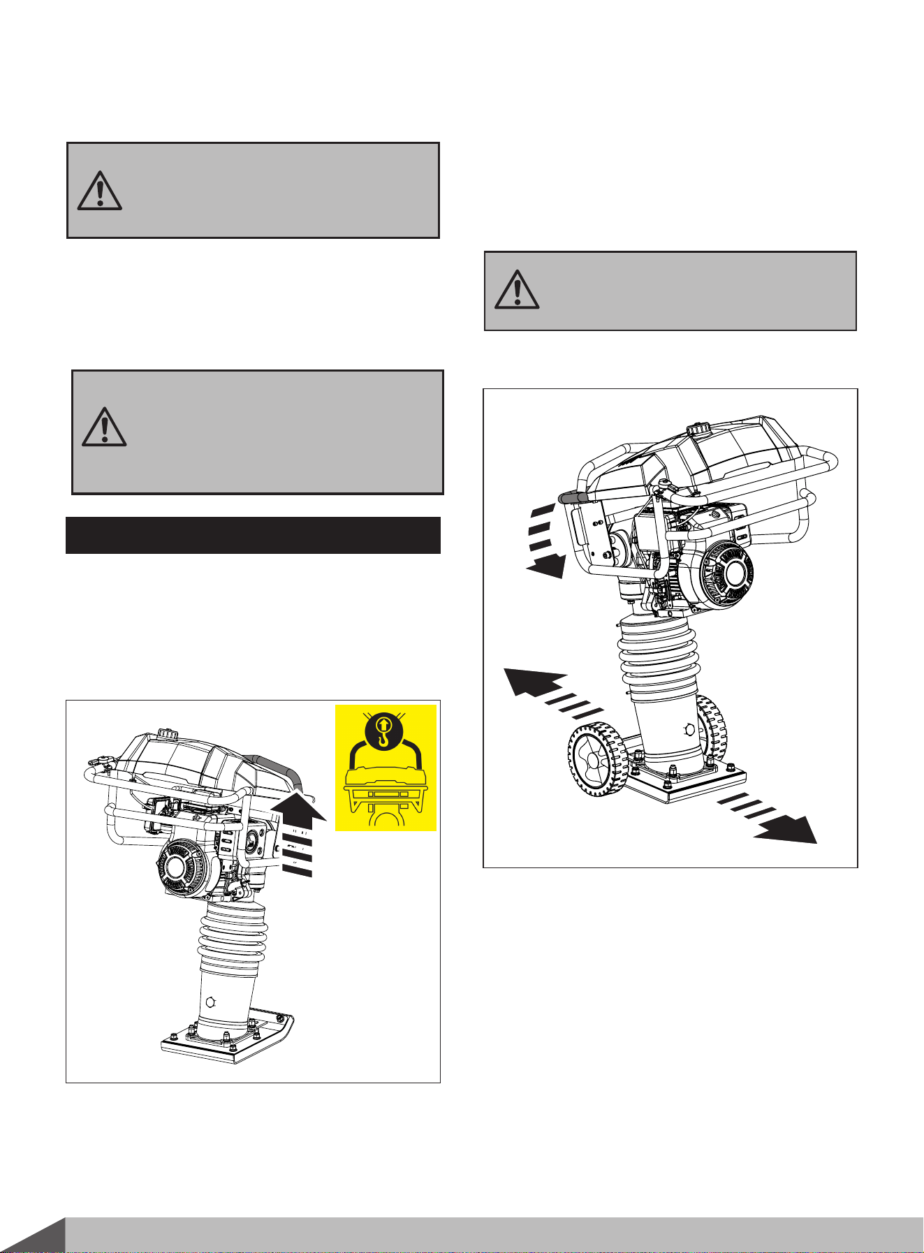
LIFTING / TRANSPORTING
8.
Machine may fall and cause damage or
injury if lifted incorrectly. Lift using
handles at base of plate.
The unit can be lifted by the handles in front and
back of the unit as shown.
Lifting
Transporting
If user buy the optional wheel, follow the instruction
of wheel assembly to assemble wheel first, then
transport via using wheels.
If user haven't bought the optional wheel, move
carefully and securely in an upright position. With
additional assistance, strap the rammer to a dolly
(Dolly and straps not included) capable of
supporting the weight of rammer. Then carefully
move the rammer to the work location.

13
Upright rammer
Problem
Cause Remedy
Engine fails to
start.
1. Spark plug wire disconnected.
2. Out of fuel or stale fuel.
3. Throttle control lever not in correct
starting position.
4. Choke not in ON Position.
5. Blocked fuel line.
6. Fouled spark plug.
7. Engine flooding.
1. Attach spark plug wire securely to
spark plug.
2. Fill with clean, fresh gasoline.
3. Move throttle control lever to start position.
4. Throttle must be positioned at choke
for a cold start.
5. Clean the fuel line.
6. Clean, adjust gap, or replace.
7. Wait a few minutes to restart, but do
not prime.
Engine runs
erratically.
1. Spark plug wire loose.
2. Unit running on CHOKE.
3. Blocked fuel line or stale fuel.
4. Vent plugged.
5. Water or dirt in fuel system.
6. Dirty air cleaner.
1. Connect and tighten spark plug wire.
2. Move choke lever to OFF.
3. Clean fuel line. Fill tank with clean,
fresh gasoline.
4. Clear vent.
5. Drain fuel tank. Refill with fresh fuel.
6. Clean or replace air cleaner.
Engine overheats.
1. Engine oil level low.
2. Dirty air cleaner.
3. Air flow restricted.
1. Fill crankcase with proper oil.
2. Clean air cleaner.
3. Remove blower housing and clean.
Engine will not stop
when throttle control
is positioned at stop,
or engine speed does
not increase properly
when throttle control
is adjusted.
Debris interfering with throttle
linkage.
Clean dirt and debris.
upright rammer is
difficult to control when
pounding (machine
jumps or lurches
Too high engine speed on hard
ground.
Set the throttle lever at lower speed.
TROUBLE SHOOTING
14
Upright rammer
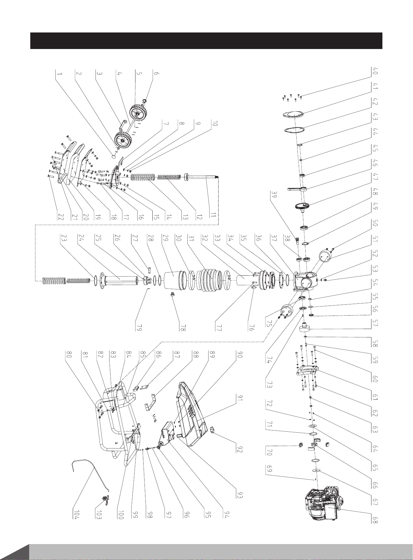
PARTS SCHEDULE

15
Upright rammer
293500000M100
No.
1
2
3
4
5
6
7
8
9
10
11
12
13
14
15
16
17
18
19
20
21
22
23
24
25
26
27
28
29
30
31
32
33
34
35
36
37
38
39
40
41
42
43
44
45
46
47
48
49
50
No.
51
52
53
54
55
56
57
58
59
60
61
62
63
64
65
66
67
68
69
70
71
72
73
74
75
76
77
78
79
80
81
82
83
84
85
86
87
88
89
90
91
92
93
94
95
96
97
98
99
100
101
102
Description
Wheel Cap
Flat Washer 12
Axle Fixing Plate
Axle
Pin 2.5×25
Wheel
Axle Support Plate
Flat Washer 12
Spring Washer 12
Lock Nut
Piston Rod
Big Spring
Small Spring
Base
Spring Washer 10
Screw M10×50
Screw M10×25
Upper Baseplate
Vibration Damper Plate
Lower Baseplate
Bolt M12×80
Bolt M12×60
O-Ring 95×3.55
Cylinder Weldment
Pin 6×50
Piston
Pin Shaft
O-Ring 92.5×3.55
Lower Connecter
Hose Clamp
*
180×20
Rubber Sleeve
Upper Connecter
Bolt M10×45
Flat Washer 10
Upper Connecter Gasket
O-Ring 106×3.55
Gearbox
Deep Groove Ball Bearing6305-2Z
Driving Gear
Bolt M6×20
Gearbox Cover
Gearbox Sealing Gasket
Circlip For Hole 47
Circlip For Shaft A20
Deep Groove Ball Bearing 6204-2Z
Connecting Rod
Gear
Deep Groove Ball Bearing 6207-2Z
Circlip For Hole 62
Screw M10×30
Q’ty
2
4
1
1
6
2
1
13
12
10
1
2
2
1
28
4
4
1
1
1
4
8
1
1
1
1
1
2
1
2
1
1
2
16
1
1
1
1
1
7
1
1
1
1
2
1
1
1
1
4
Description
Damping Block
Flat Washer
Plug M14×1.5
Circlip A25
O-Ring 38.7×1.8
Duct Plug
Clutch Housing
Flat Washer
Bolt M8×25
Bolt M10×45
Coupling Flange between Gear Box and Engine
Screw M10×40
Nut 12×1.25
Bolt
Baffle Plate
Axle Sleeve
Baffle Plate
Engine
Arch Key 4×13.2
Centrifugal Block
Tension Spring
Spring Washer 5
Rubber Oil Seal 40×68×8
Flat Key C5×23
Deep Groove Ball Bearing 6007-2Z
Bolt M12×45
Bolt M10×50
Transparent Window for oil checking
Criclip A16
Screw M10×20
Self-tapping Screw ST8×25
Bolt M6×16
Spring Washer 6
Flat Washer 6
Handle Weldment
Damping Knot
Location Plate
Location Bracing Plate
Flat Washer 8
Nut M8
Dash Board
Oil Tank Cap
Oil Tank filter net
Oil Tank Assy
Oil Tank Switch
Rubber Intake Hose-1
Filter Bowl
Spring Clamp
Rubber Intake Hose-2
Screw M8×25
Throttle Handle
Throttle Control Cable
Q’ty
2
1
1
1
1
1
1
1
1
4
1
4
1
2
1
1
1
1
1
4
2
2
1
2
1
4
4
1
1
4
4
6
6
7
1
1
1
1
4
4
1
1
1
1
1
1
1
4
1
4
1
1