
INSTRUCTION MANUAL
Cordless Compact Router
18~20V
Read before use.
IMPORTANT: Read Before Using
左上角加
logo和
slogan,电
池去掉,底部
加Made in
China。说明
书重新排版
INSTRUCTION MANUAL
Cordless Compact Router
18~20V
Read before use.
IMPORTANT: Read Before Using
左上角加
logo和
slogan,电
池去掉,底部
加Made in
China。说明
书重新排版
INSTRUCTION MANUAL
Cordless Compact Router
18~20V
Read before use.
IMPORTANT: Read Before Using
左上角加
logo和
slogan,电
池去掉,底部
加Made in
China。说明
书重新排版
INSTRUCTION MANUAL
Cordless Compact Router
18~20V
Read before use.
IMPORTANT: Read Before Using
左上角加
logo和
slogan,电
池去掉,底部
加Made in
China。说明
书重新排版
INSTRUCTION MANUAL
Cordless Compact Router
18~20V
Read before use.
IMPORTANT: Read Before Using
左上角加
logo和
slogan,电
池去掉,底部
加Made in
China。说明
书重新排版
INSTRUCTION MANUAL
Cordless Compact Router
18~20V
Read before use.
IMPORTANT: Read Before Using
左上角加
logo和
slogan,电
池去掉,底部
加Made in
China。说明
书重新排版
YOUR ULTIMATE POWER TOOL PARTNER
MADE IN CHINA
INSTRUCTION MANUAL
Cordless Compact Router
18~20V
Read before use.
IMPORTANT: Read Before Using
左上角加
logo和
slogan,电
池去掉,底部
加Made in
China。说明
书重新排版
2
SPECIFICATIONS
Model RTDCB20
Collet Chuck Capacity 1/4"
No-load Speed 10,000 - 28,000/min
Rated Voltage D.C. 18~20 V
Net Weight 1.8 - 2.1 kg
• Due to our continuing program of research and development, the specifications herein are subject to change
without notice.
• Specifications may differ from country to country.
SAFETY WARNINGS
General power tool safety warnings
Save all warnings and instruc-
tions for future reference.
The term "power tool" in the warnings refers to your
mains-operated (corded) power tool or battery-operated
(cordless) power tool.
Work area safety
1. Keep work area clean and well lit. Cluttered or
dark areas invite accidents.
2. Do not operate power tools in explosive atmo-
spheres, such as in the presence of flammable
liquids, gases or dust. Power tools create sparks
which may ignite the dust or fumes.
3. Keep children and bystanders away while
operating a power tool. Distractions can cause
you to lose control.
Electrical Safety
1. Power tool plugs must match the outlet. Never
modify the plug in any way. Do not use any
adapter plugs with earthed (grounded) power
tools. Unmodified plugs and matching outlets will
reduce risk of electric shock.
2. Avoid body contact with earthed or grounded
surfaces, such as pipes, radiators, ranges and
refrigerators. There is an increased risk of elec-
tric shock if your body is earthed or grounded.
3. Do not expose power tools to rain or wet con-
ditions. W ater entering a power tool will increase
the risk of electric shock.
4. Do not abuse the cord. Never use the cord for
carrying, pulling or unplugging the power tool.
Keep cord away from heat, oil, sharp edges
or moving parts. Damaged or entangled cords
increase the risk of electric shock.
5. When operating a power tool outdoors, use an
extension cord suitable for outdoor use. Use of
a cord suitable for outdoor use reduces the risk of
electric shock.
6. If operating a power tool in a damp location is
unavoidable, use a ground fault circuit inter-
rupter (GFCI) protected supply. Use of a GFCI
reduces the risk of electric shock.
7. Power tools can produce electromagnetic
fields (EMF) that are not harmful to the user.
However, users of pacemakers and other similar
medical devices should contact the maker of their
device and/or doctor for advice before operating
this power tool.
Personal Safety
1. Stay alert, watch what you are doing and use
common sense when operating a power tool.
Do not use a power tool while you are tired or
under the influence of drugs, alcohol or med-
ication. A moment of inattention while operating
power tools may result in serious personal injury.
2. Use personal protective equipment. Always
wear eye protection. Protective equipment such
as a dust mask, non-skid safety shoes, hard hat or
hearing protection used for appropriate conditions
will reduce personal injuries.
3. Prevent unintentional starting. Ensure the
switch is in the off-position before connecting
to power source and/or battery pack, picking
up or carrying the tool. Carrying power tools with
your finger on the switch or energising power tools
that have the switch on invites accidents.
4. Remove any adjusting key or wrench before
turning the power tool on. A wrench or a key left
attached to a rotating part of the power tool may
result in personal injury.
WARNING: Read all safety warnings, instruc-
tions, illustrations and specifications provided with this
power tool. Failure to follow all instructions listed below
may result in electric shock, fire and/or serious injury.

2
SPECIFICATIONS
Model
RTDCB20
Collet Chuck Capacity 1/4"
No-load Speed 10,000 - 28,000/min
Rated Voltage
D.C. 18~20 V
Net Weight 1.8 - 2.1 kg
• Due to our continuing program of research and development, the specifications herein are subject to change
without notice.
• Specifications may differ from country to country.
SAFETY WARNINGS
General power tool safety warnings
Save all warnings and instruc-
tions for future reference.
The term "power tool" in the warnings refers to your
mains-operated (corded) power tool or battery-operated
(cordless) power tool.
Work area safety
1. Keep work area clean and well lit. Cluttered or
dark areas invite accidents.
2. Do not operate power tools in explosive atmo-
spheres, such as in the presence of flammable
liquids, gases or dust. Power tools create sparks
which may ignite the dust or fumes.
3. Keep children and bystanders away while
operating a power tool. Distractions can cause
you to lose control.
Electrical Safety
1. Power tool plugs must match the outlet. Never
modify the plug in any way. Do not use any
adapter plugs with earthed (grounded) power
tools. Unmodified plugs and matching outlets will
reduce risk of electric shock.
2. Avoid body contact with earthed or grounded
surfaces, such as pipes, radiators, ranges and
refrigerators. There is an increased risk of elec-
tric shock if your body is earthed or grounded.
3. Do not expose power tools to rain or wet con-
ditions. W ater entering a power tool will increase
the risk of electric shock.
4. Do not abuse the cord. Never use the cord for
carrying, pulling or unplugging the power tool.
Keep cord away from heat, oil, sharp edges
or moving parts. Damaged or entangled cords
increase the risk of electric shock.
5. When operating a power tool outdoors, use an
extension cord suitable for outdoor use. Use of
a cord suitable for outdoor use reduces the risk of
electric shock.
6. If operating a power tool in a damp location is
unavoidable, use a ground fault circuit inter-
rupter (GFCI) protected supply. Use of a GFCI
reduces the risk of electric shock.
7. Power tools can produce electromagnetic
fields (EMF) that are not harmful to the user.
However, users of pacemakers and other similar
medical devices should contact the maker of their
device and/or doctor for advice before operating
this power tool.
Personal Safety
1. Stay alert, watch what you are doing and use
common sense when operating a power tool.
Do not use a power tool while you are tired or
under the influence of drugs, alcohol or med-
ication. A moment of inattention while operating
power tools may result in serious personal injury.
2. Use personal protective equipment. Always
wear eye protection. Protective equipment such
as a dust mask, non-skid safety shoes, hard hat or
hearing protection used for appropriate conditions
will reduce personal injuries.
3. Prevent unintentional starting. Ensure the
switch is in the off-position before connecting
to power source and/or battery pack, picking
up or carrying the tool. Carrying power tools with
your finger on the switch or energising power tools
that have the switch on invites accidents.
4. Remove any adjusting key or wrench before
turning the power tool on. A wrench or a key left
attached to a rotating part of the power tool may
result in personal injury.
WARNING: Read all safety warnings, instruc-
tions, illustrations and specifications provided with this
power tool. Failure to follow all instructions listed below
may result in electric shock, fire and/or serious injury.
INSTRUCTION MANUAL
Cordless Compact Router
18~20V
Read before use.
IMPORTANT: Read Before Using
左上角加
logo和
slogan,电
池去掉,底部
加Made in
China。说明
书重新排版
INSTRUCTION MANUAL
Cordless Compact Router
18~20V
Read before use.
IMPORTANT: Read Before Using
左上角加
logo和
slogan,电
池去掉,底部
加Made in
China。说明
书重新排版
INSTRUCTION MANUAL
Cordless Compact Router
18~20V
Read before use.
IMPORTANT: Read Before Using
左上角加
logo和
slogan,电
池去掉,底部
加Made in
China。说明
书重新排版
INSTRUCTION MANUAL
Cordless Compact Router
18~20V
Read before use.
IMPORTANT: Read Before Using
左上角加
logo和
slogan,电
池去掉,底部
加Made in
China。说明
书重新排版
INSTRUCTION MANUAL
Cordless Compact Router
18~20V
Read before use.
IMPORTANT: Read Before Using
左上角加
logo和
slogan,电
池去掉,底部
加Made in
China。说明
书重新排版
INSTRUCTION MANUAL
Cordless Compact Router
18~20V
Read before use.
IMPORTANT: Read Before Using
左上角加
logo和
slogan,电
池去掉,底部
加Made in
China。说明
书重新排版
2
SPECIFICATIONS
Model
RTDCB20
Collet Chuck Capacity
1/4"
No-load Speed
10,000 - 28,000/min
Rated Voltage
D.C. 18~20 V
Net Weight
1.8 - 2.1 kg
• Due to our continuing program of research and development, the specifications herein are subject to change
without notice.
• Specifications may differ from country to country.
SAFETY WARNINGS
General power tool safety warnings
Save all warnings and instruc-
tions for future reference.
The term "power tool" in the warnings refers to your
mains-operated (corded) power tool or battery-operated
(cordless) power tool.
Work area safety
1. Keep work area clean and well lit. Cluttered or
dark areas invite accidents.
2. Do not operate power tools in explosive atmo-
spheres, such as in the presence of flammable
liquids, gases or dust. Power tools create sparks
which may ignite the dust or fumes.
3. Keep children and bystanders away while
operating a power tool. Distractions can cause
you to lose control.
Electrical Safety
1. Power tool plugs must match the outlet. Never
modify the plug in any way. Do not use any
adapter plugs with earthed (grounded) power
tools. Unmodified plugs and matching outlets will
reduce risk of electric shock.
2. Avoid body contact with earthed or grounded
surfaces, such as pipes, radiators, ranges and
refrigerators. There is an increased risk of elec-
tric shock if your body is earthed or grounded.
3. Do not expose power tools to rain or wet con-
ditions. W ater entering a power tool will increase
the risk of electric shock.
4. Do not abuse the cord. Never use the cord for
carrying, pulling or unplugging the power tool.
Keep cord away from heat, oil, sharp edges
or moving parts. Damaged or entangled cords
increase the risk of electric shock.
5. When operating a power tool outdoors, use an
extension cord suitable for outdoor use. Use of
a cord suitable for outdoor use reduces the risk of
electric shock.
6. If operating a power tool in a damp location is
unavoidable, use a ground fault circuit inter-
rupter (GFCI) protected supply. Use of a GFCI
reduces the risk of electric shock.
7. Power tools can produce electromagnetic
fields (EMF) that are not harmful to the user.
However, users of pacemakers and other similar
medical devices should contact the maker of their
device and/or doctor for advice before operating
this power tool.
Personal Safety
1. Stay alert, watch what you are doing and use
common sense when operating a power tool.
Do not use a power tool while you are tired or
under the influence of drugs, alcohol or med-
ication. A moment of inattention while operating
power tools may result in serious personal injury.
2. Use personal protective equipment. Always
wear eye protection. Protective equipment such
as a dust mask, non-skid safety shoes, hard hat or
hearing protection used for appropriate conditions
will reduce personal injuries.
3. Prevent unintentional starting. Ensure the
switch is in the off-position before connecting
to power source and/or battery pack, picking
up or carrying the tool. Carrying power tools with
your finger on the switch or energising power tools
that have the switch on invites accidents.
4. Remove any adjusting key or wrench before
turning the power tool on. A wrench or a key left
attached to a rotating part of the power tool may
result in personal injury.
WARNING: Read all safety warnings, instruc-
tions, illustrations and specifications provided with this
power tool. Failure to follow all instructions listed below
may result in electric shock, fire and/or serious injury.
3
5. Do not overreach. Keep proper footing and
balance at all times. This enables better control
of the power tool in unexpected situations.
6. Dress properly. Do not wear loose clothing or
jewellery. Keep your hair and clothing away
from moving parts. Loose clothes, jewellery or
long hair can be caught in moving parts.
7. If devices are provided for the connection of
dust extraction and collection facilities, ensure
these are connected and properly used. Use of
dust collection can reduce dust-related hazards.
8. Do not let familiarity gained from frequent use
of tools allow you to become complacent and
ignore tool safety principles. A careless action can
cause severe injury within a fraction of a second.
Power tool use and care
1. Do not force the power tool. Use the correct
power tool for your application. The correct
power tool will do the job better and safer at the
rate for which it was designed.
2. Do not use the power tool if the switch does
not turn it on and off. Any power tool that cannot
be controlled with the switch is dangerous and
must be repaired.
3. Disconnect the plug from the power source
and/or remove the battery pack, if detachable,
from the power tool before making any adjust-
ments, changing accessories, or storing power
tools. Such preventive safety measures reduce
the risk of starting the power tool accidentally.
4. Store idle power tools out of the reach of chil-
dren and do not allow persons unfamiliar with
the power tool or these instructions to operate
the power tool. Power tools are dangerous in the
hands of untrained users.
5. Maintain power tools and accessories. Check
for misalignment or binding of moving parts,
breakage of parts and any other condition that
may affect the power tool’s operation. If dam-
aged, have the power tool repaired before use.
Many accidents are caused by poorly maintained
power tools.
6. Keep cutting tools sharp and clean. Properly
maintained cutting tools with sharp cutting edges
are less likely to bind and are easier to control.
7. Use the power tool, accessories and tool bits
etc. in accordance with these instructions, tak-
ing into account the working conditions and
the work to be performed. Use of the power tool
for operations different from those intended could
result in a hazardous situation.
8. Keep handles and grasping surfaces dry, clean
and free from oil and grease. Slippery handles and
grasping surfaces do not allow for safe handling and
control of the tool in unexpected situations.
9. When using the tool, do not wear cloth work
gloves which may be entangled. The entangle-
ment of cloth work gloves in the moving parts may
result in personal injury.
Service
1. Have your power tool serviced by a qualified
repair person using only identical
replacement parts. This will ensure that the
safety of the power tool is maintained.
2. Never service damaged battery packs. Service
of battery packs should only be performed by the
manufacturer or authorized service providers.
3. Follow instruction for lubricating and chang-
ing accessories.
4. Keep handles dry, clean and free from oil and
grease.
Cordless Router safety warnings
1.
Hold power tool by insulated gripping surfaces,
because the cutter may contact hidden wiring.
Cutting a "live" wire may make exposed metal parts
of the power tool "live" and shock the operator.
2.
Use clamps or another practical way to secure
and support the workpiece to a stable plat-
form. Holding the work by your hand or against
the body leaves it unstable and may lead to loss of
control.
3.
Wear hearing protection during extended
period of operation.
4.
Handle the router bits very carefully.
5.
Check the router bit carefully for cracks or
damage before operation. Replace cracked or
damaged bit immediately.
6.
Avoid cutting nails. Inspect for and remove all
nails from the workpiece before operation.
7.
Hold the tool firmly.
8.
Keep hands away from rotating parts.
9.
Make sure the router bit is not contacting the
workpiece before the switch is turned on.
10.
Before using the tool on an actual workpiece,
let it run for a while. Watch for vibration or
wobbling that could indicate improperly
installed bit.
11.
Be careful of the router bit rotating direction
and the feed direction.
12.
Do not leave the tool running. Operate the tool
only when hand-held.
13.
Always switch off and wait for the router bit to
come to a complete stop before removing the
tool from workpiece.
14.
Do not touch the router bit immediately after
operation; it may be extremely hot and could
burn your skin.
15.
Do not smear the tool base carelessly with
thinner, gasoline, oil or the like. They may
cause cracks in the tool base.
16.
Use router bits of the correct shank diameter
suitable for the speed of the tool.
17.
Some material contains chemicals which may
be toxic. Take caution to prevent dust inhala-
tion and skin contact. Follow material supplier
safety data.
18.
Always use the correct dust mask/respirator
for the material and application you are work-
ing with.
19.
Before using the tool on an actual workpiece,
let it run for a while. Watch for vibration or
wobbling that could indicate improperly
installed bit.
20.
Be careful of the router bit rotating direction
and the feed direction.
1

3
5. Do not overreach. Keep proper footing and
balance at all times. This enables better control
of the power tool in unexpected situations.
6. Dress properly. Do not wear loose clothing or
jewellery. Keep your hair and clothing away
from moving parts. Loose clothes, jewellery or
long hair can be caught in moving parts.
7. If devices are provided for the connection of
dust extraction and collection facilities, ensure
these are connected and properly used. Use of
dust collection can reduce dust-related hazards.
8. Do not let familiarity gained from frequent use
of tools allow you to become complacent and
ignore tool safety principles. A careless action can
cause severe injury within a fraction of a second.
Power tool use and care
1. Do not force the power tool. Use the correct
power tool for your application. The correct
power tool will do the job better and safer at the
rate for which it was designed.
2. Do not use the power tool if the switch does
not turn it on and off. Any power tool that cannot
be controlled with the switch is dangerous and
must be repaired.
3. Disconnect the plug from the power source
and/or remove the battery pack, if detachable,
from the power tool before making any adjust-
ments, changing accessories, or storing power
tools. Such preventive safety measures reduce
the risk of starting the power tool accidentally.
4. Store idle power tools out of the reach of chil-
dren and do not allow persons unfamiliar with
the power tool or these instructions to operate
the power tool. Power tools are dangerous in the
hands of untrained users.
5. Maintain power tools and accessories. Check
for misalignment or binding of moving parts,
breakage of parts and any other condition that
may affect the power tool’s operation. If dam-
aged, have the power tool repaired before use.
Many accidents are caused by poorly maintained
power tools.
6. Keep cutting tools sharp and clean. Properly
maintained cutting tools with sharp cutting edges
are less likely to bind and are easier to control.
7. Use the power tool, accessories and tool bits
etc. in accordance with these instructions, tak-
ing into account the working conditions and
the work to be performed. Use of the power tool
for operations different from those intended could
result in a hazardous situation.
8. Keep handles and grasping surfaces dry, clean
and free from oil and grease. Slippery handles and
grasping surfaces do not allow for safe handling and
control of the tool in unexpected situations.
9. When using the tool, do not wear cloth work
gloves which may be entangled. The entangle-
ment of cloth work gloves in the moving parts may
result in personal injury.
Service
1. Have your power tool serviced by a qualified
repair person using only identical
replacement parts. This will ensure that the
safety of the power tool is maintained.
2. Never service damaged battery packs. Service
of battery packs should only be performed by the
manufacturer or authorized service providers.
3. Follow instruction for lubricating and chang-
ing accessories.
4. Keep handles dry, clean and free from oil and
grease.
Cordless Router safety warnings
1.
Hold power tool by insulated gripping surfaces,
because the cutter may contact hidden wiring.
Cutting a "live" wire may make exposed metal parts
of the power tool "live" and shock the operator.
2.
Use clamps or another practical way to secure
and support the workpiece to a stable plat-
form. Holding the work by your hand or against
the body leaves it unstable and may lead to loss of
control.
3.
Wear hearing protection during extended
period of operation.
4.
Handle the router bits very carefully.
5.
Check the router bit carefully for cracks or
damage before operation. Replace cracked or
damaged bit immediately.
6.
Avoid cutting nails. Inspect for and remove all
nails from the workpiece before operation.
7.
Hold the tool firmly.
8.
Keep hands away from rotating parts.
9.
Make sure the router bit is not contacting the
workpiece before the switch is turned on.
10.
Before using the tool on an actual workpiece,
let it run for a while. Watch for vibration or
wobbling that could indicate improperly
installed bit.
11.
Be careful of the router bit rotating direction
and the feed direction.
12.
Do not leave the tool running. Operate the tool
only when hand-held.
13.
Always switch off and wait for the router bit to
come to a complete stop before removing the
tool from workpiece.
14.
Do not touch the router bit immediately after
operation; it may be extremely hot and could
burn your skin.
15.
Do not smear the tool base carelessly with
thinner, gasoline, oil or the like. They may
cause cracks in the tool base.
16.
Use router bits of the correct shank diameter
suitable for the speed of the tool.
17.
Some material contains chemicals which may
be toxic. Take caution to prevent dust inhala-
tion and skin contact. Follow material supplier
safety data.
18.
Always use the correct dust mask/respirator
for the material and application you are work-
ing with.
19.
Before using the tool on an actual workpiece,
let it run for a while. Watch for vibration or
wobbling that could indicate improperly
installed bit.
20.
Be careful of the router bit rotating direction
and the feed direction.
Router
3
5. Do not overreach. Keep proper footing and
balance at all times. This enables better control
of the power tool in unexpected situations.
6. Dress properly. Do not wear loose clothing or
jewellery. Keep your hair and clothing away
from moving parts. Loose clothes, jewellery or
long hair can be caught in moving parts.
7. If devices are provided for the connection of
dust extraction and collection facilities, ensure
these are connected and properly used. Use of
dust collection can reduce dust-related hazards.
8. Do not let familiarity gained from frequent use
of tools allow you to become complacent and
ignore tool safety principles. A careless action can
cause severe injury within a fraction of a second.
Power tool use and care
1. Do not force the power tool. Use the correct
power tool for your application. The correct
power tool will do the job better and safer at the
rate for which it was designed.
2. Do not use the power tool if the switch does
not turn it on and off. Any power tool that cannot
be controlled with the switch is dangerous and
must be repaired.
3. Disconnect the plug from the power source
and/or remove the battery pack, if detachable,
from the power tool before making any adjust-
ments, changing accessories, or storing power
tools. Such preventive safety measures reduce
the risk of starting the power tool accidentally.
4. Store idle power tools out of the reach of chil-
dren and do not allow persons unfamiliar with
the power tool or these instructions to operate
the power tool. Power tools are dangerous in the
hands of untrained users.
5. Maintain power tools and accessories. Check
for misalignment or binding of moving parts,
breakage of parts and any other condition that
may affect the power tool’s operation. If dam-
aged, have the power tool repaired before use.
Many accidents are caused by poorly maintained
power tools.
6. Keep cutting tools sharp and clean. Properly
maintained cutting tools with sharp cutting edges
are less likely to bind and are easier to control.
7. Use the power tool, accessories and tool bits
etc. in accordance with these instructions, tak-
ing into account the working conditions and
the work to be performed. Use of the power tool
for operations different from those intended could
result in a hazardous situation.
8. Keep handles and grasping surfaces dry, clean
and free from oil and grease. Slippery handles and
grasping surfaces do not allow for safe handling and
control of the tool in unexpected situations.
9. When using the tool, do not wear cloth work
gloves which may be entangled. The entangle-
ment of cloth work gloves in the moving parts may
result in personal injury.
Service
1. Have your power tool serviced by a qualified
repair person using only identical
replacement parts. This will ensure that the
safety of the power tool is maintained.
2. Never service damaged battery packs. Service
of battery packs should only be performed by the
manufacturer or authorized service providers.
3. Follow instruction for lubricating and chang-
ing accessories.
4. Keep handles dry, clean and free from oil and
grease.
Cordless Router safety warnings
1.
Hold power tool by insulated gripping surfaces,
because the cutter may contact hidden wiring.
Cutting a "live" wire may make exposed metal parts
of the power tool "live" and shock the operator.
2.
Use clamps or another practical way to secure
and support the workpiece to a stable plat-
form. Holding the work by your hand or against
the body leaves it unstable and may lead to loss of
control.
3.
Wear hearing protection during extended
period of operation.
4.
Handle the router bits very carefully.
5.
Check the router bit carefully for cracks or
damage before operation. Replace cracked or
damaged bit immediately.
6.
Avoid cutting nails. Inspect for and remove all
nails from the workpiece before operation.
7.
Hold the tool firmly.
8.
Keep hands away from rotating parts.
9.
Make sure the router bit is not contacting the
workpiece before the switch is turned on.
10.
Before using the tool on an actual workpiece,
let it run for a while. Watch for vibration or
wobbling that could indicate improperly
installed bit.
11.
Be careful of the router bit rotating direction
and the feed direction.
12.
Do not leave the tool running. Operate the tool
only when hand-held.
13.
Always switch off and wait for the router bit to
come to a complete stop before removing the
tool from workpiece.
14.
Do not touch the router bit immediately after
operation; it may be extremely hot and could
burn your skin.
15.
Do not smear the tool base carelessly with
thinner, gasoline, oil or the like. They may
cause cracks in the tool base.
16.
Use router bits of the correct shank diameter
suitable for the speed of the tool.
17.
Some material contains chemicals which may
be toxic. Take caution to prevent dust inhala-
tion and skin contact. Follow material supplier
safety data.
18.
Always use the correct dust mask/respirator
for the material and application you are work-
ing with.
19.
Before using the tool on an actual workpiece,
let it run for a while. Watch for vibration or
wobbling that could indicate improperly
installed bit.
20.
Be careful of the router bit rotating direction
and the feed direction.
4
21.
Before using the tool on an actual workpiece,
let it run for a while. Watch for vibration or
wobbling that could indicate improperly
installed bit.
22.
Be careful of the router bit rotating direction
and the feed direction.
23.
Do not leave the tool running. Operate the tool
only when hand-held.
24.
Always switch off and wait for the router bit
to come to a complete stop before removing
the tool from workpiece.
25.
Do not touch the router bit immediately after
operation; it may be extremely hot and could
burn your skin.
26.
Do not smear the tool base carelessly with
thinner, gasoline, oil or the like. They may
cause cracks in the tool base.
27.
Use router bits of the correct shank diameter
suitable for the speed of the tool.
28.
Some material contains chemicals which may
be toxic. Take caution to prevent dust inhala-
tion and skin contact. Follow material supplier
safety data.
29.
Always use the correct dust mask/respirator
for the material and application you are work-
ing with.
SAVE THESE INSTRUCTIONS.
Symbols
The followings show the symbols used for tool.
volts
4.
direct current
no load speed
revolutions or reciprocation per minute
Battery life
Tool / battery protection system
The tool is equipped with a tool/battery protection sys-
tem. This system automatically cuts off power to the
motor to extend tool and battery life. The tool will auto-
matically stop during operation if the tool or battery is
placed under one of the following conditions:
Overload protection
When the battery is operated in a manner that causes
it to draw an abnormally high current, the tool automat-
ically stops without any indication. In this situation, turn
WARNING: DO NOT let comfort or familiarity
with product (gained from repeated use) replace
strict adherence to safety rules for the subject
product. MISUSE or failure to follow the safety
rules stated in this instruction manual may cause
serious personal injury.
CAUTION: Always be sure that the tool is
switched off and the battery cartridge is removed
before adjusting or checking function on the tool.
FUNCTIONAL
DESCRIPTION
5
the tool off and stop the application that caused the tool
to become overloaded. Then turn the tool on to restart.
2
4
21.
Before using the tool on an actual workpiece,
let it run for a while. Watch for vibration or
wobbling that could indicate improperly
installed bit.
22.
Be careful of the router bit rotating direction
and the feed direction.
23.
Do not leave the tool running. Operate the tool
only when hand-held.
24.
Always switch off and wait for the router bit
to come to a complete stop before removing
the tool from workpiece.
25.
Do not touch the router bit immediately after
operation; it may be extremely hot and could
burn your skin.
26.
Do not smear the tool base carelessly with
thinner, gasoline, oil or the like. They may
cause cracks in the tool base.
27.
Use router bits of the correct shank diameter
suitable for the speed of the tool.
28.
Some material contains chemicals which may
be toxic. Take caution to prevent dust inhala-
tion and skin contact. Follow material supplier
safety data.
29.
Always use the correct dust mask/respirator
for the material and application you are work-
ing with.
SAVE THESE INSTRUCTIONS.
Symbols
The followings show the symbols used for tool.
volts
4.
direct current
no load speed
revolutions or reciprocation per minute
Battery life
Tool / battery protection system
The tool is equipped with a tool/battery protection sys-
tem. This system automatically cuts off power to the
motor to extend tool and battery life. The tool will auto-
matically stop during operation if the tool or battery is
placed under one of the following conditions:
Overload protection
When the battery is operated in a manner that causes
it to draw an abnormally high current, the tool automat-
ically stops without any indication. In this situation, turn
WARNING: DO NOT let comfort or familiarity
with product (gained from repeated use) replace
strict adherence to safety rules for the subject
product. MISUSE or failure to follow the safety
rules stated in this instruction manual may cause
serious personal injury.
CAUTION: Always be sure that the tool is
switched off and the battery cartridge is removed
before adjusting or checking function on the tool.
FUNCTIONAL
DESCRIPTION
5
the tool off and stop the application that caused the tool
to become overloaded. Then turn the tool on to restart.
6
Overheat protection
When the tool or battery is overheated, the tool stops
automatically and the lamp blinks. In this case, let the
tool and battery cool before turning the tool on again.
Overdischarge protection
When the battery capacity is not enough, the tool stops
automatically. In this case, remove the battery from the
tool and charge the battery.
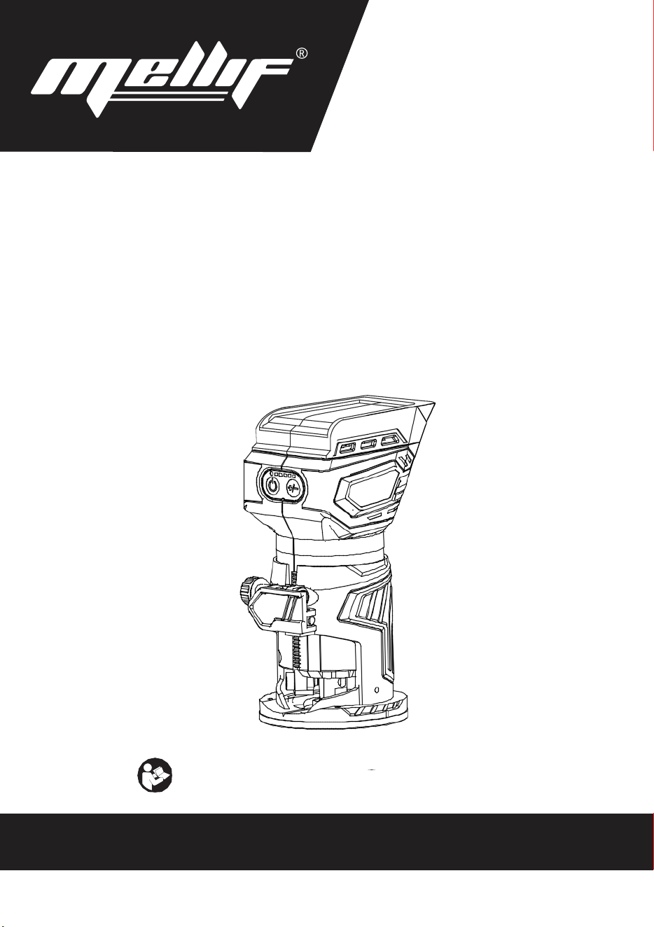
Switch action
To turn on the tool, press the lock/unlock button. The
tool turns into the standby mode. To start the tool, press
the start/stop button in the standby mode. To stop the
tool, press the start/stop button again. The tool turns
into the standby mode. To turn off the tool, press the
lock/unlock button in the standby mode.
► 1. Lock/unlock button 2. Start/stop button
Lighting up the front lamp
To turn on the lamp, press the lock/unlock button. To
turn off the lamp, press the lock/unlock button again.
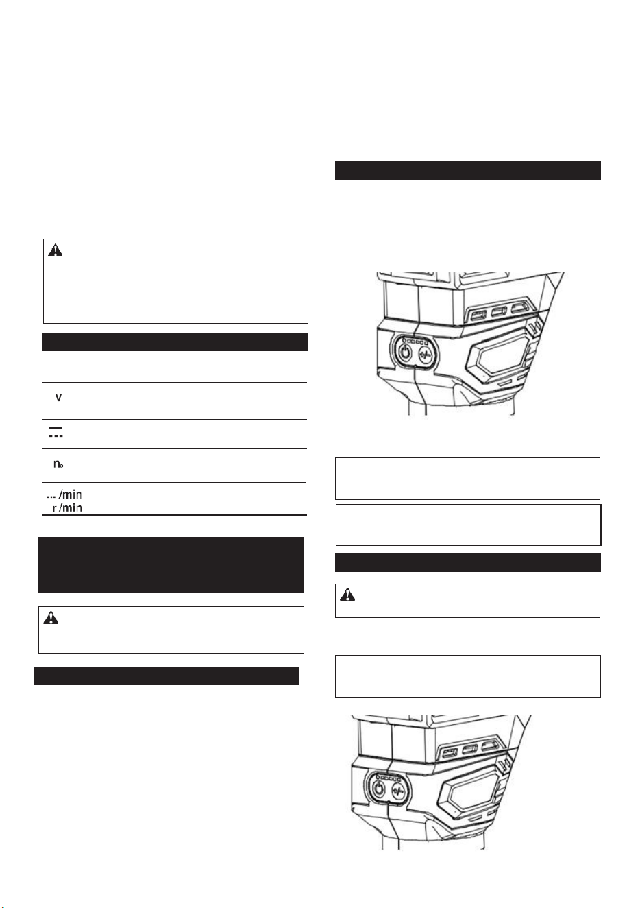
► 1. Speed adjusting dial
Number
Speed
1
12,000/min
2
16,000/min
3
20,000/min
4
24,000/min
5
28,000/min
Electronic function
The tool is equipped with the electronic functions for
easy operation.
• Constant speed control
The speed control function provides the constant
rotation speed regardless of load conditions.
• Soft start
The soft-start function minimizes start-up shock,
and makes the tool start smoothly.
Adjusting cutting depth
To adjust the cutting depth, open the lock lever, then
move the tool base up or down by turning the adjusting
screw. After the adjustment, close the lock lever firmly.
NOTE: You can also stop and turn off the tool by
pressing the lock/unlock button while the tool is
operating.
NOTICE: If the tool is operated continuously at
low speed for a long time, the motor will get over-
loaded, resulting in tool malfunction.
NOTICE: When changing the speed dial from "5"
to "1", turn the dial counterclockwise. Do not turn
the dial clockwise forcibly.
NOTICE: When the tool is overheated, the lamp
flickers. Cool down the tool fully before operating
the tool again.
NOTE: If the tool is left for 10 seconds without any
operation in the standby mode, the tool automatically
turns off and the lamp goes off.
CAUTION: Do not look in the light or see the
source of light directly.
6
Overheat protection
When the tool or battery is overheated, the tool stops
automatically and the lamp blinks. In this case, let the
tool and battery cool before turning the tool on again.
Overdischarge protection
When the battery capacity is not enough, the tool stops
automatically. In this case, remove the battery from the
tool and charge the battery.
Switch action
To turn on the tool, press the lock/unlock button. The
tool turns into the standby mode. To start the tool, press
the start/stop button in the standby mode. To stop the
tool, press the start/stop button again. The tool turns
into the standby mode. To turn off the tool, press the
lock/unlock button in the standby mode.
► 1. Lock/unlock button 2. Start/stop button
Lighting up the front lamp
To turn on the lamp, press the lock/unlock button. To
turn off the lamp, press the lock/unlock button again.
► 1. Speed adjusting dial
Number
Speed
1
12,000/min
2
16,000/min
3
20,000/min
4
24,000/min
5
28,000/min
Electronic function
The tool is equipped with the electronic functions for
easy operation.
• Constant speed control
The speed control function provides the constant
rotation speed regardless of load conditions.
• Soft start
The soft-start function minimizes start-up shock,
and makes the tool start smoothly.
Adjusting cutting depth
To adjust the cutting depth, open the lock lever, then
move the tool base up or down by turning the adjusting
screw. After the adjustment, close the lock lever firmly.
NOTE: You can also stop and turn off the tool by
pressing the lock/unlock button while the tool is
operating.
NOTICE: If the tool is operated continuously at
low speed for a long time, the motor will get over-
loaded, resulting in tool malfunction.
NOTICE: When changing the speed dial from "5"
to "1", turn the dial counterclockwise. Do not turn
the dial clockwise forcibly.
NOTICE: When the tool is overheated, the lamp
flickers. Cool down the tool fully before operating
the tool again.
NOTE: If the tool is left for 10 seconds without any
operation in the standby mode, the tool automatically
turns off and the lamp goes off.
CAUTION: Do not look in the light or see the
source of light directly.
7
Speed adjusting dial
The rotation speed of the tool can be changed by turn-
ing the speed adjusting dial. The table below shows
the number on the dial and the corresponding rotation
speed.
► 1. Lock lever 2. Adjusting screw
NOTE: Use a dry cloth to wipe the dirt off the lens of
the lamp. Be careful not to scratch the lens of lamp, or
it may lower the illumination.
1
2
3
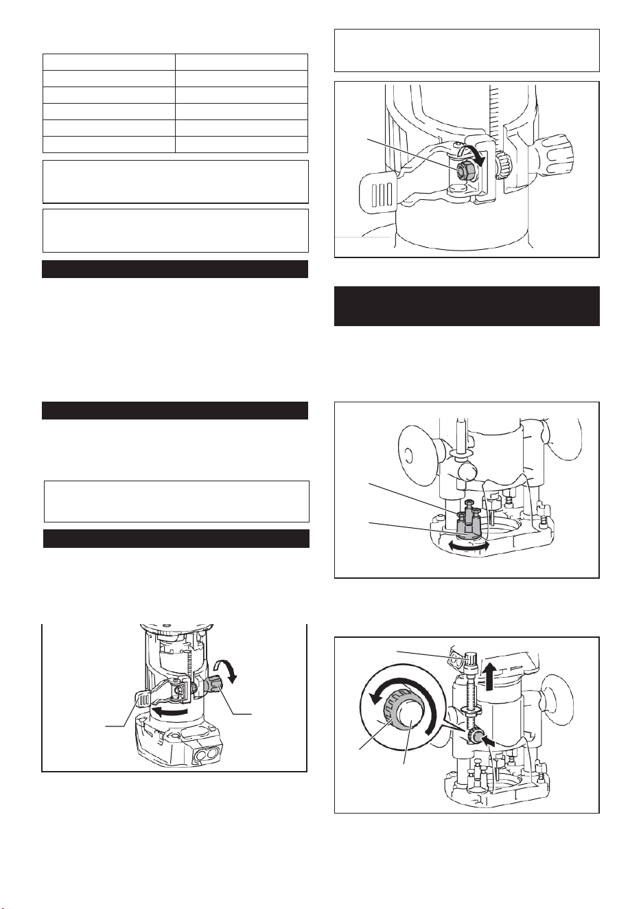
6
Overheat protection
When the tool or battery is overheated, the tool stops
automatically and the lamp blinks. In this case, let the
tool and battery cool before turning the tool on again.
Overdischarge protection
When the battery capacity is not enough, the tool stops
automatically. In this case, remove the battery from the
tool and charge the battery.
Switch action
To turn on the tool, press the lock/unlock button. The
tool turns into the standby mode. To start the tool, press
the start/stop button in the standby mode. To stop the
tool, press the start/stop button again. The tool turns
into the standby mode. To turn off the tool, press the
lock/unlock button in the standby mode.
► 1. Lock/unlock button 2. Start/stop button
Lighting up the front lamp
To turn on the lamp, press the lock/unlock button. To
turn off the lamp, press the lock/unlock button again.
► 1. Speed adjusting dial
Number
Speed
1
12,000/min
2
16,000/min
3
20,000/min
4
24,000/min
5
28,000/min
Electronic function
The tool is equipped with the electronic functions for
easy operation.
• Constant speed control
The speed control function provides the constant
rotation speed regardless of load conditions.
• Soft start
The soft-start function minimizes start-up shock,
and makes the tool start smoothly.
Adjusting cutting depth
To adjust the cutting depth, open the lock lever, then
move the tool base up or down by turning the adjusting
screw. After the adjustment, close the lock lever firmly.
NOTE: You can also stop and turn off the tool by
pressing the lock/unlock button while the tool is
operating.
NOTICE: If the tool is operated continuously at
low speed for a long time, the motor will get over-
loaded, resulting in tool malfunction.
NOTICE: When changing the speed dial from "5"
to "1", turn the dial counterclockwise. Do not turn
the dial clockwise forcibly.
NOTICE: When the tool is overheated, the lamp
flickers. Cool down the tool fully before operating
the tool again.
NOTE: If the tool is left for 10 seconds without any
operation in the standby mode, the tool automatically
turns off and the lamp goes off.
CAUTION: Do not look in the light or see the
source of light directly.
6
Overheat protection
When the tool or battery is overheated, the tool stops
automatically and the lamp blinks. In this case, let the
tool and battery cool before turning the tool on again.
Overdischarge protection
When the battery capacity is not enough, the tool stops
automatically. In this case, remove the battery from the
tool and charge the battery.
Switch action
To turn on the tool, press the lock/unlock button. The
tool turns into the standby mode. To start the tool, press
the start/stop button in the standby mode. To stop the
tool, press the start/stop button again. The tool turns
into the standby mode. To turn off the tool, press the
lock/unlock button in the standby mode.
► 1. Lock/unlock button 2. Start/stop button
Lighting up the front lamp
To turn on the lamp, press the lock/unlock button. To
turn off the lamp, press the lock/unlock button again.
► 1. Speed adjusting dial
Number Speed
1 12,000/min
2 16,000/min
3
20,000/min
4
24,000/min
5 28,000/min
Electronic function
The tool is equipped with the electronic functions for
easy operation.
• Constant speed control
The speed control function provides the constant
rotation speed regardless of load conditions.
• Soft start
The soft-start function minimizes start-up shock,
and makes the tool start smoothly.
Adjusting cutting depth
To adjust the cutting depth, open the lock lever, then
move the tool base up or down by turning the adjusting
screw. After the adjustment, close the lock lever firmly.
NOTE: You can also stop and turn off the tool by
pressing the lock/unlock button while the tool is
operating.
NOTICE: If the tool is operated continuously at
low speed for a long time, the motor will get over-
loaded, resulting in tool malfunction.
NOTICE: When changing the speed dial from "5"
to "1", turn the dial counterclockwise. Do not turn
the dial clockwise forcibly.
NOTICE: When the tool is overheated, the lamp
flickers. Cool down the tool fully before operating
the tool again.
NOTE: If the tool is left for 10 seconds without any
operation in the standby mode, the tool automatically
turns off and the lamp goes off.
CAUTION: Do not look in the light or see the
source of light directly.
7
Speed adjusting dial
The rotation speed of the tool can be changed by turn-
ing the speed adjusting dial. The table below shows
the number on the dial and the corresponding rotation
speed.
► 1. Lock lever 2. Adjusting screw
NOTE: Use a dry cloth to wipe the dirt off the lens of
the lamp. Be careful not to scratch the lens of lamp, or
it may lower the illumination.
1
2
8
4. Push down the tool until the tip of the router bit
touches the flat surface, and then turn the fixing lever to
secure the tool.
► 1. Hex nut
► 1. Fixing lever 2. router bit
5. Press down the stopper pole while pressing the
feed button until it contacts the stopper screw.
Optional accessory
1. Place the tool on the flat surface.
2. Select the stopper screw by rotating the stopper
base.
► 1. Stopper pole 2. Stopper screw 3. Feed button
6. Slide the depth pointer so that the pointer indi-
cates "0" on the scale.
► 1. Stopper screw 2. Stopper base
3. Loosen the stopper pole fixing nut, then pull up the
stopper pole while pressing the feed button.
► 1. Depth pointer
7. Adjust the cutting depth by pulling up the stopper
pole while pressing the feed button.
► 1. Stopper pole 2. Fixing nut 3. Feed button
1
2
1
1
2
1
2
3
1
2
3
1
NOTICE:
If the tool is not secured after closing
the lock lever, tighten the hex nut, and then close
the lock lever.
Adjusting cutting depth with the
plunge base
8
4. Push down the tool until the tip of the router bit
touches the flat surface, and then turn the fixing lever to
secure the tool.
► 1. Hex nut
► 1. Fixing lever 2. router bit
5. Press down the stopper pole while pressing the
feed button until it contacts the stopper screw.
Optional accessory
1. Place the tool on the flat surface.
2. Select the stopper screw by rotating the stopper
base.
► 1. Stopper pole 2. Stopper screw 3. Feed button
6. Slide the depth pointer so that the pointer indi-
cates "0" on the scale.
► 1. Stopper screw 2. Stopper base
3. Loosen the stopper pole fixing nut, then pull up the
stopper pole while pressing the feed button.
► 1. Depth pointer
7. Adjust the cutting depth by pulling up the stopper
pole while pressing the feed button.
► 1. Stopper pole 2. Fixing nut 3. Feed button
1
2
1
1
2
1
2
3
1
2
3
1
NOTICE: If the tool is not secured after closing
the lock lever, tighten the hex nut, and then close
the lock lever.
Adjusting cutting depth with the
plunge base
4
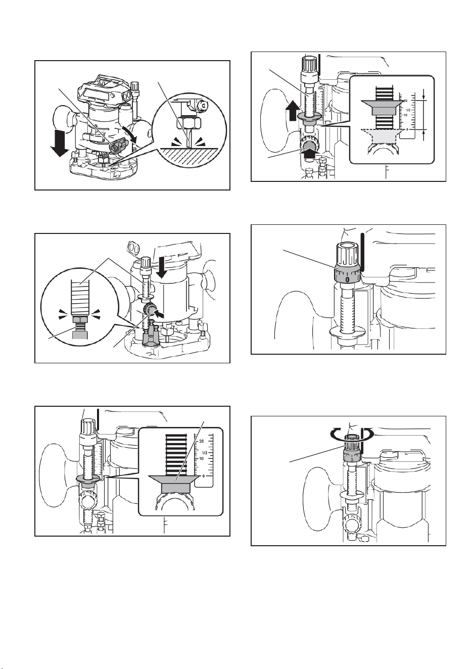
8
4. Push down the tool until the tip of the router bit
touches the flat surface, and then turn the fixing lever to
secure the tool.
► 1. Hex nut
► 1. Fixing lever 2. router bit
5. Press down the stopper pole while pressing the
feed button until it contacts the stopper screw.
Optional accessory
1. Place the tool on the flat surface.
2. Select the stopper screw by rotating the stopper
base.
► 1. Stopper pole 2. Stopper screw 3. Feed button
6. Slide the depth pointer so that the pointer indi-
cates "0" on the scale.
► 1. Stopper screw 2. Stopper base
3. Loosen the stopper pole fixing nut, then pull up the
stopper pole while pressing the feed button.
► 1. Depth pointer
7. Adjust the cutting depth by pulling up the stopper
pole while pressing the feed button.
► 1. Stopper pole 2. Fixing nut 3. Feed button
1
2
1
1
2
1
2
3
1
2
3
1
NOTICE: If the tool is not secured after closing
the lock lever, tighten the hex nut, and then close
the lock lever.
Adjusting cutting depth with the
plunge base
9
► 1. Stopper pole 2. Feed button
8. To perform fine adjustment of the cutting depth,
turn the dial on the stopper pole so that it indicates "0".
► 1. Fixing nut
11. Release the fixing lever.
► 1. Dial
9. Turn the head of the stopper pole to obtain the
desired depth. To increase the depth, turn the head
counterclockwise. To decrease the depth, turn the head
clockwise.
► 1. Fixing lever
ASSEMBLY
Installing or removing router bit
► 1. Head of the stopper pole
10. Tighten the stopper pole fixing nut.
Insert the router bit all the way into the collet cone.
Press the shaft lock and tighten the collet nut with the
wrench or tighten the collet nut securely with the two
wrenches. To remove the bit, follow the installation
procedure in reverse.
1
2
1
NOTICE: Do not tighten the collet nut without
inserting the bit. The collet cone may break.
1
1
1
CAUTION: Always be sure that the tool is
switched off and the battery cartridge is removed
before carrying out any work on the tool.
5
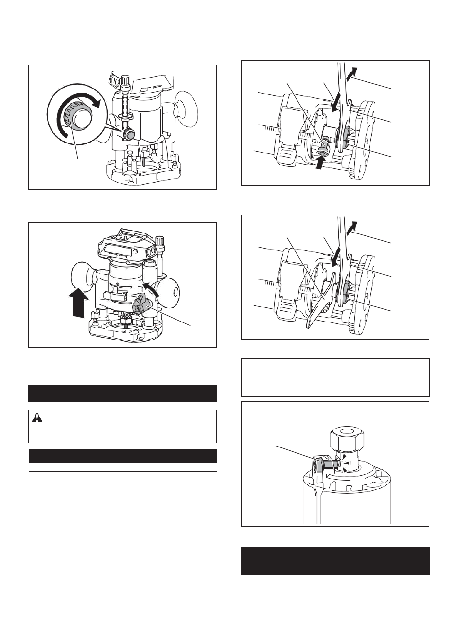
9
► 1. Stopper pole 2. Feed button
8. To perform fine adjustment of the cutting depth,
turn the dial on the stopper pole so that it indicates "0".
► 1. Fixing nut
11. Release the fixing lever.
► 1. Dial
9. Turn the head of the stopper pole to obtain the
desired depth. To increase the depth, turn the head
counterclockwise. To decrease the depth, turn the head
clockwise.
► 1. Fixing lever
ASSEMBLY
Installing or removing router bit
► 1. Head of the stopper pole
10. Tighten the stopper pole fixing nut.
Insert the router bit all the way into the collet cone.
Press the shaft lock and tighten the collet nut with the
wrench or tighten the collet nut securely with the two
wrenches. To remove the bit, follow the installation
procedure in reverse.
1
2
1
NOTICE: Do not tighten the collet nut without
inserting the bit. The collet cone may break.
1
1
1
CAUTION: Always be sure that the tool is
switched off and the battery cartridge is removed
before carrying out any work on the tool.
9
► 1. Stopper pole 2. Feed button
8. To perform fine adjustment of the cutting depth,
turn the dial on the stopper pole so that it indicates "0".
► 1. Fixing nut
11. Release the fixing lever.
► 1. Dial
9. Turn the head of the stopper pole to obtain the
desired depth. To increase the depth, turn the head
counterclockwise. To decrease the depth, turn the head
clockwise.
► 1. Fixing lever
ASSEMBLY
Installing or removing router bit
► 1. Head of the stopper pole
10. Tighten the stopper pole fixing nut.
Insert the router bit all the way into the collet cone.
Press the shaft lock and tighten the collet nut with the
wrench or tighten the collet nut securely with the two
wrenches. To remove the bit, follow the installation
procedure in reverse.
1
2
1
NOTICE: Do not tighten the collet nut without
inserting the bit.
The collet cone may break.
1
1
1
CAUTION: Always be sure that the tool is
switched off and the battery cartridge is removed
before carrying out any work on the tool.
10
► 1. Shaft lock 2. Loosen 3. Tighten 4. Wrench
5. Collet nut
► 1. Lock lever
2. Close the lock lever.
3. Attach the dust nozzle to the router base, and
then tighten the thumb screw.
► 1. Wrench 2. Loosen 3. Tighten 4. Collet nut
► 1. Dust nozzle 2. Thumb screw
► 1. Shaft lock
1. Open the lock lever of the router base, then insert
the tool into the router base aligning the groove on the
tool with the protrusion on the router base.
To remove the base, follow the installation procedure
in reverse.
1
2
3
4
5
1
2
3
1
4
1
1
1 2
Installing or removing the router
base
NOTE: The shaft lock may not return to the original
position when you tighten the collet nut at the instal-
lation of the router bit. The shaft lock returns to the
original position when you start the tool.
6
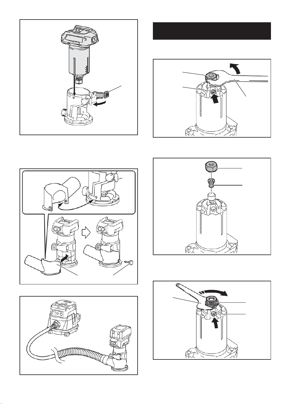
10
► 1. Shaft lock 2. Loosen 3. Tighten 4. Wrench
5. Collet nut
► 1. Lock lever
2. Close the lock lever.
3. Attach the dust nozzle to the router base, and
then tighten the thumb screw.
► 1. Wrench 2. Loosen 3. Tighten 4. Collet nut
► 1. Dust nozzle 2. Thumb screw
► 1. Shaft lock
1. Open the lock lever of the router base, then insert
the tool into the router base aligning the groove on the
tool with the protrusion on the router base.
To remove the base, follow the installation procedure
in reverse.
1
2
3
4
5
1
2
3
1
4
1
1
1 2
Installing or removing the router
base
NOTE: The shaft lock may not return to the original
position when you tighten the collet nut at the instal-
lation of the router bit. The shaft lock returns to the
original position when you start the tool.
11
Optional accessory
1. Press the shaft lock, then loosen the collet nut.
► 1. Base plate
5. Open the lock lever of the offset base, then insert
the tool into the offset base.
► 1. Collet nut 2. Shaft lock 3. Wrench
2. Remove the collet nut and the collet cone.
► 1. Lock lever
6. Mount the belt to the pulley by rotating the belt
manually.
► 1. Collet nut 2. Collet cone
3. Install the pulley on the tool by pressing the shaft
lock and tightening the pulley with the wrench.
► 1. Pulley 2. Belt
7. Close the lock lever.
► 1. Wrench 2. Pulley 3. Shaft lock
4. Loosen the screws on the base plate, and then
remove the base plate.
Installing or removing the offset
base
1
2
3
1
2
1
2
3
1
1
1
2
7
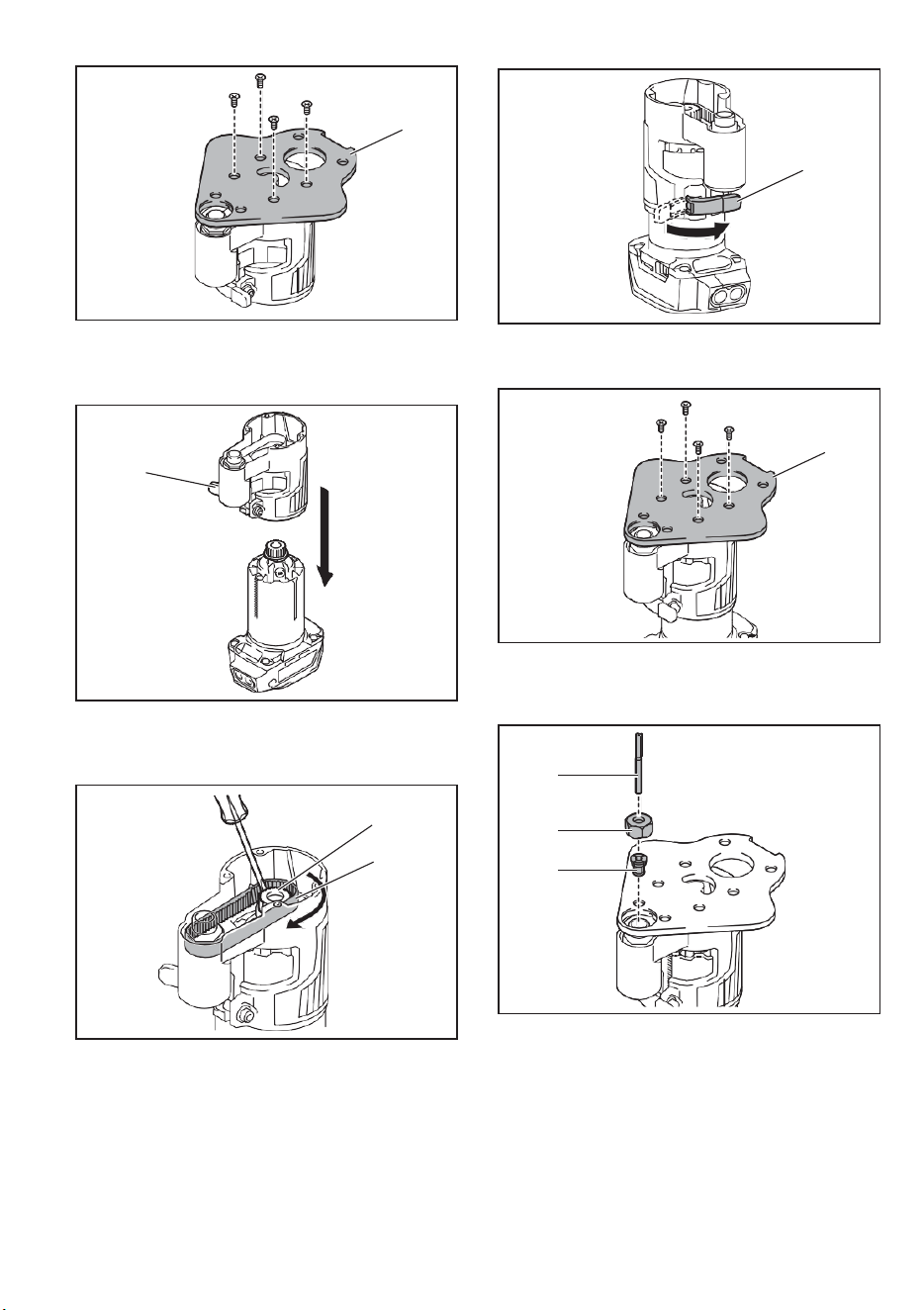
11
Optional accessory
1. Press the shaft lock, then loosen the collet nut.
► 1. Base plate
5. Open the lock lever of the offset base, then insert
the tool into the offset base.
► 1. Collet nut 2. Shaft lock 3. Wrench
2. Remove the collet nut and the collet cone.
► 1. Lock lever
6. Mount the belt to the pulley by rotating the belt
manually.
► 1. Collet nut 2. Collet cone
3. Install the pulley on the tool by pressing the shaft
lock and tightening the pulley with the wrench.
► 1. Pulley 2. Belt
7. Close the lock lever.
► 1. Wrench 2. Pulley 3. Shaft lock
4. Loosen the screws on the base plate, and then
remove the base plate.
Installing or removing the offset
base
1
2
3
1
2
1
2
3
1
1
1
2
12
► 1. Lock lever
8. Attach the base plate by tightening the screws.
► 1. Collet nut 2. Wrench 3. Hex wrench
To remove the base, follow the installation procedure in reverse.
► 1. Base plate
9. Insert the collet cone and the router bit into the
offset base, and then tighten the collet nut.
► 1. Pulley 2. Belt
Installing or removing the plunge base
Optional accessory
1. Open the lock lever of the plunge base, then insert
the tool into the plunge base all the way aligning the
groove on the tool with the protrusion on the plunge base.
► 1. router bit 2. Collet nut 3. Collet cone
10. Insert the hex wrench into the hole of the offset
base, and then tighten the collet nut with the wrench.
► 1. Lock lever
1
1
2
3
1
NOTE: You can also mount the belt to the pulley with-
out removing the base plate as shown in the figure.
1
2
3
1
2
1
8
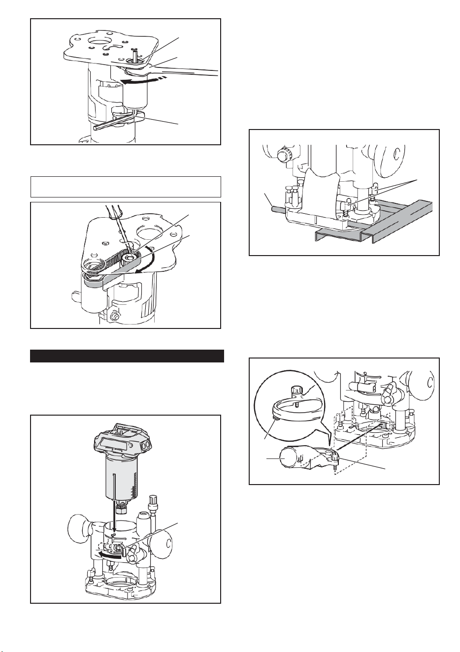
12
► 1. Lock lever
8. Attach the base plate by tightening the screws.
► 1. Collet nut 2. Wrench 3. Hex wrench
To remove the base, follow the installation procedure in reverse.
► 1. Base plate
9. Insert the collet cone and the router bit into the
offset base, and then tighten the collet nut.
► 1. Pulley 2. Belt
Installing or removing the plunge base
Optional accessory
1. Open the lock lever of the plunge base, then insert
the tool into the plunge base all the way aligning the
groove on the tool with the protrusion on the plunge base.
► 1. router bit 2. Collet nut 3. Collet cone
10. Insert the hex wrench into the hole of the offset
base, and then tighten the collet nut with the wrench.
► 1. Lock lever
1
1
2
3
1
NOTE: You can also mount the belt to the pulley with-
out removing the base plate as shown in the figure.
1
2
3
1
2
1
13
2. Close the lock lever.
To remove the base, follow the installation procedure
in reverse.
Installing or removing the parallel
ruler on the plunge base
Optional accessory
Insert the guide bars into the holes in the plunge base,
and then tighten the wing bolts. To remove the ruler,
follow the installation procedure in reverse.
OPERATION
Using the tool with the router base
► 1. Wing bolt 2. Guide bar
Installing or removing the dust
nozzle on the plunge base
Insert the dust nozzle into the plunge base so that the
protrusion on the dust nozzle fits in the notch in the
plunge base, and then tighten the thumb screw on the
dust nozzle. To remove the nozzle, follow the installa-
tion procedure in reverse.
Set the tool base on the workpiece without the router
bit making any contact. Turn the tool on and wait until
the bit attains full speed. Move the tool forward over
the workpiece surface. Keep the tool base flush while
moving the tool.
When cutting the edge, be sure to keep the workpiece
surface on the left side of the router bit in the feed
direction.
► 1. Protrusion 2. Dust nozzle 3. Thumb screw
When using the router shoe, the straight guide, or the
router guide, be sure to keep it on the right side in the
feed direction. This will help to keep it flush with the side
of the workpiece.
1
2
3
2
1
NOTE: Before cutting on the actual workpiece, it is
recommended to make a sample cut. The proper feed
speed depends on the bit size, the kind of workpiece,
and depth of cut. Moving the tool forward too fast may
cause a poor quality of cut, or damage to the bit or
motor. Moving the tool forward too slowly may burn
and mar the cut.
9
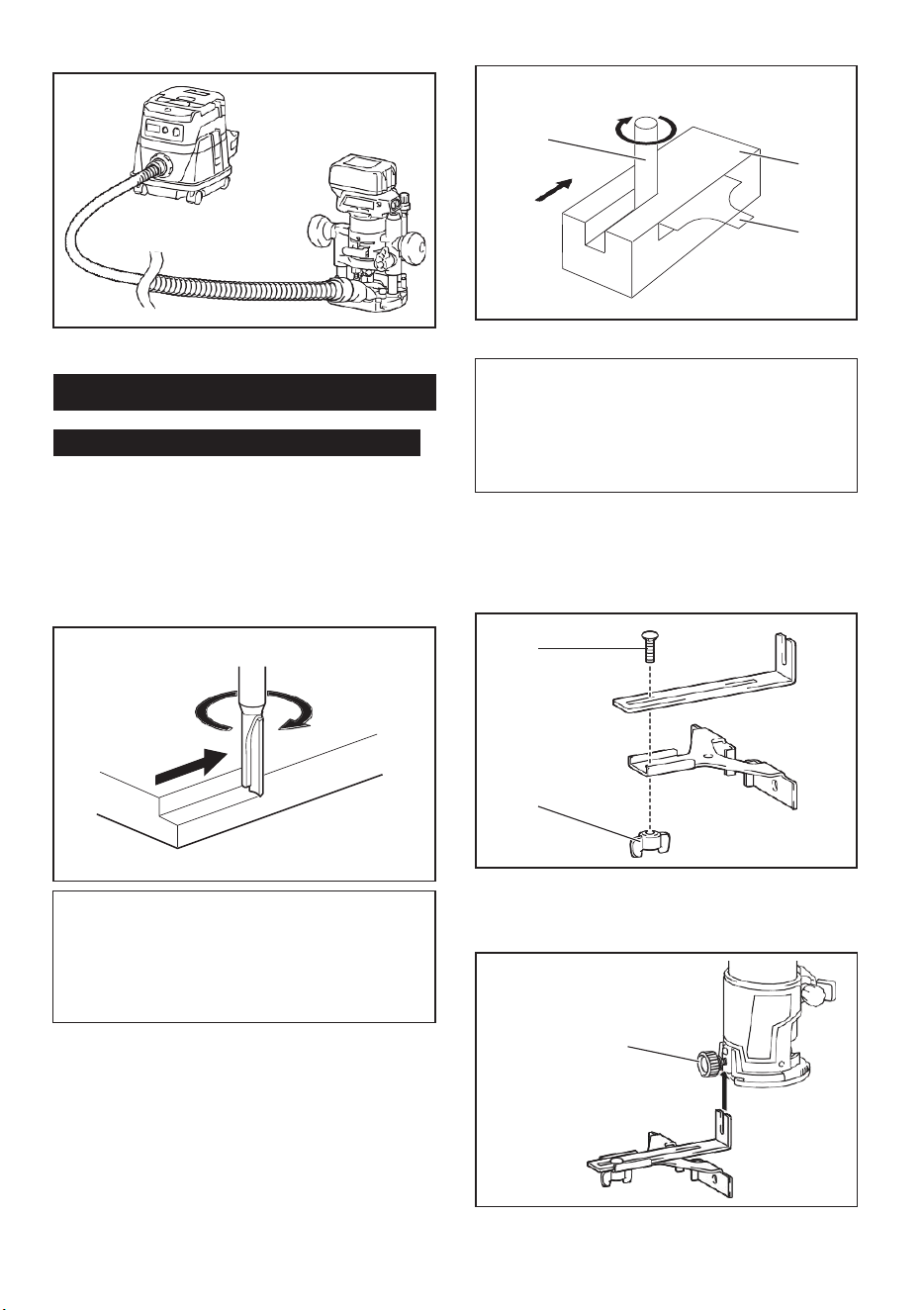
13
2. Close the lock lever.
To remove the base, follow the installation procedure
in reverse.
Installing or removing the parallel
ruler on the plunge base
Optional accessory
Insert the guide bars into the holes in the plunge base,
and then tighten the wing bolts. To remove the ruler,
follow the installation procedure in reverse.
OPERATION
Using the tool with the router base
► 1. Wing bolt 2. Guide bar
Installing or removing the dust
nozzle on the plunge base
Insert the dust nozzle into the plunge base so that the
protrusion on the dust nozzle fits in the notch in the
plunge base, and then tighten the thumb screw on the
dust nozzle. To remove the nozzle, follow the installa-
tion procedure in reverse.
Set the tool base on the workpiece without the router
bit making any contact. Turn the tool on and wait until
the bit attains full speed. Move the tool forward over
the workpiece surface. Keep the tool base flush while
moving the tool.
When cutting the edge, be sure to keep the workpiece
surface on the left side of the router bit in the feed
direction.
► 1. Protrusion 2. Dust nozzle 3. Thumb screw
When using the router shoe, the straight guide, or the
router guide, be sure to keep it on the right side in the
feed direction. This will help to keep it flush with the side
of the workpiece.
1
2
3
2
1
NOTE: Before cutting on the actual workpiece, it is
recommended to make a sample cut. The proper feed
speed depends on the bit size, the kind of workpiece,
and depth of cut. Moving the tool forward too fast may
cause a poor quality of cut, or damage to the bit or
motor. Moving the tool forward too slowly may burn
and mar the cut.
14
3. Loosen the wing nut on the straight guide and
adjust the distance between the bit and the straight
guide. At the desired distance, tighten the wing nut.
► 1. router bit 2. Workpiece 3. Straight guide
► 1. Wing nut
4. Move the tool with the straight guide flush with the
side of the workpiece.
Using the straight guide
Optional accessory
1. Assemble the straight guide with the bolt and the
wing nut.
► 1. Bolt 2. Wing nut
2. Attach the straight guide to the router base with
the clamp screw.
If the distance (A) between the side of the workpiece
and the cutting position is too wide for the straight
guide, or if the side of the workpiece is not straight, the
straight guide cannot be used.
In this case, firmly clamp a straight board to the work-
piece and use it as a guide against the router base.
Feed the tool in the direction of the arrow.
► 1. Clamp screw
1
1
2
3
1
2
1
A
NOTICE: Since excessive cutting may cause
overload of the motor or difficulty in controlling
the tool, the depth of cut should not be more than
3 mm (1/8") at a pass when cutting grooves. When
you wish to cut grooves more than 3 mm (1/8") deep,
make several passes with progressively deeper bit
settings.
10
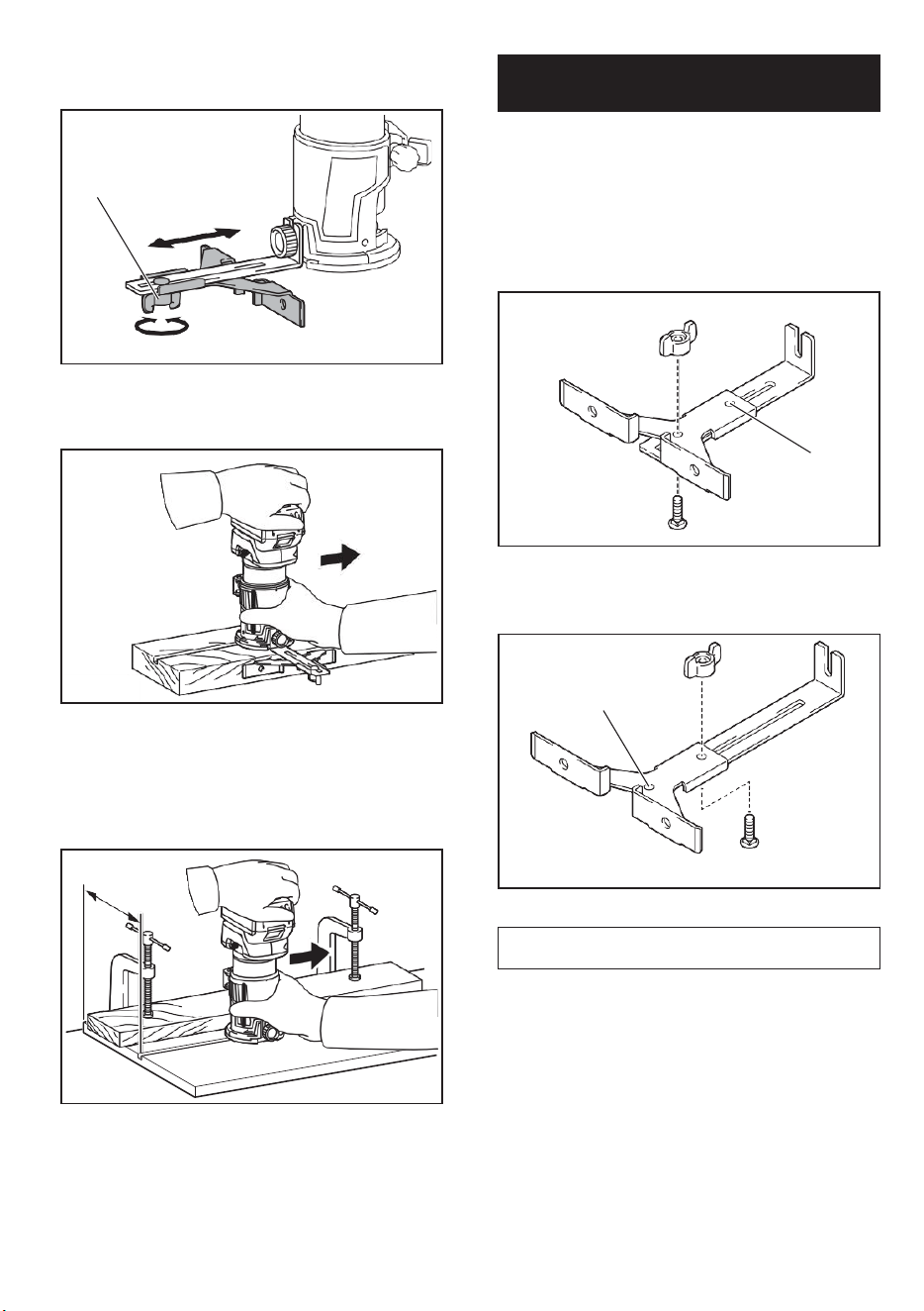
14
3. Loosen the wing nut on the straight guide and
adjust the distance between the bit and the straight
guide. At the desired distance, tighten the wing nut.
► 1. router bit 2. Workpiece 3. Straight guide
► 1. Wing nut
4. Move the tool with the straight guide flush with the
side of the workpiece.
Using the straight guide
Optional accessory
1. Assemble the straight guide with the bolt and the
wing nut.
► 1. Bolt 2. Wing nut
2. Attach the straight guide to the router base with
the clamp screw.
If the distance (A) between the side of the workpiece
and the cutting position is too wide for the straight
guide, or if the side of the workpiece is not straight, the
straight guide cannot be used.
In this case, firmly clamp a straight board to the work-
piece and use it as a guide against the router base.
Feed the tool in the direction of the arrow.
► 1. Clamp screw
1
1
2
3
1
2
1
A
NOTICE: Since excessive cutting may cause
overload of the motor or difficulty in controlling
the tool, the depth of cut should not be more than
3 mm (1/8") at a pass when cutting grooves. When
you wish to cut grooves more than 3 mm (1/8") deep,
make several passes with progressively deeper bit
settings.
15
For circular work, assemble the straight guide as shown
in the figures. The minimum and maximum radius of
circles to be cut (distance between the center of circle
and the center of bit) are as follows:
• Minimum: 70 mm (2-3/4")
• Maximum: 221 mm (8-11/16")
For cutting circles between 70 mm (2-3/4") and 121
mm (4-3/4") in radius.
► 1. Nail 2. Center hole
Using the templet guide
► 1. Center hole
For cutting circles between 121 mm (4-3/4") and 221
mm (8-11/16") in radius.
Optional accessory
The templet guide allows for repetitive cut with templet
patterns by using a templet.
1. Loosen the screws on the base plate, and then
remove the base plate from the router base.
2. Place the templet guide on the base, and then
attach the base plate by tightening the screws.
► 1. Center hole
Align the center hole in the straight guide with the
center of the circle to be cut. Drive a nail less than 6
mm (1/4") in diameter into the center hole to secure
the straight guide. Pivot the tool around the nail in the
clockwise direction.
► 1. Base plate 2. Templet guide
3. Place the tool on the templet and move the tool
with the templet guide sliding along the side of the
templet.
Using the straight guide for circular
work
1
1
1
2
1
2
NOTE: Circles between 172 mm (6-3/4") and 186 mm
(7-5/16") in radius cannot be cut using this guide.
11
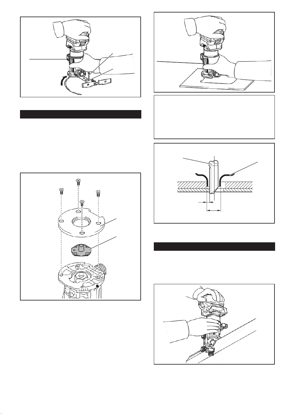
15
For circular work, assemble the straight guide as shown
in the figures. The minimum and maximum radius of
circles to be cut (distance between the center of circle
and the center of bit) are as follows:
• Minimum: 70 mm (2-3/4")
• Maximum: 221 mm (8-11/16")
For cutting circles between 70 mm (2-3/4") and 121
mm (4-3/4") in radius.
► 1. Nail 2. Center hole
Using the templet guide
► 1. Center hole
For cutting circles between 121 mm (4-3/4") and 221
mm (8-11/16") in radius.
Optional accessory
The templet guide allows for repetitive cut with templet
patterns by using a templet.
1. Loosen the screws on the base plate, and then
remove the base plate from the router base.
2. Place the templet guide on the base, and then
attach the base plate by tightening the screws.
► 1. Center hole
Align the center hole in the straight guide with the
center of the circle to be cut. Drive a nail less than 6
mm (1/4") in diameter into the center hole to secure
the straight guide. Pivot the tool around the nail in the
clockwise direction.
► 1. Base plate 2. Templet guide
3. Place the tool on the templet and move the tool
with the templet guide sliding along the side of the
templet.
Using the straight guide for circular
work
1
1
1
2
1
2
NOTE: Circles between 172 mm (6-3/4") and 186 mm
(7-5/16") in radius cannot be cut using this guide.
16
► 1. Clamp screw
2. Loosen the clamp screw and adjust the distance
between the router bit and the router guide by turn- ing
the adjusting screw (1 mm (3/64") per turn). At the
desired distance, tighten the clamp screw to secure the
router guide.
► 1. router bit 2. Templet guide 3. Distance (X)
4. Outside diameter of templet guide
Using the router guide
Optional accessory
The router guide allows for trimming curved side like
veneers for furniture by moving the guide roller along
the side of the workpiece.
► 1. Adjusting screw 2. Clamp screw
3. Move the tool with the guide roller riding the side
of the workpiece.
► 1. Workpiece 2. Bit 3. Guide roller
z
1. Loosen the clamp screw, then install the router
guide on the router base, and then tighten the clamp
screw
1
1
2
1
2
3
4
1
2
3
NOTE: The actual cut size on the workpiece is slightly
different from the templet. The difference is the dis-
tance (X) between the router bit and the outside of the
templet guide. The distance (X) can be calculated by
using the following equation:
Distance (X) = (outside diameter of templet guide -
router bit diameter) / 2
12
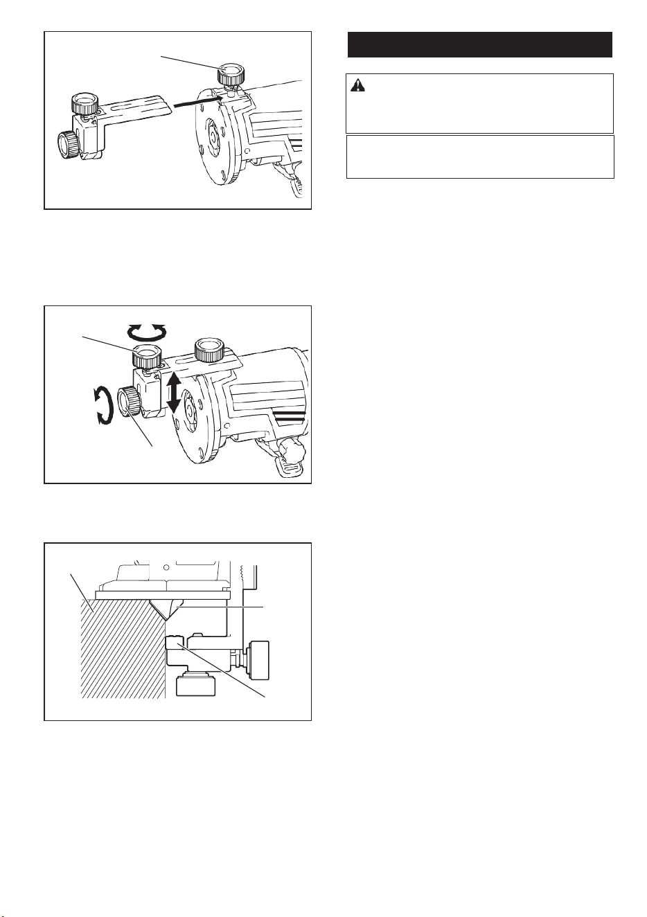
16
► 1. Clamp screw
2. Loosen the clamp screw and adjust the distance
between the router bit and the router guide by turn- ing
the adjusting screw (1 mm (3/64") per turn). At the
desired distance, tighten the clamp screw to secure the
router guide.
► 1. router bit 2. Templet guide 3. Distance (X)
4. Outside diameter of templet guide
Using the router guide
Optional accessory
The router guide allows for trimming curved side like
veneers for furniture by moving the guide roller along
the side of the workpiece.
► 1. Adjusting screw 2. Clamp screw
3. Move the tool with the guide roller riding the side
of the workpiece.
► 1. Workpiece 2. Bit 3. Guide roller
z
1. Loosen the clamp screw, then install the router
guide on the router base, and then tighten the clamp
screw
1
1
2
1
2
3
4
1
2
3
NOTE: The actual cut size on the workpiece is slightly
different from the templet. The difference is the dis-
tance (X) between the router bit and the outside of the
templet guide. The distance (X) can be calculated by
using the following equation:
Distance (X) = (outside diameter of templet guide -
router bit diameter) / 2
17
MAINTENANCE
To maintain product SAFETY and RELIABILITY, repairs, any other maintenance or adjustment should be performed
by Authorized or Factory Service Centers, always using original replacement
NOTICE:
Never use gasoline, benzine, thinner,
alcohol or the like. Discoloration, deformation or
cracks may result.
CAUTION: Always be sure that the tool is
switched off and the battery cartridge is removed
before attempting to perform inspection or
maintenance.
To maintain product SAFETY and RELIABILITY, repairs,
any other maintenance or adjustment should be
performed by Authorized or Factory Service Centers,
always using original replacement.
17
MAINTENANCE
To maintain product SAFETY and RELIABILITY, repairs, any other maintenance or adjustment should be performed
by Authorized or Factory Service Centers, always using original replacement
NOTICE: Never use gasoline, benzine, thinner,
alcohol or the like. Discoloration, deformation or
cracks may result.
CAUTION: Always be sure that the tool is
switched off and the battery cartridge is removed
before attempting to perform inspection or
maintenance.
13