
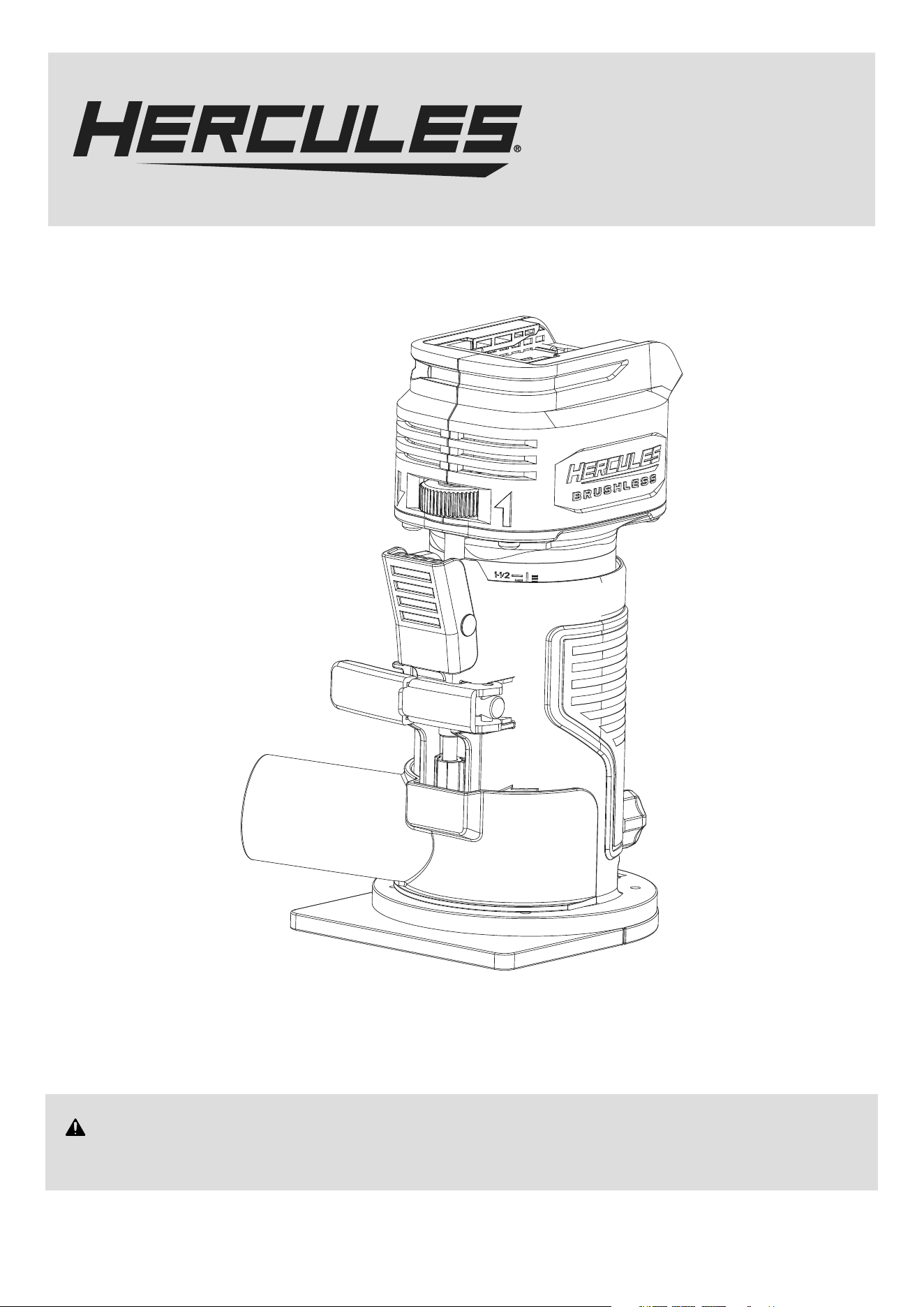
Model
HCB043
20V Brushless Compact Router
WARNING: To prevent serious injury, User must read and
understand Owner’s Manual. SAVE THIS MANUAL.
When unpacking, make sure that the product is intact and undamaged.
If any parts are missing or broken, please call 1-888-866-5797
as soon as possible. Reference 59615.
Owner’s Manual &
Safety Instructions
Battery and Charger Sold Separately

Page 2 For technical questions, please call 1-888-866-5797. Item 59615
IMPORTANT SAFETY INFORMATION
General Power Tool Safety Warnings
Read all safety warnings, instructions, illustrations
and specifications provided with this power tool.
Failure to follow all instructions listed below may r
esult in electric shock, fire and/or serious injury.
Save all warnings and instructions
for future reference.
The term “power tool” in the warnings refers
to your mains-operated (corded) power tool or
battery-operated (cordless) power tool.
Work area safety
1. Keep work area clean and well lit.
Cluttered or dark areas invite accidents.
2. Do not operate power tools in explosive
atmospheres, such as in the presence of
flammable liquids, gases or dust. Power tools
create sparks which may ignite the dust or fumes.
3. Keep children and bystanders away
while operating a power tool. Distractions
can cause you to lose control.
Electrical safety
1. Power tool plugs must match the outlet.
Never modify the plug in any way. Do not use
any adapter plugs with earthed (grounded)
power tools. Unmodified plugs and matching
outlets will reduce risk of electric shock.
2. Avoid body contact with earthed or grounded
surfaces, such as pipes, radiators, ranges and
refrigerators. There is an increased risk of electric
shock if your body is earthed or grounded.
3. Do not expose power tools to rain or wet
conditions. Water entering a power tool
will increase the risk of electric shock.
4. Do not abuse the cord. Never use the cord
for carrying, pulling or unplugging the power
tool. Keep cord away from heat, oil, sharp
edges or moving parts. Damaged or entangled
cords increase the risk of electric shock.
5. When operating a power tool outdoors,
use an extension cord suitable for outdoor
use. Use of a cord suitable for outdoor
use reduces the risk of electric shock.
6. If operating a power tool in a damp location
is unavoidable, use a ground fault circuit
interrupter (GFCI) protected supply. Use of
a GFCI reduces the risk of electric shock.
Personal safety
1. Stay alert, watch what you are doing and use
common sense when operating a power tool.
Do not use a power tool while you are tired
or under the influence of drugs, alcohol or
medication. A moment of inattention while operating
power tools may result in serious personal injury.
2. Use personal protective equipment. Always
wear eye protection. Protective equipment
such as dust mask, non-skid safety shoes, hard
hat, or hearing protection used for appropriate
conditions will reduce personal injuries.
3. Prevent unintentional starting. Ensure the
switch is in the off-position before connecting
to power source and/or battery pack, picking
up or carrying the tool. Carrying power tools
with your finger on the switch or energizing power
tools that have the switch on invites accidents.
4. Remove any adjusting key or wrench
before turning the power tool on. A wrench
or a key left attached to a rotating part of the
power tool may result in personal injury.
5. Do not overreach. Keep proper footing and
balance at all times. This enables better control
of the power tool in unexpected situations.
6. Dress properly. Do not wear loose clothing or
jewelry. Keep your hair, clothing and gloves
away from moving parts. Loose clothes, jewelry
or long hair can be caught in moving parts.
7. If devices are provided for the connection of
dust extraction and collection facilities, ensure
these are connected and properly used. Use of
dust collection can reduce dust-related hazards.
8. Do not let familiarity gained from frequent use
of tools allow you to become complacent and
ignore tool safety principles. A careless action can
cause severe injury within a fraction of a second.
9. Only use safety equipment that has been
approved by an appropriate standards agency.
Unapproved safety equipment may not provide
adequate protection. Eye protection must be
ANSI-approved and breathing protection
must be NIOSH-approved for the
specific hazards in the work area.
10. Avoid unintentional starting. Prepare to
begin work before turning on the tool.
11. Do not lay the tool down until it has come to
a complete stop. Moving parts can grab the
surface and pull the tool out of your control.
12. When using a handheld power tool,
maintain a firm grip on the tool with
both hands to resist starting torque.
13. Do not depress the spindle lock when
starting or during operation.

Page 3For technical questions, please call 1-888-866-5797.Item 59615
14. Do not leave the tool unattended when the
Battery Pack is connected. Turn off the tool,
and remove the Battery Pack before leaving.
15. This product is not a toy.
Keep it out of reach of children.
16. People with pacemakers should consult their
physician(s) before use. Electromagnetic fields
in close proximity to heart pacemaker could cause
pacemaker interference or pacemaker failure.
17. The warnings, precautions, and instructions
discussed in this instruction manual cannot
cover all possible conditions and situations
that may occur. It must be understood by the
operator that common sense and caution are
factors which cannot be built into this product,
but must be supplied by the operator.
Power tool use and care
1. Do not force the power tool. Use the correct
power tool for your application. The correct
power tool will do the job better and safer
at the rate for which it was designed.
2. Do not use the power tool if the Trigger
does not turn it on and off. Any power tool
that cannot be controlled with the Trigger
is dangerous and must be repaired.
3. Disconnect the plug from the power source and/
or remove the battery pack, if detachable, from
the power tool before making any adjustments,
changing accessories, or storing power
tools. Such preventive safety measures reduce
the risk of starting the power tool accidentally.
4. Store idle power tools out of the reach of
children and do not allow persons unfamiliar
with the power tool or these instructions
to operate the power tool. Power tools are
dangerous in the hands of untrained users.
5. Maintain power tools and accessories.
Check for misalignment or binding of moving
parts, breakage of parts and any other
condition that may affect the power tool’s
operation. If damaged, have the power tool
repaired before use. Many accidents are
caused by poorly maintained power tools.
6. Keep cutting tools sharp and clean. Properly
maintained cutting tools with sharp cutting edges
are less likely to bind and are easier to control.
7. Use the power tool, accessories and tool bits
etc. in accordance with these instructions,
taking into account the working conditions
and the work to be performed. Use of the
power tool for operations different from those
intended could result in a hazardous situation.
8. Keep handles and grasping surfaces dry, clean
and free from oil and grease. Slippery handles
and grasping surfaces do not allow for safe handling
and control of the tool in unexpected situations.
Service
1. Have your power tool serviced by a
qualified repair person using only identical
replacement parts. This will ensure that the
safety of the power tool is maintained.
2. Never service damaged BATTERY packs. Service
of BATTERY packs should only be performed by
the manufacturer or authorized service providers.
3. Maintain labels and nameplates on the tool.
These carry important safety information.
If unreadable or missing, contact
Harbor Freight Tools for a replacement.
Battery tool use and care
1. Prevent unintentional starting. Ensure the switch is
in the off-position before connecting to battery pack,
picking up or carrying the power tool. Carrying the
power tool with your finger on the switch or energizing
power tool that have the switch on invites accidents.
2. Disconnect the battery pack from the
power tool before making any adjustments,
changing accessories, or storing power tool.
Such preventive safety measures reduce the
risk of starting the power tool accidentally.
3. Recharge only with the charger specified by
the manufacturer. A charger that is suitable
for one type of battery pack may create a risk
of fire when used with another battery pack.
4. Use power tools only with specifically
designated battery packs. Use of any other
battery packs may create a risk of injury and fire.
5. When battery pack is not in use, keep it away
from other metal objects, like paper clips,
coins, keys, nails, screws or other small metal
objects, that can make a connection from
one terminal to another. Shorting the battery
terminals together may cause burns or a fire.
6. Under abusive conditions, liquid may be ejected
from the battery; avoid contact. If contact
accidentally occurs, flush with water. If liquid contacts
eyes, additionally seek medical help. Liquid ejected
from the battery may cause irritation or burns.
7. Do not use a battery pack or power tool that
is damaged or modified. Damaged or modified
batteries may exhibit unpredictable behavior
resulting in fire, explosion or risk of injury.
8. Do not expose a battery pack or power tool to
fire or excessive temperature. Exposure to fire or
temperature above 140°F may cause explosion.

Page 4 For technical questions, please call 1-888-866-5797. Item 59615
9. Follow all charging instructions and do
not charge the battery pack or power tool
outside of the temperature range specified
in the instructions. Charging improperly or at
temperatures outside of the specified range may
damage the battery and increase the risk of fire.
10. Have servicing performed by a qualified
repair person using only identical
replacement parts. This will ensure that
the safety of the product is maintained.
11. Do not modify or attempt to repair the power
tool or the battery pack except as indicated
in the instructions for use and care.
12. The battery Charger gets hot during
use. The Charger’s heat can build up to
unsafe levels and create a fire hazard if it
does not receive adequate ventilation, due
to an electrical fault, or if it is used in a
hot environment. Do not place the Charger on a
flammable surface. Do not obstruct any vents on the
Charger. Especially avoid placing the Charger on
carpets and rugs; they are not only flammable,
but they also obstruct vents under the Charger.
Place the Charger on a stable, solid, nonflammable
surface (such as a stable metal workbench or
concrete floor) at least 1 foot away from all flammable
objects, such as drapes or walls. Keep a fire
extinguisher and a smoke detector in the area.
Frequently monitor the Charger and
Battery Pack while charging.
Safety instructions for routers
1. Hold power tool by insulated gripping surfaces,
because the cutter may contact its own cord.
Cutting a ″live″ wire may make exposed metal parts
of the power tool ″live″ and shock the operator.
2. Use clamps or another practical way to secure
and support the workpiece to a stable platform.
Holding the work by hand or against your body
leaves it unstable and may lead to loss of control.
3. Let bit cool before touching, changing
or adjusting it. Bits heat up dramatically
while in use, and can burn you.
4. Verify that the work surface has no
hidden utility lines before cutting.
Lithium Battery Safety Warnings
LITHIUM BATTERIES STORE
A LARGE AMOUNT OF ENERGY AND
WILL VENT FIRE OR EXPLODE
IF MISTREATED:
1. Keep Battery Pack dry.
2. DO NOT DO ANY OF THE FOLLOWING
TO THE BATTERY PACK:
• Open,
• Drop,
• Short-circuit,
• Puncture,
• Incinerate, or
• Expose to temperatures greater than 140°F.
3. Charge Battery Pack only according
to its Charger’s instructions.
4. Inspect Battery Pack before every use;
do not use or charge if damaged.
Vibration Safety
This tool vibrates during use.
Repeated or long-term exposure to vibration may
cause temporary or permanent physical injury,
particularly to the hands, arms and shoulders.
To reduce the risk of vibration-related injury:
1. Anyone using vibrating tools regularly or for an
extended period should first be examined by a
doctor and then have regular medical check-ups
to ensure medical problems are not being caused
or worsened from use. Pregnant women or people
who have impaired blood circulation to the hand, past
hand injuries, nervous system disorders, diabetes,
or Raynaud’s Disease should not use this tool.
If you feel any symptoms related to vibration (such
as tingling, numbness, and white or blue fingers),
seek medical advice as soon as possible.
2. Do not smoke during use. Nicotine reduces
the blood supply to the hands and fingers,
increasing the risk of vibration-related injury.
3. Wear suitable gloves to reduce the
vibration effects on the user.
4. Use tools with the lowest vibration
when there is a choice.
5. Include vibration-free periods each day of work.
6. Grip tool as lightly as possible (while still keeping
safe control of it). Let the tool do the work.
7. To reduce vibration, maintain the tool as
explained in this manual. If any abnormal
vibration occurs, stop use immediately.
Page 5For technical questions, please call 1-888-866-5797.Item 59615
Grounding
Note: Extension cords must not be
used with this item’s Charger.
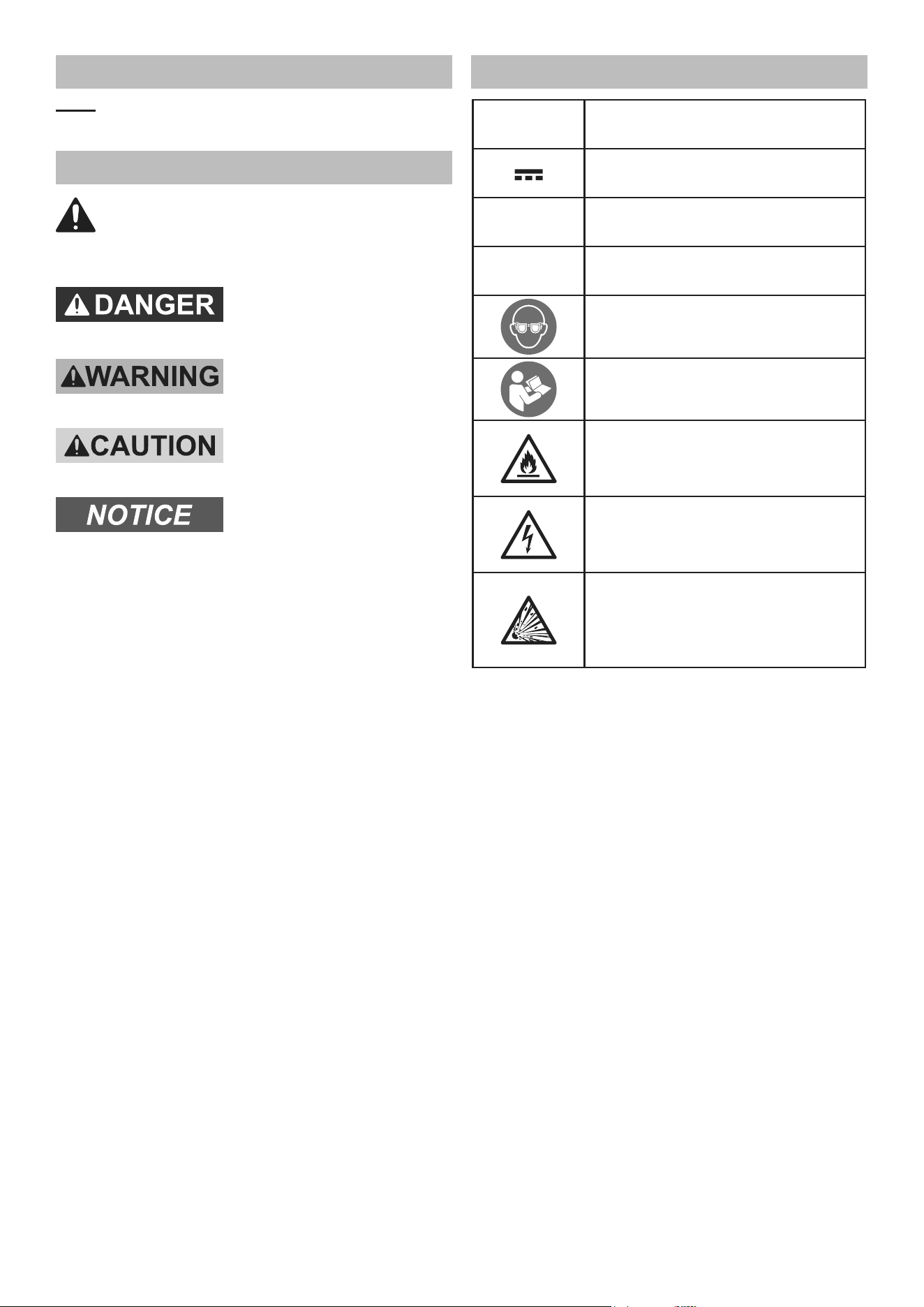
Warning Symbols and Definitions
This is the safety alert symbol. It is used to
alert you to potential personal injury hazards.
Obey all safety messages that follow this symbol to
avoid possible injury or death.
Indicates a hazardous
situation which, if not
avoided, will result in death or serious injury.
Indicates a hazardous
situation which, if not
avoided, could result in death or serious injury.
Indicates a hazardous
situation which, if not
avoided, could result in minor or moderate injury.
Addresses practices not
related to personal injury.
Symbology
V
Volts
Direct Current
A
Amperes
n
0
xxxx/min.
No Load Revolutions per Minute (RPM)
WARNING marking concerning Risk
of Eye Injury. Wear ANSI-approved
safety goggles with side shields.
Read the manual before set-up and/or use.
WARNING marking
concerning Risk of Fire.
Do not cover Charger ventilation ducts.
Charge on fireproof surface only.
WARNING marking concerning
Risk of Electric Shock.
Properly connect Charger’s power
cord to appropriate outlet.
WARNING marking concerning
Risk of Explosion.
Do not puncture, short, or open
battery packs and do not charge
damaged battery packs.
Page 6 For technical questions, please call 1-888-866-5797. Item 59615
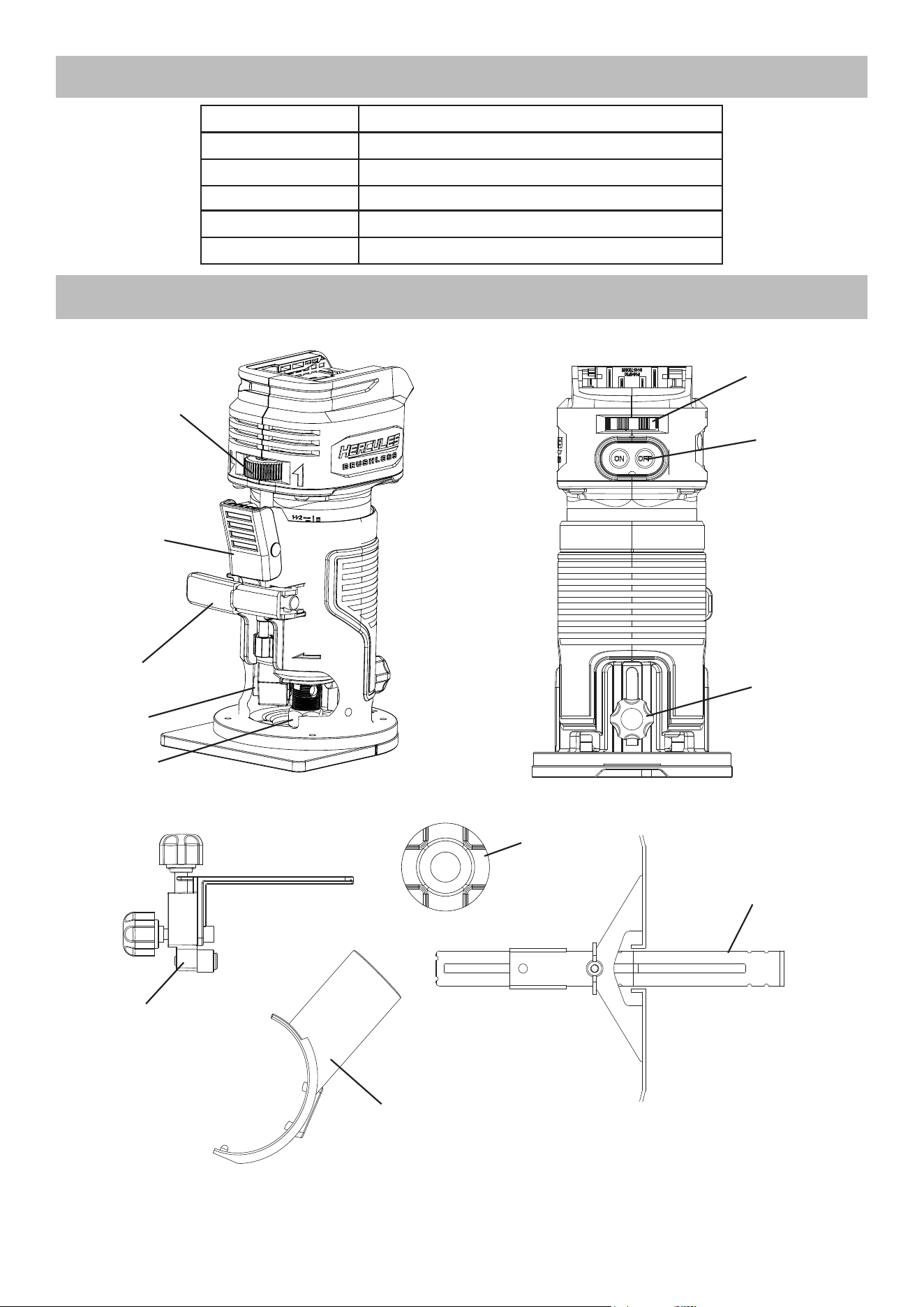
SPECIFICATIONS
Battery Type Hercules 20 V Li-ion 57373 (sold separately)
Charger Type Hercules 20V/12V Li-ion 56559 (sold separately)
Electrical Rating 20VDC
No Load Speed n
0
: 10000 - 30000/min
Collet Size 1/4" Shank Diameter
Max. Plunge Depth 1-1/2″
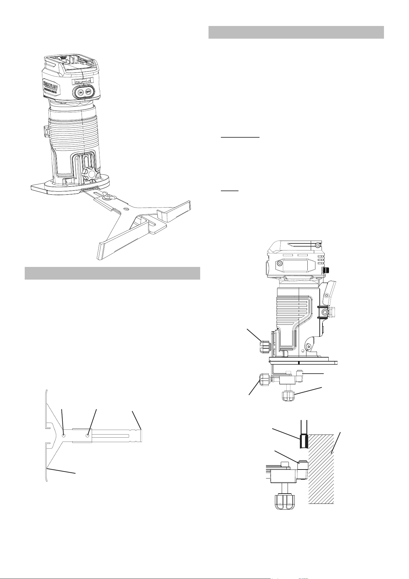
FUNCTIONAL DESCRIPTION
Fine Depth
Adjustment
Quick Release
Lever
Locking
Lever
Spindle
Lock
Collet
Assembly
Speed
Control Dial
Power
On / Off
Guide
Locking Knob
Dust
Port
Roller Guide
Edge Guide
Template
Guide
Page 7For technical questions, please call 1-888-866-5797.Item 59615
SETUP - BEFORE USE
Read the ENTIRE IMPORTANT SAFETY
INFORMATION section at the beginning of
this manual including all text under
subheadings therein before set up or use
.
TO PREVENT SERIOUS INJURY FROM ACCIDENTAL
OPERATION: Turn Power “OFF” and remove the
Battery Pack before performing any procedure in
this section.
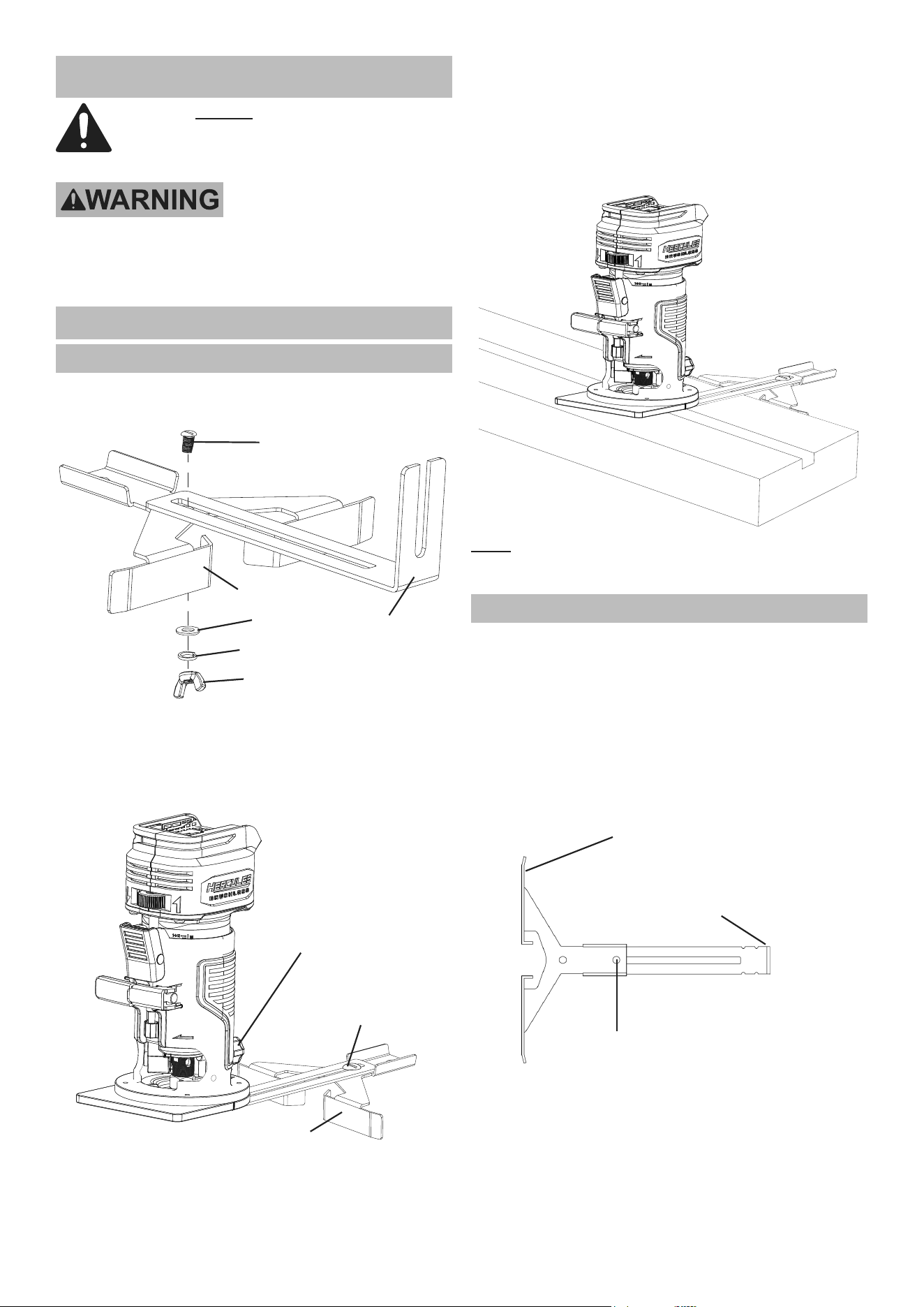
Assembly
Edge Guide Installation
1. Assemble the Edge Guide using the locking screw
and wing nut with its washer and lock washer.
Guide Bracket
Edge Guide
Locking Screw
Washer
Wing Nut
Lock Washer
2. Loosen the Guide Locking Knob. The short
end of the Edge Guide should slide underneath
the Guide Locking Knob. Align the Edge Guide
to the mounting position of the Base Plate
and insert it to the desired working height.
Guide
Locking Knob
Edge Guide
Edge Guide
Depth Adjustment
3. Secure the Edge Guide in position by tightening
the Guide Locking Knob clockwise.
4. To adjust the Edge Guide:
a. Loosen the Edge Guide Wing
Nut counterclockwise.
b. Slide the Edge Guide to desired working position.
c. Retighten the Wing Nut to secure the Edge Guide.
5. Align the Edge Guide along the material to be
routed to cut parallel with the workpiece edge.
Note: The Edge Guide may be used for circle
cutting by turning the Edge Guide over and using the
center gap in the Edge Guide to follow the circle.
Temporary Guide Installation
A temporary guide can be used to make a straight cut
which does not parallel the edge of the workpiece.
1. Clamp a suitable straight board across the workpiece
parallel to the desired location of the cut.
2. Install the Edge Guide Assembly with the
Edge Guide facing outward and up. The Wing
Nut should be installed in the hole furthest
from the raised edge of the Edge Guide.
Raised Edge of Parallel Guide
(Outward and Up)
Attach Wing Nut
Raised Edge of
Parallel Guide Bracket
(Attached to Router)
Page 8 For technical questions, please call 1-888-866-5797. Item 59615
3. Align the Edge Guide along the temporary
guide secured to the workpiece to cut
parallel with the temporary guide.
Circle Cutting Installation
1. Install the Edge Guide as shown.
2. Set the distance from the center hole in the Edge
Guide to the far edge of the router bit equal to the
radius of the circle. Lock the Edge Guide in place
with the Guide Locking Knob and Wing Nut.
3. Align the center gap in the Edge Guide
with the center point of the circle.
4. Drive a nail through the center hole to
secure the Edge Guide in place.
5. Use the nail in the center to rotate the
Router and make a circle cut.
Raised Edge of
Parallel Guide
(Attached to Router)
Center
Hole
Attach
Wing Nut
Raised Edge of Parallel Guide
(Outward and Up)
Roller Guide Installation
The Roller Guide trims in relation to both the workpiece’s
top surface and its edge surface. The Router must
be adjusted to cut accurately in two dimensions.
1. Assemble the Roller Guide as shown.
Attach to the Router Base.
2. Adjust the Router Base so the cutting
depth will be flush with the surface that
you will be trimming to match.
3. Loosen the Guide Locking Knob and adjust
the Roller Guide so that its Roller Wheel is
below the bit by approximately 3/4″ to 1″. Tighten
it in position using the Guide Locking Knob.
4. Center the cutting bit over the edge to be
trimmed by loosening the Roller Guide Locking
Knob and sliding the Roller Wheel into position.
Tighten the Roller Guide Locking Knob.
Note: To make fine adjustments, partially loosen
Roller Guide Locking Knob and use the Roller
Guide Fine Adjustment. When the adjustments are
finalized, tighten the Roller Guide Locking Knob.
5. Make a test cut on a piece of scrap material
to ensure that the adjustment is correct.
Guide
Locking Knob
Roller Guide
Fine Adjustment
Roller Wheel
Roller Guide
Locking Knob
Router Bit
Roller Wheel
Workpiece
Page 9For technical questions, please call 1-888-866-5797.Item 59615
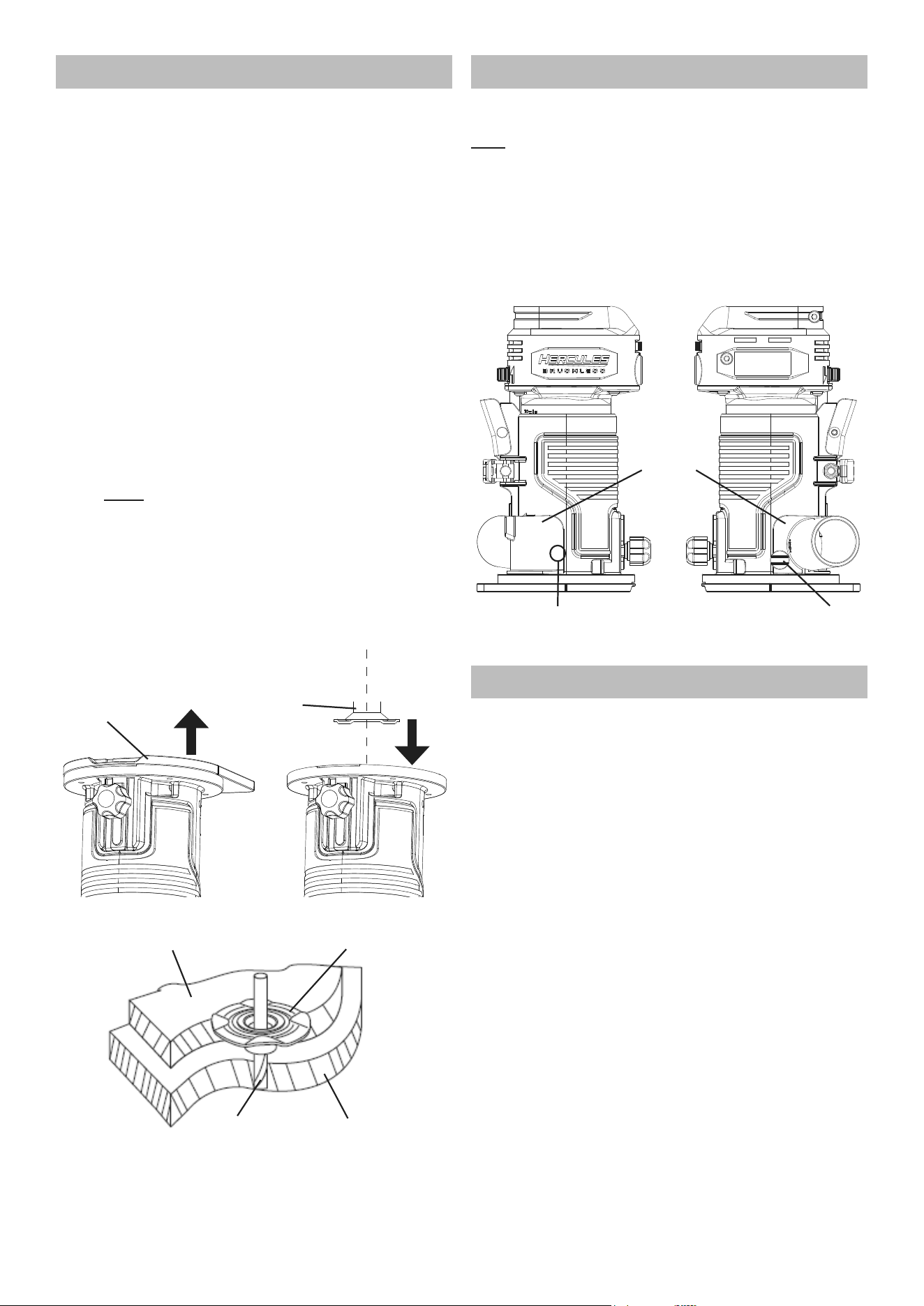
Template Guide Installation
NOTICE! The Template Guide is for use
with a template on the workpiece only.
Remove the Template Guide when using
this product for any other application.
1. Remove the four screws from the bottom of
the Sub-Base, then remove the Sub-Base.
2. Place the Template Guide in the opening of the
Base with its collar facing away from the Base.
3. Reassemble the Sub-Base to the
Base with its four screws.
4. Secure the template to the workpiece:
a. Determine the template offset by subtracting
the Router Bit diameter from the Template
Guide outside diameter and divide by two.
Example: Template Guide outside diameter
is 5/8", minus the Router Bit diameter of 3/8"
equals 1/4", divide by two equals 1/8" offset.
b. Secure the template to the workpiece using the
appropriate offset from the desired cut line.
Note: If clamps are used to secure
the workpiece, make sure they do not
interfere with the Router while cutting.
5. Place the Router on the template with the collar
of the Template Guide against the edge of the
template. Apply light pressure to keep the
Template Guide flat against the template edge.
Cut the material along the desired cut line.
Sub-Base
Template
Guide
1
2
Template
Guide
Template
Workpiece
Router Bit
Dust Port Installation
The Router is supplied with a Dust Port
to connect to a dust collector.
Note The Dust Port has a raised bump on one side,
and a hole for a Thumb Screw on the other side.
1. Insert the Dust Port’s raised bump into
the hole on the outer housing.
2. Insert the Thumb Screw into the other hole
and secure the Dust Port to the Router.
3. Make sure Dust Port is secure
before using the router.
Dust
Port
Thumb
Screw
Raised Bump
(Inner Side of Dust Port)
Battery Charging
Charge battery after unpacking and before using the tool.
Follow instructions included with the battery charger.
Page 10 For technical questions, please call 1-888-866-5797. Item 59615
OPERATION
Read the ENTIRE IMPORTANT SAFETY
INFORMATION section at the beginning of
this manual including all text under
subheadings therein before set up or use
.
Tool Changing
Router Bit Installation
WARNING! TO PREVENT SERIOUS INJURY:
Use only rotary cutting bits of the correct shank
diameter for the collet mounted. Use only rotary
cutting bits suitable for the speed of the tool.
WARNING! TO PREVENT SERIOUS INJURY:
Carefully inspect cutting bits for cracks, chips, or
other damage before installing. Do not use bits
that have been dropped, cracked, or damaged.
The bit may shatter causing serious injury.
1. Use only bits with 1/4″ shank size.
2. Use only bits that are marked as suitable
for the type of material being cut.
3. Use only bits that are marked with a speed equal
or higher than the speed marked on the tool.
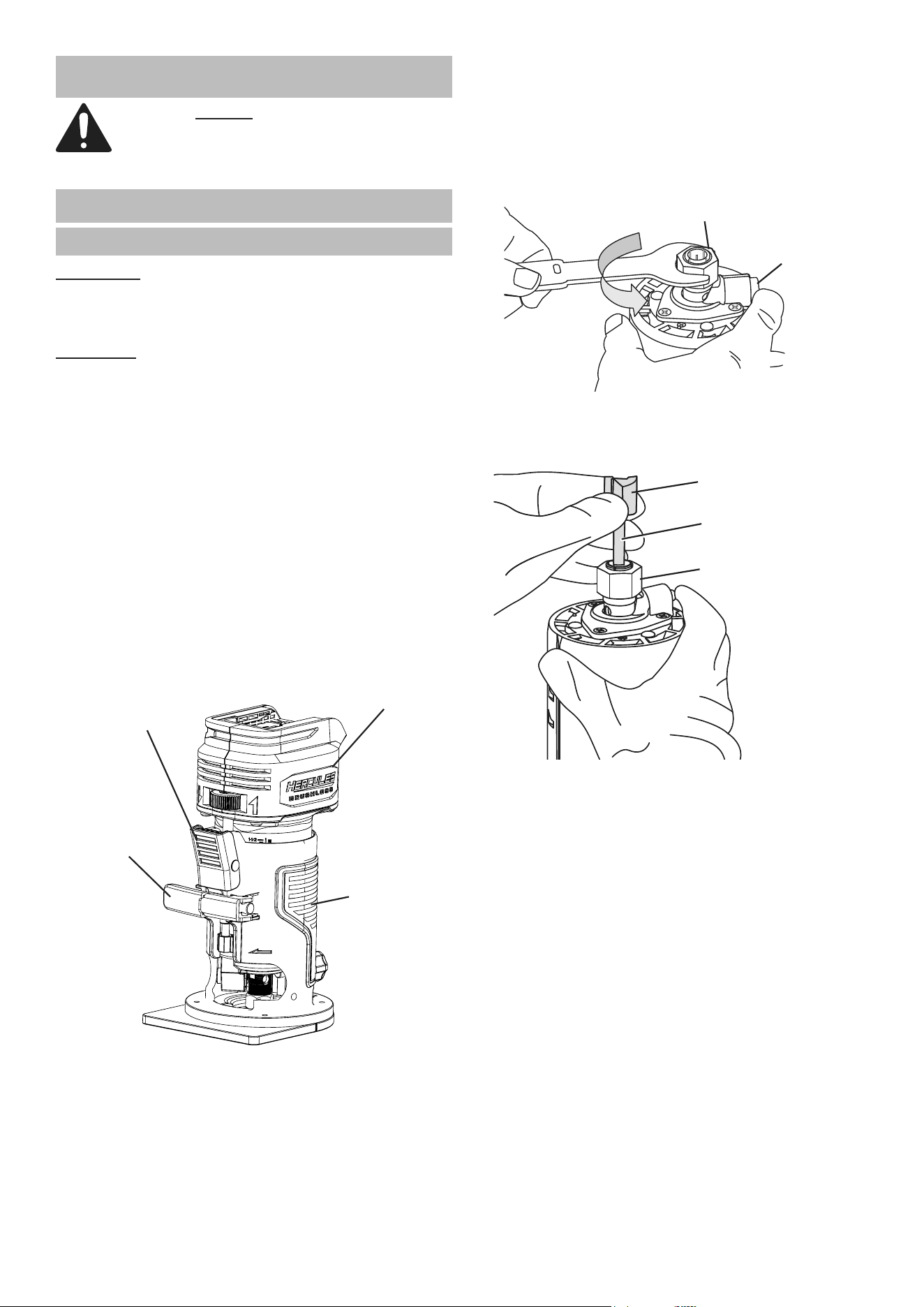
4. Open the Locking Lever.
5. Push and hold the Quick Release Lever.
6. Hold the Router Housing carefully,
move the Motor Housing upwards and
remove it from the Router Housing.
Motor
Housing
Quick Release
Lever
Locking
Lever
Router
Housing
7. Place the Motor Housing upside down on its
top with the Collet Assembly pointing up.
8. Rotate the Spindle and press the Spindle
Lock until it engages, and hold to
prevent the Spindle from rotating.
9. Loosen the Collet Assembly counterclockwise
with the included Wrench, but do not remove.
Collet Assembly
Spindle
Lock
10. Insert at least 3/4 of the shank end of
the new router bit (sold separately) into
the opening in the Collet Assembly.
Router Bit
Bit Shank
Collet Assembly
11. While still holding the Spindle Lock, tighten the
Collet Assembly. Make sure Collet Assembly
is secure before using the Router.
12. Release the Spindle Lock and confirm
the Spindle can rotate freely.
Page 11For technical questions, please call 1-888-866-5797.Item 59615
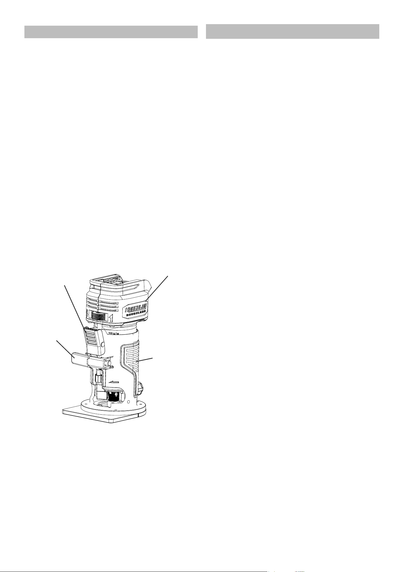
Adjusting Cutting Depth
1. Open the Locking Lever.
2. Push and hold the Quick Release Lever.
3. Hold the Router Housing carefully, slowly
move the Motor Housing upwards or
downwards to desired position.
4. Release Quick Release Lever when
Router is in desired position.
5. Further adjustments to Router Position can be
made by moving the Fine Depth Adjustment
Wheel left or right. Router Bit should just
barely touch the surface of the workpiece.
6. When Router is in the desired position,
close the Locking Lever.
7. The depth scale on the Motor Housing now
shows the starting position. This starting
position will vary depending on the bit used.
8. Add the desired depth of cut to the starting
position. For example, if the starting position
is 1/2″ and the desired depth of cut is 1/4″, the
correct adjustment on the scale is 3/4″.
9. Release the Locking Lever, and adjust the
Motor Housing until the correct reading is
shown on the depth scale; in this example
3/4″. Tighten the Locking Lever.
Motor
Housing
Quick Release
Lever
Locking
Lever
Router
Housing
Workpiece and Work Area Set Up
1. Designate a work area that is clean and well-lit.
The work area must not allow access by children
or pets to prevent distraction and injury.
2. Secure loose workpieces using a vise or clamps
(not included) to prevent movement while working.
3. Confirm the workpiece is free of any
obstacles (nails, screws, etc.,) before
operation. Remove them if required.
4. Verify that there are no utility lines or
hardware in or near the workpiece.
Page 12 For technical questions, please call 1-888-866-5797. Item 59615
General Operation
WARNING! TO PREVENT SERIOUS INJURY:
During operation, fine dust will be generated.
Wear NIOSH-approved breathing protection.
1. Confirm the Collet is tight on the router bit and
the Locking Lever is in the locked position.
2. Place the Router on the workpiece, making sure
the router bit is not in contact with the workpiece.
3. Hold the tool by gripping the textured surface
opposite the Locking Lever. Use another hand
on top of the battery pack to maintain control.
4. Adjust Router speed to suit workpiece and
router bit diameter. To adjust speed, rotate the
Variable Speed Control. Speed ranges from
1 (slowest speed) to 6 (fastest speed).
a. Generally, use the lower settings for larger
diameter cutting bits and the higher settings
for smaller cutting bits. The correct setting will
also depend on the density of the material,
depth of cut, and feed speed of the Router.
Material Speed Ranges
Hardwood 4-6
Softwood 5-6
Chipboard 3-5
Plastic 2-3
Aluminum 1-4
5. Press and hold the “ON” Power Button
for one second or until Router starts.
Note: Momentarily pressing the “ON” Power
Button will switch on the LED lights.
6. Wait until the router bit has reached its full speed
before making contact with the workpiece.
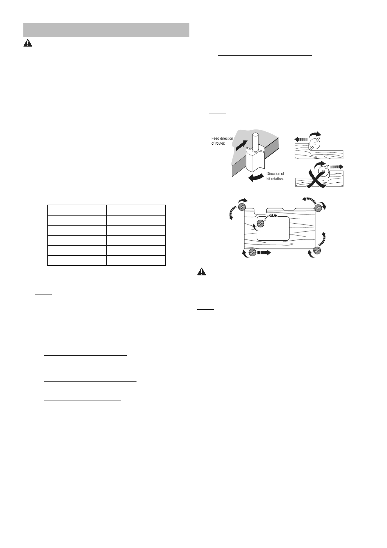
7. Move the Router with a slow, controlled motion.
Pay attention to the direction of feed. Do not force
the Router into the cut; let the cutter do the work.
a. When using the Edge Guide: Cut parallel
to the edge of the workpiece with the
Edge Guide following the edge.
b. When using a Temporary Guide: Cut with the Edge
Guide following the edge of the temporary guide.
c. When making a Circle Cut: With the nail in place
through the center hole of the Edge Guide,
plunge the router bit into the workpiece and
rotate the Router in a circle around the nail.
d. When using the Roller Guide: Cut the edge
of the workpiece with the Roller Guide
following the edge of the workpiece.
e. When using the Template Guide: Cut the
edge of the workpiece with the Template
Guide following the edge of the template.
8. Always route against the rotation direction of the
router bit. Move the Router counterclockwise when
routing on workpiece edges, move the Router
clockwise when routing the inside of the workpiece.
Note: An engraved arrow on the side of the Router
Base indicates the router bit’s direction of rotation.
WARNING! TO PREVENT SERIOUS INJURY:
Make sure the Router lays flat on the workpiece
during operation! Do not try to make cuts
with the router held only by one hand!
Note: Keep the Router moving at all times; do not stop
in one position or use too slow of a feed rate to avoid
burning the workpiece. Avoid aggressive feed rates that
slow down / overload the motor extensively.
Use several passes to achieve the desired depth; limit
cutting passes to approximately 1/8″ (3mm) depth.
9. Bring the Router to a stop at the end of the cut.
Press the “OFF” Power Button. Wait until the
router bit has come to a complete stop before
removing the Router from the workpiece.
10. To prevent accidents, turn off the tool and
remove its Battery Pack after use. Clean, then
store the tool indoors out of children’s reach

Page 13For technical questions, please call 1-888-866-5797.Item 59615
MAINTENANCE AND SERVICING
Procedures not specifically explained
in this manual must be performed
only by a qualified technician.
TO PREVENT SERIOUS INJURY FROM ACCIDENTAL
OPERATION: Release the Trigger and remove the
Battery Pack before performing any procedure in
this section.
TO PREVENT SERIOUS INJURY FROM TOOL
FAILURE:
Do not use damaged equipment.
If abnormal noise or vibration occurs, have
the problem corrected before further use.
Cleaning, Maintenance,
and Lubrication
1. BEFORE EACH USE, inspect the general
condition of the tool. Check for:
• leaking, swollen, or cracked battery pack,
• loose hardware,
• misalignment or binding of moving parts,
• cracked or broken parts,
• damaged electrical wiring,
• any other condition that may
affect its safe operation.
2. AFTER USE, wipe external surfaces
of the tool with clean cloth.
3. For Router Bit installation, reference
Router Bit Installation on page 10.
4. Li-Ion BATTERY MUST BE RECYCLED OR
DISPOSED OF PROPERLY.
Do not short, incinerate or open battery.
5. Periodically, wear ANSI-approved safety goggles and
NIOSH-approved breathing protection and blow dust
out of the motor vents using dry compressed air.
6. Periodically wipe Collet and router bits
with a light oil to prevent rust.
7. Disconnect battery pack and store battery pack,
charger, and tool in dry, indoor area out of
reach of children and away from metal objects
(i.e., paperclips, coins) to prevent shorting.

Page 14 For technical questions, please call 1-888-866-5797. Item 59615
Troubleshooting
Problem Possible Causes Likely Solutions
Tool will not start. 1. Tool/s thermal reset breaker
tripped (if equipped).
2. Battery Pack not properly
connected.
3. Battery Pack not
properly charged.
4. Battery Pack burnt-out.
5. Internal damage or wear.
(Trigger, for example.)
1. Turn off tool and allow to cool.
Press reset button on tool.
2. Remove Battery Pack, make sure there are no
obstructions, reinsert the Battery Pack according
to its shape (it should only fit one way), and press
firmly until the Battery Pack locks in place.
3. Make sure Charger is connected and operating properly.
Give enough time for Battery Pack to recharge properly.
4. Dispose of old Battery Pack properly or recycle.
Replace Battery Pack.
5. Have technician service tool.
Tool operates
slowly.
1. Excess pressure applied
to workpiece.
2. Battery Pack power low.
3. Battery Pack wearing out.
1. Decrease pressure; allow tool to do the work.
2. Recharge Battery Pack.
3. Dispose of old Battery Pack properly or recycle.
Replace Battery Pack.
Performance
decreases
over time.
1. Router bit dull or damaged.
2. Battery Pack wearing out.
1. Keep Router bits in optimal condition.
Replace as needed.
2. Dispose of old Battery Pack properly or recycle.
Replace Battery Pack.
Excessive noise
or rattling.
Internal damage or wear
(bearings, for example.)
Have technician service tool.
Overheating. 1. Forcing tool to work too fast.
2. Router bit dull or damaged.
3. Blocked motor housing vents.
1. Allow tool to work at its own rate.
2. Keep Router bits in optimal condition.
Replace as needed.
3. Wear ANSI-approved safety goggles and NIOSH-
approved dust mask/respirator while blowing
dust out of motor using compressed air.
Follow all safety precautions whenever diagnosing or servicing the tool.
Disconnect power supply before service.

Page 15For technical questions, please call 1-888-866-5797.Item 59615
Record Product’s Serial Number Here:
Note: If product has no serial number, record month and year of purchase instead.
Note: Replacement parts may be available for this item.
Visit harborfreight.com/parts for a list of in stock parts. Reference UPC 193175476555.

26677 Agoura Road • Calabasas, CA 91302 • 1-888-866-5797
Visit our website at: http://www.harborfreight.com
Email our technical support at: [email protected]
For technical questions, please call 1-888-866-5797
Copyright
©
2022 by Harbor Freight Tools
®
. All rights reserved. No portion of this manual or
any artwork contained herein may be reproduced in any shape or form without the express
written consent of Harbor Freight Tools. Diagrams within this manual may not be drawn
proportionally. Due to continuing improvements, actual product may differ slightly from the
product described herein. Tools required for assembly and service may not be included.
5-YEAR LIMITED WARRANTY
This Hercules tool is warranted to the original purchaser to be free from defects in materials and workmanship
for a period of five (5) years beginning on the date of purchase. This warranty does not cover battery packs and
battery chargers, which are covered under separate warranties. To obtain warranty service, visit your local Harbor
Freight retail store. Warranty registration is not required. The product or part must be returned to us with proof of
purchase (e.g. in-store receipt or packing slip/invoice) and may require shipment by purchaser to a service center
at purchaser’s expense. If our inspection verifies a covered defect in materials or workmanship during the warranty
period, we will, at our option, repair or replace the defective product. We will return repaired products within a
reasonable time at our expense, but if we determine that there is no defect, or that the defect resulted from causes
not within the scope of our warranty, then we will return the product to you if you pay return shipping costs.
This warranty does not cover any failure or damage that we determine is due directly or indirectly to normal
wear and tear, misuse, use not for the intended purpose or not in accordance with the product manual,
abuse, accident, rental, modification or alteration, unauthorized repair, improper installation, neglect, lack of
maintenance, or any other failure not arising from defective materials or workmanship. Fraudulent returns or
claims will be denied. The repair or replacement described in this warranty shall be your sole and exclusive
remedy. THIS WARRANTY IS EXCLUSIVE AND IN LIEU OF ALL OTHER EXPRESS WARRANTIES, WRITTEN
OR ORAL, AND ANY IMPLIED WARRANTIES ARE DISCLAIMED TO THE EXTENT PERMITTED BY LAW
AND OTHERWISE LIMITED TO THE DURATION OF THE EXPRESS WARRANTY HEREIN. HARBOR
FREIGHT SHALL NOT BE LIABLE UNDER ANY CIRCUMSTANCES FOR ANY INCIDENTAL, INDIRECT,
SPECIAL, CONSEQUENTIAL, OR PUNITIVE DAMAGES OR COSTS ARISING FROM THIS WARRANTY
OR THE USE OF THIS PRODUCT. SOME STATES DO NOT ALLOW LIMITATIONS ON HOW LONG AN
IMPLIED WARRANTY LASTS OR THE EXCLUSION OR LIMITATION OF INCIDENTAL OR CONSEQUENTIAL
DAMAGES, SO THESE LIMITATIONS MAY NOT APPLY TO YOU. THIS WARRANTY GIVES YOU SPECIFIC
LEGAL RIGHTS, AND YOU MAY ALSO HAVE OTHER RIGHTS WHICH VARY FROM STATE TO STATE.