

INSTRUCTION MANUAL
MANUAL DE INSTRUCCIONES
Cordless Trimmer
Recortadora Inalámbrica
XTR01
Read before use.
Lea antes de usar.
IMPORTANT: Read Before Using.
IMPORTANTE: Lea antes de usar.

2ENGLISH
ENGLISH (Original instructions)
SPECIFICATIONS
Model: XTR01
Collet chuck capacity 1/4" or 3/8"
No load speed 10,000 - 30,000/min
Overall length 226 mm (8-7/8")
Rated voltage D.C. 18 V
Standard battery cartridge BL1815N / BL1820B / BL1830 / BL1830B / BL1840B /
BL1850B / BL1860B
Net weight 1.8 - 2.1 kg (3.9 - 4.6 lbs)
• Duetoourcontinuingprogramofresearchanddevelopment,thespecicationshereinaresubjecttochange
without notice.
• Specicationsandbatterycartridgemaydifferfromcountrytocountry.
• Theweightmaydifferdependingontheattachment(s),includingthebatterycartridge.Thelightestandheavi-
estcombination,accordingtoEPTA-Procedure01/2014,areshowninthetable.
SAFETY WARNINGS
General power tool safety warnings
WARNING:
Read all safety warnings, instruc-
tions, illustrations and specications provided with this
power tool. Failure to follow all instructions listed below
mayresultinelectricshock,reand/orseriousinjury.
Save all warnings and instruc-
tions for future reference.
Theterm"powertool"inthewarningsreferstoyour
mains-operated (corded) power tool or battery-operated
(cordless) power tool.
Work area safety
1. Keep work area clean and well lit. Cluttered or
dark areas invite accidents.
2. Do not operate power tools in explosive atmo-
spheres, such as in the presence of ammable
liquids, gases or dust. Power tools create sparks
which may ignite the dust or fumes.
3. Keep children and bystanders away while
operating a power tool. Distractions can cause
you to lose control.
Electrical Safety
1. Power tool plugs must match the outlet. Never
modify the plug in any way. Do not use any
adapter plugs with earthed (grounded) power
tools. Unmodiedplugsandmatchingoutletswill
reduce risk of electric shock.
2. Avoid body contact with earthed or grounded
surfaces, such as pipes, radiators, ranges and
refrigerators.Thereisanincreasedriskofelec-
tric shock if your body is earthed or grounded.
3. Do not expose power tools to rain or wet con-
ditions. Water entering a power tool will increase
the risk of electric shock.
4. Do not abuse the cord. Never use the cord for
carrying, pulling or unplugging the power tool.
Keep cord away from heat, oil, sharp edges
or moving parts. Damaged or entangled cords
increase the risk of electric shock.
5. When operating a power tool outdoors, use an
extension cord suitable for outdoor use. Use of
a cord suitable for outdoor use reduces the risk of
electric shock.
6. If operating a power tool in a damp location is
unavoidable, use a ground fault circuit inter-
rupter (GFCI) protected supply. Use of a GFCI
reduces the risk of electric shock.
7. Power tools can produce electromagnetic
elds (EMF) that are not harmful to the user.
However, users of pacemakers and other similar
medical devices should contact the maker of their
device and/or doctor for advice before operating
this power tool.
Personal Safety
1. Stay alert, watch what you are doing and use
common sense when operating a power tool.
Do not use a power tool while you are tired or
under the inuence of drugs, alcohol or med-
ication.Amomentofinattentionwhileoperating
powertoolsmayresultinseriouspersonalinjury.
2. Use personal protective equipment. Always
wear eye protection. Protective equipment such
as a dust mask, non-skid safety shoes, hard hat or
hearing protection used for appropriate conditions
willreducepersonalinjuries.
3. Prevent unintentional starting. Ensure the
switch is in the off-position before connecting
to power source and/or battery pack, picking
up or carrying the tool. Carrying power tools with
yourngerontheswitchorenergisingpowertools
that have the switch on invites accidents.
4. Remove any adjusting key or wrench before
turning the power tool on.Awrenchorakeyleft
attached to a rotating part of the power tool may
resultinpersonalinjury.

3ENGLISH
5. Do not overreach. Keep proper footing and
balance at all times.Thisenablesbettercontrol
of the power tool in unexpected situations.
6. Dress properly. Do not wear loose clothing or
jewellery. Keep your hair and clothing away
from moving parts.Looseclothes,jewelleryor
long hair can be caught in moving parts.
7. If devices are provided for the connection of
dust extraction and collection facilities, ensure
these are connected and properly used. Use of
dust collection can reduce dust-related hazards.
8.
Do not let familiarity gained from frequent use
of tools allow you to become complacent and
ignore tool safety principles.Acarelessactioncan
causesevereinjurywithinafractionofasecond.
Power tool use and care
1. Do not force the power tool. Use the correct
power tool for your application.Thecorrect
powertoolwilldothejobbetterandsaferatthe
rate for which it was designed.
2. Do not use the power tool if the switch does
not turn it on and off.Anypowertoolthatcannot
be controlled with the switch is dangerous and
must be repaired.
3. Disconnect the plug from the power source
and/or remove the battery pack, if detachable,
from the power tool before making any adjust-
ments, changing accessories, or storing power
tools. Such preventive safety measures reduce
the risk of starting the power tool accidentally.
4. Store idle power tools out of the reach of chil-
dren and do not allow persons unfamiliar with
the power tool or these instructions to operate
the power tool. Power tools are dangerous in the
hands of untrained users.
5. Maintain power tools and accessories. Check
for misalignment or binding of moving parts,
breakage of parts and any other condition that
may affect the power tool’s operation. If dam-
aged, have the power tool repaired before use.
Many accidents are caused by poorly maintained
power tools.
6. Keep cutting tools sharp and clean. Properly
maintained cutting tools with sharp cutting edges
are less likely to bind and are easier to control.
7. Use the power tool, accessories and tool bits
etc. in accordance with these instructions, tak-
ing into account the working conditions and
the work to be performed. Use of the power tool
for operations different from those intended could
result in a hazardous situation.
8.
Keep handles and grasping surfaces dry, clean
and free from oil and grease. Slippery handles and
grasping surfaces do not allow for safe handling and
control of the tool in unexpected situations.
9. When using the tool, do not wear cloth work
gloves which may be entangled.Theentangle-
ment of cloth work gloves in the moving parts may
resultinpersonalinjury.
Battery tool use and care
1. Recharge only with the charger specied by
the manufacturer.Achargerthatissuitablefor
onetypeofbatterypackmaycreateariskofre
when used with another battery pack.
2. Use power tools only with specically desig-
nated battery packs. Use of any other battery
packsmaycreateariskofinjuryandre.
3. When battery pack is not in use, keep it away
from other metal objects, like paper clips,
coins, keys, nails, screws or other small metal
objects, that can make a connection from one
terminal to another. Shorting the battery termi-
nalstogethermaycauseburnsorare.
4. Under abusive conditions, liquid may be
ejected from the battery; avoid contact. If con-
tact accidentally occurs, ush with water. If
liquid contacts eyes, additionally seek medical
help.Liquidejectedfromthebatterymaycause
irritation or burns.
5. Do not use a battery pack or tool that is dam-
aged or modied.Damagedormodiedbatteries
may exhibit unpredictable behaviour resulting in
re,explosionorriskofinjury.
6. Do not expose a battery pack or tool to re or
excessive temperature.Exposuretoreortem-
perature above 130 °C may cause explosion.
7. Follow all charging instructions and do not
charge the battery pack or tool outside the
temperature range specied in the instruc-
tions. Charging improperly or at temperatures
outsidethespeciedrangemaydamagethe
batteryandincreasetheriskofre.
Service
1. Have your power tool serviced by a qualied
repair person using only identical replacement
parts.Thiswillensurethatthesafetyofthepower
tool is maintained.
2. Never service damaged battery packs. Service
of battery packs should only be performed by the
manufacturer or authorized service providers.
3. Follow instruction for lubricating and chang-
ing accessories.
4. Keep handles dry, clean and free from oil and
grease.
Cordless trimmer safety warnings
1.
Hold power tool by insulated gripping surfaces,
because the cutter may contact hidden wiring.
Cutting a "live" wire may make exposed metal parts
of the power tool "live" and shock the operator.
2. Use clamps or another practical way to secure
and support the workpiece to a stable plat-
form. Holding the work by your hand or against
the body leaves it unstable and may lead to loss of
control.
3. Wear hearing protection during extended
period of operation.
4. Handle the trimmer bits very carefully.
5. Check the trimmer bit carefully for cracks or
damage before operation. Replace cracked or
damaged bit immediately.
6. Avoid cutting nails. Inspect for and remove all
nails from the workpiece before operation.
7. Hold the tool rmly.
8. Keep hands away from rotating parts.
9. Make sure the trimmer bit is not contacting the
workpiece before the switch is turned on.
4ENGLISH
10. Before using the tool on an actual workpiece,
let it run for a while. Watch for vibration or
wobbling that could indicate improperly
installed bit.
11. Be careful of the trimmer bit rotating direction
and the feed direction.
12. Do not leave the tool running. Operate the tool
only when hand-held.
13. Always switch off and wait for the trimmer bit
to come to a complete stop before removing
the tool from workpiece.
14. Do not touch the trimmer bit immediately after
operation; it may be extremely hot and could
burn your skin.
15. Do not smear the tool base carelessly with
thinner, gasoline, oil or the like. They may
cause cracks in the tool base.
16. Use trimmer bits of the correct shank diameter
suitable for the speed of the tool.
17. Some material contains chemicals which may
be toxic. Take caution to prevent dust inhala-
tion and skin contact. Follow material supplier
safety data.
18. Always use the correct dust mask/respirator
for the material and application you are work-
ing with.
SAVE THESE INSTRUCTIONS.
WARNING: DO NOT let comfort or familiarity
with product (gained from repeated use) replace
strict adherence to safety rules for the subject
product. MISUSE or failure to follow the safety
rules stated in this instruction manual may cause
serious personal injury.
Symbols
Thefollowingsshowthesymbolsusedfortool.
volts
direct current
no load speed
revolutions or reciprocation per minute
Important safety instructions for
battery cartridge
1. Before using battery cartridge, read all instruc-
tions and cautionary markings on (1) battery
charger, (2) battery, and (3) product using
battery.
2. Do not disassemble battery cartridge.
3. If operating time has become excessively
shorter, stop operating immediately. It may
result in a risk of overheating, possible burns
and even an explosion.
4. If electrolyte gets into your eyes, rinse them
out with clear water and seek medical atten-
tion right away. It may result in loss of your
eyesight.
5. Do not short the battery cartridge:
(1) Do not touch the terminals with any con-
ductive material.
(2) Avoid storing battery cartridge in a con-
tainer with other metal objects such as
nails, coins, etc.
(3) Do not expose battery cartridge to water
or rain.
A battery short can cause a large current
ow, overheating, possible burns and even a
breakdown.
6. Do not store the tool and battery cartridge in
locations where the temperature may reach or
exceed 50 °C (122 °F).
7. Do not incinerate the battery cartridge even if
it is severely damaged or is completely worn
out. The battery cartridge can explode in a re.
8. Be careful not to drop or strike battery.
9. Do not use a damaged battery.
10. The contained lithium-ion batteries are subject
to the Dangerous Goods Legislation require-
ments.
For commercial transports e.g. by third parties,
forwarding agents, special requirement on pack-
aging and labeling must be observed.
For preparation of the item being shipped, consult-
ing an expert for hazardous material is required.
Please also observe possibly more detailed
national regulations.
Tapeormaskoffopencontactsandpackupthe
battery in such a manner that it cannot move
around in the packaging.
11. Follow your local regulations relating to dis-
posal of battery.
SAVE THESE INSTRUCTIONS.
CAUTION: Only use genuine Makita batteries.
Use of non-genuine Makita batteries, or batteries that
have been altered, may result in the battery bursting
causingres,personalinjuryanddamage.Itwill
also void the Makita warranty for the Makita tool and
charger.
Tips for maintaining maximum
battery life
1. Charge the battery cartridge before completely
discharged. Always stop tool operation and
charge the battery cartridge when you notice
less tool power.
2. Never recharge a fully charged battery car-
tridge. Overcharging shortens the battery
service life.
3. Charge the battery cartridge with room tem-
perature at 10 °C - 40 °C (50 °F - 104 °F). Let
a hot battery cartridge cool down before
charging it.
4. Charge the battery cartridge if you do not use
it for a long period (more than six months).
5ENGLISH
FUNCTIONAL
DESCRIPTION
CAUTION: Always be sure that the tool is
switched off and the battery cartridge is removed
before adjusting or checking function on the tool.
Installing or removing battery
cartridge
CAUTION: Always switch off the tool before
installing or removing of the battery cartridge.
CAUTION: Hold the tool and the battery car-
tridge rmly when installing or removing battery
cartridge. Failure to hold the tool and the battery
cartridgermlymaycausethemtoslipoffyourhands
and result in damage to the tool and battery cartridge
andapersonalinjury.
1
2
3
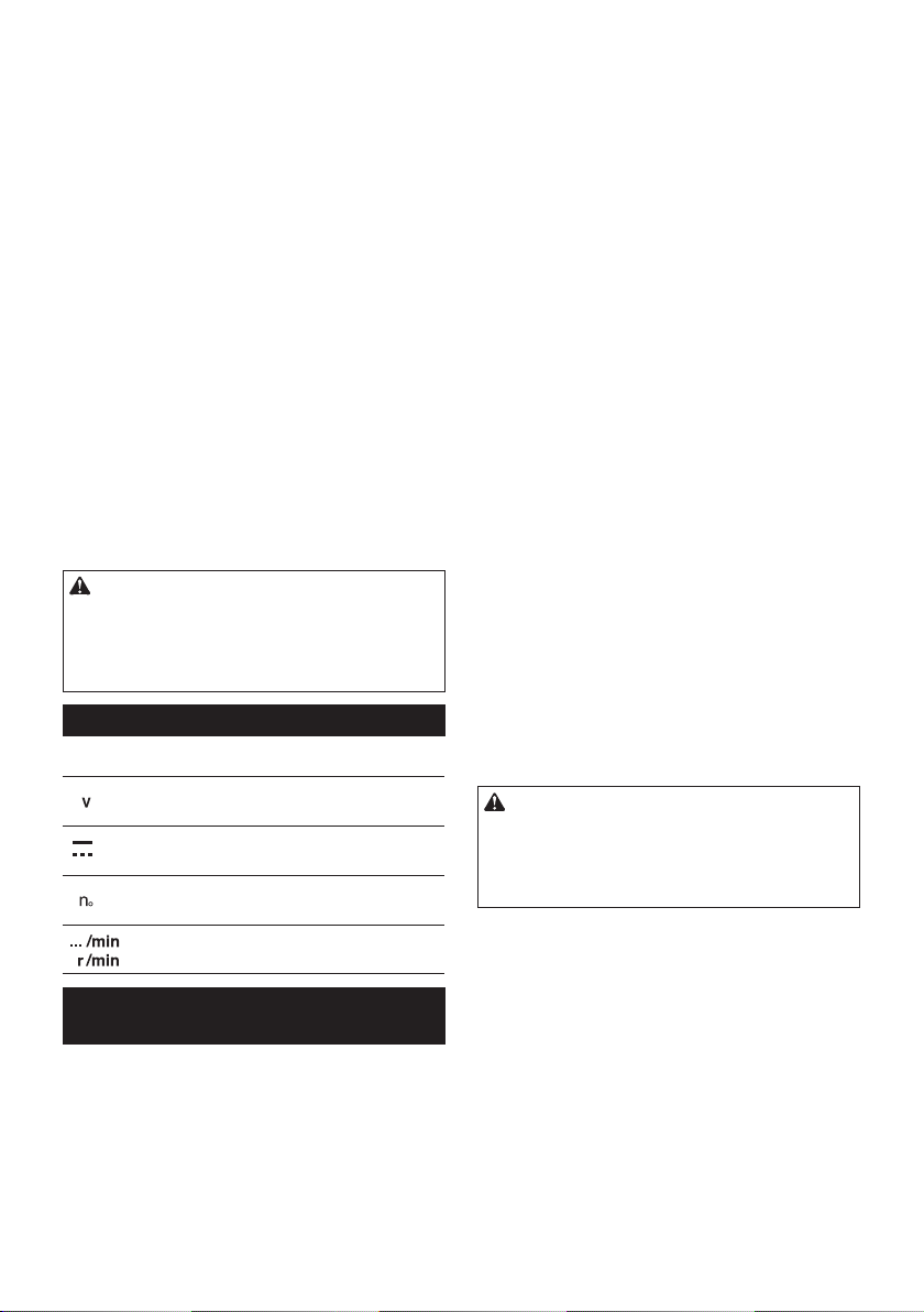
►1. Red indicator 2. Button 3. Battery cartridge
Toremovethebatterycartridge,slideitfromthetool
while sliding the button on the front of the cartridge.
Toinstallthebatterycartridge,alignthetongueonthe
battery cartridge with the groove in the housing and slip
it into place. Insert it all the way until it locks in place
with a little click. If you can see the red indicator on the
upper side of the button, it is not locked completely.
CAUTION: Always install the battery cartridge
fully until the red indicator cannot be seen. If not,
itmayaccidentallyfalloutofthetool,causinginjuryto
you or someone around you.
CAUTION: Do not install the battery cartridge
forcibly. If the cartridge does not slide in easily, it is
not being inserted correctly.
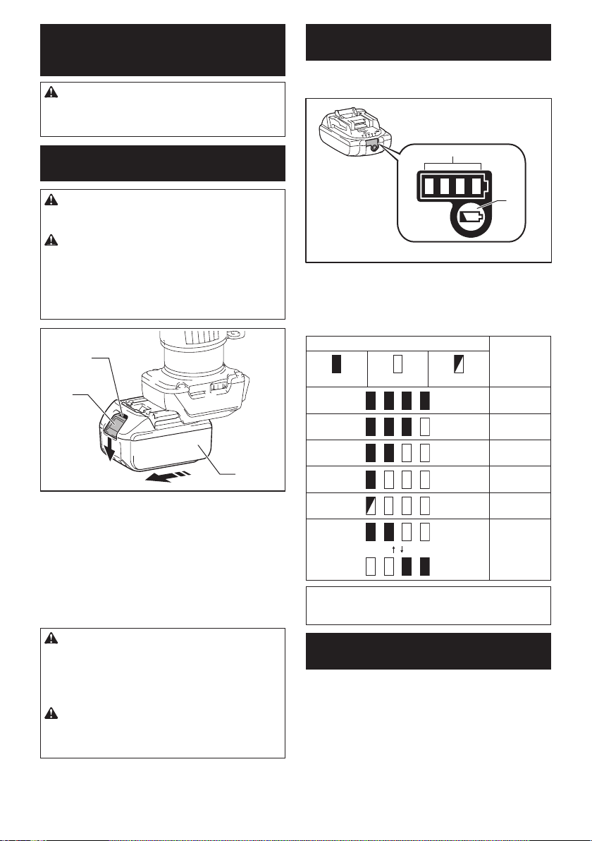
Indicating the remaining battery
capacity
Only for battery cartridges with the indicator
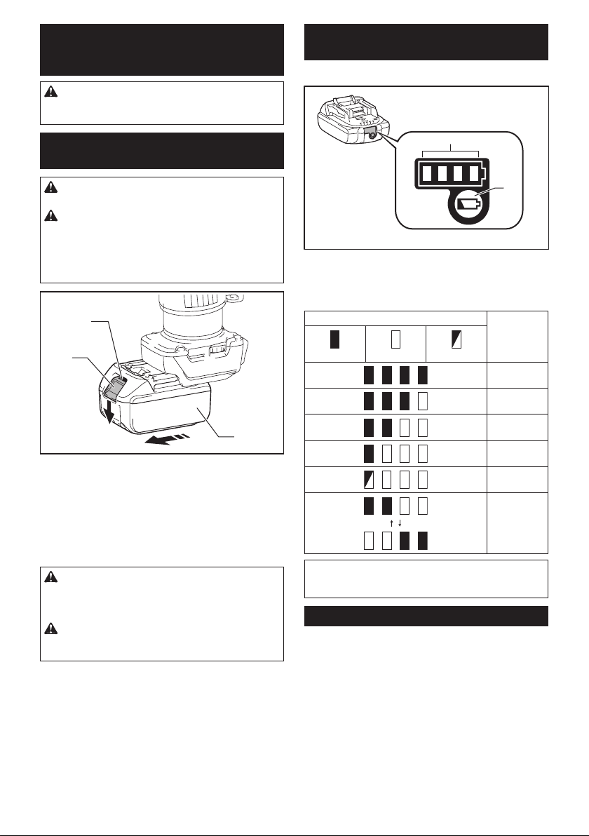
1
2
►1. Indicator lamps 2. Check button
Press the check button on the battery cartridge to indi-
catetheremainingbatterycapacity.Theindicatorlamps
light up for few seconds.
Indicator lamps Remaining
capacity
Lighted Off Blinking
75% to 100%
50% to 75%
25% to 50%
0% to 25%
Charge the
battery.
Thebattery
may have
malfunctioned.
NOTE: Depending on the conditions of use and the
ambient temperature, the indication may differ slightly
from the actual capacity.
Tool / battery protection system
Thetoolisequippedwithatool/batteryprotectionsys-
tem.Thissystemautomaticallycutsoffpowertothe
motortoextendtoolandbatterylife.Thetoolwillauto-
matically stop during operation if the tool or battery is
placed under one of the following conditions:
Overload protection
When the battery is operated in a manner that causes
it to draw an abnormally high current, the tool automat-
ically stops without any indication. In this situation, turn
the tool off and stop the application that caused the tool
tobecomeoverloaded.Thenturnthetoolontorestart.
6ENGLISH
Overheat protection
When the tool or battery is overheated, the tool stops
automatically and the lamp blinks. In this case, let the
tool and battery cool before turning the tool on again.
Overdischarge protection
When the battery capacity is not enough, the tool stops
automatically. In this case, remove the battery from the
tool and charge the battery.
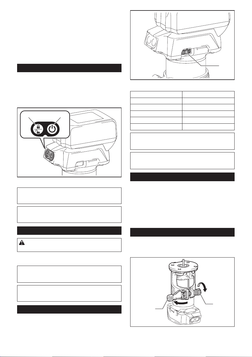
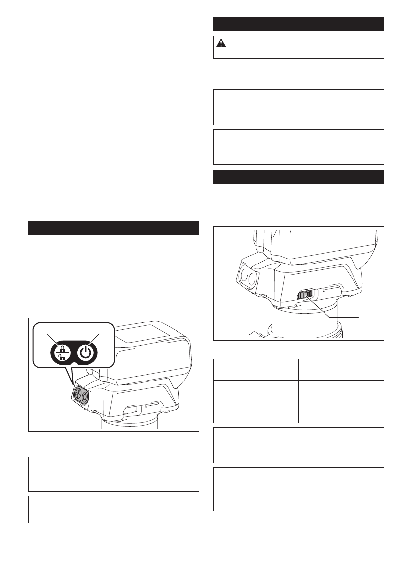
Switch action
Toturnonthetool,pressthelock/unlockbutton.The
toolturnsintothestandbymode.Tostartthetool,press
thestart/stopbuttoninthestandbymode.Tostopthe
tool,pressthestart/stopbuttonagain.Thetoolturns
intothestandbymode.Toturnoffthetool,pressthe
lock/unlock button in the standby mode.
21
►1. Lock/unlock button 2. Start/stop button
NOTE: If the tool is left for 10 seconds without any
operation in the standby mode, the tool automatically
turns off and the lamp goes off.
NOTE: You can also stop and turn off the tool by
pressing the lock/unlock button while the tool is
operating.
Lighting up the front lamp
CAUTION: Do not look in the light or see the
source of light directly.
Toturnonthelamp,pressthelock/unlockbutton.To
turn off the lamp, press the lock/unlock button again.
NOTICE: When the tool is overheated, the lamp
ickers. Cool down the tool fully before operating
the tool again.
NOTE: Use a dry cloth to wipe the dirt off the lens of
the lamp. Be careful not to scratch the lens of lamp, or
it may lower the illumination.
Speed adjusting dial
Therotationspeedofthetoolcanbechangedbyturn-
ingthespeedadjustingdial.Thetablebelowshows
the number on the dial and the corresponding rotation
speed.
1
►1.Speedadjustingdial
Number Speed
110,000/min
215,000/min
320,000/min
425,000/min
530,000/min
NOTICE: If the tool is operated continuously at
low speed for a long time, the motor will get over-
loaded, resulting in tool malfunction.
NOTICE: When changing the speed dial from "5"
to "1", turn the dial counterclockwise. Do not turn
the dial clockwise forcibly.
Electronic function
Thetoolisequippedwiththeelectronicfunctionsfor
easy operation.
• Constantspeedcontrol
Thespeedcontrolfunctionprovidestheconstant
rotation speed regardless of load conditions.
• Softstart
Thesoft-startfunctionminimizesstart-upshock,
and makes the tool start smoothly.
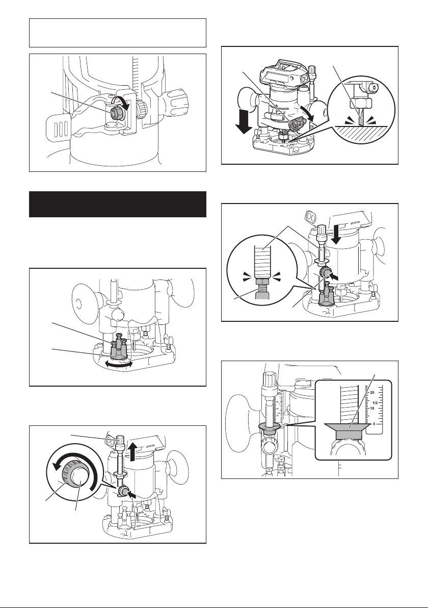
Adjusting cutting depth
Toadjustthecuttingdepth,openthelocklever,then
movethetoolbaseupordownbyturningtheadjusting
screw.Aftertheadjustment,closethelockleverrmly.
2
1
►1. Lock lever 2.Adjustingscrew
7ENGLISH
NOTICE: If the tool is not secured after closing
the lock lever, tighten the hex nut, and then close
the lock lever.
1
►1. Hex nut
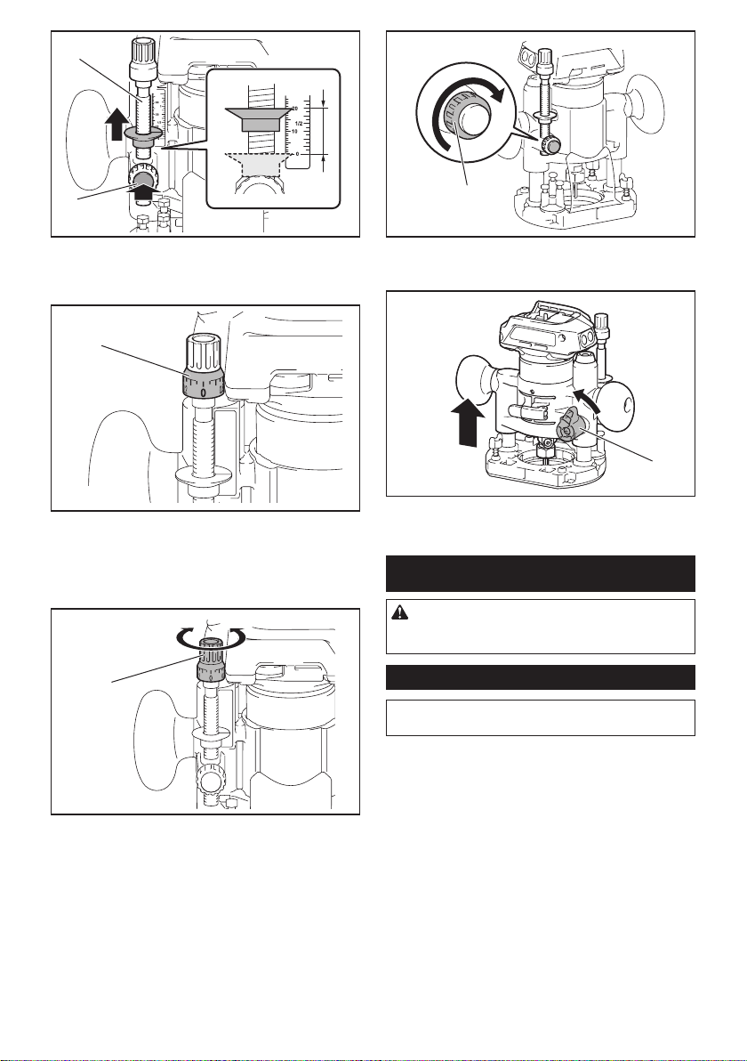
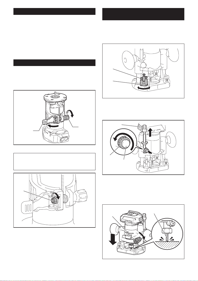
Adjusting cutting depth with the
plunge base
Optional accessory
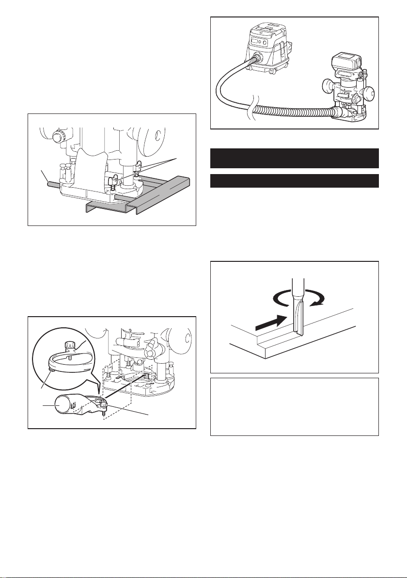
1. Placethetoolontheatsurface.
2. Select the stopper screw by rotating the stopper
base.
1
2
►1. Stopper screw 2. Stopper base
3. Loosenthestopperpolexingnut,thenpullupthe
stopper pole while pressing the feed button.
2
3
1
►1. Stopper pole 2. Fixing nut 3. Feed button
4. Push down the tool until the tip of the trimmer bit
touchestheatsurface,andthenturnthexingleverto
secure the tool.
12
►1. Fixing lever 2.Trimmerbit
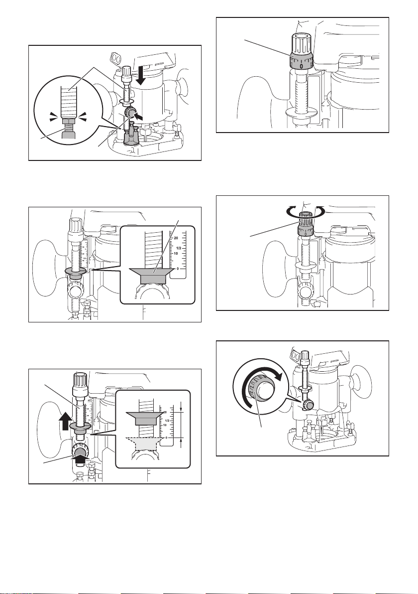
5. Press down the stopper pole while pressing the
feed button until it contacts the stopper screw.
2
3
1
►1. Stopper pole 2. Stopper screw 3. Feed button
6. Slide the depth pointer so that the pointer indi-
cates "0" on the scale.
1
►1. Depth pointer
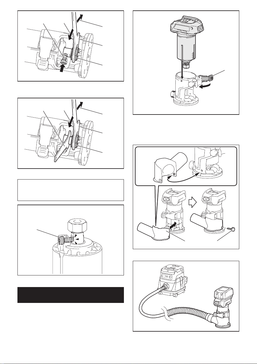
7. Adjustthecuttingdepthbypullingupthestopper
pole while pressing the feed button.
8ENGLISH
1
2
►1. Stopper pole 2. Feed button
8. Toperformneadjustmentofthecuttingdepth,
turn the dial on the stopper pole so that it indicates "0".
1
►1. Dial
9. Turntheheadofthestopperpoletoobtainthe
desireddepth.Toincreasethedepth,turnthehead
counterclockwise.Todecreasethedepth,turnthehead
clockwise.
1
►1. Head of the stopper pole
10. Tightenthestopperpolexingnut.
1
►1. Fixing nut
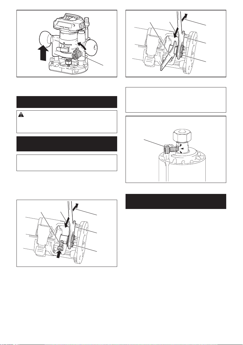
11. Releasethexinglever.
1
►1. Fixing lever
ASSEMBLY
CAUTION: Always be sure that the tool is
switched off and the battery cartridge is removed
before carrying out any work on the tool.
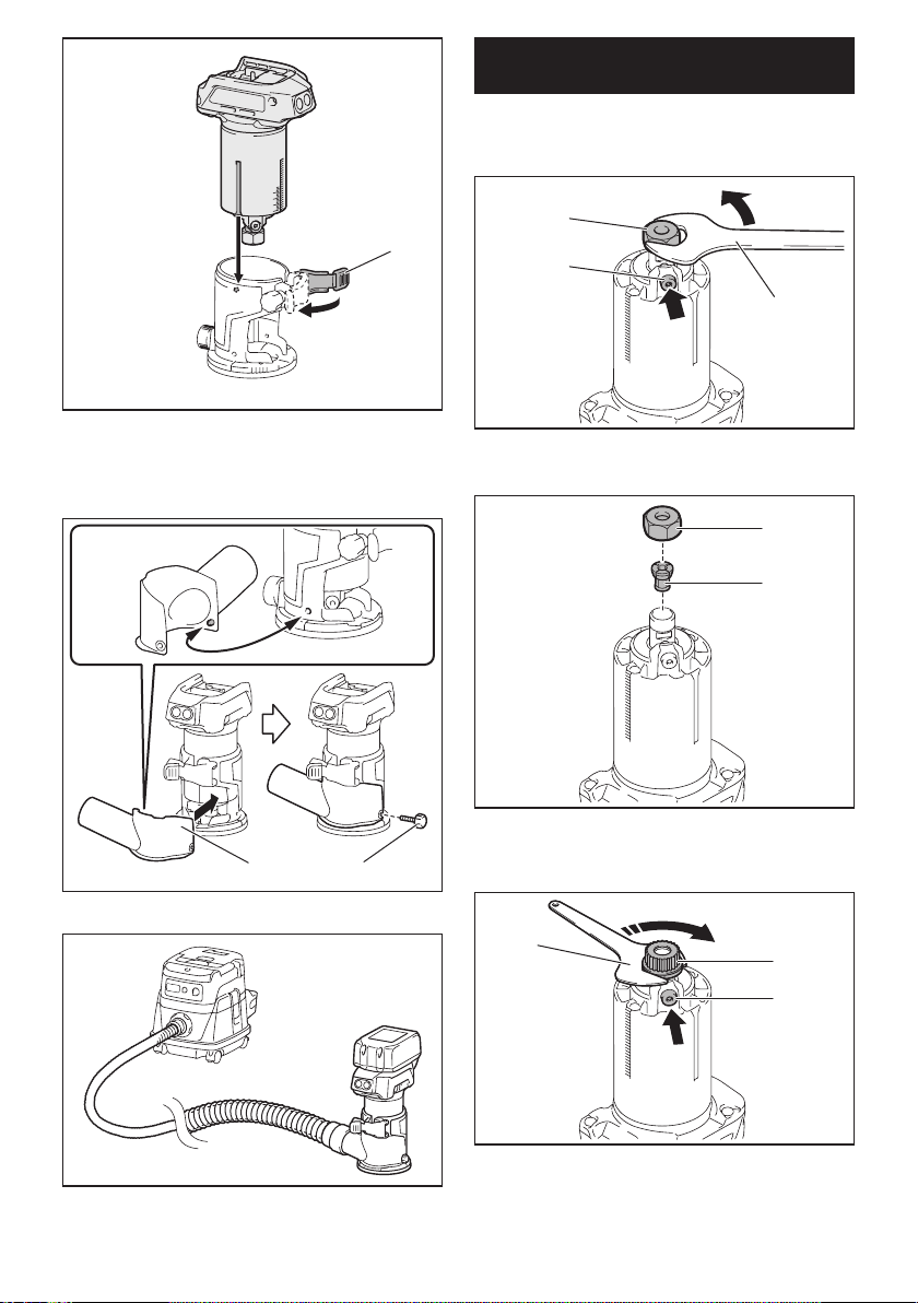
Installing or removing trimmer bit
NOTICE: Do not tighten the collet nut without
inserting the bit.Thecolletconemaybreak.
Insert the trimmer bit all the way into the collet cone.
Press the shaft lock and tighten the collet nut with the
wrench or tighten the collet nut securely with the two
wrenches.Toremovethebit,followtheinstallation
procedure in reverse.
9ENGLISH
12
3
4
5
►1. Shaft lock 2. Loosen 3.Tighten4. Wrench
5. Collet nut
12
3
1
4
►1. Wrench 2. Loosen 3.Tighten4. Collet nut
NOTE:Theshaftlockmaynotreturntotheoriginal
position when you tighten the collet nut at the instal-
lationofthetrimmerbit.Theshaftlockreturnstothe
original position when you start the tool.
1
►1. Shaft lock
Installing or removing the trimmer
base
1. Open the lock lever of the trimmer base, then
insert the tool into the trimmer base aligning the groove
on the tool with the protrusion on the trimmer base.
1
►1. Lock lever
2. Close the lock lever.
3. Attachthedustnozzletothetrimmerbase,and
then tighten the thumb screw.
12
►1. Dust nozzle 2.Thumbscrew
Toremovethebase,followtheinstallationprocedure
in reverse.
10 ENGLISH
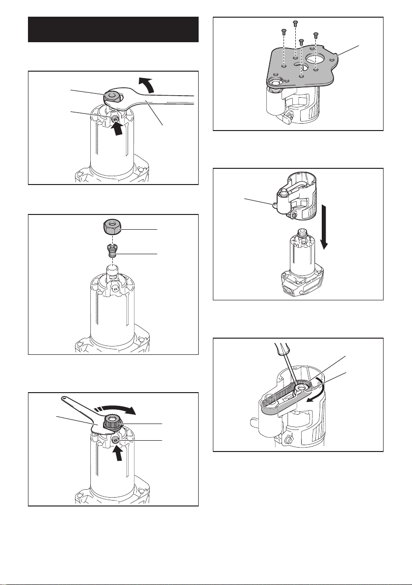
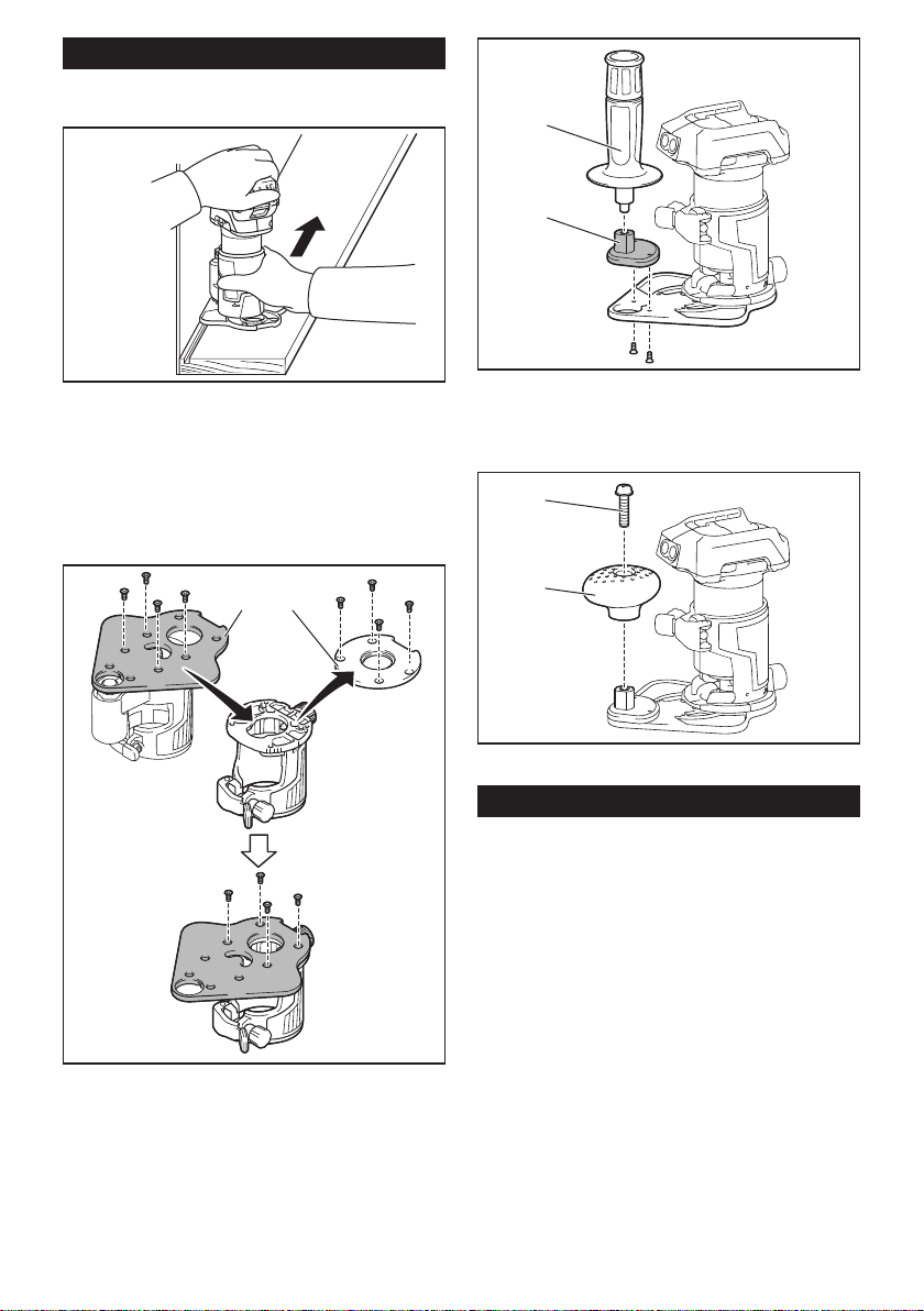
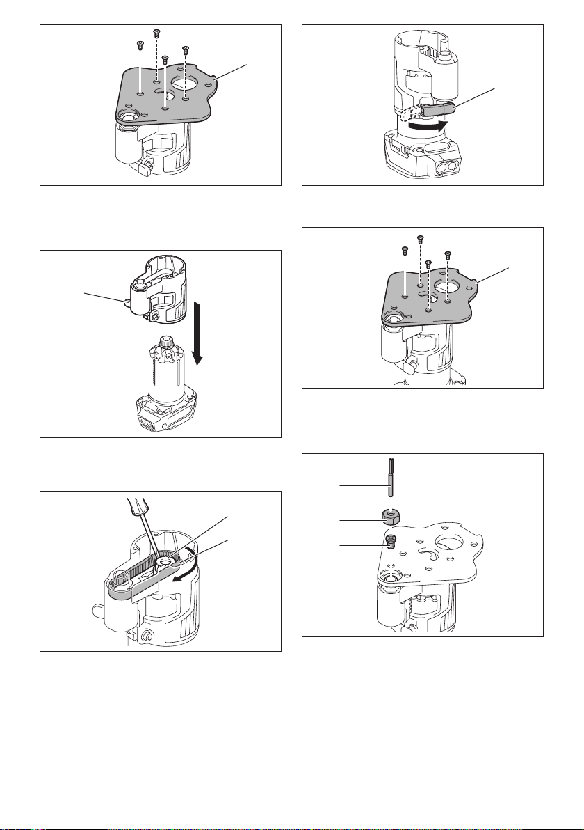
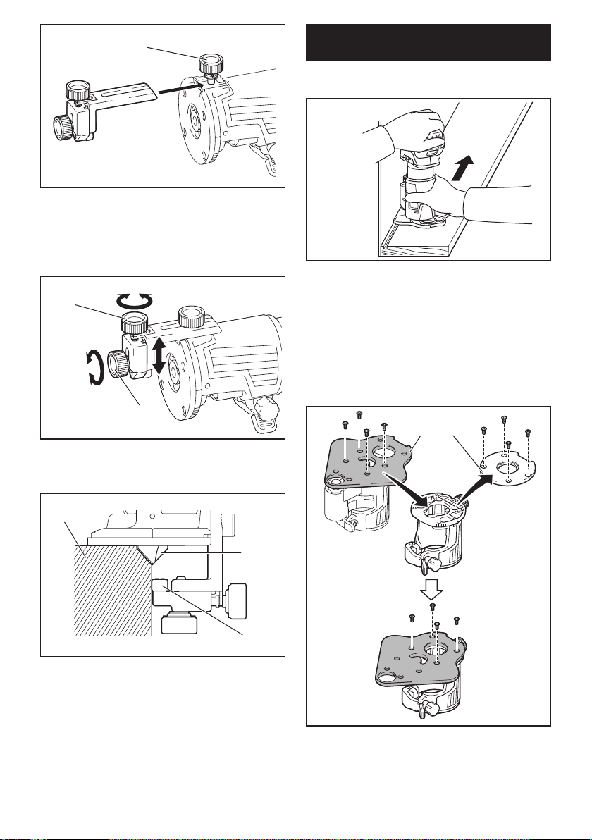
Installing or removing the offset
base
Optional accessory
1. Press the shaft lock, then loosen the collet nut.
1
2
3
►1. Collet nut 2. Shaft lock 3. Wrench
2. Remove the collet nut and the collet cone.
1
2
►1. Collet nut 2. Collet cone
3. Install the pulley on the tool by pressing the shaft
lock and tightening the pulley with the wrench.
1
2
3
►1. Wrench 2. Pulley 3. Shaft lock
4. Loosen the screws on the base plate, and then
remove the base plate.
1
►1. Base plate
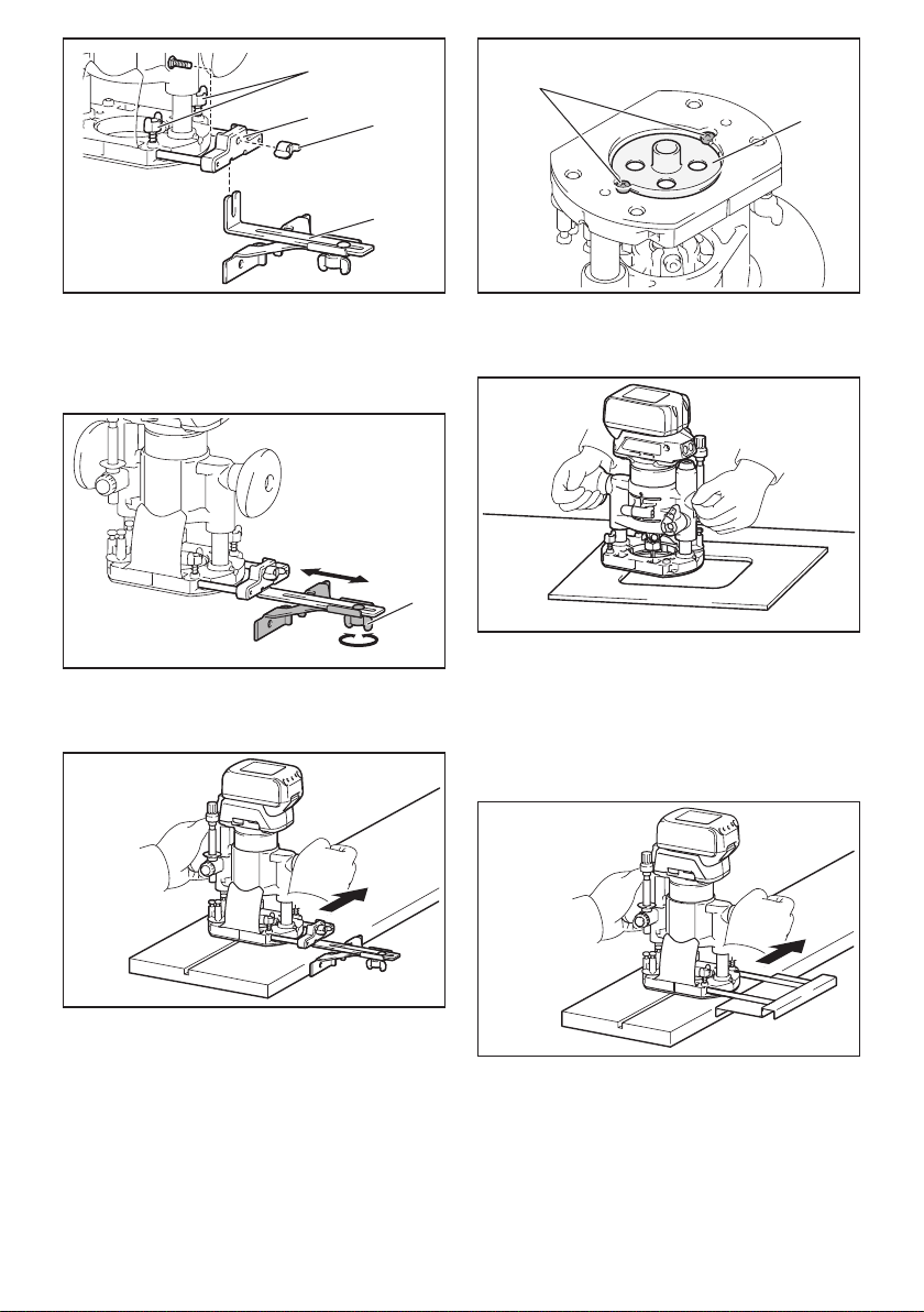
5. Open the lock lever of the offset base, then insert
the tool into the offset base.
1
►1. Lock lever
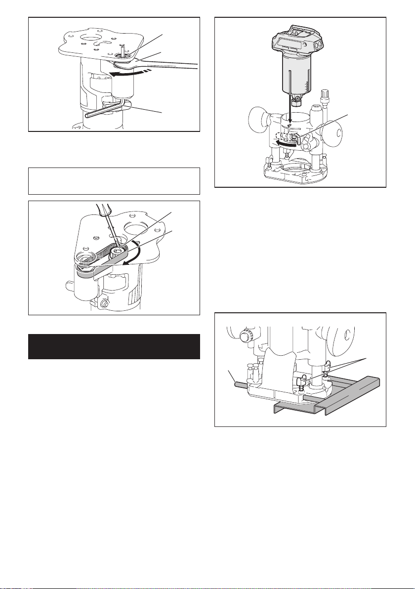
6. Mount the belt to the pulley by rotating the belt
manually.
2
1
►1. Pulley 2. Belt
7. Close the lock lever.
11 ENGLISH
1
►1. Lock lever
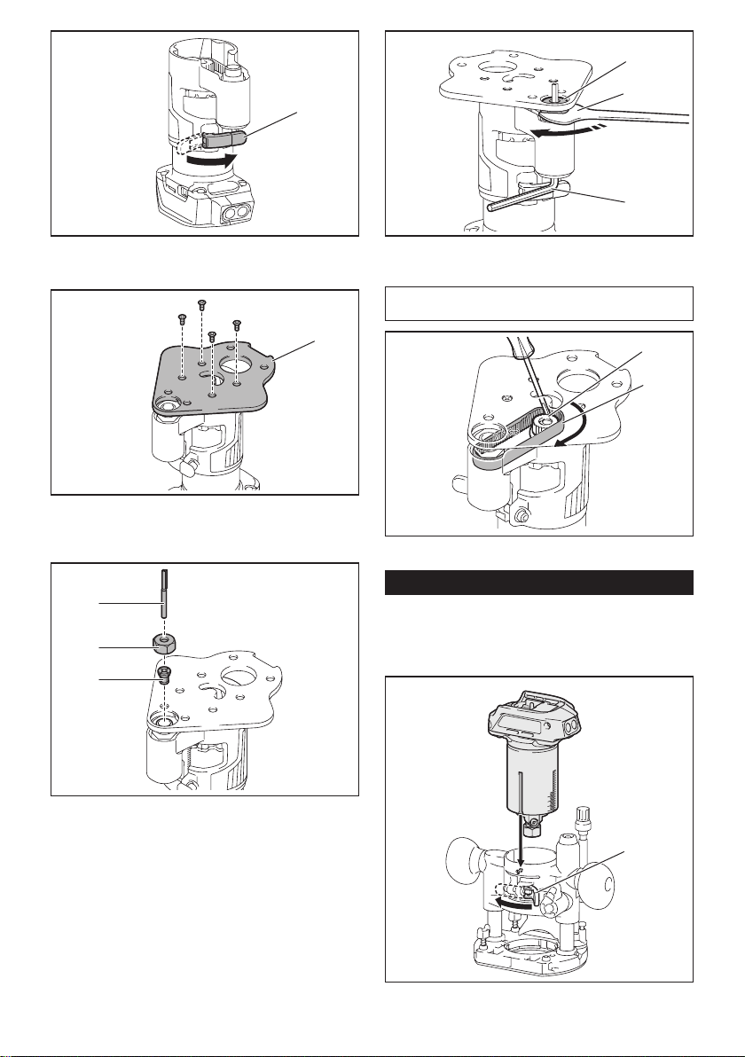
8. Attachthebaseplatebytighteningthescrews.
1
►1. Base plate
9. Insert the collet cone and the trimmer bit into the
offset base, and then tighten the collet nut.
1
2
3
►1.Trimmerbit2. Collet nut 3. Collet cone
10. Insert the hex wrench into the hole of the offset
base, and then tighten the collet nut with the wrench.
1
2
3
►1. Collet nut 2. Wrench 3. Hex wrench
Toremovethebase,followtheinstallationprocedureinreverse.
NOTE: You can also mount the belt to the pulley with-
outremovingthebaseplateasshowninthegure.
2
1
►1. Pulley 2. Belt
Installing or removing the plunge base
Optional accessory
1.
Open the lock lever of the plunge base, then insert
the tool into the plunge base all the way aligning the
groove on the tool with the protrusion on the plunge base.
1
►1. Lock lever
12 ENGLISH
2. Close the lock lever.
Toremovethebase,followtheinstallationprocedure
in reverse.
Installing or removing the parallel
ruler on the plunge base
Optional accessory
Insert the guide bars into the holes in the plunge base,
andthentightenthewingbolts.Toremovetheruler,
follow the installation procedure in reverse.
1
2
►1. Wing bolt 2. Guide bar
Installing or removing the dust
nozzle on the plunge base
Insert the dust nozzle into the plunge base so that the
protrusiononthedustnozzletsinthenotchinthe
plunge base, and then tighten the thumb screw on the
dustnozzle.Toremovethenozzle,followtheinstalla-
tion procedure in reverse.
1
2
3
►1. Protrusion 2. Dust nozzle 3.Thumbscrew
OPERATION
Using the tool with the trimmer base
Set the tool base on the workpiece without the trimmer
bitmakinganycontact.Turnthetoolonandwaituntil
the bit attains full speed. Move the tool forward over
theworkpiecesurface.Keepthetoolbaseushwhile
moving the tool.
When cutting the edge, be sure to keep the workpiece
surface on the left side of the trimmer bit in the feed
direction.
NOTE: Before cutting on the actual workpiece, it is
recommendedtomakeasamplecut.Theproperfeed
speed depends on the bit size, the kind of workpiece,
and depth of cut. Moving the tool forward too fast may
cause a poor quality of cut, or damage to the bit or
motor. Moving the tool forward too slowly may burn
and mar the cut.
When using the trimmer shoe, the straight guide, or the
trimmer guide, be sure to keep it on the right side in the
feeddirection.Thiswillhelptokeepitushwiththeside
of the workpiece.
13 ENGLISH
1
3
2
►1.Trimmerbit2. Workpiece 3. Straight guide
NOTICE: Since excessive cutting may cause
overload of the motor or difculty in controlling
the tool, the depth of cut should not be more than
3 mm (1/8") at a pass when cutting grooves. When
you wish to cut grooves more than 3 mm (1/8") deep,
make several passes with progressively deeper bit
settings.
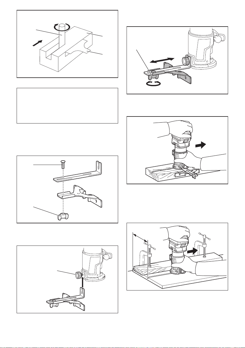
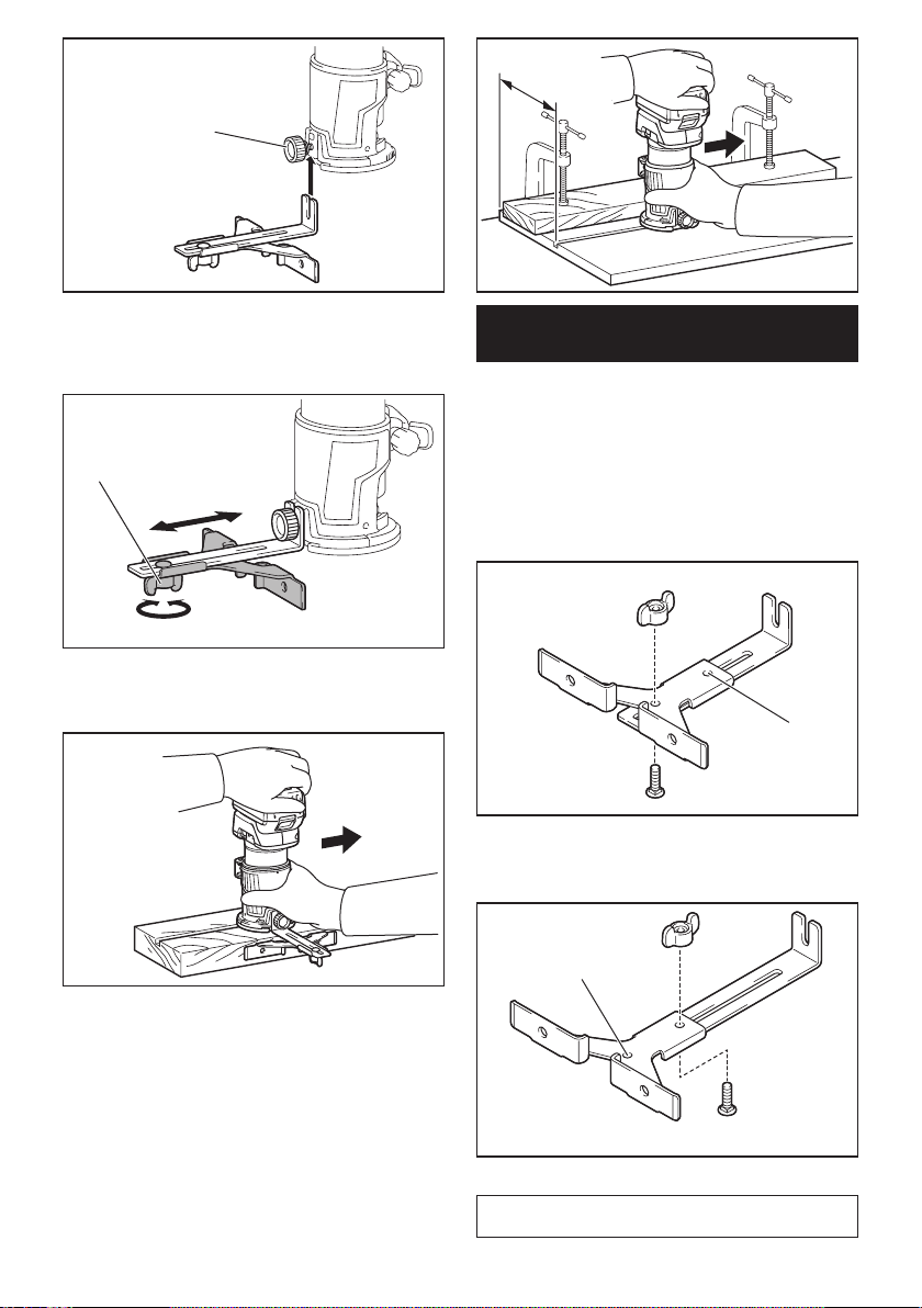
Using the straight guide
Optional accessory
1. Assemblethestraightguidewiththeboltandthe
wing nut.
2
1
►1. Bolt 2. Wing nut
2. Attachthestraightguidetothetrimmerbasewith
the clamp screw.
1
►1. Clamp screw
3. Loosen the wing nut on the straight guide and
adjustthedistancebetweenthebitandthestraight
guide.Atthedesireddistance,tightenthewingnut.
1
►1. Wing nut
4. Movethetoolwiththestraightguideushwiththe
side of the workpiece.
Ifthedistance(A)betweenthesideoftheworkpiece
and the cutting position is too wide for the straight
guide, or if the side of the workpiece is not straight, the
straight guide cannot be used.
Inthiscase,rmlyclampastraightboardtothework-
piece and use it as a guide against the trimmer base.
Feed the tool in the direction of the arrow.
A
14 ENGLISH
Using the straight guide for circular
work
For circular work, assemble the straight guide as shown
inthegures.Theminimumandmaximumradiusof
circles to be cut (distance between the center of circle
and the center of bit) are as follows:
• Minimum:70mm(2-3/4")
• Maximum:221mm(8-11/16")
For cutting circles between 70 mm (2-3/4") and 121
mm (4-3/4") in radius.
1
►1. Center hole
For cutting circles between 121 mm (4-3/4") and 221
mm (8-11/16") in radius.
1
►1. Center hole
NOTE: Circles between 172 mm (6-3/4") and 186 mm
(7-5/16") in radius cannot be cut using this guide.
Alignthecenterholeinthestraightguidewiththe
center of the circle to be cut. Drive a nail less than 6
mm (1/4") in diameter into the center hole to secure
the straight guide. Pivot the tool around the nail in the
clockwise direction.
2
1
►1. Nail 2. Center hole
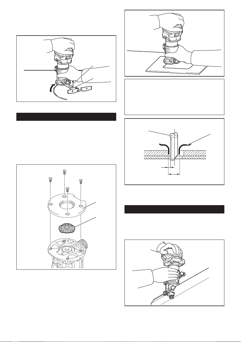
Using the templet guide
Optional accessory
Thetempletguideallowsforrepetitivecutwithtemplet
patterns by using a templet.
1. Loosen the screws on the base plate, and then
remove the base plate from the trimmer base.
2. Place the templet guide on the base, and then
attach the base plate by tightening the screws.
1
2
►1. Base plate 2.Templetguide
3. Place the tool on the templet and move the tool
with the templet guide sliding along the side of the
templet.
15 ENGLISH
NOTE:Theactualcutsizeontheworkpieceisslightly
differentfromthetemplet.Thedifferenceisthedis-
tance (X) between the trimmer bit and the outside of
thetempletguide.Thedistance(X)canbecalculated
by using the following equation:
Distance (X) = (outside diameter of templet guide -
trimmer bit diameter) / 2
12
3
4
►1.Trimmerbit2.Templetguide3. Distance (X)
4. Outside diameter of templet guide
Using the trimmer guide
Optional accessory
Thetrimmerguideallowsfortrimmingcurvedsidelike
veneers for furniture by moving the guide roller along
the side of the workpiece.
1. Loosen the clamp screw, then install the trimmer
guide on the trimmer base, and then tighten the clamp
screw.
1
►1. Clamp screw
2. Loosentheclampscrewandadjustthedistance
between the trimmer bit and the trimmer guide by turn-
ingtheadjustingscrew(1mm(3/64")perturn).Atthe
desired distance, tighten the clamp screw to secure the
trimmer guide.
1
2
►1.Adjustingscrew2. Clamp screw
3. Move the tool with the guide roller riding the side
of the workpiece.
1
2
3
►1. Workpiece 2. Bit 3. Guide roller
z
16 ENGLISH
Using the tool with the offset base
Theoffsetbaseisconvenientforworkinatightarea
such as a corner.
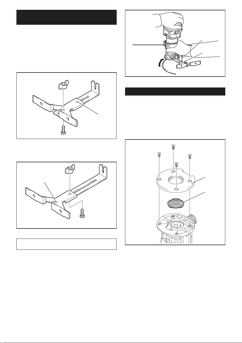
Using the trimmer base with the
offset base plate and grip
Theoffsetbaseplatecanalsobeusedwithatrimmer
base and a grip attachment (optional accessory) for
more stability.
1. Loosen the screws on the base plate, then remove
the base plate from the offset base.
12
►1. Offset base plate 2.Trimmerbaseplate
2. Attachtheoffsetbaseplatetothetrimmerbaseby
tightening the screws.
3. Attachthegripattachmentandthebartypegripto
the offset base plate by tightening the screws.
2
1
►1. Bar type grip 2. Grip attachment
Theknobtypegripremovedfromtheplungebasecan
be installed on the offset base instead of the bar type
grip.
1
2
►1. Screw 2. Knob type grip
Using the tool with the plunge base
Alwaysholdthegripsrmlywithbothhandsduring
operation. Operate the tool in the same way as the
trimmer base.
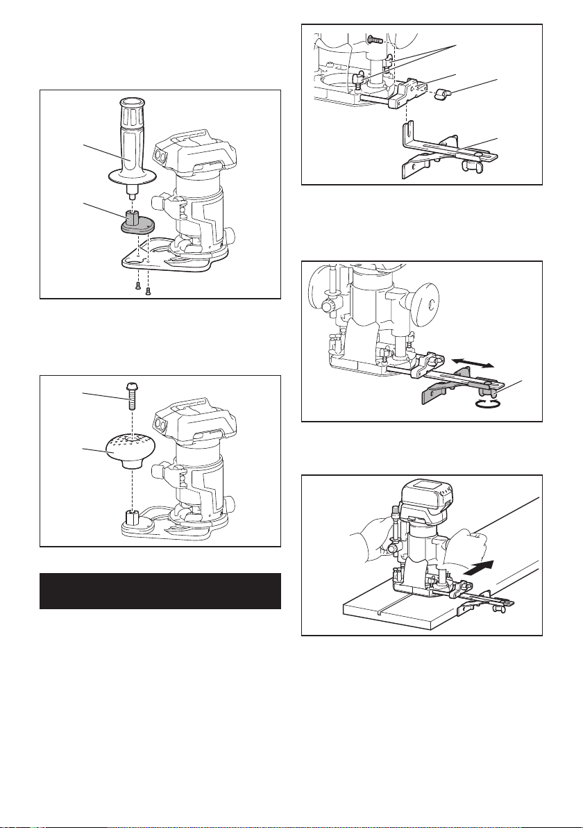
Using the straight guide
Optional accessory
1. Install the straight guide to the guide holder by
tightening the wing nut. Insert the guide holder into the
holes in the plunge base, and then tighten the wing
bolts.
17 ENGLISH
1
23
4
►1. Wing bolt 2. Guide holder 3. Wing nut 4. Straight
guide
2. Loosen the wing nut on the straight guide and
adjustthedistancebetweenthebitandthestraight
guide.Atthedesireddistance,tightenthewingnut.
1
►1. Wing nut
3. Operate the tool in the same way as the straight
guide for the trimmer base.
Using the templet guide
Optional accessory
1. Loosen the screws on the base and remove them.
Place the templet guide on the base, and then tighten
the screws.
1
2
►1. Screw 2.Templetguide
2. Operate the tool in the same way as the templet
guide for the trimmer base.
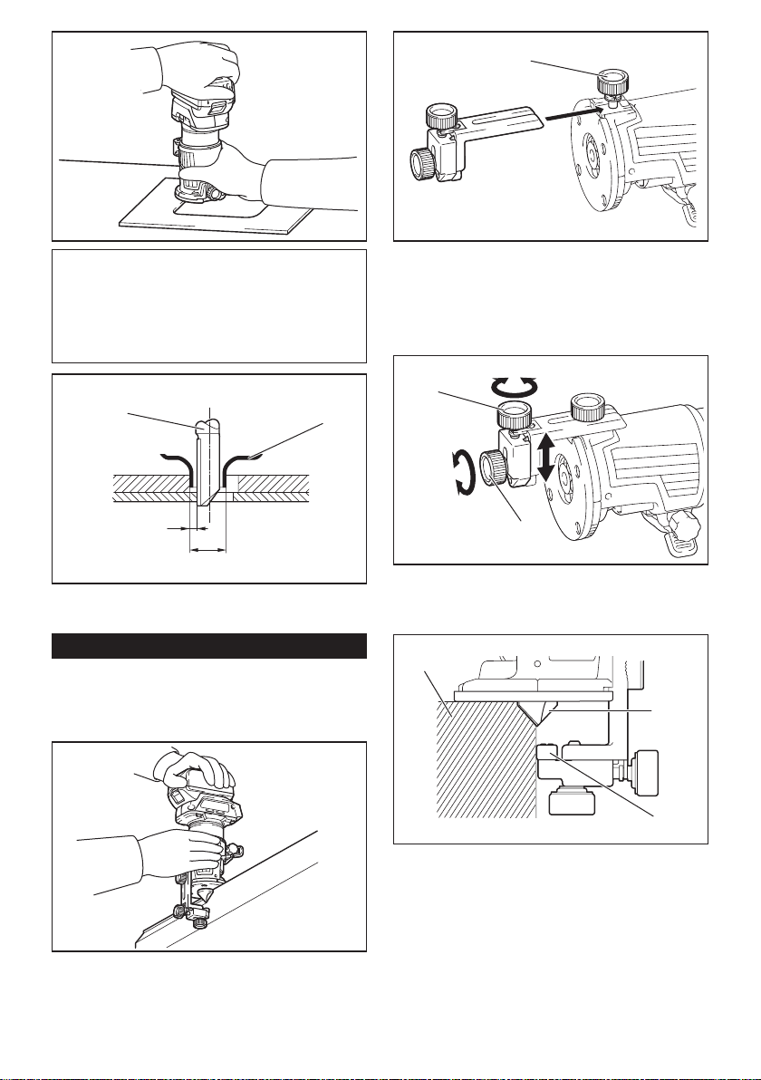
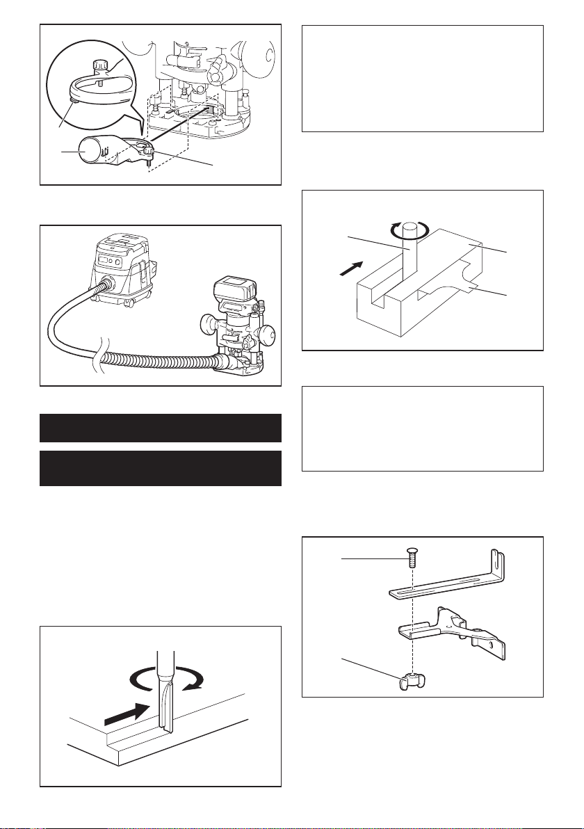
Using the parallel ruler
Theparallelruleriseffectivelyusedforstraightcuts
whenchamferingorgrooving.Adjustthedistance
betweenthebitandtheparallelruler.Atthedesired
distance, tighten the wing bolts to secure the parallel
ruler. When cutting, move the tool with the parallel ruler
ushwiththesideoftheworkpiece.
Ifthedistance(A)betweenthesideoftheworkpiece
and the cutting position is too wide for the parallel ruler,
or if the side of the workpiece is not straight, the parallel
ruler cannot be used.
Inthiscase,rmlyclampastraightboardtothework-
piece and use it as a guide against the plunge base.
Feed the tool in the direction of the arrow.
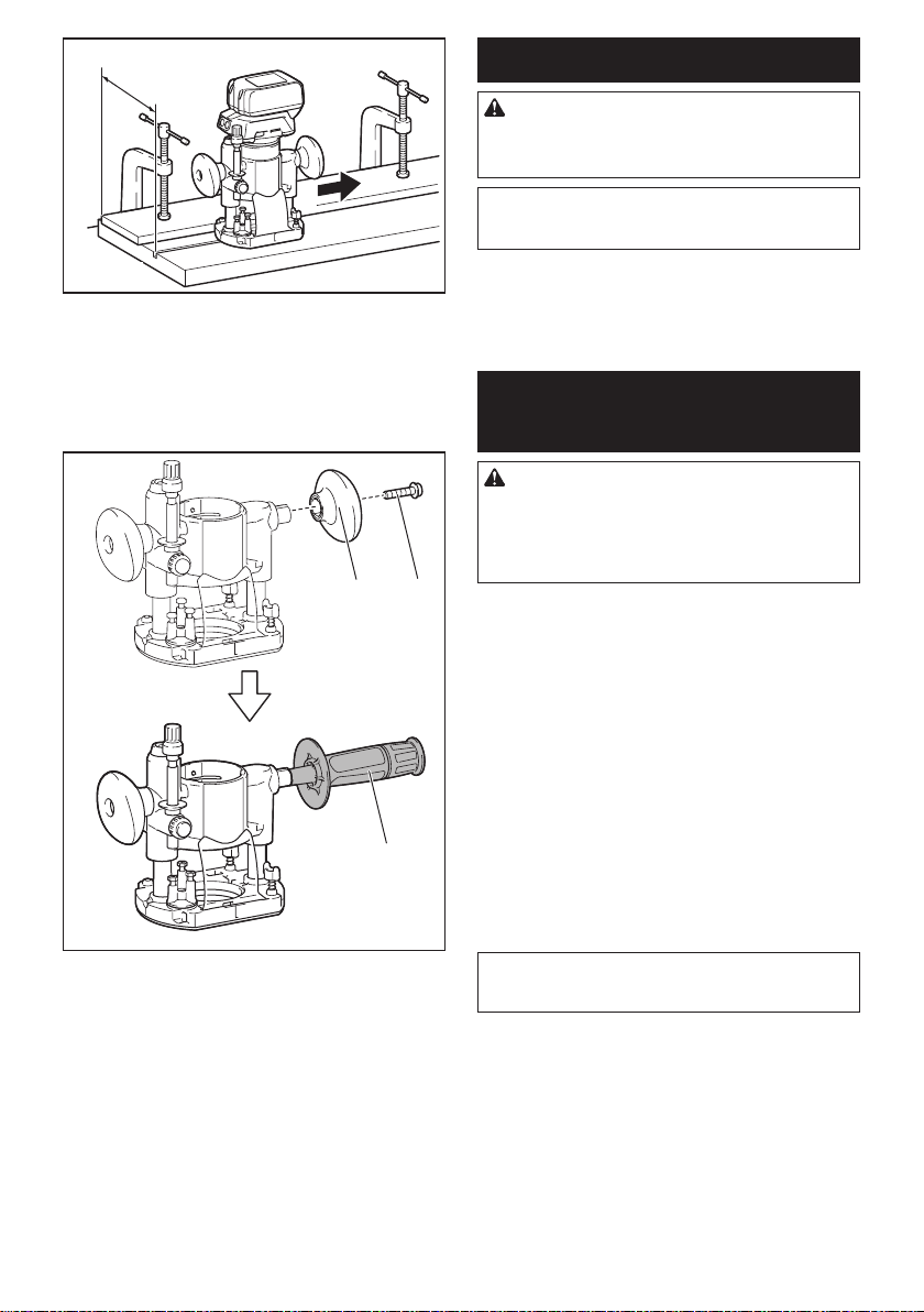
18 ENGLISH
A
Changing knob type grip to bar type
grip
Toinstallthebartypegripontheplungebase,loosen
the screw of the knob type grip, then remove the knob
type grip, and then install the bar type grip by tightening
it.
12
3
►1. Knob type grip 2. Screw 3. Bar type grip
MAINTENANCE
CAUTION: Always be sure that the tool is
switched off and the battery cartridge is removed
before attempting to perform inspection or
maintenance.
NOTICE: Never use gasoline, benzine, thinner,
alcohol or the like. Discoloration, deformation or
cracks may result.
TomaintainproductSAFETYandRELIABILITY,
repairs,anyothermaintenanceoradjustmentshould
beperformedbyMakitaAuthorizedorFactoryService
Centers, always using Makita replacement parts.
OPTIONAL
ACCESSORIES
CAUTION: These accessories or attachments
are recommended for use with your Makita tool
specied in this manual.Theuseofanyother
accessories or attachments might present a risk of
injurytopersons.Onlyuseaccessoryorattachment
for its stated purpose.
If you need any assistance for more details regarding
these accessories, ask your local Makita Service Center.
• Straightandgrooveformingbits
• Edgeformingbits
• Laminatetrimmingbits
• Straightguideassembly
• Trimmerguideassembly
• Trimmerbaseassembly
• Plungebaseassembly
• Offsetbaseassembly
• Gripattachment
• Templetguide
• Colletcone1/4"
• Colletcone3/8"
• Wrench13
• Wrench22
• Makitagenuinebatteryandcharger
NOTE: Some items in the list may be included in the
toolpackageasstandardaccessories.Theymay
differ from country to country.

19 ENGLISH
MAKITA LIMITED ONE YEAR
WARRANTY
Warranty Policy
Every Makita tool is thoroughly inspected and tested
before leaving the factory. It is warranted to be free of
defects from workmanship and materials for the period
ofONEYEARfromthedateoforiginalpurchase.
Should any trouble develop during this one year period,
returntheCOMPLETEtool,freightprepaid,toone
ofMakita’sFactoryorAuthorizedServiceCenters.If
inspection shows the trouble is caused by defective
workmanship or material, Makita will repair (or at our
option, replace) without charge.
ThisWarrantydoesnotapplywhere:
• repairshavebeenmadeorattemptedbyothers:
•
repairs are required because of normal wear and tear:
• thetoolhasbeenabused,misusedorimproperly
maintained:
• alterationshavebeenmadetothetool.
INNOEVENTSHALLMAKITABELIABLEFORANY
INDIRECT,INCIDENTALORCONSEQUENTIAL
DAMAGESFROMTHESALEORUSEOFTHE
PRODUCT.THISDISCLAIMERAPPLIESBOTH
DURINGANDAFTERTHETERMOFTHIS
WARRANTY.
MAKITADISCLAIMSLIABILITYFORANYIMPLIED
WARRANTIES,INCLUDINGIMPLIEDWARRANTIES
OF"MERCHANTABILITY"AND"FITNESSFORA
SPECIFICPURPOSE,"AFTERTHEONEYEARTERM
OFTHISWARRANTY.
ThisWarrantygivesyouspeciclegalrights,andyou
may also have other rights which vary from state to
state. Some states do not allow the exclusion or lim-
itation of incidental or consequential damages, so the
above limitation or exclusion may not apply to you.
Some states do not allow limitation on how long an
implied warranty lasts, so the above limitation may not
apply to you.

20 ESPAÑOL
ESPAÑOL (Instrucciones originales)
ESPECIFICACIONES
Modelo: XTR01
Capacidaddelapinzadesujeción 1/4″o3/8″
Velocidad sin carga 10 000 r/min - 30 000 r/min
Longitud total 226mm(8-7/8″)
Tensiónnominal 18 V c.c.
Batería estándar BL1815N / BL1820B / BL1830 / BL1830B / BL1840B /
BL1850B / BL1860B
Peso neto 1,8 kg - 2,1 kg (3,9 lbs - 4,6 lbs)
• Debidoanuestrocontinuoprogramadeinvestigaciónydesarrollo,lasespecicacionesaquíincluidasestán
sujetasacambiosinprevioaviso.
• Lasespecicacionesyelcartuchodebateríapuedenvariardepaísapaís.
• Elpesopuedevariarenfuncióndelosaccesorios,incluidoelcartuchodebatería.Enlatablasemuestrala
combinacióndepesomásligeroymáspesadoconformealprocedimiento01/2014deEPTA.
ADVERTENCIAS DE
SEGURIDAD
Advertencias generales de
seguridad para herramientas
eléctricas
ADVERTENCIA: Lea todas las advertencias
de seguridad, instrucciones, ilustraciones y espe-
cicaciones suministradas con esta herramienta
eléctrica. El no seguir todas las instrucciones indi-
cadasacontinuaciónpodríaocasionarunadescarga
eléctrica, incendio y/o lesiones graves.
Conserve todas las advertencias
e instrucciones como referencia
en el futuro.
En las advertencias, el término “herramienta eléctrica”
sereereasuherramientaeléctricadefuncionamiento
conconexiónalaredeléctrica(concableadoeléctrico)
o herramienta eléctrica de funcionamiento a batería
(inalámbrica).
Seguridad en el área de trabajo
1. Mantenga el área de trabajo limpia y bien ilu-
minada. Las áreas oscuras o desordenadas son
propensas a accidentes.
2. No utilice las herramientas eléctricas en
atmósferas explosivas, tal como en la presen-
cia de líquidos, gases o polvo inamables. Las
herramientas eléctricas crean chispas que pueden
prender fuego al polvo o los humos.
3. Mantenga a los niños y curiosos alejados
mientras utiliza una herramienta eléctrica. Las
distracciones le pueden hacer perder el control.
Seguridad eléctrica
1.
Las clavijas de conexión de las herramientas
eléctricas deberán encajar perfectamente en la
toma de corriente. No modique nunca la clavija
de conexión de ninguna forma. No utilice ninguna
clavija adaptadora con herramientas eléctricas
que tengan conexión a tierra (puesta a tierra). La
utilizacióndeclavijasnomodicadasyqueencajen
perfectamente en la toma de corriente reducirá el
riesgo de que se produzca una descarga eléctrica.
2.
Evite tocar con el cuerpo supercies conecta-
das a tierra o puestas a tierra tales como tubos,
radiadores, cocinas y refrigeradores. Si su cuerpo
es puesto a tierra o conectado a tierra existirá un
mayor riesgo de que sufra una descarga eléctrica.
3. No exponga las herramientas eléctricas a la
lluvia ni a condiciones húmedas. La entrada de
agua en una herramienta eléctrica aumentará el
riesgo de que se produzca una descarga eléctrica.
4. No maltrate el cable. Nunca utilice el cable
para transportar, jalar o desconectar la herra-
mienta eléctrica. Mantenga el cable alejado del
calor, aceite, objetos cortantes o piezas móvi-
les. Los cables dañados o enredados aumentan
el riesgo de sufrir una descarga eléctrica.
5.
Cuando utilice una herramienta eléctrica en
exteriores, utilice un cable de extensión apro-
piado para uso en exteriores.Lautilizacióndeun
cable apropiado para uso en exteriores reducirá el
riesgo de que se produzca una descarga eléctrica.
6. Si no es posible evitar usar una herramienta
eléctrica en condiciones húmedas, utilice un
alimentador protegido con interruptor de cir-
cuito de falla a tierra (ICFT).ElusodeunICFT
reduce el riesgo de descarga eléctrica.
7.
Las herramientas eléctricas pueden producir cam-
pos electromagnéticos (CEM) que no son dañinos
para el usuario. Sin embargo, si los usuarios tienen
marcapasos y otros dispositivos médicos similares,
deberán consultar al fabricante de su dispositivo y/o a
su médico antes de operar esta herramienta eléctrica.

21 ESPAÑOL
Seguridad personal
1. Manténgase alerta, preste atención a lo que
está haciendo y utilice su sentido común
cuando opere una herramienta eléctrica. No
utilice una herramienta eléctrica cuando esté
cansado o bajo la inuencia de drogas, alco-
hol o medicamentos.Unmomentodedistracción
mientras opera las herramientas eléctricas puede
terminarenunalesióngrave.
2. Use equipo de protección personal. Póngase
siempre protección para los ojos. El equipo
protector tal como máscara contra el polvo, zapa-
tos de seguridad antiderrapantes, casco rígido y
protecciónparaoídosutilizadoenlascondiciones
apropiadas reducirá el riesgo de lesiones.
3. Impida el encendido accidental. Asegúrese
de que el interruptor esté en la posición de
apagado antes de conectar a la alimentación
eléctrica y/o de colocar el cartucho de batería,
así como al levantar o cargar la herramienta.
Cargar las herramientas eléctricas con su dedo
en el interruptor o enchufarlas con el interrup-
tor encendido hace que los accidentes sean
comunes.
4. Retire cualquier llave de ajuste o llave de
apriete antes de encender la herramienta. Una
llavedeajusteollavedeaprietequehayasido
dejadapuestaenunapartegiratoriadelaherra-
mientaeléctricapuedeocasionaralgunalesión.
5. No utilice la herramienta donde no alcance.
Mantenga los pies sobre suelo rme y el equi-
librio en todo momento.Estopermiteunmejor
control de la herramienta eléctrica en situaciones
inesperadas.
6. Use una vestimenta apropiada. No use ropa
suelta ni alhajas. Mantenga su cabello y ropa
alejados de las piezas móviles. Las prendas
devestirholgadas,lasalhajasyelcabellolargo
podríanengancharseenlaspiezasmóviles.
7. Si dispone de dispositivos para la conexión
de equipos de extracción y recolección de
polvo, asegúrese de conectarlos y utilizarlos
debidamente.Hacerusodelarecolecciónde
polvo puede reducir los riesgos relacionados con
el polvo.
8. No permita que la familiaridad adquirida
debido al uso frecuente de las herramientas
haga que se sienta conado e ignore los prin-
cipios de seguridad de las herramientas. Un
descuidopodríaocasionarunalesióngraveen
unafraccióndesegundo.
Mantenimiento y uso de la herramienta eléctrica
1. No fuerce la herramienta eléctrica. Utilice la
herramienta eléctrica correcta para su aplica-
ción. La herramienta eléctrica adecuada hará un
mejortrabajoydeformamásseguraalaveloci-
dad para la que ha sido fabricada.
2. No utilice la herramienta eléctrica si el inte-
rruptor no la enciende y apaga. Cualquier
herramienta eléctrica que no pueda ser contro-
lada con el interruptor es peligrosa y debe ser
reemplazada.
3. Desconecte la clavija de la fuente de alimen-
tación y/o retire la batería de la herramienta
eléctrica, en caso de ser removible, antes de
realizar ajustes, cambiar accesorios o almace-
nar las herramientas eléctricas.Talesmedidas
de seguridad preventivas reducirán el riesgo
de poner en marcha la herramienta eléctrica de
forma accidental.
4. Guarde la herramienta eléctrica que no use
fuera del alcance de los niños y no permita
que las personas que no están familiarizadas
con ella o con las instrucciones la operen. Las
herramientas eléctricas son peligrosas en manos
de personas que no saben operarlas.
5. Dé mantenimiento a las herramientas eléctri-
cas y los accesorios. Compruebe que no haya
piezas móviles desalineadas o estancadas,
piezas rotas y cualquier otra condición que
pueda afectar al funcionamiento de la herra-
mienta eléctrica. Si la herramienta eléctrica
está dañada, haga que la reparen antes de
utilizarla. Muchos de los accidentes son ocasio-
nados por no dar un mantenimiento adecuado a
las herramientas eléctricas.
6. Mantenga las herramientas de corte limpias
y losas. Si recibe un mantenimiento adecuado
ytienelosbordesalados,esprobablequela
herramienta se atasque menos y sea más fácil
controlarla.
7. Utilice la herramienta eléctrica, los accesorios
y las brocas de acuerdo con estas instruccio-
nes, considerando las condiciones laborales
y el trabajo a realizar. Si utiliza la herramienta
eléctrica para realizar operaciones distintas de
lasindicadas,podrápresentarseunasituación
peligrosa.
8. Mantenga los mangos y supercies de asi-
miento secos, limpios y libres de aceite o
grasa.Losmangosysuperciesdeasimiento
resbalososnopermitenunamanipulaciónsegura
ni el control de la herramienta en situaciones
inesperadas.
9. Cuando vaya a utilizar esta herramienta, evite
usar guantes de trabajo de tela ya que éstos
podrían atorarse.Silosguantesdetrabajode
telallegaranaatorarseenlaspiezasmóviles,
esto podría ocasionar lesiones personales.
Uso y cuidado de la herramienta a batería
1. Recargue sólo con el cargador especicado
por el fabricante. Un cargador que es adecuado
para un solo tipo de batería puede generar riesgo
de incendio al ser utilizado con otra batería.
2. Utilice las herramientas eléctricas solamente
con las baterías designadas especícamente
para ellas.Lautilizacióndecualquierotrabatería
puede crear un riesgo de lesiones o incendio.
3. Cuando no se esté usando la batería, mantén-
gala alejada de otros objetos metálicos, como
sujetapapeles (clips), monedas, llaves, clavos,
tornillos u otros objetos pequeños de metal
los cuales pueden actuar creando una cone-
xión entre las terminales de la batería. Originar
un cortocircuito en las terminales puede causar
quemaduras o incendios.

22 ESPAÑOL
4. En condiciones abusivas, podrá escapar
líquido de la batería; evite tocarlo. Si lo toca
accidentalmente, enjuague con agua. Si hay
contacto del líquido con los ojos, busque asis-
tencia médica. Puede que el líquido expulsado
delabateríacauseirritaciónoquemaduras.
5. No utilice una herramienta ni una batería que
estén dañadas o hayan sido modicadas. Las
bateríasdañadasomodicadaspodríanoca-
sionarunasituacióninesperadaprovocandoun
incendio,explosiónoriesgodelesiones.
6. No exponga la herramienta ni la batería al
fuego ni a una temperatura excesiva. La expo-
siciónalfuegooaunatemperaturasuperioralos
130°Cpodríacausarunaexplosión.
7.
Siga todas las instrucciones para la carga y
evite cargar la herramienta o la batería fuera del
rango de temperatura especicado en las ins-
trucciones. Una carga inadecuada o a una tempe-
raturafueradelrangoespecicadopodríadañarla
batería e incrementar el riesgo de incendio.
Servicio
1. Haga que una persona calicada repare la
herramienta eléctrica utilizando sólo piezas de
repuesto idénticas. Esto asegura que se man-
tenga la seguridad de la herramienta eléctrica.
2. Nunca dé servicio a baterías que estén daña-
das. El servicio a las baterías solamente deberá
ser efectuado por el fabricante o un agente de
servicio autorizado.
3. Siga las instrucciones para la lubricación y
cambio de accesorios.
4. Mantenga las agarraderas secas, limpias y sin
aceite o grasa.
Advertencias de seguridad para la
recortadora inalámbrica
1. Sujete la herramienta eléctrica solamente
por las supercies de asimiento aisladas, ya
que la pieza de corte podría hacer contacto
con cableado oculto. Si se corta un cable con
corriente, las piezas metálicas expuestas de la
herramienta eléctrica se cargarán también de
corriente y el operador podría recibir una des-
carga eléctrica.
2.
Utilice abrazaderas o algún otro medio práctico
para asegurar y sujetar la pieza de trabajo a una
plataforma estable.Sostenerlapiezadetrabajo
con la mano o contra su cuerpo produce inestabili-
dad y puede ocasionar la pérdida de control.
3. Póngase protección para los oídos durante los
periodos de operación prolongados.
4. Manipule las fresas de la recortadora con
mucho cuidado.
5. Inspeccione la fresa de la recortadora cuida-
dosamente para ver si tiene grietas o daños
antes de la operación. Reemplace la fresa
inmediatamente si está agrietada o dañada.
6.
Evite cortar clavos. Inspeccione y quite todos los
clavos de la pieza de trabajo antes de la operación.
7. Sostenga la herramienta con rmeza.
8. Mantenga las manos alejadas de las piezas
giratorias.
9. Asegúrese de que la fresa de la recortadora no
esté haciendo contacto con la pieza de trabajo
antes de activar el interruptor.
10. Antes de usar la herramienta en una pieza
de trabajo, déjela un rato en funcionamiento.
Observe si se producen vibraciones o des-
equilibrios que pudieran indicar que la broca
está mal colocada.
11. Tenga cuidado con la dirección de giro y de
avance de la fresa de la recortadora.
12. No deje la herramienta en marcha. Tenga en
marcha la herramienta solamente cuando la
tenga en la mano.
13. Apague siempre la herramienta y espere hasta
que la fresa de la recortadora se haya detenido
por completo antes de retirar la herramienta de
la pieza de trabajo.
14. No toque la fresa de la recortadora inmediata-
mente después de la operación; podría estar
extremadamente caliente y provocarle quema-
duras en la piel.
15. No manche la base de la herramienta con dilu-
yente, gasolina, aceite o por el estilo. Estos
productos pueden ocasionar grietas en la base
de la herramienta.
16. Utilice fresas de la rebajadora de diámetro de
vástago correcto y apropiado para la velocidad
de la herramienta.
17. Algunos materiales contienen sustancias
químicas que pueden ser tóxicas. Tome pre-
cauciones para evitar la inhalación de polvo o
que éste tenga contacto con la piel. Consulte
la información de seguridad del proveedor de
los materiales.
18. Siempre utilice el respirador/máscara indicado
para protegerse del polvo que corresponda
con la aplicación o material con el que trabaje.
GUARDE ESTAS
INSTRUCCIONES.
ADVERTENCIA: NO DEJE que la comodidad
o familiaridad con el producto (a base de utilizarlo
repetidamente) sustituya la estricta observancia
de las normas de seguridad para dicho producto.
El MAL USO o el no seguir las normas de seguri-
dad establecidas en este manual de instrucciones
puede ocasionar lesiones personales graves.
Símbolos
Acontinuaciónsemuestranlossímbolosutilizados
para la herramienta.
volts o voltios
corriente directa o continua
velocidad sin carga
revoluciones o alternaciones por minuto,
frecuenciaderotación

23 ESPAÑOL
Instrucciones importantes de
seguridad para el cartucho de
batería
1. Antes de utilizar el cartucho de batería, lea
todas las instrucciones e indicaciones de
precaución en el (1) el cargador de batería, (2)
la batería, y (3) el producto con el que se utiliza
la batería.
2. No desarme el cartucho de batería.
3. Si el tiempo de operación se ha acortado en
exceso, deje de operar de inmediato. Podría
correrse el riesgo de sobrecalentamiento,
posibles quemaduras e incluso explosión.
4. En caso de que ingresen electrolitos en sus
ojos, enjuáguelos bien con agua limpia y con-
sulte de inmediato a un médico. Esto podría
ocasionar pérdida de visión.
5. Evite cortocircuitar el cartucho de batería:
(1) No toque las terminales con ningún mate-
rial conductor.
(2) Evite guardar el cartucho de batería en un
cajón junto con otros objetos metálicos,
tales como clavos, monedas, etc.
(3) No exponga el cartucho de batería al
agua o la lluvia.
Un cortocircuito en la batería puede causar
un ujo grande de corriente, sobrecalenta-
miento, posibles quemaduras e incluso una
descompostura.
6. No guarde la herramienta ni el cartucho de
batería en lugares donde la temperatura pueda
alcanzar o exceder los 50°C (122°F).
7. Nunca incinere el cartucho de batería incluso
en el caso de que esté dañado seriamente o
ya no sirva en absoluto. El cartucho de batería
puede explotar si se tira al fuego.
8. Tenga cuidado de no dejar caer ni golpear la
batería.
9. No use una batería dañada.
10. Las baterías de ión de litio están sujetas a los
requisitos reglamentarios en materia de bie-
nes peligrosos.
Paraeltrasportecomercial,porej.,mediante
terceros o agentes de transporte, se deben tomar
en cuenta los requisitos especiales relativos al
empaque y el etiquetado.
Para efectuar los preparativos del artículo que se
va a enviar, se requiere consultar a un experto
en materiales peligrosos. Si es posible, consulte
además otras regulaciones nacionales más deta-
lladas.
Pegue o cubra con cinta adhesiva los contactos
abiertos y empaque la batería de manera que ésta
no pueda moverse dentro del paquete.
11. Siga las regulaciones locales relacionadas al
desecho de las baterías.
GUARDE ESTAS
INSTRUCCIONES.
PRECAUCIÓN: Utilice únicamente baterías
originales de Makita. El uso de baterías no origina-
les de Makita, o de baterías alteradas, puede ocasio-
nar que las baterías exploten causando un incendio,
lesionespersonalesydaños.Asimismo,estoinva-
lidará la garantía de Makita para la herramienta y el
cargador Makita.
Consejos para alargar al máximo
la vida útil de la batería
1. Cargue el cartucho de batería antes de que
se descargue completamente. Pare siem-
pre la operación y cargue el cartucho de
batería cuando note menos potencia en la
herramienta.
2. No cargue nunca un cartucho de batería que
esté completamente cargado. La sobrecarga
acortará la vida de servicio de la batería.
3. Cargue el cartucho de batería a una tempera-
tura ambiente de 10 °C - 40 °C (50 °F - 104 °F).
Si un cartucho de batería está caliente, déjelo
enfriar antes de cargarlo.
4. Cargue el cartucho de batería si no va a utili-
zarlo durante un período prolongado (más de
seis meses).
24 ESPAÑOL
DESCRIPCIÓN DEL
FUNCIONAMIENTO
PRECAUCIÓN: Asegúrese siempre de que la
herramienta esté apagada y el cartucho de batería
haya sido extraído antes de realizar cualquier
ajuste o comprobación en la herramienta.
Instalación o extracción del
cartucho de batería
PRECAUCIÓN: Apague siempre la herra-
mienta antes de colocar o quitar el cartucho de
batería.
PRECAUCIÓN: Sujete la herramienta y el car-
tucho de la batería con rmeza al colocar o quitar
el cartucho de batería.Sinosesujetaconrmezala
herramienta y el cartucho de batería, puede ocasio-
nar que se resbalen de sus manos causando daños
a la herramienta y al cartucho de batería, así como
lesiones a la persona.
1
2
3
►1.Indicadorrojo2.Botón3. Cartucho de batería
Para quitar el cartucho de batería, deslícelo de la herra-
mientamientrasdeslizaelbotónsobrelapartedelan-
tera del cartucho.
Para colocar el cartucho de batería, alinee la lengüeta
sobre el cartucho de batería con la ranura en la carcasa
y deslice en su lugar. Inserte por completo hasta que
sejeensulugarconunpequeñoclic.Sipuedeverel
indicadorrojodelladosuperiordelbotón,estoindica
quenohaquedadojoporcompleto.
PRECAUCIÓN: Introduzca siempre com-
pletamente el cartucho de batería hasta que
el indicador rojo no pueda verse. Si no, podría
accidentalmente salirse de la herramienta y caer al
suelocausandounalesiónaustedoalguienasu
alrededor.
PRECAUCIÓN: No instale el cartucho de
batería a la fuerza. Si el cartucho no se desliza al
interior fácilmente, se debe a que no está siendo
insertado correctamente.
Indicación de la capacidad restante
de la batería
Únicamente para cartuchos de batería con el
indicador
1
2
►1. Luces indicadoras 2.Botóndevericación
Oprimaelbotóndevericaciónenelcartuchodela
batería para que indique la capacidad restante de la
batería. Las luces indicadoras se iluminarán por algu-
nos segundos.
Luces indicadoras Capacidad
restante
Iluminadas Apagadas Parpadeando
75% a 100%
50% a 75%
25% a 50%
0% a 25%
Cargar la
batería.
La batería
pudo haber
funcionado
mal.
NOTA: Dependiendo de las condiciones de uso y
latemperaturaambiente,laindicaciónpodrádiferir
ligeramente de la capacidad real.
Sistema de protección para la
herramienta/batería
La herramienta está equipada con un sistema de pro-
teccióndelaherramienta/batería.Estesistemacorta
en forma automática el suministro de energía al motor
para prolongar la vida útil de la herramienta y la batería.
La herramienta se detendrá automáticamente durante
laoperaciónsilaherramientaolabateríasesometena
una de las siguientes condiciones:
25 ESPAÑOL
Protección contra sobrecarga
Cuando la batería se esté utilizando de una manera
que cause que consuma una cantidad de corriente
anormalmente alta, la herramienta se detendrá automá-
ticamentesinindicaciónalguna.Enestecaso,apague
laherramientaydetengalaaplicaciónquecausóquela
herramienta se sobrecargara. Luego encienda la herra-
mienta para reiniciarla.
Protección contra
sobrecalentamiento
Cuando la herramienta o la batería se sobrecalien-
ten, la herramienta se detendrá automáticamente y
la lámpara parpadeará. En este caso, permita que la
herramienta y la batería se enfríen antes de volver a
encender la herramienta.
Protección en caso de
sobredescarga
Cuandolacapacidaddelabateríanoessuciente,la
herramienta se detiene automáticamente. En este caso,
retire la batería de la herramienta y cárguela.
Accionamiento del interruptor
Paraencenderlaherramienta,oprimaelbotónde
bloqueo/desbloqueo. La herramienta se pondrá en el
modo en espera. Para arrancar la herramienta, oprima
elbotóndeencendido/apagadoenelmodoenespera.
Paradetenerlaherramienta,oprimaelbotóndeencen-
dido/apagado nuevamente. La herramienta se pondrá
en el modo en espera. Para apagar la herramienta,
oprimaelbotóndebloqueo/desbloqueoenelmodoen
espera.
21
►1.Botóndebloqueo/desbloqueo2.Botónde
encendido/apagado
NOTA: Si la herramienta permanece 10 segundos
enelmodoenesperasinrealizarningunaoperación,
ésta se apagará automáticamente y la lámpara se
desactivará.
NOTA: Usted también podrá detener y apagar la
herramienta mientras ésta esté en marcha opri-
miendoelbotóndebloqueo/desbloqueo.
Iluminación de la luz delantera
PRECAUCIÓN: No mire a la luz ni vea a la
fuente de luz directamente.
Paraencenderlalámpara,oprimaelbotóndebloqueo/
desbloqueo.Paraapagarlalámpara,oprimaelbotón
de bloqueo/desbloqueo nuevamente.
AVISO: Cuando la herramienta se sobrecaliente,
la lámpara comenzará a parpadear. Permita que
la herramienta se enfríe por completo antes de
volver a usarla.
NOTA: Utilice un paño seco para quitar la suciedad
delalentedelalámpara.Tengacuidadodenorayar
lalentedelalámparayaquelailuminaciónpodría
disminuir.
Selector de ajuste de velocidad
Lavelocidadderotacióndelaherramientasepuede
cambiargirandoelselectordeajustedevelocidad.La
tablaacontinuaciónmuestraelnúmeroenelselectory
lavelocidadderotacióncorrespondiente.
1
►1.Selectordeajustedevelocidad
Número Velocidad
110 000 r/min
215 000 r/min
320 000 r/min
425 000 r/min
530 000 r/min
AVISO: Si la herramienta es usada de manera
continua a baja velocidad durante un tiempo pro-
longado, el motor se sobrecargará ocasionando
una falla en la herramienta.
AVISO: Cuando vaya a cambiar el selector de
velocidad de “5” a “1”, gire el selector en sentido
inverso al de las manecillas del reloj. Evite girar el
selector en el sentido de las manecillas del reloj
forzadamente.
26 ESPAÑOL
Funcionamiento electrónico
Laherramientaestáequipadaconfuncioneselectróni-
casparafacilitarlaoperación.
• Controldevelocidadconstante
Lafuncióndecontroldevelocidadpermiteuna
rotaciónconstanteindependientementedelas
condiciones de carga.
• Arranquesuave
Lafuncióndearranquesuaveminimizaelimpacto
de encendido y hace que la herramienta se ponga
en marcha suavemente.
Ajuste de la profundidad de corte
Paraajustarlaprofundidaddecorte,abralapalanca
de bloqueo, luego mueva la base de la herramienta
haciaarribaohaciaabajogirandoeltornillodeajuste.
Despuésdelajuste,cierrelapalancadebloqueo
rmemente.
2
1
►1. Palanca de bloqueo 2.Tornillodeajuste
AVISO: Si la herramienta no queda asegurada
después de cerrar la palanca de bloqueo, apriete
la tuerca hexagonal y luego cierre la palanca de
bloqueo.
1
►1.Tuercahexagonal
Ajuste de la profundidad de corte
con la base de inmersión
Accesorio opcional
1. Coloquelaherramientasobreunasupercie
plana.
2. Elijaeltornillodetopegirandolabasedetope.
1
2
►1.Tornillodetope2. Base de tope
3. Aojelatuercadejacióndelabarradetope,
luegojalehaciaarribalabarradetopemientrasoprime
elbotóndealimentación.
2
3
1
►1. Barra de tope 2.Tuercadejación3.Botónde
alimentación
4. Empujelaherramientahaciaabajohastaquela
puntadelafresadelarecortadoratoquelasupercie
plana,yluegogirelapalancadejaciónparaasegurar
la herramienta.
12
►1.Palancadejación2. Fresa de la recortadora
27 ESPAÑOL
5. Presionehaciaabajolabarradetopemientras
oprimeelbotóndealimentaciónhastaqueéstehaga
contacto con el tornillo de tope.
2
3
1
►1. Barra de tope 2.Tornillodetope3.Botónde
alimentación
6. Deslice el indicador de profundidad de manera
que éste indique “0” en la escala.
1
►1. Indicador de profundidad
7. Ajustelaprofundidaddecortejalandohacia
arribalabarradetopemientrasoprimeelbotónde
alimentación.
1
2
►1. Barra de tope 2.Botóndealimentación
8. Pararealizarunajustenodelaprofundidadde
corte, gire el selector en la barra de tope de manera
que éste indique “0”.
1
►1. Selector
9. Gire la cabeza de la barra de tope para lograr la
profundidad deseada. Para aumentar la profundidad,
gire la cabeza en sentido inverso al de las manecillas
delreloj.Parareducirlaprofundidad,girelacabezaen
elsentidodelasmanecillasdelreloj.
1
►1. Cabeza de la barra de tope
10. Aprietelatuercadejacióndelabarradetope.
1
►1.Tuercadejación
11. Liberelapalancadejación.
28 ESPAÑOL
1
►1.Palancadejación
MONTAJE
PRECAUCIÓN: Asegúrese siempre de que la
herramienta esté apagada y el cartucho de batería
haya sido extraído antes de realizar cualquier
trabajo en la misma.
Instalación o extracción de la fresa
de la recortadora
AVISO: No apriete la tuerca de sujeción sin
haber insertado la fresa.Elconodesujeciónpodría
romperse.
Inserte la fresa de la recortadora hasta el fondo en el
conodesujeción.Presioneelbloqueodelejeyapriete
latuercadesujeciónconlallaveoapriételarmemente
con las dos llaves. Para retirar la fresa, siga el proceso
deinstalaciónenordeninverso.
12
3
4
5
►1.Bloqueodeeje2.Aojar3.Apretar4. Llave
5.Tuercadesujeción
12
3
1
4
►1. Llave 2.Aojar3.Apretar4.Tuercadesujeción
NOTA:Elbloqueodelejepodríanoregresarala
posiciónoriginalcuandoaprietelatuercadesujeción
durantelainstalacióndelafresadelarecortadora.El
bloqueodelejeregresaráalaposiciónoriginaluna
vez que ponga en marcha la herramienta.
1
►1.Bloqueodeeje
Instalación o extracción de la base
de la recortadora
1. Abralapalancadebloqueodelabasedelarecor-
tadora, luego inserte la herramienta en la base de la
recortadora alineando la ranura en la herramienta con
la protuberancia en la base de la recortadora.
29 ESPAÑOL
1
►1. Palanca de bloqueo
2. Cierre la palanca de bloqueo.
3. Coloque la boquilla para polvo en la base de la
recortadora y luego apriete el tornillo de pulgar.
12
►1. Boquilla para polvo 2.Tornillodepulgar
Para extraer la base, siga el procedimiento de instala-
ciónenordeninverso.
Instalación o extracción de la base
descentrada
Accesorio opcional
1. Presioneelbloqueodelejeyluegoaojelatuerca
desujeción.
1
2
3
►1.Tuercadesujeción2.Bloqueodeeje3. Llave
2. Retirelatuercadesujeciónyelconodesujeción.
1
2
►1.Tuercadesujeción2.Conodesujeción
3. Instale la polea en la herramienta presionando el
bloqueodelejeyapretandolapoleaconlallave.
1
2
3
►1. Llave 2. Polea 3.Bloqueodeeje
4. Aojelostornillosenlaplacadebaseyluego
extraiga la placa de base.
30 ESPAÑOL
1
►1. Placa de base
5. Abralapalancadebloqueodelabasedes-
centrada y luego inserte la herramienta en la base
descentrada.
1
►1. Palanca de bloqueo
6. Instale la correa en la polea girando la correa
manualmente.
2
1
►1. Polea 2. Correa
7. Cierre la palanca de bloqueo.
1
►1. Palanca de bloqueo
8. Fijelaplacadebaseapretandolostornillos.
1
►1. Placa de base
9. Inserteelconodesujeciónylafresadelarecor-
tadora en la base descentrada, y luego apriete la tuerca
desujeción.
1
2
3
►1. Fresa de la recortadora 2.Tuercadesujeción
3.Conodesujeción
10. Insertelallavehexagonaleneloriciodelabase
descentradayluegoaprietelatuercadesujeciónconla
llave.
31 ESPAÑOL
1
2
3
►1.Tuercadesujeción2. Llave 3. Llave hexagonal
Para extraer la base, siga el procedimiento de instala-
ciónenordeninverso.
NOTA: Usted también puede instalar la correa en la
polea sin extraer la placa de base tal como se mues-
traenlailustración.
2
1
►1. Polea 2. Correa
Instalación o extracción de la base
de inmersión
Accesorio opcional
1. Abralapalancadebloqueodelabasedeinmer-
sión,luegoinsertelaherramientaenlabasedeinmer-
siónhastaelfondo,alineandolaranuraenlaherra-
mientaconlaprotuberanciaenlabasedeinmersión.
1
►1. Palanca de bloqueo
2. Cierre la palanca de bloqueo.
Para extraer la base, siga el procedimiento de instala-
ciónenordeninverso.
Instalación o extracción de la regla
paralela en la base de inmersión
Accesorio opcional
Insertelasbarrasdeguíaenlosoriciosenlabasede
inmersiónyluegoaprietelospernosdemariposa.Para
retirarlaregla,sigaelprocedimientodeinstalaciónen
orden inverso.
1
2
►1. Perno de mariposa 2. Barra de guía
Instalación o extracción de la
boquilla para polvo en la base de
inmersión
Insertelaboquillaparapolvoenlabasedeinmersión
de manera que la protuberancia en la boquilla para
polvoencajeenlamuescaenlabasedeinmersión,
y luego apriete el tornillo de pulgar en la boquilla para
polvo. Para extraer la boquilla, siga el procedimiento de
instalaciónenordeninverso.
32 ESPAÑOL
1
2
3
►1. Protuberancia 2. Boquilla para polvo 3.Tornillo
de pulgar
OPERACIÓN
Uso de la herramienta con la base
de la recortadora
Coloque la base de la herramienta sobre la pieza de
trabajosinquelafresadelarecortadorahagacontacto
alguno. Encienda la herramienta y espere hasta que
la fresa adquiera plena velocidad. Desplace la herra-
mientahaciaadelantesobrelasuperciedelapiezade
trabajo.Mantengalabasedelaherramientanivelada
mientras desplaza la herramienta.
Cuando vaya a cortar un borde, asegúrese de man-
tenerlasuperciedelapiezadetrabajodellado
izquierdodelafresadelarecortadoraenladirección
de avance.
NOTA:Antesdecortarenlapiezadetrabajoreal,se
recomienda hacer un corte de prueba. La velocidad
de avance apropiada dependerá del tamaño de la
fresa,eltipodepiezadetrabajoylaprofundidadde
corte. Si mueve la herramienta hacia delante muy
de prisa podría ocasionar un corte de mala calidad,
o dañar la fresa o el motor. Si mueve la herramienta
hacia delante muy despacio podría quemar y arruinar
el corte.
Cuando utilice la zapata de recorte, la guía recta o la
guía de recorte, asegúrese de mantenerla del lado
derechoenladireccióndeavance.Estoayudaráa
mantenerlaalrasconelcostadodelapiezadetrabajo.
1
3
2
►1. Fresa de la recortadora 2.Piezadetrabajo
3. Guía recta
AVISO:
Puesto que un corte excesivo puede
causar la sobrecarga del motor o dicultad para
controlar la herramienta, la profundidad de corte
no deberá ser de más de 3 mm (1/8″) por pasada al
hacer ranuras. Cuando desee hacer ranuras de más
de3mm(1/8″)deprofundidad,hagavariaspasadas
ajustandolafresaaunaprofundidadcadavezmayor.
Uso de la guía recta
Accesorio opcional
1.
Ensamble la guía recta con el perno y la tuerca de mariposa.
2
1
►1. Perno 2.Tuercademariposa
2. Fijelaguíarectaalabasedelarecortadoracon
eltornillodejación.
33 ESPAÑOL
1
►1.Tornillodejación
3. Aojelatuercademariposaenlaguíarectay
ajusteladistanciaentrelafresaylaguíarecta.Enla
distancia deseada, apriete la tuerca de mariposa.
1
►1.Tuercademariposa
4. Desplace la herramienta con la guía recta a ras
conelladodelapiezadetrabajo.
Siladistancia(A)entreelcostadodelapiezadetra-
bajoylaposicióndecorteesmuyanchaparalaguía
recta,osielcostadodelapiezadetrabajonoesrecto,
no podrá utilizarse la guía recta.
Enestecaso,sujetermementeunatablarectaala
piezadetrabajoyutilícelacomoguíacontralabasede
larecortadora.Avancelaherramientaenladirección
delaecha.
A
Uso de la guía recta para hacer un
corte circular
Para hacer un corte circular, ensamble la guía recta
tal como se muestra en las ilustraciones. Los radios
mínimo y máximo de los círculos a cortar (distancia
entre el centro del círculo y el centro de la fresa) son los
siguientes:
• Mínimo:70mm(2-3/4″)
• Máximo:221mm(8-11/16″)
Para cortar círculos entre 70 mm (2-3/4″) y 121 mm
(4-3/4″) de radio
1
►1.Oriciocentral
Para cortar círculos entre 121 mm (4-3/4″) y 221 mm
(8-11/16″) de radio
1
►1.Oriciocentral
NOTA: Con esta guía no se pueden cortar círculos de
entre172mm(6-3/4″)y186mm(7-5/16″)deradio.
34 ESPAÑOL
Alineeeloriciocentralenlaguíarectaconelcentro
del círculo a ser cortado. Inserte un clavo de menos de
6mm(1/4″)dediámetroeneloriciocentralparajarla
guía recta. Gire la herramienta alrededor del clavo en el
sentidodelasmanecillasdelreloj.
2
1
►1. Clavo 2.Oriciocentral
Uso de la guía de plantilla
Accesorio opcional
La guía de plantilla permite repetir un corte con los
patrones de plantilla mediante el uso de una plantilla.
1. Aojelostornillosenlaplacadebaseyluego
retire la placa de base de la base de la recortadora.
2. Coloque la guía de plantilla sobre la base y luego
jelaplacadebaseapretandolostornillos.
1
2
►1. Placa de base 2. Guía de plantilla
3. Ponga la herramienta sobre la plantilla y mueva la
herramienta deslizando la guía de plantilla a lo largo del
costado de la plantilla.
NOTA:Eltamañorealdelcorteenlapiezadetrabajo
diereligeramentedelaplantilla.Ladiferenciacon-
siste en la distancia (X) entre la fresa de la recorta-
dora y el exterior de la guía de plantilla. La distancia
(X)sepuedecalcularutilizandolasiguienteecuación:
Distancia (X) = (diámetro exterior de la guía de planti-
lla - diámetro de la fresa de la recortadora) / 2
12
3
4
►1. Fresa de la recortadora 2. Guía de plantilla
3. Distancia (X) 4. Diámetro exterior de la guía de
plantilla
Uso de la guía de recorte
Accesorio opcional
La guía de recorte permite hacer cortes curvados como
chapas para muebles moviendo el rodillo guía a lo largo
delcostadodelapiezadetrabajo.
1. Aojeeltornillodejación,instalelaguíade
recorte en la base de la recortadora y luego apriete el
tornillodejación.
35 ESPAÑOL
1
►1.Tornillodejación
2. Aojeeltornillodejaciónyajusteladistancia
entre la fresa de la recortadora y la guía de recorte
girandoeltornillodeajuste(1mm(3/64″)porvuelta).
Enladistanciadeseada,aprieteeltornillodejación
parajarlaguíaderecorte.
1
2
►1.Tornillodeajuste2.Tornillodejación
3. Mueva la herramienta desplazando el rodillo guía
alolargodelcostadodelapiezadetrabajo.
1
2
3
►1.Piezadetrabajo2. Fresa 3. Rodillo guía
Uso de la herramienta con la base
descentrada
Labasedescentradaesconvenienteparatrabajaren
un área reducida tal como una esquina.
Uso de la base de la recortadora con
la placa de base descentrada y la
empuñadura
La placa de base descentrada también se puede utilizar
con una base de la recortadora y un accesorio de la
empuñadura (accesorio opcional) para lograr mayor
estabilidad.
1. Aojelostornillosenlaplacadebaseyluego
retire la placa de base de la base descentrada.
12
►1. Placa de base descentrada 2. Placa de base de
la recortadora
36 ESPAÑOL
2. Fijelaplacadebasedescentradaenlabasedela
recortadora apretando los tornillos.
3. Coloque el accesorio de la empuñadura y la
empuñadura tipo barra en la placa de base descentrada
apretando los tornillos.
2
1
►1. Empuñadura tipo barra 2.Accesoriodela
empuñadura
La empuñadura tipo perilla extraída de la base de
inmersiónsepuedeinstalarenlabasedescentradaen
lugar de la empuñadura tipo barra.
1
2
►1.Tornillo2. Empuñadura tipo perilla
Uso de la herramienta con la base
de inmersión
Sostengasiemprermementelasempuñaduras
conambasmanosdurantelaoperación.Operela
herramienta de la misma manera que la base de la
recortadora.
Uso de la guía recta
Accesorio opcional
1. Instalelaguíarectaenelsujetadordelaguía
apretandolatuercademariposa.Inserteelsujetador
delaguíaenlosoriciosenlabasedeinmersióny
luego apriete los pernos de mariposa.
1
23
4
►1. Perno de mariposa 2.Sujetadordelaguía
3.Tuercademariposa4. Guía recta
2. Aojelatuercademariposaenlaguíarectay
ajusteladistanciaentrelafresaylaguíarecta.Enla
distancia deseada, apriete la tuerca de mariposa.
1
►1.Tuercademariposa
3. Opere la herramienta de la misma manera que la
guía recta para la base de la recortadora.
Uso de la guía de plantilla
Accesorio opcional
1. Aojelostornillosenlabaseyretírelos.Coloque
la guía de plantilla sobre la base y luego apriete los
tornillos.
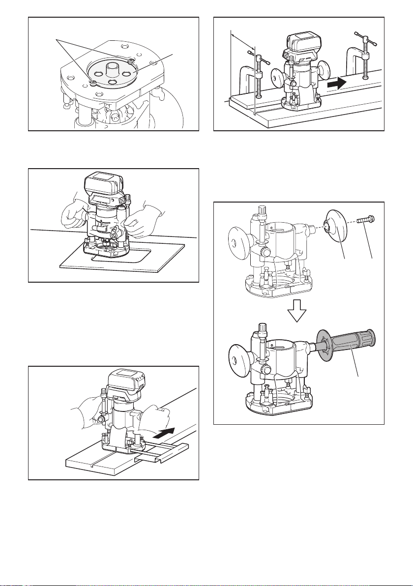
37 ESPAÑOL
1
2
►1.Tornillo2. Guía de plantilla
2. Opere la herramienta de la misma manera que la
guía de plantilla para la base de la recortadora.
Uso de la regla paralela
Lareglaparalelaresultaecazparahacercortes
rectosduranteelbiseladooelranurado.Ajusteladis-
tancia entre la fresa y la regla paralela. En la distancia
deseada,aprietelospernosdemariposaparajarla
regla paralela. Cuando corte, mueva la herramienta con
la regla paralela nivelada con el costado de la pieza de
trabajo.
Siladistancia(A)entreelcostadodelapiezadetra-
bajoylaposicióndecorteesmuyanchaparalaregla
paralela,osielcostadodelapiezadetrabajonoes
recto, no podrá utilizarse la regla paralela.
Enestecaso,sujetermementeunatablarectaala
piezadetrabajoyutilícelacomoguíacontralabasede
inmersión.Avancelaherramientaenladireccióndela
echa.
A
Cambio de la empuñadura tipo perilla
a la empuñadura tipo barra
Para instalar la empuñadura tipo barra en la base de
inmersión,aojeeltornillodelaempuñaduratipoperi-
lla, luego retire la empuñadura tipo perilla y después
instale la empuñadura tipo barra apretándola.
12
3
►1. Empuñadura tipo perilla 2.Tornillo
3. Empuñadura tipo barra

38 ESPAÑOL
MANTENIMIENTO
PRECAUCIÓN: Asegúrese siempre de que la
herramienta esté apagada y el cartucho de batería
extraído antes de intentar realizar una inspección
o mantenimiento.
AVISO: Nunca use gasolina, bencina, diluyente
(tíner), alcohol o sustancias similares. Puede que
esto ocasione grietas o descoloramiento.
ParamantenerlaSEGURIDADyFIABILIDADdelpro-
ducto, las reparaciones, y cualquier otra tarea de man-
tenimientooajustedeberánserrealizadasencentros
de servicio autorizados o de fábrica Makita, empleando
siempre repuestos Makita.
ACCESORIOS
OPCIONALES
PRECAUCIÓN: Estos accesorios o aditamen-
tos están recomendados para utilizarse con su
herramienta Makita especicada en este manual.
El empleo de cualquier otro accesorio o aditamento
puede conllevar el riesgo de lesiones personales.
Utilice los accesorios o aditamentos solamente para
sunestablecido.
Si necesita cualquier ayuda para más detalles en
relaciónconestosaccesorios,pregunteasucentrode
servicio local Makita.
• Fresasrectasydeformaciónderanuras
• Fresasdeformacióndebordes
• Fresasderecortedelaminados
• Conjuntodelaguíarecta
• Conjuntodelaguíaderecorte
• Conjuntodelabasedelarecortadora
• Conjuntodelabasedeinmersión
• Conjuntodelabasedescentrada
• Accesoriodelaempuñadura
• Guíadeplantilla
• Conodesujeciónde1/4″
• Conodesujeciónde3/8″
• Llave13
• Llave22
• Makitagenuinebatteryandcharger
NOTA:Algunosdelosartículosenlalistapueden
incluirse en el paquete de la herramienta como acce-
sorios estándar. Éstos pueden variar de país a país.
GARANTÍA LIMITADA DE UN AÑO
DE MAKITA
Ésta Garantía no aplica para México
Política de garantía
Cada herramienta Makita es inspeccionada y probada
exhaustivamente antes de salir de la fábrica. Se garan-
tiza que está libre de defectos de mano de obra y mate-
rialesporelperíododeUNAÑOapartirdelafechaori-
ginal de compra. Si durante este período de un año se
desarrollara algún problema, devuelva la herramienta
COMPLETA,conelenvíoprepagado,auncentrode
servicioautorizadoodefábricaMakita.Silainspección
muestra que el problema ha sido a causa de un defecto
demanodeobraomaterial,Makitaharálareparación
(oasudiscreción,elreemplazo)sinningúncargo.
Esta garantía no aplica cuando:
• lasreparacionessehayanhechoointentado
hacer por otros;
• serequieranreparacionesdebidoaldesgaste
normal;
•
la herramienta haya sido maltratada, recibido un mal
uso o haya recibido un mantenimiento inapropiado;
• sehayanhechomodicacionesalaherramienta.
ENNINGÚNCASOMAKITASEHARÁ
RESPONSABLEDENINGÚNDAÑOINDIRECTO,
INCIDENTAL,ODERIVADODELAVENTAO
USODELPRODUCTO.ESTEDESCARGODE
RESPONSABILIDADAPLICADURANTEYDESPUÉS
DELPLAZODEESTAGARANTÍA.
MAKITARENUNCIAALARESPONSABILIDADPOR
CUALQUIERGARANTÍAIMPLÍCITA,INCLUYENDO
GARANTÍASDE“COMERCIABILIDAD”Y
“ADECUACIÓNPARAUNPROPÓSITOESPECÍFICO”,
DESPUÉSDELPLAZODEUNAÑODEESTA
GARANTÍA.
Estagarantíaleconcedederechoslegalesespecícos
y usted podrá tener también otros derechos que varían
deunestadoaotro.Algunosestadosnopermitenla
exclusiónolimitacióndedañosincidentalesocon-
secuentes,porloquelalimitaciónoexclusiónarriba
mencionadapodríanoaplicarparausted.Algunos
estadosnopermitenlalimitaciónsobreladuraciónde
unagarantíaimplícita,porloquelalimitaciónarriba
mencionada podría no aplicar para usted.

39

Some dust created by power sanding, sawing, grinding, drilling, and other
construction activities contains chemicals known to the State of California
to cause cancer, birth defects or other reproductive harm. Some examples
of these chemicals are:
• lead from lead-based paints,• crystalline silica from bricks and cement and other masonry products, and• arsenic and chromium from chemically-treated lumber.
Your risk from these exposures varies, depending on how often you do this
type of work. To reduce your exposure to these chemicals: work in a well
ventilated area, and work with approved safety equipment, such as those
dust masks that are specially designed to filter out microscopic particles.
WARNING
< USA only >
ADVERTENCIA
Algunos polvos creados por el lijado, aserrado, esmerilado, taladrado y
otras actividades de la construcción contienen sustancias químicas
reconocidas por el Estado de California como causantes de cáncer, defectos
de nacimiento y otros peligros de reproducción. Algunos ejemplos de estos
productos químicos son:
• plomo de pinturas a base de plomo,• sílice cristalino de ladrillos y cemento y otros productos de albañilería, y
• arsénico y cromo de maderas tratadas químicamente.El riesgo al que se expone varía, dependiendo de la frecuencia con la que
realice este tipo de trabajo. Para reducir la exposición a estos productos
químicos: trabaje en un área bien ventilada y póngase el equipo de seguridad
indicado, tal como las máscaras contra polvo que están especialmente
diseñadas para filtrar partículas microscópicas. < Sólo en los Estados Unidos >
Makita Corporation
3-11-8, Sumiyoshi-cho,Anjo, Aichi 446-8502 Japan
www.makita.com
885585C942
XTR01-1
EN, ESMX
20170215