YOUR ULTIMATE POWER TOOL PARTNER
MADE IN CHINA
Model: MFIF003
www.mellif-tools.com
WARNING :
To reduce risk of injury,user must read and understand
Instruction manual.
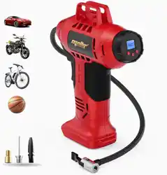
AUTO INFLATOR
2
TABLE OF CONTENTS
PRODUCT SPECIFICATIONS
3URGXFW6SHFL¿FDWLRQV ................................................................................................. 2
Package Contents ....................................................................................................... 3
Symbols ..................................................................................................................... 4
Safety Information ...................................................................................................... 5
Assembly Instructions .................................................................................................. 7
Operating Instructions ................................................................................................. 9
Care and Maintenance............................................................................................... 10
Troubleshooting ......................................................................................................... 10
Warranty .................................................................................................................. 10
Replacement Parts List ...............................................................................................11
SPECIFICATIONS
Voltage 20V
Max working pressure 160 PSI
Weight without battery 1.97 kg
Item Temperature
Appliance Storage Temperature Range Û)Û&aÛ)Û&
Appliance Operation Temperature Range Û)Û&aÛ)Û&
Battery Charging Temperature Range Û)Û&aÛ)Û&
Charger Operation Temperature Range Û)Û&aÛ)Û&
Battery Storage Temperature Range Û)Û&aÛ)Û&
Battery Discharging temperature Range Û)Û&aÛ)Û&
The recommended ambient temperature range:
18V
3
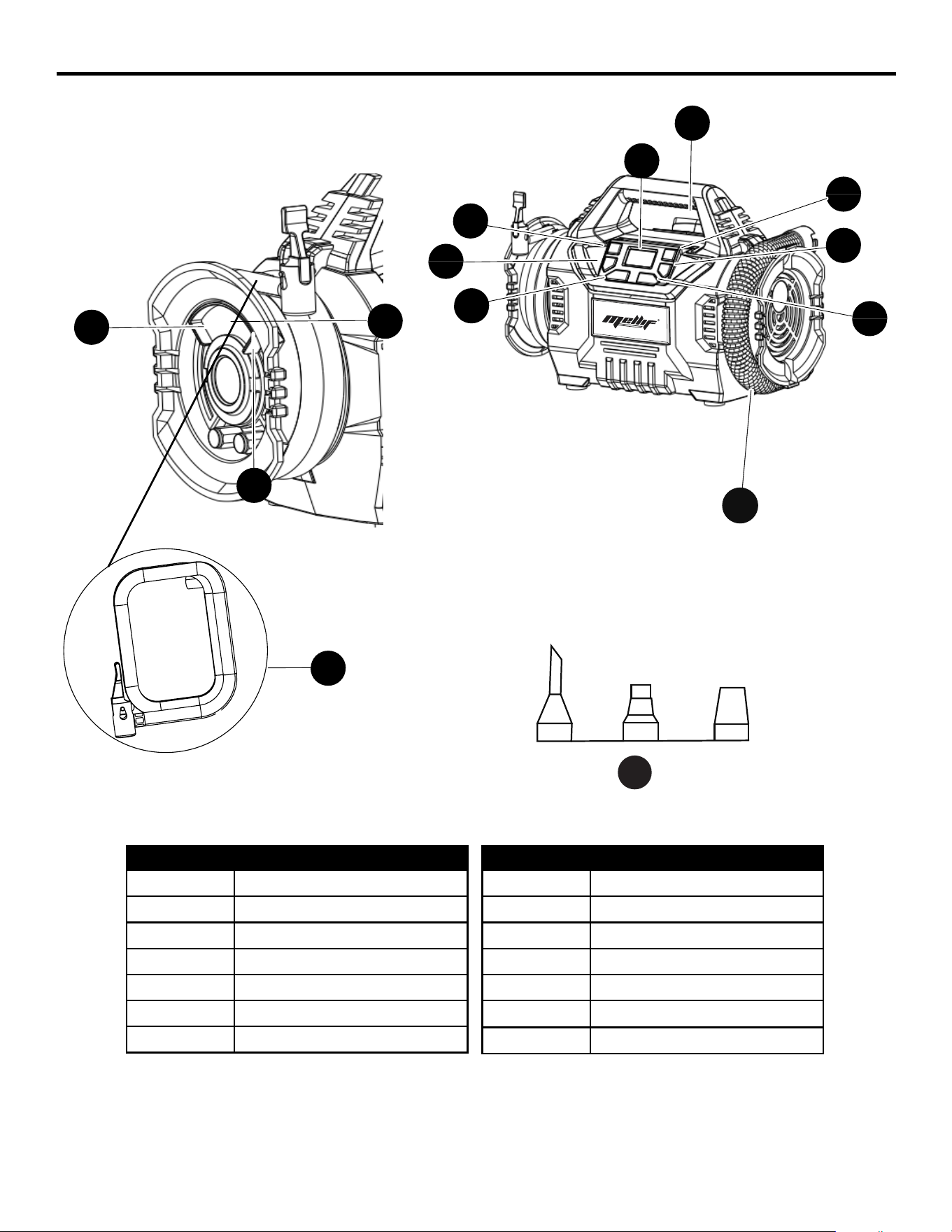
PART DESCRIPTION
A Carrying handle
B (+) Increase PSI button
C (-) Decrease PSI button
D Mode selection button
E ON/OFF button
F Run/Pause button
G LED light button
PACKAGE CONTENTS
B
H
A
G
F
E
C
D
M
L
K
J
I
PART DESCRIPTION
H Digital pressure gauge
I Sports needle
J Presta valve adaptor
K Air hose (low pressure)
L
Raft nozzle
M
••••••••
logo
Air hose ( high pressure)
••••
••••••••••••••••••••••
N Large-volume nozzles
K
N
4
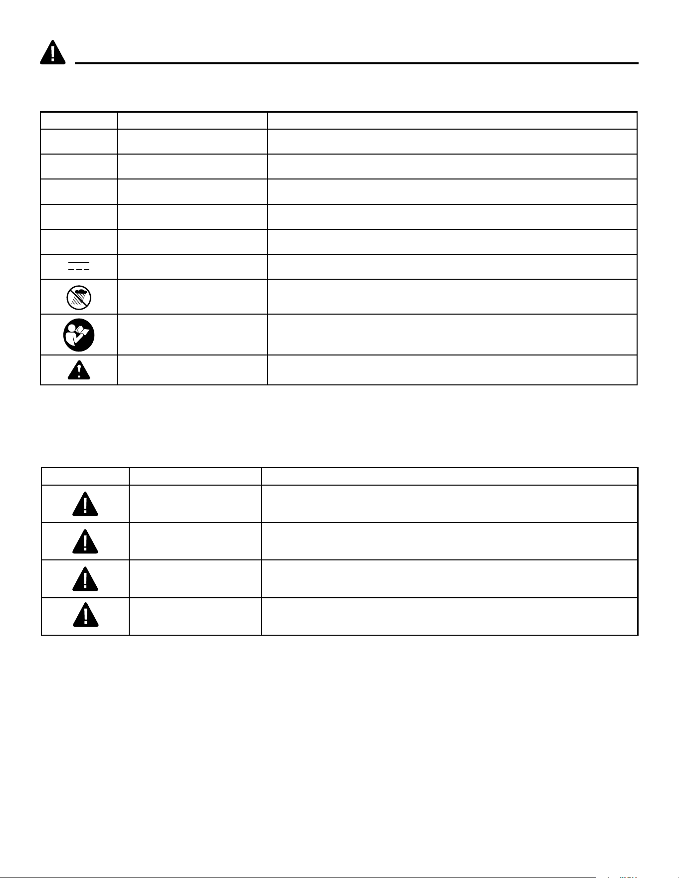
SYMBOLS
Some of the following symbols may be used on this product. Please study them and learn their
meaning. Proper interpretation of these symbols will allow you to operate the product better and safer.
SYMBOLS NAME DESIGNATION/EXPLANATION
V Volts Voltage
A Amperes Current
Hz Hertz Frequency (cycles per second)
Wh Watt Hour Energy Storage Capacity
Ah Amp Hour Current Capacity
Direct Current Type or a characteristic of current
Wet Conditions Alert Do not expose to rain or use in damp locations.
Read The Operator’s
Manual
To reduce the risk of injury, user must read and understand
operator’s manual before using this product.
Safety Alert Precautions that involve your safety.
The following signal words and meanings are intended to explain the levels of risk associated with
this product.
SYMBOL SIGNAL MEANING
DANGER
Indicates an imminently hazardous situation, which, if not
avoided, will result in death or serious injury.
WARNING
Indicates a potentially hazardous situation, which, if not
avoided, could result in death or serious injury.
CAUTION
Indicates a potentially hazardous situation, which, if not
avoided, may result in minor or moderate injury.
CAUTION
(Without Safety Alert Symbol) Indicates a situation that may
result in property damage.

5
WARNING: IMPORTANT SAFETY INSTRUCTIONS
SAFETY INFORMATION
Read and understand all instructions before using this product. Failure to follow all instructions listed
EHORZPD\UHVXOWLQHOHFWULFVKRFN¿UHDQGRUVHULRXVSHUVRQDOLQMXU\
• For household use only.
6HUYLFLQJRIDQLQÀDWRUUHTXLUHVH[WUHPHFDUHDQGNQRZOHGJHRIWKHV\VWHPDQGVKRXOGEHGRQH
RQO\E\TXDOL¿HGVHUYLFHSHUVRQQHO5HSODFHPHQWSDUWVIRUDQLQÀDWRUPXVWEHLGHQWLFDOWRWKRVH
SDUWVLQWKHLQÀDWRU
6WRUHLQÀDWRULQGRRUVZKHQQRWLQXVH
Keep out of reach of children.
'RQRWFOHDQWKLVLQÀDWRUZLWKDZDWHUVSUD\RUWKHOLNH)ROORZPDQXIDFWXUHUVFOHDQLQJLQVWUXFWLRQV
'LVFRQQHFWWKHEDWWHU\SDFNIURPWKHLQÀDWRUEHIRUHPDNLQJDQ\DGMXVWPHQWVFKDQJLQJDFFHVVRULHV
RUVWRULQJLQÀDWRUVHWF
6WRUHLGOHLQÀDWRUVRXWRIWKHUHDFKRIFKLOGUHQDQGGRQRWDOORZSHUVRQVXQIDPLOLDUZLWKWKHLQÀDWRU
RUWKHVHLQVWUXFWLRQVWRRSHUDWHWKHLQÀDWRU,QÀDWRUVDUHGDQJHURXVLQWKHKDQGVRIXQWUDLQHGXVHUV
+DYH\RXULQÀDWRUVHUYLFHGE\DTXDOL¿HGUHSDLUSHUVRQXVLQJRQO\LGHQWLFDOUHSODFHPHQWSDUWV7KLV
ZLOOHQVXUHWKDWWKHVDIHW\RIWKHLQÀDWRULVPDLQWDLQHG
Battery disposal should be in compliance with the local regulations that address the disposal of
hazardous materials, and do not incinerate battery pack.
Keep your work area clean and well lit. Cluttered benches and dark areas increase the possibility of
personal injury or property damage.
'RQRWRSHUDWHLQÀDWRUVLQH[SORVLYHDWPRVSKHUHVVXFKDVLQWKHSUHVHQFHRIÀDPPDEOHOLTXLGV
gases or dust.
.HHSE\VWDQGHUVFKLOGUHQDQGYLVLWRUVDZD\ZKLOHRSHUDWLQJDLQÀDWRU'LVWUDFWLRQVFDQFDXVH\RX
to lose control.
)RUEHVWUHVXOWVDQGPRUHHI¿FLHQWSRZHULWLVUHFRPPHQGHGWKDW\RXRSHUDWH\RXULQÀDWRUZLWK\RXU
vehicle's engine running, making absolutely sure you are outside or in an open, well-ventilated area
DQGQRWLQVLGHDFRQ¿QHGDUHDVXFKDVDJDUDJHDVERGLO\LQMXU\RUDVSK\[LDWLRQUHVXOWLQJLQGHDWK
could occur.
7KLVLQÀDWRULVGHVLJQHGWRLQÀDWHFDUWLUHVELNHWLUHV$79WLUHVVSRUWVHTXLSPHQWDLUPDWWUHVVHV
EHDFKWR\VDQGRWKHULQÀDWDEOHV'RQRWXVHIRUDQ\SXUSRVHRWKHUWKDQLQÀDWLQJ,I\RXGRVRERGLO\
harm or personal injury can occur.
$OORZLQÀDWRUWRFRROGRZQPLQXWHVDIWHUHDFKPLQXWHVRIFRQWLQXRXVRSHUDWLRQ
'RQRWFDUU\LQÀDWRUE\WKHDLUKRVHDVGDPDJHPD\RFFXU
'RQRWOHDYHWKHLQÀDWRUXQDWWHQGHGZKLOHLQRSHUDWLRQ
'RQRWRYHULQÀDWH3OHDVHIROORZWKHPDQXIDFWXUHU¶VLQVWUXFWLRQVIRUWKHLWHP\RXDUHLQÀDWLQJ
.HHSWKHLQÀDWRUDZD\IURPÀDPPDEOHDUHDVOLTXLGVDWDOOWLPHV
'RQRWRSHUDWHWKHLQÀDWRULQZHWRUGDPSDUHDV
2SHUDWHWKHLQÀDWRURQO\ZLWKWKHDWWDFKPHQWVWKDWDUHLQFOXGHG
Use safety glasses. Also use a face or dust mask if operation is dusty.
7KLVLQÀDWRULVQRWGHVLJQHGWR¿OODLUWDQNVRUDLUVKRFNV
•
•
•
•
•
•
•
•
•
•
•
•
•
•
•
•
•
•
•
•
•
•

6
SAFETY INFORMATION
• Prevent unintentional starting. Ensure the switch is in the off-position before connecting to battery
SDFNSLFNLQJXSRUFDUU\LQJWKHHTXLSPHQW&DUU\LQJWKHHTXLSPHQWZLWK\RXU¿QJHURQWKHVZLWFKRU
energizing equipment that have the switch on invites accidents.
• Disconnect the battery pack from the equipment before making any adjustments, changing
accessories, or storing equipment. Such preventive safety measures reduce the risk of starting the
equipment accidentally.
• 5HFKDUJHRQO\ZLWKWKHFKDUJHUVSHFL¿HGE\WKHPDQXIDFWXUHU$FKDUJHUWKDWLVVXLWDEOHIRURQH
W\SHRIEDWWHU\SDFNPD\FUHDWHDULVNRI¿UHZKHQXVHGZLWKDQRWKHUEDWWHU\SDFN
• 8VHHTXLSPHQWRQO\ZLWKVSHFL¿FDOO\GHVLJQDWHGEDWWHU\SDFNV8VHRIDQ\RWKHUEDWWHU\SDFNVPD\
FUHDWHDULVNRILQMXU\DQG¿UH
• When battery pack is not in use, keep it away from other metal objects like paper clips, coins, keys,
nails, screws or other small metal objects that can make a connection from one terminal to another.
• 6KRUWLQJWKHEDWWHU\WHUPLQDOVWRJHWKHUPD\FDXVHEXUQVRUD¿UH
• Under abusive conditions, liquid may be ejected from the battery; avoid contact. If contact
DFFLGHQWDOO\RFFXUVÀXVKZLWKZDWHU,IOLTXLGFRQWDFWVH\HVDGGLWLRQDOO\VHHNPHGLFDOKHOS/LTXLG
ejected from the battery may cause irritation or burns.
• 'RQRWXVHDEDWWHU\SDFNRUHTXLSPHQWWKDWLVGDPDJHGRUPRGL¿HG'DPDJHGRUPRGL¿HG
EDWWHULHVPD\H[KLELWXQSUHGLFWDEOHEHKDYLRUUHVXOWLQJLQ¿UHH[SORVLRQRUULVNRILQMXU\
• 'RQRWH[SRVHDEDWWHU\SDFNRUHTXLSPHQWWR¿UHRUH[FHVVLYHWHPSHUDWXUH([SRVXUHWR¿UHRU
temperature above 265°F (130°C) may cause an explosion.
• +DYHVHUYLFLQJSHUIRUPHGE\DTXDOL¿HGUHSDLUSHUVRQXVLQJRQO\LGHQWLFDOUHSODFHPHQWSDUWV7KLV
will ensure that the safety of the product is maintained.
• Follow all charging instructions and do not charge the battery pack or appliance outside of the
WHPSHUDWXUHUDQJHVSHFL¿HGLQWKHLQVWUXFWLRQV&KDUJLQJLPSURSHUO\RUDWWHPSHUDWXUHVRXWVLGHRI
WKHVSHFL¿HGUDQJHPD\GDPDJHWKHEDWWHU\DQGLQFUHDVHWKHULVNRI¿UH
• Do not modify or attempt to repair the appliance or the battery pack except as indicated in the
instructions for use and care.
ELECTRICAL
GENERAL SAFETY RULES
• 9HULI\WKDWWKHLQÀDWRULVVHFXUHZKLOHWUDQVSRUWLQJ
• 6WRUHWKHLQÀDWRULQDGU\DUHDWKDWZLOOSUHYHQWXQDXWKRUL]HGXVHRUGDPDJH.HHSRXWRIWKHUHDFK
of children.
• .HHSKDQGOHVGU\FOHDQDQGIUHHRIGHEULV&OHDQWKHLQÀDWRUDIWHUHDFKXVH5HIHUWRWKH
Maintenance Section in this manual for more information.
• Keep these instructions in a safe place for future reference. Refer to them often and use them to
LQVWUXFWRWKHUXVHUV$Q\RQHZKRXVHVWKLVLQÀDWRUPXVWUHDGWKHVHLQVWUXFWLRQVFDUHIXOO\
7
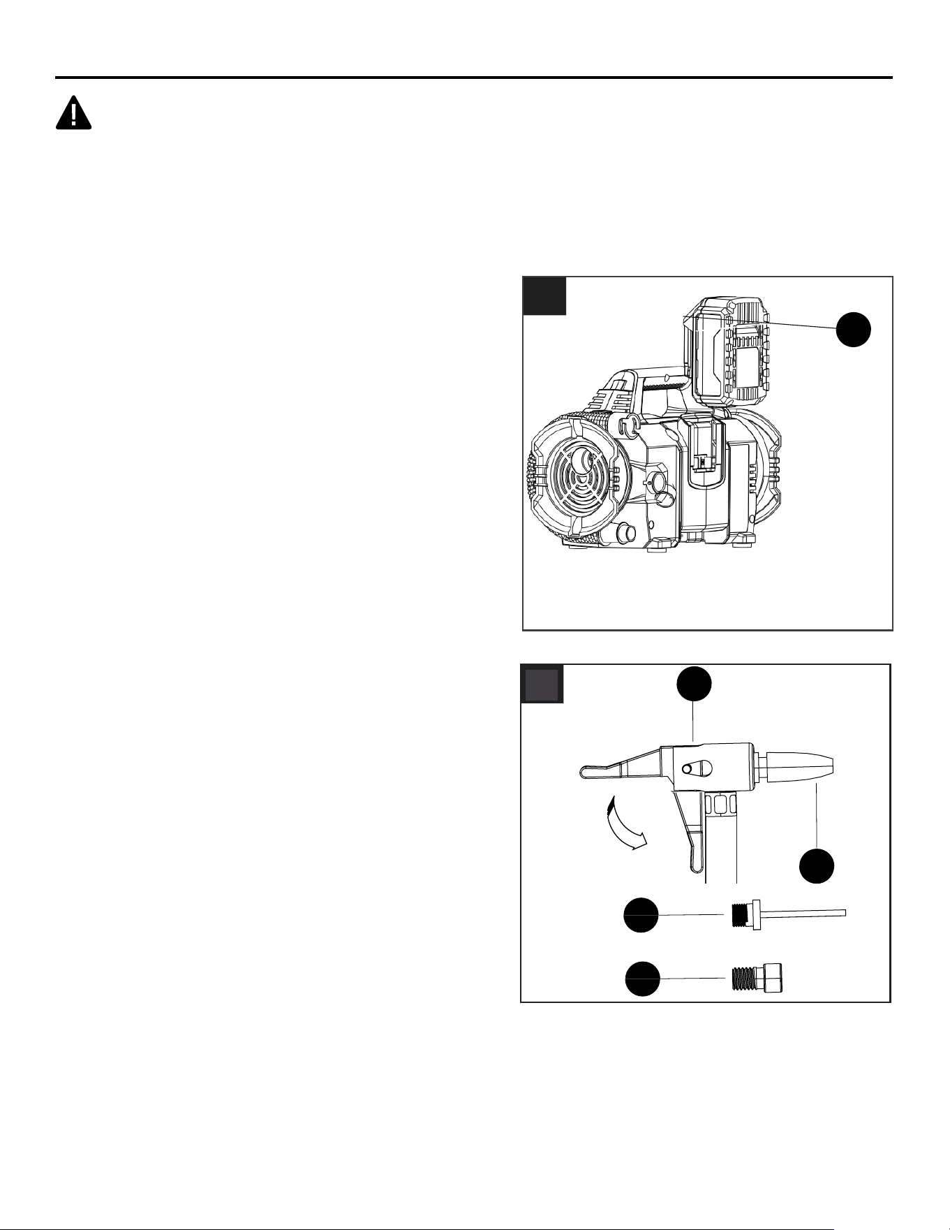
1. Battery Mode
Battery Installation and Removal
• Install the battery pack by aligning the battery
(not included) with the battery opening.
Insert the battery into the battery opening until
the battery release button (O) locks into place.
Push down on the battery until it locks into place.
You should hear a “click” once it is installed.
To remove the battery pack, press the battery
release button (O) and pull up on the battery pack
WRUHPRYHLWIURPWKHLQÀDWRU
•
•
•
WARNING
• Do not allow familiarity with this product to make you careless. Remember that a careless fraction
RIDVHFRQGLVVXI¿FLHQWWRLQÀLFWVHULRXVLQMXU\
• Do not use any attachments or accessories not recommended by the manufacturer of this product.
The use of attachments or accessories not recommended can result in serious personal injury.
• 'HYLDWLRQIURPWKHDVVHPEO\LQVWUXFWLRQPD\UHVXOWLQDULVNRI¿UHRUHOHFWULFVKRFN
ASSEMBLY INSTRUCTIONS
O
1
8
ASSEMBLY INSTRUCTIONS
P
I
J
L
3
K
K
5
Q
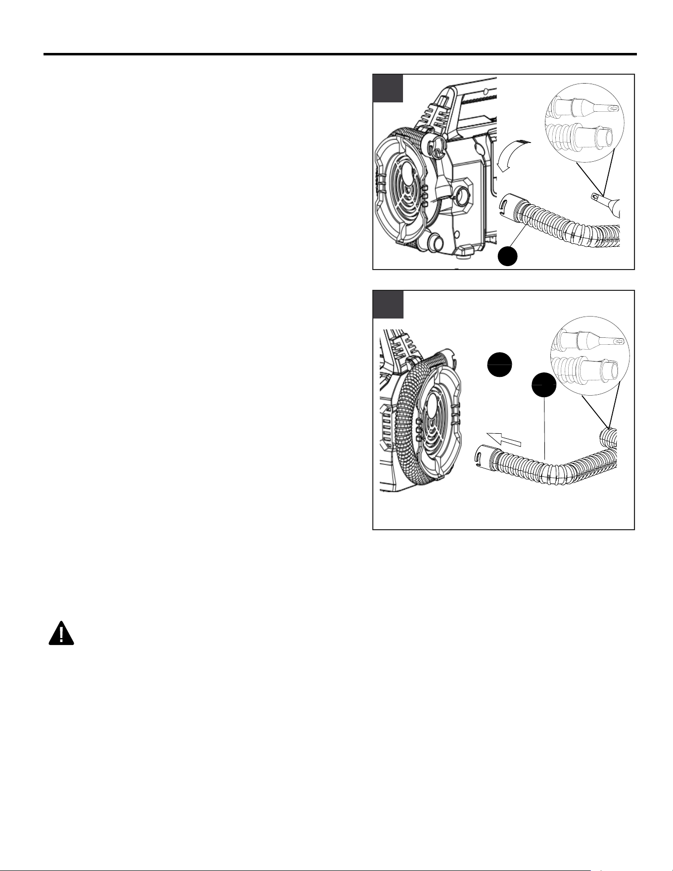
4. Low Pressure Mode
• Insert low pressure air hose (K) to the connector
port and rotate counterclockwise.
• 8VH\RXUGHVLUHGQR]]OHWRLQÀDWHWKHLWHP
Note: Choose the low pressure mode to start the
LQÀDWRUZKHQ\RXFRQQHFWWKHair hose (low pressure)
to the item.
5. 'HÀDWLQJ0RGH
• 7RGHÀDWLQJLWHPLQVHUWORZSUHVVXUHDLUKRVH.
to the air outlet (Q).
• 8VH\RXUGHVLUHGQR]]OHWRGHÀDWHWKHLWHP
Note6HWWKHLQÀDWRUWRORZSUHVVXUHPRGHWRGHÀDWH
3. High Pressure Mode
• Connect the quick connect valve adaptor (P) to
LWHP\RXDUHLQÀDWLQJDQGSXVKGRZQWKHYDOYH
lock lever to secure the connection.
Note: Choose the high pressure mode to start the
LQÀDWRUZKHQ\RXFRQQHFWWKHair hose (high pressure)
to the item.
4
2.
2
8
ASSEMBLY INSTRUCTIONS
P
I
J
L
3
K
K
5
Q
4. Low Pressure Mode
• Insert low pressure air hose (K) to the connector
port and rotate counterclockwise.
• 8VH\RXUGHVLUHGQR]]OHWRLQÀDWHWKHLWHP
Note: Choose the low pressure mode to start the
LQÀDWRUZKHQ\RXFRQQHFWWKHair hose (low pressure)
to the item.
5. 'HÀDWLQJ0RGH
• 7RGHÀDWLQJLWHPLQVHUWORZSUHVVXUHDLUKRVH.
to the air outlet (Q).
• 8VH\RXUGHVLUHGQR]]OHWRGHÀDWHWKHLWHP
Note6HWWKHLQÀDWRUWRORZSUHVVXUHPRGHWRGHÀDWH
3. High Pressure Mode
• Connect the quick connect valve adaptor (P) to
LWHP\RXDUHLQÀDWLQJDQGSXVKGRZQWKHYDOYH
lock lever to secure the connection.
Note: Choose the high pressure mode to start the
LQÀDWRUZKHQ\RXFRQQHFWWKHair hose (high pressure)
to the item.
4
9
OPERATING INSTRUCTIONS
G
F
E
D
B
C
H
6
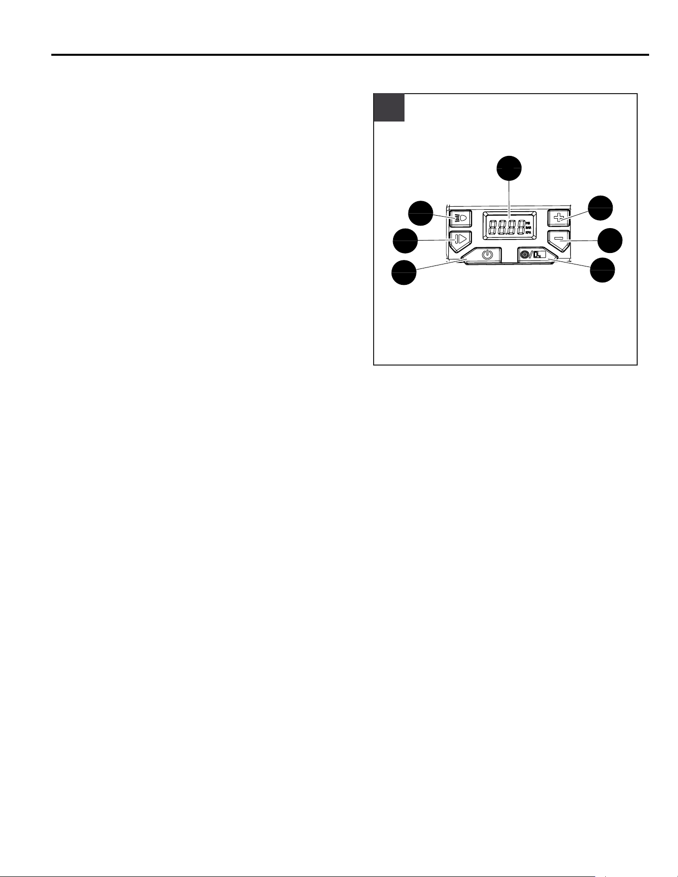
6WDUWLQJDQG6WRSSLQJWKH,QÀDWRU
WARNING
$OZD\VDYRLGRYHULQÀDWLRQDQGQHYHUOHDYHWKH
LQÀDWRUXQDWWHQGHGZKHQLQXVH
• Press the On/Off button (E).
• Push the mode selection button (D) to choose
high pressure or low pressure mode.
• The digital pressure gauge (H) will display the
current pressure (in 1 PSI increments) of the item
\RXDUHLQÀDWLQJRQWKHXSSHUVHFWLRQRIWKH/&'
Screen.
• Press button (B) to increase PSI, or press button
(C) to decrease PSI.
• 7RVWDUWWKHLQÀDWRUSXVKWKHUXQSDXVHEXWWRQ).
• To change the target PSI level, push the Run/
Pause button (F) again and the adjust level.
• 7RVWRSWKHLQÀDWRUEHIRUHLWUHDFKHVWKHWDUJHW36,
level, push the run/pause button (F). To resume
LQÀDWLRQVLPSO\SUHVVWKHEXWWRQDJDLQ3UHVVWKH
2Q2IIEXWWRQ%WRWXUQWKHLQÀDWRURII7KHSRZHU
automatically cycles off after three minutes of no
activity.
Note:
• When the LCD readout screen is displaying the
WDUJHW36,WKH/&'UHDGRXWZLOOÀDVKWLPHVDW
the desired preset level.
• The pressure value of the low pressure mode is
¿[HGDQGFDQQRWEHDGMXVWHG.
• 7KHLQÀDWRUZLOOVKXWRIIDXWRPDWLFDOO\DW
the desired target PSI level that you have
programmed into the target PSI setting.
• 7KHLQÀDWRUKDVDWROHUDQFHRI36,DQGZLOO
automatically shut off accordingly.
• ,IWKHFXUUHQWSUHVVXUHRIWKHLWHP\RXDUHLQÀDWLQJ
LVJUHDWHUWKDQWKHWDUJHW36,WKHLQÀDWRUZLOOQRW
turn on.
3.
4.
5.
3
4
9
OPERATING INSTRUCTIONS
G
F
E
D
B
C
H
6
6WDUWLQJDQG6WRSSLQJWKH,QÀDWRU
WARNING
$OZD\VDYRLGRYHULQÀDWLRQDQGQHYHUOHDYHWKH
LQÀDWRUXQDWWHQGHGZKHQLQXVH
• Press the On/Off button (E).
• Push the mode selection button (D) to choose
high pressure or low pressure mode.
• The digital pressure gauge (H) will display the
current pressure (in 1 PSI increments) of the item
\RXDUHLQÀDWLQJRQWKHXSSHUVHFWLRQRIWKH/&'
Screen.
• Press button (B) to increase PSI, or press button
(C) to decrease PSI.
• 7RVWDUWWKHLQÀDWRUSXVKWKHUXQSDXVHEXWWRQ).
• To change the target PSI level, push the Run/
Pause button (F) again and the adjust level.
• 7RVWRSWKHLQÀDWRUEHIRUHLWUHDFKHVWKHWDUJHW36,
level, push the run/pause button (F). To resume
LQÀDWLRQVLPSO\SUHVVWKHEXWWRQDJDLQ3UHVVWKH
2Q2IIEXWWRQ%WRWXUQWKHLQÀDWRURII7KHSRZHU
automatically cycles off after three minutes of no
activity.
Note:
• When the LCD readout screen is displaying the
WDUJHW36,WKH/&'UHDGRXWZLOOÀDVKWLPHVDW
the desired preset level.
• The pressure value of the low pressure mode is
¿[HGDQGFDQQRWEHDGMXVWHG.
• 7KHLQÀDWRUZLOOVKXWRIIDXWRPDWLFDOO\DW
the desired target PSI level that you have
programmed into the target PSI setting.
• 7KHLQÀDWRUKDVDWROHUDQFHRI36,DQGZLOO
automatically shut off accordingly.
• ,IWKHFXUUHQWSUHVVXUHRIWKHLWHP\RXDUHLQÀDWLQJ
LVJUHDWHUWKDQWKHWDUJHW36,WKHLQÀDWRUZLOOQRW
turn on.
5

10
CARE AND MAINTENANCE
WARNING
$OOPDLQWHQDQFHVKRXOGEHFDUULHGRXWE\DTXDOL¿HGUHSDLUSHUVRQ
When servicing, use only identical replacement parts. Use of any other part could create a hazard or
cause product damage.
Cleaning
%HIRUHFOHDQLQJRUSHUIRUPLQJDQ\PDLQWHQDQFHUHPRYHWKHEDWWHU\IURPWKHLQÀDWRU8VHFOHDQ
cloths to remove dirt, dust, oil, grease, etc. Always use only a soft, dry cloth to clean the plastic parts,
never use detergent or alcohol. Always wear safety goggles when cleaning tools with compressed air.
TROUBLESHOOTING
PROBLEM POSSIBLE CAUSE CORRECTIVE ACTION
7KHLQÀDWRUGRHV
not work.
Low battery charge. Charge the battery pack.
The fan has stopped working to
protect internal circuits.
7XUQRIIWKHLQÀDWRUZDLWIRUWKHWRRODQG
battery to cool down, then and start the tool
again.
WARRANTY
1 - YEAR LIMITED WARRANTY
7KLV,QÀDWRULVZDUUDQWHGWRWKHRULJLQDOSXUFKDVHUIURPWKHRULJLQDOSXUFKDVHGDWHIRU\HDUsubj
ect to
the warranty coverage described herein.
7KLV,QÀDWRUZDUUDQWHGIRUWKHRULJLQDOXVHUWREHIUHHIURPGHIHFWVLQPDWHULDODQGZRUNPDQVKLS
,I\RXEHOLHYHWKDWWKH,QÀDWRULVGHIHFWLYHDWDQ\WLPHGXULQJWKHVSHFL¿HGZDUUDQW\SHULRGVLPSO\UHWXU
Q WKH ,QÀDWRU DORQJ ZLWK SURRI RI SXUFKDVH WR WKH SODFH RI SXUFKDVH IRU D IUHH UHSODFHPHQW RUrefu
nd.
This warranty is void if: defects in materials or workmanship or damages result from repairs or
alterations which have been made or attempted by others or the unauthorized use of nonconforming
parts; the damage is due to normal wear, damage is due to abuse (including overloading of the tool
beyond capacity), improper maintenance, neglect or accident; or the damage is due to the use of the
tool after partial failure or use with improper accessories or unauthorized repair or alteration.
7KLVZDUUDQW\JLYHV\RXVSHFL¿FOHJDOULJKWVDQG\RXPD\DOVRKDYHRWKHUULJKWVWKDWYDU\IURPVWDWHWR
state.
11
REPLACEMENT PARTS LIST
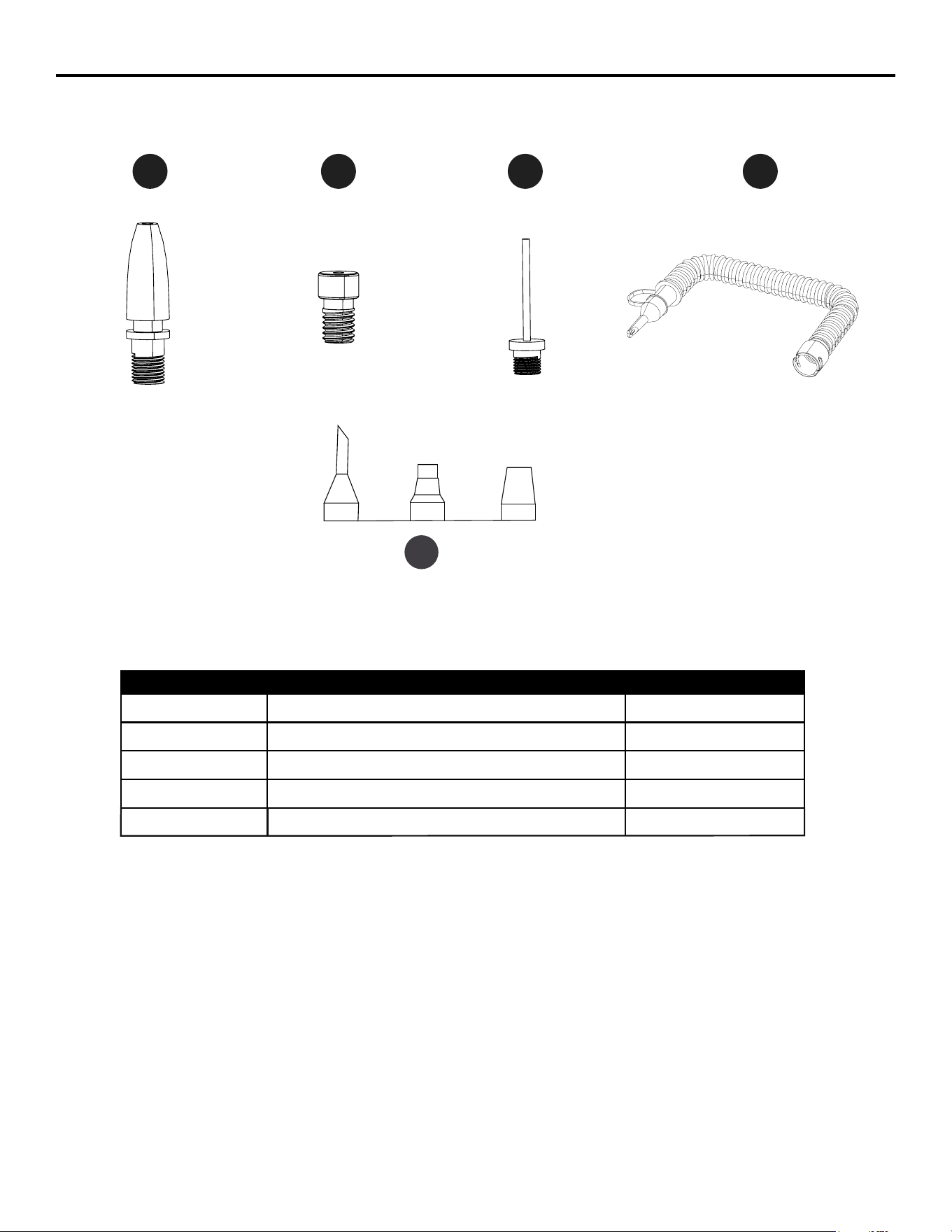
PART DESCRIPTION
L Raft nozzle x1
J Presta valve adaptor x1
I Sports needle x1
K Air hose (low pressure) x1
L
J
I
K
11
REPLACEMENT PARTS LIST
PART DESCRIPTION
L Raft nozzle x1
J Presta valve adaptor x1
I Sports needle x1
K Air hose (low pressure) x1
L
J
I
K
N
N
Large-volume nozzles
x1