

Operator’s Manual
www.mechmaxx.com
WARRANTY


TABLE OF CONTENTS
TABLE OF CONTENTS
SPECIFICATIONS
SAFETY SIGNS
SAFETY
1
2
BEFORE EVERY USE
7
EVERY WEEK
7
AFTER EVERY SEASON
7
CUTTING TEETH REMOVAL AND REPLACEMENT
7
LUBRICATION
7
HYDRAULIC SYSTEM
8
BOLT TORQUE
8
ENGLISH TORQUE SPECIFICATIONS
8
METRIC TORQUE SPECIFICATIONS
9
YOUR SAFETY
GENERAL SAFETY
AVOID ROLLOVER
4
4
4
PTO SHAFT
4
REQUIRED EQUIPMENT OF THE TRACTOR
5
PTO SHAFT ADJUSTMENT
5
TRACTOR MOUNTING
6
GRINDING OPERATION
6
3
4
OPERATION
5
7
MAINTENANCE
10
PARTS DIAGRAM
11
PARTS LIST
1
www.mechmaxx.com
TABLE OF CONTENTS

SPECIFICATIONS
2
www.mechmaxx.com
SPECIFICATIONS
Power Required
Hydraulic Flow Rate
Rotor Size
Carbide Steel Bolt-On Teeth
Required PTO Speed
Hydraulic Hose Length
Hydraulic Fittings Size
Cutting Height Above
Cutting Depth Below
Cutting Depth Per Pass
Swing Arc
Cutting Direction
3-Point Hitch
PTO Shaft
Dimensions (LxWxH)
Finish
Warranty
Weight (N.W./G.W.)
35-60 HP
5-13 GPM
24 in
16 (Replaceable)
540 RPM
6.6 ft
G1/2 in
18 in
12 in
6 in
40°
Horizontal and vertical
Category 1& 2
05B-LF-1600 With Slip Clutch 63-77 in
69 x 34 x 32in
Powder Coat Paint Galvanized Steel
1 year
684/750lbs
Model TSG61
3
www.mechmaxx.com
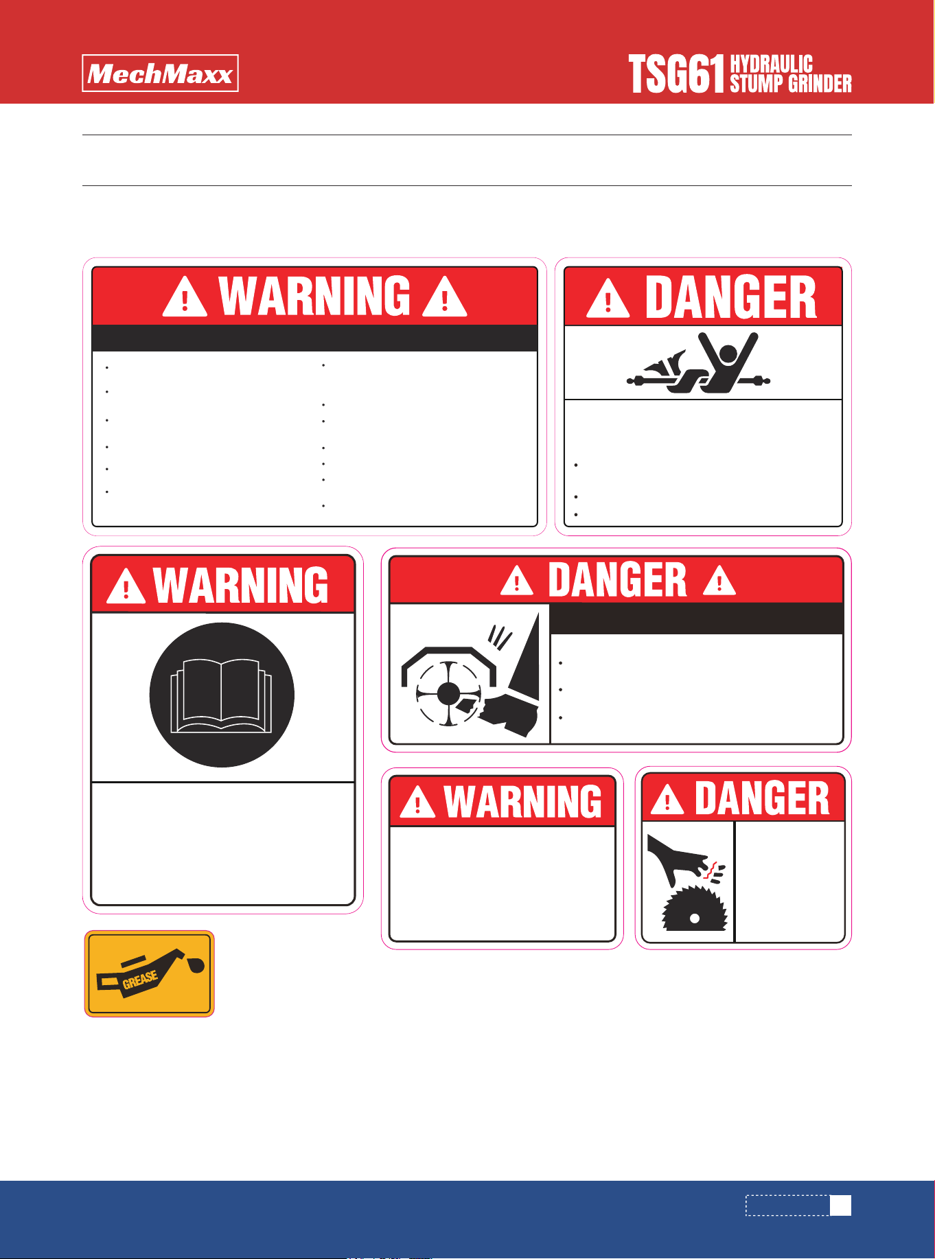
SAFETY SIGNS
The rating plate on your machine may show symbols. These represent important information about the product or instruc-
tions on its use.
SAFETY SIGNS
The PTO Driveline MUST be
measured and cut (if required) as
per the Owner's Manual.
Failure to do so will result in
damage to both the tractor
and the implement.
Read and understand
operators manual
before using this
machine.
ROTATING
BLADES
KEEP HANDS
AWAY
DO NOT go under frame when rotor is turning or engine
is running. Keep others away.
ROTATING KNIVES HAZARD
Disconnect & lockout power source BEFORE adjusting
or servicing.
Keep hands, feet, hair, and clothing away from moving
parts.
To prevent serious injury or death from rotating knives:
Read and understand Operator's manual
before using.
Operate with guards installed and in good
condition.
Operate only with tractor equipped with
ROPS and seatbelts.
Keep away from moving parts.
Stop engine, set brake and wait for all
moving parts to stop before dismounting.
Be sure lights and reflectors required by
law are clean and in good working order
before transporting.
Do not allow children to operate mower.
Travel with SMV and lights that follow local
codes.
Clean debris from mowing area.
Do not operate in the raised position.
Support securely before working beneath
unit.
Review safety instructions annually.
Do not permit riders on the tractor or
mower. Never carry child on tractor seat.
To Prevent Serious Injury Or Death:
All driveline guards, tractor, and equipment
shields in place.
ROTATING DRIVELINE CONTACT CAN
CAUSE DEATH KEEP AWAY!
DO NOT OPERATE WITHOUT :
Drivelines securely attached at both ends.
Driveline guards that turn freely on driveline.

4
www.mechmaxx.com
SAFETY
SAFETY
YOU are responsible for the SAFE operation and mainte-
nance of your MECHMAXX TSG61 Stump Grinder. YOU
must ensure that you and anyone else who is going to
use, maintain or work around the TSG61 Stump Grinder be
familiar with the operating and maintenance procedures
and related SAFETY information contained in this manual.
This manual will take you step-by-step through your work-
ing day and alerts you to all good safety practices that
should be used while followed the TSG61 Stump Grinder.
Remember, YOU are the key to safety. Good safety
practices not only protect you but also the people around
you. Make these practices a working part of your safety
program. Be certain that EVERYONE using this equip-
ment is familiar with the recommended using and mainte-
nance procedures and follows all the safety precautions.
Most accidents can be prevented. Do not risk injury or
death by ignoring good safety practices.
In order to prevent accidents carefully read and observe
the following instructions:
Use stump grinder only for the designed applications.
Any other use may result in personal injury, damage to
equipment and may void the warranty.
Verify stump grinder is locked to quick attach hitch before
operation or transport.
The equipment may rollover, resulting in death or serious
injury. To help prevent rollover:
Travel at a slow speed.
Avoid sharp turns & sudden movement on slopes.
Carry stump grinder close to the ground.
Avoid holes, ditches and other obstructions which may
cause equipment to rollover.
Use caution when operating on slopes and do not operate
on excessively steep slopes.
Do not exceed load capacity of equipment.
1. Only use PTO shafts recommended by the manufacturer
by the manufacturer.
2. The PTO shaft shielding (including guards and cones)
must be mounted on the machine and be in perfect condi-
tion.
3. Observe the recommended shielding position in trans-
port and working position.
4. The cardan shaft can only be connected or disconnect-
ed, when the tractor PTO is disengaged, the engine has
stopped and the ignition key has been removed.
5. The cardan shaft must always be properly mounted and
protected.
6. When disconnected, secure the PTO shaft to its holder
using the provided chain (or other means) to prevent
rotation or dragging.
7. Before s.engaging the tractor PTO make sure that the
chosen speed and direction of rotation match the speed
and rotation direction specified in the Specifications
section.
8. Before engaging the PTO make sure no person is stand-
ing in the danger area of the machine. This rule must also
be observed during machine operation.
9. Put the disconnected cardan shaft on the intended
holder.
Prevent serious injury or death.
Read and understand this manual before operating stump
grinder.
Always stop engine and remove key before leaving opera-
tor’s seat.
Never allow anyone near the stump grinder during opera-
tion.
Prevent serious injury or death from moving parts.
Moving parts can crush and dismember. Do not operate
without guards and shields in place.
Disconnect and lockout power source before adjusting or
performing maintenance.
YOUR SAFETY
GENERAL SAFETY
AVOID ROLLOVER
PTO SHAFT
5
www.mechmaxx.com
OPERATION
OPERATION
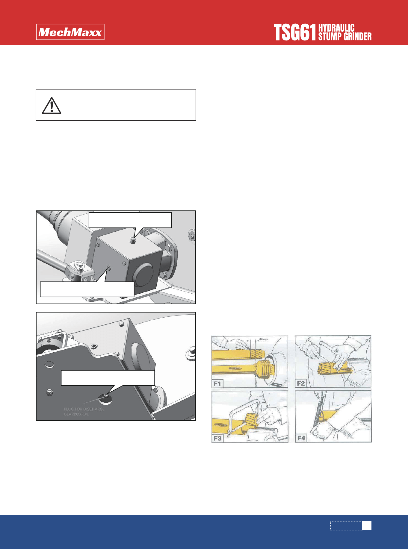
THE GEARBOX AND TRANSMISSION ARE SHIPPED WITH-
OUT OIL.
ADD OIL BEFORE FIRST USE!
Gear Oil SAE90 2200ml (approx. 2.3 US Quarts)
Check oil level in gearbox by removing the plug located on
the right-hand side. Oil should be level with bottom of plug
hole. Add oil if necessary, by removing top fill plug and side
plug. Add oil until it flows from side plug hole.
PTO shaft with chosen gear ratio, max. 540 RPM.
Three-point hitch of I category.
The model MECHMAXX TSG61 requires a tractor of at
least 20 hp or up to a maximum of 60 hp.
Maximum number of revolutions and direction of tractor
PTO shaft rotation is 540 rpm/min.
Length of PTO shaft needs to be adjusted for different
tractors (figure F1-F4).
Ascertain the accurate length in the following manner:
1.Shut down the tractor.
2.Connect the machine to the tractor.
3.Extract the PTO shaft apart and connect the individual
shaft halves to the tractor and machine and compare
them crosswise and mark them (figure F1).
4.Shorten external and internal plastic plastic shield
tubes (figure F2).
5.Shorten external and internal slide profiles by the same
amount as plastic plastic shield tubes (figure F3).
6. Deburr the cut ends of both the inner and outer profiles,
remove any filings, and thoroughly grease the sliding
surfaces (figure F4).
Do not overfill!
IMPORTANT: Implements should be level when checking
oil in gearbox!
REQUIRED EQUIPMENT OF THE TRACTOR
PTO SHAFT ADJUSTMENT
Must add oil before first use.
Cap for inlet gearbox oil
Plug for discharge gearbox oil
Plug for gearbox oil level
6
www.mechmaxx.com
OPERATION
When connecting the winch, do not stand in the danger
zone!
The forestry winch can be attached to every tractor with
a three-point hitch with a category I coupling. Appropriate
construction also enables easy connection to the tractor
with automatic connection rods. Connect the prescribed
PTO shaft and secure cardan protection with a hang
chain.
Be careful that the cardan clicks into place on both
connection points!
Once the winch is attached to the tractor, strengthen the
stabilizers on the lower connection rods and level the
winch with a hitch nut into position, so that the winch is
tilted backwards for approximately 20 degrees.
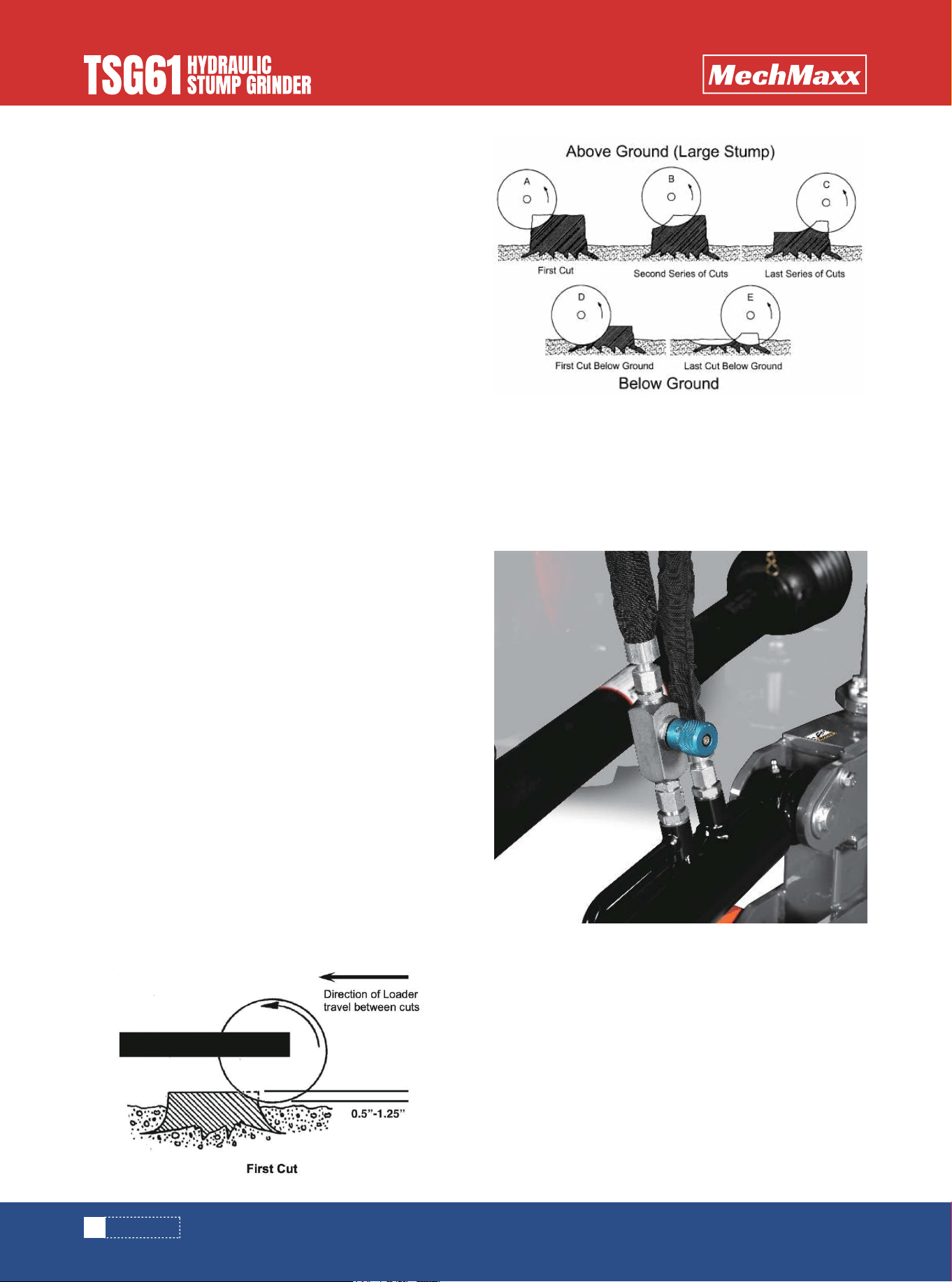
The cutting height should be 0.5"-1.25". we think the
customer cutting more than 1.25", that makes grinder
working slowly.
The grinder should work from right to left or left to right.
grinder parallel not vertical.
When the attachment has completed a pass, move it
rearward about 0.5“-1.25” and engage the control to cut
back across in the opposite direction. Never directly up to
down.
Operate the cutting wheel at 540 rpm (speed while under
no load).
The cutting wheel feed is controlled by the hydraulic cylin-
der and the pressure control valve.
The rate of cut will depend on the type of tree, condition
of the wood, and the condition of the carbide cutting
teeth.
Excessive feed rates will either stall the engine or slip the
clutch.
Too light a feed will produce sawdust.
Please adjust the two speed flow valves in the cylinders
by a suitable level depend on your tractor, ensure swing
cylinder make the arm by smooth/ and slow moving from
right to left. NEVER use high speed in cylinder /arm swing
moving.
TRACTOR MOUNTING
GRINDER

7
www.mechmaxx.com
MAINTENANCE
MAINTENANCE
Check hydraulic hoses and fittings daily for leaks.
Replace hose if worn or damaged. Investigate the
location of any oil leaks and repair. Lubricate all joints
with lithium grease.
Inspect the unit for any buildup of contamination (dirt,
stones, etc.).
Check cutting teeth every 2 hours of use. Keep cutting
teeth in good condition. Unit will cut faster and remaining
teeth will last longer if broken teeth are replaced.
Check that all fasteners (nuts, bolts, pins, keepers) are in
their right place and are tight. Inspect and replace any
worn, torn, or missing safety decals.
1.Support stump grinder to prevent falling.
2.Stop skid steer engine and remove key.
3.Inspect cutting teeth for damage. Rotated the tooth 3
times before replace it.
4.Replace individual teeth as needed.
5.Remove lock nut (1) and cutting tooth (2)
6.Rotated the tooth or install replacement tooth and lock
nut. Tighten locknut (1) to 95 lb./ft. (129 Nm) of torque.
Do not allow untrained or unqualified people to operate
this equipment.
Check the condition of the teeth base and/or teeth. Order
parts if the cutting edge or points are becoming worn and
replace as soon as possible.
Inspect the implement for any loose or worn parts that
may need to be replaced prior to the next season.
Visually inspect the teeth. Replace, if necessary.
Clean, sand & repaint any area that looks worn or
scratched to prevent further rusting. Use an equip-
ment-paint found at your local hardware store or building
center.
Replace any warning decals that have been lost or
damaged.
Store your implement in a shed or cover with a
water-proof tarp to protect it from the weather. Store in
an area not frequented by children.
BEFORE EVERY USE
CUTTING TEETH REMOVAL & REPLACEMENT
LUBRICATION
EVERY WEEK
AFTER EVERY SEASON
Gearbox
Type of Lubrication: SAE 90W Gear Lube
AS
REQUIRED
Check oil level in gearbox by removing the plug located on
the right hand side. Oil should be level with bottom of
plug hole. Add oil if necessary by removing top fill plug and
side plug. Add oil until it flows from side plug hole.
Do not overfill!
IMPORTANT: Implements should be level when checking
oil in gearbox!
8
www.mechmaxx.com
MAINTENANCE
Cutting edges can be very heavy and could cause Minor or
Serious Injury if mishandled. Always wear protective
gloves and footwear.
1.Weld-on cutting edge replacement is not a task for
most machinery operators and should be referred to a
welding shop that possesses the proper equipment,
knowledge, and experience.
2.Replacement cutting edges are available from your
dealer.
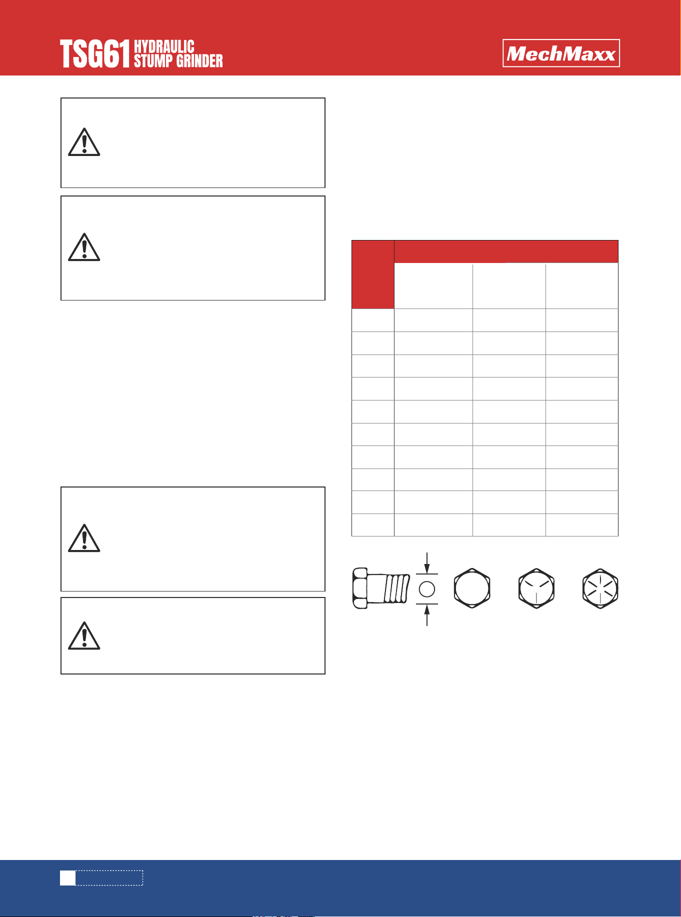
CHECKING BOLT TORQUE
The tables shown below give correct torque values for
various bolts and cap screws. Tighten all bolts to the
torques specified in chart unless otherwise noted. Check
tightness of bolts periodically, using bolt torque chart as
a guide. Replace hardware with the same strength bolt.
Torque figures indicated above are valid for non-greased
or non-oiled threads and heads unless otherwise speci-
fied. Therefore, do not grease or oil bolts or cap screws
unless otherwise specified in this manual. When using
locking elements, increase torque values by 5%.
* Torque value for bolts and cap screws is identified by
their head markings
HYDRAULIC SYSTEM
BOLT TORQUE
To avoid an accident that could result in
Death or Serious Injury, never find your-
self in a position where any body part is
located under an unsupported blade or
frame when servicing this attachment.
Hazardous dust can be generated if paint-
ed surfaces are heated or welded and
could result in death or Serious Injury.
Remove paint before welding and always
make repairs in a well-ventilated area and
wear an approved respirator.
A small stream of oil from a pinhole leak
could penetrate your skin if contacted. To
avoid an accident that could result in
Death or Serious Injury, never use your
hand or other body parts in an attempt to
locate a hydraulic leak.
Always release the hydraulic system pres-
sure from the hydraulic circuits prior to
removing the attachment or any hydraulic
system service work.
Bolt
Diameter
“A”
SAE 2
SAE-2
A
SAE-5 SAE-8
N.m lb-ft N.m lb-ft N.m lb-ft
SAE 5 SAE 8
Bolt Torque
1/4"
5/16"
3/8"
7/16"
1/2"
9/16"
5/8"
3/4"
7/8"
1"
8
13
27
41
61
95
128
225
230
345
6
10
20
30
45
60
95
165
170
225
12
25
45
72
110
155
215
390
570
850
9
19
33
53
80
115
160
290
420
630
17
36
63
100
155
200
305
540
880
1320
12
27
45
75
115
165
220
400
650
970
ENGLISH TORQUE SPECIFICATIONS
9
www.mechmaxx.com
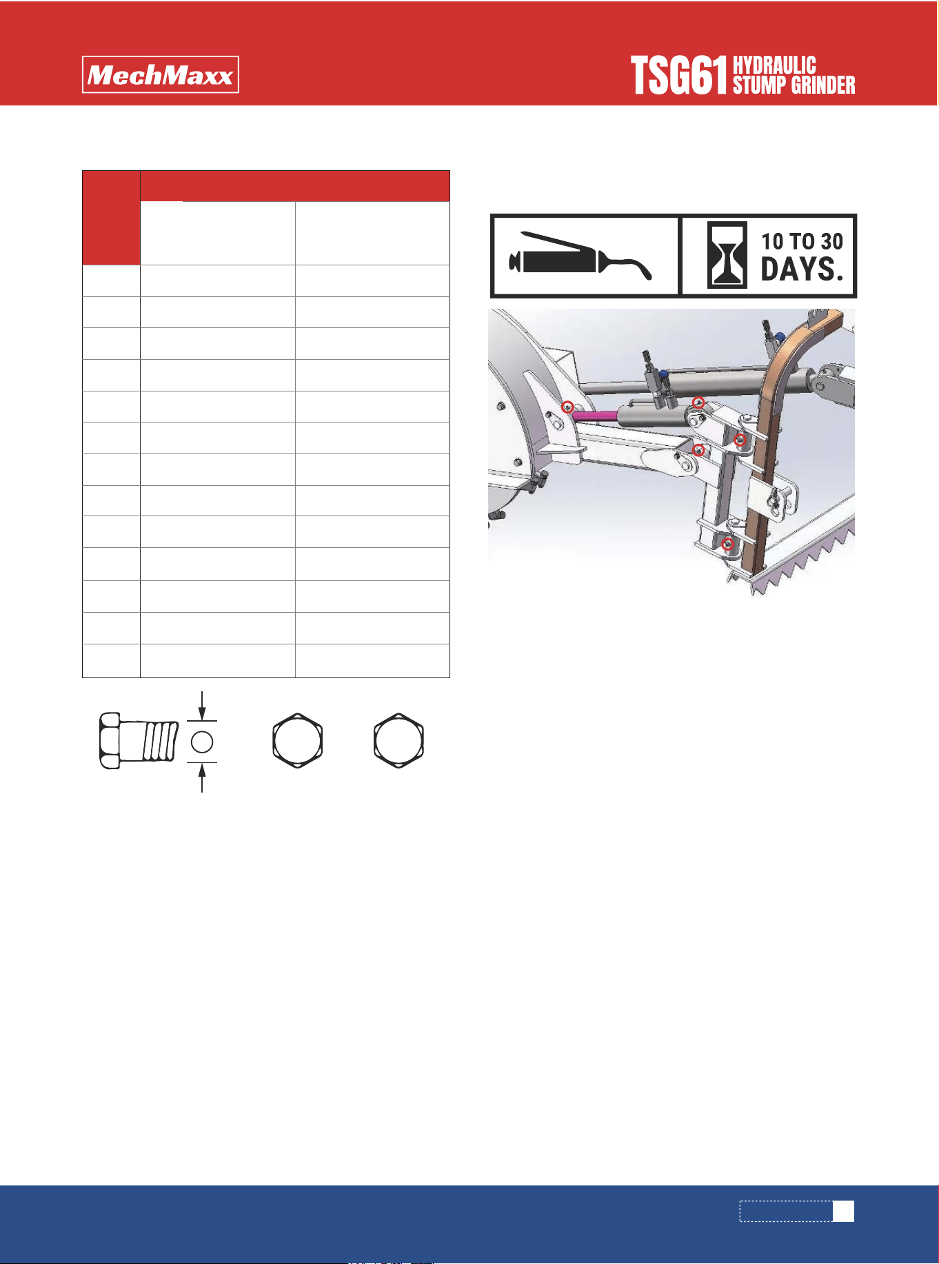
MAINTENANCE
TSG61 grease fitting: Lubricate approximately once every
10 to 30 days.
Bolt
Diameter
“A”
8.8
N.m lb-ft N.m lb-ft
10.9
Bolt Torque
M3
M4
M5
M6
M8
M10
M12
M14
M16
M20
M24
M30
M36
0.5
3
6
10
25
50
90
140
225
435
750
1495
2600
0.4
2.2
4
7
18
37
66
103
166
321
553
1103
1917
1.8
4.5
9
15
35
70
125
200
310
610
1050
2100
3675
1.3
3.3
7
11
26
52
92
148
229
450
744
1550
2710
METRIC TORQUE SPECIFICATIONS LUBRICATION
A
8.8 10.9
10
www.mechmaxx.com
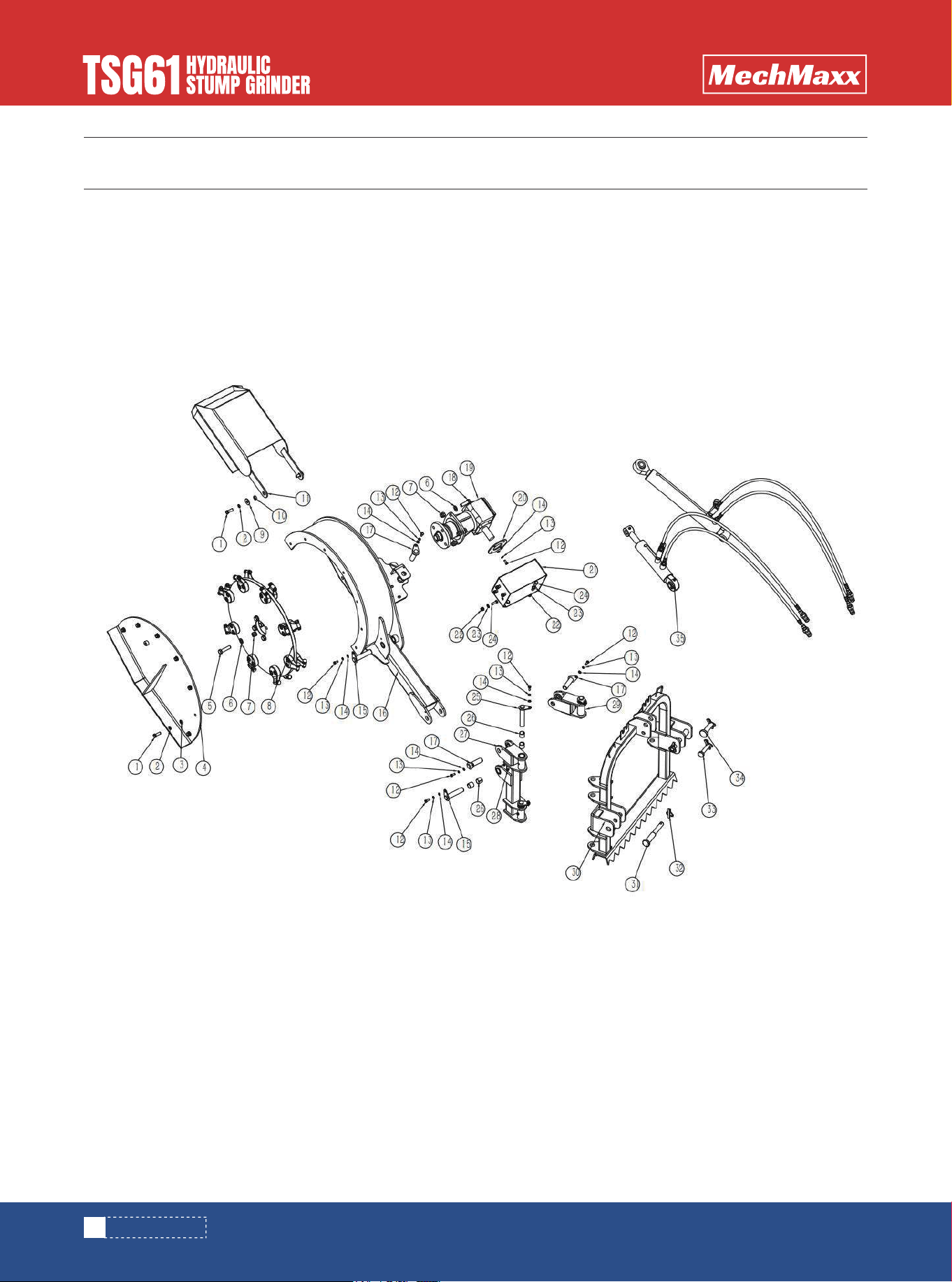
PARTS DIAGRAM
PARTS DIAGRAM

11
www.mechmaxx.com
PARTS LIST
PARTS LIST
REF DESCRIPTION QTY
1
2
3
4
5
6
7
8
9
10
11
12
13
14
15
16
17
18
19
20
21
22
23
24
25
26
27
28
29
Bolt M12X35
Spring Washer 12
Washer 12
Outer Plate Weldment
Bolt M16*65
Washer 16
Lock Nut M16
Cutting WheelAssembly
Big Washer 12
Guard Spacer
Guard Weldment
Bolt M8X20
Spring Washer 8
Washer 8
Cylinder Pin 1
Frame Weldment
Cylinder Pin 2
Bolt M16X50
Gearbox Assembly
Gearbox Protection Plate
Gearbox Protection Cover
Lock Nut M10
Washer 10
Bolt M10X30
Rotary Linkage Weldment
Bearing 28X25X25
Rotary Weldment
Grease Nipple M8
Rotary Weldment 2
9
9
7
1
4
8
8
1
2
2
1
12
12
12
2
1
3
4
1
1
1
8
8
8
3
8
1
4
1
1
2
4
1
1
1
REF DESCRIPTION QTY
30
31
32
33
34
35
Supporting Weldment
Lower Pin
Lock Pin 10*45
Upper Pin 01
Upper Pin 02
Hydraulic Components
12
www.mechmaxx.com
PARTS DIAGRAM
PARTS DIAGRAM
PARTS LIST
1
4
1
1
1
4
4
4
1
1
1
1
REF DESCRIPTION QTY
1
2
3
4
5
6
7
8
9
10
11
12
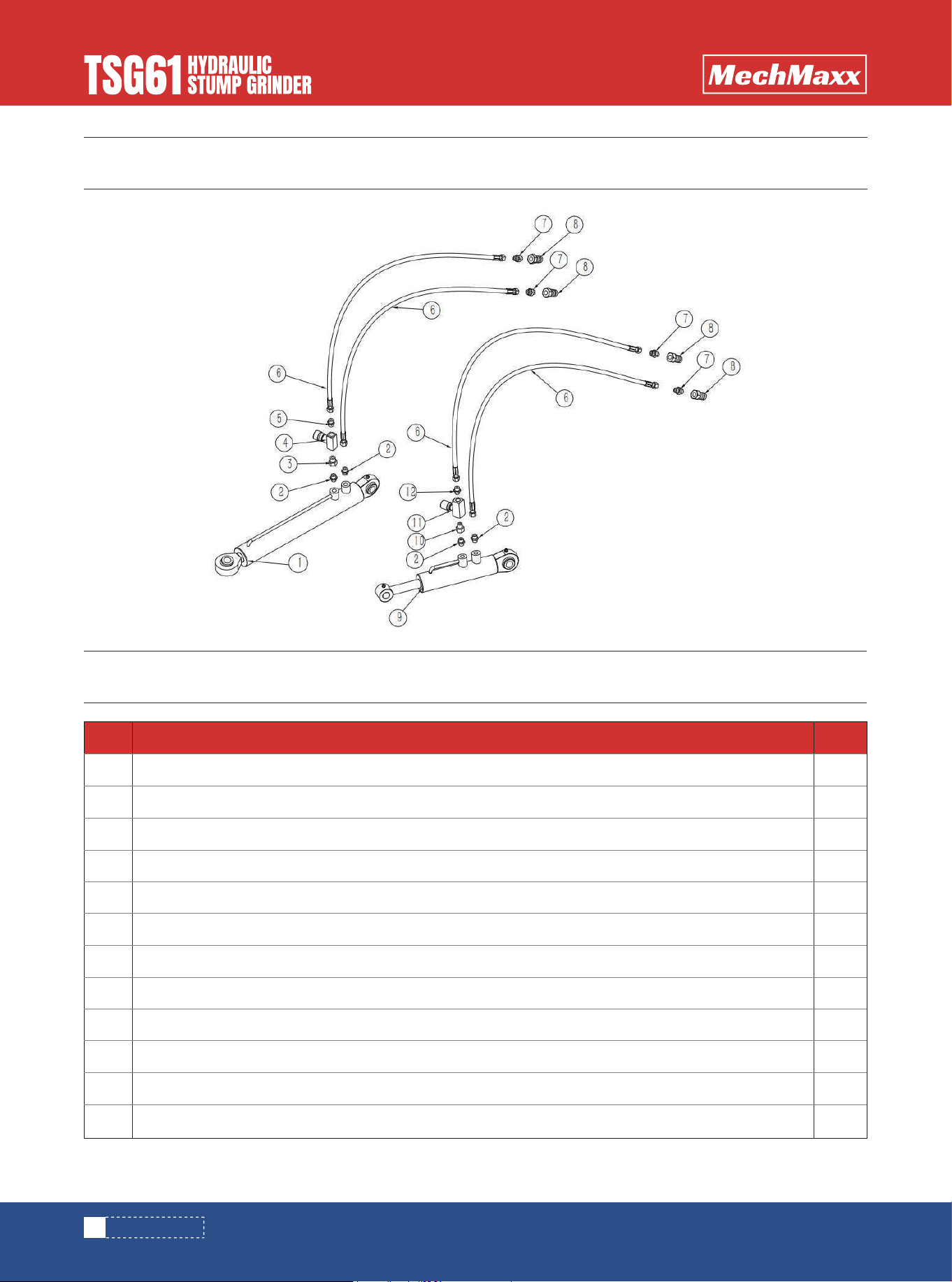
Swing Cylinder
End Straight Joint M16x1.5-M16x1.5
End Straight Joint M16x1.5-G3/8
Control Valve
End Straight Jointm16x1.5-G3/8
Oil Hose
End Straight Joint M16*1.5-G1/2"
Quick Change Connector G1/2
Lifting Cylinder
End Straight Joint M16x1.5-G1/4
One-Way Flow Control Valve
End Straight Joint M16x1.5-G1/4
13
www.mechmaxx.com
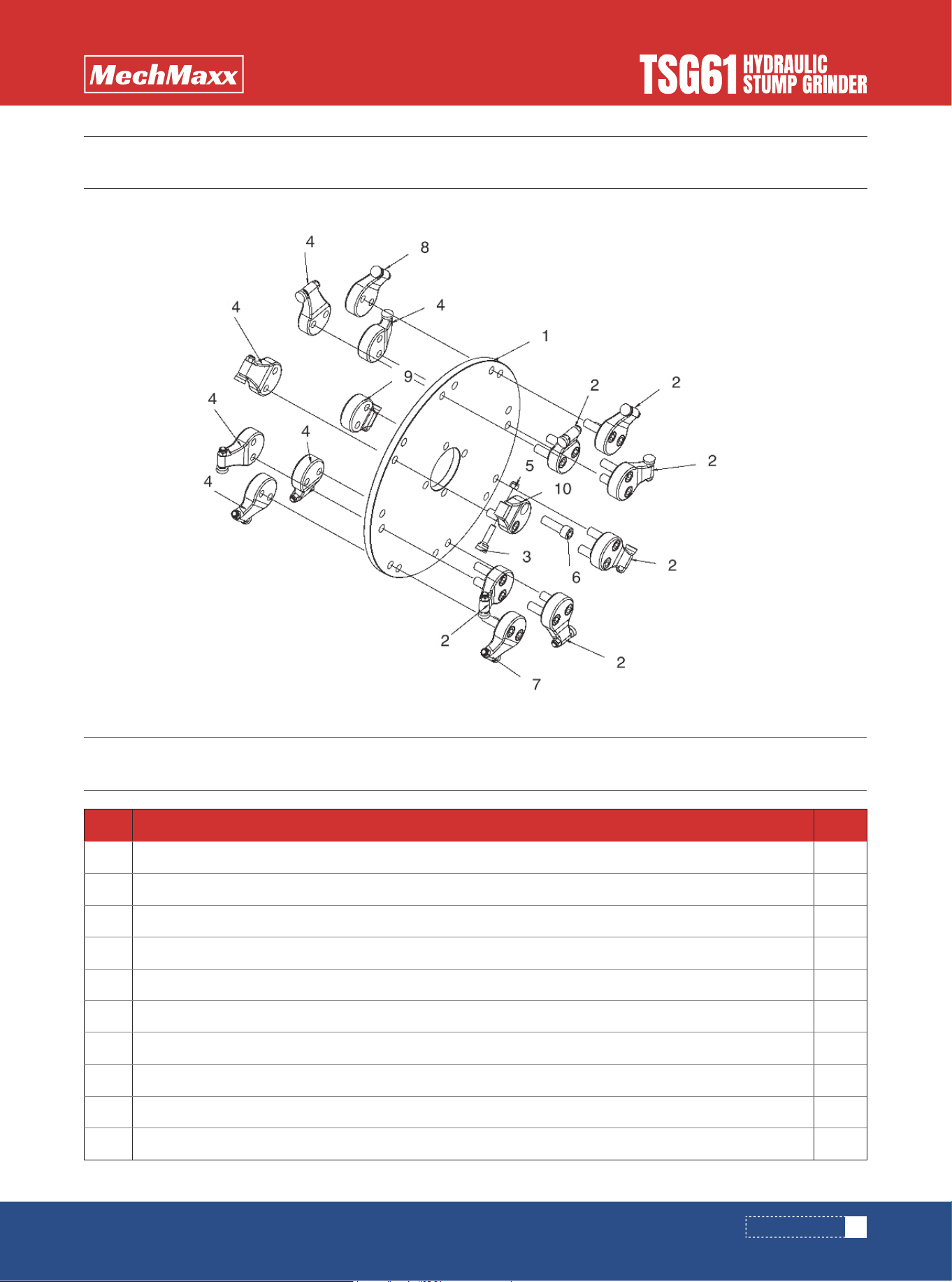
PARTS DIAGRAM
PARTS DIAGRAM
PARTS LIST
1
6
16
6
16
16
1
1
1
1
REF DESCRIPTION QTY
1
2
3
4
5
6
7
8
9
10
Cutting wheel
Teeth base900-2
Teeth 900
Teeth base900-3
Nylon Insert Lock Nuts
HEX SOCKET HEAD BOLT
Teeth base900-4
Teeth base900-5
Teeth base900-6
Teeth base900-1