
Operator’s Manual
www.mechmaxx.com
WARRANTY
WARRANTY


MAX performance,MAX Value,MAX Support that’s
Stump Grinder
Enhanced design features come standard
Engineered for the best user experience
Quality metal parts are used instead of plastic
A robust warranty supports all products
OVERALL DIMENSIONS
3-POINT HITCH DIMENSIONS
Budget-friendly prices make it practical
TABLE OF CONTENTS
TABLE OF CONTENTS
SPECIFICATIONS
SAFETY SIGNS
SAFETY
1
2
2
3
TRIMMING THE PTO SHAFT
DETERMINE DRIVESHAFT LENGTH
12
12
PREPARATION FOR USE
ATTACH STUMP GRINDER TO TRACTOR
16
16
REPLACING TEETH
GREASING
22
22
FIRST TIME USER TIPS
17
FIELD OPERATION
18
GENERAL SAFETY RULES
PERSONAL SAFETY
4
4
TOP LINK BRACKET
DEFLECTOR
9
9
CHAINSAW HOLDER
MANUAL TUBE
9
10
3
4
6
7
8
9
UNPACKING THE CONTAINER
CONTENTS SUPPLIED
TO-SCALE HARDWARE
ASSEMBLY
11
12
KNOW YOUR MACHINE
SET-UP PROCEDURES
13
PTO SHAFT CLUTCH RUN-IN
14
FLYWHEEL TOOTH TORQUING
15
OPERATION
16
STARTUP
19
20
STUMP GRINDING PROCEDURE
MACHINE USE AND CARE
22
MAINTENANCE
23
TROUBLESHOOTING
24
STORAGE
25
26
Your new PTO Stump Grinder offers quality construction,
and is easy and safe to operate. With proper use and
care, it is designed to give you many years of depend-
able service.
Prepare to experience the durability to take on any job
with the ease, portability, and convenience of your new
PTO Stump Grinder !
1
www.mechmaxx.com
TABLE OF CONTENTS
PARTS DIAGRAM
PARTS LIST
SPECIFICATIONS
OVERALL DIMENSIONS
2
www.mechmaxx.com
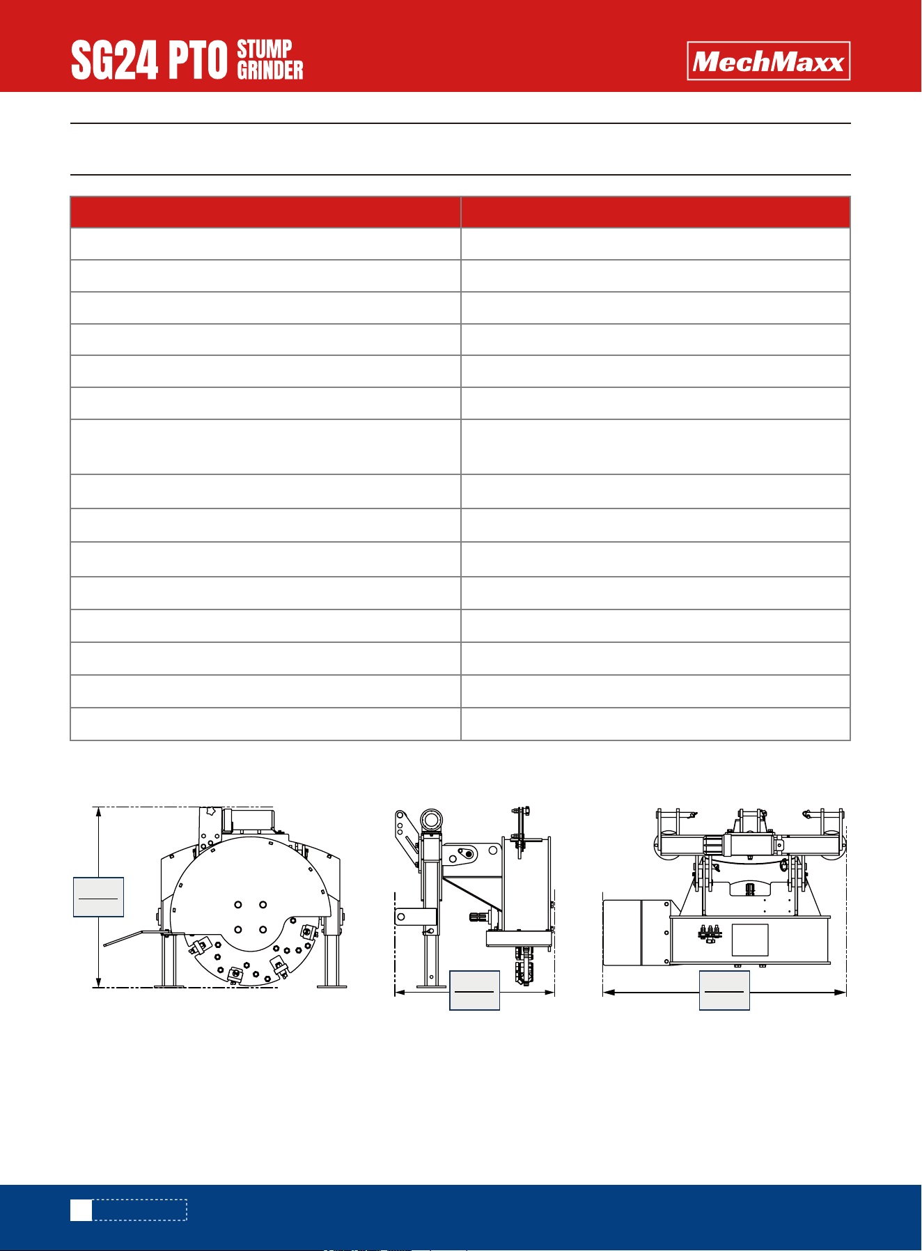
SPECIFICATIONS
Flywheel Thickness
Model
3/4 in
Flywheel Diameter 24 in
SG24
Carbid Tip 34 pcs
Carbid Tip Material YG11C
Tip Holder Material
42CrMo
PTO Shaft (Included Shipping)
PTO HP Required
1-3/8” 6 Spline Tractor and Implement Ends PTO
Driveline Shaft with Slip Clutch
15–45 HP
Friction Torque Limiter (Slip Clutch) Included
Mounting 3 point hitch Cat. 1 (Quick attach compatible)
PTO Input
Max. Torque
540 RPM
1200 N·m
PTO Shaft Weight 44 lbs
Dimensions 29 x 37x 38 in
Packing Iron frame + Carton
Weight (N.W/G.W.) 450/563 lbs
802mm
31.5”
705mm
27.7”
1081mm
42.5”

3
www.mechmaxx.com
SAFETY SIGNS
3-POINT HITCH DIMENSIONS
The rating plate on your machine may show symbols. These represent important information about the product or instruc-
tions on its use.
314mm
12.3”
795mm
31.2”
655mm
25.7”
65mm
2.55”
316mm
12.4”
453mm
17.8”
406mm
15.9”
377mm
14.8”
349mm
13.7”
SAFETY SIGNS
4
www.mechmaxx.com
GENERAL SAFETY RULES
SAFETY
SAFETY
▪ All Federal and State laws and any regulation having
jurisdiction covering the safety requirements for use of
the machine take precedence over the statements in
this manual. Users of this machine must adhere to such
regulations.
▪ Only people that have read and understood these
instructions are permitted to use the stump grinder.
▪ Inspect the stump grinder and tractor at the beginning
of every working day and repair any defects.
▪ Stop the engine and make sure that the machine will
not start accidentally while repairing defects or
performing maintenance.
▪ Do not disable or remove the stump grinder's safety
devices.
▪ Always locate and mark buried wires, cables, and
pipelines prior to grinding.
▪ Stay alert, watch what you are doing and use common
sense when operating machinery. Do not use a machine
when you are tired or under the influence of drugs,
alcohol, or medication. A moment of inattention while
operating machinery may result in serious personal
injury.
▪ Dress properly. Do not wear loose clothing, dangling
objects, or jewelry. Keep your hair, clothing, and gloves
away from moving parts. Loose clothes, jewelry, or long
hair can be caught in moving parts. Air vents often
cover moving parts and should be avoided.
▪ Use safety apparel and equipment. Use safety goggles
or safety glasses with side shields which comply with
current national standards, or when needed, a face
shield. Use a dust mask in dusty work conditions. This
applies to all persons in the work area. Also use
nonskid safety shoes, hardhat, gloves, dust collection
systems, and hearing protection when appropriate.
▪ Do not overreach. Keep proper footing and balance at
all times.
▪ Remove adjusting keys or wrenches before connecting
to the power supply or turning on the machine. A
wrench or key that is left attached to a rotating part of
the machine may result in personal injury.
▪ Never conduct any maintenance or make any other
adjustments while the tractor engine is running.
Always shut the tractor engine off, remove the ignition
key, and keep the engine off before carrying out any of
the following procedures. Consult your tractor's opera-
tor manual for safe shutdown procedures to prevent
accidental ignition.
▪ Never allow passengers to ride on the stump grinder.
Read this manual and labels affixed to the machine to
understand its limitations and potential hazards.
Be thoroughly familiar with the controls and their proper
operation.
If the unit is to be used by someone other than original
purchaser or loaned, rented, or sold, always provide this
manual and any needed safety training before operation.
The user can prevent and is responsible for accidents or
injuries that may occur to themselves, other people, and
property.
Do not permit children to operate this machine at any
time.
Keep children, pets, and other people not using the unit
away from the work area. Be alert and shut off unit if
anyone enters work area. Keep children under the watch-
ful care of a responsible adult.
Identify hazards and take preventive steps to avoid
accidents and minimize risk. Possible hazards include,
but are not limited to, moving parts, thrown objects,
weight of the machine and components, and the operat-
ing environment.
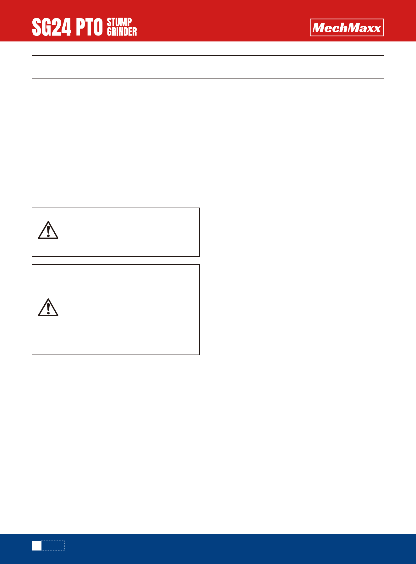
Read and understand all instructions.
Failure to follow all instructions listed
below may result in electric shock,fire,
and/or serious injury.
The warnings, cautions, and instructions
discussed in this instruction manual
cannot cover all possible conditions or
situations that could occur. It must be
understood by the operator that common
sense and caution are factors which
cannot be built into this product but must
be supplied by the operator.
PERSONAL SAFETY

5
www.mechmaxx.com
SAFETY
Thoroughly inspect the area in which you are working,
keeping it clean and free of debris to prevent tripping.
Operate on a flat level ground.
Never place any part of your body where it would be in
danger if movement should occur during assembly, instal-
lation, operation maintenance, repair, or moving.
Keep all bystanders and pets at least 75 feet away. If you
are approached, stop the unit immediately.
6
www.mechmaxx.com
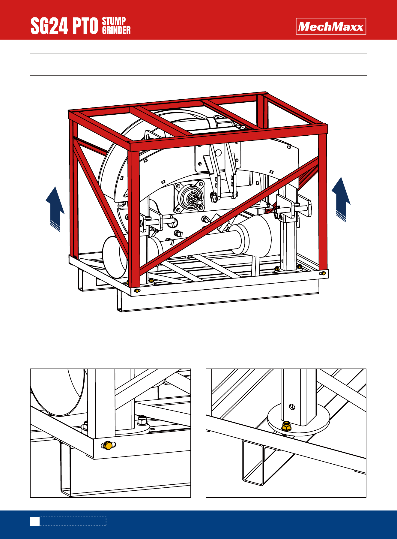
UNPACKING THE CONTAINER
UNPACKING THE CONTAINER
Unfasten the M8 X 20 mm hex bolts from the four (4)
bottom corners of the crate and remove the top frame.
TOP FRAME
Unfasten the two (2) M10 × 25 mm hex bolts securing
both support legs to the bottom crate frame.
SUPPORT LEG
7
www.mechmaxx.com
CONTENTS SUPPLIED
CONTENTS SUPPLIED
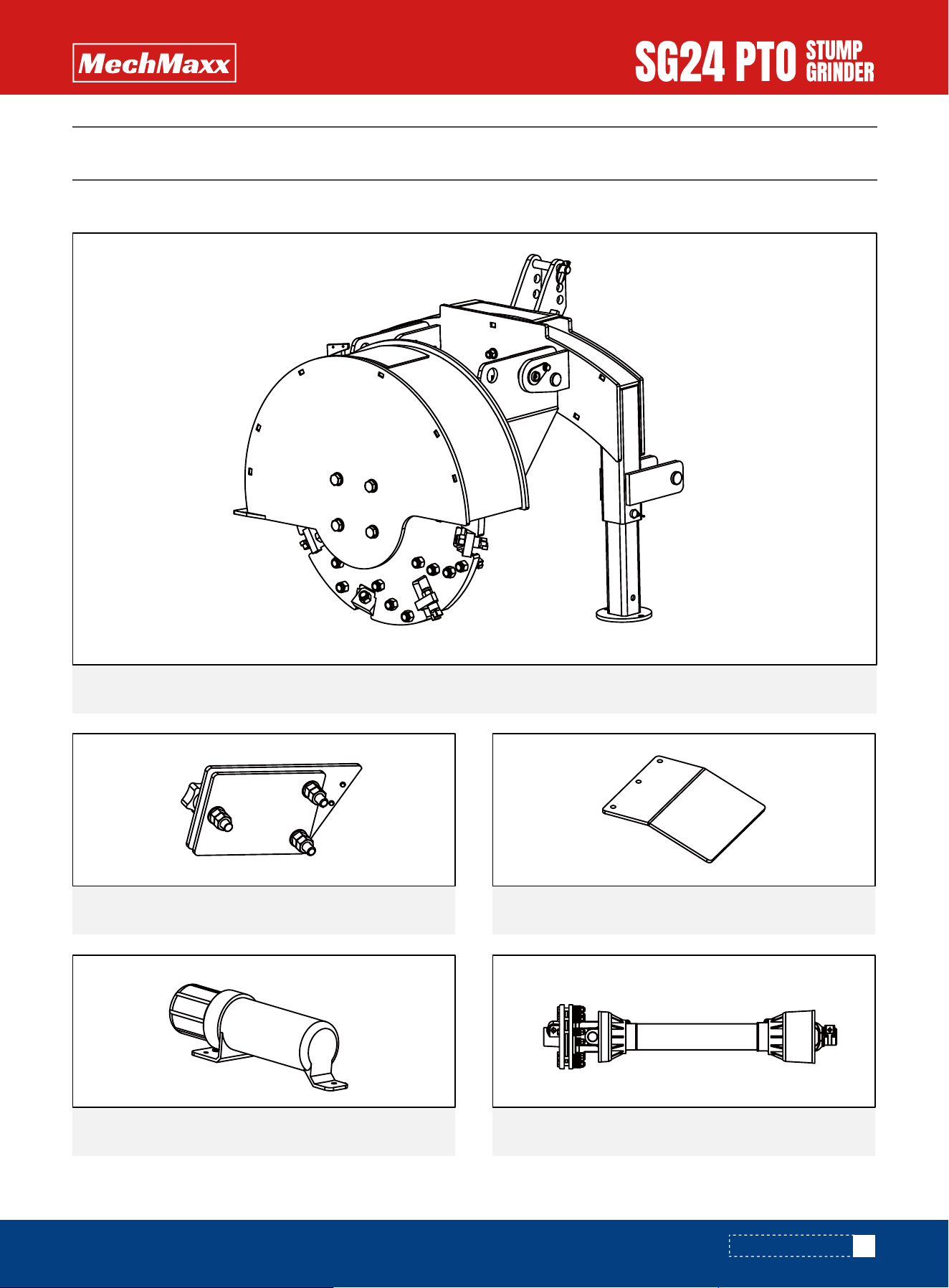
Your PTO Stump Grinder comes partially assembled and contains the following:
Verify all component and hardware quantities are correct prior to assembling the stump grinder.
Chainsaw Holder Assembly1x
1x
1x
1x
1x
Deflector Plate
SG24 PTO STUMP GRINDER
Manual Tube PTO Shaft
8
www.mechmaxx.com
TO-SCALE HARDWARE
TO-SCALE HARDWARE
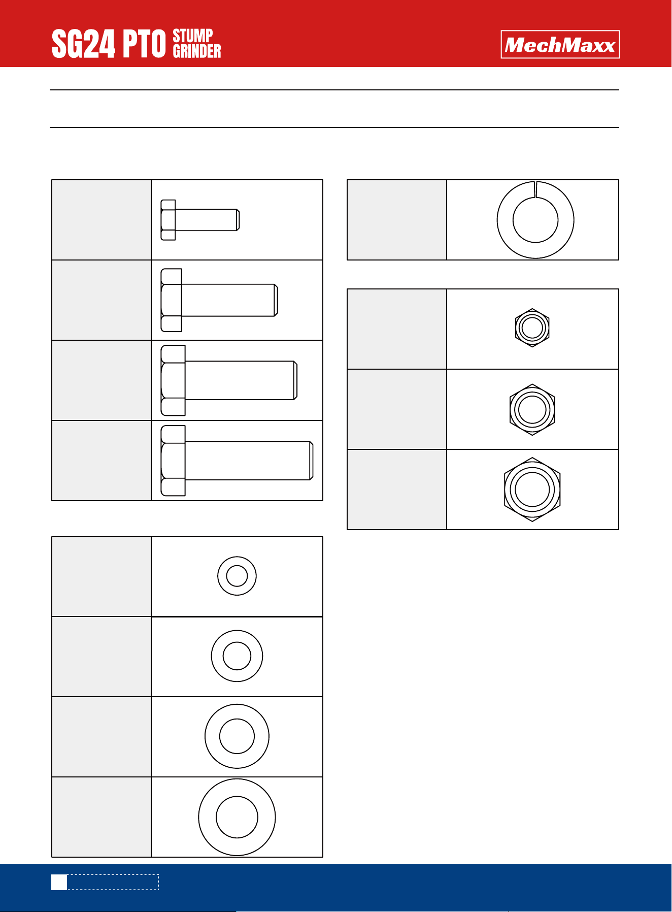
Hardware graphics are printed at 1:1 scale for ease of identification. Simply place the hardware over the image in the
tables to verify it is the correct size.
M8 X 30mm
Hex bolt
3X
M6 X 20mm
Hex bolt
2X
M10 X 35mm
Hex bolt
2X
M12 X 40mm
Hex bolt
4X
nut M8
Hex lock
3X
10
Flat washer
2X
6
Flat washer
6X
8
Flat washer
6X
12
Flat washer
4X
12
Spring washer
4X
2X
nut M10
Hex lock
2X
nut M6
Hex lock
9
www.mechmaxx.com
ASSEMBLY
ASSEMBLY
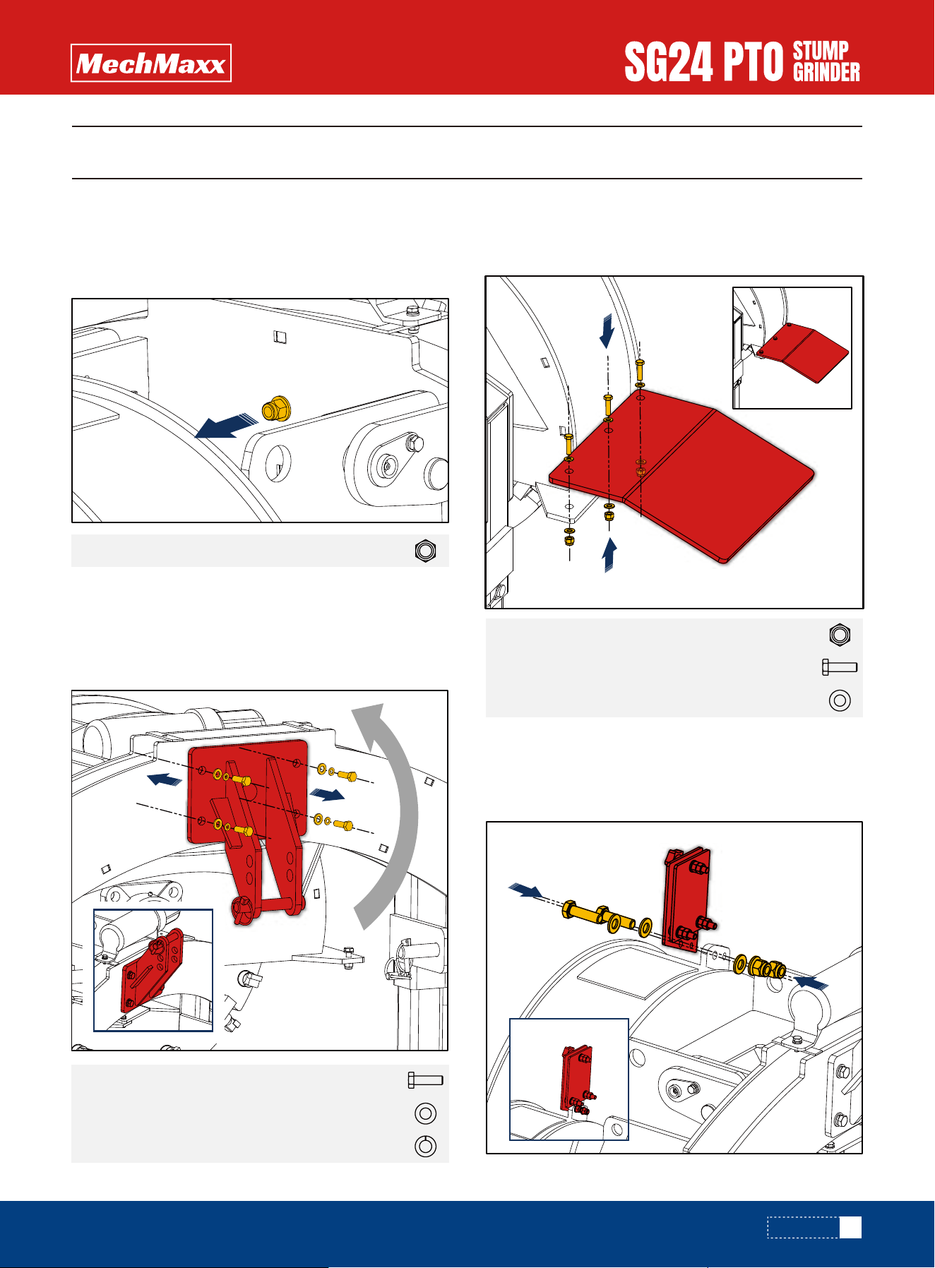
Loosen the nut on the front side of the back frame just
enough so the top link bracket can be rotated 180° for
the next assembly step.
Orient the top link bracket so that it is rotated 180° from
how it was shipped in the previous step.The hitch pin
must be on top. Secure it to the back frame using four (4)
M12 X 40 mm hexbolts, M12 flat washers,and Spring
washer 12.
TOP LINK BRACKET
Using the hardware listed below, assemble the deflector
to the flywheel housing as shown.
DEFLECTOR
Using the hardware listed below, assemble the chainsaw
holder to the flywheel housing as shown.
CHAINSAW HOLDER
Hex lock nut M12
Hex bolt M12 X 40mm
Flat washer 12
Spring washer 12
4X
4X
4X
Hex lock nut M83X
Hex bolt M8 X 30mm
Flat washer 8
3X
6X
ASSEMBLY
10
www.mechmaxx.com
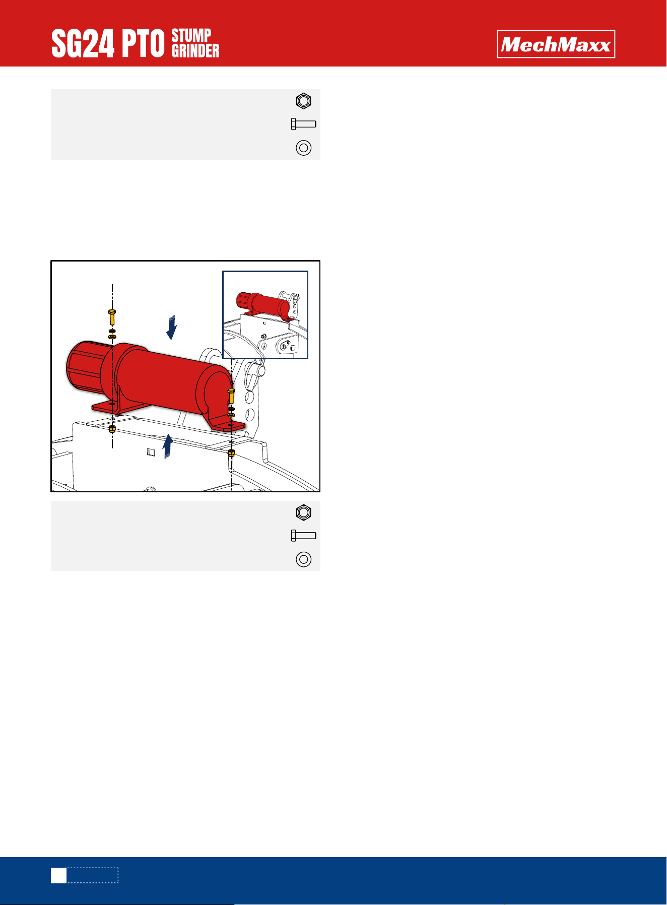
Using the hardware listed below, assemble the manual
tube to the back frame as shown.Remove the cap from
the manual tube to gain access to the centre mounting
hole.
MANUAL TUBE
Hex lock nut M102X
Hex bolt M10 X 35mm
Flat washer 10
2X
2X
Hex lock nut M62X
Hex bolt M6 X 20mm
Flat washer 6
2X
2X
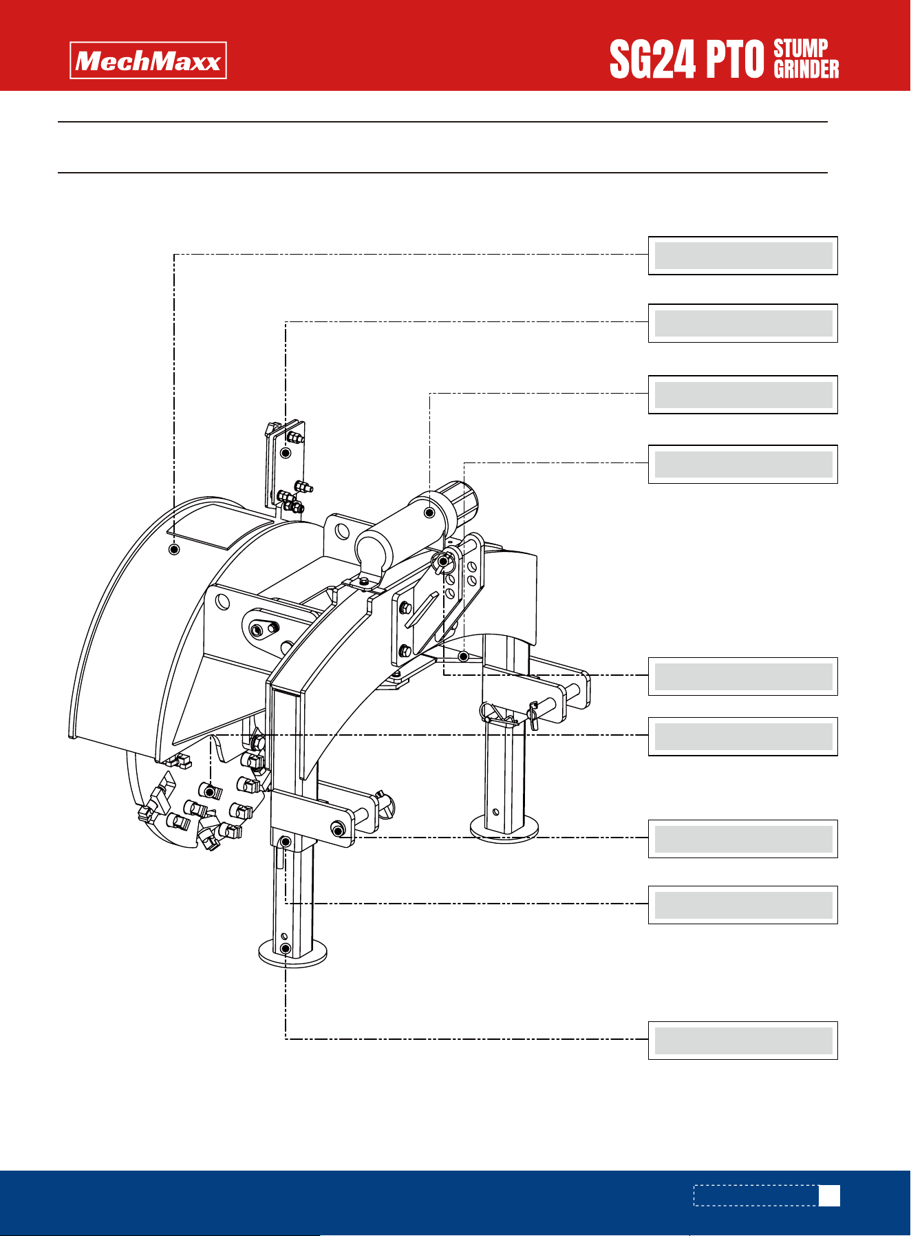
KNOW YOUR MACHINE
Cutting Wheel Shield
KNOW YOUR MACHINE
11
www.mechmaxx.com
Chainsaw Holder
Manual Tube
Deflector
3-Point Top Link Pin
TEETH
Parking Stands
Locking Pins
3-Point Top Link Pin
12
www.mechmaxx.com
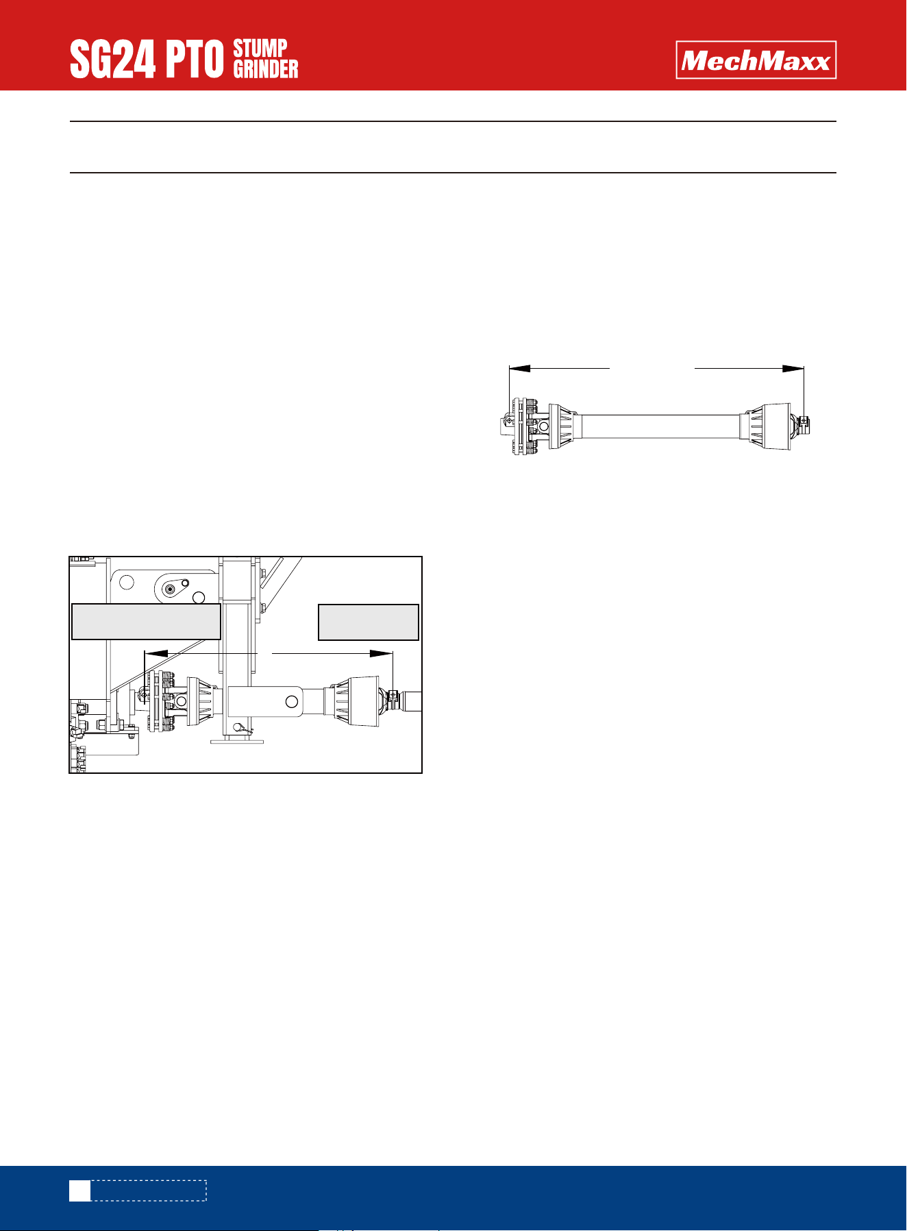
SET-UP PROCEDURES
SET-UP PROCEDURES
The stump grinder is shipped with a slip clutch PTO shaft
that can be fitted to most Category 1 tractors. The PTO
shaft may need to be trimmed depending on your tractor
and configuration. Follow the steps below to ensure the
PTO shaft is correctly fitted to your tractor.
Verify the distance between the locking pins on the PTO
shaft while in the compressed state(Dim B) as shown
in the image below. It should measure 34" (862.5 mm).
If Dim A is at least 1" (25 mm) longer than Dim B, the
PTO shaft does not require trimming. It is recommend-
ed the shaft not be used if there is less than 6" (150
mm) of overlap between the two halves of the PTO
shaft when the equipment is in the operating position.
If Dim B is longer than Dim A, the PTO shaft will require
trimming. Use this equation to calculate the correct
amount to trim:
Note: the slip clutch end of the PTO shaft mounts to the
stump grinder.
After trimming both halves of the PTO shaft, use a file to
remove any burrs or sharp edges and slide the halves back
together, ensuring they telescope in-and-out freely. The
PTO shaft is now ready to connect the stump grinder to the
tractor for operation.
(B- A) +1 inch =C (Amount to Trim)
Once C has been calculated, trim that amount from BOTH
halves of the PTO shaft safety cover first, then trim the
same amount from both shafts. This will ensure the
safety cover on each end remains a few inches back from
the ends of the shafts, otherwise PTO shaft reassembly
could be difficult.
▪ Attach the stump grinder to the tractor's 3-point
hitch system. Do not install the PTO shaft.
▪ Raise the stump grinder so that the shaft on the
tractor is in line with the shaft on the stump grinder.
▪ Measure the distance between the locking grooves
on the splined shafts of the tractor and stump grind-
er (Dim A) as shown below:
TRIMMING THE PTO SHAFT
Determine Driveshaft Length
B
A
Stump Grinder
Tractor
13
www.mechmaxx.com
7-5/8" (200 mm)
15-20hp 1.26" (31.9 mm)
1.25" (31.7 mm)
1.24" (31.4 mm)
1.22" (31.1 mm)
1.20" (30.5 mm)
25hp
30hp
35hp
45hp
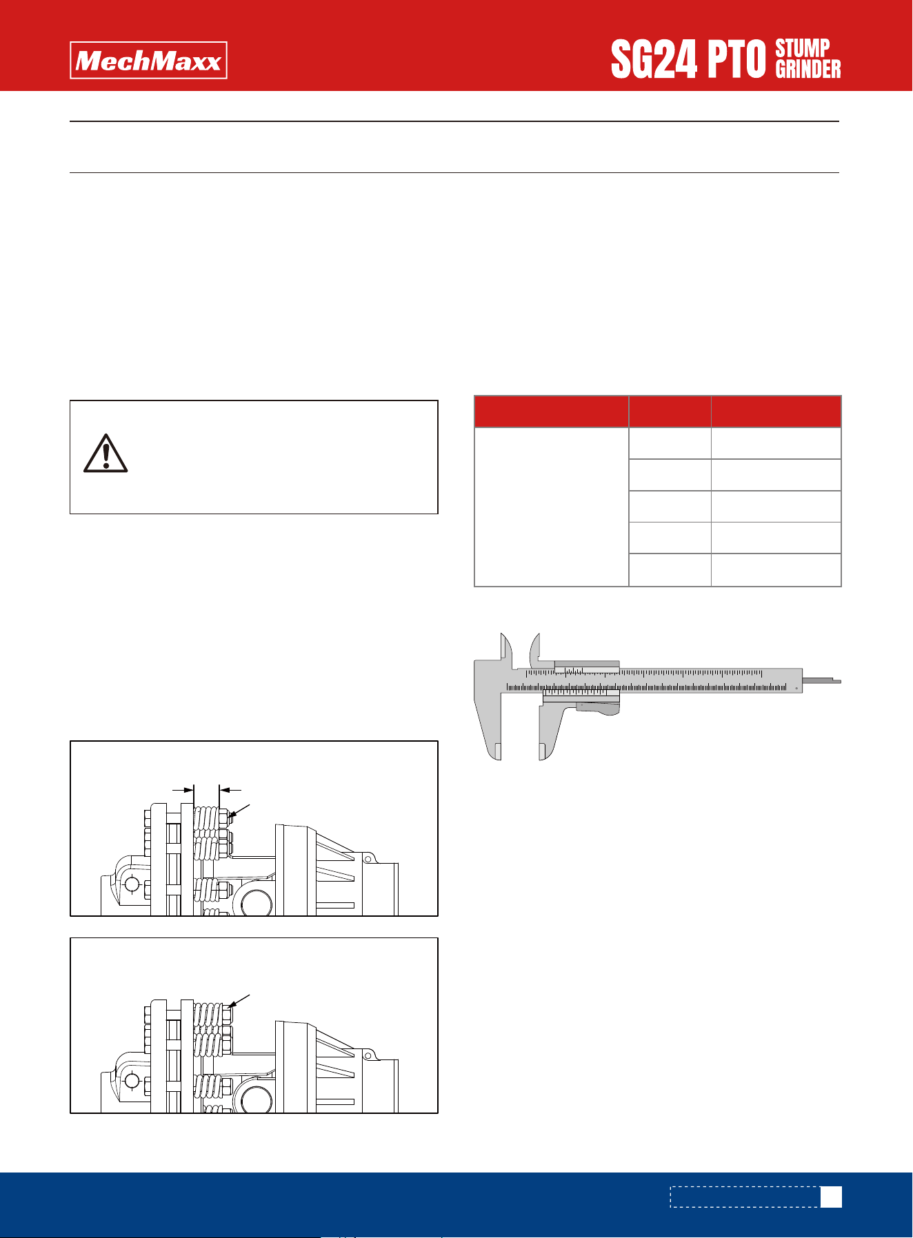
Clutch Flange Dia PTO hp Spring Height
The stump grinder is shipped with a slip clutch PTO shaft.
Follow the steps below before usingyour stump grinder to
ensure the PTO shaft clutch plates are set properly.
**This procedure should be performed periodically during
ownership as the clutch plates can stick together, partic-
ularly after long periods of inactivity. This can prevent the
plates from slipping during operation as designed, result-
ing in high loads and possible damage to the steel shaft,
which is not covered under warranty.**
▪ Connect the PTO shaft to the stump grinder and tractor
with the clutch end of the PTO shaft mounted to the
stump grinder. Insert the locking pin on the clutch yoke
and tighten the nut using a wrench/socket.
▪ Using a coloured pencil or marker, scribe a line across
the exposed edges of the clutch plates.
▪ Using a wrench/socket, loosen all 8 spring tension
nuts uniformly until the ends of the nuts are flush with
the ends of the bolts .
▪ Start the tractor and engage the PTO for 2-3 seconds
to permit slippage of clutch surfaces. Disengage the
PTO then re-engage a second time for 2-3 seconds.
Disengage the PTO again, shut off the tractor, and
remove the key. Wait for all components to stop rotat-
ing before removing the PTO shaft from tractor.
▪ Inspect the clutch and ensure that the scribed mark-
ings made across the clutch plates have changed
position. Slippage has not occurred if the two marks on
the clutch plates are still aligned. A clutch that has not
slipped must be disassembled to separate the clutch
plates.
▪ Tighten all 8 nuts until the proper spring height dimen-
sion values are achieved per the "PTo Shaft Clutch
Spring Height vs. Horsepower" table for your PTO
output horsepower. It is recommended that a calliper
(either digital, dial, or vernier-similar to the one shown
below) be used to accurately verify the spring height
measurements. After setting all 8 spring heights, the
clutch is now ready for use.
▪ The clutch should be checked during the first hour of
use and periodically each week thereafter. Excessive
clutch plate slippage, burning odour, or visible smoking
should not be observed during use.
PTO SHAFT CLUTCH RUN-IN
PTO SHAFT CLUTCH RUN-IN
Entanglement in a rotating driveshaft can
cause serious injury or death.Disconnect
and lockout power source before adjusting
or servicing.
Spring Tension Nut
PTO Shaft Clutch Spring Height vs. Horsepower
All ratings are at 540 rpm PTO speed
Typical vernier calliper
Spring Height
Nuts flush with bolt ends
0
1234 5678 9 10 11 12 13 14 15 16 17
cm
0
0 4
1/128
0 1
2
3
4
5
678
09
1/20
1
2
3
4
5
6
8
inch
14
www.mechmaxx.com
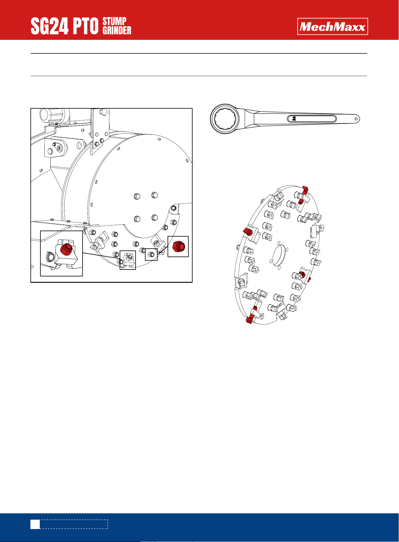
TORQUE ADAPTER
FLYWHEEL TOOTH TORQUING
FLYWHEEL TOOTH TORQUING
Prior to each operation, be sure to tighten all 34 teeth
using a ring spanner with a 24 mm socket.
Slide the ring spanner over the nut and torque the nut by
rotating it clockwise. Repeat the process for all four (4)
of the outward-pointing teeth.

15
www.mechmaxx.com
PRE-START CHECKLIST
OPERATION
OPERATION
Check the three lynch pins on the hitch to verify
they are securely fastened.
Verify the pins on each end of the drive shaft are
secured.
Verify the safety chains on the drive shaft are
securely attached to the cover.
Grease pivot pins
Check these items:
Frequency
Each operation.
Each operation.
Each operation.
Each operation.
Every 4 hours.
Verify the cutting tips on the cutting wheel are tight.
16
www.mechmaxx.com
STARTUP
STARTUP
Although the stump grinder has been carefully inspected
and checked prior to shipment from manufacturer, it is
recommended that the unit be thoroughly inspected.
Check all bolts for tightness and remove all shipping tags,
bags, skids, and blocking. Remove any masking materials
affixed during painting. Inspect the tractor and any
accessory equipment to verify that nameplates and all
safety warning, caution signs and decals provided with
the equipment are in place and clearly visible. Verify the
three lynch pins are securely fastened. Visually inspect
the unit before each start up. Check for loose or missing
parts and any damage that may have occurred during
moving or shipping.
Review all tractor pre-start instructions, and ensure that
all recommended steps and procedures have been
followed. Never bar over the rotor, This could cause
damage and result in personal injury or equipment
damage.Note: Always keep the weight of the machine in
mind. Never position body in line of impact.
To prevent injury or machine damage put transmission in
"Park" and check the full range of hitch for interference,
binding or PTO separation.Never position yourself
between tractor and stump grinder.Only experienced and
properly trained operator's should operate the tractor and
stump grinder.
▪ Check for loose teeth or any other loose parts.
▪ Verify there is sufficient visibility and maneuverability
to move up to stump grinder.
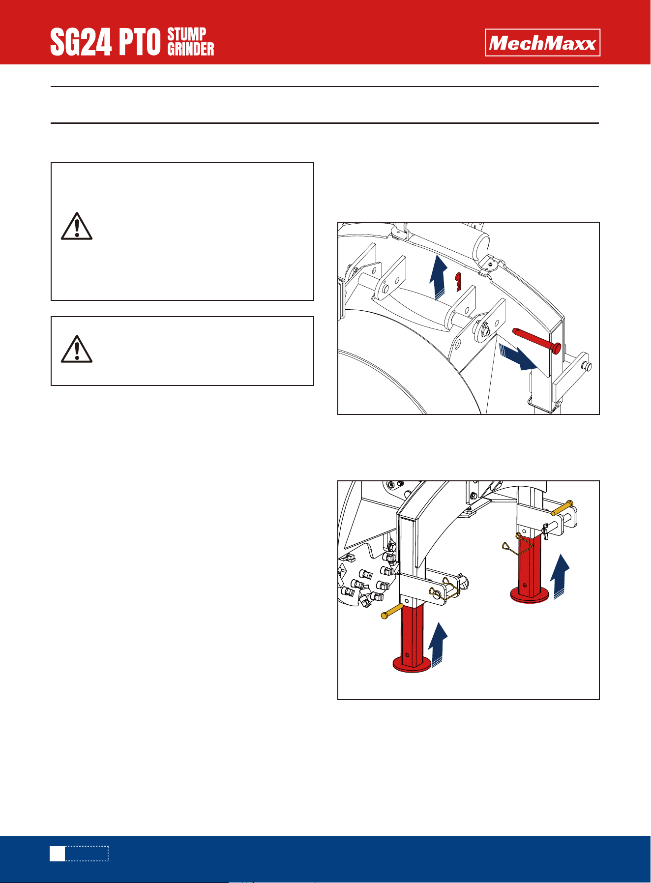
▪ Remove the stabilizer pin prior to operation as shown
below:
▪ Remove the leg locking pins, slide the legs up inside the
tubes, and reinstall the locking pins to secure them in
place.
PREPARATION FOR USE
ATTACH STUMP GRINDER TO TRACTOR
The warnings, cautions, and instructions
discussed in this instruction manual
cannot cover all possible conditions or
situations that could occur. It must be
understood by the operator that common
sense and caution are factors which
cannot be built into this product but must
be supplied by the operator.
Wear an approved dust mask or respira-
tor.Follow local, state and federal regula-
tions.
17
www.mechmaxx.com
STARTUP
Before you begin, make sure the tractor is turned off and
the PTO drive is disengaged.
Stand to the side of the stump grinder and observe the
center point on the bottom of the cutting wheel. Now sit
on the tractor seat and observe the center point again.
This point will appear different depending on where you
are positioned. This can be very deceiving! Familiarize
yourself with the view of the stump grinder from the
tractor seat.
Test all operating functions in an open area with the
tractor at idle speed to get a feel for the controls. Take
your time.
Start with a small stump. Make the first pass then disen-
gage the PTO drive and get off the tractor to see how
much you have removed.
Get off the tractor after each pass to check the progress.
The cutting wheel is shielded from view when sitting on
the tractor seat so it is difficult to accurately determine
the progress. The ability to judge the positioning improves
with practice. Do not expect to get the first stump done
quickly.
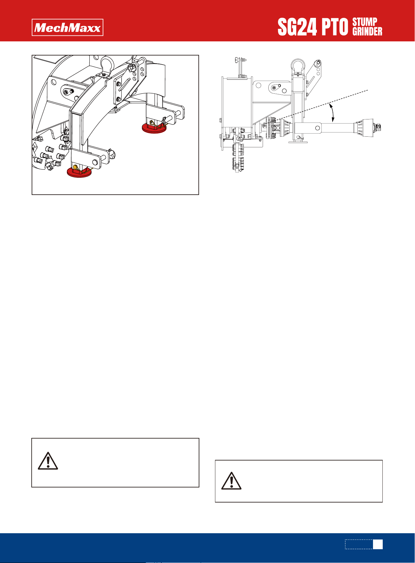
Prevent equipment damage.Operation with
pto shaft at a severe angle (over 17°) may
result in equipment damage.Adjust top link
pto shaft is as straight as possible.
Always turn offthe tractor and disengage
the PTO drive before getting off the seat
and approaching the cutting wheel.
▪ Reverse over a tree stump and lower the stump grinder
so it will remove 2" (50 mm) perpass. Always ensure
the grinder is cutting properly and not jumping around
erratically
▪ Once the stump is at ground level, continue to take up
to 2" (50 mm) deep passes until the stump and roots
are 4-6" (100-150 mm) below grade. Keep a watch out
for foreign objects below the soil like rocks or buried
metal. These can damage or break the teeth resulting in
poor grinding performance.
▪ During use, it is important to never let the stump grind-
er sway beyond an angle that will allow the PTO shaft to
separate. Do not operate the stump grinder with less
than 6" (150 mm) of overlap between the two halves of
the PTO shaft. If the stump grinder begins to sway, it
means either the tractor is advancing faster than the
grinder can remove material or that too much material
is being removed per pass. If this is observed, immedi-
ately stop moving forward and position the tractor and
stump grinder in a manner so that it is in the vertical
position. Take a slower pass and/or shallower cut if
necessary.
▪ Attach tractor to stump grinder. See tractor Operator's
Manual.
▪ Adjusting top link so that the driveshaft is straight in
the raised position will ensure that the driveshaft angle
is acceptable (17° or less) when the rotor is swung
back in the extreme cutting position.
FIRST TIME USER TIPS
17°
18
www.mechmaxx.com
STARTUP
Attach stump grinder to tractor. See Attaching Stump
Grinder to Tractor in this section.
Note: All cutting is done on the front side of the cutting
wheel, not the bottom of the wheel.
If the stump is on a grade, position tractor lower on the
grade with the cutting wheel on the stump grinder higher
up the grade.
Below is an approximate cutting time for the stump
shown in the image on the next page.
20 Hp tractor - 30 minutes
30 Hp tractor - 20 minutes
40 Hp tractor- 15 minutes
Operation should be smooth and grinding should be done
gradually. If the stump grinder is jumping or bouncing off
the stump, you are applying too much force. Applying too
much force will shorten the life of the cutting teeth and
may damage the stump grinder.
Entanglement in a rotating driveshaft can
cause serious injury or death.Keep tractor
shields and driveshaft shields in place at
all times. DO NOT operate without drive-
shaft guards.DO NOT wear loose fitting
clothing.
Prevent serious injury or death caused by
unexpected movement:
1. Park tractor on a level surface.
2. Engage tractor park brake.
3. Disengage PTO.
4. Shut off engine and remove key.
Never operate stump grinder when other
people are in the vicinity. Debris can be
thrown several feet from cutting area.
Keep all shields in place.
Never operate tractor when other people
are in the vicinity.Do not allow riders on
tractor.
Drilling, sawing, sanding or machining
wood products can expose you to wood
dust, a substance known to the State of
California to cause cancer.Avoid inhaling
wood dust or use a dust mask or other
safeguards for personal protection.
Wear an approved dust mask or respira-
tor.Follow local, state and federal regula-
tions.
Field Operation
19
www.mechmaxx.com
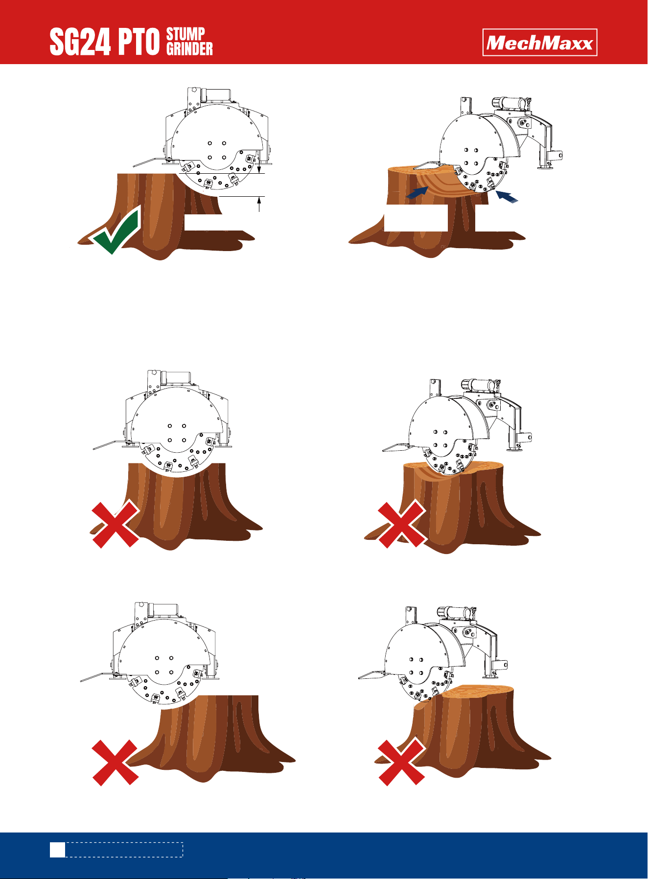
STUMP GRINDING PROCEDURE
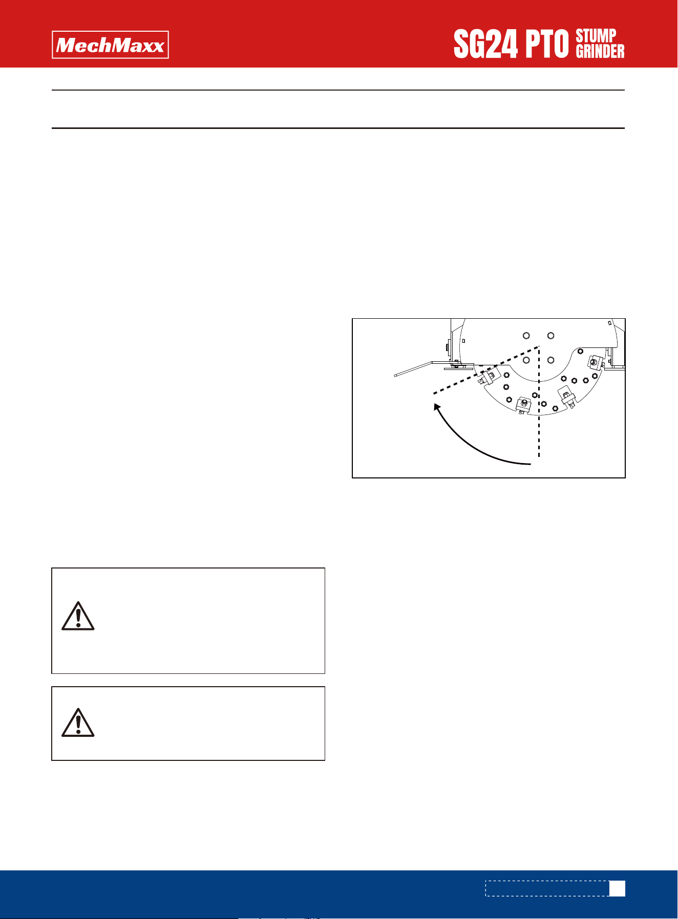
STUMP GRINDING PROCEDURE
The flywheel spins clockwise (when facing the rear of the
machine) with the effective cuttingarea in the lower-left
quadrant as shown below:
Observe all operating and safety instructions in thisman-
ual and those on the Stump Grinder before using this
machine.
Position the tractor for grinding a stump. The 3 pt. frame
should be lowered to the ground before grinding the
stump. Three point hitch lift arm stabilizer bars, sway
chains or sway blocks must be used to control side move-
ment of the stump grinder.
NOTE: Be sure parking stand is fully raised and fastened
with a locking pin before using the stump grinder.
Right-hand or left-hand reference is determined by stand-
ing at the rear of the stump grinder and facing in the
forward direction of travel of the power unit.
When engaging and disengaging the PTO, the engine
speed should always be low. Once the PTO is engagedand
ready to start cutting, raise the PTO speed to 540 RPM
and maintain throughout stump cutting operation.
ALWAYS operate the PTO at 540 RPM. This is necessary
to maintain proper wheel speed to obtain a clean, smooth
cut. Do not disengage PTO when the engine is at full PTO
RPM. Always bring the tractor engine to idle speed before
disengaging the PTO.
NOTE: To avoid damage to the clutch, the cutter wheel
should not be in contact with the stump when engaging
the PTO.
When grinding a tree stumpalways start from the right
side of the stum, moving incrementally to the left, pulling
the grinder straight forward through the stump on each
pass. When grindi softwoods like pine, spruce, or poplar, it
may be permissible to remove upwards of 2" (50 mm) of
material per pass. However, hardwoods like oak, ash, and
birch can be much more dense and the depth of grind may
only be up to 1" (25 mm). If the chassis is swaying like
described in the previous section, or the grinder is vibrat-
ing or bouncing, reduce the depth of cut or fee rate accord-
ingly.
Start the wheel on the edge of the stump and engage the
side hydraulic cylinder to make a light cut across the
stump.
When the first cutting pass is complete, raise the cutting
wheel slightly with the depth control cylinder and then
activate the side control cylinder to move the wheel back
to the start position.
Before moving the machine into position,
remove loose chunks of wood, stones,
wire, and other debris from the stump and
work area that might be thrown, causing
injury or damage.
When cutting a stump, the operator must
wear eye protection and must stay on the
power unit seat.
Effective
cutting area
20
www.mechmaxx.com
STUMP GRINDING PROCEDURE
INCORRECT GRINDING PROCEDURES
PULLING THROUGH THE CENTRE
GRINDING LEFT-TO-RIGHT
It is critical that the stump grinder is never pulled through the centre of a stump or ground from left-to-right. This will
induce severe vibration and cause the grinder to sway and bounce. It may also damage the machine and/or break teeth.
Depth of Grind
Left
Right
Left
Right
Direction of
Grind
Grind
Progression

MACHINE USE AND CARE
Always be sure the operator is familiar with proper safety
precautions and operation techniques before using
machine.
Do not force the machine. Machines do a better and
safer job when used in the manner for which they are
designed.
Storing the machine. When the machine is not in use,
store it in a dry, secure place or keep it well-covered and
out of the reach of children. Inspect the machine for good
working condition prior to storage and before each use.
Maintain the machine. It is recommended that the gener-
al condition of the machine be examined before it is used.
Keep your machine in good working order by adopting a
program of conscientious repair and maintenance in
accordance with the recommended procedures found in
this manual. If any abnormal vibrations or noise occurs,
turn the machine off immediately and have the problem
corrected before further use.
Cleaning. Use a pressure washer to clean the carbide
teeth while taking care not to pressure-wash the bearings
as this could introduce water into areas of the machine
that may cause malfunction or damage.
Use only accessories that are recommended by the manu-
facturer. Accessories that may be suitable for another
machine may create a risk of injury when used on this
machine.
Always operate the machine with all safety devices and
guards in place and in good working order. DO NOT modify
or make changes to safety devices. DO NOT operate the
machine if any safety devices or guards are missing or
inoperative.
Never leave the machine running unattended.
Never use the machine to grind anything other than
stumps or for any purpose other than grinding stumps as
described in this manual.
21
www.mechmaxx.com
MACHINE USE AND CARE
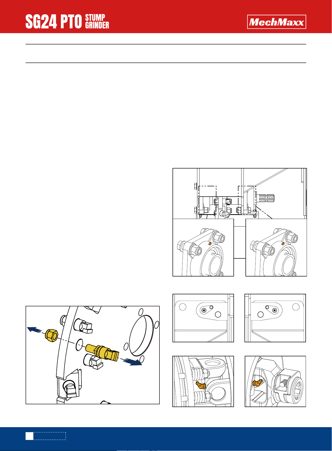
REPLACING TEETH
GREASING
MAINTENANCE
MAINTENANCE
Proper routine maintenance is critical to operator safety,
achieving proper stump grinding results, and prolonging
the life of the machine.
Before cleaning and/or any maintenance is performed on
the stump grinder, always turn off the tractor engine and
disconnect the PTO shaft.
Inspect the machine before each use for loose nuts and
worn cutting teeth and clean any debris that has built-up.
After 2 hours of operation, check for loose nuts and worn
cutting teeth. Tighten and replace as necessary.
Grease the bearings and the pivot pins on the main hous-
ing as needed before each use Do not over-grease the
bearings as this can blow out the seals and cause prema-
ture bearing failure. Refer to section, GREASING, for
information.
Inspect the clutch plates on the PTO shaft periodically to
ensure that they are not seized together. Refer to PTO
SHAFT CLUTCH RUN-IN in the SET UP PROCEDURES
section of the manual.
Disconnect the PTO shaft from the tractor and set the
stump grinder on a flat, level surface.
Remove the M16 X 1.5 lock nut (fine thread) from the
back of the tooth using a 24 mm wrench or socket.
Remove the worn cutting tooth while noting its orienta-
tion so that the replacement tooth will be installed in the
same manner.
Install the replacement tooth and lock nut using a torque
wrench set to 160 ft-lb (215 N-m).
The stump grinder has six (6) grease points: two (2)
flywheel bearings, two (2) hinge pins, and two (2) on the
PTO shaft. Check each grease point prior to use and add
grease as needed.
**Warning: These grease points come pre-greased from
the factory. Do not add grease to these points on a new
stump grinder. Over-greasing can damage the bearing
seals.**
Flywheel Shaft Bearings (Underside of Flywheel Housing)
Right Pivot Hinge
Left Pivot Hinge
22
www.mechmaxx.com
PTO Shaft: Slip Clutch End PTO Shaft: Tractor End

TROUBLESHOOTING
Remove material from cutting wheel.
Check to determine if the slip clutch is
hot. Use Caution: This Can Be Very Hot!
A hot clutch does NOT grip.
Slippage on the clutch occurs if there is
more power than the unit is rated for. A
bigger tractor can be used if it is idled
down as this will decrease the output
power of the engine.
Take smaller passes (less cutting) to
decrease the strain on the clutch.
Turn the flow control knob to a lower
number to reduce the strain on the slip
clutch.
PROBLEM CHECK SOLUTION
Cutting wheel does not spin. Cutting wheel jammed.
Slip clutch is slipping.
Remove jam from cutting wheel.
Check that driveshaft angle is not too
severe (17° or less).
Rotor stub shaft broken.
Replace stub shaft.
Tractor is not able to lift 3-point. Tractor is too small. Move link pins to the top position
on the stump grinder to add
leverage.
Cutting wheel cannot be lifted high
enough.
Stump too tall. Cut stump shorter.
Shorten top link on 3-point hitch.
Cutting wheel cannot be lowered
far enough.
Top link not correct length. Lengthen top link on 3-point hitch.
Cutting wheel does not have much
power.
Tractor too small.
Verify tractor is properly sized for
grinder.
Slip clutch is slipping.
23
www.mechmaxx.com
TROUBLESHOOTING

STORING GRINDER
REMOVE FROM STORAGE
▪ Store grinder in a dry place.
▪ Clean grinder thoroughly. Dirt and wood chips will
draw moisture and cause rust.
▪ Lubricate machine. (See Service and Maintenance
section.)necessary. (See Service and Maintenance
section.)
▪ Check condition of cutting teeth. Replace as
▪ Check for loose or missing hardware.
▪ Paint parts as necessary.
▪ Store PTO driveshaft off the ground.
▪ Review Operator's manual and check adjustments.
▪ Lubricate machine. (See Service and Maintenance
section.)
▪ If parts have been replaced, verify they run properly.
STORAGE
STORAGE
24
www.mechmaxx.com
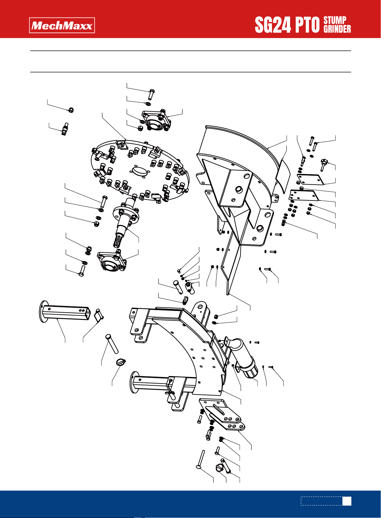
PARTS DIAGRAM
25
www.mechmaxx.com
7
10
15
29
2425
252423
20
22
26
21
12
15
161718
13
6
14
30
32
89
5
2827
4
5
5
3
2
1
31
42
333441
36
37
35
38
40
39
43
44
18
45
19
29
24 24 25
26
11 15
PARTS DIAGRAM

PARTS LIST
PARTS LIST
26
www.mechmaxx.com
PART NO. Description Qty
1
2
3
4
5
6
7
8
9
10
11
12
13
14
15
16
17
18
19
20
21
22
23
24
25
26
27
28
29
Main Weldment
Rubber Pad
Hex Head Bolt, Full Thread M8×30
Hex Lock Nut with Non-Metallic Insert, M8
Flat Washer 8
Support Weldment
Support Leg Weldment
Shaft Weldment
Straight Grease Fitting M6
Pin Shaft 22-170
Pin Shaft 20-110
Pin Shaft 19-125
Ear Plate Assembly Weldment
Large File Bucket
Ring O-Type Pin M11X45
Hex Head Bolt, Full Thread M12×40
Standard Elastic Washer (Assembly) 12
Flat Washer, Class C 12
Cutter Disc Weldment
Cutter Head
Cutter Spindle
Hex Lock Nut with Non-Metallic Insert, M16×1.5
Hex Head Bolt M16×65
Flat Washer, Class A 16
Hex Lock Nut with Non-Metallic Insert, M16
Square Housing Bearing
Hex Head Bolt, Full Thread M8×16
Standard Elastic Washer 8
Hex Head Bolt, Full Thread M16×55
1
1
3
3
8
1
2
2
2
2
2
1
1
1
5
4
4
5
1
34
1
34
4
24
12
2
2
2
8

27
www.mechmaxx.com
PART NO. Description Qty
30
31
32
33
34
35
36
37
38
39
40
41
42
43
44
45
Hex Head Bolt, Full Thread M6×20
Type 2 Hex Lock Nut with Non-Metallic Insert, M6
Flat Washer, Class C 6
Clamp Plate 2
Clamp Plate 1
Retaining Ring
Hex Head Bolt, Full Thread M10x50
Hex Head Bolt, Full Thread M10x35
Hex Nut M10
Hex Lock Nut with Non-Metallic Insert, M10
Flat Washer, Class A 10
Hand-Tightened Star Bolt
Baffle Plate
Round Head Square Neck Bolt M12×120
Type 2 Hex Lock Nut with Non-Metallic Insert, M12
Square Lock Pin
2
2
2
1
1
2
2
2
6
2
9
1
1
1
1
2
PARTS LIST