
04/2000 Martin Case Manual Version 7.20 Introduction
R&D International NV for Martin Professional AS
6
1 CHAPTER 1: Introduction
Thank you for selecting a Martin Case light controller. Martin Case light controllers offer
an enormous variety of tools helping light designers to create their most fabulous shows in
no time.
Originally, the controllers were designed to be used in combination with moving lights.
Today they can be used in the small disco club as well as on the big concerts. From this
software version, they offer the possibilities for the best theatrical jobs.
An enormous advantage is the software. You have to know only one software version to
control all Martin Case light controllers. From the smallest version, the Pro 1, to the most
extended version, the Pro 2 Plus, the same software is used. All functions available on the
Pro 2 Plus are also available on the Pro 1, only the access on the Pro 2 Plus is more direct
and easier to use.
Time pressure, no problem. The built-in Effects Generator saves a lot of programming
time. Furthermore, you have always direct access to each function of every fixture. There
have been spectacular shows in the past performed ‘on the fly’ with only some basic
programming.
04/2000 Martin Case Manual Version 7.20 Introduction
R&D International NV for Martin Professional AS
7
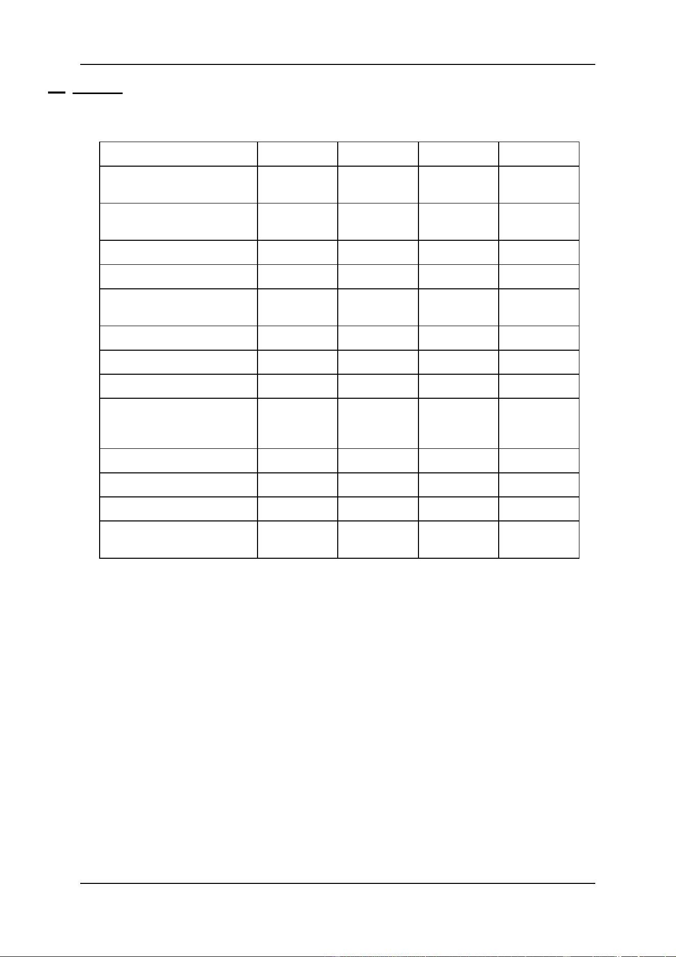
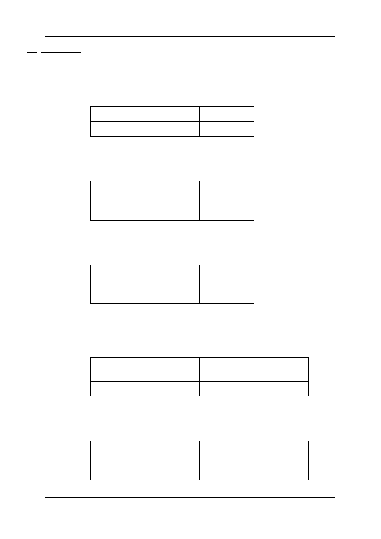
1.1 Features
Hardware
Pro 1 (*)
Pro 2 (*)
Pro 1+
Pro 2+
Protocols
DMX
-
out
DMX-in
DMX
-
out
DMX-in
DMX
-
out
DMX-in
DMX
-
out
DMX-in
Channels
(standard/Max)
512/1536
1024/2048
512/1536
1024/2048
Grand master
1
1
1
1
Flash master
1
1
1
1
Programmable
sub-master
2
2
2
2
Playback analogue faders
10 (**)
10 (**)
42
42
Sequence digital faders
-
12
-
12
Functions digital faders
-
16
-
16
Extra keys for:
Timing/playback mode/
Direct access (***)
-
-
Yes
Yes
SMPTE/MIDI
Option
Standard
Option
Standard
CD-ROM
Option
Standard
Option
Standard
Hard disk - Floppy disk
1 - 1
1 - 1
1 - 1
1 – 1
Trackerball
(on/off toggle)
1
1
1
1
(*) When the Pro 1 and the Pro 2 controllers are connected through the LINK with
a Playback Wing, they will have the same functionality as their +version with
the exception of the amount of channels.
(**) The 32 extra playbacks are accessible through an external midi keyboard.
(***) Those functions can be controlled on the Pro 1 en Pro 2 controllers, but a bit
more time-consuming.

04/2000 Martin Case Manual Version 7.20 Introduction
R&D International NV for Martin Professional AS
8
Software
FIXTUES
- Up to 700 fixtures with max 32 channels per fixture
- Library of more than 300 fixture types, grouped per manufacturer
- LEE, ROSCO, GAM filter library for CMY (RGB) fixtures
- Extended dip-switch information of the fixtures
- Repatch possibilities
- Protected functions like (reset, lamp-off, lamp-on)
- Direct access on each channel of every fixture
- Extended functions for dimmer-channels like: Dimmer-curves, multi-patch and
extended accessibility of dimmer-channels
- Possibility to group fixtures over 2 x 16 groups
- Adjustable DMX-timings for all outputs
PRESETS (70 x 4 types with extended functions)
- Pan/Tilt: includes Pan/Tilt, focus and dimmer information.
- Gobo: includes 4 gobo-wheels, 4 gobo-parameter fields, knifes (PAL1200),
iris, focus, zoom and prism information.
- Color: includes 4 color-wheels, color-parameter field, RGB and dimmer
information.
- Effect: includes all possible effects generator parameters.
- Every function can be enabled or disabled.
MEMORIES
- Maximum 4000 memories
- Every memory can include information of 700 fixtures of up to 32 channels, with
their effects generator parameters and their timing parameters
- Changes in preset-values are automatically recorded in the memories, if the
memories are built with presets
- Can be changed at any time
- Can be used in sequences and playbacks and can be called separately.
CUES
- Maximum 11,200 cues
- Per main-cue, 9 point cues
- Each cue can hold 1 cue-memory, 4 sequences and 42 playbacks
- Have transparent possibilities so that an activation of an other cue results in
replacing only the programmed functions (sequences, playbacks, cue-memory) of
the activated cue
- Have link possibilities to other cues

04/2000 Martin Case Manual Version 7.20 Introduction
R&D International NV for Martin Professional AS
9
- CUE MEMORY
o Every cue-memory can include information of 700 fixtures of up to 32
channels, with their effects generator parameters and their timing
parameters. The timing-parameters can be applied on the cue-memory
or on every single channel separately:
Delay-in time
Fade-in time
Delay-out time
Fade-out time
Link time
o Multi-select cue, or activating several cues simultaneous
o Auto-prepare cue-memory: when the dimmer closes in one cue, the
controller will look ahead and execute all programmed non-dimmer
channels until he finds a cue where the dimmer opens again.
o Auto-trace: when a cue is activated, the controller will gather all missing
channels in descending cue order.
- SEQUENCES
o Up to 4 sequences per cue
o Each sequence can hold 1 start-memory, 100 loop memories and 1 stop-
memory
o Have separate fade and wait-times.
o Can be activated/deactivated separately
o Can run forwards, backwards, in bounce (forwards and backwards) or at
random.
o Can be mutual synchronized
o Possibilities for auto-trigger, manual trigger and triggering in ‘learn the
beat mode’ (beat-step mode)
o Linking possibilities to other cues
- PLAYBACKS
o A playback is a memory to fade-in manually with:
A fader
A flash key
o Flash key functions:
Flash: with fade-in and fade-out time (adjustable separately)
Toggle: with fade-in and fade-out time (adjustable separately)
Kill: with fade-in and fade-out time (adjustable separately)
EFFECTS GENERATOR
- Up to 7 functions (10 for Pan/Tilt) per channel per fixture adjustable:
o Level, swing, speed, mode, delay, shift, wait (for non-Pan/Tilt channels).
o x-swing, y-swing, speed, mode, figure1, figure2, rotate, delay, shift, wait
(for Pan/Tilt channels).
- On Pan/Tilt channels, there is a choice out of a library of 49 different motion-
patterns.
- Pre-programmed combined effects with the effect macro functions like: Pan/Tilt
effects combined with dimmer effects or rainbow effect for RGB (CMY) fixtures.
- Possibility to spread the effect over more fixtures.

04/2000 Martin Case Manual Version 7.20 Introduction
R&D International NV for Martin Professional AS
10
OTHER FUNCTIONS (overview)
- 1 Grand master
- 1 flash master
- 2 programmable sub-masters
- Time-code
o Show-programming on time-code: SMPTE, CD-ROM, Internal clock or
manual.
- Midi
o Triggering of cues, cue-memories, sequences or playbacks through
midi-codes.
- Direct access of fixture-channels resulting in fast programming of colors, gobos,
functions… Direct access with digital fader belts on Pro 2 or Pro 2+ controllers.
- Absolute or relative programming of channel-values.
- Solo function for channel adjusting on the bigger shows.
- Freeze function to freeze fixtures, sequences, playbacks and cue-fading.
- Manual override mode
- Gel filter choice on filter number for RGB (CMY) fixtures
- Extended copy possibilities for memories and cues
- Extended load and save function to load or save shows
- Possibility to read memories from other controllers through DMX-IN
- Possibility to link MartinCase controllers (up to 41 with playback wing, up to 113
without) through DMX-IN
- Print or export possibility of stage layouts or patch lists.
04/2000 Martin Case Manual Version 7.20 Introduction
R&D International NV for Martin Professional AS
11
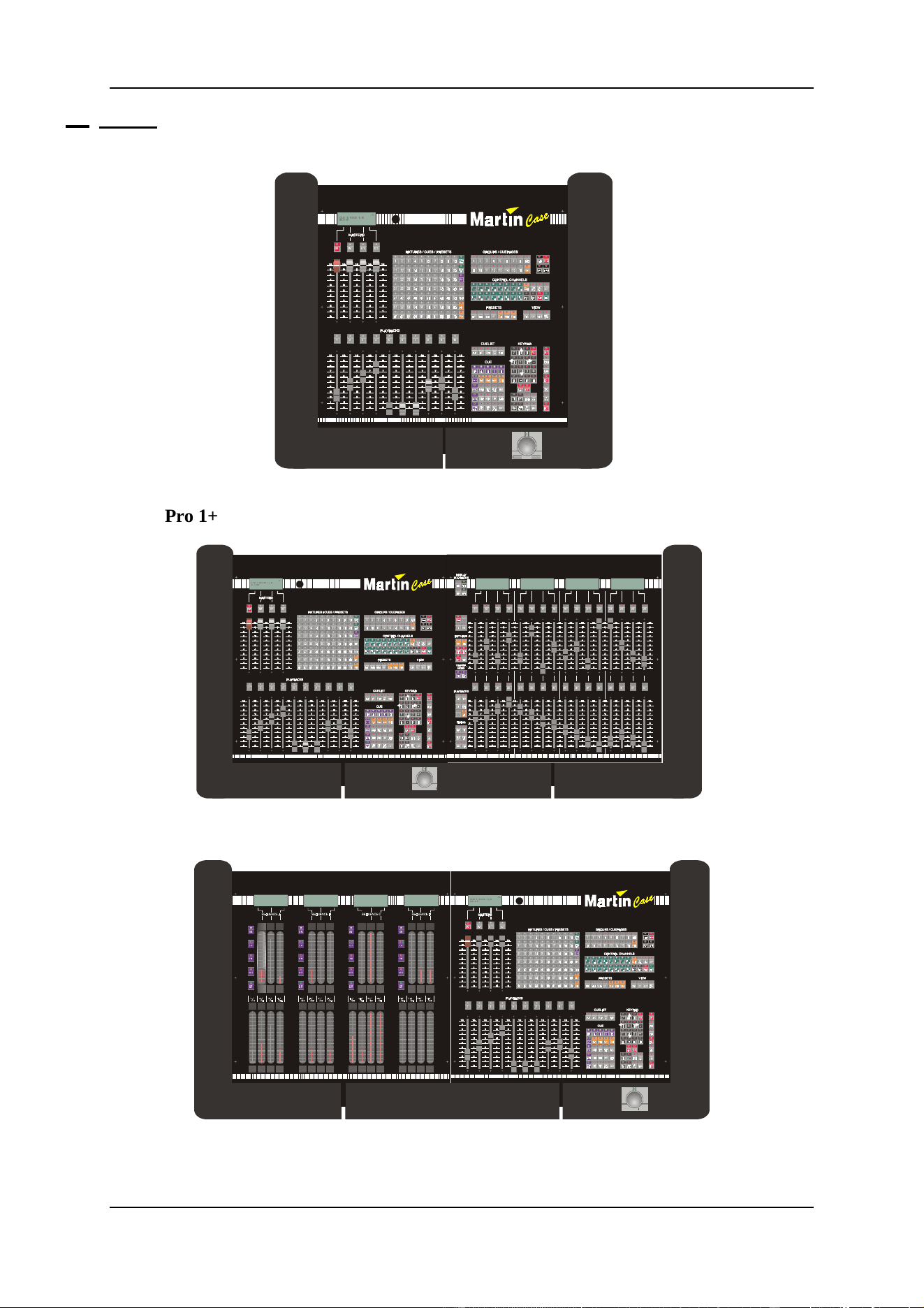
1.2 Models
Pro 1
6)0 6*0
?
9> EC5
3E5!@175!9C
Pro 1+
6)0 6*0
?
9> EC5
3E5 ! @175 ! 9C
Pro 2
21 21 21 21
6<1& 6<1& 6<1& 6<1&
$872 $872 $872 $872
67(3
%($7
67(3
%($7
67(3
%($7
67(3
%($7
! ! ! !
6)0 6*0
?
9> EC5
3E5 ! @1 75 ! 9C
04/2000 Martin Case Manual Version 7.20 Introduction
R&D International NV for Martin Professional AS
12
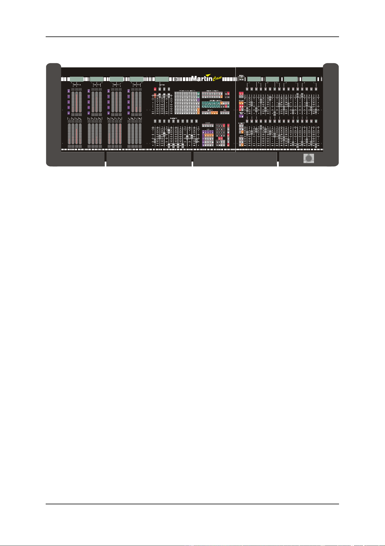
Pro 2+
6)0 6*0
(
D
VH
21 21 21 21
6<1& 6<1& 6<1 & 6<1&
$872 $872 $872 $872
67(3
%($7
67(3
%($7
67(3
%($7
67(3
%($7
! ! ! !
04/2000 Martin Case Manual Version 7.20 Introduction
R&D International NV for Martin Professional AS
13
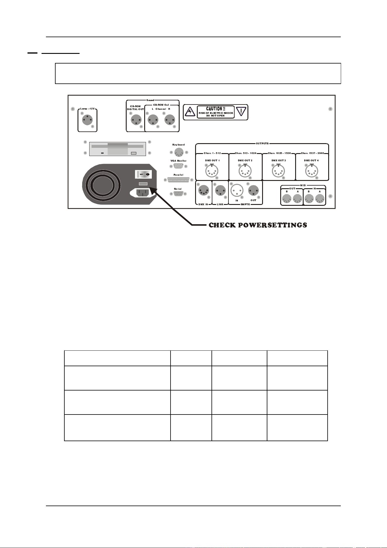
1.3 Connecting
WARNING: Adjust the voltage setting of your controller to your local AC power
supply before applying power.
Connect the power cable to AC power
Connect a standard VGA monitor to the ‘VGA Monitor’ output and connect its
power. Note: Some controllers don’t have a power output for the monitor.
Connect a standard PC keyboard (big connector) to the ‘Keyboard’ input.
Connect a data cable between the DMX or Martin output of the controller and the
fixtures.
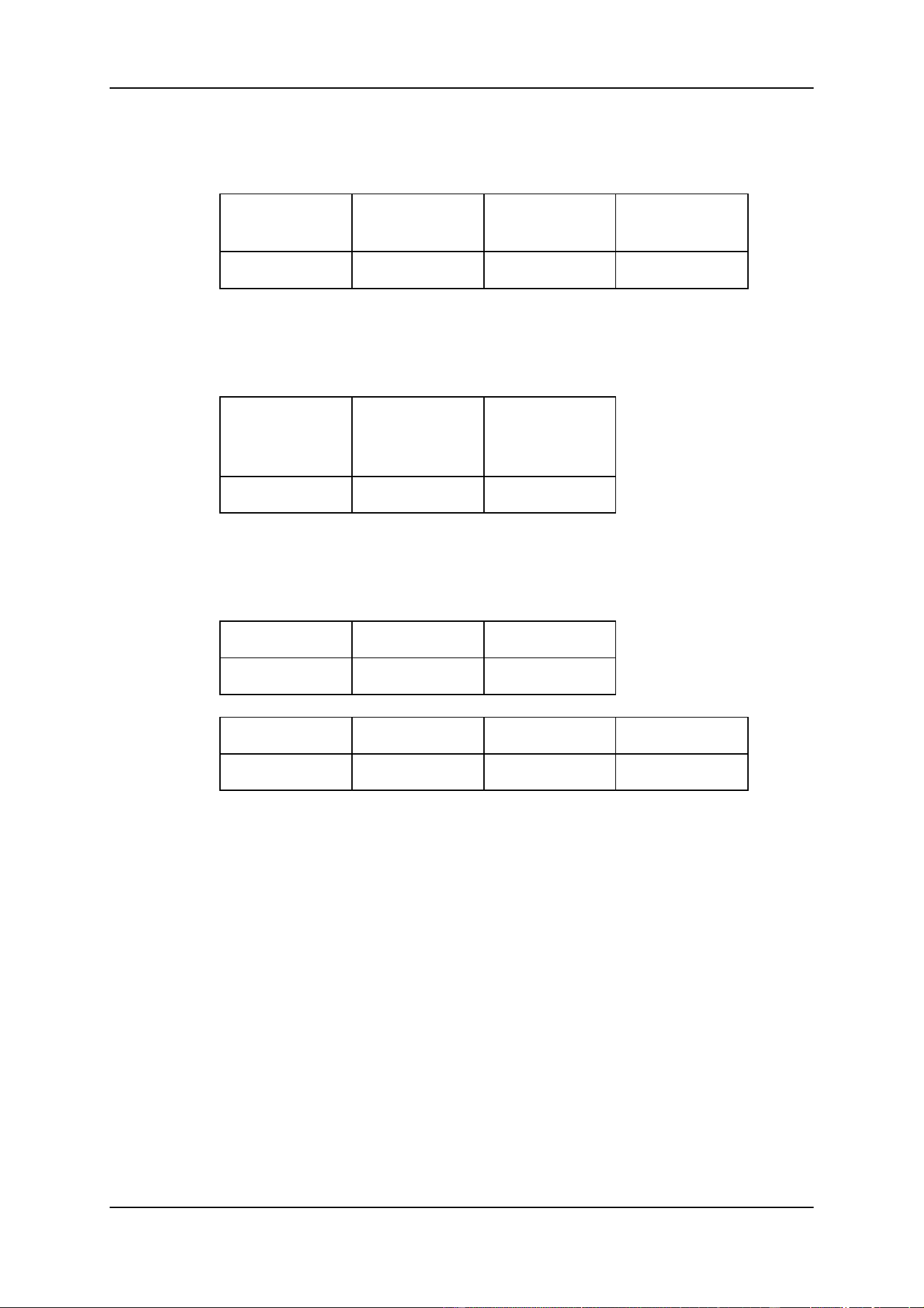
Note: Martin Case controllers use a 5-pin XLR connector for the DMX signal. With the
controller comes a 5-pin to 3-pin inverting and non-inverting adapter. See the table below
for the pin-connections.
DMX pin connections
GND
Signal – (cold)
Signal + (hot)
5 PIN XLR
output controller
PIN 1
PIN 2
PIN 3
3 PIN XLR
output adapter inverted
PIN 1
PIN 3
PIN 2
3 PIN XLR
output adapter non-inverted
PIN 1
PIN 2
PIN 3
Connect the supplied gooseneck lamp to the output (Lamp +12V)
Switch ON
34B?=
4979D1< ?ED
3XQ^^U\<B
C_e^T
?ED@EDC
9>
?ED
4=H 9> <9>; C=@D5
2121
=949
?ED 9>
;UiR_QbT
F71 =_^Yd_b
@QbQ\\U\
CUbYQ\
B9C; ?6 5<53DB93 C8?3;
4? >?D ?@5>
<Q]` !"F
3XQ^ ! %!"
4=H ?ED !
3XQ^ %!# ! "$
4=H ?ED "
3XQ^ ! "% !%#&
4=H ?ED #
3XQ^ !%#' " $(
4=H ?ED $
34B?= ?ed
3853; @?G5BC5DD9>7C
04/2000 Martin Case Manual Version 7.20 Introduction
R&D International NV for Martin Professional AS
14
1.4 Connections
Lamp +12V
Connection for a Gooseneck lamp (12V).
Lamp +12V
GND
+12V
3 Pin XLR
PIN 3
PIN 2
CD-ROM Digital out
Digital sound output of the build-in CD-ROM player.
CD-ROM
Digital out
GND
Signal
3 Pin XLR
PIN 1
PIN 2
CD-ROM OUT L and R
Analogue sound output left (L) and right (R) of the build-in CD-ROM player.
CD-ROM
L and R
GND
Signal
3 Pin XLR
PIN 1
PIN 2
DMX OUTPUT
DMX output for connection with the fixtures. Depending on the controller-type, there
are 1, 2, 3 or 4 DMX outputs.
DMX
OUTPUT
GND
Signal -
(cold)
Signal +
(hot)
5 Pin XLR
PIN 1
PIN 2
PIN 3
DMX INPUT
DMX input to read DMX signals coming from other controllers.
DMX
INPUT
GND
Signal -
(cold)
Signal +
(hot)
5 Pin XLR
PIN 1
PIN 2
PIN 3
04/2000 Martin Case Manual Version 7.20 Introduction
R&D International NV for Martin Professional AS
15
LINK OUTPUT
LINK output for connection with an extra playback wing.
LINK
OUTPUT
GND
Signal -
(cold)
Signal +
(hot)
3 Pin XLR
PIN 1
PIN 2
PIN 3
SMPTE IN - OUT
SMPTE in and output for time-code controlling of shows.
SMPTE
INPUT
OUTPUT
GND
Signal
3 Pin XLR
PIN 1
PIN 2
MIDI IN (A, B) OUT (A, B)
Standard MIDI in and outputs (channels A and B) to connect external MIDI devices.
MIDI IN
GND
Signal
5 pin DIN
PIN 4
PIN 5
MIDI OUT
+5V
Signal
Screen
5 pin DIN
PIN 4
PIN 5
PIN 2
Keyboard
Connection for a standard PC keyboard (5 pin DIN connector).
VGA Monitor
Connection for a standard VGA monitor.
Parallel
Connection for a printer.
Serial
To connect an external serial device like a mouse.
04/2000 Martin Case Manual Version 7.20 Menu
R&D International NV for Martin Professional AS
16
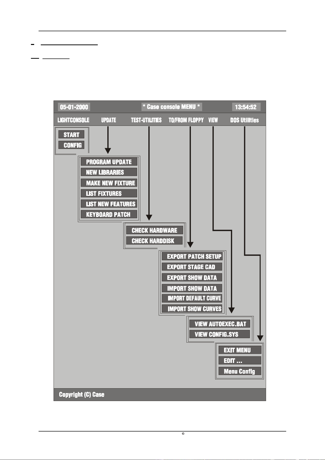
2 CHAPTER 2: Menu
2.1 Overview
When the main controlling program (logicase) is left with
[SHIFT] [SETUP]
(hold during
2 sec) next menu will appear:

04/2000 Martin Case Manual Version 7.20 Menu
R&D International NV for Martin Professional AS
17
2.2 LIGHTCONSOLE
START
This option starts the main controlling program (logicase) again.
CONFIG
To configure the system. When for example a DMX interface is added to the
controller, to expand the amount of DMX channels, it is necessary to run the
configuration.
When this option is selected, next menu will be shown:
CONFIGURATION LIGHTCONSOLE
CONFIGURATION CASECARDS
AUTOMATIC CONFIGURATION
CHECKING CONFIGURATION
CHANGE PASSWORD
Configuration lightconsole
To enable or disable functions like master faders, playback faders, digital faders,
speaker etc…
Configuration Casecards
Some older fixtures may react strange on the controllers DMX signal. With this
option, all DMX timings can be adapted. WARNING: IF YOU ARE NOT
FAMILIAR WITH DMX, DON’T CHANGE ANYTHING HERE, the
possibility exists that all fixtures will behave badly. To avoid this, the option is
protected by a password (telesoft). If however, the options are changed, use the
menu-item automatic configuration to default the DMX values.
This option is also used to prepare shows to be used on controllers with more
DMX channels. You won’t be able to control the fixtures, but the complete show
can be prepared.
Automatic Configuration
Is used to repair the configuration of the controller or to upgrade the number of
DMX channels when an extra DMX interface is added to the controller.
Checking Configuration
To test the configuration of the controller.

04/2000 Martin Case Manual Version 7.20 Menu
R&D International NV for Martin Professional AS
18
2.3 UPDATE
PROGRAM UPDATE
To update the controller with new software: put the floppy(ies) with the new version in
the floppy-drive and use this option.
The controller will automatically make a backup of the old version and will install the
new version. The option ‘List new features’ gives an overview of new items. RESET
the controller after updating.
Rem. : Regularly check both sites below for new software versions:
http://www.martin.dk
Or the Case site:
http://www.caseconsole.com
Please follow the instructions on the site to install new versions.
NEW LIBRARIES
Each month new fixtures are added to the library. The latest libraries are always
accessible on the Martin or Case sites. The option ‘List fixtures’ gives an overview of
all fixtures installed in the controllers library.
Rem.: A library update will always update all fixtures.
MAKE NEW FIXTURE
Not yet in use.
KEYBOARD PATCH
After a software update or after a complete new installation, the keyboard patch file of
the controller may be changed too. This causes some keys like the grand master flash
key to behave strange, sometimes the front panel keyboard may be mixed up on older
controllers. Use this option to select another keyboard patch file.
If an older controller was upgraded with the playback wing link, and the playback
keys don’t work, select in this option keyboard 4.
2.4 TEST-UTILITIES
CHECK HARDWARE
To check the hardware functions of the controller.
CHECK HARDDISK
To check the internal hard disk on errors.

04/2000 Martin Case Manual Version 7.20 Menu
R&D International NV for Martin Professional AS
19
2.5 TO/FROM FLOPPY
EXPORT PATCH SETUP
To copy the patch setup, exported in the SETUP (see chapter SETUP) to a floppy. The
file can be used on a Windows PC.
EXPORT STAGE CAD
To copy the STAGE LAYOUT in BMP format, exported in the SETUP (see chapter
SETUP), to a floppy. The file can be used on a Windows PC.
EXPORT / IMPORT SHOWDATA
In rare occasions, on very big shows, a message ‘NOT ENOUGH DISKSPACE’ can
appear on the screen when saving a show to a floppy. If this happens, use this menu
option to save the show on multiple floppies.
To load a show from multiple floppies, use the import option.
IMPORT DEFAULT CURVE/ IMPORT SHOW CURVES
With the Windows program ‘Logicurve’, dimmer curves can be adapted externally. Use
this option to import the curves. If the default option is used, the curves are used with
every new show. If the show option is used, only the current show will use the curves.
The Windows program ‘Logicurve’ can be downloaded free on both earlier mentioned
sites.
2.6 VIEW
To view the system files of the controller.
2.7 DOS UTILITIES
To edit files and to leave the menu.
04/2000 Martin Case Manual Version 7.20 Using the manual
R&D International NV for Martin Professional AS
20
3 CHAPTER 3: Using the manual
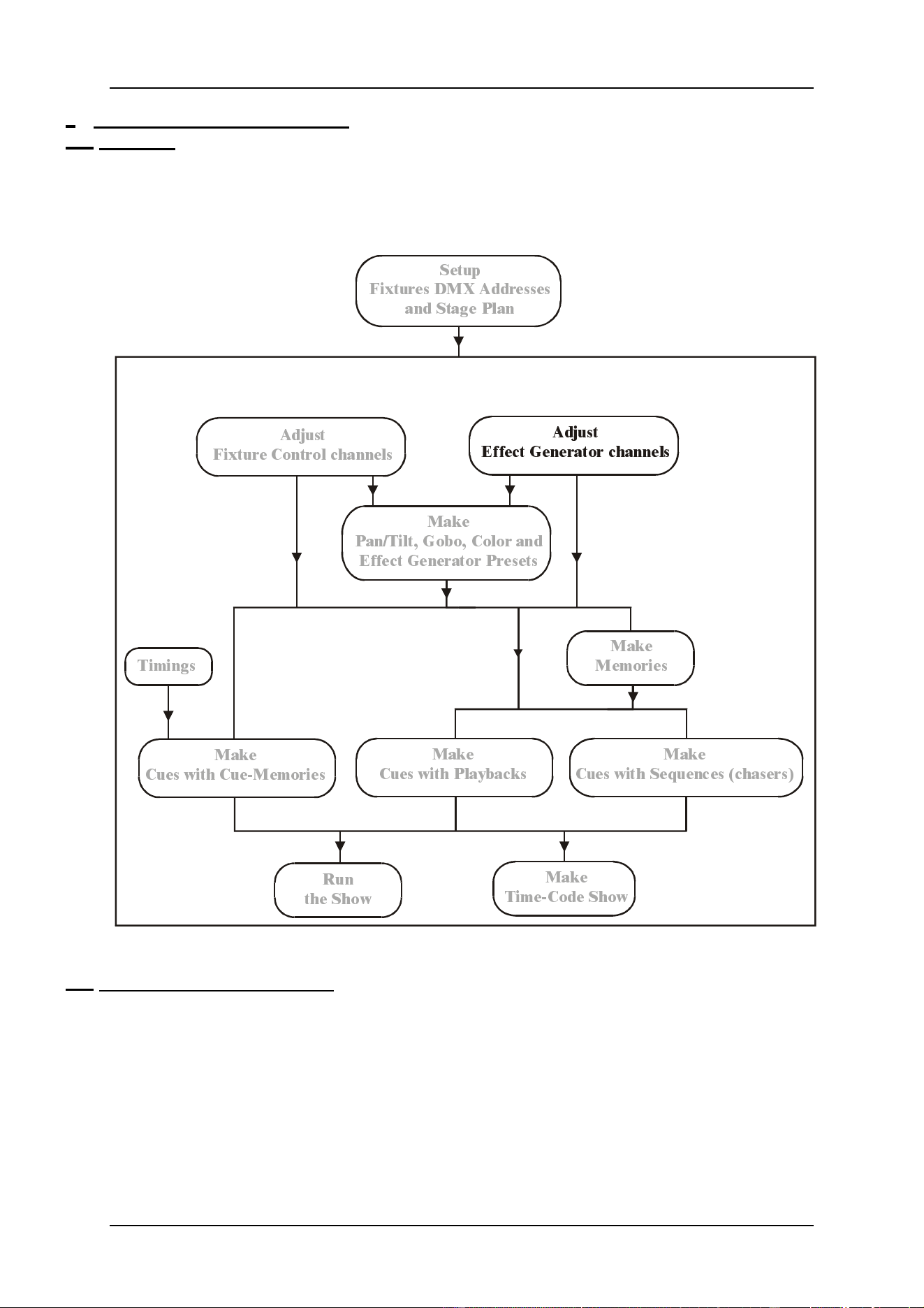
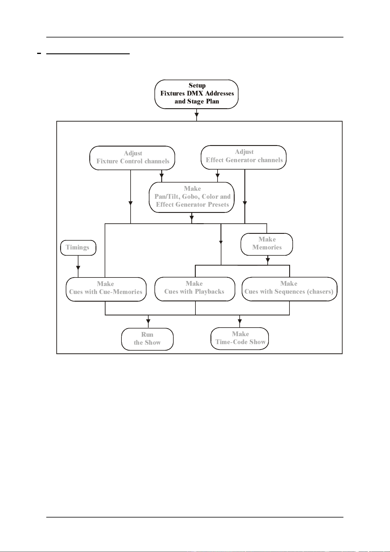
3.1. Overview
Each chapter begins with a diagram to show you which point you have reached when you are
studying the controller.
This example shows that the chapter explains the effects generator.
3.2. Experienced user or beginner
In this manual, we try to group everything per chapter. Because of this, it can happen that
sometimes items, difficult to understand for new users, will be explained. New users are
advised to skip those items until he has some experience in using the controller. The sign
{EXP} in the margin or in the heading of the chapter stands for experienced user and it means
that the item or the chapter is only to be read by experienced users.
6HWXS
)L[WXUHV '0; $GGUHVVHV
DQG 6WDJH 3ODQ
$GMXVW
)L[WXUH &RQWURO FKDQQHOV
$GMXVW
(IIHFW *HQHUDWRU FKDQQHOV
0DNH
3DQ7LOW *RER &RORU DQG
(IIHFW *HQHUDWRU 3UHVHW V
0DNH
&XHV ZLWK &XH0HPRULHV
5XQ
WKH 6KRZ
0DNH
7LPH&RGH 6KRZ
0DNH
&XHV ZLWK 3OD\EDF NV
0DNH
&XHV ZLWK 6HTXHQFHV FKDVHUV
0DNH
0HPRULHV
7LPLQJV

04/2000 Martin Case Manual Version 7.20 Using the manual
R&D International NV for Martin Professional AS
21
3.3. Use of the keys and the denotation in this manual
The denotation of a key:
[KEY]
When an item has been explained in a previous chapter, a description will replace the key
actions:
[Description]
A PLUS sign between the keys will mark that more keys have to be selected simultaneous:
[KEY 1] + [KEY 2]
If the keys have to be selected one by one, they will be separated by a space:
[KEY 1] [KEY 2]
Some keys have the same function or meaning, like the big key matrix beginning with key 1
and ending with key 70. Those are denoted as:
[1…70]
This means, ‘press one of the keys in the key matrix 1, 2, 3, …. , 70 (Fixtures/Cues/Presets)’
[1…16]
This means, ‘press one of the keys in the key matrix 1, 2, 3, … , 16 (Groups/Cuepages)’
[1/17…16/32]
Means: ‘press one of the keys in the key matrix [1/17] … [16/32] (Control channels)’.
Some of the keys like the [CLR] or the [P&T] key, can be found more than once on the front
panel keyboard. To indicate the correct key, an explanation is given between brackets ().
[CLR (Presets)]
An example:
[1…70] [1…70] …. [1…70]
Select some keys in the key matrix 1…70. This is the same as: select some fixtures (see
chapter ‘fixtures and control channels’). Since we know now how to select fixtures, the next
paragraph won’t explain this again and the fixture selection is indicated by:
[Select fixtures] [STORE (groups/cuepages)] + [1…16]
So this means: select some fixtures and press the [STORE] key (in groups/cuepages)
simultaneous with on of the key in the key matrix 1…16.

04/2000 Martin Case Manual Version 7.20 Using the manual
R&D International NV for Martin Professional AS
22
3.4. Keyboard help
The controller keyboard is equipped with a build-in HELP function by means of LEDs.
Every time when a function is called, the LEDs of the keys, which can be used with this
function, will blink.
Example: Select the [EDIT (CUES)] key. All LEDs of the keys involved in the edit function
will blink orange.
3.5. Important remarks and actions to be taken
Bold marked texts indicate an important remark or a tip.
Bold and italic or italic texts indicate an action to be executed by the user.
3.6. Overview
The ‘appendix’ of this manual holds some fold up pages with an overview of the front-panel
keys of the controller.
3.7. Example show
There are 2 example shows:
The first show ‘getstart.cmp’ gives examples for the ‘getting started’ manual.
The second show ‘manual72.cmp’ holds the examples for this manual.
If an MSD (Martin Show Designer) is connected to the controller, all examples can be seen
‘in live’. For both shows, an MSD version is available.
Loading of the example show ‘MANUAL72’:
When the main program is started, load the show by pressing the [LOAD] key.
Step 1: Press [LOAD (hold for 2 secs)]. In the lower left corner of the screen, next message
will appear: ‘1 = LOAD INTERNAL 2 = LOAD EXTERNAL’
Step 2: Select [1 (keypad)] to load the show from the internal hard disk or select [2 (keypad)]
to load the show from a floppy disk.
Step 3: Type the name MANUAL72 or highlight the name MANUAL72 using the [2
↓
] key.
Step 4: Press [RET] (in case you’ve used the [2
↓
] key press 2 x [RET]). The show will
appear within a few seconds.
04/2000 Martin Case Manual Version 7.20 Setup
R&D International NV for Martin Professional AS
23
4 CHAPTER 4: The Setup
6HWXS
)L[WXUHV '0; $GGUHVVHV
DQG 6WDJH 3ODQ
$GMXVW
)L[WXUH &RQWURO FKDQQHOV
$GMXVW
(IIHFW *HQHUDWRU FKDQQHOV
0DNH
3DQ7LOW *RER &RORU DQG
(IIHFW *HQHUDWRU 3UHVHWV
0DNH
&XHV ZLWK &XH0HPRULHV
5XQ
WKH 6KRZ
0DNH
7LPH&RGH 6KRZ
0DNH
&XHV ZLWK 3OD\EDFNV
0DNH
&XHV ZLWK 6HTXHQFHV FKDVHUV
0DNH
0HPRULHV
7LPLQJV
04/2000 Martin Case Manual Version 7.20 Setup
R&D International NV for Martin Professional AS
24
6HOHFWPDQXIDFWXUHU
6HOHFWIL[WXUHW\SH
6HOHFWIL[WXUHSDJH
6HOHFW'0;RXWSXW
6HOHFW'0;DGGUHVV
3ODFHIL[WXUHRQVWDJH
5RWDWHIL[WXUH
([LWDQGVDY H6(783
SETUP BASICS
04/2000 Martin Case Manual Version 7.20 Setup
R&D International NV for Martin Professional AS
25
4.1. Start-up
When the controller is powered on, or when the option ‘START’ is chosen from the menu,
the main-program will show up.
To control lights with the controller, first the STAGE has to be built. The corresponding
fixtures with their corresponding DMX addresses have to be set up.
The SETUP program is used to:
- modify the start-up options of the main program
- draw the stage layout
- set up the fixtures from the library
- set up fixture addresses
- re-patch fixture channels and fixture numbers
- select the dimmer curves for dimmer channels
- activate/deactivate dimmer channels for dimmer programming
- link controllers
- select the RGB (CMY) library
- print and export the patch setup and the stage layout
[SETUP]
The setup program is started from the main program by selecting the [SETUP] key (hold it
during 2 sec).
2 key LEDs will start blinking now on the keypad. There are 2 possibilities:
- Select [1] to start the fixture setup program
- Select [2] to modify the start-up options and the default values for the main
program
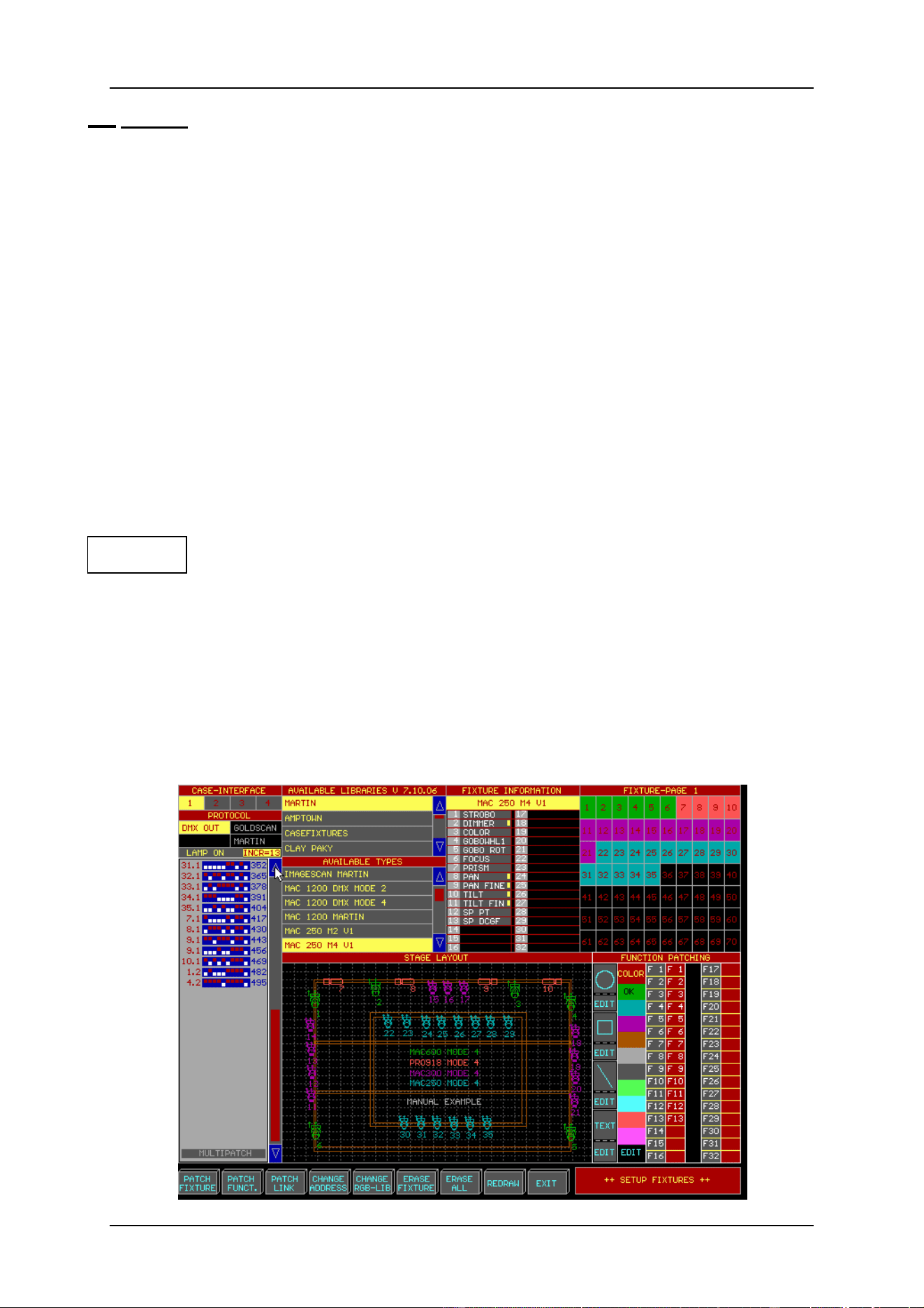
If option [1] is selected, the screen below will appear:
04/2000 Martin Case Manual Version 7.20 Setup
R&D International NV for Martin Professional AS
26
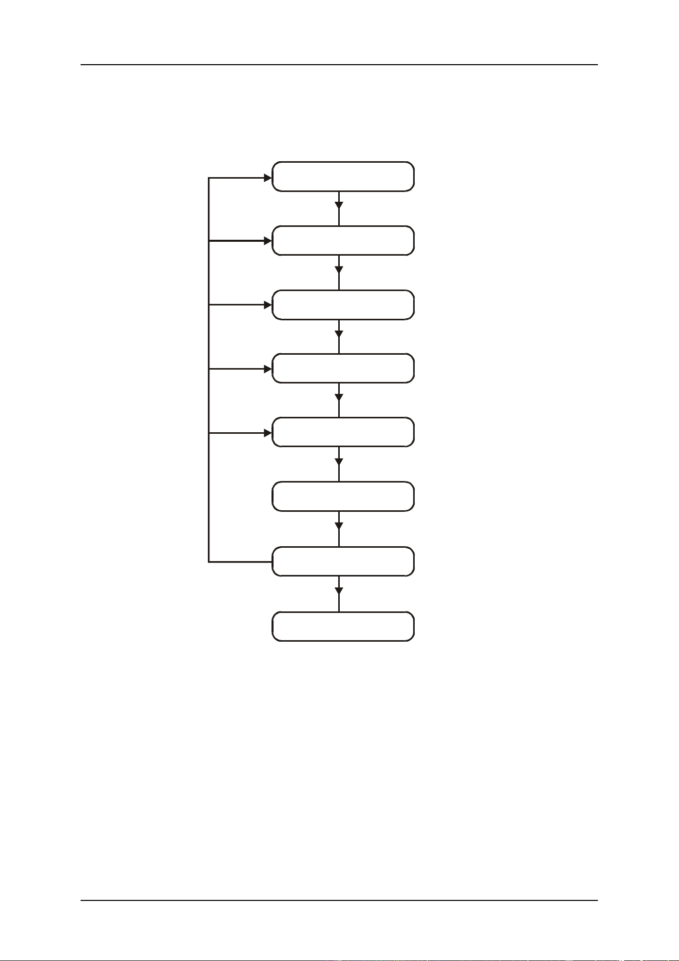
4.2. Set up fixtures
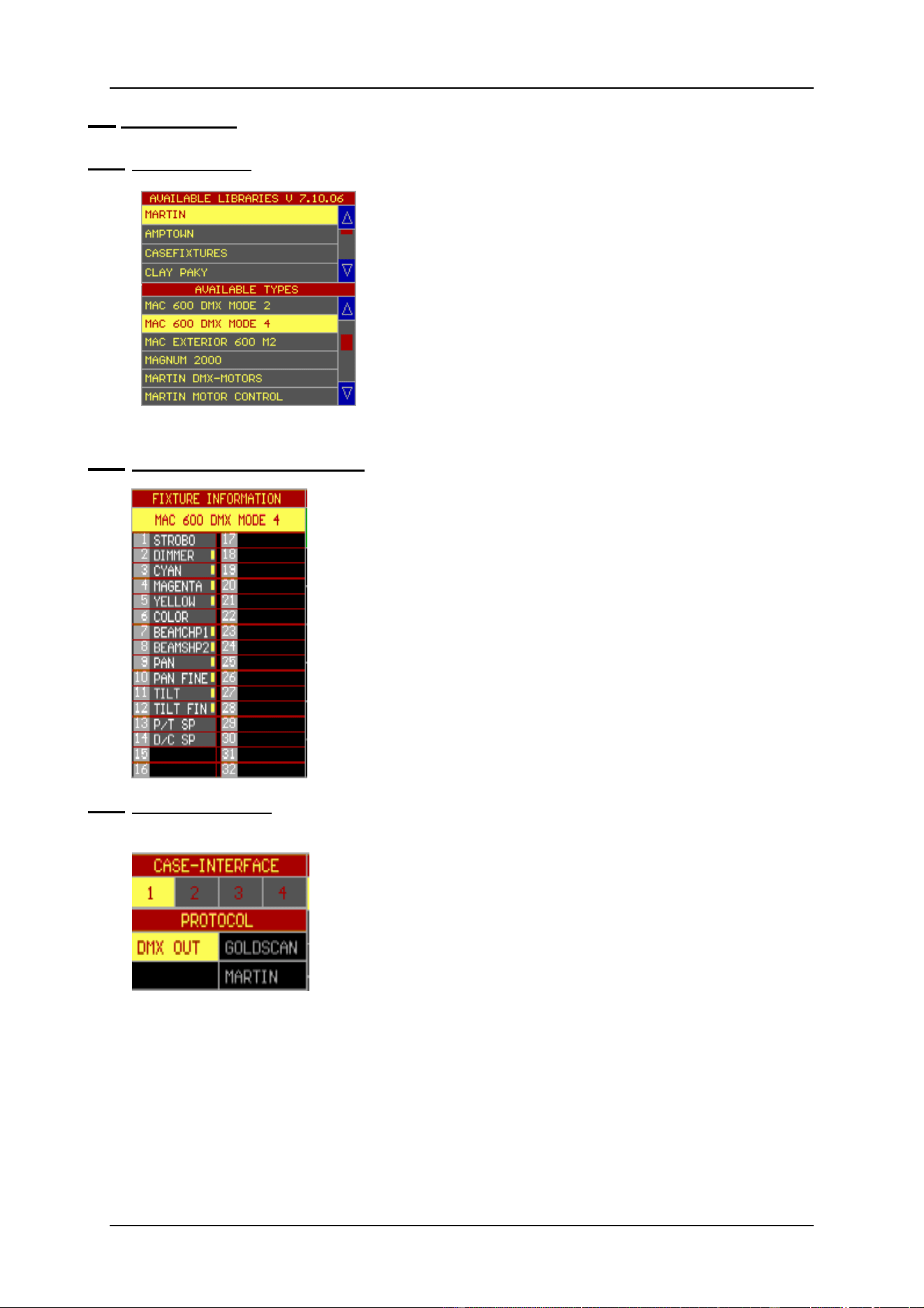
4.2.1 Fixture library
To place a fixture on the stage, the fixture has to be chosen
from its library.
First select a fixture page with the [Fixture PgUp] or
[Fixture PgDn] keys. (There is a choice between 10 pages
of 70 fixtures).
Then select a manufacturer, for example Martin, and
select a fixture type.
Suppose we will build a stage with 6 MAC600 in mode .4
4.2.2 Fixture Information Window
From the moment, the fixture type is selected, its fixture channels
will appear in the ‘Fixture Information’ window.
In this example, a MAC600 (mode 4) was selected. This fixture
has 14 functions or channels. A yellow square behind the channel
indicates that the channel has fading possibilities
4.2.3 Interface window
This window reveals the INTERFACE outputs and for older
controllers also the PROTOCOLS. Select with the trackerball an
output and a protocol. Output 1 is the same as channels 1 to 512,
output 2 = channels 513 to 1024, output 3 = channels 1025 to
1536 and output 4 = channels 1537 to 2048.
A yellow box denotes the selected output, a gray box means a
possible choice and a black box indicates that the option is not
installed.
Rem. 1: It is not always possible to select a protocol, since the protocol depends on the
fixture type. Also, on new controllers, only the DMX OUT protocol is available.
Rem. 2: Depending on the configuration, all output boxes may be gray, indicating that all
outputs are available, but as explained in the menu chapter, a controller can be set up for
2048 channels with only 1 physical output available.

04/2000 Martin Case Manual Version 7.20 Setup
R&D International NV for Martin Professional AS
27
4.2.4 Dipswitch window
From this window, the fixture addresses are selected. The
dipswitches represent address switch positions on the fixtures. New
fixtures today use displays.
The numbers on the left represent the fixture patch number, as
they appear in the stage layout window, and the stage page or
fixture page where it is placed.
Patch number.Stage page
The numbers on the right represent fixture addresses. The
addresses increase per number of fixture channels. By clicking the
INC=14 box, the addresses will increase by 1 (the box will show
INC=1).
When the fixture type, the output and the protocol are selected, slide
with the trackerball over the dipswitches. When the dipswitch
address corresponds with the physical fixture address, the fixture
will respond with a Pan/Tilt at half its values, dimmer open, no
gobo and no color. A gray box indicates an address not selected yet,
a light blue box indicates a partially used address section and a dark
blue box indicates that the address section is completely taken.
There is a second option to select the address by means of the
keypad: select: [@] number [RET].
If the fixture is equipped with a lamp-on/off function, the command
LAMP ON is executed by selecting the LAMP ON box before the
fixture address is chosen.
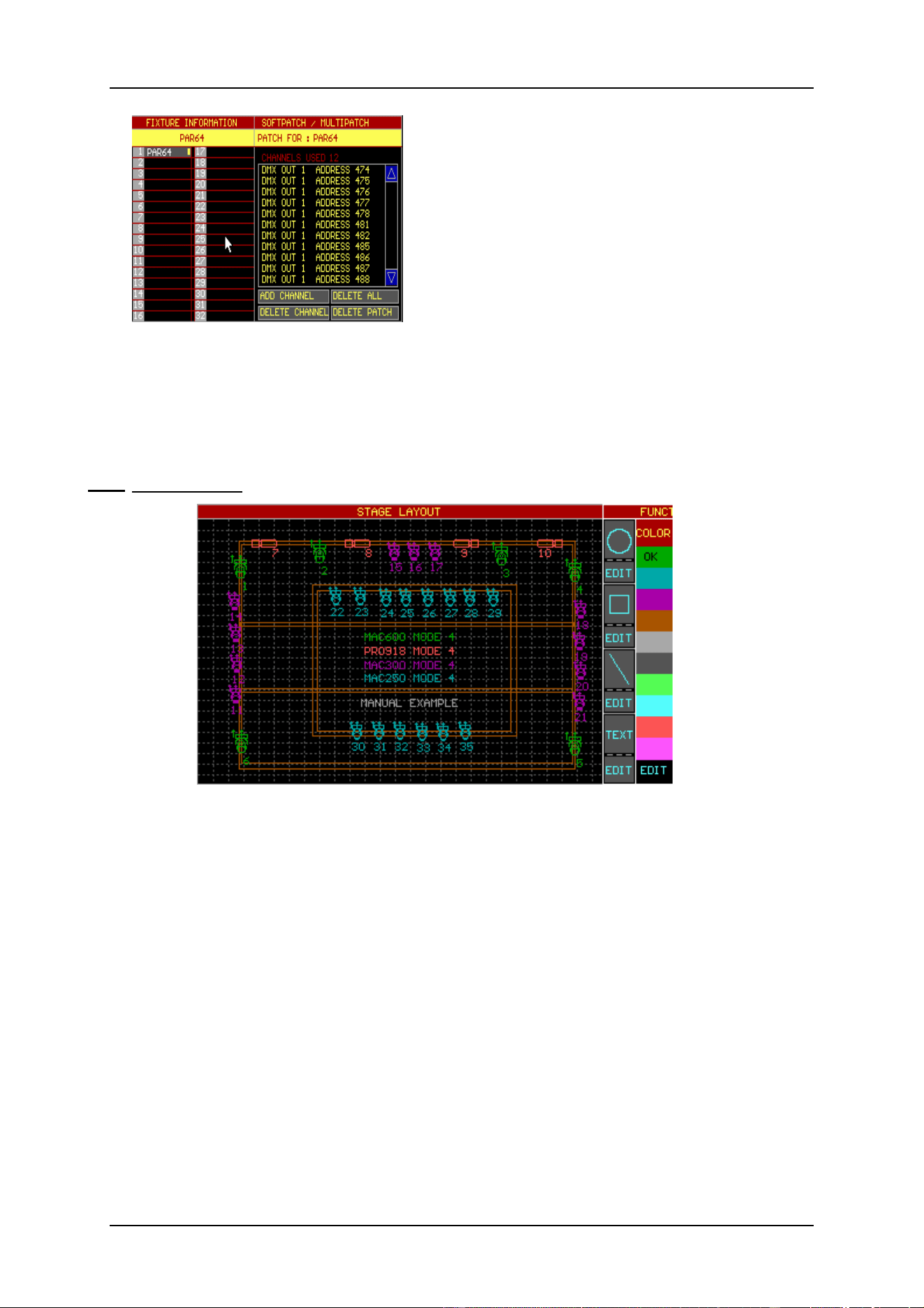
4.2.5 {EXP} Multipatch/Softpatch
From this software version (7.20), there are multipatch or softpatch possibilities for
certain fixture types like dimmers (out of the dimmerpacks library) or spots (out of the
spots library). There are also some fixture types, like the VL5, that have a dimmer channel
that is separately addressable. When those types are selected, the softpatch window will
open automatically.
Multipatch/Softpatch gives the possibility to:
- individually address all channels of a dimmerpack
- assign multiple addresses to one singe dimmerchannel
04/2000 Martin Case Manual Version 7.20 Setup
R&D International NV for Martin Professional AS
28
When a dimmer or spot is taken, and instead of
selecting an address, the MULTIPATCH function is
activated, a softpatch window will open.
Place the fixture somewhere in the Stage window.
Select a channel from the fixture information
window and select ADD CHANNEL. Assign an
address (see previous paragraph) to the channel.
The channel will appear in the softpatch window.
With the add channel function, multiple addresses
can now be assigned to one single channel. If an
address has to be deleted from the window, select its address line in the softpatch window
and click the DELETE CHANNEL.
A quick and shorter method to assign addresses: Select a channel from the fixture
information window and press [@] [address (keypad)] [RET] or in case addresses 10 to
20 need to be assigned to the channel: [@] [10 (keypad)] [THRU] [20 (keypad)] [RET]
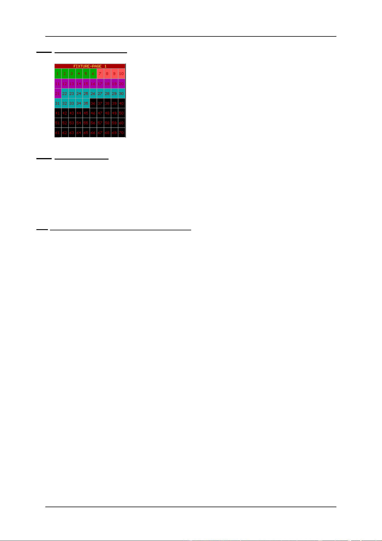
4.2.6 Stage window
It is important that the Pan/Tilt directions of the fixture correspond with the directions
made with the trackerball. To apply this correspondence the fixture can be turned in 9
possible positions with the keypad keys [1…9]. The fixture is now ready to be positioned
somewhere on the stage by confirming its position with the left trackerball key.
It is always possible to move the fixture by re-selecting it in the stage window.
When the same fixture type, with successive addresses, has to be set up, it is faster to select
the [next] key after assigning the first address to the first fixture.
It is also possible to draw circles, rectangles and lines in the stage layout window. In
addition, some texts can be added. Afterwards, everything can be edited with their EDIT
function.
By default, everything that is placed in the stage window has a green color. To keep
everything well organized, it is better to select first a color before a fixture is set up or
before drawing lines etc… It is always possible to change colors afterwards with the EDIT
functions.
04/2000 Martin Case Manual Version 7.20 Setup
R&D International NV for Martin Professional AS
29
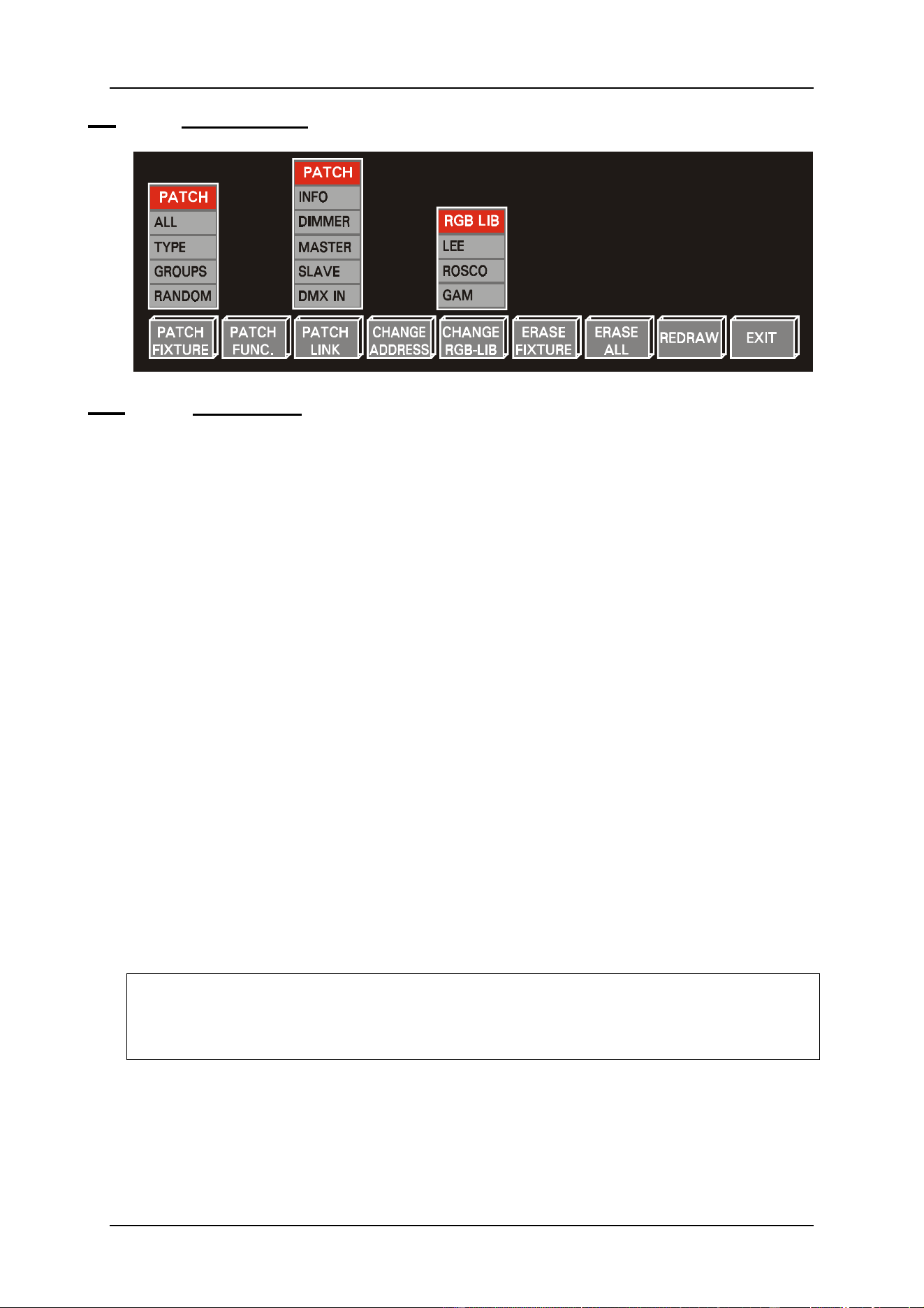
4.2.7 Fixture patch window
From the moment the fixture is placed in the stage window, its
number with its color will also appear in the fixture patch
window.
This same window will also be displayed in the main program.
The numbers 1…70 represent the fixture numbers on the selected
fixture page as they appear in the stage layout window
4.2.8 Saving the setup
Click on the EXIT box or select (and hold for 2 sec) the [SETUP] key.
Click the SAVE box or select key [1], NOT SAVE or key [2] or [ESC] to abort.
It is impossible to leave the SETUP as long as there are patch faults (overlapping
addresses).
4.3. Trackerball and keys in the setup program
Trackerball
Only the 2 upper trackerball keys have a function in the setup program:
- LEFT KEY: apply
- RIGHT KEY: abort
Front-panel keys
In general: When a function has been selected, the LEDs of the keys
belonging to the selected function will blink.
Keypad [2] and [8]: Line down, up, like address down, address up.
Keypad [1 ... 9]: Rotating fixtures
Manually assigning addresses followed by [RET]
[PgUp] en [PgDn]: Page up, Page down: for example address page up or address
page down in the dipswitch window.
[Fixture PgUp] and
[Fixture PgDn]: Selecting a fixture page.
[ESC]: Abort
[@]: Select this key first when values need to be assigned, for
example when assigning DMX addresses.
04/2000 Martin Case Manual Version 7.20 Setup
R&D International NV for Martin Professional AS
30
4.4. {EXP} Other functions
4.4.1 {EXP} Patch Fixture
This is a re-patch function or re-number function for fixtures already being placed on the
stage.
All
All fixture numbers change starting from 1.
First, the fixture type, of the fixture that has to become fixture 1, has to be selected.
Then the fixtures, within the selected type, have to be clicked in successive order.
Type
To change the fixture order within one fixture type.
First, select the type (for example MAC300 or MAC600), and then click the fixture
that has to become first within the selected type.
Groups
To renumber the fixtures by selecting complete groups of fixtures.
Select in successive order the groups. The fixtures will be renumbered automatically.
Random
To break the fixture type ordering. Every fixture can be ordered as wished.
The fixtures are selected in successive order.
Tip: It is also possible to re-patch fixtures by using the DRAG AND DROP function with
the trackerball. Just click the fixture number, in the fixture patch window, with the
left trackerball key and hold it. Drag the number to another position and drop it by
releasing the key.
04/2000 Martin Case Manual Version 7.20 Setup
R&D International NV for Martin Professional AS
31
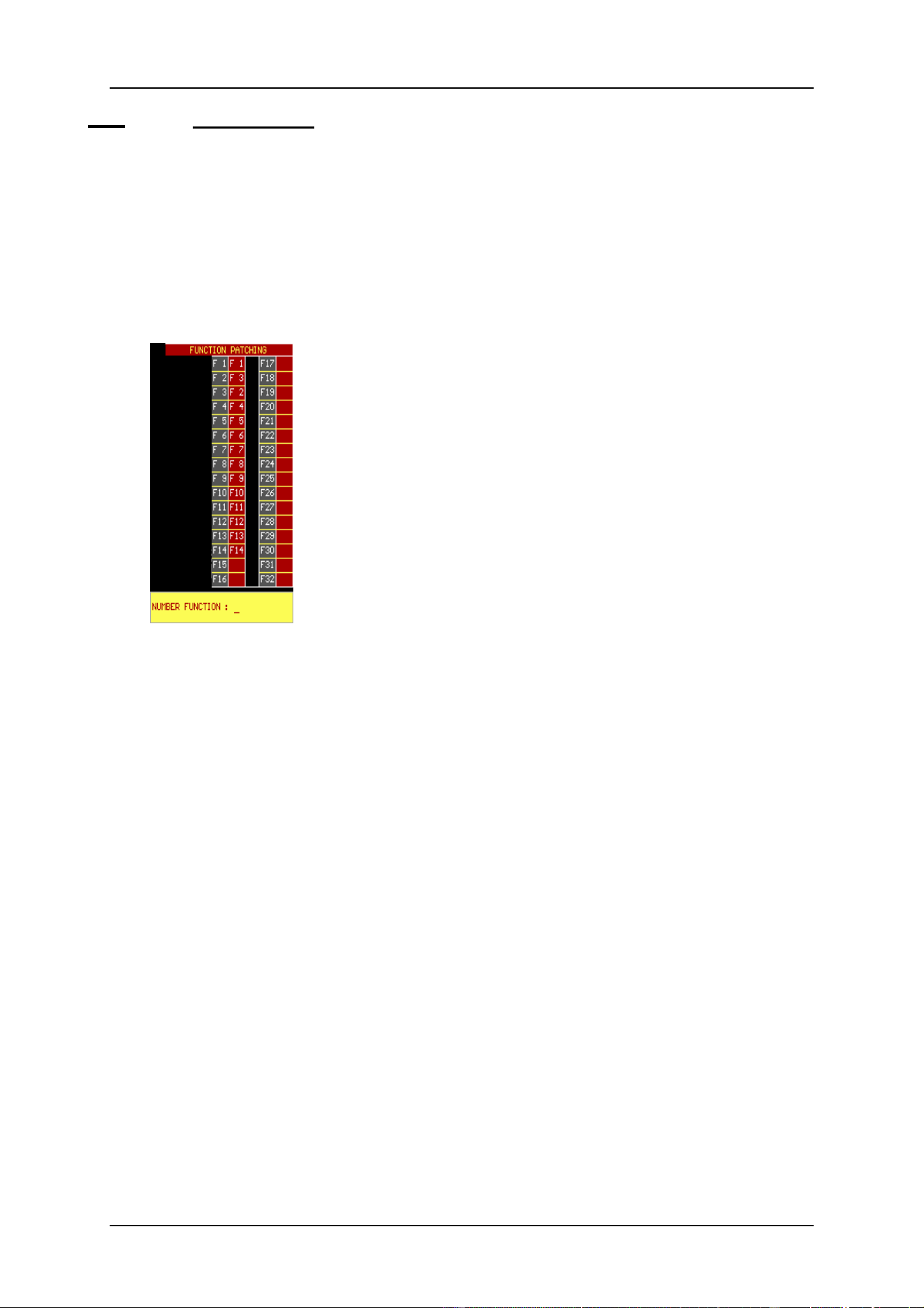
4.4.2 {EXP} Patch Function
Like fixtures, also the fixture channels can be re-patched, since every fixture type has
another channel ordering.
Ex.: For all types, channel 1 has to be dimmer, channel 2 has to be color and channel 3
gobo.
First, select a fixture from the library. The function patch window shows it’s patching:
This picture represents the function patch for a MAC600 in
Mode 4.
In this example, channel 2 (dimmer) is re-patched to channel 3
(CYAN) (F2 = F3 (cyan)), and channel 3 becomes the dimmer
channel (F3=F2 (dimmer)). Channel 1 remains the same (F1 =
F1).
If we want channel 2 to become the dimmer again and channel 3
to become cyan again then select:
Patch Function, give the number of the channel to re-patch
(ex. 2 [RET]), followed by the channel number where it should
be re-patched to (ex. 2 [RET]. In this case, channel 2 is re-
patched to its original state (F2 = F2). The same sequence has to
be repeated for channel 3 ([3] [RET] [3] [RET])
Rem. 1: It is impossible to re-patch 2 channels to the same function. The re-patch of
the channels has to be completely finished, or an error message will appear
(the red area cannot contain 2 times the same patch channel).
Rem. 2: It is also impossible to assign a patch number greater than the
maximum number of channels of the fixture. This means that the empty
boxes cannot be used.
04/2000 Martin Case Manual Version 7.20 Setup
R&D International NV for Martin Professional AS
32
4.4.3 {EXP} Patch link
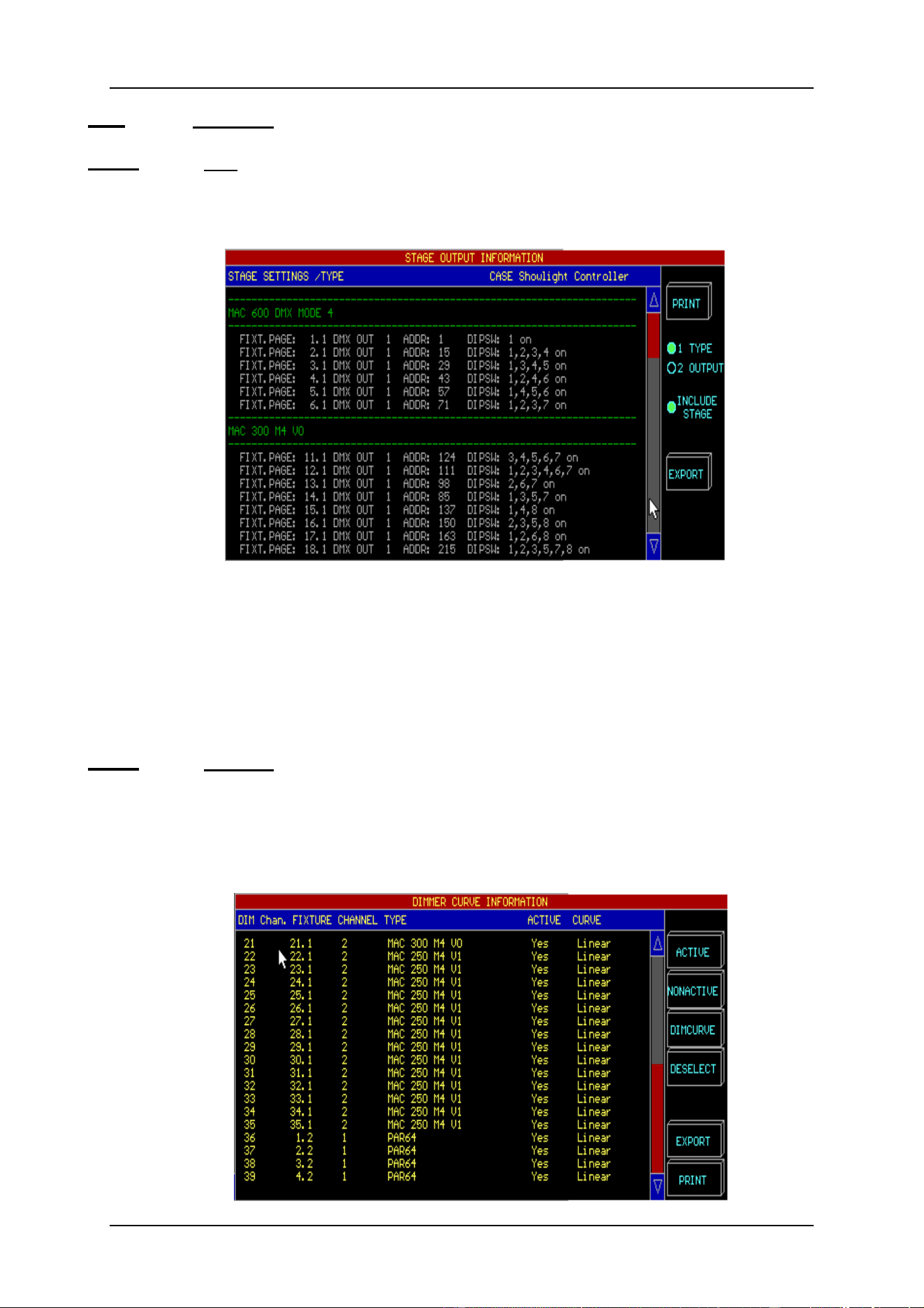
4.4.1.1 {EXP} Info
This function gives an overview of the already patched fixtures together with their
addresses, protocols and dipswitch settings. This info may be printed (in hp laserjet mode)
or exported.
There are 2 possible ways to group the information: by fixture type (type) or by controller
output (output).
When exporting, the stage layout can be added to the export file (include stage).
When the (export) function has been selected, the exported BMP file has to be copied to a
floppy disk using the MENU item (TO/FROM FLOPPY) (see chapter menu). This file can
be imported and printed on a Windows PC.
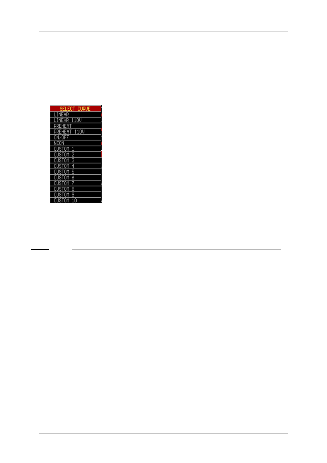
4.4.1.1 {EXP} Dimmer
Dimmer channels can be used with some advanced functions. Dimmer curves can be
assigned to them and the dimmer channels can be added to a list of dimmer channels where
special dimmer commands can be applied on. Those special commands are for example
DIMCHANNEL x THRU y @ zz%
Each dimmer channel can be configured separately.
04/2000 Martin Case Manual Version 7.20 Setup
R&D International NV for Martin Professional AS
33
In the above example, dimmer channel 35 represents the dimmer of a MAC250. It is
activated, which means that it is included in the list where the special dimmer commands
can be applied on. The channel has a linear dimmer curve.
Channel 36 is also included in the list and linear. Because channel 36 represents a PAR64,
we can assign another curve like PRE-HEAT to it.
To activate dimmer channels in the list, the fixture(s) have to be selected with the
trackerball and the ACTIVE or NONACTIVE box has to be clicked.
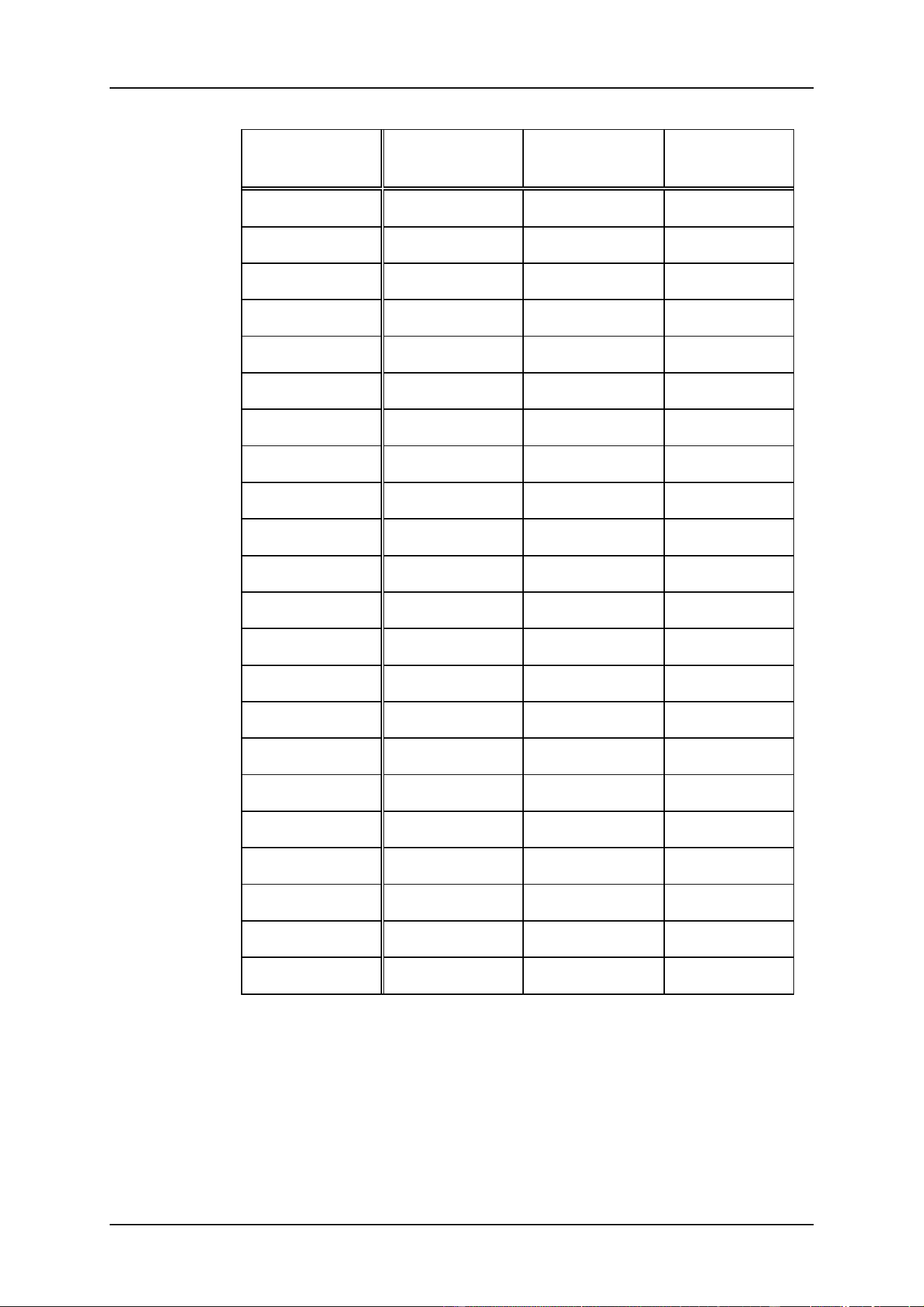
When the item DIMCURVE is selected, a supplementary window will open:
.
Linear: Normal linear curve
Linear 110V: Linear curve limited to 50% max value
Preheat: Linear curve starting from 5%
Preheat 110V: Preheat curve limited to 50% max value
ON/OFF: Relays function
Neon: Curve special for neon lamps
Custom x: User curves to be made with the program ‘Logicurve’
Note: the program ‘Logicurve’ is a Windows based program that can be downloaded from
the net for free. (addresses: see chapter Introduction). The user curves have to be imported
to the controller using the menu.
4.4.1.2 {EXP} Master (linking controllers, function has to be used on the MASTER desk)
MartinCase controllers are linked through DMX. This way, up to 41 controllers (with
playback info) and up to 113 controllers (without playback info) can be linked. To
accomplish this, the DMX output of the master controller is connected with the DMX
input of the slaves.
To set up a link, a fixture called ‘Case slave controller’ (out of the Casefixtures library)
with its DMX address, has to be placed on the stage
There are 3 possible fixture choices:
6 Case slave console: this is a slave controller without point cues and limited to 10
playbacks. New shows shouldn’t use this fixture anymore, it is only included
in the library to insure compatibility with older shows. New shows should
select the Case Slave Desk V2.
6 Case slave desk V2: this is a slave controller with point cues and 10 playbacks.
6 Case slave wing: Together with Case slave desk V2, a Pro Plus controller can be
linked.

04/2000 Martin Case Manual Version 7.20 Setup
R&D International NV for Martin Professional AS
34
After setting up the Case slave desk, the function Patch Link -- Master has to be selected.
One has to make the choice between Playbacks, Masters and Cues automatic or manual:
- Automatic: Playbacks, Master faders or cues will be send immediately to the
slave desks as soon as there is a change in one of them on the master.
The playbacks and master faders will have the same value on the
save desks and the same cues will be activated. In this case, you
don’t have to worry about the slave desks placed on the stage; they
are only there for the DMX addressing.
- Manual: The slave devices on the stage act as normal fixtures. Master faders
and playbacks have to be controlled as if they were normal fixtures.
The cues will only be activated on the slave desks when Case Slave
Desk channel 17 has a value higher than 50%. The advantage is that
different cues numbers and different master and playback fader
values and can be activated on the slaves.
On the slave desk, patch link SLAVE must be activated (see next paragraph).
4.4.1.3 {EXP} Slave (linking controllers, function has to be used on the SLAVE desk)
When controllers are linked, the function Patch Link – SLAVE has to be activated on
each slave desk to assign a DMX address to the slave controller.
When the function is selected, the DMX address of the Playbacks – master – cue will be
asked. This has to be the same address as assigned on the master desk for the ‘Case Slave
Desk V2’.
When there is also a ‘Case slave wing’ set up on the master, the address of the Playbacks
11 –42 on the slave should correspond with the ‘Case slave Wing’ address assigned on the
master. When there is no slave wing set up on the master, just press [RET] on the
Playbacks 11-42 item of the slave desk.
De controller will ask now if the master is working in %proportional or digital mode. In
case of a MartinCase controller, select the digital option, in case of an other brand master
controller, you have a choice.
Note: It is possible to control a MartinCase desk from an other brand controller using
DMX. The other brand controller, which will act as master, needs a library called
‘Case slave desk V2’ and ‘Case Slave Wing’ (for the channel values, see next
page). It is also possible to control the MartinCase slaves with a dimmer on the
Master. A dimmer of:
o 20 channels for a MartinCase with point cues
o 32 channels in case of a MartinCase slave with playbackwing.
The MartinCase slave controllers act as a normal fixture on the master. If a library
is made for another brand controller, the channel assignment will be:
04/2000 Martin Case Manual Version 7.20 Setup
R&D International NV for Martin Professional AS
35
Channel
Without point
cues (*)
With point
cues
Playback-
wing
1
playback 1
playback 1
playback 11
2
playback 2
playback 2
playback 12
3
playback 3
playback 3
playback 13
4
playback 4
playback 4
playback 14
5
playback 5
playback 5
playback 15
6
playback 6
playback 6
playback 16
7
playback 7
playback 7
playback 17
8
playback 8
playback 8
playback 18
9
playback 9
playback 9
playback 19
10
playback 10
playback 10
playback 20
11
grandmaster
grandmaster
playback 21
12
flashmaster
flashmaster
playback 22
13
submaster1
submaster1
playback 23
14
submaster2
submaster2
playback 24
15
cuepage
cuepage
playback 25
16
cuenumber
cuenumber
playback 26
17
GO (**)
GO (**)
playback 27
18
pointcue
playback 28
19
not in use
playback 29
20
not in use
playback 30
....
playback 31
32
playback 32
(*) The Case slave desk without point cues should not be used any more
starting from software version 7.0. It only exists in the library to retain
compatibility with older shows.
(**) The GO function is used to activate the cue, set with channels 15 and
16. To activate the cue, the GO channel must have a value > 127 (>50%).

04/2000 Martin Case Manual Version 7.20 Setup
R&D International NV for Martin Professional AS
36
4.4.1.4 {EXP} DMX-IN
DMX coming from other controllers can be read using the [SHIFT] [READ OUTP.] keys
in the main program when the controllers are linked through DMX-IN.
It is also possible to mix the DMX of 2 controllers with the same setup when both are
connected through the DMX output, DMX input. The DMX-IN signal will be mixed with
the DMX-OUT signal on the HTP principle. This means that the highest channel value
will take over.
Ex.: Suppose we have 2 desks with the same setup. The 2 desks are connected DMX-
OUT (desk 1) to DMX-IN (desk 2). Suppose channel 30 of desk 2 has a value of 80
and the same channel on DMX-IN coming from desk 1 has a value 100. On desk 2
the DMX value sent out by its DMX out will be 100.
DMX in (100) > DMX out (80) ----> DMX out = 100
To activate this, the DMX-IN channels of the fixtures on the stage must be active. Using
the function Patch Link - DMX-IN, the DMX-IN patch can be toggled ON or OFF.
4.4.2 Change address
This function is used to change the address of already patched fixtures on the stage.
This function is also used to change the multipatch/softpatch of an already existing
setup.
Select the function, click the fixture and select a new address value.
4.4.3 {EXP} Change RGB lib
When CMY (RGB) fixtures are in use, the filter library can be chosen. In the main
program, the [RGB] key is used to call a color by its filter number.
The library selected here will be used for all CMY fixtures in the main program. There is a
choice between LEE, ROSCO, or GAM.
Select the function and select a library.
4.4.4 Erase fixture
To erase an already configured fixture, select this function and click on the fixtures to
remove.
4.4.5 Erase all
To clear the entire stage. If this function is used accidentally, the setup can be left without
saving.
4.4.6 Redraw
Redraw everything.
04/2000 Martin Case Manual Version 7.20 Setup
R&D International NV for Martin Professional AS
37
4.4.7 Exit
To leave and save the setup program, select the exit function. When leaving, there is a
choice between:
6 Save
6 Not save
6 Cancel
When fixtures, of a type already in use in the stage, are added on an existing programmed
show, the setup program will ask next question when leaving:
Fixture x (Page y) is new.
Select a fixture to copy from...
With keys [1...70] or by clicking with the trackerball, the fixture(s), to copy from, can be
selected. All memories, presets and all cues of the selected fixture(s) will be copied to the
new fixtures.
Tip: It is easy to make a standard show that can be used on every occasion, if always the
same type of fixtures are used. Just prepare the show with only 1 or 2 fixtures of
every type. Since you can copy memories, cues and presets from the programmed
fixtures when leaving the setup, it is easy to extend an already existing show.
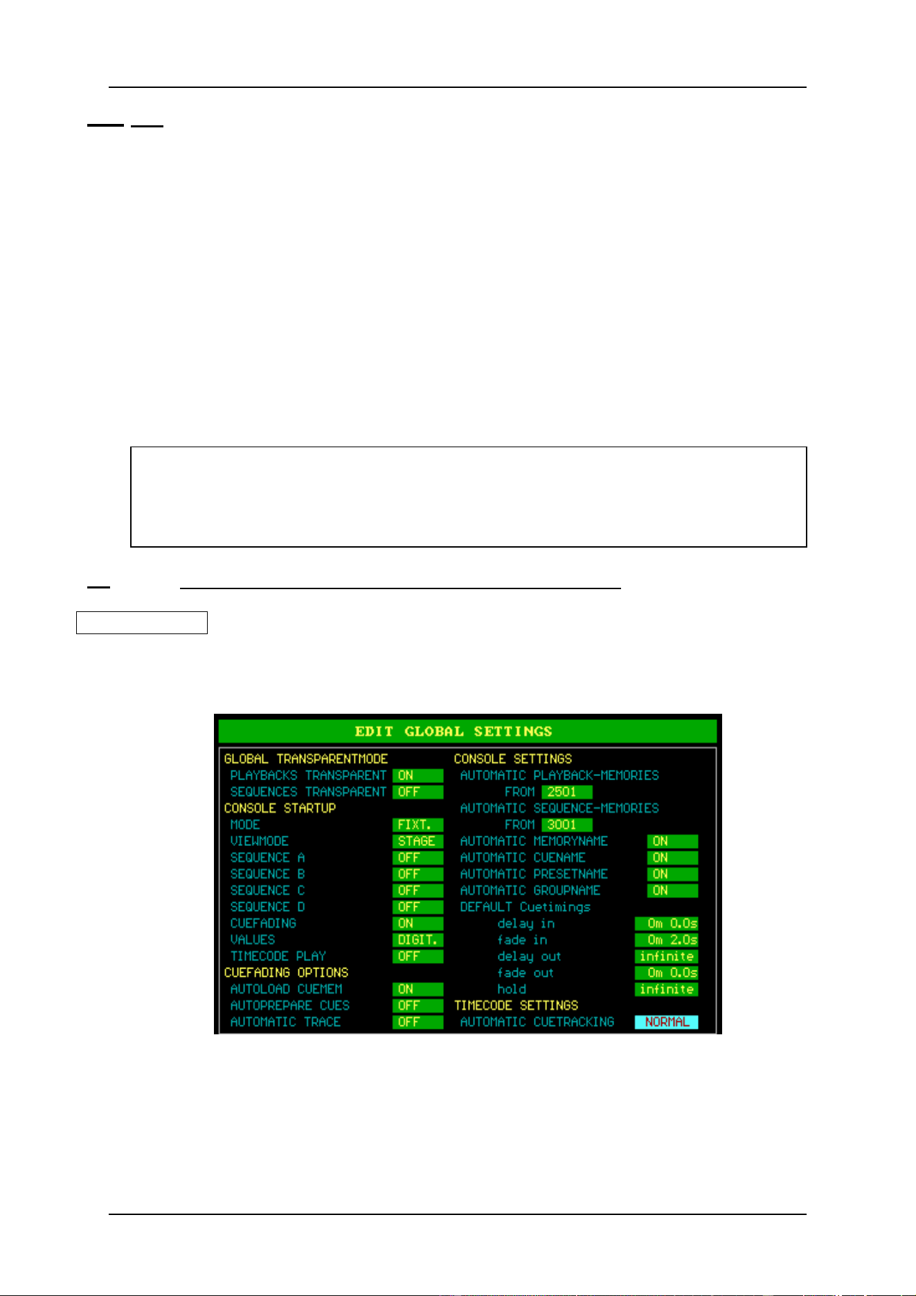
4.5 {EXP} Changing the start options and controller default values
[SETUP] [2]
When option [2] is selected from the main program when entering the SETUP, next menu
will appear:
The different options will become clear when reading the next chapters in this manual. We
will give here a brief description.
Note: The values in this example are the values from the ‘EMPTY’ show. Every time
a new show is started, those values will be applied to the show.

04/2000 Martin Case Manual Version 7.20 Setup
R&D International NV for Martin Professional AS
38
• Global Transparentmode
Sets the global transparent mode for the entire show. Possible choices for sequences
and playbacks are: OFF or ON. Explanation in chapter Sequences and Playbacks.
• Console Startup
The controller will activate those options when starting up:
MODE
Will start-up the controller in Fixture mode or cue mode.
VIEWMODE
Opens the STAGE, TEXT (names) or VALUES (channel values) screen when
starting up.
SEQUENCE A – D
Options: OFF or ON. Starts or stops the sequences when starting up. (Chapter
Sequences and Playbacks).
CUEFADING
Options: OFF or ON. Starts or stops the cuefading when starting up. (Chapter
Cuetimings).
VALUES
Options: DIGIT. or PERC. Shows the channel values in digital or proportional.
(Chapter Fixtures and Control channels).
TIMECODE PLAY
Options: OFF or ON. Starts or stops the time-code when starting up. Handy on
exhibitions, to automate everything when the power comes up. (Chapter Time-
code).
• Cue-fading Options
AUTOLOAD CUEMEMORY
Options: OFF or ON. Selects whether a cue-memory has to be loaded or not, in
the temporary memory, when selecting a cue. (Chapters cue-memories and cue-
timings).
AUTOPREPARE CUES
Options: OFF or ON. Selects whether the auto-prepare function is active or not.
(Chapter Cue-timings)
AUTOMATIC TRACE
Options: OFF or ON. Selects whether the automatic-trace function is active or
not. (Chapter Cue-timings)

04/2000 Martin Case Manual Version 7.20 Setup
R&D International NV for Martin Professional AS
39
• Console Settings
AUTOMATIC PLAYBACK-MEMORIES FROM
Sets the starting memory number from which memories will be created
automatically when using the fast playback-programming mode. (Chapter
Sequences and Playbacks).
AUTOMATIC SEQUENCE-MEMORIES FROM
Sets the starting memory number from which memories will be created
automatically when using the fast sequence-programming mode. (Chapter
Sequences and Playbacks).
AUTOMATIC MEMORYNAME
Options: OFF or ON. In ON mode, a memory name will be asked every time a
memory is created (also when using the fast programming mode of sequences and
playbacks). (Chapters Memories, Sequences and Playbacks).
AUTOMATIC CUENAME
Options: OFF or ON. In ON mode, a cue name will be asked every time a cue-
memory is created. (Chapters Cue-memories).
AUTOMATIC PRESETNAME
Options: OFF or ON. In ON mode, a preset name will be asked every time a
preset is created. (Chapter Presets).
DEFAULT CUETIMINGS
Assigns default timings, used when creating cue-memories. (Chapter cue-
timings).
• Time-code settings
AUTOMATIC CUETRACKING
Sets the time-code cue-tracking mode. (Chapter Time-code and Midi). Possible
choices are: Disabled, normal or full. This setting stipulates what should be done
with previous cues when the time code is started in the middle of a time-code
show.
[2
↓↓
] or [8
↑↑
] [EDIT]
To change the settings, highlight the item with the [2
↓
] or [8
↑
] keys and press the [EDIT]
key. When timing-values have to be given, use the keypad.
To save the settings, press the [RET] key.

04/2000 Martin Case Manual Version 7.20 Setup
R&D International NV for Martin Professional AS
40
4.6 Summary
Before programming starts, the stage setup has to be created.
To create it:
6 select a manufacturer
6 select a fixture type
6 select a fixture page with [Fixture PgDn], [Fixture PgUp] (up to 10 pages)
6 select the address and output
6 put the fixture somewhere in the stage window
6 rotate it to correspond the Pan/Tilt motions with the trackerball actions
6 repeat these steps until all fixtures are done
6 save the setup and return to the main program
Other functions:
6 drawing attributes to the stage and adapt the colors
6 re-patch fixtures
6 re-patch channels
6 select dimmer curves
6 linking of controllers
6 configure DMX-IN
6 RGB library select
6 print and export the stage and patch
The start options and default settings can be modified, and the auto-trace and auto-prepare
functions can be activated.
