

Z370RS Residential ZTrak 42A Deck
Serial Number 090001-
OPERATOR'S MANUAL
Z370RS Residential Zero Turn
Mowers
OMUC45088 ISSUE I5 (ENGLISH)
*OMUC45088*
CALIFORNIA
Proposition 65 Warning
Diesel engine exhaust and some of its constituents
are known to the State of California to cause cancer,
birth defects, and other reproductive harm.
If this product contains a gasoline engine:
WARNING
The engine exhaust from this product contains
chemicals known to the State of California to cause
cancer, birth defects or other reproductive harm.
The State of California requires the above two warnings.
John Deere Power Products
North American Edition
PRINTED IN U.S.A.
*DCY**omuc45088*

Foreword
THANK YOU for purchasing a John Deere product.
READ THIS MANUAL carefully to learn how to operate
and service your machine correctly. Failure to do so
could result in personal injury or equipment damage.
This manual and safety signs on your machine may also
be available in other languages. (See your John Deere
dealer to order.)
THIS MANUAL SHOULD BE CONSIDERED a
permanent part of your machine and should remain with
the machine when you sell it.
MEASUREMENTS in this manual are given in both
metric and customary U.S. unit equivalents. Use only
correct replacement parts and fasteners. Metric and
inch fasteners may require a specic metric or inch
wrench.
RIGHT-HAND AND LEFT-HAND sides are determined
by facing in the direction the machine or implement will
travel when going forward.
WRITE PRODUCT IDENTIFICATION NUMBERS (P.I.
N.) in the Specication or Identication Numbers
section. Accurately record all the numbers to help in
tracing the machine should it be stolen. Your dealer also
needs these numbers when you order parts. File the
identication numbers in a secure place o the machine.
WARRANTY is provided as part of John Deere's
support program for customers who operate and
maintain their equipment as described in this manual.
The warranty is explained on the warranty certicate or
statement which you should have received from your
dealer.
This warranty provides you the assurance that John
Deere will back its products where defects appear within
the warranty period. In some circumstances, John
Deere also provides eld improvements, often without
charge to the customer, even if the product is out of
warranty. Should the equipment be abused, or modied
to change its performance beyond the original factory
specications, the warranty will become void and eld
improvements may be denied. Setting fuel delivery
above specications or otherwise overpowering
machines will result in such action.
If you are not the original owner of this machine, it is in
your interest to contact your local John Deere dealer to
inform them of this unit's serial number. This will help
John Deere notify you of any issues or product
improvements.
DX,IFC5-19-03APR09
Required Emission-Related Information
Service Provider
A repair shop or person of the owner's choosing may maintain, replace, or repair emission control devices and systems with original or equivalent
replacement parts. However, warranty, recall, and all other services paid for by John Deere must be performed at an authorized John Deere
service center.
DX,EMISSIONS,REQINFO-19-08DEC23
Using Your Operator’s Manual
Read this operator’s manual, watch the safety video,
https://www.deere.com/en/parts-and-service/safety/
and review the safety signs on your machine before
use. They all contain important safety information and
operating instructions that must be followed to help
keep you and others safe. Be sure everyone who uses
the machine has read the manual, reviewed the safety
signs, and knows how to use the machine safely and
properly.
Your machine was designed and built to be operated in
accordance with all the safe operating instructions.
Since it was designed to cut grass, it can amputate
hands and feet and throw objects. If you do not follow
safety instructions, serious injury or death can occur.
This operator manual is organized in sections to help
you nd information quickly. You can use this manual to
nd answers to many of your operating and servicing
questions. An index at the end of this book helps you
nd needed information quickly. Contact your dealer if
this manual does not answer your questions.
Before using your machine:
● Know how to operate the machine. The Operating
Controls section helps you understand the controls of
your machine and what they do.
● Prepare your machine and the mowing area by
performing required daily checks outlined in the
General Instructions section.
● Follow instructions in the Preventing Injuries section,
especially related to:
- Keeping children safe by following instructions in
the Protect Children section.
- Avoiding injury on slopes and near terrain
hazards by following instructions in the Operating
on Slopes and Near Terrain Hazards section.
- Follow the instructions in the Avoid Thrown
Introduction

Objects section and keep all guards in place,
including discharge chute.
- Cleaning machine during use and before storing
as outlined in the Machine Cleanout section.
● Understand how to service and inspect your
machine.
If you do not understand the instructions or have
questions, contact your dealer.
The machine shown in this manual can dier slightly
from your machine.
RIGHT-HAND and LEFT-HAND sides are determined
by facing in the direction that the machine travels when
going forward. When you see a broken line (------), the
item referenced is hidden from view.
Before delivering this machine, your dealer performed a
predelivery inspection to ensure best performance.
This manual is an important part of your machine. Keep
this manual with the machine when you sell it.
gh8xt3t,1675916716358-19-08FEB23
Special Messages
Your manual contains special messages to bring
attention to potential safety concerns and machine
damage, as well as helpful operating and servicing
information. Please read all the information carefully to
avoid injury and machine damage.
CAUTION: Avoid injury! This symbol and text
highlight potential hazards or death to the
operator or bystanders that may occur if the
hazards or procedures are ignored.
IMPORTANT: Avoid damage! This text is used to tell
the operator of actions or conditions that might
result in damage to the machine.
NOTE: General information is given throughout the
manual that may help the operator in the operation
or service of the machine.
MX00654,000020D-19-04AUG25
Parts
We recommend John Deere quality parts and
lubricants, available at your John Deere dealer.
When you order parts, your John Deere dealer needs
the serial number or product identication number (PIN)
for your machine or attachment. These are the numbers
that you recorded in the Product Identication section of
this manual.
Order Service Parts Online
Visit https://partscatalog.deere.com/jdrc/ for your
Internet connection to parts ordering and information.
TC00531,00000E9-19-04AUG25
Service Literature
If you would like to purchase a copy of the Parts Catalog
or Technical Manual for this machine, visit The John
Deere Technical Information Store at:
https://techpubs.deere.com/
or call:
● U.S. & Canada: 1-800-522-7448.
● All Other Regions: Your John Deere dealer.
TH84124,0000199-19-04AUG25
Trademark
Trademarks
MulchControl™ Trademark of Deere & Company
Accel Deep™ Trademark of Deere & Company
ZTrak™ Trademark of Deere & Company
Ego Power+™ Trademark of Chervon
LoadMatch™ Trademark of Deere & Company
GVG6119,1748837174042-19-04JUN25
Introduction

Page
Product Identication
Record Identication Numbers . ........ . . . ........ . . 00-1
Register Your Product and Warranty Online . ...... 00-1
Safety Labels with Text
Safety Label Location . ......... . . ........ . . . .......... 05-1
Understanding the Machine Safety Labels . ........ 05-2
WARNING ...... . . ........ . . ........... . . ......... . . .... 05-2
DANGER .... ........... . . ......... . . ........... . . ...... 05-2
DANGER .... ........... . . ......... . . ........... . . ...... 05-2
WARNING ...... . . ........ . . ........... . . ......... . . .... 05-3
CAUTION ........ . . ........ . . . .......... . . ......... . . .. 05-3
DANGER .... ........... . . ......... . . ........... . . ...... 05-3
DANGER .... ........... . . ......... . . ........... . . ...... 05-3
Safety Labels without Text
Safety Label Location . ......... . . ........ . . . .......... 06-1
Understanding the Machine Safety Labels
without Text ......... . . ........... . . ......... . . ...... 06-2
Read Operator’s Manual . ......... . . ......... . . ...... 06-2
Keep Children Away from Mower .. . . ........... . . .. 06-2
Avoid Injury from Rotating Blades ............ . . .... 06-2
Avoid Injury From Thrown Objects ........ . . ........ 06-2
Avoid Serious Injury or Death from Tipping ........ 06-2
Avoid Injury from Pinch Point ..... . . ......... . . ...... 06-3
Safety
Use Your Mower Safely ............. . . ........... . . .. 10-1
Preventing Injuries .... . . ........... . . ......... . . ...... 10-1
Operating on Slopes and Near Terrain
Hazards .. . . . .......... . . ......... . . ......... . . ...... 10-2
Lithium Battery Fires ........... . . ........ . . . .......... 10-3
Electrical Safety .............. . . ........ . . ........... . . 10-3
Prevent Fires .. . . ........ . . ........... . . ......... . . .... 10-4
Parking Safely ... . . ........ . . . .......... . . ......... . . .. 10-4
Additional Safety Information ........... . . . ........ . . 10-5
Machine Cleanout
General Cleaning Guidelines ........... ........... . . 15-1
Cleanout Areas . . .......... ........... . . ......... . . .... 15-1
Operating Controls
Operator’s Station Controls ........... . . ......... . . .. 25-1
Instrument Cluster ...... . . ........... . . ......... . . .... 25-1
Battery Pack .................. . . .......... . . . ........ . . 25-2
Charger .... ........... . . ......... . . ........... . . ........ 25-3
Daily Operations
Daily Operating Checklist ............... . . . ........ . . 30-1
Avoid Damage to Plastic and Painted
Surfaces ........... . . ........... . . ......... . . ........ 30-1
Page
Use Power Button ........ . . . .......... ........... . . ... 30-1
Status Display ...... . . ........... . . ......... . . ........ . 30-1
Operate the Rear Cover . ......... . . ........... . . ..... 30-1
Mounting and Dismounting Machine ......... . . ..... 30-2
Adjust Seat ... . . . .......... . . . ........ . . ........... . . ... 30-2
Adjust Motion Control Levers . . ........... .......... . 30-2
Adjust Cutting Height ................. . . ......... . . ... 30-3
Adjust Mower Wheels . ........... . . ......... . . ....... 30-3
Adjust Mower Level ......... . . .......... ........... . . . 30-4
Test Safety Systems ... . . ........... . . ......... . . ..... 30-5
Test Park Brake Switch . . ......... . . ........... . . ..... 30-5
Test Park Brake ........ . . ......... .. ........... . . ..... 30-6
Test Mower Engagement (PTO) Switch ..... . . ..... 30-6
Test Seat Switch ... . . ......... . . ........ . . . .......... . 30-6
Use Park Brake ............... . . ........... . . ........ . 30-6
Using Mower Engagement Switch ............. . . ... 30-7
Use the Motion Control Levers ............. . . ....... 30-7
Start the Machine . . ........... . . ........ . . . .......... . 30-9
Engage Mower ........... . . . ........ . . ........... . . ... 30-9
Stop the Machine .. . . ......... . . ........... . . ........ . 30-9
Use MulchControl (If Equipped) . . . ........... . . ..... 30-9
Use Charging Port ..... ........... . . ......... . . ...... 30-10
Manually Moving Machine . .......... . . ......... . . .. 30-10
Unclog Mower ...... . . ......... . . ........... . . ........ 30-11
Unclog Mower, Bagger, or Material Collection
System . . ......... . . ........... . . ......... . . ........ 30-11
Use Wash Port to Clean Mower Deck ....... . . .... 30-11
Transport Machine on Trailer ............. . . ........ 30-12
Transporting Material Collection System (If
Equipped) .......... . . ......... . . ........... . . ...... 30-13
Tow Loads ........ . . ........... . . ........ . . . ........ . . 30-13
Mowing Tips .... . . ........... . . ........ . . ........... .. 30-13
Blade Choices .... . . ......... . . .......... . . . ........ . . 30-13
Standby Mode .... . . ......... . . .......... . . . ........ . . 30-13
Service Intervals
Servicing Machine ....... . . . .......... . . ......... . . ... 35-1
Service Intervals ........ ........... . . ......... . . ....... 35-1
Service Mower
Mower Deck Identication .... . . ........ . . . ........ . . . 55-1
Remove and Install Mower Deck Foot Plate .... . . . 55-1
Remove Mower Deck (42-IN) .. . . ......... . . ......... 55-1
Install Mower Deck (42-IN) . .......... . . ......... . . ... 55-2
Install MulchControl Discharge Plate (If
Equipped) .......... . . ......... . . ........... . . ....... 55-4
Install MulchControl Deector (If Equipped) ....... 55-4
Install MulchControl Handle (If Equipped) ........ . 55-5
Remove and Store MulchControl (If
Equipped) .......... . . ......... . . ........... . . ....... 55-5
Install Mulch Blades .............. . . ........... . . ..... 55-6
Checking for Bent Mower Blades ........ . . ......... 55-7
Continued on next page
Original Instructions. All information, illustrations and specications in this
manual are based on the latest information available at the time of publication.
The right is reserved to make changes at any time without notice.
COPYRIGHT © 2025
DEERE & COMPANY
Moline, Illinois
All rights reserved.
Previous Editions
Copyright © 2024
Contents
i

Page
Service Mower Blades ....... . . ........ . . ........... . . 55-7
Service Electrical
Battery ... . . ......... . . ......... . . .......... . . . ........ . . 60-1
Decommissioning — Proper Recycling and
Disposal of Fluids and Components . . . .......... 60-1
Lithium-Ion Batteries - No Serviceable Parts ...... 60-2
Service Miscellaneous
Lift Machine .... . . .......... . . . ........ . . ........... . . .. 65-1
Checking Tire Pressure ............... . . ......... . . .. 65-1
Remove and Install Wheel Assembly ........... .... 65-1
Remove and Install Front Caster Wheels . . ........ 65-2
Cleaning and Repairing Metal Surfaces .. . . ........ 65-3
Troubleshooting
Icons and Denitions ........ . . ........ . . ........... . . 70-1
Using Troubleshoot Chart . . . ........ . . ........... . . .. 70-3
Battery—Troubleshooting ... . . .......... . . . ........ . . 70-3
Charger—Troubleshooting ...... . . ........... . . ...... 70-4
Electrical . . . ........... . . ......... . . ........ . . . .......... 70-4
Machine . ......... . . ........... . . ........ . . ........... . . 70-4
Mower Deck ......... . . ........... . . ......... . . ........ 70-5
MulchControl (If Equipped) .. . . ........ . . ......... . . .. 70-5
PTO Switch . . . . .......... ........... . . ......... . . ...... 70-6
Fault Table (E-Codes) .... ........... . . ......... . . .... 70-6
Storage
Preparing Machine for Storage ....... . . ......... . . .. 75-1
Optimize Battery ....... ........... . . ......... . . ........ 75-1
Removing Machine from Storage ......... . . ........ 75-1
Lithium-Ion Battery Handling and Storage ....... . . 75-1
Specications
Full Travel Speed ......... . . . ........ . . ......... . . .... 80-1
Charger .... ........... . . ......... . . ........... . . ........ 80-1
Electrical System ........ ........... . . ......... . . ...... 80-1
Ambient Temperature Operation ............ . . ...... 80-1
Minimum Gauge for Charging Cord ....... . . ........ 80-1
Tires ............ . . ........ . . ........... . . ......... . . .... 80-1
Dimensions ........ . . ......... . . ........ . . ........... . . 80-1
Mower Decks ........ . . ......... . . ........... . . ........ 80-2
Warranty
Product Warranty . . ........ . . . .......... ........... . . .. 85-1
Tire Warranty ...... . . ........... . . ........ . . . ........ . . 85-1
Limited Battery Warranty For Factory
Installed Batteries ...... ........... . . ......... . . .... 85-1
End User License Agreement
Bluetooth Connectivity (If Equipped) ........ . . ...... 82-1
John Deere Quality Statement
John Deere Quality ....... . . . .......... . . ......... JDQS-1
Slope Gauge
Slope Gauge Template ........ . . ........... . . ....... SG-1
Contents
ii

Record Identication Numbers
Zero-Turn Mowers
When you contact an Authorized Service Center for
information on servicing, always provide the product
model and identication numbers.
Locate the model and serial number for the machine,
battery of your machine and record the information in
the spaces provided as follows.
DATE OF PURCHASE:
_________________________________________
DEALER NAME:
_________________________________________
DEALER PHONE:
_________________________________________
Product Identication Number:
__ __ __ __ __ __ __ __ __ __ __ __ __ __ __ __ __
APY551603—UN—15FEB23
A—Product Identication Number
Charger Identication Number:
__ __ __ __ __ __ __ __ __ __ __ __ __ __ __ __ __
GX669593—UN—09JUL25
C—Charger Identication Number
Battery Pack Identication Number:
__ __ __ __ __ __ __ __ __ __ __ __ __ __ __ __ __
__ __ __ __ __ __ __ __ __ __ __ __ __ __ __ __ __
__ __ __ __ __ __ __ __ __ __ __ __ __ __ __ __ __
__ __ __ __ __ __ __ __ __ __ __ __ __ __ __ __ __
__ __ __ __ __ __ __ __ __ __ __ __ __ __ __ __ __
__ __ __ __ __ __ __ __ __ __ __ __ __ __ __ __ __
GX669592—UN—27MAY25
B—Battery Pack Identication Number
GVG6119,1748319720206-19-07JUL25
Register Your Product and Warranty Online
To register your product through the Internet, simply go
to www.JohnDeereWarrantyRegistration.com.
Completing the information, either online or with the
Product Identication
00-1

product warranty card, will ensure that your product will
receive all post sales, service, and important product
information.
MP47322,00F45FF-19-17MAY22
Product Identication
00-2

Safety Label Location
GX669590—UN—10JUN25
Z370R Electric Model Shown
A—WARNING M146577
B—DANGER UC36931
C—DANGER, WARNING, CAUTION UC45451
D—DANGER M139128
E—DANGER UC36935
SDHTXN6,1746611019541-19-04JUN25
Safety Labels with Text
05-1

Understanding the Machine Safety Labels
MXAL42363—UN—22MAY13
The machine safety labels shown in this section are
placed in important areas on your machine to draw
attention to potential safety hazards. DANGER or
WARNING safety labels are located near specic
hazards.
The operator’s manual also explains any potential
safety hazards whenever necessary in special safety
messages that are identied with the word, CAUTION,
and the safety-alert symbol.
On your machine safety labels, the words DANGER,
WARNING, and CAUTION are used with this safety-
alert symbol. DANGER identies the most serious
hazards:
● DANGER; The signal word DANGER indicates a
hazardous situation which, if not avoided, will result
in death or serious injury.
● WARNING; The signal word WARNING indicates a
hazardous situation which, if not avoided, could
result in death or serious injury.
● CAUTION; The signal word CAUTION indicates a
hazardous situation which, if not avoided, could
result in minor or moderate injury. CAUTION may
also be used to alert against unsafe practices
associated with events which could lead to personal
injury.
Replace missing or damaged safety labels. Use this
operator’s manual for correct safety label placement.
There can be more safety information contained on
parts and components sourced from suppliers that is not
reproduced in this operator’s manual.
Spanish Safety Labels and Operator’s Manual
Operator’s manuals and safety labels with content in
Spanish are available for this machine through
authorized John Deere dealers. See your John Deere
dealer.
gh8xt3t,1675785974146-19-21MAR23
WARNING
APY564709—UN—09FEB23
To avoid injury from loaded spring, read operator’s
manual before changing attachments.
gh8xt3t,1675924315143-19-20FEB23
DANGER
APY564710—UN—09FEB23
ROTATING BLADE
Do not put hands or feet under or into mower when
machine is running.
gh8xt3t,1675765493295-19-24MAR23
DANGER
APY571651—UN—23MAR23
ROTATING BLADES CUT OFF ARMS AND LEGS
● Do not mow when children or bystanders are around.
● Do not mow in reverse unless necessary.
● Look down and behind before backing up.
● Look in the direction of travel.
● Never carry children on the machine, even with the
blades o.
SDHTXN6,1746607525735-19-07MAY25
Safety Labels with Text
05-2
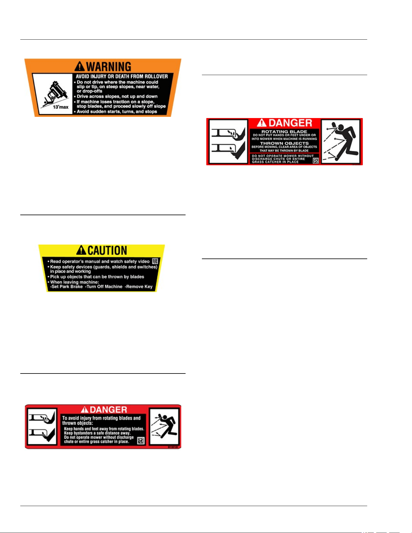
WARNING
GX663354—UN—08MAY25
AVOID INJURY OR DEATH FROM ROLLOVER
● Do not drive where the machine could slip or tip: on
steep slopes, near water, or near drop-os.
● Never mow or operate the machine on slope angles
greater than 13°.
● Drive across slopes, instead of up and down.
● If the machine loses traction on a slope, stop the
blades and proceed slowly o the slope.
● Avoid sudden starts, turns, or stops.
SDHTXN6,1746607535877-19-12JUN25
CAUTION
APY571653—UN—21MAR23
● Read the operator's manual and watch the safety
video.
● Keep safety devices (guards, shields, and switches)
in place and working.
● Pick up objects that can be thrown by the blades.
● When leaving machine, do the following:
- Set Park Brake - Turn o Machine -Remove Key.
SDHTXN6,1746607582773-19-07MAY25
DANGER
APY564711—UN—20FEB23
To avoid injury from rotating blades and thrown objects:
● Keep hands and feet away from rotating blades.
● Keep bystanders a safe distance away.
● Do not operate mower without discharge chute or
entire grass catcher in place.
gh8xt3t,1675931325571-19-24MAR23
DANGER
APY564712—UN—20FEB23
ROTATING BLADE
DO NOT PUT HANDS OR FEET UNDER OR INTO
MOWER WHEN MACHINE IS RUNNING.
THROWN OBJECTS
BEFORE MOWING, CLEAR AREA OF OBJECTS
THAT MAY BE THROWN BY BLADE.
DO NOT OPERATE MOWER WITHOUT DISCHARGE
CHUTE OR ENTIRE GRASS CATCHER IN PLACE.
gh8xt3t,1675765599622-19-24MAR23
Safety Labels with Text
05-3

Safety Label Location
GX669591—UN—10JUN25
Z380R Electric Model Shown
A—WARNING - M146611
B—DANGER - M118041
C—DANGER, WARNING, CAUTION - UC45452
D—DANGER - M138631
E—DANGER - M173018
SDHTXN6,1746611619838-19-04JUN25
Safety Labels without Text
06-1
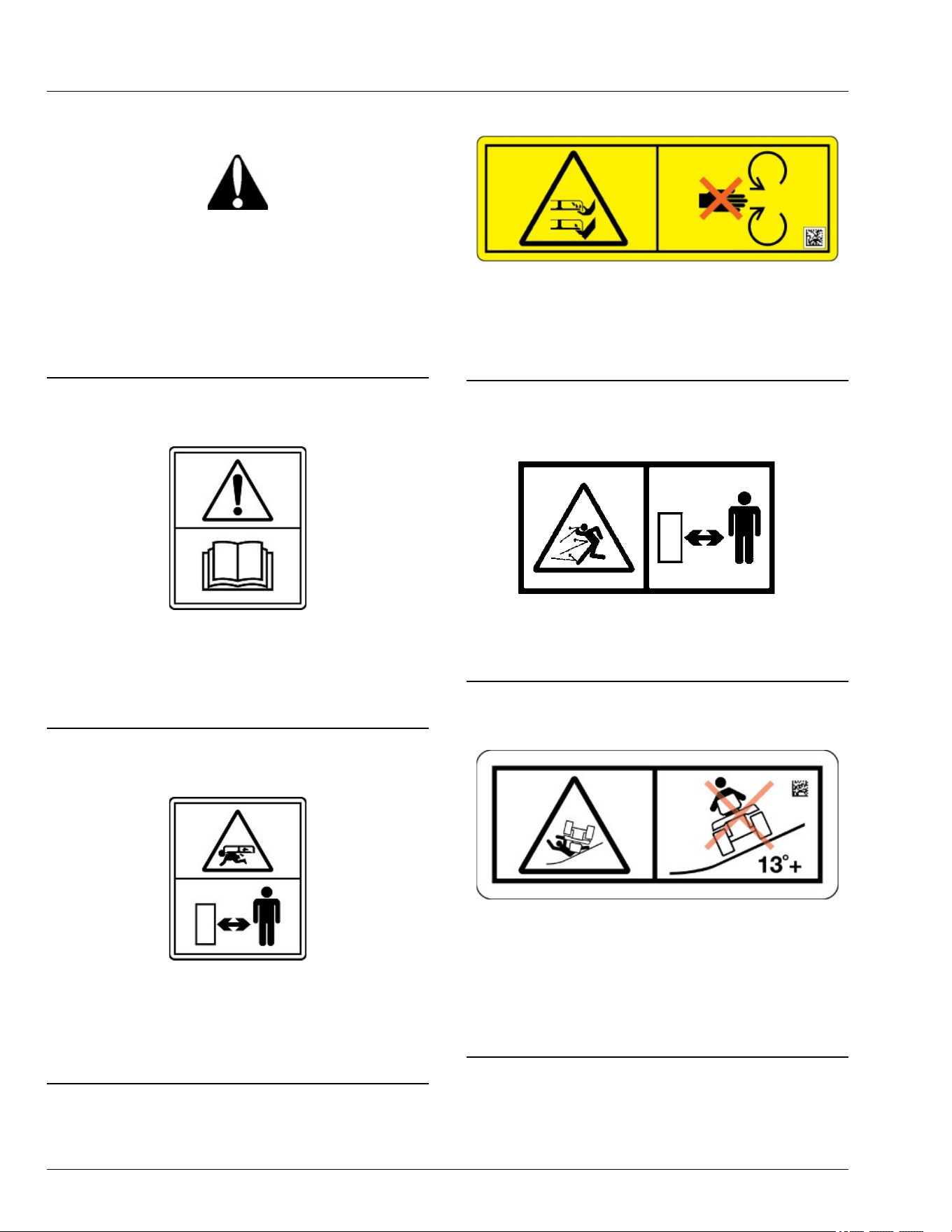
Understanding the Machine Safety Labels
without Text
TCT005498—UN—11SEP12
The machine safety labels shown in this section are
placed in important areas on your machine to draw
attention to potential safety hazards.
On your machine safety labels, the words DANGER,
WARNING, and CAUTION are used with this safety-
alert symbol. DANGER identies the most serious
hazards.
MX00654,0000389-19-09JAN23
Read Operator’s Manual
MXT013479—UN—05MAR15
● This operator’s manual contains important
information necessary for safe machine operation.
● Carefully read operator’s manual before operating
machine. Observe all safety rules to avoid accidents.
TH84124,0000173-19-12JUN15
Keep Children Away from Mower
MXT013480—UN—05MAR15
● Mower can cause dismemberment or death.
● Stay a safe distance from the machine.
● Make sure that children stay clear of mower at all
times when the machine is running.
gh8xt3t,1715074523480-19-07MAY24
Avoid Injury from Rotating Blades
TC1362285—UN—28MAR24
● Do not put hands or feet under or into mower when
machine is running.
● Do not operate mower without discharge chute/
deector or entire grass catcher in place.
gh8xt3t,1715074481750-19-07MAY24
Avoid Injury From Thrown Objects
MXAL42780—UN—09APR13
Keep a safe distance from the machine as long as the
machine is running.
gh8xt3t,1715074393527-19-07MAY24
Avoid Serious Injury or Death from Tipping
GX669619—UN—02JUN25
● Do not drive where the machine could slip, tip, or roll
over.
● Never mow or operate the machine on slope angles
greater than 13 degrees.
● Refer to the "Operating on Slopes" section for more
information.
SDHTXN6,1745840798584-19-10JUN25
Safety Labels without Text
06-2

Avoid Injury from Pinch Point
MXAL42777—UN—09APR13
● Keep ngers and hands away from pinch point.
● Read operator’s manual.
gh8xt3t,1712224127603-19-05APR24
Safety Labels without Text
06-3

Use Your Mower Safely
General Instructions
● Read this operator’s manual, watch the safety video,
and review the safety signs on your machine before
use. They all contain important safety information
and operating instructions that must be followed to
help keep you and others safe. Be sure everyone
who uses the machine has read the manual,
reviewed the safety signs, and knows how to use the
machine safely and properly.
● Age, physical ability, and mental capacity can be
factors in equipment-related injuries. Operators must
be mentally and physically capable of operating the
machine properly and safely. Never allow a child to
operate the machine.
● Do not operate the machine while under the
inuence of alcohol or drugs or when distracted or
fatigued. Proper operation requires your full
attention.
● Always wear eye protection, hearing protection,
close-tting clothing, and substantial footwear while
operating the machine. Never operate while wearing
sandals or when barefoot.
● Do not wear radio or music headphones. Both safe
operation and service require your full attention.
● Never tamper with safety devices.
● Operate the machine only in daylight or good articial
light.
● Look both ways when approaching roadways and
use caution when turning around on public
roadways. You can be struck by a vehicle and suer
serious injury or death.
● Never mow when there is a risk of lightning.
Before Using Your Machine
● Know how to operate the machine. The Operating
Controls section helps you understand the controls of
your machine and what they do.
● Prepare your machine and the mowing area by
performing required daily checks outlined in the
General Instructions section.
● Follow instructions in the Preventing Injuries section,
especially related to:
- Keeping children safe by following instructions in
the Protect Children section.
- Avoiding injury on slopes and near terrain
hazards by following instructions in the Operating
on Slopes and Near Terrain Hazards section.
- Follow the instructions in the Avoid Thrown
Objects section, and keep all guards in place,
including discharge chute.
- Cleaning machine during use and before storing
as outlined in the Machine Cleanout section.
● Understand how to service and inspect your
machine.
● Disconnect the machine from charging.
Inspection and Daily Checklist
● Inspect machine before you operate. Be sure that
hardware is tight, and all guards and shields are in
good condition and fastened in place. Make all
necessary adjustments before you operate. Repair or
replace damaged, badly worn, or missing parts.
● Visually inspect that mower blades, blade bolts, and
the mower assembly are not worn or damaged. To
prevent machine damage, replace worn or damaged
blades and bolts in sets.
● If the machine is emitting heat or unusual smells, do
not operate it. Move the machine 50 ft (15 m) away
from buildings and combustible material, and contact
your service provider.
Check the Mowing Area
● Keep bystanders and pets out of the mowing area.
● Clear the area of objects such as rocks, wire, or toys,
which can be thrown by the blades. Remove low-
hanging branches or other obstacles, which can
interfere with your travel path.
● Study the mowing area. Set up a safe mowing path.
Do not mow where traction or stability is doubtful.
● Slopes and terrain hazards are major factors related
to loss-of-control and tipover accidents. Operation on
slopes and near terrain hazards requires extra
caution. Follow instructions in the Operating on
Slopes and Near Terrain Hazards section.
Weights and Attachments
● Some attachments require ballast weights. Follow
recommendations for wheel weights or
counterweights.
● Use only accessories and attachments approved by
John Deere.
● If you do not understand the instructions or have
questions, contact your service provider.
SDHTXN6,1746612961665-19-16JUL25
Preventing Injuries
Protect Children
MXT005340—UN—06JUN13
● Children can be killed or seriously injured by riding
mowers when operators do not follow safe operating
practices.
● Do not mow in reverse. Operating with the mower
engaged while backing up is discouraged.
Safety
10-1
● Never give children a ride on a mower or in a cart
behind the mower, even when the blades are o.
They can fall o and be run over or cut by the mower
blades. Children can interfere with mower operation.
Children who have been given rides in the past can
suddenly appear in the mowing area for another ride.
If you are not aware, they can be run over or backed
over by the mower.
● Children are often attracted to lawn mowers and
mowing activities, especially if they have been given
rides before. They do not know if the blades are
rotating or understand that they can be killed or
seriously injured even if the blades are not rotating.
● Keep children indoors and out of the mowing area
when the mower is being operated. Keep children
under the watchful eye of a responsible adult, other
than the operator. If there is not a responsible adult to
ensure that children stay indoors, DO NOT mow.
● Be alert to the presence of children or others. Turn o
the mower blades and stop the machine if someone
enters the mowing area.
● Look in the direction the machine is traveling. Before
and while backing, turn o the mower blades and
look down and behind the machine carefully,
especially for children.
● Use extreme care when approaching objects that
block your view, such as blind corners, shrubs, or
trees, especially while backing. They can hide a
child.
Avoid Thrown Objects
● Clear the mowing area of all bystanders when using
this machine. Thrown objects could cause serious
injury or death.
● Clear the area of objects such as rocks, wire, or toys,
which can be thrown by the blades.
● Never direct discharged material toward anyone.
● Avoid discharging material against a wall or
obstruction such as a fence or retaining wall. Material
can ricochet towards the operator.
● Avoid discharging material towards a street or
roadway.
● Stop the blades when crossing gravel surfaces.
OUO2005,000078C-19-15FEB20
Operating on Slopes and Near Terrain
Hazards
● Slopes are a major factor related to loss of control
and tip-over accidents, which can result in serious
injury or death. Use caution and common sense
when operating on slopes.
● If you feel uneasy on a slope, do not mow or operate
the machine on it.
● Drive up and down slopes, not across them.
● Watch for holes, ruts, bumps, rocks, or other hidden
objects. Tall grass can hide obstacles.
● Drive slowly so you do not have to stop while on a
slope.
● Do not mow on wet grass. Tires can slip on wet grass
even if the brakes are working normally.
● Keep all movement on slopes slow and gradual. Do
not make sudden changes in speed or direction,
which can cause the ride-on mower to roll over.
● If the tires lose traction, disengage the PTO and
proceed slowly and carefully o the slope.
● Do not shift to neutral and coast downhill.
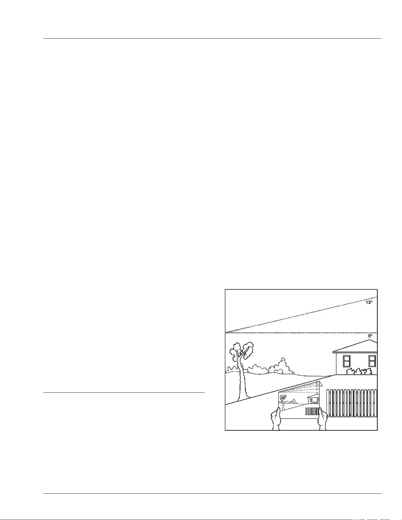
Identify Safe Slopes
● Before using your machine, measure the slopes of all
mowing areas to determine which slopes are safe for
mowing with a ride-on mower. Use good judgment
and common sense when performing this survey.
Measuring Slopes
● Suggested method 1: Lay a straight piece of sturdy
lumber 1.2 m (4 ft) long on the slope and measure
the angle with an angle gauge or protractor level.
● Suggested method 2: Refer to the slope gauge
provided at the end of the manual.
Slope Limits
● Exceeding the recommended maximum slope angle
increases the risk of rollover accidents that can result
in serious injury or death.
GX100108—UN—14FEB20
● Never mow or operate this ride-on mower on slope
angles greater than 13°. (A 13° slope is a slope that
rises 1.4 m [4.6 ft] over a horizontal distance of 6.1 m
[20 ft].)
● Material collection systems, weather enclosures, or
other attachments increase the risk of a rollover.
Safety
10-2
● As slope increases the risk of rollover increases.
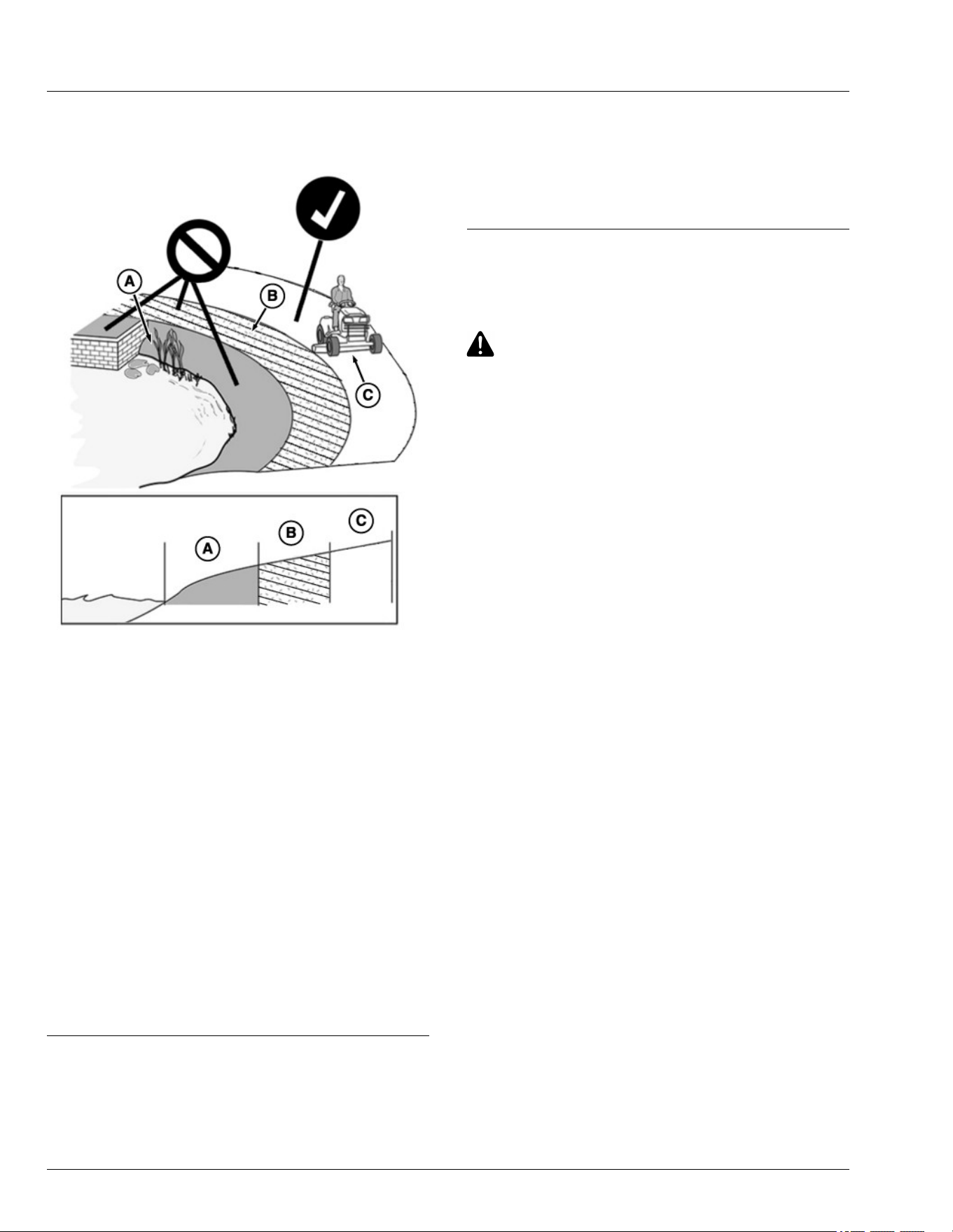
Operating Near Terrain Hazards
GX100106—UN—01FEB20
● Terrain hazards such as ditches and drop-os are a
factor related to loss of control and tip-over
accidents, which can result in serious injury or death.
Use caution and common sense when operating
near terrain hazards.
● Do not mow or operate the machine in areas
adjacent to hazards that can cause the machine to
roll over. If a wheel goes over an edge or if the edge
breaks away, the machine can suddenly lose
traction, slide, and/or roll over.
● Hazards (A) include but are not limited to ditches,
drop-os, embankments, or areas near bodies of
water.
● Maintain a buer area (B) at least as wide as the
machine between hazards (A) and the mowing area
(C). Do not mow or operate the machine in the
hazard area or buer area.
● Only mow or operate in the mowing area (C). Do not
exceed the recommended slope operating angle.
Refer to the Slope Limits section.
SDHTXN6,1745840980137-19-04JUN25
Lithium Battery Fires
● Do not attempt to extinguish a Lithium battery re.
● Handheld extinguishers and or residential water
supplies will not be sucient to extinguish a Lithium
battery re.
● If a Lithium battery re is suspected, maintain a safe
distance from the machine and call rst responders
immediately.
gh8xt3t,1679482823353-19-24MAR23
Electrical Safety
General Electrical Safety
CAUTION: Avoid Injury! Failure to follow all
instructions listed below may result in electric
shock, re and/or serious injury.
1. Remove key pin before inspecting, cleaning, or
servicing machine.
2. Before each use, inspect machine for damaged
electrical components.
3. Unplug charging cord from machine before moving
machine, prior to cleaning, maintenance, or service.
4. Service machine only as indicated in the service
instructions. Contact your servicing provider for
assistance with service or replacement of any
electrical components.
Charging Your Battery Safely
1. Inspect machine, for exposed electrical components
and harnesses for damage before each use. If
damage is found, move machine away from buildings
and combustible material until repairs can be made.
2. Do not use multiple extension cords.
3. Do not charge machine in standing water or in the
rain.
4. Disconnect charger from vehicle, before moving
machine, prior to cleaning, maintenance, or service.
5. Inspect charging cord for damage before each use.
Do not use if cord is damaged.
6. Only plug charging cord into a grounded outlet. Use a
ground fault circuit interrupter (GFCI) or residual
current device (RCD) protected supply. Use of a
GFCI reduces the risk of electric shock. Do not
modify plug or use adapter plugs.
7. Handle charging cord with care. Keep cord away
from heat, oil, and sharp edges. Damaged or
entangled cords increase the risk of electric shock.
8. When charging outdoors, use charging cord suitable
for outdoor use. Use of a cord suitable for outdoor
use reduces the risk of electric shock.
9. (See specications section: Minimum Gauge for
Charging Cord).
Safety
10-3

Use Caution Wet Conditions
CAUTION: Avoid injury! Contacting charging
cord in wet conditions will increase the risk of
electric shock.
1. Do not handle the charging cord with wet hands,
while standing in water, or in the rain. Do not route
cord through standing water or wet grass.
2. Do not use, store, transport, or charge the machine in
wet conditions.
3. Do not clean machine by high-pressure washing.
4. If charging needs to be stopped while machine or
charging cord is in wet condition, disconnect power
at dry location, using circuit breaker or fuse panel if
necessary.
General Battery Safety
1. A mistreated battery pack may present a risk of re,
explosion, or chemical burn. Do not use or charge a
battery that has been dropped or is damaged.
2. If battery is dropped or damage is found, move
battery or machine away from buildings and
combustible material by at least 50 feet (15 meters)
and contact your servicing provider.
3. Do not submerge battery. Do not use or charge a wet
battery.
4. If battery or machine has been submerged, move
machine away from buildings and combustible
material by at least 50 feet (15 meters) and contact
your servicing provider.
5. Never modify, disassemble, or tamper with battery.
Battery has no serviceable parts.
GVG6119,1747818799313-19-16JUL25
Prevent Fires
TS227—UN—15APR13
● Do not mow tall, dry grass or through piles of leaves.
Combustible materials can contact hot components
and increase the risk of re.
● Debris can build up anywhere on the machine,
especially on horizontal surfaces. While using your
machine, periodically check for and remove debris,
especially in dry or heavy debris conditions, such as
when collecting leaves.
● After operating, completely remove any combustible
materials from equipment before storing. Use a
handheld blower or vacuum. Only use water to clean
the blades with the mower deck washout port. Do not
use water to clean underhood components. Use care
to not get water near the battery packs.
● Allow machine to cool in an open area before storing.
Do not park machine near ammable materials, such
as straw, mulch, cloth, or chemicals. Do not park
near an open ame or other sources of ignition, such
as a water heater or furnace.
● Excess lubrication or fuel/oil leaks or spills on the
machine can also provide collection sites for debris.
Promptly cleaning up spills and repairing leaks
reduces the potential for debris collection.
● Refer to the Machine Cleanout section for more
information on checking for debris buildup and
locations to inspect.
● Always park the machine safely before cleaning or
servicing a machine. See the Parking Safely section.
● Handle battery with care. Refer to General Electrical
Safety section.
● If machine is dropped more than 3 feet (1 meter),
move machine away from buildings and combustible
material by at least 50 feet (15 meters) and contact
your servicing provider.
● If machine is submerged, move machine away from
buildings and combustible material by at least 50 feet
(15 meters) and contact your servicing provider.
● For proper charging cord selection. (See Charging
Your Battery Safely in Safety section.)
GVG6119,1751271017838-19-16JUL25
Parking Safely
Always apply the park brake and remove the key or key
pin before leaving the machine unattended. Children or
others may attempt to move or operate an unattended
machine.
● Bring the machine to stop on a level surface.
● Disengage mower blades or other attachments.
● Lower attachments to the ground.
● Apply the park brake.
● Shut the machine OFF.
● Remove the key or key pin.
● Wait for all moving parts to stop before you leave the
seat.
gh8xt3t,1679547351697-19-24MAR23
Safety
10-4

Additional Safety Information
Towing Loads Safely
● Stopping distance increases with speed and weight
of towed load. Travel slowly and allow extra time and
distance to stop.
● Total towed weight must not exceed Towing Capacity
stated in Specications of this manual.
● Excessive towed load can cause loss of traction and
loss of control on slopes. Reduce towed weight when
operating on slopes.
● Never allow children or others in or on towed
equipment.
● Use only approved hitches. Tow only with a machine
that has a hitch designed for towing. Do not attach
towed equipment except at the approved hitch point.
● Towed equipment increases the risk of rollover on
slopes. Refer to the Operating on Slopes and Near
Terrain Hazards section for more information.
● Do not turn sharply. Use additional caution when
turning or operating on adverse surface conditions.
Use care when reversing.
Safe Transportation
Follow instructions in the Transporting Machine on
Trailer section.
● Use a full-width loading ramp at least 30 cm (12 in)
wider than the machine, never two separate ramps.
Service and Maintenance
● Proper service and maintenance of the machine is
essential.
● Keep all parts in good condition, keep all nuts and
bolts tight, and repair any damage immediately. Stop
and inspect the machine immediately if you strike an
object.
● Ensure that all safety devices, discharge chute, and
grass catcher components are in good condition and
replace when necessary.
● Understand service procedures thoroughly before
working on the machine. If you do not understand the
service procedures or are uncomfortable working on
your machine, contact your service provider.
● Remove key pin before servicing the machine.
● Some components could have stored energy in
springs. Servicing procedures described in the
Service section describe how to perform service and
maintenance tasks safely.
● Support any machine elements that must be raised
for service work. Use jack stands or service locks to
support components when needed.
Disposing of Waste Products and Chemicals
● A Safety Data Sheet (SDS) provides specic details
on chemical products: Physical and health hazards,
safety procedures, and emergency response
techniques. The seller of the chemical products used
with your machine is responsible for providing the
SDS for that product.
● To learn how to recycle or properly dispose of waste
products generated from service, see your local
recycling center or service provider. If you wish to
discard the machine, contact your local recycling
center or service provider.
gh8xt3t,1675773735709-19-16JUL25
Safety
10-5

General Cleaning Guidelines
Machine must be inspected periodically throughout the
day. Buildup of debris must be removed to ensure
proper machine function and to reduce the risk of re.
Frequency of these inspections and cleanings vary
depending on a number of factors including operating
conditions, machine conguration, operating speeds,
and weather conditions. Inspections and cleanings may
be required multiple times throughout the day
particularly in dry, hot, and windy conditions.
Compressed air is not recommended for cleaning the
battery pack. Instead, using a handheld blower or
vacuum is the preferred method. If cleaning with
compressed air is the only method to apply, always wear
safety goggles or safety glasses with side shields when
using compressed air to clean the tool. If the operation
is dusty, also wear a dust mask.
IMPORTANT: Avoid re! Regular and thorough
cleaning of machine combined with other
routine maintenance procedures listed in the
Operator’s Manual greatly reduce the risk of
re, downtime, and improve machine
performance.
Besides proper maintenance the condition of
the material being handled is the most
signicant factor contributing to res. Dry,
light, and uy materials that can create a dust
cloud are the most likely to catch re. Debris
can accumulate in various areas especially on
horizontal surfaces. Conditions such as wind
speed and direction can change where the
material accumulates. Be aware of these
changing conditions and adjust your cleaning
schedule and practices to ensure proper
machine function and to reduce the risk of re.
Always follow all safety procedures posted on the
machine and in the Operator’s Manual. Before carrying
out any inspection or cleaning, always park machine
safely. (See Parking Safely in the Safety Section).
The entire machine should be inspected, with extra
attention given to the areas noted below.
GVG6119,1747819230133-19-30JUN25
Cleanout Areas
Primary areas that must be inspected and cleaned on
the machine include deck and area under seat (see
machine service label):
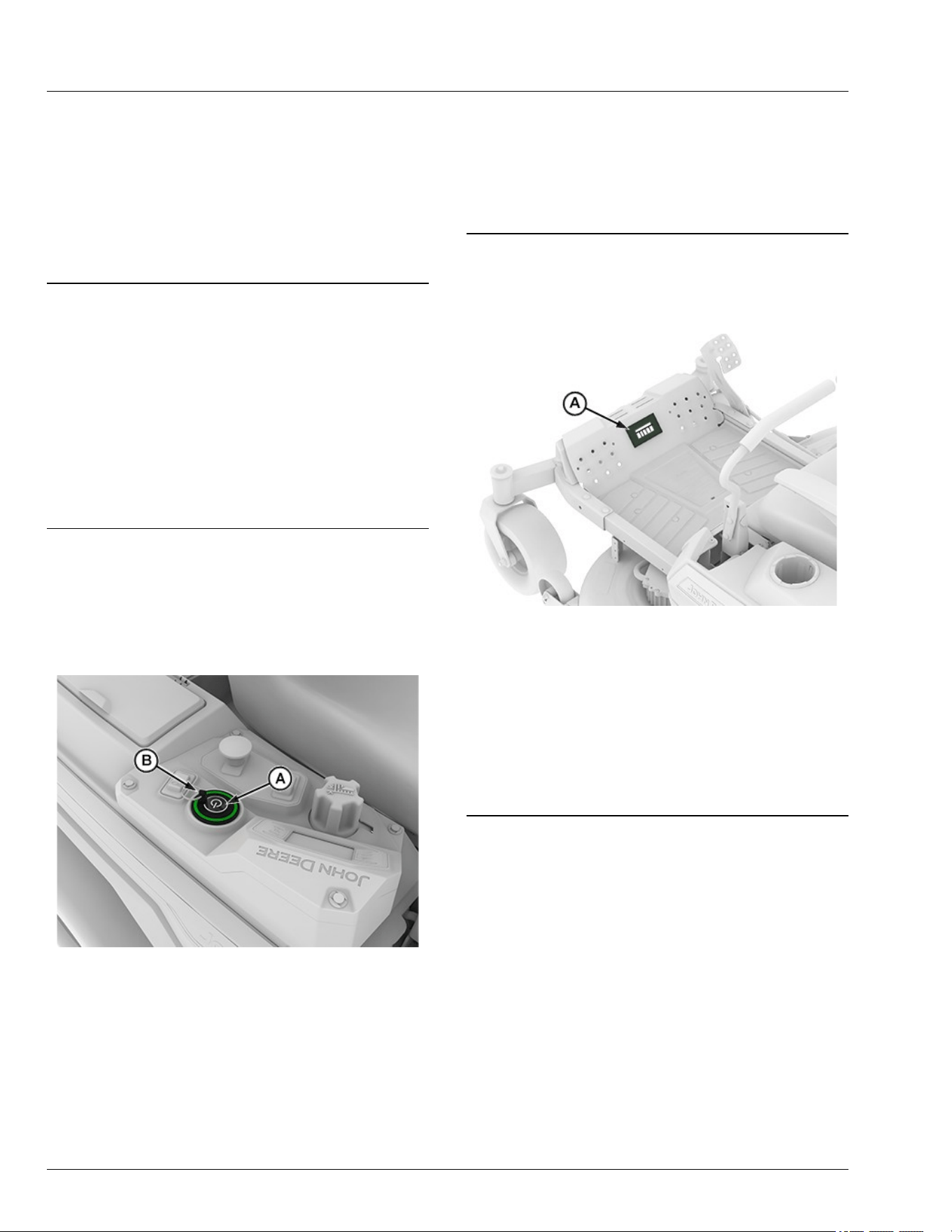
APY545194—UN—13SEP22
● Top of the mower deck, near the electric motor (D).
GX669594—UN—27MAY25
● Battery packs (E).
NOTE: Avoid using solvents when cleaning plastic
parts. Most plastics are susceptible to damage from
various types of commercial solvents and may be
damaged by their use. Use clean cloths to remove
dirt, dust, oil, grease, etc.
GVG6119,1747819093723-19-09JUN25
Machine Cleanout
15-1
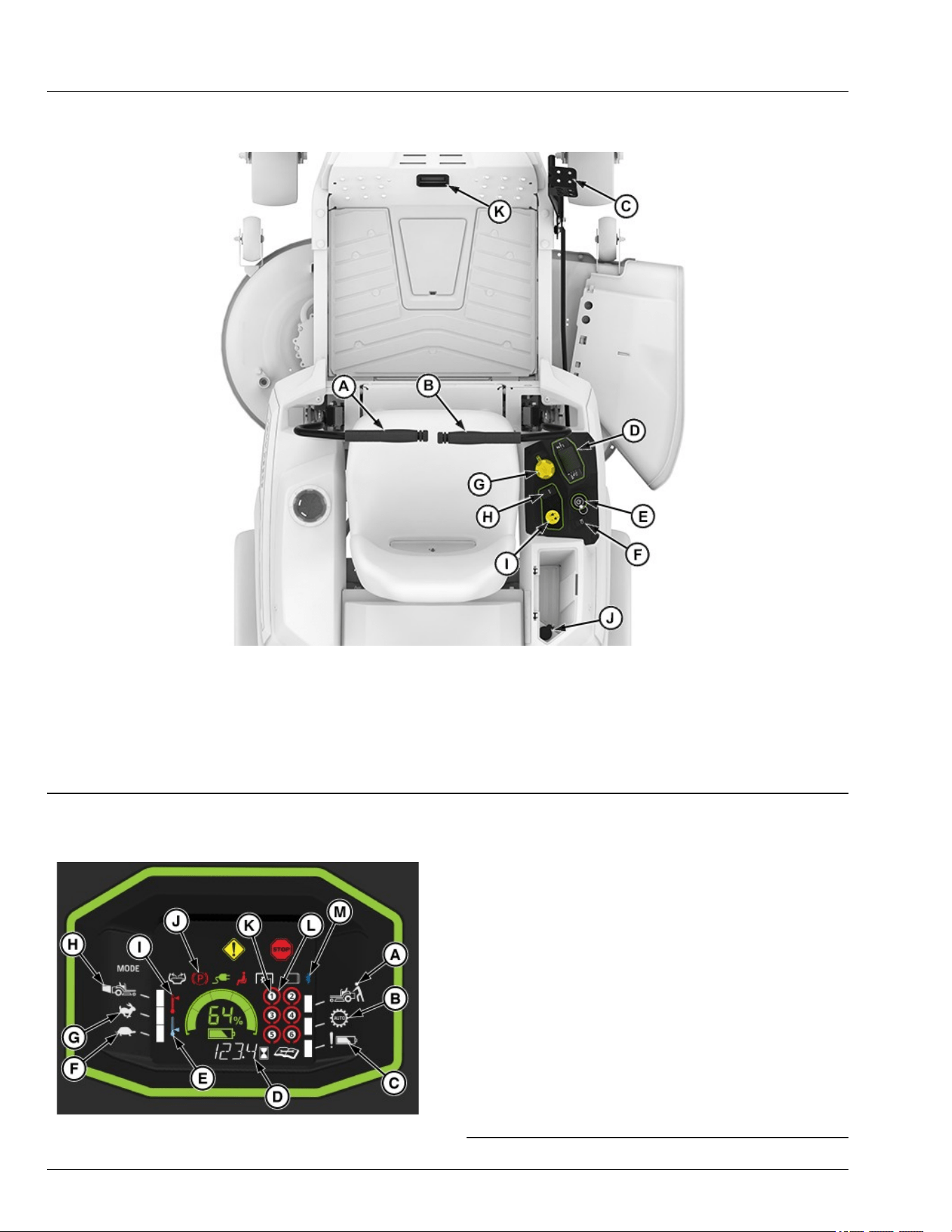
Operator’s Station Controls
APY564714—UN—10FEB23
Operator’s Station Controls shown for Z370R Electric Model
A—Left Motion Control Lever
B—Right Motion Control Lever
C—Mower Deck Lift Pedal
D—Instrument Cluster
E—Power Button and Key Pin
F—Light Switch
G—Height-of-Cut Dial Adjustment
H—Mode Switch
I—Mower Engagement Switch
J—USB-C Port
K—Status Display
gh8xt3t,1675955845722-19-07JUL25
Instrument Cluster
GX669595—UN—04JUL25
A—Push Mode
B—LoadMatch™
C—Battery Attention
D—Hour Meter
E—Low Temperature Alert
F—Low Mode, Standard Blade Speed, Limited Travel Speed
G—High Mode, Standard Blade Speed, Full Travel Speed
H—Bagging Mode, High Blade Speed, Full Travel Speed
I—High Temperature Alert
J—Park Brake
K—Battery Presence X
L—Battery Status X
M—Bluetooth
NOTE: The 42-IN machine oers an optional bagger
attachment. To enhance bagging performance, the
Bagging Mode (E) on the dash increases blade tip
speed and provides additional power for bagging,
or heavier grass conditions.
GVG6119,1752247564094-19-11JUL25
Operating Controls
25-1
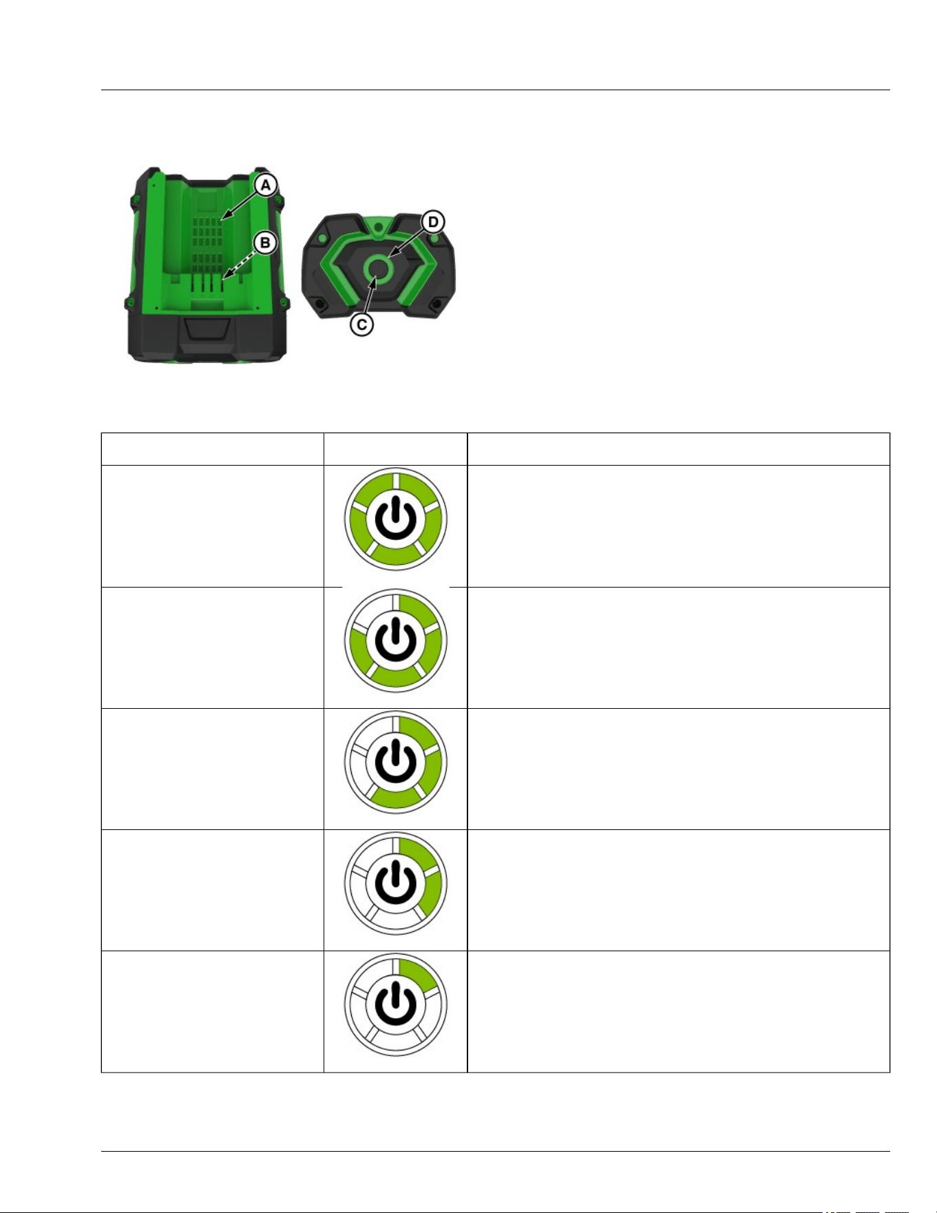
Battery Pack
GX669603—UN—27MAY25
A—Cooling Air Port
B—Battery Contacts
C—Button
D—5-LED Indicator
This lithium-ion battery pack is equipped with a 5-LED
indicator. Press and release the button to display the
charge level or its working condition, and the LED
indicator will last for 10 seconds.
IMPORTANT: If no indicator lights are illuminated on
the battery, the battery may be damaged and
must be replaced.
Battery Charge Level/Working
Condition
5-LED Indicator 5-LED Indicator
Charge Level 80% to 100%
GX669612—UN—04JUL25
5-LED solid green
Charge Level 60% to 80%
GX669611—UN—04JUL25
4-LED solid green
Charge Level 40% to 60%
GX669610—UN—04JUL25
3-LED solid green
Charge Level 20% to 40%
GX669609—UN—04JUL25
2-LED solid green
Charge Level 10% to 20%
GX669608—UN—04JUL25
1-LED solid green
Operating Controls
25-2
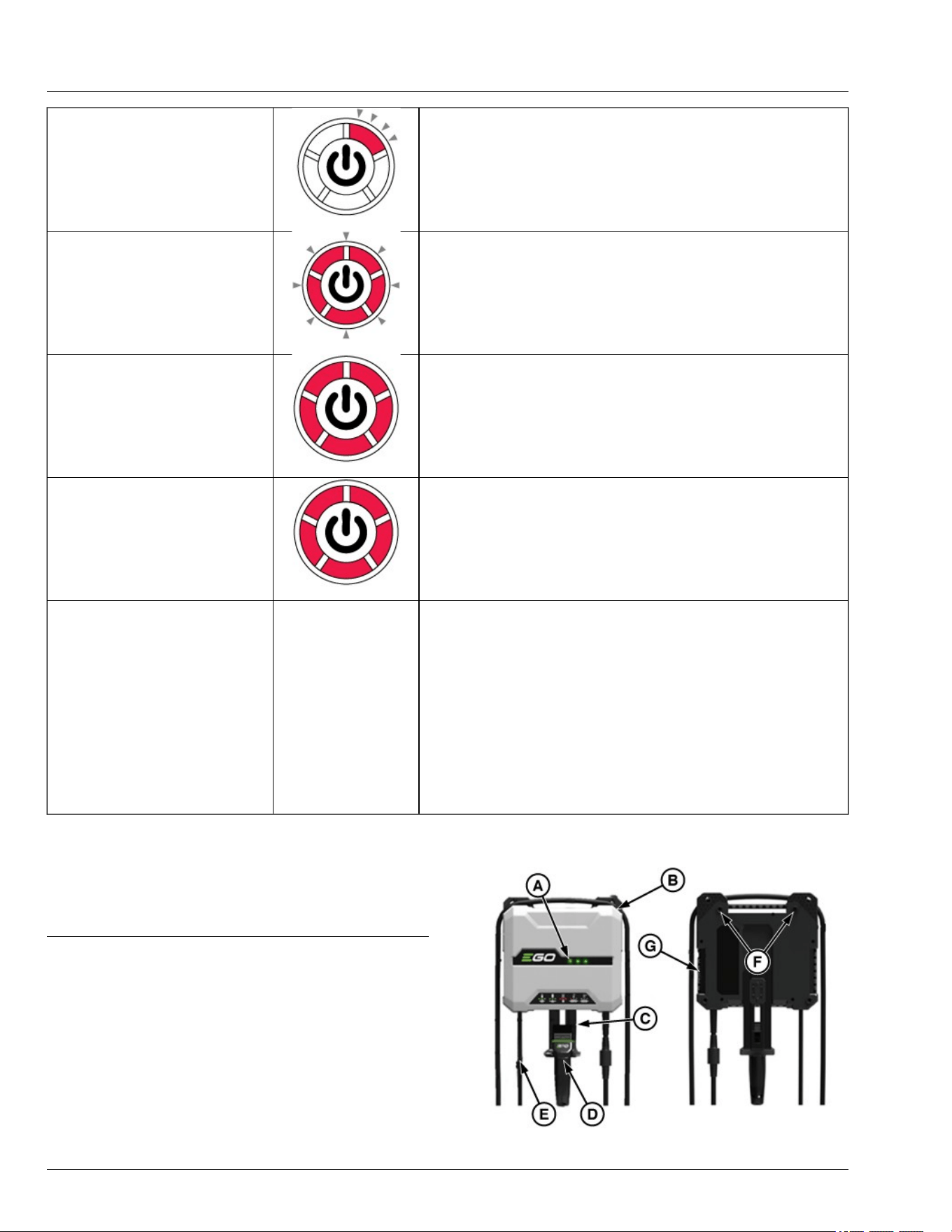
Charge Level less than 10%
GX669613—UN—28MAY25
1-LED ashing red
Low Voltage
GX669614—UN—28MAY25
5-LED rapidly ashing red. The battery pack is nearly depleted and needs to
be charge immediately.
Over Temperature
GX669615—UN—28MAY25
5-LED solid red. Cool the battery pack until the temperature drops below 152°
F (67°C).
Under Temperature
GX669615—UN—28MAY25
5-LED slowly ashing red.
Self-Maintenance
Battery self maintenance can be visually identied by dierent LED color and
ash sequence that may be observed on the battery gauge, which is
dependent on the battery as well as battery manufacturing date. Possible
sequence are noted below.
Sequence 1 :
● 5 LEDs will shine red for 10 Seconds,
● 5 LEDs will turn o for 10 seconds,
● 5 LEDs will turn solid red for 10 seconds.
Sequence will repeat until self maintenance process is complete.
Sequence 2 :
● 5 LEDs will ash green every two seconds.
Sequence will repeat until self maintenance process is complete.
NOTE: If the battery remains unused for approximately
one month, it may enter self-maintenance mode.
During this process, the battery will discharge itself
to approximately 30% capacity.
GVG6119,1748320364388-19-16JUL25
Charger
GX669604—UN—09JUN25
Operating Controls
25-3
A—LED Indicators
B—Winding Groove
C—Hanger
D—Charge Connector
E—Power Cord
F—Wall Mounting Holes
G—Ventilation Openings
IMPORTANT: The safe use of this product requires
an understanding of the information on the
product and in this instruction manual, as well
as knowledge of the project you are attempting.
Before use of this product, familiarize yourself
with all operating feature and safety rules.
LED Indicators
Indicate the charging status. There are three Green/Red
bi-color LED indicators.
Charge Connector
To connect to the mower.
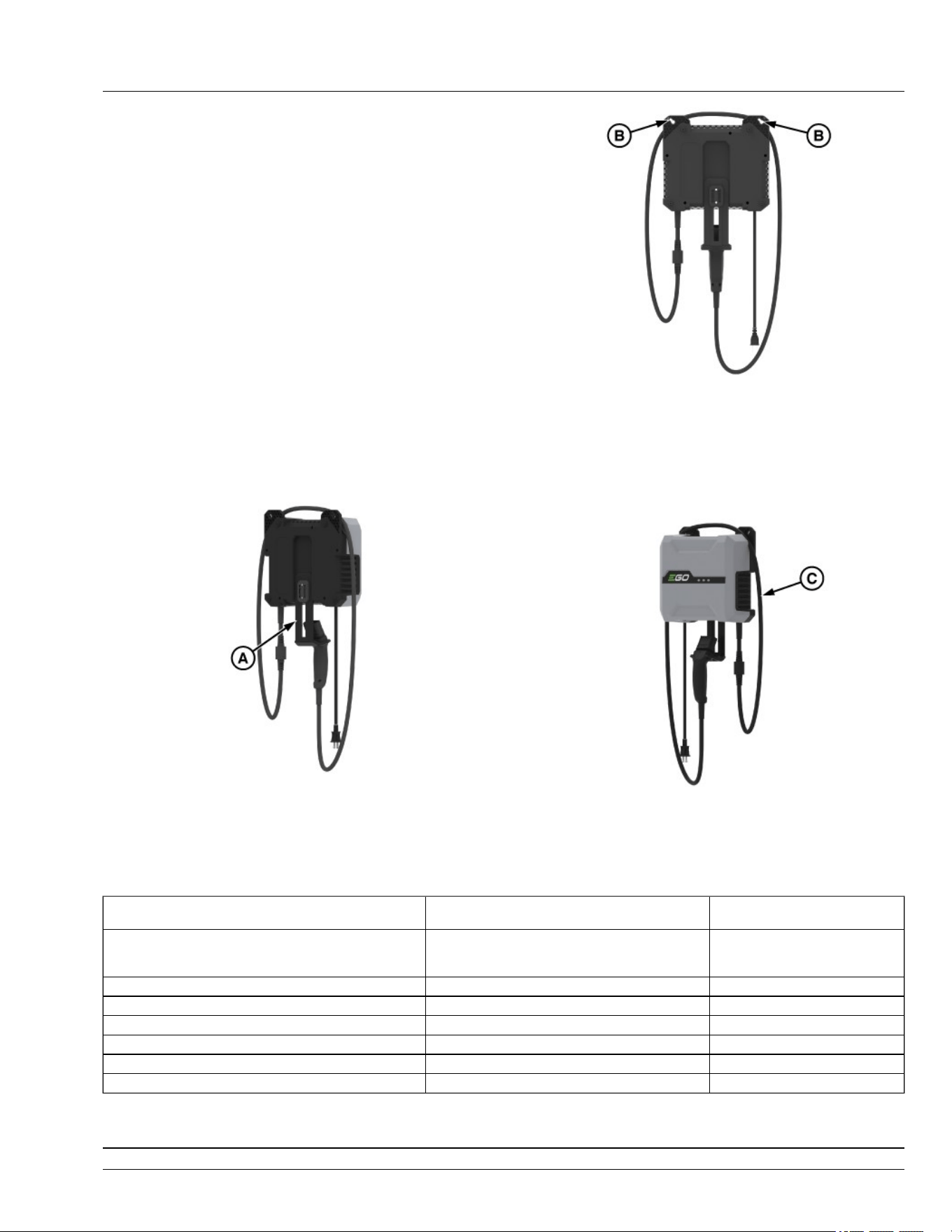
Hanger
GX675574—UN—03JUL25
The hanger is designed for hanging the charge
connector. It can be placed in two positions (A). The
lower position is for hanging the charge connector, and
the higher position is for convenient storage.
Wall-Mounting
GX675575—UN—03JUL25
The charger features wall-mounting holes for
convenient storage (B). Drive screws into the wall 9.7
inches (246.7 mm) apart. Use screws and anchors
suciently strong to support the combined weight of the
charger.
WINDING GROOVE
GX675576—UN—03JUL25
When the charger is hung on the wall, there will be a
groove near the wall-mount holes. The groove can be
used as a winding groove. Wind the power cord in the
winding groove if it is too long to use conveniently (C).
Status LED Indicators on the Charger Power Indicator on the Battery
Pack
Charging Shining green in sequence. Flashing red, orange and green
alternately/ Last segment ashing
green, rest solid green.
Full Charged All LED indicators shining solid green O
Cold/Hot Battery First LED indicator ashing green Shining solid red.
Cold/Overheated charger First LED indicator shining solid red O
The charger’s fan malfunction First LED indicator ashing red O
Charger output overcurrent First two LED indicators shining solid red O
Error All LED indicators shining solid red O
GVG6119,1748322942721-19-30JUN25
Operating Controls
25-4
Daily Operating Checklist
● Check brake system.
● Clean mower deck with washout port after use.
● Check safety interlock system.
● Check tire pressures.
● Check mulch control open/close operation (if
equipped).
vs70618,1664956439431-19-22MAR23
Avoid Damage to Plastic and Painted
Surfaces
● Do not wipe plastic parts until they are rinsed rst.
Using a dry cloth causes scratches.
● Insect repellent spray damages plastic and painted
surfaces. Do not spray insect repellent near
machine.
● Prolonged exposure to sunlight damages some
surfaces.
gh8xt3t,1669983446259-19-02DEC22
Use Power Button
NOTE: 2 batteries (6 Ah or greater) are required to
operate. 4-6 batteries are recommended for optimal
performance.
APY556337—UN—02DEC22
1. Insert key pin (B) next to the power button (A), press
and hold power button to START the machine.
● Armed State: On initial startup, there is an
approximate delay of 3 seconds after the 2
audible beeps before entering the armed mode.
The status bar will show green when the machine
enters the armed state and is ready to mow and
drive.
● Disarmed State: Disarmed state is activated when
the power button is pressed and no audible noise
is heard, turning only the display on. Allows only
the display to be powered on. The machine is not
operable in this state.
2. Press the power button (A) to STOP the machine,
remove key pin (B).
GVG6119,1751272896629-19-08JUL25
Status Display
APY556346—UN—02DEC22
● Status display (A) displays a bar graph of the
battery's charge status.
● Top display bar lights as follows:
- White-Disarmed state
- Green-Armed state
- Flashing Green-Standby Mode
- Red-STOP diagnostic trouble code (DTC)
- Amber-Warning diagnostic trouble code (DTC)
gh8xt3t,1699358541073-19-08NOV23
Operate the Rear Cover
1. Park machine safely. (See Parking Safely in the
Safety section.)
Daily Operations
30-1

GX675596—UN—03JUL25
2. Press the lock (A) to open the rear cover.
GX675597—UN—03JUL25
3. Lift the rear cover (B) upward until it reaches the fully
open position.
GVG6119,1751855303529-19-09JUL25
Mounting and Dismounting Machine
APY564721—UN—17FEB23
IMPORTANT: Avoid damage! Do not step on status
display (B).
NOTE: Do not step on the mower deck when mounting
and dismounting the machine.
1. Mount the machine from the side using the foot plate
(A).
2. Park machine safely before dismounting. (See
Parking Safely in the Safety section.)
3. Keep the foot plate clean.
vs70618,1664956628257-19-12APR23
Adjust Seat
Adjustable Seat
1. Raise the seat from back side as shown.
APY545198—UN—13SEP22
2. Remove the knob (A).
3. Slide seat forward or backward to the desired
position.
4. Reinsert the knob (A).
vs70618,1664956735275-19-19JAN23
Adjust Motion Control Levers
1. Park machine safely. (See Parking Safely in the
Safety section.)
Daily Operations
30-2
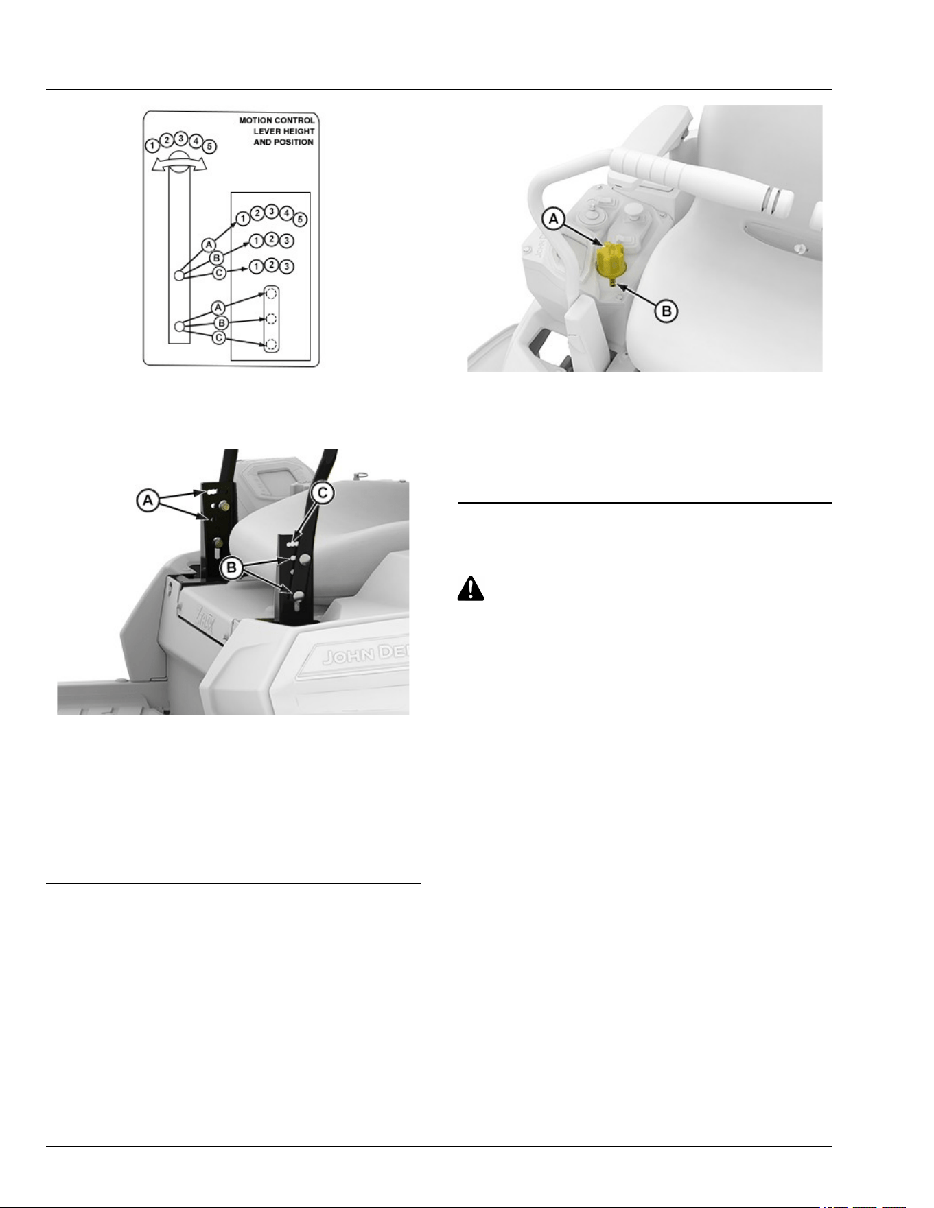
APY536236—UN—08JUN22
2. To adjust the motion control lever height, refer to the
operator instruction label on the machine front panel
and the instructions that follow.
APY545199—UN—13SEP22
3. Remove two bolts and nuts and raise or lower each
control lever to your comfort level.
● For highest lever position, use holes (A).
● For lowest lever position, use holes (B).
4. You can also adjust each motion control lever slightly
forward or rearward (C) within slotted holes.
vs70618,1664956928926-19-11JAN23
Adjust Cutting Height
Cutting height can be adjusted from approximately 31—
114 mm (1.25—4.5 in). Refer to the control lever label
on the front platform.
APY564722—UN—17FEB23
1. Press the lift pedal and rotate dial (A)
counterclockwise to raise mower deck height and
clockwise to lower mower deck height.
2. Rotate dial (A) to index mark (B) to get desired
mower deck height.
gh8xt3t,1670315652721-19-17FEB23
Adjust Mower Wheels
CAUTION: Avoid injury! Rotating blades are
dangerous. Before adjusting or servicing
mower:
• Remove the key pin next to the power button.
• Always wear gloves when handling mower
blades or working near blades.
IMPORTANT: Avoid damage! The mower deck can
be damaged if mower wheels are incorrectly
adjusted:
• Wheels must not ride on ground supporting
mower weight.
• Check wheel adjustment each time cutting
height is changed.
1. Park machine safely on a level surface. (See Parking
Safely in the Safety section.)
2. Inate tires to correct pressure.
3. Move the motion control lever outward to lock
machine in start/shutdown position.
4. Adjust mower wheels to the correct height:
Daily Operations
30-3
42-IN Mower Decks
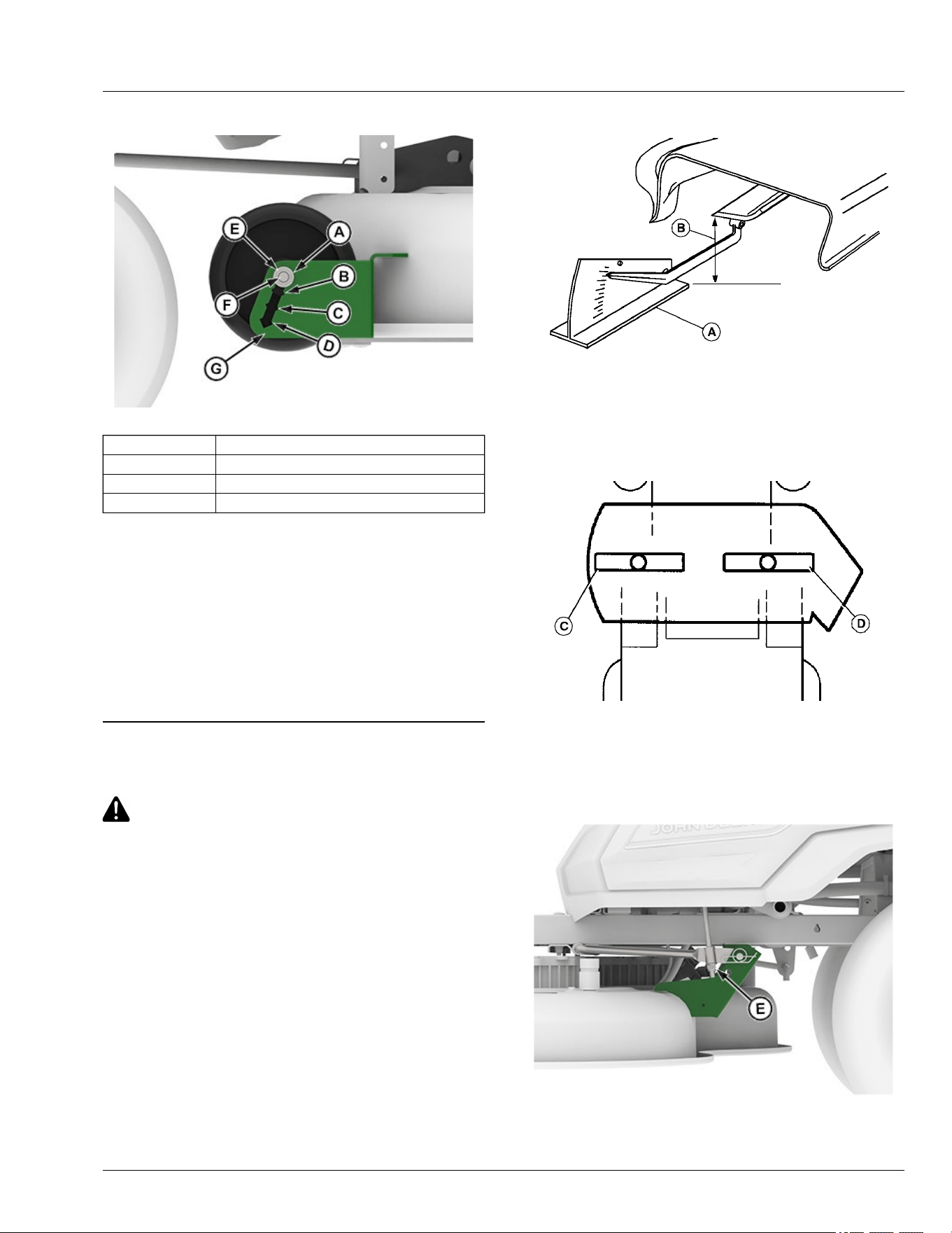
APY545203—UN—13SEP22
Position 1 (A) 31—38 mm (1.25—1-1/2 in) Height of Cut
Position 2 (B) 38—50 mm (1-1/2—2 in) Height of Cut
Position 3 (C) 50—76 mm (2—3 in) Height of Cut
Position 4 (D) 76–101 mm (3—4.5 in) Height of Cut
● Remove nut (E). Pull carriage bolt (F) out until end of
bolt clears the outer wall of the gauge wheel bracket
(G), then slide bolt and wheel assembly to the
desired position.
● Push bolt back through outer wall of bracket. Install
nut (E) and tighten to specication.
Specication
Mower Wheel Nut—Torque. . . . . . . . . . . . . . . . . . 24 N·m (18 lb·ft)
GVG6119,1752247759074-19-11JUL25
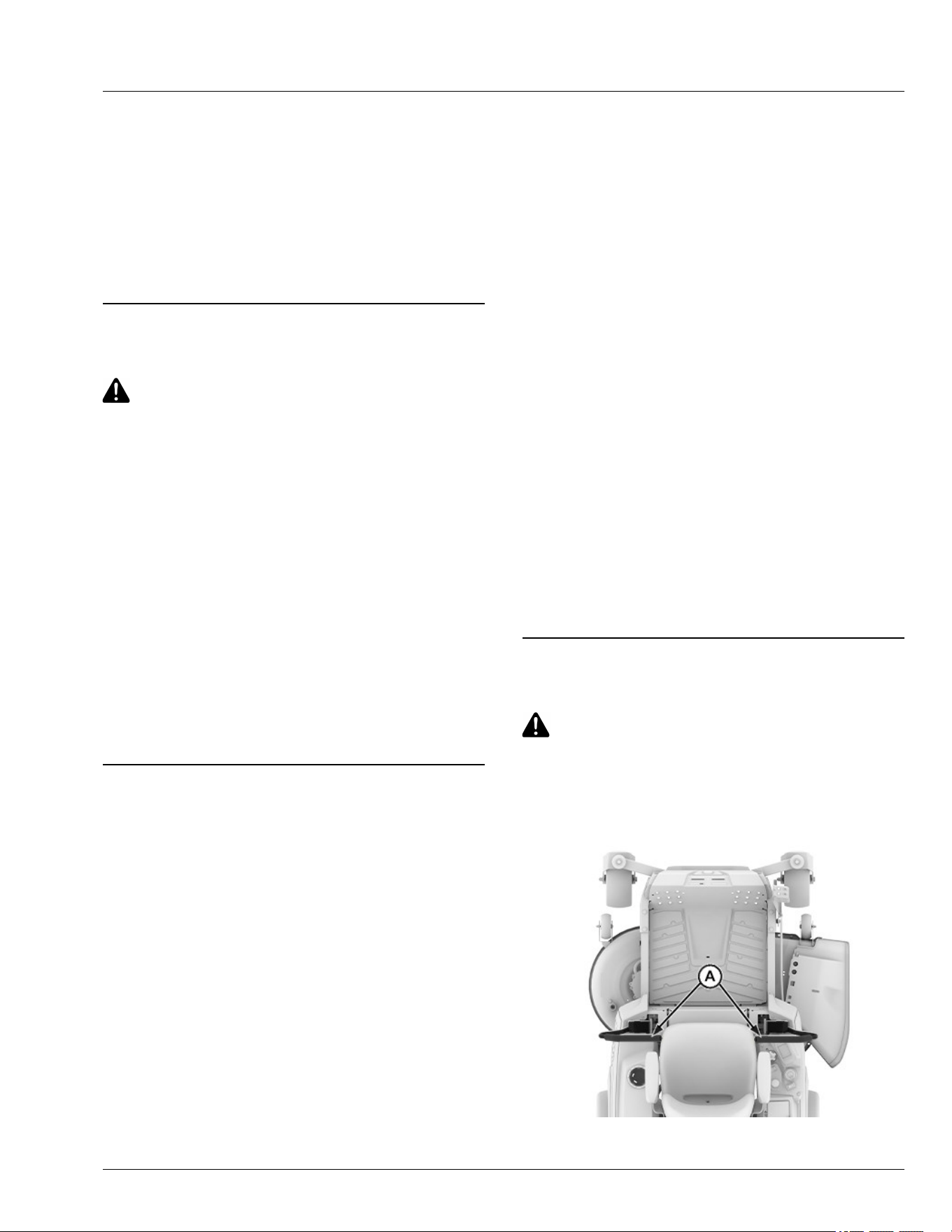
Adjust Mower Level
CAUTION: Avoid injury! Rotating blades are
dangerous.
Before adjusting or servicing mower:
● Remove the key pin next to the power button.
● Always wear gloves when handling mower
blades or working near blades.
NOTE: Mower deck wheels should not contact the
ground when leveling the deck.
1. Park machine safely. (See Parking Safely in the
Safety section.)
2. Inate tires to the correct pressure. (See Tires
pressure in the Specications section.)
3. Position caster wheels to the forward driving position.
4. Set mower to preferred cutting height and lower deck
into the mowing position.
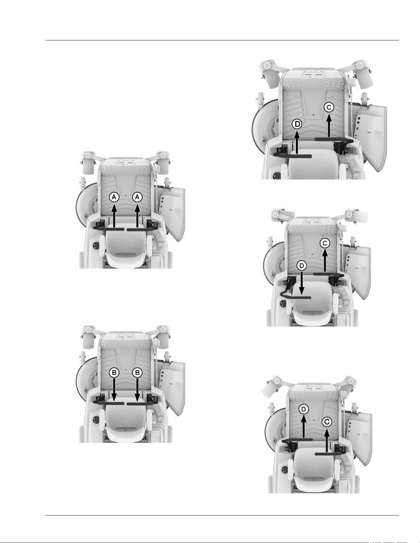
5. Measure mower level (side-to-side).
MXAL42797—UN—09APR13
A convenient leveling gauge (A) (AM130907) is available
from dealer.
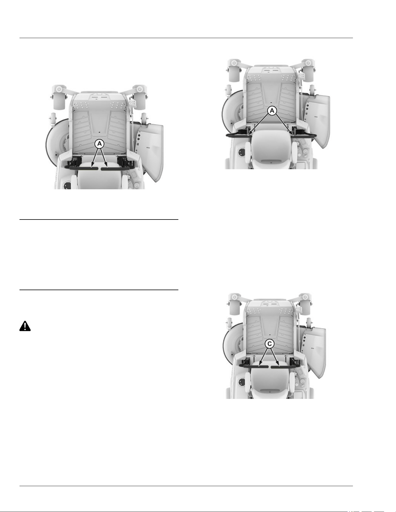
a. Position mower blades as follows and measure
from each outside blade tip (B) to the level
surface.
MXAL42798—UN—09APR13
b. Turn left blade (C) as shown. Turn the right
blade (D) as shown. Take measurement for both
blades.
The dierence between blade measurements
must not be more than 3 mm (1/8 in).
APY545201—UN—13SEP22
c. If necessary, adjust mower lever by turning nuts
(E) clockwise to raise the side of the mower
Daily Operations
30-4
deck, or counterclockwise to lower the mower
deck.
NOTE: Ensure that bottom of the lock nut is fully
engaged on the threaded tting to avoid
hardware loosening during operation.
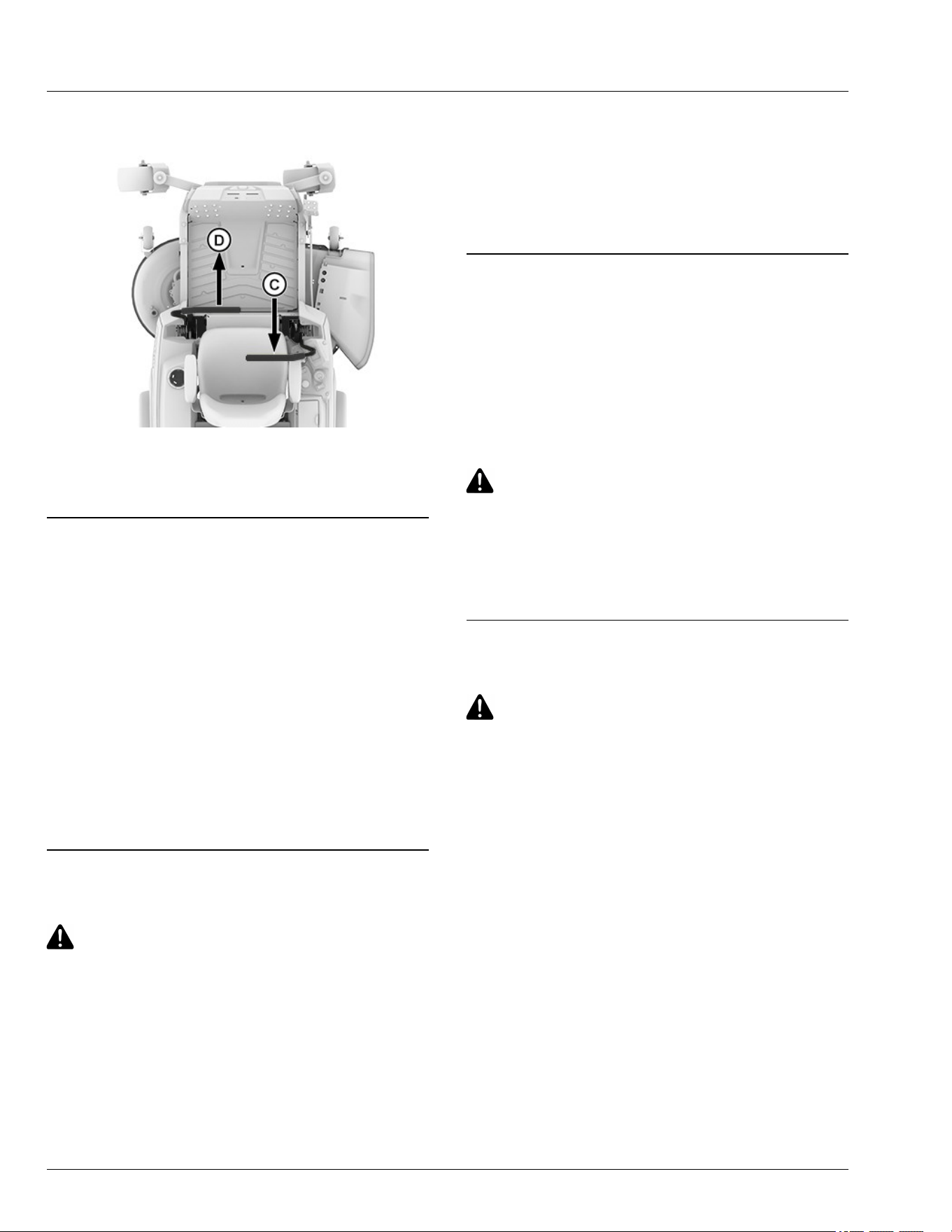
6. Measure mower level (front-to-rear).
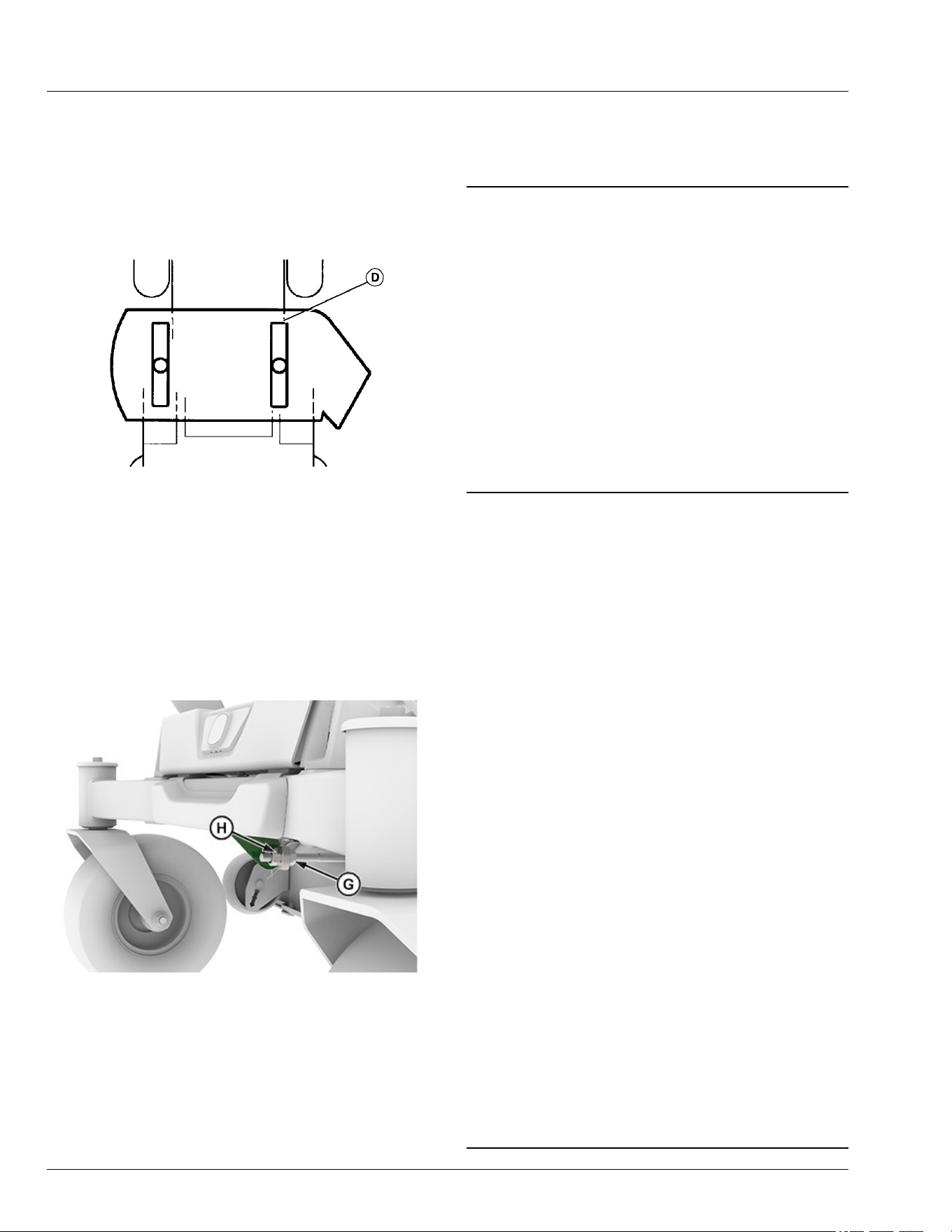
MXAL42800—UN—09APR13
a. Turn right blade (D) so that a blade tip points
straight forward.
b. Measure from the blade tip to the surface. Take
measurement for both blades. The front blade
tips must be lower than the rear blade tips
according to the specication listed.
Specication
Front-to-Rear Blade Tip
Variation—Height. . . . . . . . . . . . . . . . . . . . . 3—6 mm (1/8—1/4 in)
c. 42-IN Mower Deck
APY545202—UN—13SEP22
● Adjust the mower front-to-rear level by
loosening rear nut (G) on the front lift rod.
● Turn front nut (H) clockwise to raise front of
mower or counterclockwise to lower it.
● Tighten rear nut (G) after adjustment is
complete.
●
Specication
Front Nut—Torque. . . . . . . . . . . . . . . . . . . . . . . . . . .. . . . . 27 N·m
(20 lb·ft)
GVG6119,1752247852363-19-11JUL25
Test Safety Systems
The safety systems installed on your machine should be
checked before each machine use. Be sure to read the
machine Operator's Manual and are familiar with the
operation of the machine before performing these safety
system checks.
Use the following checkout procedures for normal
operation of machine.
If there is a malfunction during one of these procedures,
do not operate machine. See your service provider.
Perform these tests in a clear open area. Keep
bystanders away.
vs70618,1664959835621-19-10JUL25
Test Park Brake Switch
1. Park machine safely. (See Parking Safely in the
Safety section.)
2. Sit on operator's seat.
3. Test 1:
a. Move right motion control lever inward to the
neutral position.
b. Press and hold power button for at least 2
seconds.
Result: If 2 beeps are heard, the machine has failed
the test.
4. Return right motion control lever to fully outward
position.
5. Power down the machine.
NOTE: Machine will turn on but will not go into armed
mode. Operator should not hear 2 beeps at this
stage.
6. Test 2:
a. Move left motion control lever inward to the
neutral position.
b. Press and hold power button for at least 2
seconds.
Result: If 2 beeps are heard, the machine has failed
the test.
7. Return left motion control lever to fully outward
position.
GVG6119,1751275336266-19-08JUL25
Daily Operations
30-5
Test Park Brake
1. Park machine safely. (See Parking Safely in the
Safety section.)
2. Lock the park brake by moving the motion control
levers fully outward.
3. Try to push machine manually.
Result: Park brake must prevent machine from moving.
If machine moves, see the service provider for service.
gh8xt3t,1676037877908-19-16JUL25
Test Mower Engagement (PTO) Switch
CAUTION: Avoid injury! The mower blades
should stop in approximately ve seconds
when the mower or PTO is disengaged.
If you believe that your blades may not be
stopping in that period of time, take your
machine to your service provider where they
can safely check and service your machine.
1. Park machine safely. (See Parking Safely in the
Safety section.)
2. Sit on operator's seat.
3. Lock the park brake by moving motion control levers
fully outward.
4. Pull mower engagement (PTO) switch up to engage.
5. Press and hold power button for at least 2 seconds.
Result: Machine must not enter armed state. If machine
enters armed state, there is a problem with the safety
interlock circuit.
gh8xt3t,1700547646914-19-16JUL25
Test Seat Switch
1. Park machine safely. (See Parking Safely in the
Safety section.)
2. Test 1:
a. Lock the park brake by moving the motion
control levers fully outward.
b. Sit on operator's seat.
c. Start the machine into armed state. (See Use
Power Button in Daily Operation section.)
d. Move motion control levers inward to neutral
position.
e. Pull mower engagement switch (PTO) up to
engage.
f. Raise up slightly o the seat. Do not get o
machine.
Result: The PTO blades should stop. If the PTO
blades do not stop, there is a problem with the
safety interlock circuit.
g. Return to sitting position in operator's seat.
h. Return motion control levers to the fully outward
position.
i. Push mower engagement switch (PTO) down to
disengage.
j. Turn machine o.
3. Test 2:
a. Lock the park brake by moving the motion
control levers fully outward.
b. Sit on operator's seat.
c. Power ON mower and enter armed state. (See
Use Power Button in Daily Operation section.)
d. Get up slightly o the seat. Do not get o
machine.
Result: Machine will beep, enter standby mode,
and top status bar will blink green. If the
machine does not enter standby mode, there is
a problem with the safety interlock circuit.
e. Return to sitting position in operator's seat.
f. Turn machine o.
GVG6119,1751275490040-19-08JUL25
Use Park Brake
CAUTION: Avoid injury! Children or bystanders
may attempt to move or operate an unattended
machine. Always lock the park brake and
remove the key pin before leaving the machine
unattended.
Locking Park Brake
APY545204—UN—13SEP22
Daily Operations
30-6
To lock the park brake, move motion control levers (A)
fully outward.
Unlocking Park Brake
APY545205—UN—13SEP22
To unlock the park brake, move motion control levers
(A) inward to neutral position.
vs70618,1664963964281-19-11JAN23
Using Mower Engagement Switch
● To Engage Mower - Pull mower engagement knob
up.
● To Disengage Mower - Push mower engagement
knob down.
MP47322,00F463F-19-15MAR13
Use the Motion Control Levers
CAUTION: Avoid injury! Learn to use the motion
control levers and practice at low mode limited
travel speed until becoming procient and
comfortable with the operation of the machine.
Do not move motion control levers from
forward to reverse or reverse to forward
position rapidly. Sudden direction change
causes loss of control or damages the machine.
Use low limited travel speed mode to learn to drive the
machine become familiar with the motion control levers
and how they respond. It is essential to know how the
machine accelerates, steers, and stops.
The functions of the motion control levers are:
● Dual function neutral position
● Steering
● Acceleration
● Braking
Start/Shutdown Position
APY545206—UN—13SEP22
● Motion control levers must be placed fully outward
(A). This position engages the park brake and allows
the operator to start the machine.
● Forward and reverse movement of the motion control
levers is prevented when levers are moved fully
outward to the start/shutdown position.
● Operator can exit mower when machine is running,
when the mower blades are not engaged and the
motion control levers are fully outward. (See Standby
Mode in Daily Operations section.)
● Motion control levers must be fully outward to safely
enter and exit the operator’s seat.
Neutral Position
APY545207—UN—13SEP22
● Machine speed, motion, and direction can be
controlled when the machine is running and motion
control levers are in the neutral position (C).
● To stop the machine for an emergency, move the
motion control levers quickly back to the neutral
position.
Daily Operations
30-7
Forward and Reverse Travel
1. Move both motion control levers from the start/
shutdown position inward to the neutral position.
2. Move the motion control levers forward to begin
forward travel.
3. Move the motion control levers rearward to begin
reverse travel.
4. To stop travel, move motion control levers back to the
neutral position.
Forward Travel
APY545208—UN—13SEP22
Gradually move both motion control levers evenly
forward (A) from neutral. To speed up, move the levers
farther forward. To slow down smoothly, slowly move the
levers toward neutral.
Reverse Travel
APY545209—UN—13SEP22
Look down and behind when evenly moving both motion
control levers backward (B) from neutral. To speed up,
move the levers farther rearward. To slow down
smoothly, slowly move the levers toward neutral.
Left Turn
APY556362—UN—06DEC22
1. To turn slightly to the left, push right control lever (C)
further forward than the left control lever (D).
APY545211—UN—13SEP22
2. To turn sharply to the left, push right control lever (C)
forward and pull left control lever (D) rearward at the
same time.
Right Turn
APY556361—UN—06DEC22
Daily Operations
30-8
1. To turn slightly to the right, push left control lever (D)
further forward than the right control lever (C).
APY545213—UN—13SEP22
2. To turn sharply to the right, push left control lever (D)
forward and pull right control lever (C) rearward at
the same time.
gh8xt3t,1700663044379-19-22NOV23
Start the Machine
1. Sit on the operator’s seat.
2. Set both motion control levers fully outward to the
start/shutdown position.
3. Push the mower engagement switch down and
conrm that mower blades are not engaged.
4. Insert the key pin next to the power button, press and
hold the power button until 2 audible beeps are heard
to initiate arming of the machine. The machine is
armed when the status bar turns green. (See Status
Display in the Daily Operations section.)
5. Set both motion control levers to the neutral position
from the start/shutdown position.
gh8xt3t,1699358688237-19-08JUL25
Engage Mower
CAUTION: Avoid injury! Clear mowing area of
all bystanders when operating this machine.
Thrown objects cause serious injury or death.
Keep hands and feet away from blades and
discharge opening.
Do not mow in reverse unless necessary.
1. Adjust mower to desired cutting height.
2. Start the machine.
3. Move both motion control levers to the neutral
position from the start/shutdown position.
4. Pull mower engagement switch to engage mower.
NOTE: The amount that the control levers are moved
varies the travel speed and turn rate.
5. Push motion control levers forward slowly. Mow at
safe travel speed.
vs70618,1664965462086-19-19JAN23
Stop the Machine
1. Stop machine on a at, level surface.
2. Push the mower engagement switch to disengage
mower
3. Lock the park brake by moving the motion control
levers fully outward.
4. Press the power button to STOP the machine.
CAUTION: Avoid injury! Children or bystanders
may attempt to move or operate an unattended
machine.
Always lock the park brake and remove the key
pin before leaving the machine unattended.
5. Remove key pin.
gh8xt3t,1672752981109-19-19JAN23
Use MulchControl (If Equipped)
CAUTION: Avoid injury! Rotating blades are
dangerous.
1. Park machine on a at, level surface.
2. Disengage mower blades.
3. Lock the park brake by moving both motion control
levers fully outward to start/shutdown position.
4. Wait for all moving parts to stop before leaving the
operator's station.
Daily Operations
30-9
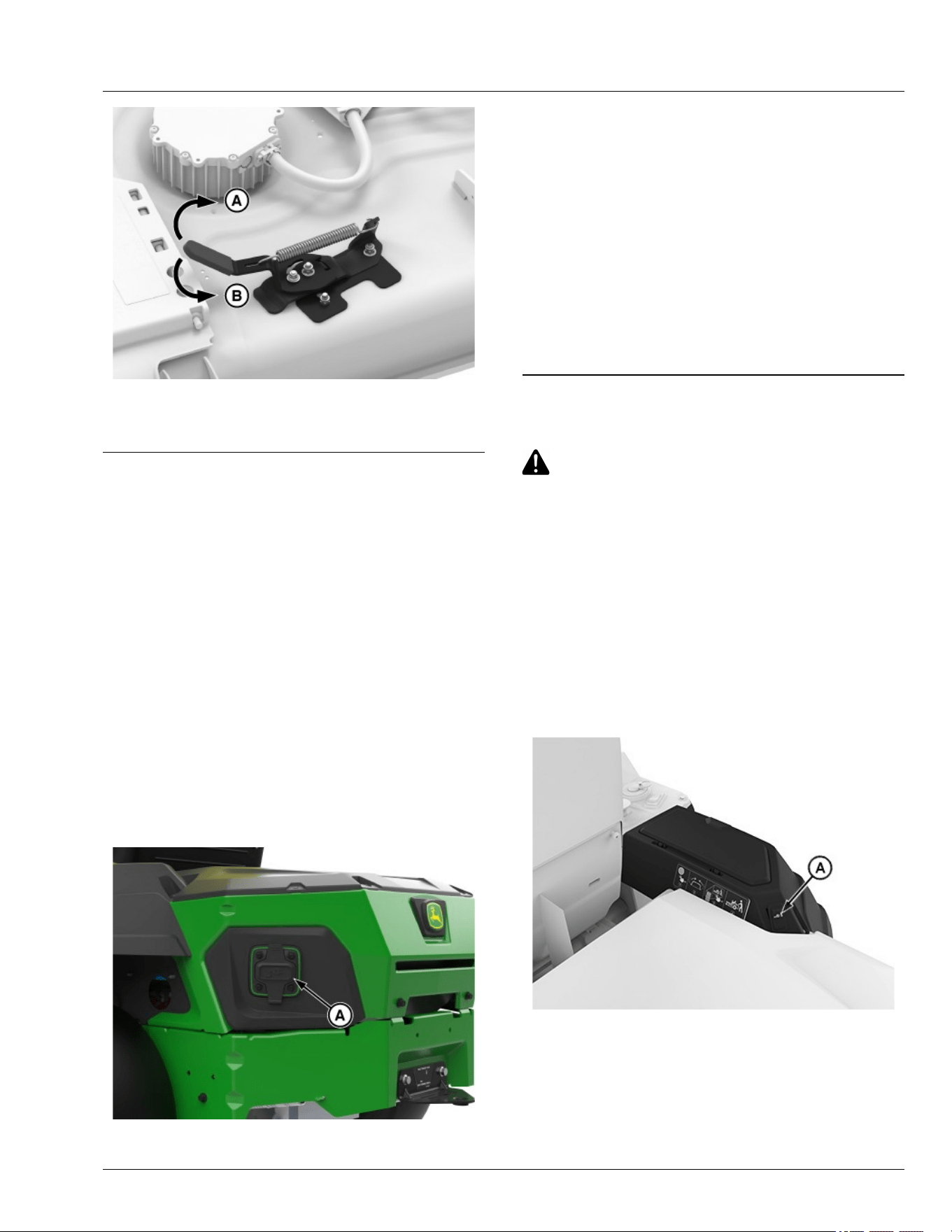
APY556336—UN—07JUL25
5. Rotate lever clockwise (A) to close or
counterclockwise (B) to open discharge plate.
gh8xt3t,1668084560546-19-16MAY24
Use Charging Port
IMPORTANT: Avoid damage! Do not move machine
while battery is charging.
NOTE: Leaving the machine connected to the charger
when charging is complete will not impact battery
life or function.
NOTE: Lithium-ion battery packs are shipped partially
charged. Before using it the rst time, fully charge
the battery pack.
1. Charge machine safely. Do not handle charging cord
with wet hands, while standing in water, or when cord
is routed through standing water or wet grass. (See
Charging your Machine Safely and Use Caution in
Wet Conditions in the Safety section.)
2. Use an appropriate charger cord rated for use.
GX669596—UN—27MAY25
A—Charging Port
3. Open cover to charger port (A) for charging the
machine.
4. Connect charging cord to the machine.
5. Display backlight will remain on until battery reaches
100% (SOC) State of charge.
NOTE: It is not necessary to run down the battery pack
charge before recharging. The lithium-ion battery
can be charged at any time and will not develop a
"memory" when charged after only a partial
discharge.
6. After charging, replace cover to charging port.
GVG6119,1748234722045-19-16JUL25
Manually Moving Machine
CAUTION: Avoid injury! When the machine is in
push mode, it may move abruptly.
Do not use push mode when the machine is
stopped on an incline to prevent it from going
downhill out of control.
Moving Machine with Push Mode Active:
1. Ensure machine is OFF and motion control levers
are fully outward in start/shutdown position.
2. Press the power button briey, ensuring no audible
beeps are heard and the status display bar is white,
indicating the disarmed state.
3. Standing next to the machine, move control levers to
inward/neutral position.
APY556356—UN—09FEB23
4. Press the push mode switch (A).
Daily Operations
30-10

GX675603—UN—16JUL25
5. Before moving the machine to the desired location,
ensure that push mode (B) appears on the ICC
display.
NOTE: Do not allow vehicle speed to exceed 7 mph
while in push mode.
Moving Machine without Push Mode Active or When
Unable to Use Switch.
1. Standing next to the machine, move control levers to
inward/neutral position.
2. Push the machine no faster than a speed of 1.5mph.
NOTE: Exceeding 1.5 mph will cause brakes to be
applied. If this occurs, wait for machine to stop,
then begin pushing again.
gh8xt3t,1699527008734-19-10JUL25
Unclog Mower
CAUTION: Avoid injury! Do not attempt to
unclog attachment with machine running.
Rotating blades are dangerous. Shut o the
machine and remove the key pin before getting
o the seat to inspect the machine and
attachment.
Thrown objects can cause serious injury. Make
sure that all machine parts are stopped before
raising hopper top or removing chutes.
1. Park machine safely remove the key pin. Wait for all
moving parts to stop before leaving the operator’s
station to inspect machine.
2. Check under mower deck and discharge chute for
debris.
3. Clear all debris before using mower.
4. If clogging occurs, switch to open mode to allow
some grass to discharge.
gh8xt3t,1699368990951-19-08NOV23
Unclog Mower, Bagger, or Material
Collection System
CAUTION: Avoid injury! Do not attempt to
unclog attachment with the machine running.
● Rotating blades are dangerous. Turn the
machine o and remove the key pin before
getting o the seat to inspect the machine
and attachment.
● Thrown objects cause serious injury. Make
sure that all machine parts are stopped
before raising hopper top or removing
chutes.
Checking for Clogging While Driving
If grass builds up in the front of the mower discharge
chute, check for clogged chute or problems with blower
assembly (if equipped).
If there is a trail of clippings behind mower or clippings
blow to the side, check for clogged chute, full collector
bags, or problems with blower assembly.
Removing Debris from Inspection Points:
CAUTION: Avoid injury! Do not use hands or
feet to clear clogged mower deck or blower
assembly. Stored energy cause blades to
rotate.
1. Park machine safely. (See Parking Safely in the
Safety section.) Wait for all moving parts to stop
before getting o to inspect machine.
2. Open hopper cover. Check chute outlet.
3. Remove chute from the mower deck or blower
assembly. Check chute inlet.
4. Check under the mower deck for debris.
gh8xt3t,1668086816572-19-12APR23
Use Wash Port to Clean Mower Deck
NOTE: Follow this procedure after each use to prevent
buildup and remove corrosive lawn chemicals.
1. Park machine safely. (See Parking Safely in the
Safety section.)
Daily Operations
30-11
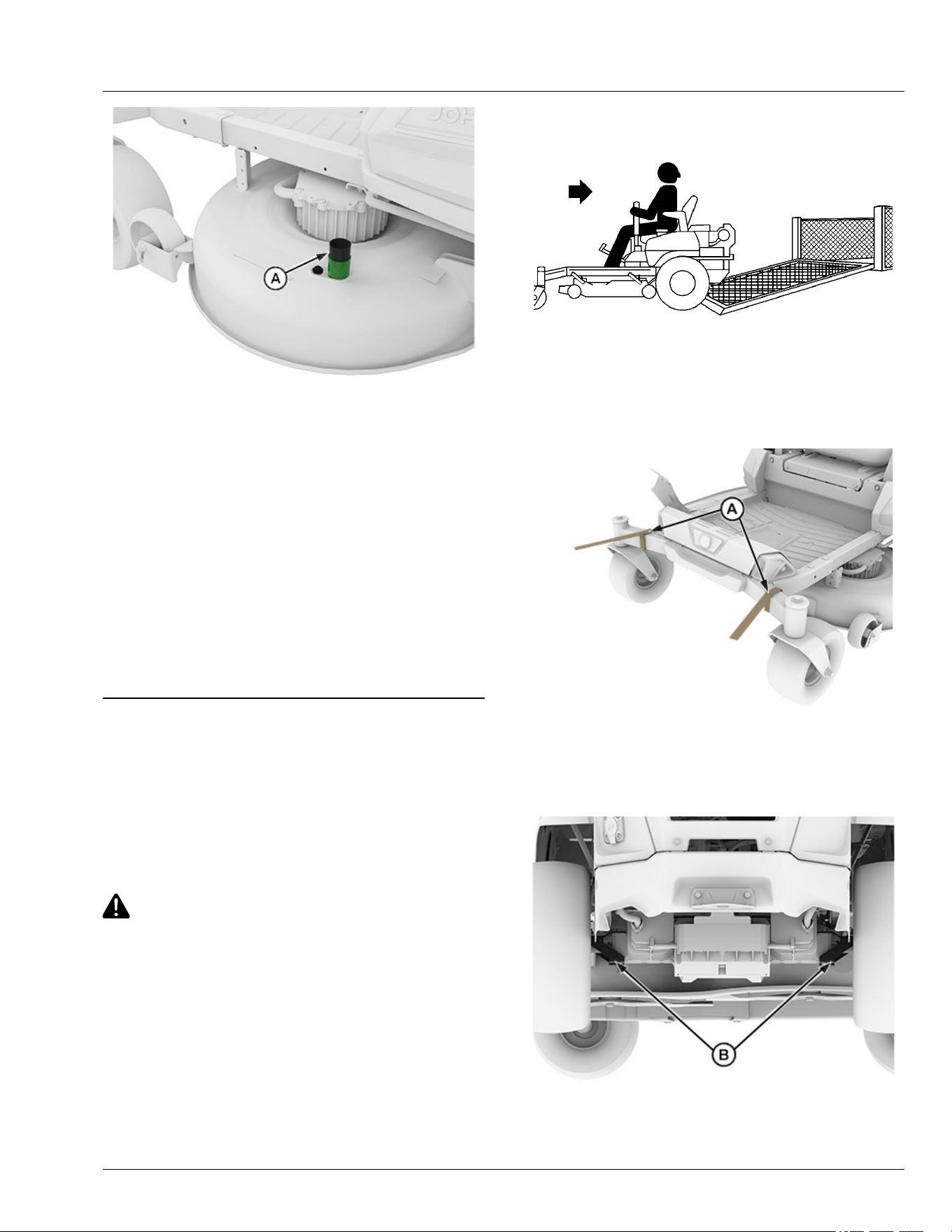
APY564716—UN—15FEB23
2. Attach quick coupler to the garden hose.
3. Attach garden hose with the quick coupler to wash
port (A) on the mower deck.
4. Turn on water.
5. Start the machine.
6. Engage blades while in Bagging mode.
7. Flush water under the deck for approximately one
minute.
8. Disengage mower blades.
9. Stop machine.
10. Turn o water and remove quick coupler from the
wash port and garden hose.
gh8xt3t,1715692497745-19-14MAY24
Transport Machine on Trailer
NOTE: Trailer capacity must exceed combined machine
weight and attachment weight. (See Specications
section in Operator’s Manual.)
Ensure that trailer has all the necessary lights and signs
required by law.
CAUTION: Avoid injury! Use extra care when
loading or unloading the machine onto a trailer
or truck. Machine wheels can go o the ramp or
trailer, causing the machine to tip over.
● To load, back up slowly and in a straight line.
Keep wheels away from drop-os and edges.
● Do not use two separate loading ramps. Use
full width loading ramp at least 30 cm (12 in)
wider than machine to keep caster wheels
from going o the ramp edge.
● Use a trailer with sides.
1. Park trailer on level surface.
2. Fully raise mower deck before driving machine onto
trailer.
MXAL42817—UN—09APR13
3. Back machine onto heavy-duty trailer with full-width
ramp.
4. Lower mower deck completely.
5. Park machine safely (See Parking Safely in the
Safety section.)
APY545214—UN—13SEP22
6. Fasten front of machine at both sides of the frame at
points (A) to trailer with heavy-duty straps, chains, or
cables. Straps must be directed down, forward, and
outward from machine.
APY551601—UN—08NOV22
7. Fasten rear of machine at both sides of frame at
points (B) to trailer with heavy-duty straps, chains, or
Daily Operations
30-12

cables. Straps must be directed down, rearward, and
outward from machine.
gh8xt3t,1699527281836-19-17JUN25
Transporting Material Collection System (If
Equipped)
If the material collection system is left on the machine
during transport, follow these guidelines when trailering
the unit:
● Empty the cloth bags and remove them from the
hopper. Full bags add extra weight which can
overstress the hopper frame on rough roads. At road
travel speeds, wind can cause premature wear of the
cloth bags.
● Make sure that the hopper cover is latched securely
to the hopper frame.
● If the unit is transported over long distances or at
high speeds, remove the rear bagger or power ow
chute before transport.
TH84124,000020A-19-10APR19
Tow Loads
IMPORTANT: Avoid damage! Towing excessive
trailer loads can stress drivetrain components.
To avoid damage to drivetrain components, use
the following guidelines.
● Do not exceed maximum towing capacity of 113.4 kg
(250 lbs).
● Do not exceed maximum tongue weight of 45.4 kg
(100 lbs).
● Avoid inclines greater than a 13 degrees slope while
towing to avoid damage to the pulling machine. Use
the Slope Guide located in this Operator’s Manual to
ensure proper machine towing operation. See
Operating on Slopes in the Safety section for
additional information.
● Avoid making sharp turns. Make wide turns to avoid
jack-kning.
● Travel slowly and allow extra stopping distance.
gh8xt3t,1669986929895-19-25MAY25
Mowing Tips
● Mow grass when it is dry.
● Stay at least two mowing widths away from ditches,
drop-os, or water to avoid accident.
● Keep mower deck and discharge chute clean.
● Mow with sharp blades.
● Properly level mower deck for a smooth cut.
● Mow grass frequently.
● Use a travel speed that ts the conditions:
- Mow tall or wet grass twice. With the rst pass, cut
grass halfway to desired height. With the second
pass, cut to the desired height.
- Travel slowly when mowing tall or thick grass.
- Avoid damaging grass by slipping or skidding
machine drive wheels. Practice smooth control
lever movements.
- When performing sharp turns, do not allow inside
machine drive wheel to stop and twist on grass.
gh8xt3t,1670309911078-19-19JAN23
Blade Choices
Several types of blades are available for Z300 series
mowers:
42-IN Decks
● Dedicated Side discharge blades. These blades are
designed for optimal performance when side
discharging, and are installed on Z300 Series 42-IN
mower when shipped from the factory.
● Mulching blades. These blades are designed for
optimal performance when used with a mulch
control.
● Bagging blades (42-IN Deck Only). These blades are
designed for optimal performance when used with a
Z300 series bagger.
NOTE: Side discharge blades for electric mowers dier
from those for gas mowers to maximize mower
runtime. It is not recommended to use blades
designed for gas mowers on this mower.
GVG6119,1752248032987-19-11JUL25
Standby Mode
To enter into standby mode:
● Park machine safely. (See Parking Safely in the
Safety section.)
● Press and hold power button until 2 audible beeps
are heard to enter the armed state.
● The machine will remain in standby mode for ~2
minutes when the operator is o the seat.
● After 2 minutes, the vehicle will enter into disarmed
mode requiring the operator to rearm the machine.
If the operator returns to the seat prior to the standby
mode timeout, the machine will return to armed mode
and the operator can resume traction and mowing
functions without interacting with the power button.
GVG6119,1751283901744-19-30JUN25
Daily Operations
30-13

Servicing Machine
IMPORTANT: Avoid damage! Operating in extreme
conditions may require more frequent service
intervals:
Machine components may become dirty or
clogged when operating in extreme heat, dust
or other severe conditions.
Please use the following timetables to perform routine
maintenance on the machine.
Park the vehicle safely. (See Parking Safely in the
Safety section.)
GVG6119,1751284176049-19-30JUN25
Service Intervals
Every 8 Hours or Daily
● Check brake system.
● Clean mower deck with washout port after use.
● Check safety interlock system.
● Check tire pressure.
Every 50 Hours or Yearly (Whichever Comes First)
● Check mower deck level.
Every 100 Hours or Yearly (Whichever Comes First)
● Sharpen/replace mower blades.
● Clean underside of mower deck.
gh8xt3t,1672296836923-19-15FEB23
Service Intervals
35-1
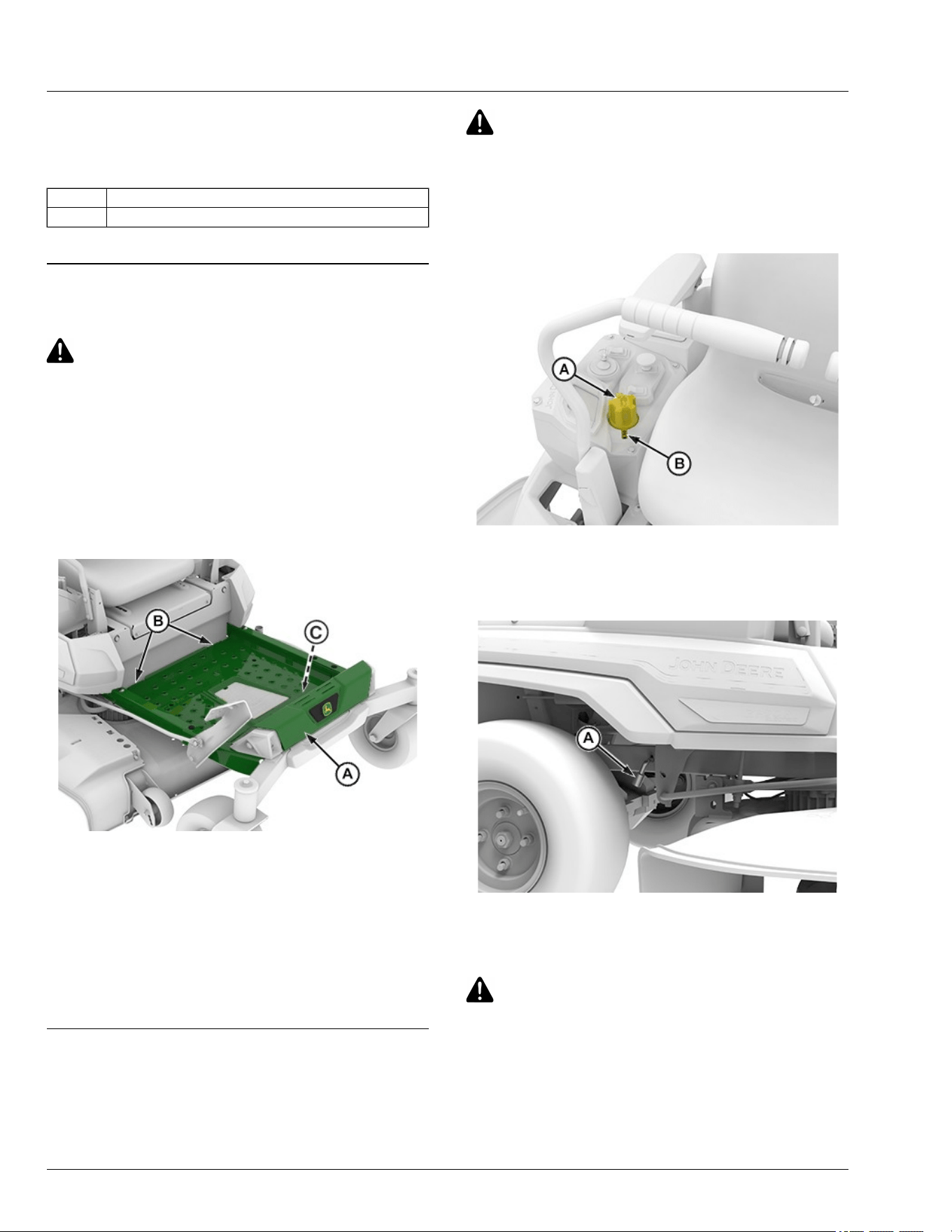
Mower Deck Identication
Mower decks in the following instructions are identied
by a code designation. The codes are as follows:
Code Description
42-IN 42—inch Accel Deep
GVG6119,1752248156831-19-11JUL25
Remove and Install Mower Deck Foot Plate
CAUTION: Avoid injury! Always operate the
mower with the foot plate installed. Operating
with the foot plate removed can cause serious
injury.
Remove Foot Plate
1. Park machine safely. (See Parking Safely in the
Safety section.)
IMPORTANT: Avoid damage! Do not step on status
display (C).
APY564723—UN—17FEB23
2. Lift the front end of the foot plate (A).
3. Using both hands, pull the foot plate out of the two
openings (B) in the frame.
Install Foot Plate
1. Using both hands, position the foot plate (A) into the
two openings (B) in the frame.
2. Lower the foot plate until it rests securely in place.
vs70618,1664966819188-19-20FEB23
Remove Mower Deck (42-IN)
1. Park machine safely. (See Parking Safely in the
Safety section.)
CAUTION: Avoid injury! Rotating blades are
dangerous.
Before adjusting or servicing mower:
● Remove the key pin next to the power button.
● Always wear gloves when handling mower
blades or working near blades.
APY564722—UN—17FEB23
2. Press the lift pedal and rotate the height-of-cut dial
(A) in clockwise direction to the lowest range in
index mark (B) to lower deck to 1.25 in height-of-cut
for lockout position.
APY571654—UN—23MAR23
3. Use the tracking adjustment socket (A) found in the
glove box to lock the lift system when removing the
deck.
CAUTION: Avoid Injury! Deck lift system is
spring-assisted and under tension. Injury can
occur if spring-assisted lift system is released
suddenly.
NOTE: Use of the tracking adjustment socket restrains
the lift spring from rotating the rockshaft.
Service Mower
55-1
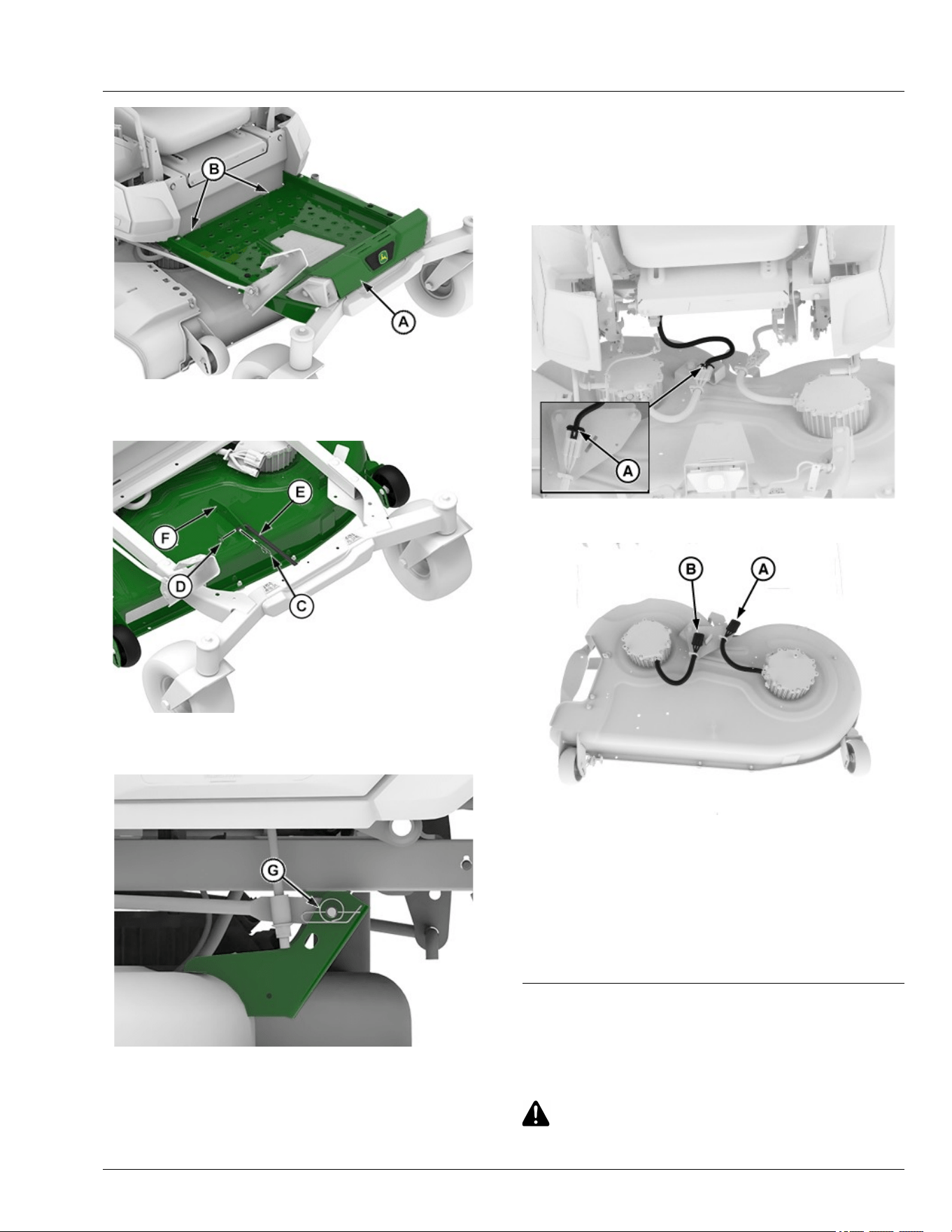
APY545218—UN—13SEP22
4. Lift the front end of the foot plate (A) and remove the
foot plate from the slots (B).
APY592568—UN—26SEP23
5. Remove locking pin (C), washer (D) and front lift
arm (E) from the front deck bracket (F).
APY545219—UN—13SEP22
42-IN Mower Deck Left Side Shown
6. Remove spring pin (G) from each side of the rear
mower bracket.
7. Rotate front caster wheels to maximize clearance.
NOTE: To disconnect connector (A), slide out the red
lock mechanism.
IMPORTANT: Avoid water coming into contact with
disconnected connectors.
MX674280—UN—19JUN25
8. Lift the lock (A), then disconnect the connector.
MX674281—UN—20JUN25
9. Disconnect both wire harness connectors (A) and
(B).
10. Slide the mower out from the machine. Do not
operate the machine without the mower deck.
Machine may become unstable without the mower
deck attached. Move machine only by hand. (See
Move Machine by Hand in Daily Operation section.)
SDHTXN6,1750160760597-19-08JUL25
Install Mower Deck (42-IN)
1. Park machine safely. (See Parking Safely in the
Safety section.)
CAUTION: Avoid injury! Rotating blades are
dangerous.
Service Mower
55-2
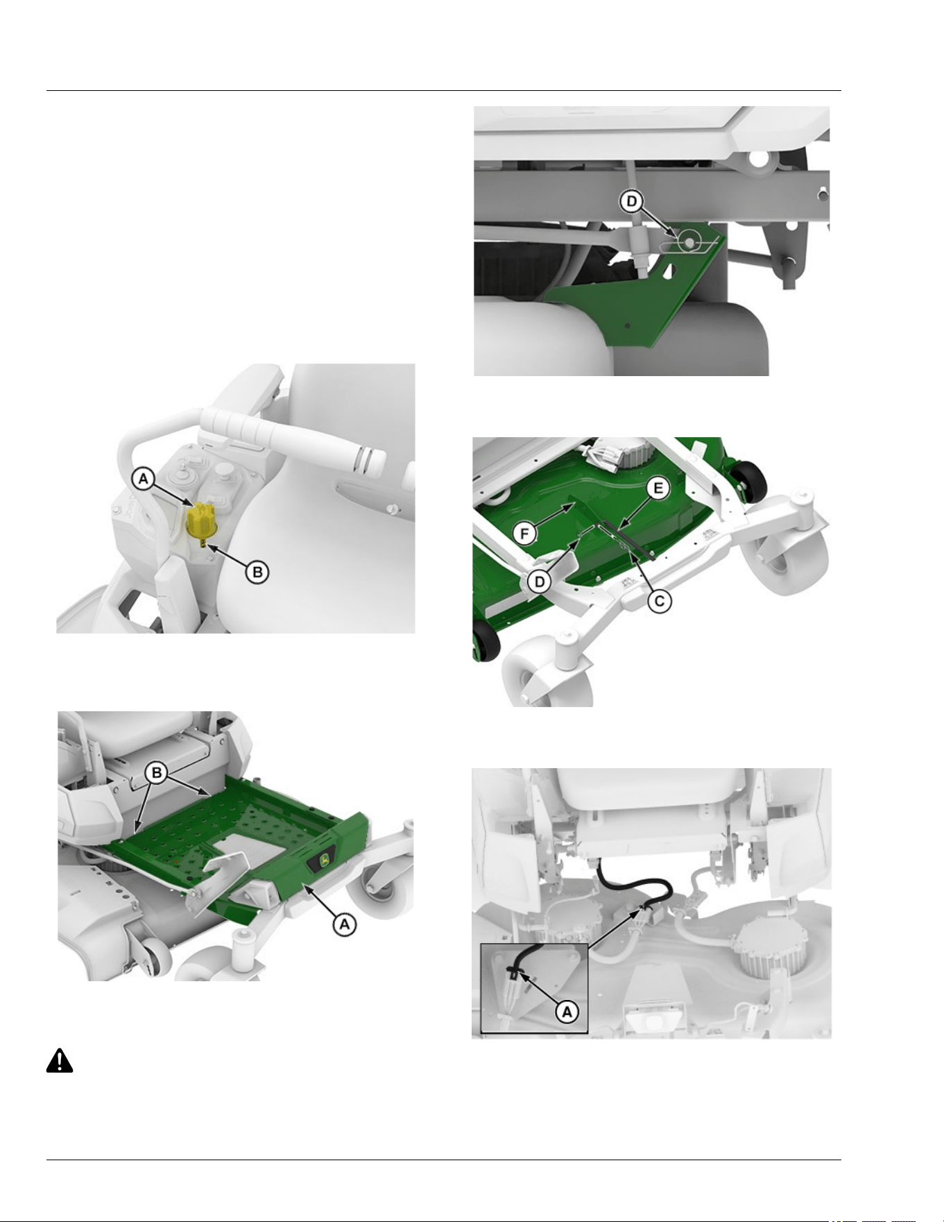
Before adjusting or servicing mower:
● Remove the key pin next to the power button.
● Always wear gloves when handling mower
blades or working near blades.
2. Rotate the height-of-cut dial counterclockwise
direction and press the lift pedal to lock in raised
position.
3. Slide mower deck under machine.
NOTE: Remove the tracking adjustment socket used for
lift system before installation of mower deck.
APY564722—UN—17FEB23
4. Rotate the height-of-cut dial (A) clockwise direction
to the lowest range in index mark (B) to lock deck in
lowered position.
APY545221—UN—13SEP22
5. Lift the front end of the foot plate (A) and remove the
foot plate from the slots (B).
CAUTION: Avoid Injury! Deck lift system is
spring-assisted and under tension. Injury can
occur if spring-assisted lift system is released
suddenly.
APY545222—UN—13SEP22
6. Install spring pin (D) onto each side of the rear
mower bracket.
APY592568—UN—26SEP23
7. Install front lift arm (E) onto the front deck bracket
(F) and secure with washer (D) and locking pin (C).
MX674280—UN—19JUN25
8. Connect the connector (A).
Service Mower
55-3
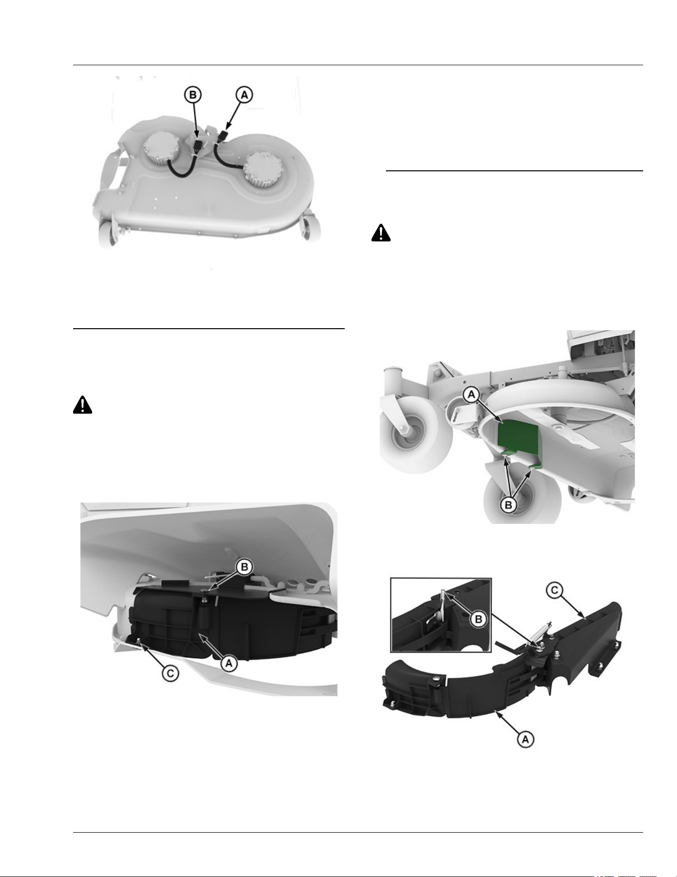
MX674281—UN—20JUN25
9. Connect both wire harness connectors (A) and (B).
10. Install foot plate.
SDHTXN6,1750160873127-19-08JUL25
Install MulchControl Discharge Plate (If
Equipped)
CAUTION: Avoid injury! Machine component or
attachment is heavy. Use a safe lifting device or
get an assistant to help lift, install, or remove
component or attachment.
NOTE: For ease of installation, place mower deck in the
vertical position.
APY564718—UN—16FEB23
42-IN Deck Shown
1. Position discharge plate (A) as shown.
2. Insert M8 x 20 carriage bolt (B) through the mower
deck and into the hole in the discharge plate.
3. Install M8 lock nut on bolt (B). Do not tighten yet.
4. Insert M8 shoulder bolt (C) through the discharge
plate and into the hole in the mower deck.
5. Install M8 lock nut on bolt (C).
6. Tighten nuts.
Specication
Lock Nut—Torque. . . . . . . . . . . . . . . . . . . . . . . . . . . . . . . . 20 N·m
(15 lb·ft)
GVG6119,1752248520524-19-11JUL25
Install MulchControl Deector (If Equipped)
CAUTION: Avoid injury! Machine component or
attachment is heavy. Use a safe lifting device or
get an assistant to help lift, install, or remove
component or attachment.
NOTE: For ease of installation, place mower deck in the
vertical position.
APY571655—UN—24MAR23
1. Remove the existing deector (A) by removing bolts
(B) prior to install MulchControl deector.
APY551599—UN—08NOV22
Service Mower
55-4
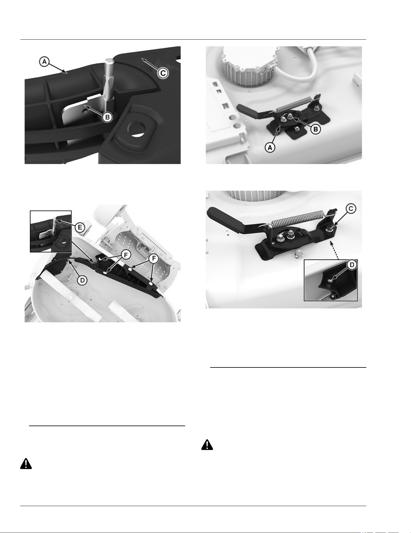
APY551600—UN—16FEB23
42-IN Deck Shown
2. Assemble kit gate (A) and bae (C) together as
shown and insert the pin (B) in the slots.
APY564719—UN—16FEB23
42-IN Deck Shown
3. Install right deector assembly (D) to the mower deck
using M8 shoulder bolts (F) and M8 nuts.
4. Ensure the pin (E) is in the correct slot and that the
gate door can open and close.
5. Tighten lock nuts.
Specication
Lock Nut—Torque. . . . . . . . . . . . . . . . . . . . . . . . . . . . . . . . 20 N·m
(15 lb·ft)
GVG6119,1752248616130-19-11JUL25
Install MulchControl Handle (If Equipped)
CAUTION: Avoid injury! Machine component or
attachment is heavy. Use a safe lifting device or
get an assistant to help lift, install, or remove
component or attachment.
APY551596—UN—07JUL25
1. Install handle assembly (A) to hinge pin with a M8
lock nut (B). Tighten lock nut until snug on handle.
APY551597—UN—09FEB23
2. On the top side of deck, install M8 lock nut (C) on the
shoulder bolt (D) to secure handle assembly.
Specication
Lock Nut—Torque. . . . . . . . . . . . . . . . . . . . . . . . . . . . . . . . 20 N·m
(15 lb·ft)
gh8xt3t,1668074852710-19-19APR24
Remove and Store MulchControl (If
Equipped)
Remove MulchControl
1. Remove the mower deck. (See Removing Mower
Deck in this section of the manual.)
CAUTION: Avoid injury! Blades are sharp.
Always wear gloves when handling blades or
working near blades. Replace blades if
defective. Never straighten or weld them.
2. Remove mulch blades.
Service Mower
55-5
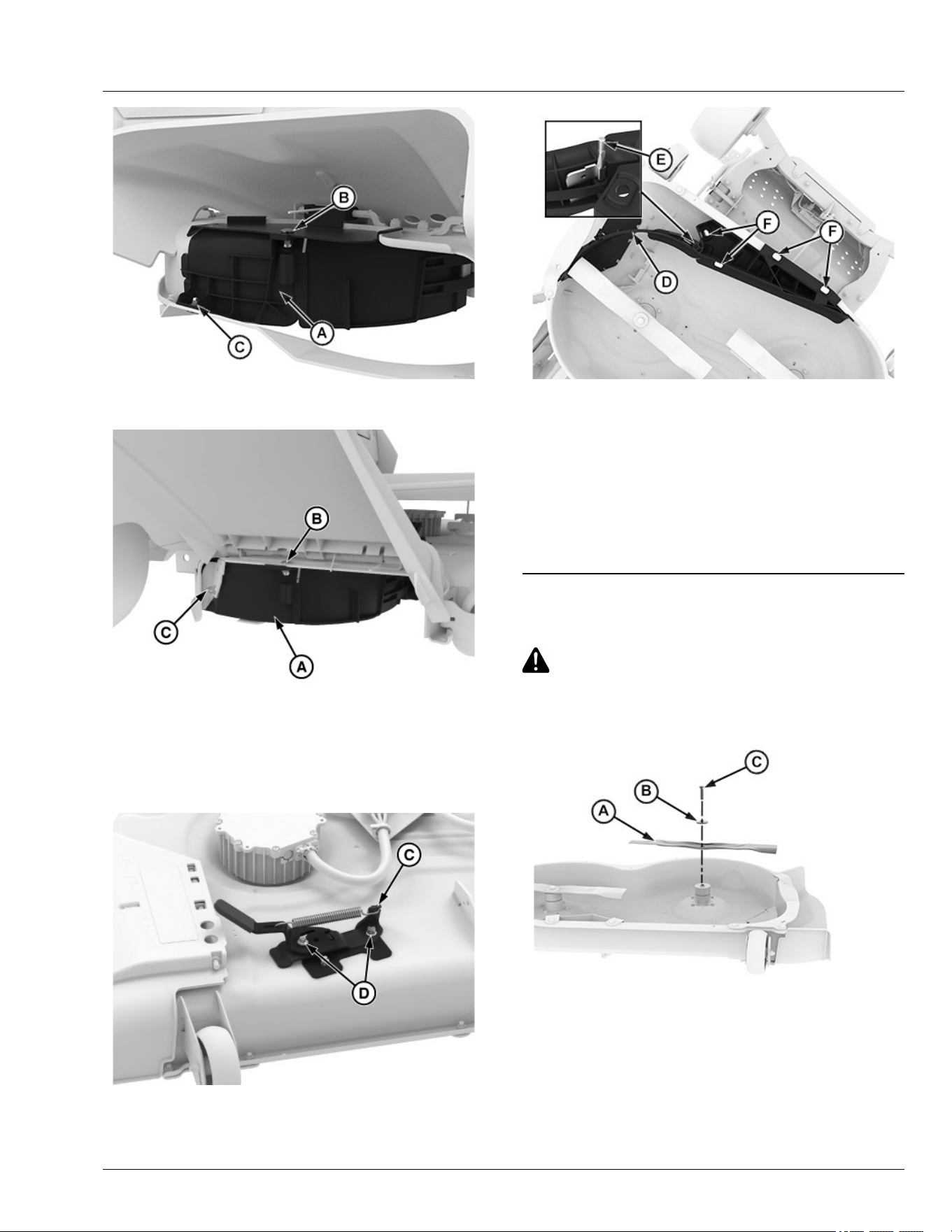
APY564718—UN—16FEB23
42-IN Deck Shown
APY600494—UN—09NOV23
42-IN Deck Shown
3. Remove discharge plate (A) from discharge area by
removing the hex ange bolts (C) and hex ange
nuts (B).
APY556344—UN—07JUL25
4. Loosen nuts (D) and remove the handle assembly
(C).
APY564719—UN—16FEB23
42-IN Deck Shown
5. Loosen shoulder bolts (F) and remove M8 nuts, then
remove the left-hand side deector assembly (D)
remove the pin (E) from the slots.
Store MulchControl
Clean and store all MulchControl parts in a clean, dry
place.
GVG6119,1752248328496-19-11JUL25
Install Mulch Blades
CAUTION: Avoid injury! Blades are sharp.
Always wear gloves when handling blades or
working near blades. Replace blades if
defective. Never straighten or weld them.
APY545223—UN—13SEP22
1. Install blade (A) with cutting edge toward the ground.
2. Install large washer (B) and bolt (C).
Service Mower
55-6
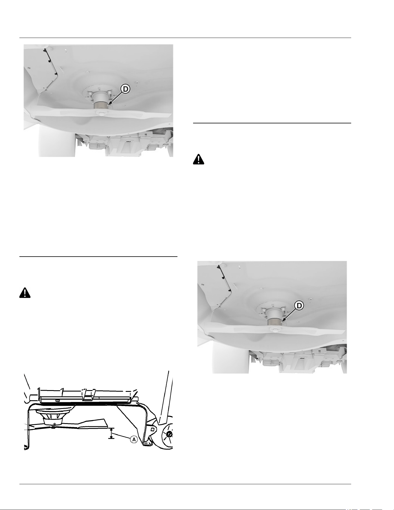
APY564707—UN—15FEB23
3. Hold a wrench at slot (D) or insert wood block
between blade and mower to prevent the blade from
turning when tightening bolt.
4. Tighten bolt.
Specication
Bolt—Torque. . . . . . . . . . . . . . . . . . . . . . . . . . . . . . .. . . . . 68 N·m
(50 lb·ft)
5. To check blade-to-mulch bae clearance, rotate
blades by hand. If interference occurs, check that
hardware is tightened.
vs70618,1664967539700-19-11JUL25
Checking for Bent Mower Blades
CAUTION: Avoid Injury! Blades are sharp.
Always wear gloves when handling blades or
working near blades.
Replace blades if defective. Never straighten or
weld them.
1. Park machine safely. (See Parking Safely in the
Safety section.)
2. Raise mower deck to highest position to access
blades.
MXAL42867—UN—09APR13
Mower deck with side discharge used for illustration
3. Measure distance (A) between blade tip and at
ground surface.
4. Rotate blade 180° and measure distance between
other blade tip and at ground surface.
5. Install new blade if the dierence between the two
measurements is more than 3 mm (1/8 in).
6. Repeat for all blades.
MP47322,00F466C-19-12JAN23
Service Mower Blades
CAUTION: Avoid injury! Rotating blades are
dangerous.
Before adjusting or servicing mower:
● Remove the key pin next to power button.
● Always wear gloves when handling mower
blades or working near blades.
Remove Mower Blades
1. Park machine safely. (See Parking Safely in the
Safety section.)
2. Raise mower deck to gain access to mower blades. If
necessary, remove mower deck.
APY564707—UN—15FEB23
3. Hold a wrench at slot (D) or insert wood block
between blade and mower to prevent the blade from
turning when removing bolt.
Service Mower
55-7
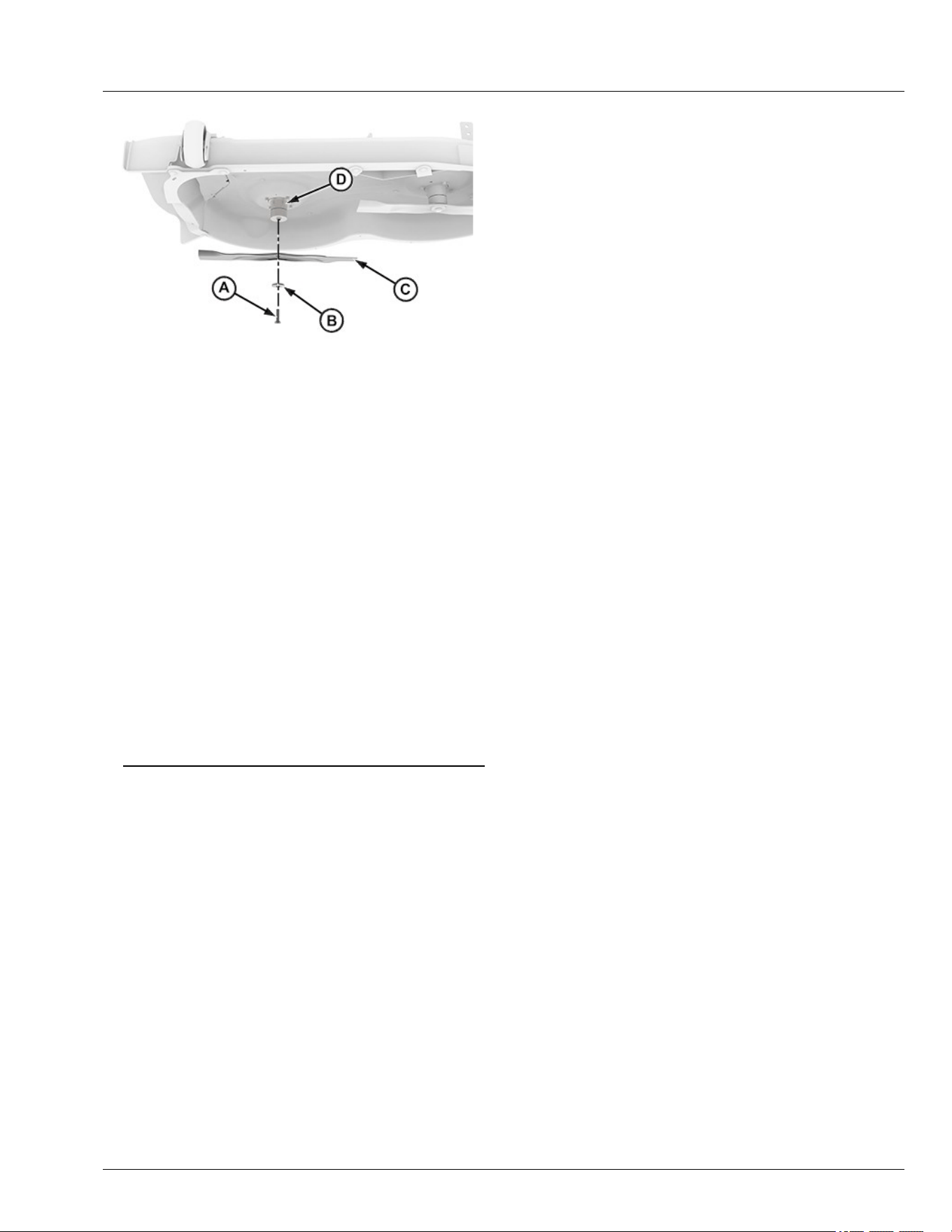
APY545224—UN—13SEP22
4. Remove bolt (A), washer (B), and blade (C) from
spindle (D).
5. Inspect blades. Sharpen, balance or replace blades
as necessary.
Install Mower Blades
1. Make sure the blade (C) is seated properly between
mower spindle (D) and washer (B).
2. Position mower blade (C) with cutting edge toward
ground onto mower spindle.
3. Install washer (B) with cupped side towards blade,
and bolt (A) to secure blade onto spindle shaft.
4. Hold a wrench at slot (D) or insert wood block
between blade and mower to prevent the blade from
turning when tightening bolt.
Specication
Bolt—Torque. . . . . . . . . . . . . . . . . . . . . . . . . . . . . 68 N·m (50 lb·ft)
gh8xt3t,1699421712199-19-11JUL25
Service Mower
55-8
Battery
CAUTION: Avoid Injury! If the battery has been
submerged in water, do not attempt to start the
machine. Keep the machine at least 50 feet
away from combustible materials and contact
your service provider for assistance.
NOTE: For battery service, replacement, and disposal
contact your service provider.
Maintenance
CAUTION: When servicing, use only identical
Deere replacement parts. Use of any other parts
may create a hazard or cause product damage.
CAUTION: Do not at any time let brake uids,
gasoline, petroleum-based products,
penetrating oils, etc., come in contact with
plastic parts. Chemicals can damage, weaken,
or destroy plastic, which may result in serious
personal injury.
CAUTION: To reduce the risk of re, personal
injury, and product damage due to a short
circuit, never immerse your tool, battery pack,
or charger in uid or allow uid to ow inside
them. Corrosive or conductive uids, such as
seawater, certain industrial chemicals, and
bleach or bleach-containing products etc., can
cause a short circuit.
GVG6119,1748235796507-19-16JUL25
Decommissioning — Proper Recycling and
Disposal of Fluids and Components
TS1133—UN—15APR13
Safety and environmental stewardship measures must
be taken into account when decommissioning a
machine and/or component. These measures include
the following:
● Use appropriate tools and personal protective
equipment such as clothing, gloves, face shields or
glasses, during the removal or handling of objects
and materials.
● Follow instructions for specialized components.
● Release stored energy by lowering suspended
machine elements, relaxing springs, disconnecting
the battery or other electrical power, and releasing
pressure in hydraulic components, accumulators,
and other similar systems.
● Minimize exposure to components which may have
residue from agricultural chemicals, such as
fertilizers and pesticides. Handle and dispose of
these components appropriately.
● Carefully drain engines, fuel tanks, radiators,
hydraulic cylinders, reservoirs, and lines before
recycling components. Use leak-proof containers
when draining uids. Do not use food or beverage
containers.
● Do not pour waste uids onto the ground, down a
drain, or into any water source.
● Observe all national, state, and local laws,
regulations, or ordinances governing the handling or
disposal of waste uids (example: oil, fuel, coolant,
brake uid); lters; batteries; and, other substances
or parts. Burning of ammable uids or components
in other than specially designed incinerators may be
prohibited by law and could result in exposure to
harmful fumes or ashes.
● Service and dispose of air conditioning systems
appropriately. Government regulations may require a
certied service center to recover and recycle air
conditioning refrigerants which could damage the
atmosphere if allowed to escape.
● Evaluate recycling options for tires, metal, plastic,
glass, rubber, and electronic components which may
be recyclable, in part or completely.
● Contact your local environmental or recycling center,
or your John Deere dealer for information on the
proper way to recycle or dispose of waste.
DX,DRAIN-19-01JUN15
Service Electrical
60-1

Lithium-Ion Batteries - No Serviceable Parts
DX561226B—UN—17FEB23
GVG6119,1748325617800-19-27MAY25
Service Electrical
60-2
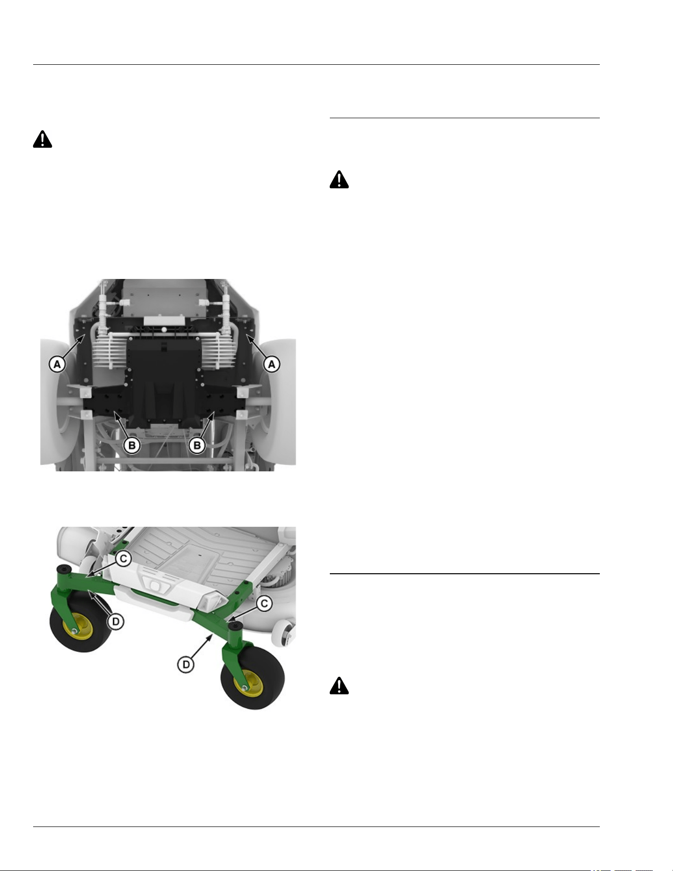
Lift Machine
1. Park machine safely. (See Parking Safely in the
Safety section.)
CAUTION: Avoid injury! The machine can fall or
slip from an unsafe lifting device or supports.
● Use a safe lifting device rated for the load to
be lifted.
● Lower machine onto jackstands or other
stable supports and block wheels before
servicing.
NOTE: Remove any material collection system
attachments prior to lifting machine.
GX675600—UN—07JUL25
2. Safely lift rear of machine frame points (A). Place
jackstands or other stable supports onto transaxle
locations (B).
APY551595—UN—08NOV22
3. Safely lift front of machine at machine frame points
(C). Place jackstands or other stable supports onto
machine frame locations (D).
4. If lifting only the front of machine, block rear wheels
remaining on ground to avoid movement of machine.
5. To lower the machine, lift front and/or rear of
machine, and remove jackstands or supports. Lower
the machine.
GVG6119,1751859999101-19-07JUL25
Checking Tire Pressure
CAUTION: Avoid injury! Explosive separation of
tire and rim parts is possible when they are
serviced incorrectly:
● Do not attempt to mount a tire without the
proper equipment and experience to perform
the job.
● Make sure that all tires are inated to the
recommended pressure, especially when
operating on slopes. Low pressure can
cause machine to become unstable on
slopes.
● Do not weld or heat a wheel and tire
assembly. Heat can cause an increase in air
pressure resulting in an explosion. Welding
can structurally weaken or deform the wheel.
● Do not stand in front or over the tire
assembly when inating. Use a clip-on chuck
and extension hose long enough to allow
you to stand to one side.
1. Check tires for damage.
2. Check tire pressure with an accurate low-pressure
gauge.
3. A lower pressure will improve traction and
performance depending on turf conditions or if
transport areas have steep inclines.
4. Add or remove air to meet specied tire pressure.
(See Specications section for recommended tire
pressures.)
MP47322,00F4677-19-10JUN20
Remove and Install Wheel Assembly
Remove
1. Park machine safely. (See Parking Safely in the
Safety section.)
CAUTION: Avoid injury! The machine can fall or
slip from an unsafe lifting device or supports.
● Use a safe lifting device rated for the load to
be lifted.
● Lower machine onto jackstands or other
stable supports and block wheels before
servicing.
Service Miscellaneous
65-1
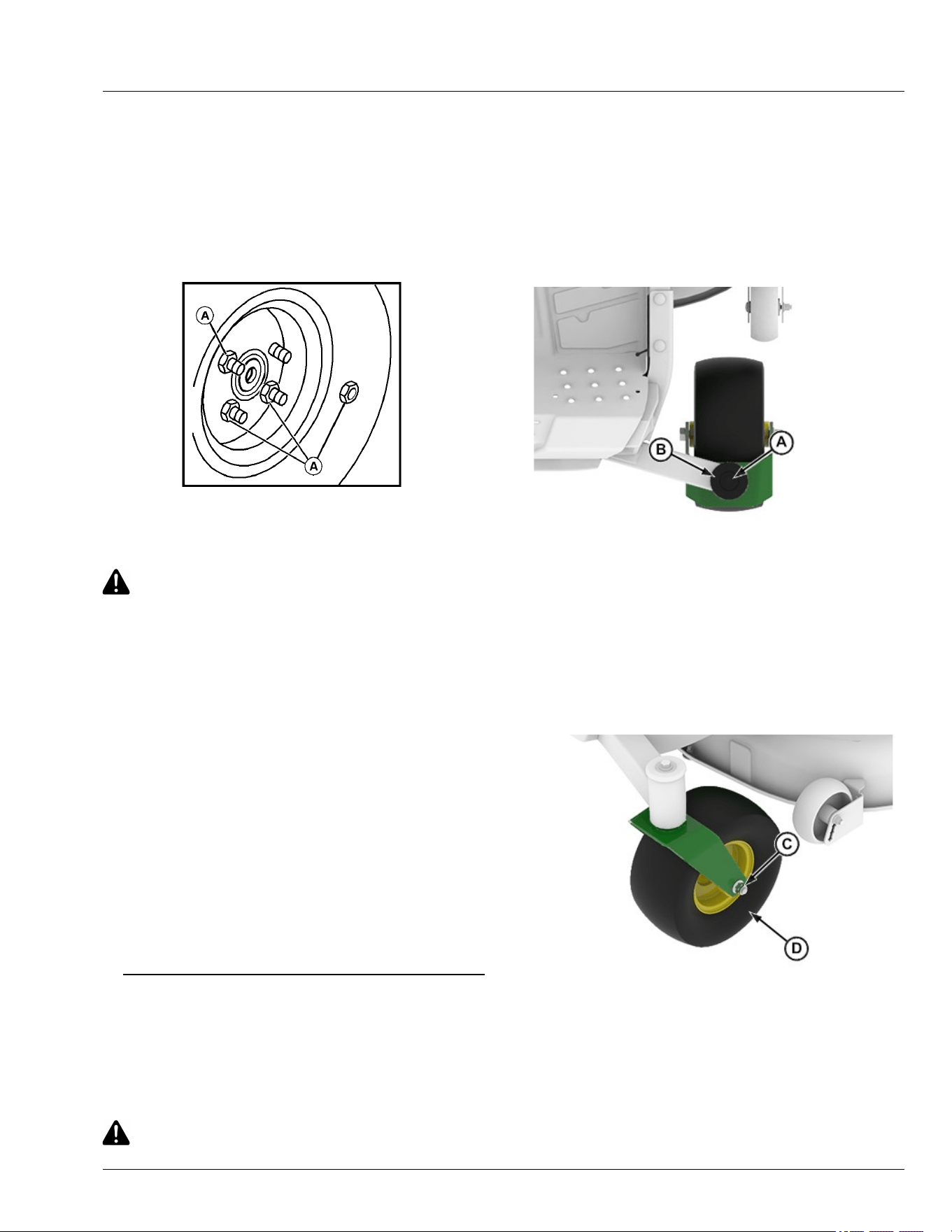
IMPORTANT: Avoid damage! Place jackstands
under frame, not under transmission or battery
mounting bracket, when raising or supporting
machine.
2. Raise machine with a safe lifting device and lower
machine onto jack stands or other stable supports.
Block wheels remaining on the ground to prevent
machine movement.
MXAL42875—UN—09APR13
3. Remove wheel nuts (A).
4. Remove the wheel assembly.
CAUTION: Avoid injury! Explosive separation of
tire and rim parts is possible when they are
serviced incorrectly:
Do not attempt to mount a tire without the
proper equipment and experience to perform
the job.
5. Take wheel assembly to your service provider for
repairs.
Install
1. Install wheel assembly with valve stem to the
outside.
2. Tighten wheel nuts evenly in alternating sequence
until snug.
3. Lower machine completely to the ground.
4. Tighten wheel nuts to specication.
Specication
Wheel Nut—Torque. . . . . . . . . . . . . . . . . . . . . . . 102 N·m (75 lb·ft)
gh8xt3t,1668691504411-19-16JUL25
Remove and Install Front Caster Wheels
Remove:
1. Park machine safely. (See Park Machine Safely in
the Safety section.)
CAUTION: Avoid injury! The machine can fall or
slip from an unsafe lifting device or supports.
● Use a safe lifting device rated for the load to
be lifted.
● Lower machine onto jackstands or other
stable supports and block wheels before
servicing.
NOTE: Remove all attachments prior to lifting machine.
2. Jack up front of machine and place on safety stands.
APY545227—UN—13SEP22
3. Support caster assembly and remove ange bolt (A)
and cap (B).
4. Remove caster from machine.
5. Inspect bearings at top and bottom of frame. Replace
worn or damaged bearings.
NOTE: Inner race extends above outer race.
APY545228—UN—13SEP22
6. Remove lock nut (C) and pull bolt out of caster.
7. Remove wheel assembly (D).
Service Miscellaneous
65-2
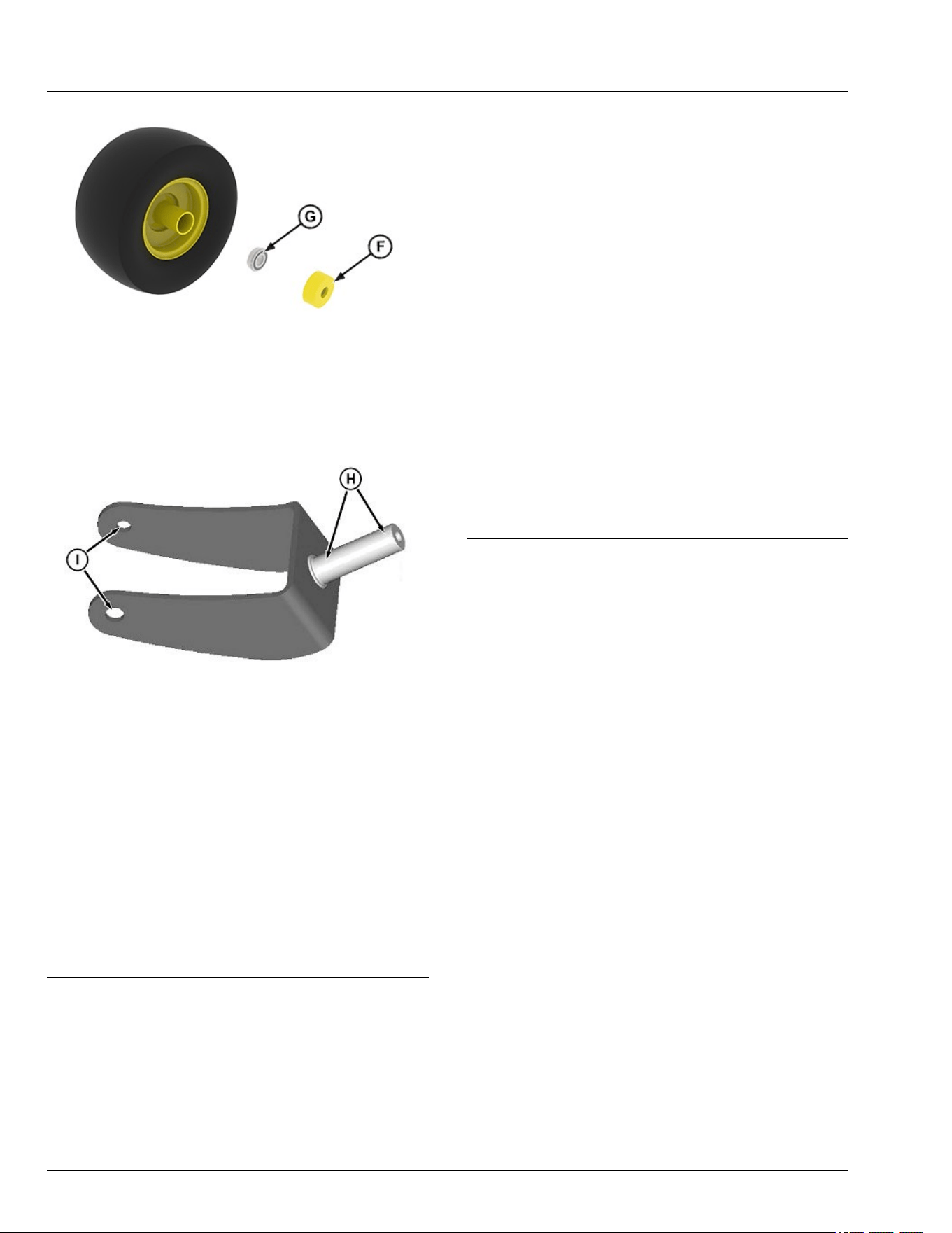
APY545229—UN—13SEP22
8. Remove shield (F) and bearing (G). Inspect shields,
wheel, and bearings for wear or damage. Replace
worn or damaged parts.
GXT002156—UN—02JUN15
9. Inspect bearing wear areas (H), and bolt holes (I) for
wear or damage. Replace if necessary.
Install
● Apply grease to caster shaft and bolt.
● Assemble in the reverse order of disassembly.
● Tighten caster lock nut and bolt to specication.
Specication
Lock Nut—Torque. . . . . . . . . . . . . . . . . . . .. . . . . 47 N·m (35 lb·ft)
● Tighten ange bolt securing yoke to specication.
Specication
Bolt—Torque. . . . . . . . . . . . . . . . . . . . . . . . . . . . 47 N·m (35 lb·ft)
vs70618,1664967918900-19-12JAN23
Cleaning and Repairing Metal Surfaces
Cleaning:
Follow automotive practices to care for your vehicle’s
painted metal surfaces. Use a high-quality automotive
wax regularly to maintain the factory look of your
vehicle’s painted surfaces.
Repairing Minor Scratches (surface scratch):
1. Clean area to be repaired thoroughly.
IMPORTANT: Avoid damage! Do not use rubbing
compound on painted surfaces.
2. Use automotive polishing compound to remove
surface scratches.
3. Apply wax to entire surface.
Repairing Deep Scratches (bare metal or primer
showing):
1. Clean area to be repaired with rubbing alcohol or
mineral spirits.
2. Use paint stick with factory-matched colors available
from your service provider to ll scratches. Follow
directions included on paint stick for use and for
drying.
3. Smooth out surface using an automotive polishing
compound. Do not use power buer.
4. Apply wax to surface.
MP47322,00F467A-19-16JUL25
Service Miscellaneous
65-3
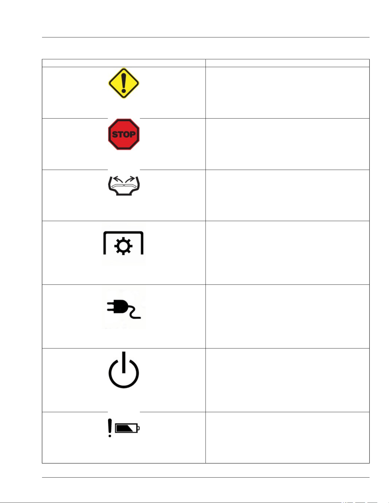
Icons and Denitions
Icons Denitions
GX675589—UN—03JUL25
Caution Indicator
Indicates that one or more functions or systems on the machine are
operating outside normal parameters in such a way as to require
attention or further monitoring of the function or system, but not
necessarily to require shutting down the machine or equipment.
GX675595—UN—03JUL25
Machine Stop
Indicates to the operator that the machine as stopped due to a critical
issue.
APY556355—UN—07JUL25
Stick Indicator
Flashing Sticks—Return sticks to the outward park position to clear
fault.
APY556350—UN—06DEC22
PTO-Power Take-O
Solid PTO—Power Take-O (PTO) is ON.
APY600493—UN—08NOV23
Charger Indicator
Solid Charger-DC power source is connected.
Flashing Charger-
● The operator is attempting to press and hold the Push Button to shut
down the machine while the charger is still connected.
● The charger must be connected if the indicator is ashing during
operation.
APY600492—UN—08NOV23
Flashing Power Button (PBS)
Flashing Power Button (PBS)–Indicates that the Push Button must be
pressed to place the machine in the Armed State or to restart the vehicle
and clear the fault.
GX669598—UN—03JUL25
Battery Attention
System detected a fault related to the battery management system.
Troubleshooting
70-1

GX669600—UN—27MAY25
Low Temperature Alert
Indicates a low temperature fault has been detected in one or more
system components.
GX669599—UN—27MAY25
High Temperature Alert
Indicates a high temperature fault has been detected in one or more
system components.
GX669597—UN—27MAY25
LoadMatch™
Optimizes machine performance under heavy load conditions.
GX669606—UN—27MAY25
State of Charge Percentage
Indicates State of Charge.
GX669601—UN—27MAY25
Battery Presence
Shows available battery packs present in the machine and their current
locations.
GX669602—UN—27MAY25
Battery Status
Red Ring Behavior:
● Elevated temperature—solid red ring.
● Under temp—ash red ring.
● low voltage—ash red ring.
● Over voltage—ash red ring.
● Over current—ash red ring.
Troubleshooting
70-2

GX669605—UN—27MAY25
Vehicle Hourglass
Indicates the number of vehicle hours.
GX669607—UN—27MAY25
Motor Indicator
Indicates potential issues with one of the electrical drives.
GVG6119,1748237857199-19-16JUL25
Using Troubleshoot Chart
If you are experiencing a problem that is not listed in this chart, see your Technical Manual or your service provider.
NOTE: The mower is designed with software that
monitors power demands from the mower blades
and wheel motors. In certain mowing conditions,
the power needed from operator inputs and mowing
conditions may surpass machine limits. When this
happens, the machine will lower travel speed to
allow the mower to keep operating with blades
engaged. To minimize the chances of this
happening, adjust mowing behavior by increasing
the height of cut to reduce the amount of grass
being cut, slowing down travel speed, or changing
the operating mode to Hi or Lo instead of bagging
mode.
gh8xt3t,1702968265126-19-10JUL25
Battery—Troubleshooting
Problem Cause Solution
The battery pack charge is reduced after more
than one month of non-use.
The battery pack has automatically performed
self-maintenance to extend its life.
Fully recharge the battery pack before use.
The battery endcap gets warm during storage.
Either 5 LEDs shine solid red for 10 seconds,
then go out and remain o for 10 second, then
shine solid red for 10 seconds, or the 5 LEDs
ash green for every two seconds. This
dierence is based on battery version.
The battery pack is automatically performed
self-maintenance to extend battery life. The
LEDs will run the cycle until the self-
maintenance is nished.
No action is required; this is normal.
The 5-LED indicator shines red when the
battery pack is working.
The battery is too hot. Cool the battery pack until its temperature
drops below 152°F (67°C).
The battery will not charge correctly on the
charger. (The charger does not work and
shines the cold/heat battery indicator).
The battery pack is too hot or too cold. Allow the battery pack to cool down or warm
up. If charging does not restart when the
battery pack returns to the normal temperature,
reinsert the battery pack.
Troubleshooting
70-3

Signicantly reduced run time after fully
charging the battery pack.
Batteries are near the end of their usable life. Replace battery pack.
GVG6119,1748240715606-19-09JUN25
Charger—Troubleshooting
Problem Cause Solution
Charger doesn't work. Three
LED indicators are shining
solid red.
Battery pack or charger error. Try charging a dierent battery pack.
Reset the charger by unplugging the charger from the power supply
and waiting until the LED indicators go out, then reconnect the plug to
the power supply.
If none of the above solves the problem, call your service provider.
Charger doesn't work and the
rst LED indicator ashes
green.
Battery pack is too hot or too cold. Allow the battery pack to reach normal temperature. Charging will
begin when the battery pack returns to the normal temperature range
of 37°F (3°C) – 135°F (57°C).
Charger does not work and the
rst LED indicator ashes red.
The charger’s fan is blocked or
damaged.
Unplug the charger, shake the charger slightly, and then reconnect
the charger between the power supply and the mower to see whether
the charger fan works normally. If it does not work, call your service
provider.
Charger does not work and all
LED indicators are o.
Bad connection between the battery
pack and the mower.
Charger malfunction.
Try to remove and reinsert the battery pack in the mower.
Unplug the charger and then reconnect the plug to the power supply.
If it does not work, call your service provider.
GVG6119,1749659402430-19-16JUL25
Electrical
IF CHECK
Machine will not power on Batteries are not charged.
Not enough batteries installed.
Battery not fully inserted into the machine.
Defective power button.
Key pin not fully inserted.
Machine will not go to armed
state
Mower engagement switch is engaged.
Park brake is not locked with the motion control levers in the Start/Shutdown Position.
Not enough batteries installed.
Ensure operator is in seat and seat switch is operating correctly.
Battery not fully inserted into the machine.
Battery does not charge Blown internal battery fuse.
Check charging cord for damage.
Charger improperly connected.
Battery in fault condition.
Damage to charge port.
Tripped breaker on supply circuit.
Supply voltage too low.
Lights do not work Lights do not work while the charger is plugged in.
GVG6119,1751358431968-19-16JUL25
Machine
IF CHECK
Machine vibrates too much or rattles excessively Mower blades not balanced.
Machine does not move with machine powered On Check if Push Mode switch ON.
Check to See if machine is connected to charger.
Front of machine squeaks while driving Lubricate mower front draft rod at front and rear pivot points.
Troubleshooting
70-4

IF CHECK
Machine will not go into armed state Not enough batteries installed.
GVG6119,1751370518180-19-16JUL25
Mower Deck
IF CHECK
Discharge chute clogged Travel speed too fast.
Grass too long.
Grass too wet.
Machine at low mow mode.
Restricted air ow.
Adjust cutting height to remove only 1/3 of grass at a time.
Patches of grass uncut Travel speed too fast.
Mower deck needs cleaning.
Too much vibration Blades out of balance.
Blades scalping grass Cutting too low.
Mower wheels not adjusted correctly.
Turning speed too fast.
Ridges in terrain.
Rough or uneven terrain.
Low tire pressure.
Mower travel speed slows while
mowing
Check travel speed mode.
Increase cut height to remove less grass.
If in Bagging Mode, reduce blade speed by switching to Low Mode or Hi Mode.
Uneven cut Mower deck not leveled properly.
Travel speed too fast.
Blades dull.
Mower wheels not adjusted Correctly.
Tire pressure unequal.
Adjust cutting height to remove only 1/3 of grass at a time.
Excessive clippings are expelled
from front of mower deck
Conditions may be too dry or terrain too uneven to provide good seal between front of deck and grass. Contact
your provider to purchase dry condition kit.
Mower cut quality or power is not
acceptable for grass conditions
Change mode to Bagging Mode for increased blade speed.
gh8xt3t,1715692595169-19-16JUL25
MulchControl (If Equipped)
IF Check
MulchControl gate will not open Clogging of mower deck/baes.
MulchControl gate will not close Clogging of mower deck/baes.
MulchControl gate not holding setting (open or
closed)
Check for handle seated rmly onto pin taper and properly aligned.
MulchControl causing blowout in closed position Check that gate stop is installed (after removal of cut and throw 42–inch Accel Deep only).
Ensure that system is in closed position.
MulchControl material dispersion not Satisfactory Clean debris buildup from underside of deck.
Check blades for sharpness and damage.
Ensure that correct blades are installed (MulchControl is designed to use mulch blades, not
standard blades).
Change blades.
Check discharge chute for damage.
Check procedures on adjusting mower. Level side-to-side and front-to-rear.
Adjust system for proper door position.
Mowing too fast for grass conditions.
gh8xt3t,1668075813877-19-10JUL25
Troubleshooting
70-5

PTO Switch
IF Cause Check
PTO not running when mower engagement
switch pulled
Software disables the ability to activate the
PTO due to a spindle motor fault or other
unsafe operating conditions.
mower has entered Go Home Mode.
Cycle PTO or turn machine OFF and ON.
Charge battrey or put in battery pack with
higher SOC.
Low battery bars ash Low battery Charge machine.
GVG6119,1751370686569-19-16JUL25
Fault Table (E-Codes)
NOTE: The table contains only faults that trigger e-
codes.
Error code with a prex to designate the fault subsystem
type.
● E1XXX– E1 indicates ‘Battery’ and XXX is the error
code.
● E2XXX – E2 indicates ‘Vehicle Controller’ and XXX is
the error code.
● E4XXX – E4 indicates ‘Inverter’ and XXX is the error
code.
- E44XX – Left traction Motor
- E45XX – Right traction Motor
- E41XX – Left Spindle Motor
- E42XX – Center Spindle Motor
- E43XX – Right Spindle Motor
E-Code Number SPN FMI Fault Name Operator Action
E1204 5919 16
Battery Pack Faulted-Pack Over
Voltage
Disconnect vehicle from charger and restart
vehicle. If problem persists, replace battery.
E1209 5919 18
Battery Pack Faulted-Pack Under
Voltage
Connect vehicle to the charger.
E1211 5920 16
Battery Pack Faulted-Pack Over
Current
Restart vehicle. If problem persists, reduce
vehicle speed while mowing, turn o PTO, or
reduce battery load.
E1215 8104 16
Battery Pack Faulted-Pack Over
Temperature
Allow the pack to cool down. If the problem
persists, reduce vehicle speed while mowing,
turn o the PTO, reduce the PTO load, or insert
a cooler battery pack if available. Restart the
vehicle before resuming operation.
E1219 8104 18
Battery Pack Faulted-Pack Under
Temperature
Allow pack to warm up. A warmer battery pack
could be inserted if available. Restart vehicle
before resuming operation.
E1228 520960 9 Vehicle CAN Loss
Restart vehicle. If problem persists, contact
your authorized service provider.
E1233 8413 10 Precharge Fault
Restart vehicle. Attempt to unplug and then
plug charger back in to the vehicle.
E1235 9631 12 MCU Internal Fault
Restart vehicle. If problem persists, contact
your authorized service provider.
E1240 5920 13 Current Sensor Not Calibrated
Restart vehicle. If problem persists, contact
your authorized service provider.
E1255 639 14 CAN Bus O
Restart vehicle. If problem persists, contact
your authorized service provider.
E1258 5960 16 MOSFET Over Temperature
Let the battery pack(s) cool down before
resuming operation. If the problem persists,
reduce the load on the mower to aid in
temperature reduction.
E1259 9631 6 System Overcurrent
Restart vehicle. If problem persists, reduce
vehicle speed while mowing, turn o PTO, or
reduce electrical load on battery.
E1260 234 2
MCU Software Version Incompatible
Fault
Restart vehicle. If problem persists, contact
your authorized service provider.
E2003 518406 4
Right Traction Stick Circuit Voltage Low
or Shorted to Ground
Restart vehicle. If problem persists, inspect
Troubleshooting
70-6

right stick sensor interface connector and
circuit wiring.
E-Code Number SPN FMI Fault Name Operator Action
E2004 518406 8
Right Traction Stick Sensor Circuit
Frequency Abnormal Fault
Restart vehicle. If problem persists, inspect
right stick sensor interface connector and
circuit wiring.
E2005 518406 3
Right Traction Stick Circuit Voltage High
or Shorted to Power Source
Restart vehicle. If problem persists, inspect
right stick sensor interface connector and
circuit wiring.
E2006 518406 31
Right Traction Stick Sensor Channel A-
B Mismatch Fault
Restart vehicle. If problem persists, inspect
right stick sensor interface connector and
circuit wiring.
E2007 518407 3 Left Stick Sensor, Short to High
Restart vehicle. If problem persists, inspect left
stick sensor interface connector and circuit
wiring.
E2008 518407 4
Left Traction Stick Sensor Circuit
Voltage Low or Shorted to Ground
Restart vehicle. If problem persists, inspect left
stick sensor interface connector and circuit
wiring.
E2009 518407 8
Left Traction Stick Sensor Circuit
Frequency Abnormal Fault
Restart vehicle. If problem persists, inspect left
stick sensor interface connector and circuit
wiring.
E2010 518407 31
Left Traction Stick Sensor Channel A-B
Mismatch Fault
Restart vehicle. If problem persists, inspect left
stick sensor interface connector and circuit
wiring.
E2014 520874 31 Vehicle Software EOL Mismatch Fault
Restart vehicle. If problem persists, reprogram
controller.
E2015 520870 31 Vehicle Software EE Checksum Fault
Restart vehicle. If problem persists, reprogram
controller.
E2016 520871 31
Vehicle Software EE Non-Critical Data
Checksum Fault
Restart vehicle. If problem persists, reprogram
controller.
E2017 520872 31
Vehicle Software EE Critical Data
Checksum Fault
Restart vehicle. If problem persists, reprogram
controller.
E2019 524265 31 Vehicle Software EOL Checksum Fault
Restart vehicle. If problem persists, reprogram
controller.
E2024 518703 5 Battery CAN Communication Fault
Restart vehicle. If problem persists, inspect
battery CAN circuit wiring.
E2021 518702 5 Inverter Software Invalid Fault
Restart vehicle. If problem persists, reprogram
controller.
E2025 518408 4 Power Button Voltage Low
Restart vehicle. If problem persists, inspect
power button interface connector and circuit
wiring.
E2026 518408 3 Power Button Voltage High
Restart vehicle. If problem persists, inspect
power button interface connector and circuit
wiring.
E2028 639 14 Vehicle CAN Bus O Fault
Restart Vehicle. If problem persists, verify CAN
bus voltage and resistance.
E4(4/5) 15 517061 2 Inverter Multiple Phases Open Fault
Restart vehicle. If problem persists, inspect
motor 3 phase circuit wiring.
E4(4/5) 18 517061 4 Inverter Phase Shorted to Ground Inspect motor 3 phase circuit wiring.
E4(4/5) 19 522919 7 Inverter Position Sensor Fault
Inspect interface connection between inverter
and motor wiring. If problem persists, replace
motor.
E4(4/5) 16 517061 5 Inverter Phase Open Circuit Fault Inspect motor 3 phase circuit wiring.
E4(4/5) 20 521601 31 Inverter Software Invalid Fault Reprogram controller.
E4(1/2/3) 15 517061 2 Inverter Multiple Phases Open Fault
Restart vehicle. If problem persists, inspect
motor 3 phase circuit wiring.
E4(1/2/3) 18 517061 4 Inverter Phase Shorted to Ground Inspect motor 3 phase circuit wiring.
E4(1/2/3) 19 522919 7 Inverter Position Sensor Fault
Inspect interface connection between inverter
and motor wiring. If problem persists, replace
motor.
E4(1/2/3) 16 517061 5 Inverter Phase Open Circuit Fault Inspect motor 3 phase circuit wiring.
E4(1/2/3) 20 521601 31 Inverter Software Invalid Fault Reprogram controller.
Troubleshooting
70-7

GVG6119,1748250099239-19-04SEP25
Troubleshooting
70-8

Preparing Machine for Storage
NOTE: The battery packs delivered with this machine
are equipped with an advanced self-maintenance
function to extend battery life. Depending on the
battery charge, it may perform a self-discharge
operation after one month of storage. After this self-
maintenance, the battery pack will enter sleep
mode and maintain 30% of its charge capacity. If
stored for a month or longer, fully recharge the
battery before the next use.
1. Repair any worn or damaged parts. Replace parts if
necessary. Tighten loose hardware.
2. Repair scratched or chipped metal surfaces to
prevent rust.
3. Remove grass and debris from machine.
4. Clean under the rotary deck and remove grass and
debris from inside chute and bagger, if applicable.
5. Clean the machine and apply wax to metal and
plastic surfaces.
6. Check tire pressure.
GVG6119,1748252042101-19-16JUL25
Optimize Battery
1. Avoid storing mower in direct sunlight.
2. Lower state of charge to 30-40%, store at
temperatures ranging from 50°F to 80°F (10°C to 26°
C).
3. Store in a dry location.
GVG6119,1748252153051-19-02JUL25
Removing Machine from Storage
1. Check tire pressure.
2. Be sure all shields and guards or deectors are in
place.
3. Connect charging cord and allow machine to fully
charge.
gh8xt3t,1669980388741-19-23MAR23
Lithium-Ion Battery Handling and Storage
CAUTION: Avoid personal injury. Improper
handling and storage of lithium-ion batteries
can lead to property damage and or personal
injury.
Follow the application instructions pertaining
to the vehicle or equipment being serviced.
● Batteries should be moved to and from a location
only in the appropriate packaging per applicable
regulations.
● Transport batteries according to all applicable
regulations.
● Do not store or leave a battery near a heat source.
● Use only approved battery charging equipment.
● If the machine is emitting heat or unusual smells, do
not operate it. Move 50 ft from any combustible
material.
● Avoid placing the battery on unstable or improperly
supported surfaces that could lead to damage.
● Do not use any sharp objects while servicing the
machine that could pierce the battery case.
● Avoid impacting the battery with heavy objects such
as a hammer or heavy weights.
● Do not use damaged batteries.
● Avoid immersion in liquids.
● Do not attempt to open or disassemble the battery.
● Do not dispose of batteries in re or water.
● Batteries should be returned for recycling according
to applicable regulations.
GVG6119,1748252768130-19-02JUL25
Storage
75-1

Full Travel Speed
Travel Direction Speed
Forward 0-11.3 km/h (0-7.0 mph)
Reverse 0-5.6 km/h (0-3.5 mph)
gh8xt3t,1676638082190-19-10JUL25
Charger
Charger Battery Packs
CHV0800
CHV0800-FC
BA3360T/BA3360T-FC: 56V 6.0 Ah lithium-ion
BA5600T/BA5600T-FC: 56V 10.0 Ah lithium-ion
GVG6119,1749660464468-19-10JUL25
Electrical System
NOTE: Batteries are compatible with Ego Power+™
System.
Battery Capacity . . . . . . . . . . . . . . . . . . . . . . . . . . . . 2.464 kWh
Z370RS . . . . . . . . . . . . . . . . . . . . . . . . . . . . . . . 6 Battery Packs
Battery Voltage . . . . . . . . . . . . . . . . . . . . . . . . . . . . . . . . . . 56 V
Battery Type . . . . . . . . . . . . . . . . . . . . . . . . . . . . . . . Lithium-Ion
Model Battery pack Weight Battery Pack Energy Capacity Quantity per Machine
Z370RS-BA3360T/BA3360T-FC 6.44 lb. (2.92 kg) 336 Wh 6 Ah 4
Z370RS-BA5600T/BA5600T-FC 7.72 lb. (3.50 kg) 560 Wh 10 Ah 2
GVG6119,1748253754072-19-09JUL25
Ambient Temperature Operation
Operation Recommended Range Operating Range
Charging 5°C-40°C (41°F-104°F) 0°C-40°C (32°F-104°F)
Machine Use 10°C-26°C (50°F-79°F) -20°C - 40°C (-4°F-104°F)
Storage 10°C-26°C (50°F-79°F) -20°C - 45°C (-4°F-113°F)
NOTE: The recommended ranges provided are for
optimal battery care.
GVG6119,1751512239842-19-08JUL25
Minimum Gauge for Charging Cord
See Charging Your Battery Safely in the Safety Section.
25ft 50ft 100ft 150ft
16 16 12 10
GVG6119,1749661085576-19-12JUN25
Tires
Front. . . . . . . . . . . . . . . . . . . . . . . . . . . . . . . . . . . . . . . 11 x 6-5
Ination—Front . . . . . . . . . . . . . . . . . . . . . . . . . 103 kPa (15 psi)
Rear (42-IN) . . . . . . . . . . . . . . . . . . . . . . . . . . . 18 x 8.5-8 (Turf)
Ination—Rear. . . . . . . . . . . . . . . . . . . . . . . . . . . 69 kPa (10 psi)
GVG6119,1752248852997-19-11JUL25
Dimensions
Z370RS 42-IN
Overall Height . . . . . . . . . . . . . . . . . . . . . . . . . 1100 mm (43.3 in)
Specications
80-1

Width . . . . . . . . . . . . . . . . . . . . . . . . . . . . . . . 1280 mm (50.4 in)
Length . . . . . . . . . . . . . . . . . . . . . . . . . . . . . . 1975 mm (77.8 in)
Weight . . . . . . . . . . . . . . . . . . . . . . . . . . . . . . . 227 kg (500 lbs)
Wheelbase . . . . . . . . . . . . . . . . . . . . . . . . . . . 1255 mm (49.4 in)
Storage Width (chute up) . . . . . . . . . . . . . . . . 1180 mm (46.5 in)
GVG6119,1752248904198-19-11JUL25
Mower Decks
42-IN Mower
Cutting Width. . . . . . . . . . . . . . . . . . . . . . . . . . . . . 1.07 m (42 in)
Blades—Rotary . . . . . . . . . . . . . . . . . . . . . . . . . . . . . . . . . . . . 2
Blade Bolt Torque . . . . . . . . . . . . . . . . . . . . . . . 68 N·m (50 lb·ft)
Cutting Height (Approximately) . . . . . . . 32—114 mm (1.25–4.5 in)
GVG6119,1752248972838-19-11JUL25
Specications
80-2

Product Warranty
John Deere oers a standard warranty on new John
Deere products. For a copy of the product warranty
statement or for details on the warranty terms and
conditions for products purchased in the United States
and Canada, please contact your local John Deere
Dealer or utilize the following resources:
United States
Website:
http://www.deere.com/en_US/services_and_support/
warranty/warranty.page
Toll Free: 1-800-537-8233
Dealer Locator:
http://dealerlocator.deere.com/servlet/country=US
French
Website (French):
http://fr.deere.ca/en_CA/services_and_support/
service_plans_warranties/service_plans_warranties.
page
Toll Free: 1-800-537-8233
Dealer Locator:
http://dealerlocator.deere.com/servlet/country=CA
Emission-related warranties are included in this
Operator’s Manual, and applicable if required by law
or regulation.
For products purchased in a country other than the
United States or Canada, please contact your local
John Deere dealer for assistance.
gh8xt3t,1679391956231-19-21MAR23
Tire Warranty
John Deere warranty applies for tires available through
the John Deere parts system. For tires not available
through the John Deere parts system, the tire
manufacturer’s warranty applicable to your machine
may not apply outside the U.S. (See your John Deere
dealer for specic information.)
MX00654,0000314-19-21AUG14
Limited Battery Warranty For Factory
Installed Batteries
NOTE: Applicable in North America only. For complete
machine warranty, reference a copy of the John
Deere warranty statement. Contact your authorized
John Deere dealer to obtain a copy.
TO SECURE WARRANTY SERVICE
To secure warranty service, the purchaser must (1)
Report the product defect to an authorized dealer and
request repair within the applicable warranty term, (2)
Present evidence of the warranty start date, and (3)
Make the Equipment available to an authorized dealer
or service center within a reasonable period of time.
BATTERY REPLACEMENT PERIOD
Any new battery which is tested and conrmed to be
unserviceable (not merely discharged) by an authorized
dealer due to defects in material or workmanship within
the WARRANTY TERM will be replaced free of charge.
Installation costs will be covered by warranty if the
unserviceable battery was installed by a John Deere
factory or dealer and the replacement battery is installed
by a John Deere dealer.
THIS WARRANTY DOES NOT COVER
A. Breakage of the container, cover, or terminals.
B. Depreciation or damage caused by lack of
reasonable and necessary maintenance or by improper
maintenance.
C. Transportation, mailing, or service call charges for
warranty service.
D. Discharged batteries.
LIMITATION OF IMPLIED WARRANTIES AND
PURCHASER’S REMEDIES
To the extent permitted by law, neither John Deere nor
any company aliated with it makes any warranties,
representations, or promises as to the quality,
performance or freedom from defect of the products
covered by this warranty. IMPLIED WARRANTIES OF
MERCHANTABILITY AND FITNESS FOR A
PARTICULAR PURPOSE, TO THE EXTENT
APPLICABLE, SHALL BE LIMITED IN DURATION TO
THE APPLICABLE ADJUSTMENT PERIOD SET
FORTH HERE. THE PURCHASER’S ONLY
REMEDIES IN CONNECTION WITH THE BREACH OR
PERFORMANCE OF ANY WARRANTY ON JOHN
DEERE BATTERIES ARE THOSE SET FORTH HERE.
IN NO EVENT WILL THE DEALER, JOHN DEERE OR
ANY COMPANY AFFILIATED WITH JOHN DEERE BE
LIABLE FOR INCIDENTAL OR CONSEQUENTIAL
DAMAGES. (Note: Some states do not allow limitations
on how long an implied warranty lasts or the exclusion
or limitation of incidental or consequential damages. So
these limitations and exclusions may not apply to you.)
This warranty gives you specic legal rights, and you
may also have some rights which vary from state to
state.
NO DEALER WARRANTY
The selling authorized dealer makes no warranty of its
own and the dealer has no authority to make any
representation or promise on behalf of John Deere, or to
Warranty
85-1

modify the terms or limitations of this warranty in any
way.
WARRANTY TERM
Battery Warranty is 5 years or 200 hours, whichever
comes rst.
gh8xt3t,1676635877034-19-01MAR23
Warranty
85-2

Bluetooth Connectivity (If Equipped)
The tractor connects via Bluetooth to the John Deere
Equipment Mobile App.
John Deere Equipment Mobile App allows to manage,
maintain, and keep equipment running. The app
functionality provides real-time updates on:
● Machine readiness i.e. fuel level or battery charge
level.
● Maintenance alerts i.e. automatic machine hour
updates for maintenance tracking.
FCC Rules
This equipment has been tested and found to comply
with the limits for a Class B digital device, pursuant to
Part 15 of the FCC Rules. These limits are designed to
provide reasonable protection against harmful
interference in a residential installation. This equipment
generates uses and can radiate radio frequency energy
and, if not installed and used in accordance with the
instructions, may cause harmful interference to radio
communications.
However, there is no guarantee that interference will not
occur in a particular installation. If this equipment does
cause harmful interference to radio or television
reception, which can be determined by turning the
equipment o and on, the user is encouraged to try to
correct the interference by one or more of the following
measures: Reorient or relocate the receiving antenna.
Increase the separation between the equipment and
receiver. Connect the equipment into an outlet on a
circuit dierent from that to which the receiver is
connected. Consult the dealer or an experienced radio/
TV technician for help. Changes or modications not
expressly approved by the party responsible for
compliance could void the user's authority to operate
the equipment. This device complies with part 15 of the
FCC Rules. Operation is subject to the following two
conditions: (1) This device may not cause harmful
interference, and (2) this device must accept any
interference received, including interference that may
cause undesired operation.
RF Exposure: In order to comply with FCC RF
Exposure requirements, this device must be installed to
provide at least 20 cm separation from the human body
at all times.
GX687119—UN—04SEP25
LVP17956—UN—06AUG24
Product Specications
Product Rating Minimum Typical Maximum
Voltage 9 V 12 V 16 V
Current - - 10A
Frequency Band (Max
EIRP +8 dBm)
2402 MHz - 2480 MHz
Operating Temperature -40°C - 85°C
Dust Sealing Integrity IP-6X
Immersion Sealing
Integrity
IP-X7
End User License Agreement (EULA)
LICENSE AGREEMENT FOR JOHN DEERE SMART
CONNECTOR SOFTWARE
IMPORTANT -- READ CAREFULLY: THIS LICENSE
AGREEMENT (THE “AGREEMENT”) IS A LEGAL
CONTRACT BETWEEN YOU AND JOHN DEERE
SHARED SERVICES, INC., A CORPORATION
HAVING A PRINCIPAL ADDRESS OF ONE JOHN
DEERE PLACE, MOLINE, IL 61265 ("JOHN DEERE"
OR “LICENSOR”). THIS LICENSE AGREEMENT
GOVERNS YOUR USE OF ANY SOFTWARE AND
OTHER MATERIALS (SOFTWARE AND OTHER
MATERIALS INDIVIDUALLY OR COLLECTIVELY
REFERED TO AS “LICENSE MATERIALS” OR “LM”
End User License Agreement
82-1

OR “SOFTWARE”) THAT IS (1) PROVIDED BY
LICENSOR OR ITS AFFILIATES; (2) EMBEDDED OR
INSTALLED IN, OR ASSOCIATED WITH THE JOHN
DEERE SMART CONNECTOR (“LICENSED
PRODUCT” OR”LP”)) OR OF OTHER EQUIPMENT
THAT IS MADE A PART OF A SALE, LOAN, LEASE TO
YOU (EITHER OR BOTH JOHN DEERE EQUIPMENT
AND SUCH OTHER EQUIPMENT IS REFERRED TO
AS “AUTHORIZED EQUIPMENT”); AND (3) NOT
OTHERWISE LICENSED BY A SEPARATE WRITTEN
AGREEMENT BETWEEN YOU AND LICENSOR OR
ITS AFFILIATES, OR (4) NOT OTHER LICENSED BY A
THIRD-PARTY (OR SUPPLIER).
BY AGREEING TO THESE TERMS OR ACTIVATING
OR OTHERWISE USING THE LP, YOU ARE
ACCEPTING AND AGREEING TO THE TERMS OF
THIS LICENSE AGREEMENT WITH RESPECT TO
THE SOFTWARE (THE "SOFTWARE") THAT HAS
BEEN PRE- INSTALLED ON YOUR SOFTWARE
CONNECTOR MODULE. YOU AGREE THAT THIS
LICENSE AGREEMENT, INCLUDING THE
WARRANTY DISCLAIMERS, LIMITATIONS OF
LIABILITY, TERMINATION, AND ARBITRATION
PROVISIONS BELOW, IS BINDING UPON YOU, AND
UPON ANY COMPANY ON WHOSE BEHALF YOU
USE THE LM AND LP AS WELL AS THE
EMPLOYEES OF ANY SUCH COMPANY
(COLLECTIVELY REFERRED TO AS "YOU" IN THIS
LICENSE AGREEMENT). THIS LICENSE
AGREEMENT REPRESENTS THE ENTIRE
AGREEMENT CONCERNING THE LM BETWEEN
YOU AND JOHN DEERE AND IT REPLACES ANY
PRIOR PROPOSAL, REPRESENTATION, OR
UNDERSTANDING BETWEEN YOU AND JOHN
DEERE.
1. Description of Software. Your Smart Connector
module comes with all Software pre-installed.
2. License. John Deere hereby grants to you, and you
accept, a nonexclusive license to use the LM in
machine-readable, object code form, only in a
country authorized by John Deere and only as
otherwise authorized in this Agreement and the
applicable provisions of the Operator's Manual,
which you agree to review carefully prior to using
the Software. The LM may be used only on the LP
on which it was initially installed, or on a
replacement LP provided to you by an authorized
dealer pursuant to the Limited Warranty of Section
5. You agree that you will not assign, sublicense,
transfer, pledge, lease, rent, or share your rights
under this Agreement, except that you may
permanently transfer all of your rights under this
Agreement in connection with the sale of the LP on
which the Software covered by this Agreement is
installed to a new owner for use solely in a country
authorized by John Deere. If you sell or otherwise
transfer the ownership of the LP, you agree that you
will require such transferee to accept terms no less
restrictive than those in this Agreement. This
License Agreement also covers any and all
hardware and additional software that may interact
with the Software and/or the S.
3. Licensor's Rights. You acknowledge and agree
that the Software is proprietary to Licensor, or its
aliates or licensors, and is protected under
copyright law. You further acknowledge and agree
that all right, title, and interest in and to the
Software, including associated intellectual property
rights, are and shall remain with John Deere, its
aliates, and its licensors. This Agreement does
not convey to you any title or interest in or to the
Software, but only a limited right of use revocable in
accordance with the terms of this Agreement.
Licensor and its aliates reserve all worldwide
rights not expressly granted under this agreement.
You agree that you will not: (a) use the LP with any
equipment, products or services other than those
that John Deere, in its specications, bulletins or
brochures, has indicated are compatible with the
Smart Connector module; (b) use the LP outside of
the countries that John Deere has specically
authorized; c) reverse assemble, reverse compile,
modify or otherwise translate, the Software, or
otherwise attempt to defeat the copyright protection
and application enabling mechanisms therein; (c)
copy or reproduce the Software; or (d) remove or
obliterate any copyright, trademark or other
proprietary rights notices from the Software, except
as expressly permitted in writing by Licensor or its
licensors or expressly permitted under applicable
law notwithstanding these restrictions. You also
agree not to permit any third party acting under your
control to do any of the foregoing.
4. License Fees. All Software license fees for the
initially activated Software features of the LP were
included in the original price of the Smart Connector
module. The license fees paid by you are paid in
consideration of the licenses granted under this
License Agreement.
5. Limited Warranty. Licensor warrants, for your
benet alone and not for the benet of any other
party, that during the "Warranty Period" dened
below, the Software will operate substantially in
accordance with the applicable functional
specications ("Specications") set forth in the
Operator’s Manual. If, prior to expiration of the
Warranty Period, the Software fails to perform
substantially in accordance with the Specications,
you may return the Smart Connector module to the
place of purchase for repair or replacement of the
non-performing Software. You acknowledge that
this warranty does not apply where a deciency in
the operation of the Software is due to
circumstances beyond John Deere’s reasonable
control and/or is caused by an act or omission of a
third party, including, but not limited to, equipment
failure, acts of God, strikes, or other similar causes.
The "Warranty Period" is one (1) year from the date
you take delivery of the LP.
End User License Agreement
82-2

6. DISCLAIMER OF WARRANTIES. YOU HEREBY
AGREE THAT THE LIMITED WARRANTY
PROVIDED ABOVE (THE "LIMITED
WARRANTY") CONSTITUTES YOUR SOLE AND
EXCLUSIVE REMEDY FOR ANY PROBLEM
WHATSOEVER WITH THE SOFTWARE. EXCEPT
AS PROVIDED IN THE LIMITED WARRANTY,
THE SOFTWARE IS LICENSED “AS IS” AND “AS
AVAILABLE” AND LICENSOR, ITS AFFILIATES
AND THIRD PARTY SUPPLIERS EXPRESSLY
DISCLAIM AND YOU EXPRESSLY WAIVE,
RELEASE AND RENOUNCE ALL WARRANTIES
ARISING BY LAW OR OTHERWISE WITH
RESPECT TO THE SOFTWARE, INCLUDING,
BUT NOT LIMITED TO: ANY IMPLIED
WARRANTY OF MERCHANTABILITY OR
FITNESS FOR A PARTICULAR PURPOSE; ANY
IMPLIED WARRANTY ARISING FROM COURSE
OF PERFORMANCE, COURSE OF DEALING OR
TRADE USAGE; ANY WARRANTY OF TITLE OR
NON-INFRINGEMENT; AND, ANY OTHER
WARRANTY ARISING UNDER ANY THEORY OF
LAW, INCLUDING TORT, NEGLIGENCE, STRICT
LIABILITY, CONTRACT OR OTHER LEGAL OR
EQUITABLE THEORY. NO REPRESENTATION
OR OTHER AFFIRMATION OF FACT INCLUDING,
BUT NOT LIMITED TO, STATEMENTS
REGARDING CAPACITY OR SUITABILITY FOR
USE, SHALL BE DEEMED TO BE A WARRANTY
BY JOHN DEERE OR ANY OF ITS AFFILIATES
OR THIRD-PARTY SUPPLIERS.LICENSOR DOES
NOT WARRANT THAT THE LICENSED
MATERIALS, LICENSED PRODUCT AND/OR
SOFTWARE IS ERROR-FREE OR WILL
OPERATE WITHOUT INTERUPTION OR THAT IT
WILL MEET YOUR NEEDS.
7. LIMITATION OF LIABILITY. EXCEPT AS SET
FORTH IN THE LIMITED WARRANTY, UNDER NO
CIRCUMSTANCES SHALL LICENSOR, ITS
AFFILIATES OR ITS THIRD PARTY SUPPLIERS
BE LIABLE TO YOU OR TO ANY THIRD PARTIES
FOR DIRECT, INDIRECT, INCIDENTAL OR
CONSEQUENTIAL DAMAGES OF ANY KIND,
INCLUDING ANY LOSS OR DAMAGE CAUSED
BY THE SOFTWARE; ANY PARTIAL OR TOTAL
FAILURE OF THE SOFTWARE; PERFORMANCE,
NONPERFORMANCE OR DELAYS IN
CONNECTION WITH ANY INSTALLATION,
MAINTENANCE, WARRANTY OR REPAIRS OF
THE SOFTWARE, DAMAGES FOR CROP LOSS,
DAMAGE TO LAND, DAMAGE TO MACHINES,
LOST PROFITS, LOSS OF BUSINESS OR LOSS
OF GOODWILL, LOSS OF USE OF EQUIPMENT
OR SERVICES OR DAMAGES TO BUSINESS OR
REPUTATION ARISING FROM THE
PERFORMANCE OR NON-PERFORMANCE OF
ANY ASPECT OF THE LICENSED MATERIALS
OR LP , WHETHER IN CONTRACT, TORT OR
OTHERWISE, AND WHETHER OR NOT
LICENSOR, ITS AFFILIATES OR ITS THIRD
PARTY SUPPLIERS HAVE BEEN ADVISED OF
THE POSSIBILITY OF SUCH DAMAGES. IN NO
EVENT SHALL LICENSOR'S CUMULATIVE
LIABILITY TO YOU OR TO ANY OTHER PARTY
FOR ANY LOSSES OR DAMAGES RESULTING
FROM ANY CLAIMS, LAWSUITS, DEMANDS, OR
ACTIONS ARISING FROM OR RELATING TO
USE OF THE SOFTWARE EXCEED YOUR TOTAL
PAYMENT FOR THE LP AND THE LICENSE OF
THE SOFTWARE.
8. Software Maintenance. Licensor may, at its sole
option, oer you maintenance of the Software, even
though the Warranty Period has expired. Such
maintenance may include providing modications,
corrections or enhancements ("Upgrades") to the
Software and/or the applicable Operators' Manuals.
Licensor reserves the right, in its sole discretion, to
charge you for maintenance (except in cases where
corrections are provided under the Limited
Warranty). Your acceptance of this Agreement
constitutes your agreement that any Upgrades will
be deemed included in the Software as dened in
this Agreement and that they shall be governed by
the terms and conditions applicable to the Smart
Connector module Software under this License
Agreement.
9. Term and Termination.
a. Term. This Agreement will commence as of the
rst date that you use the LP (“Eective Date”) and
will expire upon the earlier of i) the useful life of the
LP or ii) the date Licensor terminates this
Agreement in accordance with the terms of this
Section 9. This Agreement does not automatically
renew.
b. Termination. Licensor may terminate the license
granted under this Agreement upon written notice
of termination provided to you if you violate any
material term of this Agreement pertaining to your
use of the Software or John Deere's rights,
including, without limitation, the provisions of
Sections 2 and 3 above.
10. Compliance with Law. You agree that you will use
the Software in accordance with United States law
and the laws of the country in which you are
located, as applicable, including foreign trade
control laws and regulations. The Software may be
subject to export and other foreign trade controls
restricting re-sales and/or transfers to other
countries and parties. By accepting the terms of this
Agreement, you acknowledge that you understand
that the Software may be so controlled, including,
but not limited to, by the Export Administration
Regulations and/or the foreign trade control
regulations of the Treasury Department of the
United States. The Software remains subject to
applicable U.S. laws.
11. Indemnication. You agree to defend, indemnify
and hold Licensor, its aliates and third party
supplier, and their, ocers, directors, employees,
End User License Agreement
82-3

agents and representatives (each an "Indemnied
Party"), harmless from and against all claims,
demands proceedings, injuries, liabilities, losses, or
costs and expenses (including reasonable legal
fees) brought by any third party against any such
persons arising from or in connection with your use
of the LP or the Software, regardless of whether
such losses are caused, wholly or partially, by any
negligence, breach of contract or other fault of the
Indemnied Party.
12. Trademark. Licensor does not grant any right,
license, or interest to any Licensor trademarks,
symbols, marks, or names (collectively “Marks”) or
any trademark that is confusingly similar to the
Marks, and you agree that no such right, license, or
interest shall be asserted by you with respect to
such Marks.
13. Costs of Litigation. If any claim or action is
brought by either party to this Agreement against
the other party regarding the subject matter hereof,
the prevailing party shall be entitled to recover, in
addition to any other relief granted, reasonable
attorney, arbitrators, and dispute resolution center
administrative fees and expenses of litigation.
14. Severability and Waiver Should any term of this
Agreement be declared void or unenforceable by
any court of competent jurisdiction, such
declaration shall have no eect on the remaining
terms hereof. The failure of either party to enforce
any rights granted hereunder or to take action
against the other party in the event of any breach
hereunder shall not be deemed a waiver by that
party as to subsequent enforcement of rights of
subsequent actions in the event of future breaches.
15. Language Clause. Unless the laws of the location
in which you reside require otherwise, the parties
hereby acknowledge that they have required this
Agreement, and all other documents relating
hereto, be drawn up in the English language only.
There may be a translated version of this License
Agreement. If there is an inconsistency or
contradiction between the translated version and
the English version of this Agreement, the English
version of this Agreement shall control unless the
laws of the location in which you reside require that
a dierent version control.
16. Assignment by Licensor. Licensor may assign
this Agreement without your prior consent to any
company or entity aliated with John Deere or by
an assignment associated with a corporate
restructuring, merger or acquisition.
17. Governing Law and Forum. This Agreement will
be governed by and construed in accordance with
the substantive laws in force in the State of Illinois,
U.S.A. The respective courts of Rock Island County,
Illinois, have exclusive jurisdiction over all disputes
relating to this Agreement. The rights and
obligations of the parties under this Agreement will
not be governed by the United Nations Convention
on Contracts for the International Sale of Goods
(“CISG”) and the parties hereto expressly exclude
the applicability of the CISG to this License
Agreement.
18. Arbitration. IF YOU RESIDE IN A JURISDICTION
WHEREIN THE ENFORCEABILITY OF THE
TERMS OF SECTION 17 IS DEPENDENT UPON
THE PARTIES AGREEING TO SUBMIT TO
ARBITRATION, THEN ANY CONTROVERSY OR
CLAIM ARISING OUT OF OR RELATING TO THIS
AGREEMENT SHALL BE DETERMINED BY
ARBITRATION IN ACCORDANCE WITH THE
INTERNATIONAL ARBITRATION RULES OF THE
INTERNATIONAL CENTRE FOR DISPUTE
RESOLUTION (“ICDR”) IN EFFECT AT THE TIME
OF ITS INITIATION. THE ARBITRATION SHALL
BE HELD BEFORE ONLY ONE ARBITRATOR
APPOINTED BY THE ICDR. THE PLACE OF
ARBITRATION SHALL BE CHICAGO, ILLINOIS,
USA AND THE LANGUAGE OF THE
ARBITRATION SHALL BE ENGLISH.
19. Representations of Licensee. BY ACCEPTING
THIS AGREEMENT, YOU: (A) ACKNOWLEDGE
THAT YOU HAVE READ AND UNDERSTAND
THIS AGREEMENT; (B) REPRESENT THAT YOU
HAVE THE AUTHORITY TO ENTER INTO THIS
AGREEMENT; (C) AGREE THAT THIS
AGREEMENT IS ENFORCEABLE AGAINST YOU
AND ANY LEGAL ENTITY THAT OBTAINED THE
SOFTWARE AND ON WHOSE BEHALF IT IS
USED; (D) AGREE TO PERFORM THE
OBLIGATIONS OF THIS AGREEMENT; AND (E)
REPRESENT AND AGREE THAT ALL
INFORMATION PROVIDED BY YOU IS TRUE
AND ACCURATE TO THE BEST OF YOUR
KNOWLEDGE.
20. Notices. All notices to Licensor shall be sent by
certied or registered mail to John Deere Shared
Services, Inc., One John Deere Place, Moline, IL
61265 U.S.A. All notices will be eective upon
receipt. All notices required to be given to you shall,
in Licensor’s sole discretion, either be sent via
certied or registered mail to the address given to
Licensor, a John Deere dealer, or another
distribution partner of John Deere in connection
with your purchase of the Smart Connector module.
Either method of notication used by Licensor shall
be eective upon dispatch. You agree to notify
Licensor of any change in your address in the
manner set forth above.
21. Third Party Software Notications and
Licenses. The copyrights for certain portions of the
Software may be owned or licensed by third parties
(“Third Party Software”) and used and distributed
under license. The Third Party Software is licensed
according to the applicable Third Party Software
license notwithstanding anything to the contrary in
this Agreement. The Third Party Software notices
are delivered as described in the Operator Manual
for the Smart Connector module, and they include
End User License Agreement
82-4

the acknowledgements, notices, and licenses for
the Third Party Software. The Third Party Software
may contain copyrighted software that is licensed
under the GPL/LGPL or other copyleft licenses.
Copies of those licenses are generally referenced in
the Third Party Software Notices. If required under
the applicable Third Party Software license, an end
user person or individual may request from Licensor
the corresponding source code, such as
modications (if any) of the Third Party Software,
that are subject to any disclosure obligations under
the applicable copyleft open source license, by
sending a request letter to:
Deere Open Source Compliance Team
P.O. Box 1202
Moline, IL 61266-1202
USA
In your request letter, please include your accurate
contact information, your company name (if applicable),
nonelectronic mailing address, and the name of product
and version of the licensed Software subject to the
request (e.g., where voluntarily providing the product
name, model, model number, serial number, and
approximate year of manufacture (if known) of the
product that you possess in object code form may be
necessary to process some requests). This oer is valid
to anyone in receipt of this information.
GVG6119,1756990868252-19-04SEP25
End User License Agreement
82-5

John Deere Quality
John Deere equipment is more than just a purchase, it’s
an investment in quality. That quality goes beyond our
equipment to your John Deere dealer’s parts and
service support. This support is needed to keep you a
satised customer.
That’s why John Deere has initiated a process to handle
your questions or problems, should they arise. The
following three steps will help guide you through the
process.
Step 1
Refer to your operator’s manual
A. It has many illustrations and detailed information on
the safe and proper operation of your equipment.
B. It gives troubleshooting procedures, and specication
information.
C. It gives ordering information for parts catalogs,
service and technical manuals.
D. If your questions are not answered in the operator’s
manual, then go to Step 2.
Step 2
Contact your dealer
A. Your John Deere dealer has the responsibility,
authority, and ability to answer questions, resolve
problems, and fulll your parts and service needs.
B. First, discuss your questions or problems with your
dealer’s trained parts and service sta.
C. If the parts and service people are unable to resolve
your problem, see the dealership manager or owner.
D. If your questions or problems are not resolved by the
dealer, then go to Step 3.
Step 3
Contact John Deere
A. Your John Deere dealer is the most ecient source in
addressing any concern, but if you are not able to
resolve your problem after checking your operator’s
manual and contacting your dealer, contact John Deere
for assistance.
B. For prompt, eective service, please have the
following ready before you call:
● The name of the dealer with whom you’ve been
working.
● Your equipment model number.
● Number of hours on machine (if applicable).
● Your serial number which you recorded on the inside
front cover of this manual.
● If the problem is with an attachment, your attachment
identication number.
C. Then call 1-800-537-8233 (United States and
Canada) and our advisor will work with your dealer to
investigate your concern. If you are outside the United
States and Canada, visit the following website:
https://www.deere.com/en/global-country-selector/
Select your country and then click on the Contact Us link
at the bottom of the page.
SP66632,00043A7-19-04AUG25
John Deere Quality Statement
JDQS-1
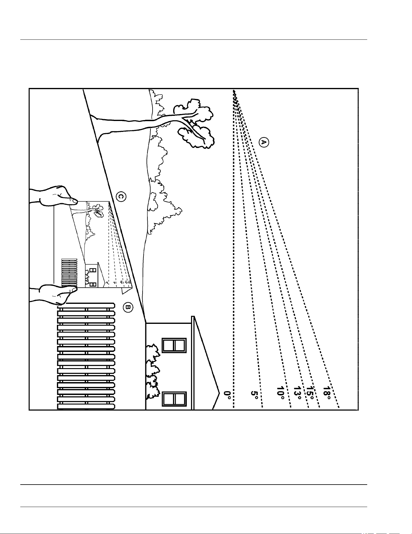
Slope Gauge Template
Hold up or copy this page and follow the directions below to use the Slope Gauge Template.
MXT013189—UN—22APR15
Use this slope gauge to determine if a slope is too steep for safe operation. Do not operate your machine on a slope greater than what is
recommended in your operator’s manual. See Operating on Slopes in the Safety section.
• Fold along the appropriate line (A) to match the recommended slope.
• Align this edge (B) with a vertical surface, a tree, building, fence pole, etc.
• Compare slope (C) with folded edge.
OUMX068,0000513-19-05JUL17
Slope Gauge
SG-1

B
Battery Charge
Level Indicator . . ........ . . . ........ . . ........... . . .. 30-1
Battery, Removing and Installing ... . . ......... . . .... 60-1
Blade Choices...... ........... . . ........ . . ........... . 30-13
Blades, Checking Mower .......... . . ......... . . ...... 55-7
Blades, Service Mower ... . . . ........ . . ........... .... 55-7
C
Charge Maintain Mode....... . . ........ . . ........... . 30-13
Cleanout Areas . . .......... ........... . . ......... . . .... 15-1
D
Deectors
Install, 48 in. Accel Deep deck . . ......... . . ...... 55-4
E
Electrical System ........ ........... . . ......... . . ...... 80-1
Electrical Troubleshooting . . . ........ . . ........... . . .. 70-4
Emissions
Required language
EPA ........... . . ......... . . .......... . . . ........ . . .... 2
F
Fault Table........ . . ........... . . ........ . . ......... . . .. 70-6
Foot Plate, Remove and Install Mower Deck .... 55-1
Full Travel Speed .. . . ......... . . .......... . . . ........ . . 80-1
H
Handle
Install, 48 in. Accel Deep deck . . ......... . . ...... 55-5
I
Icons and Denitions .... . . ......... . . ......... . . ...... 70-1
Identication Numbers, Record ..... . . ........... . . .. 00-1
Instrument Cluster ... . . ......... . . ........... . . ........ 25-1
J
John Deere Quality .. . . ......... . . ........... ...... JDQS-1
L
Labels, Locating Safety ...... . . .......... . . . ........ . . 05-1
Labels, safety with text. . ........... . . ......... . . ...... 05-2
Labels, safety without text ....... ........... . . ........ 06-2
Levers, Using the Motion Control.......... . . ........ 30-7
Lift Machine .... . . .......... . . . ........ . . ........... . . .. 65-1
Lithium Battery Fires ........... . . ........ . . . .......... 10-3
M
Machine Troubleshooting .... . . .......... . . . ........ . . 70-4
Machine, Mounting and Dismounting ..... . . ........ 30-2
Material Collection System, Unclog ....... . . ....... 30-11
Metal Surfaces, Repairing and Cleaning . ........ . . 65-3
Motion Control Levers, Adjust.. . . ........... . . ....... 30-2
Move Machine by Hand....... . . ........ . . . ........ . . 30-10
Mower Deck Identication .... . . ........ . . . ........ . . . 55-1
Mower Deck Troubleshooting .... . . ......... . . ....... 70-5
Mower Deck, Cleaning ............ . . ......... . . ...... 30-11
Mower, Adjust Cutting Height .. . . ......... . . ........ . 30-3
Mower, Adjust Level ........... . . ........ . . . .......... . 30-4
Mower, Engage ... . . ........... . . ........ . . . ........ .. . 30-9
Mower, Install Deck (42-IN) ...... . . ......... . . ....... 55-2
Mower, Remove Deck (42-IN).... . . ........... . . ..... 55-1
Mowing tips... . . . ........ .. ........... . . ......... . . .... 30-13
Mowing Tips ............. . . ......... . . ......... . . ...... 30-13
Mulch blades
Installing, 48 in. Accel Deep deck .. . . . ........ . . . 55-6
Mulch gate stop plate
Install, 48 in. Accel Deep deck . ......... . . ....... 55-4
MulchControl Troubleshooting ... . . ......... . . ....... 70-5
O
Open and closed modes, switching ... . . . .......... . 30-9
Operating Checklist, Daily ........ . . ........... . . ..... 30-1
Operator's Station Controls. . . .......... . . . ........ . . . 25-1
Optimize Battery ........ ........... . . ......... . . ....... 75-1
Order Service Parts Online..... . . ......... . . .......... . . . 3
P
Park Brake, Test .. .. ........... . . ........ . . . .......... . 30-6
Park Brake, Use . . ........... . . ........ . . ......... . . ... 30-6
Parts..... . . ......... . . ......... . . .......... . . . ........ . . ..... 3
Plastic And Painted Surfaces, Avoid Damage To 30-1
Power Button...... . . ........... .......... . . . ........ . . . 30-1
Prevent Fires .......... . . ........... . . ......... . . ....... 10-4
R
Removing and storing
MulchControl, Accel Deep deck .... . . . ........ . . . 55-5
Removing Machine from Storage............. . . ..... 75-1
S
Safely
Use your mower . ......... . . .......... ........... . . . 10-1
Safely parking . . . ........ . . ........... . . ......... . . ..... 10-4
Safety
Electrical . . . ........... . . ......... . . ......... . . ....... 10-3
Label
Location . . . .......... . . . ........ . . ......... . . ..... 06-1
Safety label
Danger .......... . . ......... . . ........ . . ....... 05-2, 05-3
Warning .... . . . ........ . . ......... . . ........... . . ..... 05-2
Safety labels, with text . . . ......... . . ........... . . ..... 05-2
Safety labels, without text ...... . . ......... . . ......... 06-2
Safety Systems, Test........ . . ........ . . ........... . . . 30-5
Seat, Adjusting ...... ........... . . ........ . . . .......... . 30-2
Service Intervals ........ ........... . . ......... . . ....... 35-1
Service Literature ......... . . . .......... . . ......... . . ....... 3
Index
Index-1

Slopes, operating on
Terrain hazards, operating near . . . ........... . . .. 10-2
Special Messages ......... . . . ........ . . ........... . . ...... 3
Specications
Dimensions.... . . ........ . . . .......... . . ......... . . .. 80-1
Mower Decks ....... . . ......... . . ........... . . ...... 80-2
Tires .......... . . ........ . . ........... . . ......... . . .... 80-1
Start the machine.. . . ........... . . ........ . . . .......... 30-9
Stop the machine ........ . . ......... . . ........... . . .... 30-9
Storage, Preparing Machine for. ........... . . ........ 75-1
Switch, Test Mower Engagement (PTO)...... . . .... 30-6
Switch, Test Park Brake . . ......... . . ........... . . .... 30-5
Switch, Test Seat ........ . . ........... ........... . . .... 30-6
Switch, Using the Mower Engagement . . . ........ . . 30-7
T
Template, slope gauge .. . . ......... . . ........... . . ... SG-1
Tire Pressure, Checking . . ......... . . ......... . . ...... 65-1
Transport Machine on Trailer.. . . ........ . . . ......... 30-12
Transporting Material Collection System.... . . ..... 30-13
Troubleshooting chart .......... . . ........... . . ........ 70-3
U
Unclog Mower........ . . ........... ........... . . ....... 30-11
Use Charging port . . . ........... . . ........ . . . ......... 30-10
W
Warranty Registration .......... . . ........ . . . .......... 00-1
Warranty, product ........ . . ........... . . ......... . . .... 85-1
Wheel Assembly, Remove and Install.. . . . ........ .. 65-1
Wheels, Adjust Mower ....... . . ........ . . ........... . . 30-3
Wheels, Remove and Install Front Caster........ . . 65-2
Index
Index-2
