

Z300 Series Residential Zero Turn Mowers
Serial Number 150001-
OPERATOR'S MANUAL
Z315E, Z325E, Z320M, Z330M, Z320R,
Z330R, Residential ZTrak
OMUC45276 ISSUE K5 (ENGLISH)
*OMUC45276*
CALIFORNIA
Proposition 65 Warning
Diesel engine exhaust and some of its constituents
are known to the State of California to cause cancer,
birth defects, and other reproductive harm.
If this product contains a gasoline engine:
WARNING
The engine exhaust from this product contains
chemicals known to the State of California to cause
cancer, birth defects or other reproductive harm.
The State of California requires the above two warnings.
John Deere Power Products
North American Edition
PRINTED IN U.S.A.
*DCY**omuc45276*

Thank You for Purchasing a John Deere
Product
We appreciate having you as a customer and wish you
many years of safe and satised use of your machine.
MX00654,000020B-19-17SEP25
Required Emission-Related Information
Service Provider
A repair shop or person of the owner's choosing may maintain, replace, or repair emission control devices and systems with original or equivalent
replacement parts. However, warranty, recall, and all other services paid for by John Deere must be performed at an authorized John Deere
service center.
DX,EMISSIONS,REQINFO-19-08DEC23
Emissions Performance and Tampering
Operation and Maintenance
The engine, including the emissions control system,
shall be operated, used, and maintained in accordance
with the instructions provided in this manual to maintain
the emissions performance of the engine within the
requirements applicable to the engine's category/
certication.
Tampering
No deliberate tampering with or misuse of the engine
emissions control system shall take place; in particular
with regard to deactivating or not maintaining an
exhaust gas recirculation (EGR) or a DEF dosing
system. Tampering with an engine’s emissions control
system will void the European Union (EU) type approval
and applicable emissions-related warranties.
DX,EMISSIONS,PERFORM-19-12JAN18
Using Your Operator’s Manual
Read this operator’s manual, watch the safety video,
www.deere.com/QR and review the safety signs on your
machine before use. They all contain important safety
information and operating instructions that must be
followed to help keep you and others safe. Be sure
everyone who uses the machine has read the manual,
reviewed the safety signs, and knows how to use the
machine safely and properly.
Your machine was designed and built to be operated in
accordance with all the safe operating instructions.
Since it was designed to cut grass, it can amputate
hands and feet and throw objects. If you do not follow
safety instructions, serious injury or death can occur.
This operator manual is organized in sections to help
you nd information quickly. You can use this manual to
nd answers to many of your operating and servicing
questions. An index at the end of this book helps you
nd needed information quickly. Contact your dealer if
this manual does not answer your questions.
Before using your machine:
● Know how to operate the machine. The Operating
Controls section helps you understand the controls of
your machine and what they do.
● Prepare your machine and the mowing area by
performing required daily checks outlined in the
General Instructions section.
● Follow instructions in the Preventing Injuries section,
especially related to:
- Keeping children safe by following instructions in
the Protect Children section.
- Avoiding injury on slopes and near terrain
hazards by following instructions in the Operating
on Slopes and Near Terrain Hazards section.
- Follow the instructions in the Avoid Thrown
Objects section and keep all guards in place,
including discharge chute.
- Cleaning machine during use and before storing
as outlined in the Prevent Fires section.
● Understand how to service and inspect your
machine.
If you do not understand the instructions or have
questions, contact your dealer.
The machine shown in this manual can dier slightly
from your machine.
RIGHT-HAND and LEFT-HAND sides are determined
by facing in the direction that the machine travels when
going forward. When you see a broken line (------), the
item referenced is hidden from view.
Before delivering this machine, your dealer performed a
predelivery inspection to ensure best performance.
Introduction
This manual is an important part of your machine. Keep
this manual with the machine when you sell it.
mk71445,1654877011782-19-10JUN25
John Deere Is at Your Service
TS201—UN—15APR13
Customer satisfaction is important to John Deere.
Our dealers strive to provide you with prompt, ecient
parts, and service:
• Maintenance and service parts to support your
equipment.
• Trained service technicians and the necessary
diagnostic and repair tools to service your equipment.
• John Deere replacement parts, repair services,
and information for maintenance or repair are
available. For more information, please visit deere.
com or deere.ca.
DX,IFC,JDS-19-30SEP25
Spark Arrestor
The California Public Resources Code, Section 4442.5
provides as follows:
No person shall sell, oer for sale, lease, or rent to any
person any internal combustion engine subject to
Section 4442 or 4443, and not subject to Section 13005
of the Health and Safety Code, unless the person
provides a written notice to the purchaser or bailee, at
the time of sale or at the time of entering into the lease
or rental contract, stating that it is a violation of Section
4442 or 4443 to use or operate the engine on any forest-
covered, brush-covered, or grass-covered land unless
the engine is equipped with a spark arrestor, as dened
in Section 4442, maintained in eective working order or
the engine is constructed, equipped, and maintained for
the prevention of re pursuant to Section 4443. Cal.
Pub. Res. Code 4442.5. Other states or jurisdictions
may have similar laws. A spark arrestor for your
machine may be available from your John Deere dealer
or other servicing provider. An installed spark arrestor
must be maintained in good working order by the
operator.
OUO2005,00006F6-19-17OCT25
Special Messages
Your manual contains special messages to bring
attention to potential safety concerns and machine
damage, as well as helpful operating and servicing
information. Please read all the information carefully to
avoid injury and machine damage.
CAUTION: Avoid injury! This symbol and text
highlight potential hazards or death to the
operator or bystanders that may occur if the
hazards or procedures are ignored.
IMPORTANT: Avoid damage! This text is used to tell
the operator of actions or conditions that might
result in damage to the machine.
NOTE: General information is given throughout the
manual that may help the operator in the operation
or service of the machine.
MX00654,000020D-19-04AUG25
Parts
We recommend John Deere quality parts and
lubricants, available at your John Deere dealer.
When you order parts, your John Deere dealer needs
the serial number or product identication number (PIN)
for your machine or attachment. These are the numbers
that you recorded in the Product Identication section of
this manual.
Order Service Parts Online
Visit https://partscatalog.deere.com/jdrc/ for your
Internet connection to parts ordering and information.
TC00531,00000E9-19-04AUG25
Service Literature
If you would like to purchase a copy of the Parts Catalog
or Technical Manual for this machine, visit The John
Deere Technical Information Store at:
https://techpubs.deere.com/
or call:
● U.S. & Canada: 1-800-522-7448.
● All Other Regions: Your John Deere dealer.
TH84124,0000199-19-04AUG25
Introduction

Page
Product Identication
Record Identication Numbers ......... ..... ..... . .. 00-1
Register Your Product and Warranty Online ..... .. 00-1
Safety Labels with Text
Safety Label Location . . ..... ..... ...... ..... ...... .... 05-1
Understanding the Machine Safety Labels . ...... .. 05-2
WARNING .... ..... . .... . ..... ..... ...... ..... ..... . .... 05-2
DANGER .... . .... . ..... ........... ...... ..... ..... . .... 05-2
DANGER .... . .... . ..... ........... ...... ..... ..... . .... 05-2
WARNING .... ..... . .... . ..... ..... ...... ..... ..... . .... 05-3
CAUTION .... ..... . .... . ..... ..... ...... ..... ..... . .... 05-3
CAUTION .... ..... . .... . ..... ..... ...... ..... ..... . .... 05-3
DANGER .... . .... . ..... ........... ...... ..... ..... . .... 05-3
DANGER .... . .... . ..... ........... ...... ..... ..... . .... 05-4
Hot Surface (Molded into Muer) .. . ..... ..... ...... 05-4
Safety Labels without Text
Safety Label Location . . ..... ..... ...... ..... ...... .... 06-1
Understanding the Machine Safety Labels
without Text ..... . ..... ..... ...... ...... ..... ..... . .. 06-2
Avoid Injury from Loaded Spring ..... ..... ...... .... 06-2
Avoid Injury from Rotating Blades ..... . .... . ..... .. 06-2
Avoid Injury from Getting Caught in Belts ... . .... . . 06-2
Read Operator’s Manual .... ...... ..... . .... . .... . ... 06-2
Keep Children Away from Mower ..... . .... . .... . ... 06-2
Avoid Injury From Tipping .. . .... . ..... ..... ...... .... 06-3
Avoid Injury from Equipment Fires . ........... ..... . 06-3
Avoid Injury from Thrown Objects ..... . .... . .... . ... 06-3
Hot Surface (Molded into Muer) .. . ..... ..... ...... 06-3
Safety
Use Your Mower Safely ..... ...... ..... . .... . .... . ... 10-1
Preventing Injuries .... ........... ..... . .... . .... . ..... 10-2
Operating on Slopes and Near Terrain
Hazards ..... ..... . .... . .... . ..... ...... ..... ..... . .. 10-2
Prevent Fires . . .... . ..... ..... ...... ..... . .... . .... . ... 10-3
Parking Safely ..... ...... ..... ..... . .... . .... . ..... .... 10-4
Additional Safety Information ....... ..... ..... . .... . . 10-4
Machine Cleanout
General Cleaning Guidelines ....... ..... ..... . .... . . 15-1
Cleanout Areas . ..... ...... ..... ..... . .... . .... . ..... .. 15-1
Operating Controls
Operator’s Station Controls ..... ..... . .... . .... . ..... 25-1
Operating
Daily Operating Checklist ..... . ..... ........... ..... . 30-1
Avoid Damage to Plastic and Painted
Surfaces .. .... . .... . ..... ..... ...... ..... ..... . .... . . 30-1
Page
Mounting and Dismounting Machine .. ..... ...... ... 30-1
Adjusting Seat .... . ..... ..... ...... ..... . .... . .... . .... 30-1
Adjusting Motion Control Levers .... . .... . ..... ..... 30-1
Adjusting Cutting Height . ..... ..... . .... . .... . ..... ... 30-2
Adjusting Mower Level ..... ...... ..... . .... . .... . .... 30-2
Adjusting Mower Wheels ..... ...... ..... ..... . .... . .. 30-4
Testing Safety Systems ... ..... ...... ..... ..... . .... . 30-4
Testing Park Brake Switch ..... ...... ..... ..... . .... . 30-5
Testing Park Brake . .... . .... . ..... ...... ..... ..... . ... 30-5
Testing Mower Engagement (PTO) Switch .. ..... . 30-5
Testing Seat Switch ... . .... . .... . . .... ..... ...... ..... 30-5
Using Park Brake .. ...... ..... ..... . .... . .... . ..... ... 30-6
Using Key Switch .. ...... ..... ..... . .... . .... . ..... ... 30-6
Using Mower Engagement Switch ........... ..... . . 30-7
Using the Hour Meter ........... ..... . .... . .... . ..... . 30-7
Using the Motion Control Levers .... ..... ...... ..... 30-7
Using Dual Levers (If Equipped) .... . .... . ..... ..... 30-9
Starting the Machine . ........... .... . . .... . .... . ..... . 30-9
Engaging Mower . . ..... ..... ...... ...... ..... ..... . .. 30-10
Using MulchControl (If Equipped) . ........... ..... . 30-10
Unplugging Mower ..... ..... ...... ..... . .... . .... . ... 30-10
Stopping the Machine . . .... . ..... ...... ..... ..... . .. 30-10
Move Machine by Hand .... . ..... ...... ..... ..... . .. 30-11
Unplugging Mower, Bagger, or Material
Collection System ... . .... . ..... ...... ..... ..... . .. 30-11
Using Wash Port to Clean Mower Deck . ...... .... 30-12
Transport Machine on Trailer ...... ........... ..... . 30-12
Transporting Material Collection System (If
Equipped) .. ..... . .... . .... . ..... ...... ..... ..... . .. 30-13
Towing Loads . ..... . .... . .... . ..... ...... ..... ..... . .. 30-13
Mowing Tips . .... . .... . ..... ..... ...... ..... ..... . .... 30-13
Blade Choices .... . ..... ..... ...... ..... . .... . .... . ... 30-14
Service Intervals
Servicing Your Machine .... ..... . .... . .... . ..... ..... 35-1
Service Intervals ... . .... . .... . ..... ...... ..... ..... . ... 35-1
Service Lubrication
Grease .... ..... ..... . .... . .... . ..... ...... ..... ..... . ... 40-1
Lubricating Mower Deck Spindles . .... . .... . ..... ... 40-1
Service Engine
Emissions Service Information ... . .... . .... . ..... ... 45-1
Avoid Fumes ........ ..... . .... . .... . ..... ..... ...... ... 45-1
Gasoline Engine Oil . ..... ..... ...... ..... ..... . .... . .. 45-1
Checking Engine Oil Level . . ..... ...... ..... ..... . ... 45-2
Changing Conventional Engine Oil and Filter .. ... 45-2
Cleaning Air Intake Screen and Engine Fins ... . .. 45-3
Cleaning Engine Shroud ....... .... . . .... ..... ...... . 45-3
Checking and Cleaning Air Cleaner Element ... ... 45-4
Checking and Cleaning Air Cleaner Element ... ... 45-5
Checking Spark Plug .... . .... . ..... ........... ..... . . 45-6
Continued on next page
Original Instructions. All information, illustrations and specications in this
manual are based on the latest information available at the time of publication.
The right is reserved to make changes at any time without notice.
COPYRIGHT © 2025
DEERE & COMPANY
Moline, Illinois
All rights reserved.
Previous Editions
Copyright © 2024
Contents
i

Page
Replacing Fuel Filter .. .... . .... ...... ........... ..... . 45-7
Cleaning Engine Screen Guard . ..... ..... ...... .... 45-7
Spark Arrestor Maintenance (If Equipped) ... ...... 45-8
Cleaning Spark Arrestor ... ..... . .... . ..... ..... ...... 45-8
Service Transmission
Checking Transmission .. .... . ..... ...... ..... ..... . .. 50-1
Checking and Adjusting Neutral Creep ....... ..... . 50-1
Adjusting Tracking ...... ..... ..... . .... . .... . ..... .... 50-2
Cleaning Transaxle Cooling Fans .... . .... . ..... .... 50-2
Checking and Replacing Transaxle/
Transmission Drive Belt ...... ..... . .... . .... . ..... 50-3
Service Mower
Mower Deck Identication ..... ...... ..... ..... . .... . . 55-1
Removing and Installing Mower Deck Foot
Plate .... ..... ...... ..... . .... . .... . ..... ..... ...... .. 55-1
Removing Mower Deck (42A) .. .... . ..... ..... ...... 55-1
Removing Mower Deck (48A and 54A) .... . ..... .. 55-2
Installing Mower Deck (42A) .... ...... ..... ..... . .... 55-4
Installing Mower Deck (48A and 54A) .... ..... . .... 55-5
Replacing Mower Drive Belt (42A Mower) . ...... .. 55-7
Replacing Mower Drive Belt (48A and 54A
Mower Decks) .... ..... . .... . .... . ..... ..... ...... .. 55-8
Installing MulchControl Discharge Plate (If
Equipped) .. . .... . ..... ..... ...... ..... . .... . .... . ... 55-8
Installing MulchControl Deector (If
Equipped) .. . .... . ..... ..... ...... ..... . .... . .... . ... 55-9
Installing MulchControl Handle (If Equipped) .... . 55-10
Removing and Storing MulchControl Deck (If
Equipped) .. . .... . ..... ..... ...... ..... . .... . .... . .. 55-10
Installing Mulch Blades ..... ..... ...... ..... ..... . ... 55-11
Checking for Bent Mower Blades ... . .... . .... . .... 55-11
Servicing Mower Blades ..... ..... . .... . .... . ..... ... 55-12
Service Electrical
Electrical . .... . .... . ..... ........... ..... . .... . .... . ..... 60-1
Service the Battery Safely ... . .... . ..... ..... ...... .. 60-1
Removing and Installing the Battery . . .... . ..... .... 60-1
Cleaning Battery and Terminals .. . ..... ..... ...... .. 60-1
Use Booster Battery .. ..... ..... . .... . ..... ..... ...... 60-2
Replacing Fuse .. ..... . .... . .... . ..... ........... ..... . 60-2
Service Miscellaneous
Gasoline Fuel for 4-Cycle Engines ..... ..... ...... .. 65-1
Fill Fuel Tank .. ...... ..... . .... . .... . ..... ..... ...... .. 65-1
Lifting Machine .. . ..... ........... ..... . .... . .... . ..... 65-1
Checking Tire Pressure ..... ..... . .... . .... . ..... .... 65-2
Removing and Installing Wheel Assembly ..... .... 65-2
Removing and Installing Front Caster
Wheels . . .... . ..... ...... ..... ..... . .... . .... . ..... .. 65-3
Cleaning and Repairing Metal Surfaces ..... . .... . . 65-4
Troubleshooting
Using Troubleshoot Chart . ..... . .... . ..... ..... ...... 70-1
Engine .. . .... . .... . ..... ........... ..... . .... . .... . ..... 70-1
Electrical . .... . .... . ..... ........... ..... . .... . .... . ..... 70-1
Machine . ........... ..... . .... . .... . ..... ..... ...... .... 70-2
Mower .. ..... ..... ...... ..... ..... . .... . ..... ..... ...... 70-2
MulchControl (If Equipped) ...... ..... . .... . .... . ..... 70-2
Storage
Storing Safety .. . .... . ..... ..... ...... .......... . .... . . 75-1
Page
Preparing Machine for Storage .. ...... ..... ..... . ... 75-1
Preparing Fuel and Engine For Storage ... . .... . .. 75-1
Removing Machine From Storage .. .... . .... . ..... . 75-2
Specications
Engine .. ..... . .... . .... . ..... ..... ...... ..... ..... . .... . 80-1
Drivetrain .... . .... . .... . ..... ..... ...... ..... ...... ..... 80-1
Travel Speeds at Full Engine RPM ... . .... ...... ... 80-1
Electrical System .. . .... . .... . ..... ...... ..... ..... . ... 80-2
Fuel System ... ..... ...... ..... ..... . .... . .... . ..... ... 80-2
Tires ...... ..... ..... . .... . .... . ..... ...... ..... ..... . ... 80-2
Capacities .. ..... ...... ..... ..... . .... . ..... ..... ...... . 80-2
Dimensions .... . .... . ..... ..... ...... ..... ..... . .... . .. 80-2
Recommended Lubricants . .... . ..... ..... ...... ..... 80-2
Mower Decks .. ..... ...... ..... ..... . .... . .... . ..... ... 80-3
Warranty
Product Warranty ...... . .... . .... . ..... ..... ...... ..... 85-1
U.S. EPA Emission Control System Warranty
Statement (O-Road Engine Equipment) .. . .... 85-1
Tire Warranty ... ..... . .... . .... . ..... ........... ..... . . 85-3
Limited Battery Warranty For Factory
Installed Batteries ... ..... ...... ..... . .... . .... . .... 85-3
John Deere Quality Statement
John Deere Quality ... . .... . .... . ..... ..... ...... . JDQS-1
Service Record
Record Service Dates . ..... ...... ..... . .... . .... . ... SR-1
Slope Gauge
Slope Gauge Template .. ..... ...... ..... ..... . .... . . SG-1
Contents
ii
Record Identication Numbers
Zero-Turn Mowers
When you contact an Authorized Service Center for
information on servicing, always provide the product
model and identication numbers.
Locate the model and serial number for the machine,
engine, and transmission/transaxle of your machine and
record the information in the spaces provided as follows.
DATE OF PURCHASE:
_________________________________________
DEALER NAME:
_________________________________________
DEALER PHONE:
_________________________________________
APY536232—UN—25APR22
Product Identication Number (A):
__ __ __ __ __ __ __ __ __ __ __ __ __ __ __ __ __
Engine Serial Number:
On engine blower housing.
__ __ __ __ __ __ __ __ __ __ __ __ __ __ __ __ __
Transaxle Serial Numbers (B):
S/N tag on forward side of each transaxle housing.
LEFT SIDE:
__ __ __ __ __ __ __ __ __ __ __ __ __ __ __ __ __
RIGHT SIDE:
__ __ __ __ __ __ __ __ __ __ __ __ __ __ __ __ __
GH8XT3T,00008E4-19-01MAY22
Register Your Product and Warranty Online
To register your product through the Internet, simply go
to www.JohnDeereWarrantyRegistration.com.
Completing the information, either online or with the
product warranty card, will ensure that your product will
receive all post sales, service, and important product
information.
MP47322,00F45FF-19-17MAY22
Product Identication
00-1
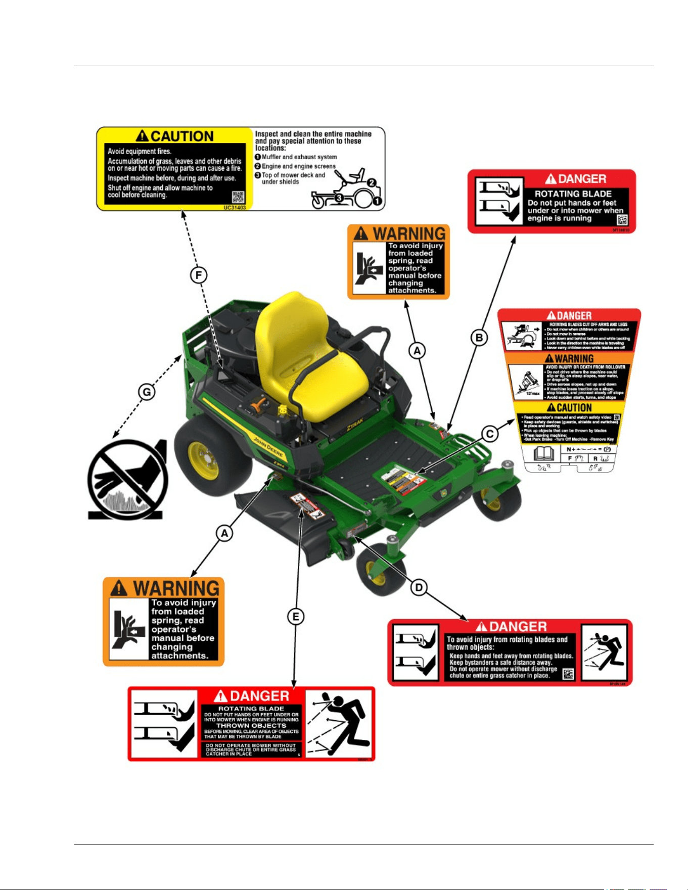
Safety Label Location
GX663353—UN—08MAY25
.
A—WARNING M146577 B—DANGER M118610
Safety Labels with Text
05-1
C—DANGER, WARNING, CAUTION UC45451
D—DANGER M139128
E—DANGER M89504
F—CAUTION UC31403
G—Hot Surface (Molded into Muer)
SDHTXN6,1746551878588-19-12MAY25
Understanding the Machine Safety Labels
MXAL42363—UN—22MAY13
The machine safety labels shown in this section are
placed in important areas on your machine to draw
attention to potential safety hazards. DANGER or
WARNING safety labels are located near specic
hazards.
The operator’s manual also explains any potential
safety hazards whenever necessary in special safety
messages that are identied with the word, CAUTION,
and the safety-alert symbol.
On your machine safety labels, the words DANGER,
WARNING, and CAUTION are used with this safety-
alert symbol. DANGER identies the most serious
hazards:
● DANGER; The signal word DANGER indicates a
hazardous situation which, if not avoided, will result
in death or serious injury.
● WARNING; The signal word WARNING indicates a
hazardous situation which, if not avoided, could
result in death or serious injury.
● CAUTION; The signal word CAUTION indicates a
hazardous situation which, if not avoided, could
result in minor or moderate injury. CAUTION may
also be used to alert against unsafe practices
associated with events which could lead to personal
injury.
Replace missing or damaged safety labels. Use this
operator’s manual for correct safety label placement.
There can be more safety information contained on
parts and components sourced from suppliers that is not
reproduced in this operator’s manual.
French or Spanish Safety Labels and Operator’s
Manual
Operator’s manuals and safety labels with content in
French or Spanish are available for this machine
through authorized John Deere dealers. See your John
Deere dealer.
NOTE: Both text and no-text labels are shown. Your
machine is only equipped with one of these types of
labels.
MP47322,00F4601-19-21FEB23
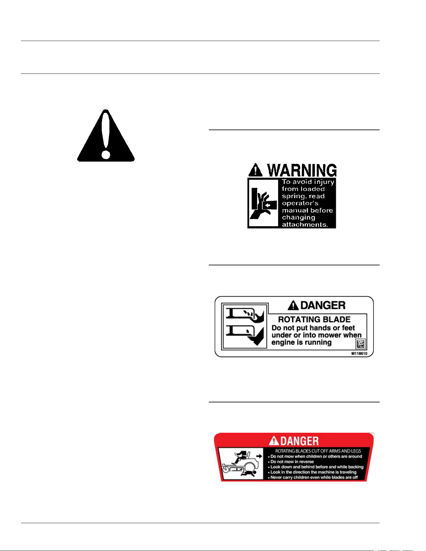
WARNING
MXAL42769—UN—09APR13
To avoid injury from loaded spring, read operator’s
manual before changing attachments.
TH84124,000017E-19-28OCT16
DANGER
MG512220—UN—08JUN21
ROTATING BLADE
Do not put hands or feet under or into mower when
engine is running.
MG39705,00005BA-19-09JUN21
DANGER
APY571651—UN—23MAR23
ROTATING BLADES CUT OFF ARMS AND LEGS
● Do not mow when children or bystanders are around.
Safety Labels with Text
05-2
● Do not mow in reverse unless necessary.
● Look down and behind before backing up.
● Look in the direction of travel.
● Never carry children on the machine, even with the
blades o.
SDHTXN6,1746607525735-19-07MAY25
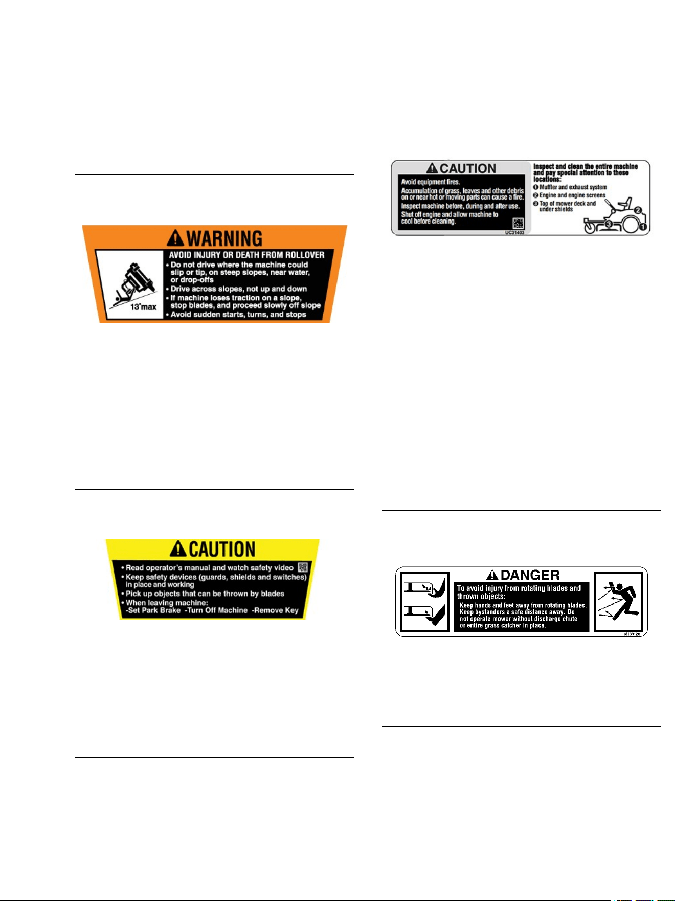
WARNING
GX663354—UN—08MAY25
AVOID INJURY OR DEATH FROM ROLLOVER
● Do not drive where the machine could slip or tip: on
steep slopes, near water, or near drop-os.
● Never mow or operate the machine on slope angles
greater than 13°.
● Drive across slopes, instead of up and down.
● If the machine loses traction on a slope, stop the
blades and proceed slowly o the slope.
● Avoid sudden starts, turns, or stops.
SDHTXN6,1746607535877-19-12JUN25
CAUTION
APY571653—UN—21MAR23
● Read the operator's manual and watch the safety
video.
● Keep safety devices (guards, shields, and switches)
in place and working.
● Pick up objects that can be thrown by the blades.
● When leaving machine, do the following:
- Set Park Brake - Turn o Machine -Remove Key.
SDHTXN6,1746607582773-19-07MAY25
CAUTION
APY592562—UN—01SEP23
● Avoid Equipment res.
● Accumulation of grass, leaves and other debris on or
near hot or moving parts can cause a re.
● Inspect machine before, during and after use.
● Shut o engine and allow machine to cool before
cleaning.
Inspect and clean the entire machine and pay
special attention to these location:
1.Muer and exhaust system.
2.Engine and engine screens.
3.Top of mower deck and under shields.
gh8xt3t,1654880564263-19-01SEP23
DANGER
MXAL42773—UN—09APR13
To avoid injury from rotating blades and thrown objects:
Keep hands and feet away from rotating blades. Keep
bystanders a safe distance away. Do not operate mower
without discharge chute or entire grass catcher in place.
TH84124,000017F-19-01SEP23
Safety Labels with Text
05-3

DANGER
MXT008505—UN—01NOV16
ROTATING BLADE
DO NOT PUT HANDS OR FEET UNDER OR INTO
MOWER WHEN ENGINE IS RUNNING.
THROWN OBJECTS
BEFORE MOWING, CLEAR AREA OF OBJECTS
THAT MAY BE THROWN BY BLADE.
DO NOT OPERATE MOWER WITHOUT DISCHARGE
CHUTE OR ENTIRE GRASS CATCHER IN PLACE.
TH84124,0000162-19-01NOV16
Hot Surface (Molded into Muer)
MX632707—UN—07JUN24
● Do not touch engine muer.
gh8xt3t,1717769571176-19-26JUN24
Safety Labels with Text
05-4
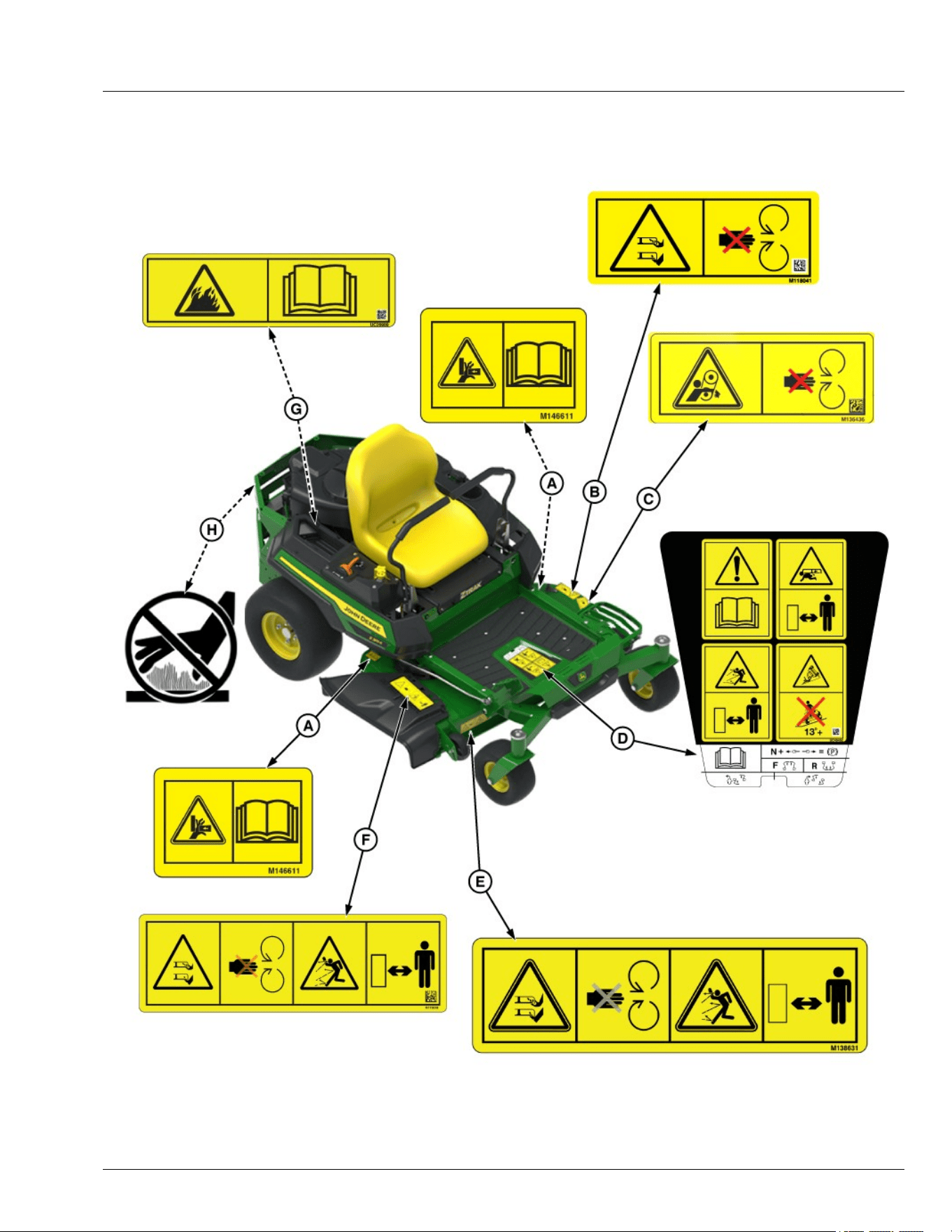
Safety Label Location
GX663355—UN—08MAY25
.
A—WARNING - M146611 B—DANGER - M118041
Safety Labels without Text
06-1
C—DANGER - M136436
D—DANGER, WARNING, CAUTION - UC45452
E—DANGER - M138631
F—DANGER - M173018
G—CAUTION - UC26989
H—Hot Surface (Molded into Muer)
SDHTXN6,1746552064897-19-11MAY25
Understanding the Machine Safety Labels
without Text
TCT005498—UN—11SEP12
The machine safety labels shown in this section are
placed in important areas on your machine to draw
attention to potential safety hazards.
On your machine safety labels, the words DANGER,
WARNING, and CAUTION are used with this safety-
alert symbol. DANGER identies the most serious
hazards.
MX00654,0000389-19-09JAN23
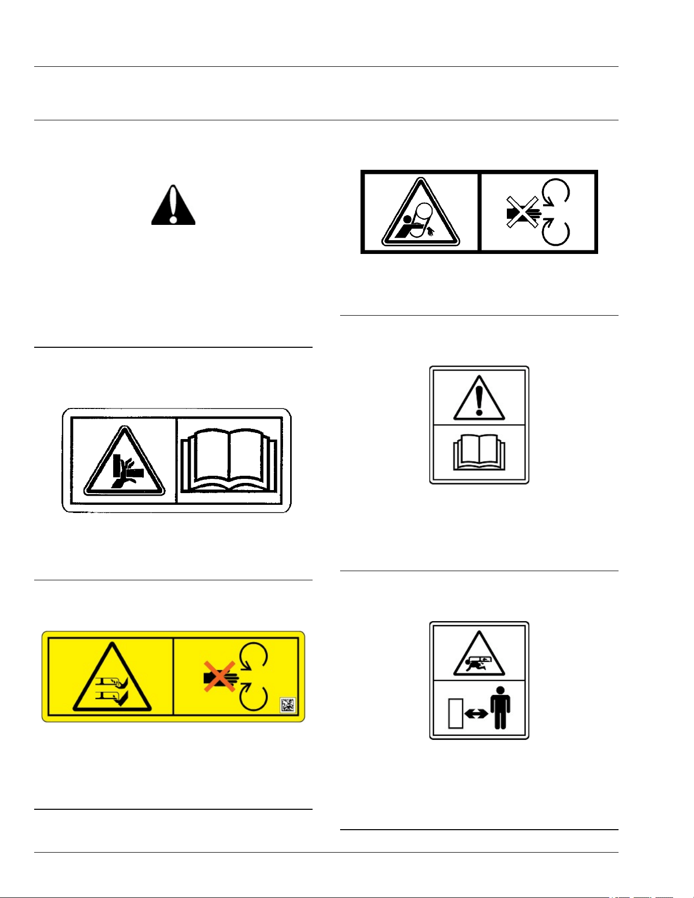
Avoid Injury from Loaded Spring
MXAL42777—UN—09APR13
● Keep ngers and hands away from pinch point.
● Read operator’s manual.
MX00654,000038C-19-24APR19
Avoid Injury from Rotating Blades
TC1362285—UN—28MAR24
● Do not put hands or feet under or into mower when
engine is running.
● Do not operate mower without discharge chute/
deector or entire grass catcher in place.
MX00654,0000392-19-08APR24
Avoid Injury from Getting Caught in Belts
MXT018017—UN—03MAY16
● Stay clear of moving belts.
● Do not operate machine without shields in place.
MX00654,0000391-19-24APR19
Read Operator’s Manual
MXT013479—UN—05MAR15
● This operator’s manual contains important
information necessary for safe machine operation.
● Carefully read operator’s manual before operating
machine. Observe all safety rules to avoid accidents.
TH84124,0000173-19-12JUN15
Keep Children Away from Mower
MXT013480—UN—05MAR15
● Mower can cause dismemberment or death.
● Stay a safe distance from the machine.
● Make sure that children stay clear of mower at all
times when the engine is running.
TH84124,0000174-19-12JUN15
Safety Labels without Text
06-2
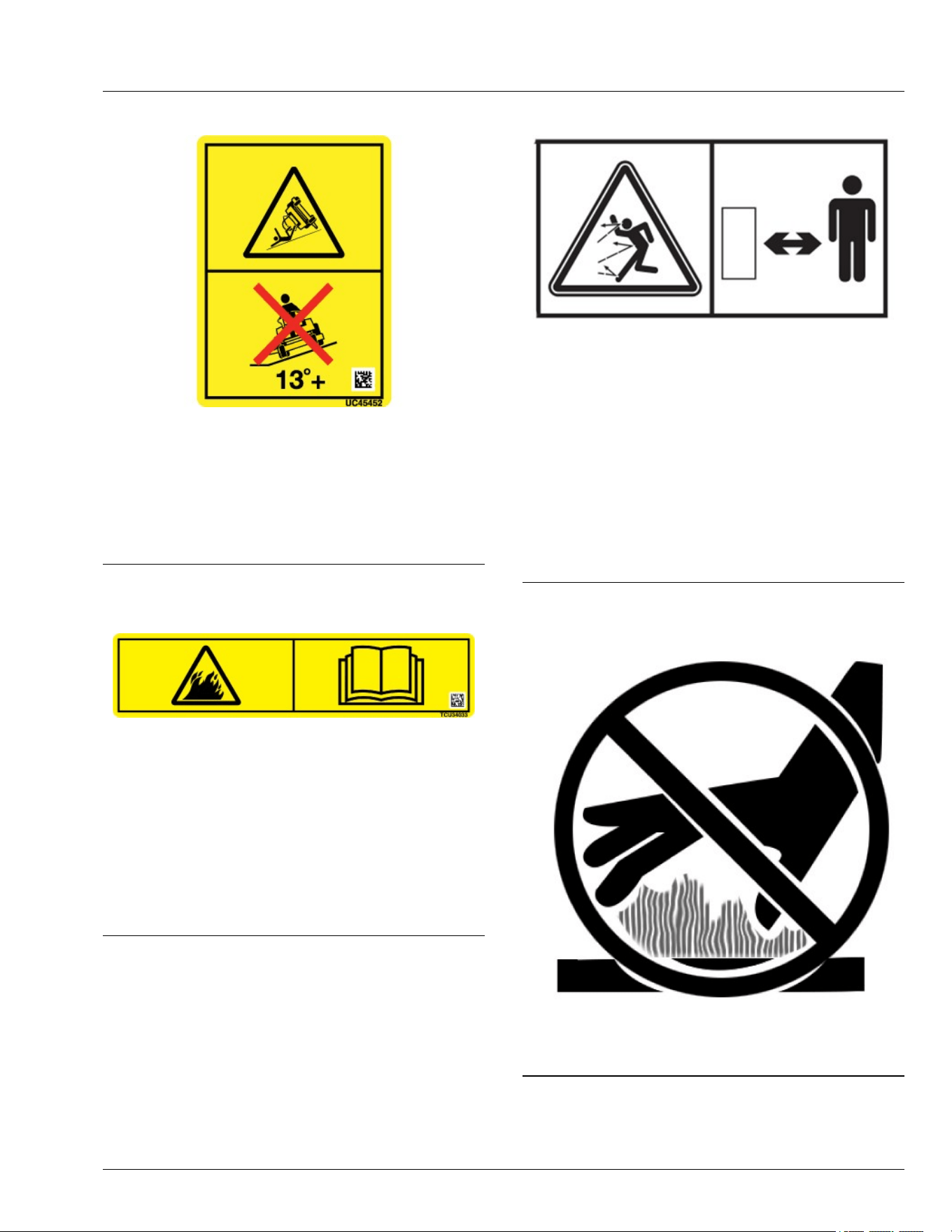
Avoid Injury From Tipping
GX663356—UN—08MAY25
● Do not drive where the machine could slip, tip, or
rollover.
● Never mow or operate the machine on slope angles
greater than 13°.
● Refer to the "Operating on Slopes" section for more
information.
SDHTXN6,1746607452600-19-10JUN25
Avoid Injury from Equipment Fires
TC1362284—UN—28MAR24
● Avoid equipment res.
● Accumulation of grass, leaves, and debris on or near
hot or moving parts can cause a re.
● Inspect and clean the entire machine before, during
and after use.
● Shut o engine and allow machine to cool before
cleaning.
● Carefully read operator’s manual Machine Cleanout
section for details.
MX00654,0000390-19-08APR24
Avoid Injury from Thrown Objects
APY538841—UN—07JUN22
Use extreme care to avoid injury from thrown objects.
Do not, under any circumstances, operate the mower-
conditioner when other people are in the vicinity. Stones
and other objects can be thrown very far by the rotating
cutting blades.
The cutterbar curtains are very important to reduce the
potential for thrown objects. Always keep these curtains
down when operating the mower-conditioner. Replace
the curtains if worn or damaged.
For additional operator protection from thrown objects,
only use this mower-conditioner with a tractor equipped
with a complete operator enclosure.
gh8xt3t,1654611841236-19-07JUN22
Hot Surface (Molded into Muer)
MX632707—UN—07JUN24
● Do not touch engine muer.
gh8xt3t,1717769571176-19-26JUN24
Safety Labels without Text
06-3

Use Your Mower Safely
General Instructions
● Read this operator’s manual, watch the safety video,
and review the safety signs on your machine before
use. They all contain important safety information
and operating instructions that must be followed to
help keep you and others safe. Be sure everyone
who uses the machine has read the manual,
reviewed the safety signs, and knows how to use the
machine safely and properly.
● Never mow when there is a risk of lightning.
● Age, physical ability, and mental capacity can be
factors in equipment-related injuries. Operators must
be mentally and physically capable of operating the
machine properly and safely. Never allow a child to
operate the machine.
● Do not operate the machine while under the
inuence of alcohol or drugs or when distracted or
fatigued. Proper operation requires your full
attention.
● Always wear eye protection, hearing protection,
close-tting clothing, and substantial footwear while
operating the machine. Never operate while wearing
sandals or when barefoot.
● Do not wear radio or music headphones. Both safe
operation and service require your full attention.
● Never tamper with safety devices.
● Operate the machine only in daylight or good articial
light.
● Only operate the engine in well-ventilated areas.
Exhaust gasses contain carbon monoxide, a deadly
poison.
● Never leave a running machine unattended.
● Look both ways when approaching roadways and
use caution when turning around on public
roadways. You can be struck by a vehicle and suer
serious injury or death.
Before Using Your Machine
● Know how to operate the machine. The Operating
Controls section helps you understand the controls of
your machine and what they do.
● Prepare your machine and the mowing area by
performing required daily checks outlined in the
General Instructions section.
● Follow instructions in the Preventing Injuries section,
especially related to:
- Keeping children safe by following instructions in
the Protect Children section.
- Avoiding injury on slopes and near terrain
hazards by following instructions in the Operating
on Slopes and Near Terrain Hazards section.
- Follow the instructions in the Avoid Thrown
Objects section, and keep all guards in place,
including discharge chute.
- Cleaning machine during use and before storing
as outlined in the Prevent Fires section.
● Understand how to service and inspect your
machine.
Inspection and Daily Checklist
● Inspect machine before you operate. Be sure that
hardware is tight, and all guards and shields are in
good condition and fastened in place. Make all
necessary adjustments before you operate. Repair or
replace damaged, badly worn, or missing parts.
● Visually inspect that mower blades, blade bolts, and
the mower assembly are not worn or damaged. To
prevent machine damage, replace worn or damaged
blades and bolts in sets.
● Make sure that the fuel cap and air cleaner are in
place before starting engine.
Fuel
● Use care when handling fuel. Fuel is ammable and
fuel vapors can be explosive. Do not smoke when
handling fuel. Only use an approved fuel container.
Clean up spilled fuel immediately.
● Check fuel lines, tank, cap, and ttings frequently for
cracks or leaks. Replace if necessary.
Check the Mowing Area
● Keep bystanders and pets out of the mowing area.
● Clear the area of objects such as rocks, wire, or toys,
which can be thrown by the blades. Remove low-
hanging branches or other obstacles, which can
interfere with your travel path.
● Study the mowing area. Set up a safe mowing path.
Do not mow where traction or stability is doubtful.
● Slopes and terrain hazards are major factors related
to loss-of-control and tipover accidents. Operation on
slopes and near terrain hazards requires extra
caution. Follow instructions in the Operating on
Slopes and Near Terrain Hazards section.
Weights and Attachments
● Some attachments require ballast weights. Follow
recommendations for wheel weights or
counterweights.
● Use only accessories and attachments approved by
John Deere.
● If you do not understand the instructions or have
questions, contact your dealer or other service
provider.
SDHTXN6,1745840906380-19-29JUL25
Safety
10-1

Preventing Injuries
Protect Children
MXT005340—UN—06JUN13
● Children can be killed or seriously injured by riding
mowers when operators do not follow safe operating
practices.
● Do not mow in reverse. Operating with the mower
engaged while backing up is discouraged.
● Never give children a ride on a mower or in a cart
behind the mower, even when the blades are o.
They can fall o and be run over or cut by the mower
blades. Children can interfere with mower operation.
Children who have been given rides in the past can
suddenly appear in the mowing area for another ride.
If you are not aware, they can be run over or backed
over by the mower.
● Children are often attracted to lawn mowers and
mowing activities, especially if they have been given
rides before. They do not know if the blades are
rotating or understand that they can be killed or
seriously injured even if the blades are not rotating.
● Keep children indoors and out of the mowing area
when the mower is being operated. Keep children
under the watchful eye of a responsible adult, other
than the operator. If there is not a responsible adult to
ensure that children stay indoors, DO NOT mow.
● Be alert to the presence of children or others. Turn o
the mower blades and stop the machine if someone
enters the mowing area.
● Look in the direction the machine is traveling. Before
and while backing, turn o the mower blades and
look down and behind the machine carefully,
especially for children.
● Use extreme care when approaching objects that
block your view, such as blind corners, shrubs, or
trees, especially while backing. They can hide a
child.
Avoid Thrown Objects
● Clear the mowing area of all bystanders when using
this machine. Thrown objects could cause serious
injury or death.
● Clear the area of objects such as rocks, wire, or toys,
which can be thrown by the blades.
● Never direct discharged material toward anyone.
● Avoid discharging material against a wall or
obstruction such as a fence or retaining wall. Material
can ricochet towards the operator.
● Avoid discharging material towards a street or
roadway.
● Stop the blades when crossing gravel surfaces.
OUO2005,000078C-19-15FEB20
Operating on Slopes and Near Terrain
Hazards
● Slopes are a major factor related to loss of control
and tip-over accidents, which can result in serious
injury or death. Use caution and common sense
when operating on slopes.
● If you feel uneasy on a slope, do not mow or operate
the machine on it.
● Mow across slopes, not up and down.
● Watch for holes, ruts, bumps, rocks, or other hidden
objects. Tall grass can hide obstacles.
● Drive slowly so you do not have to stop while on a
slope.
● Do not mow on wet grass. Tires can slip on wet grass
even if the brakes are working normally.
● Keep all movement on slopes slow and gradual. Do
not make sudden changes in speed or direction,
which can cause the ride-on mower to roll over.
● If the tires lose traction, disengage the PTO and
proceed slowly and carefully o the slope.
● Do not shift to neutral and coast downhill.
Identify Safe Slopes
● Before using your machine, measure the slopes of all
mowing areas to determine which slopes are safe for
mowing with a ride-on mower. Use good judgment
and common sense when performing this survey.
Measuring Slopes
● Suggested method 1: Lay a straight piece of sturdy
lumber 1.2 m (4 ft) long on the slope and measure
the angle with an angle gauge or protractor level.
● Suggested method 2: Refer to the slope gauge
provided at the end of the manual.
Slope Limits
● Exceeding the recommended maximum slope angle
increases the risk of rollover accidents that can result
in serious injury or death.
Safety
10-2
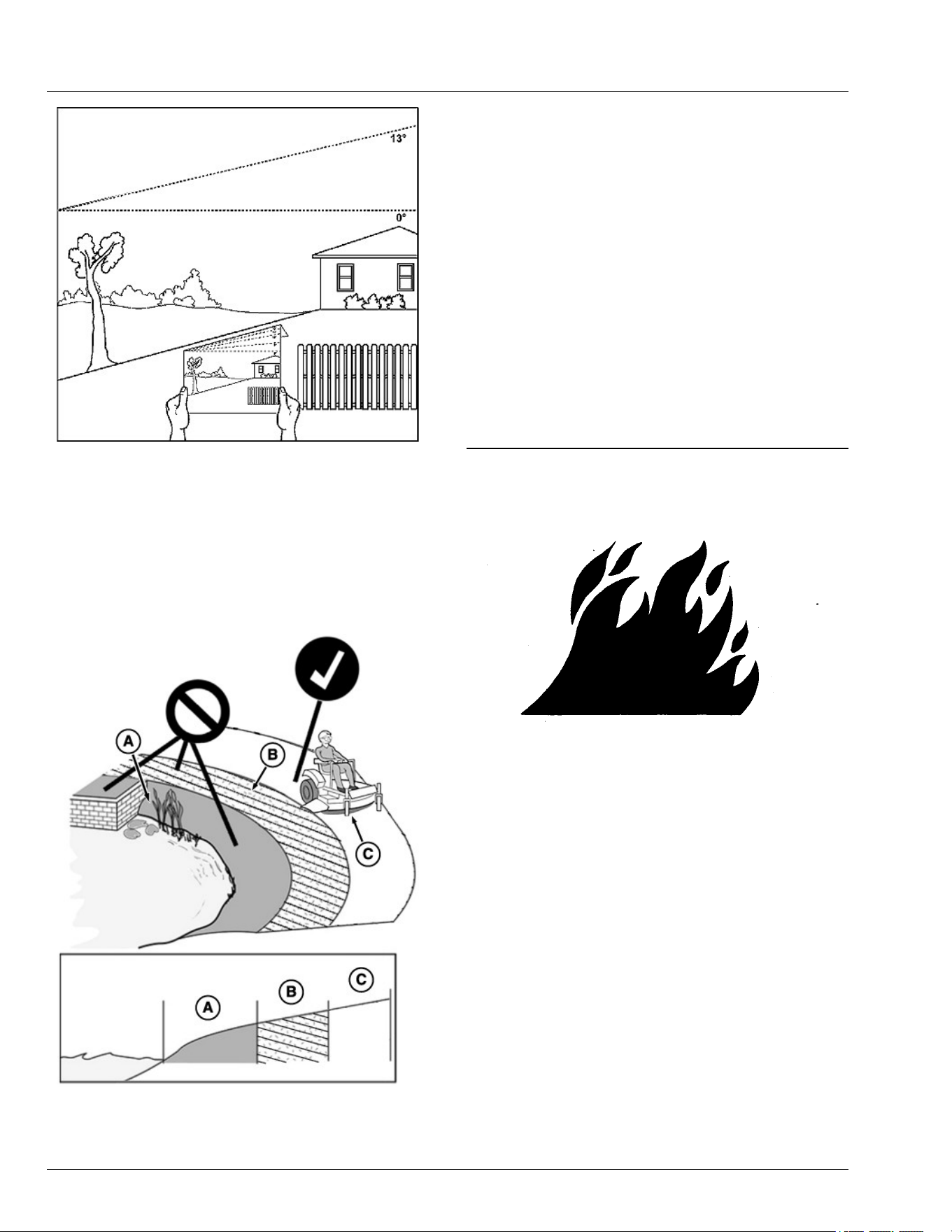
GX100108—UN—14FEB20
● Never mow or operate this ride-on mower on slope
angles greater than 13°. (A 13° slope is a slope that
rises 1.4 m [4.6 ft] over a horizontal distance of 6.1 m
[20 ft].)
● Material collection systems, weather enclosures, or
other attachments increase the risk of a rollover.
● As slope increases the risk of rollover increases.
Operating Near Terrain Hazards
GX100105—UN—01FEB20
● Terrain hazards such as ditches and drop-os are a
factor related to loss of control and tip-over
accidents, which can result in serious injury or death.
Use caution and common sense when operating
near terrain hazards.
● Do not mow or operate the machine in areas
adjacent to hazards that can cause the machine to
roll over. If a wheel goes over an edge or if the edge
breaks away, the machine can suddenly lose
traction, slide, and/or roll over.
● Hazards (A) include but are not limited to ditches,
drop-os, embankments, or areas near bodies of
water.
● Maintain a buer area (B) at least as wide as the
machine between hazards (A) and the mowing area
(C). Do not mow or operate the machine in the
hazard area or buer area.
● Only mow or operate in the mowing area (C). Do not
exceed the recommended slope operating angle.
Refer to the Slope Limits section.
SDHTXN6,1746613701194-19-07MAY25
Prevent Fires
TS227—UN—15APR13
● Do not mow tall, dry grass or through piles of leaves.
Combustible materials can contact hot components
and increase the risk of re.
● Debris can build up anywhere on the machine,
especially on horizontal surfaces. While using your
machine, periodically check for and remove debris,
especially in dry or heavy debris conditions, such as
when collecting leaves.
● After operating, completely remove any combustible
materials from equipment before storing. Use
compressed air, a leaf blower, or water to keep the
machine clean.
● Allow machine to cool in an open area before storing.
Do not park machine near ammable materials, such
as straw, mulch, cloth, or chemicals. Do not park
near an open ame or other sources of ignition, such
as a water heater or furnace.
● Excess lubrication or fuel/oil leaks or spills on the
machine can also provide collection sites for debris.
Promptly cleaning up spills and repairing leaks
reduces the potential for debris collection.
● Refer to the Machine Cleanout section for more
Safety
10-3

information on checking for debris buildup and
locations to inspect.
● Always park the machine safely before cleaning or
servicing a machine. See the Parking Safely section.
OUO2005,0000787-19-15FEB20
Parking Safely
Always apply the park brake and remove the key or key
pin before leaving the machine unattended. Children or
others may attempt to move or operate an unattended
machine.
● Bring the machine to stop on a level surface.
● Disengage mower blades or other attachments.
● Lower attachments to the ground.
● Apply the park brake.
● Shut the machine OFF.
● Remove the key or key pin.
● Wait for all moving parts to stop before you leave the
seat.
● Disconnect battery before maintenance.
OUO2005,0000788-19-12APR23
Additional Safety Information
Towing Loads Safely
● Stopping distance increases with speed and weight
of towed load. Travel slowly and allow extra time and
distance to stop.
● Total towed weight must not exceed Towing Capacity
stated in Specications of this manual.
● Excessive towed load can cause loss of traction and
loss of control on slopes. Reduce towed weight when
operating on slopes.
● Never allow children or others in or on towed
equipment.
● Use only approved hitches. Tow only with a machine
that has a hitch designed for towing. Do not attach
towed equipment except at the approved hitch point.
● Towed equipment increases the risk of rollover on
slopes. Refer to the Operating on Slopes and Near
Terrain Hazards section for more information.
● Do not turn sharply. Use additional caution when
turning or operating on adverse surface conditions.
Use care when reversing.
Safe Transportation
Follow instructions in the Transporting Machine on
Trailer section.
● Use a full-width loading ramp at least 30 cm (12 in)
wider than the machine, never two separate ramps.
Service and Maintenance
● Proper service and maintenance of the machine is
essential.
● Keep all parts in good condition, keep all nuts and
bolts tight, and repair any damage immediately. Stop
and inspect the machine immediately if you strike an
object.
● Ensure that all safety devices, discharge chute, and
grass catcher components are in good condition and
replace when necessary.
● Understand service procedures thoroughly before
working on the machine. If you do not understand the
service procedures or are uncomfortable working in
your machine, contact your John Deere dealer or
other service provider.
● Disconnect the battery or all spark plug wires before
servicing the machine. Disconnect negative terminal
rst and positive last. Install positive terminal rst and
negative last.
● Some components could have stored energy in
springs or hydraulic components. Servicing
procedures described in the Service section describe
how to perform service and maintenance tasks
safely.
● Support any machine elements that must be raised
for service work. Use jack stands or service locks to
support components when needed.
Disposing of Waste Products and Chemicals
● Waste products, such as used oil, fuel, coolant, brake
uid, and batteries can harm the environment and
people.
● Do not use beverage containers for waste uids –
someone can mistakenly drink from them.
● A Safety Data Sheet (SDS) provides specic details
on chemical products: Physical and health hazards,
safety procedures, and emergency response
techniques. The seller of the chemical products used
with your machine is responsible for providing the
SDS for that product.
● To learn how to recycle or properly dispose of waste
products generated from service, see your local
recycling center, John Deere dealer, or other service
provider. If you wish to discard the machine, contact
your local recycling center, John Deere dealer, or
other service provider.
OUO2005,0000789-19-17OCT25
Safety
10-4
General Cleaning Guidelines
Machine must be inspected periodically throughout the
day. Buildup of debris must be removed to ensure
proper machine function and to reduce the risk of re.
Frequency of these inspections and cleanings vary
depending on a number of factors including operating
conditions, machine conguration, operating speeds,
and weather conditions. Inspections and cleanings may
be required multiple times throughout the day
particularly in dry, hot, and windy conditions.
IMPORTANT: Avoid re! Regular and thorough
cleaning of machine combined with other
routine maintenance procedures listed in the
Operator’s Manual greatly reduce the risk of
re, downtime, and improve machine
performance.
Besides proper maintenance the condition of
the material being handled is the most
signicant factor contributing to res. Dry,
light, and uy materials that can create a dust
cloud are the most likely to catch re. Debris
can accumulate in various areas especially on
horizontal surfaces. Conditions such as wind
speed and direction can change where the
material accumulates. Be aware of these
changing conditions and adjust your cleaning
schedule and practices to ensure proper
machine function and to reduce the risk of re.
Always follow all safety procedures posted on the
machine and in the Operator’s Manual. Before carrying
out any inspection or cleaning, always park machine
safely. (See Parking Safely in the Safety Section).
The entire machine should be inspected, with extra
attention given to the areas noted below.
OUMX068,0001043-19-03AUG25
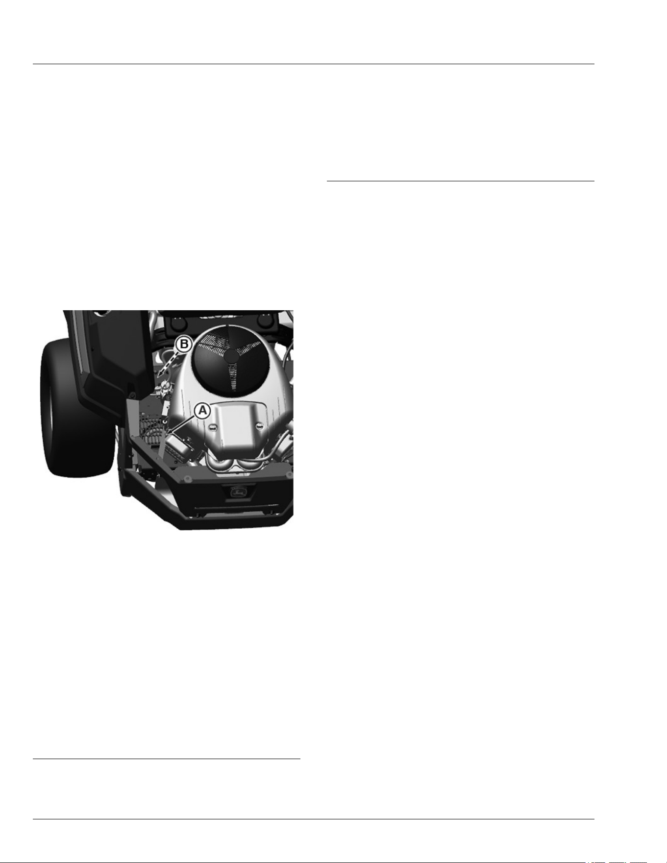
Cleanout Areas
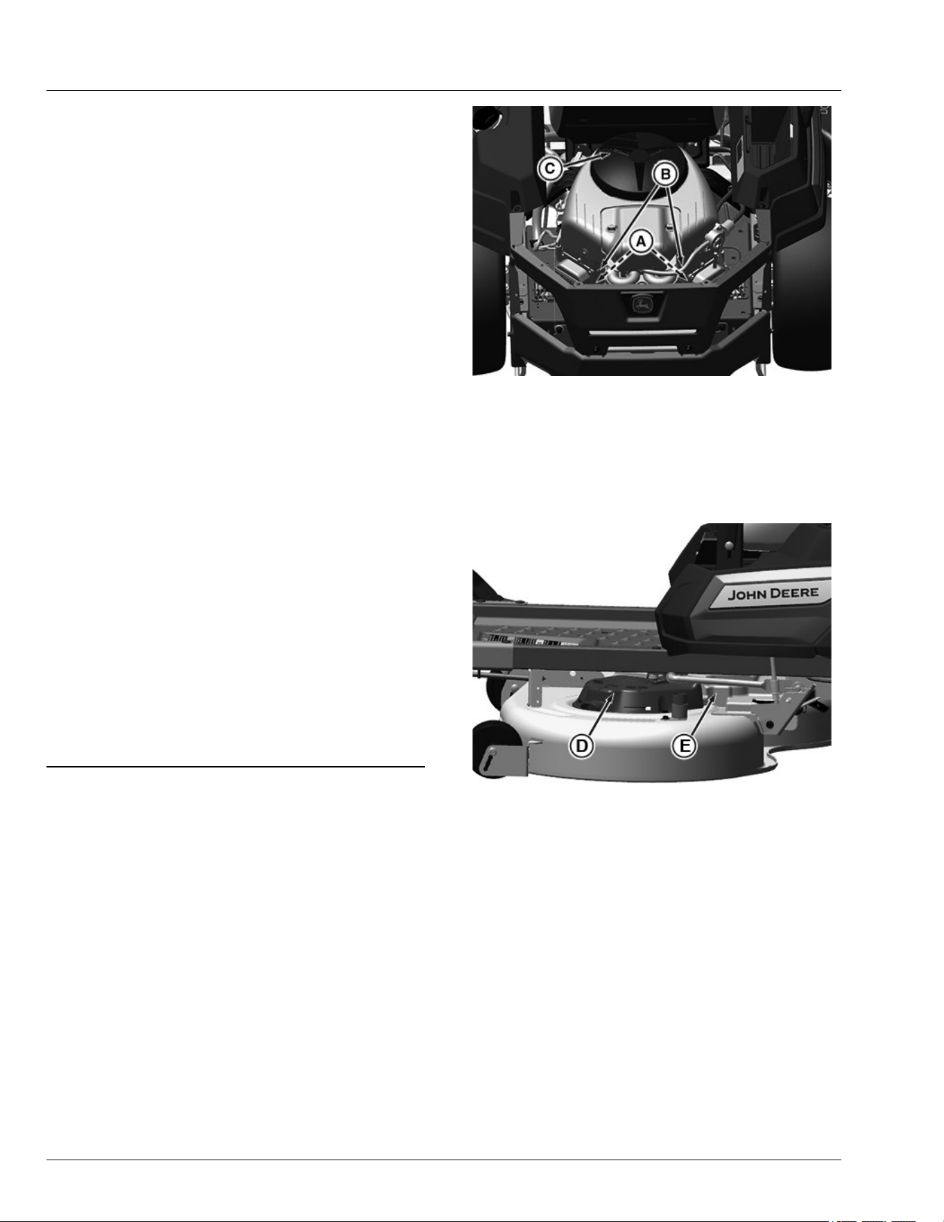
Primary areas that must be inspected and cleaned on
the machine include (see machine service label):
GX535567—UN—19APR22
1.Muer components (A):
- exhaust manifold
- muer pipes
- muer
- muer shield
2.Engine cooling ns (B) and intake screens (C).
APY536701—UN—29APR22
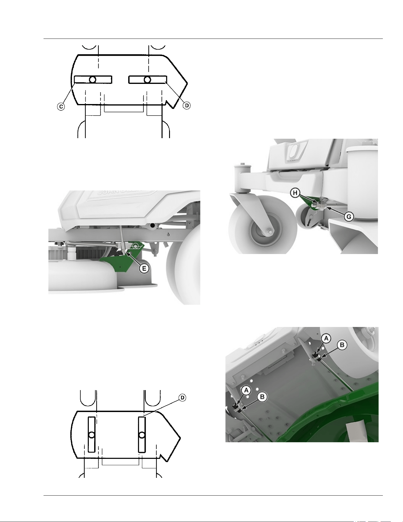
3.Top of the mower deck, under shields (D), including
spindle and belt area (E).
Machine Cleanout
15-1
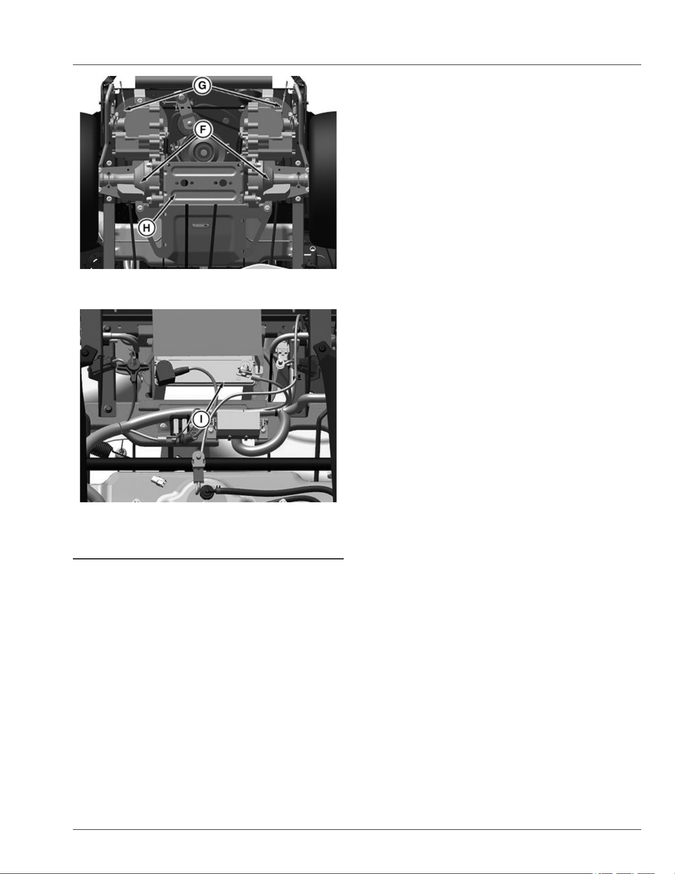
GX535568—UN—19APR22
4.On or near transaxles (F), belt drives, and ns (G)
and cross-strap bracket (H).
GX535569—UN—19APR22
5.Under the seat, including battery (I), and wiring
harness.
GH8XT3T,00008CB-19-29APR22
Machine Cleanout
15-2
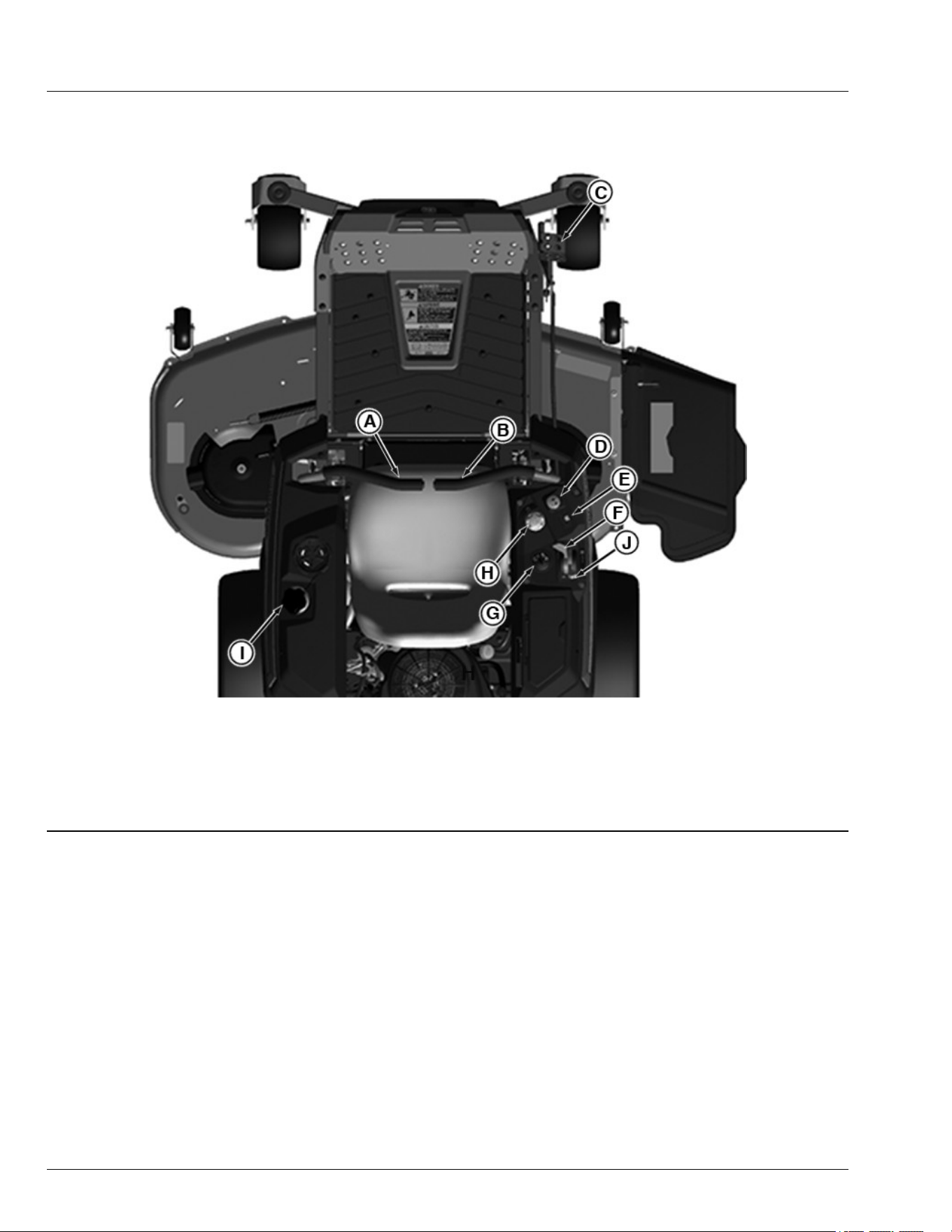
Operator’s Station Controls
APY538561—UN—07JUN22
Operator’s Station Controls: Model May Vary
A—Left Motion Control Lever
B—Right Motion Control Lever
C—Mower Deck Lift Pedal (if equipped)
D—Mower Engagement Switch
E—Hour Meter
F—Throttle Control Lever
G—Key Switch
H—Height-of-Cut Dial Adjustment
I—Fuel Tank Cap
J—Choke Lever (if equipped)
GH8XT3T,00008B6-19-21FEB23
Operating Controls
25-1

Daily Operating Checklist
Check engine oil.
Clean muer area, air intake screens, and mower
deck.
Check brake system.
Check fuel level.
Check under the machine for leaks.
Check safety interlock system.
Check tire pressures.
Check mulch control open/close operation (if
equipped).
Clean mower deck using the washout port after use.
H9PQBYK,000003F-19-12APR22
Avoid Damage to Plastic and Painted
Surfaces
● Do not wipe plastic parts until they are rinsed rst.
Using a dry cloth causes scratches.
● Insect repellent spray damages plastic and painted
surfaces. Do not spray insect repellent near
machine.
● Be careful not to spill fuel on the machine. Fuel
damages surfaces. Wipe up spilled fuel immediately.
MP47322,00F4630-19-02DEC22
Mounting and Dismounting Machine
GX536018—UN—25APR22
NOTE: Do not step on the mower deck when mounting
and dismounting the machine.
1.Mount the machine from the side using the foot plate
(A).
2.Park machine safely before dismounting (See
Parking Safely in the Safety section.)
3.Keep the foot plate clean.
H9PQBYK,0000060-19-25APR22
Adjusting Seat
Adjustable Seat
1. Tip seat forward.
APY69543—UN—25FEB22
2. Remove the knob (A).
3. Slide seat forward or backward to the desired
position.
4. Reinsert the knob (A).
GH8XT3T,00008C6-19-18APR22
Adjusting Motion Control Levers
1. Park machine safely. (See Parking Safely in the
Safety section.)
APY536236—UN—08JUN22
2. To adjust the motion control lever height, refer to the
operator instruction label on the machine front panel
and the instructions that follow.
Operating
30-1
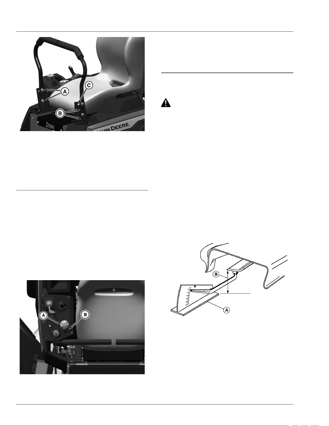
GX535570—UN—19APR22
3. Remove two bolts and nuts and raise or lower each
control lever to your comfort level.
● For highest lever position, use holes (A).
● For lowest lever position, use holes (B).
4. You can also adjust each motion control lever slightly
forward or rearward (C) within slotted holes.
GH8XT3T,00009CB-19-13JUN22
Adjusting Cutting Height
Cutting height can be adjusted from approximately 31––
114 mm (1.25––4.5 in). Refer to the control lever label
on the front platform.
1. Park machine safely. (See Parking Safely in the
Safety section.)
2. Inate tires to the correct pressure. (See tires in the
Specications section.)
3. Depress Mower Deck Lift pedal (if equipped) to
alleviate pressure on Height-of-Cut Dial.
APY69519—UN—08MAR22
4. Rotate dial (A) counterclockwise to raise mower deck
height.
5. Rotate dial (A) clockwise to lower mower deck
height.
6. Rotate dial (A) to index mark (B) to desired mower
deck height.
GH8XT3T,00008AE-19-12JUN25
Adjusting Mower Level
CAUTION: Avoid injury! Rotating blades are
dangerous.
Before adjusting or servicing mower:
● Disconnect spark plug wires or battery
negative (—) cable to prevent engine from
starting
● Always wear gloves when handling mower
blades or working near blades.
NOTE: Mower deck wheels should not contact the
ground when leveling the deck.
1. Park machine safely. (See Parking Safely in the
Safety section.)
2. Inate tires to the correct pressure. (See Tires
pressure in the Specications section.)
3. Position caster wheels to the forward driving position.
4. Set mower to preferred cutting height and lower deck
into the mowing position.
5. Measure mower level (side-to-side).
MXAL42797—UN—09APR13
A convenient leveling gauge (A) (AM130907) is available for
purchase.
a. Position mower blades as follows and measure
from each outside blade tip (B) to the level
surface.
Operating
30-2
MXAL42798—UN—09APR13
b. Turn left blade (C) as shown. Turn the right
blade (D) as shown. Take measurement for both
blades.
The dierence between blade measurements
must not be more than 3 mm (1/8 in).
APY545201—UN—13SEP22
c. If necessary, adjust mower lever by turning nuts
(E) clockwise to raise the side of the mower
deck, or counterclockwise to lower the mower
deck.
NOTE: Ensure that bottom of the lock nut is fully
engaged on the threaded tting to avoid
hardware loosening during operation.
6. Measure mower level (front-to-rear).
MXAL42800—UN—09APR13
a. Turn right blade (D) so that a blade tip points
straight forward.
b. Measure from the blade tip to the surface. Take
measurement for both blades. The front blade
tips must be lower than the rear blade tips
according to the specication listed.
Specication
Front-to-Rear Blade Tip
Variation—Height. . . . . . . . . . . . . . . . . . . . . 3—6 mm (1/8—1/4 in)
c. 42A Mower Deck
APY545202—UN—13SEP22
● Adjust the mower front-to-rear level by
loosening rear nut (G) on the front lift rod.
● Turn front nut (H) clockwise to raise front of
mower or counterclockwise to lower it.
● Tighten rear nut (G) after adjustment is
complete.
d. 48A and 54A Mower Deck
APY597502—UN—06OCT23
● Adjust the mower front-to-rear level by loosening
rear nuts (B) on front lift rods.
● Turn front nuts (A) clockwise to raise front of
mower or counterclockwise to lower it.
● If the lift rod is not tight against both deck hooks,
Operating
30-3
tighten loose side until both sides are tight against
deck hooks.
● Shake the deck slightly to ensure that it has
settled into position.
● Tighten rear nut (B) to specied torque after
adjustment is complete.
Specication
Front Nut—Torque. . . . . . . . . . . . . . . . . . . . . . . . . . .. . . . . 27 N·m
(20 lb·ft)
al64819,1749741365863-19-17OCT25
Adjusting Mower Wheels
CAUTION: Avoid injury! Rotating blades are
dangerous. Before adjusting or servicing
mower:
• Disconnect spark plug wires or battery
negative (-) cable to prevent engine from
starting accidentally.
• Always wear gloves when handling mower
blades or working near blades.
IMPORTANT: Avoid damage! The mower deck can
be damaged if mower wheels are incorrectly
adjusted:
• Wheels must not ride on ground supporting
mower weight.
• Check wheel adjustment each time cutting
height is changed.
1. Park machine safely on a level surface. (See Parking
Safely in the Safety section.)
2. Inate tires to correct pressure.
3. Move the motion control lever outward to lock
machine in start/shutdown position.
4. Adjust mower wheels to the correct height:
42A, 48A, and 54A Mower Decks
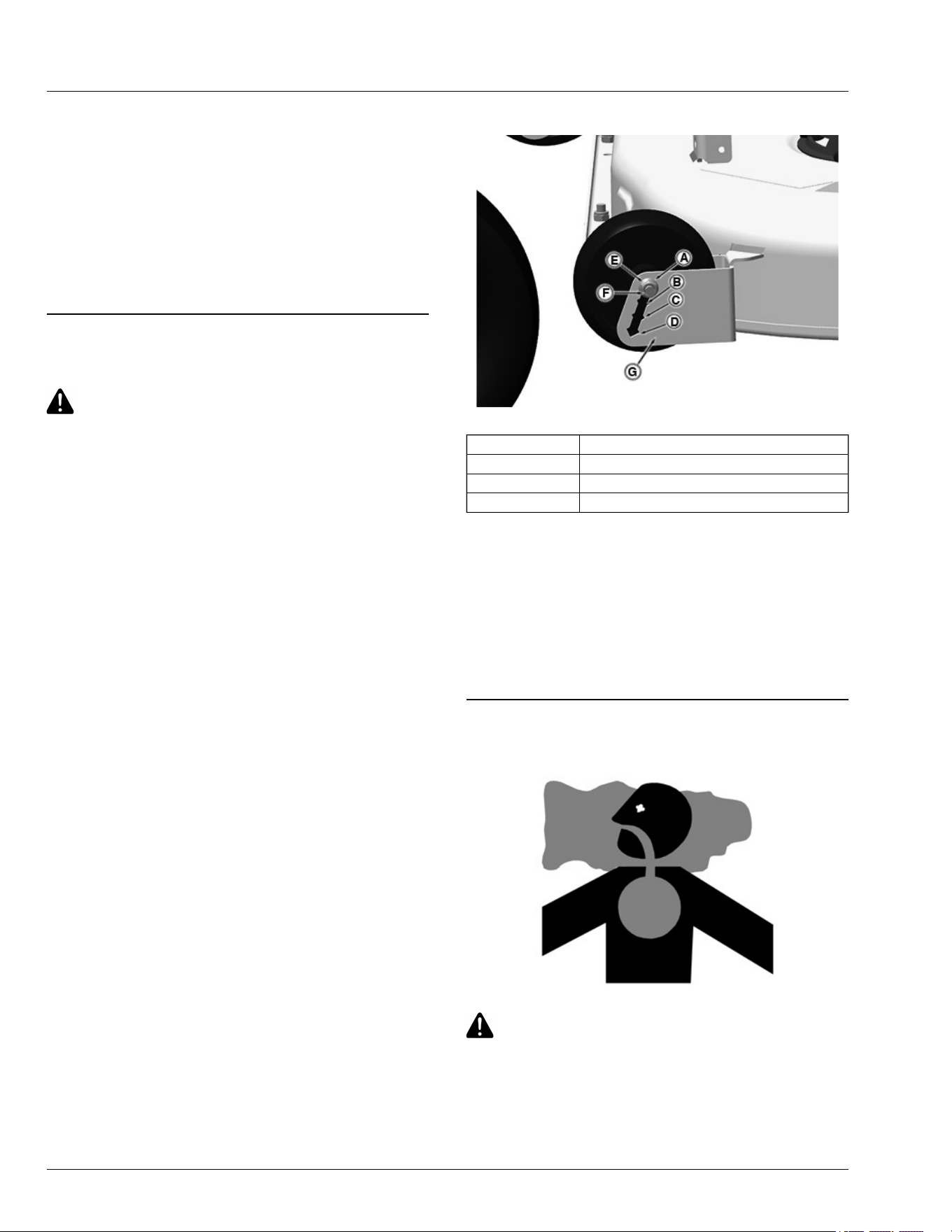
APY69526—UN—07MAR22
Position 1 (A) 31- 38 mm (1.25 — 1-1/2 in) Height of Cut
Position 2 (B) 38 - 50 mm (1-1/2 — 2 in) Height of Cut
Position 3 (C) 50 - 76 mm (2 — 3 in) Height of Cut
Position 4 (D) 76 - 101 mm (3 — 4.5 in) Height of Cut
● Remove nut (E). Pull carriage bolt (F) out until end of
bolt clears the outer wall of the gauge wheel bracket
(G), then slide bolt and wheel assembly to the
desired position. Push bolt back through outer wall of
bracket. Install nut (E) and tighten to specication.
Specication
Mower Wheel Nut—Torque. . . . . . . . . . . . . . . . . . 24 N·m (18 lb·ft)
GH8XT3T,00008D3-19-06JUN22
Testing Safety Systems
MXAL42804—UN—09APR13
CAUTION: Avoid injury! Engine exhaust fumes
contain carbon monoxide and can cause
serious illness or death.
Do not run an engine in an enclosed area, such
as a garage, even with doors or windows
opened.
Operating
30-4

Move the machine to an outside area before
running the engine.
The safety systems installed on your machine should be
checked before each machine use. Be sure that you
have read the machine operator manual and are familiar
with the operation of the machine before performing
these safety system checks.
Use the following checkout procedures to check for
normal operation of machine.
If there is a malfunction during one of these procedures,
do not operate machine. See your dealer or other
service provider for service.
Perform these tests in a clear open area. Keep
bystanders away.
MP47322,00F4637-19-11JUL25
Testing Park Brake Switch
1.Park machine safely. (See Parking Safely in the
Safety section.)
2.Sit on seat.
3.First test:
a. Move right motion control lever inward to the
neutral position.
b. Turn key to the START position.
Result: Engine must not turn over. If engine turns
over, there is a problem with your safety interlock
circuit.
4.Return right motion control lever to fully outward
position.
5.Second Test:
a. Move left motion control lever inward to the neutral
position.
b. Turn key to the START position.
Result: Engine must not turn over. If engine turns
over, there is a problem with your safety interlock
circuit.
6.Return left motion control lever to fully outward
position.
GH8XT3T,00009BA-19-13JUN22
Testing Park Brake
1. Park machine safely (See Parking Safely in the
Safety section.)
2. Lock the park brake by moving the motion control
levers fully outward.
3. Engage bypass valve control.
4. Try to push machine manually.
Result: Park brake must prevent machine from moving.
If machine moves, see your John Deere dealer or other
service provider for service.
NOTE: When testing is complete, disengage bypass
valve control prior to returning machine to service.
GH8XT3T,00009BB-19-17OCT25
Testing Mower Engagement (PTO) Switch
CAUTION: Avoid injury! The mower blades
should stop in approximately ve seconds
when the mower or PTO is disengaged.
If you believe that your blades may not be
stopping in that period of time, take your
machine to your John Deere dealer or other
service provider where they can safely check
and service your machine.
1. Park machine safely. (See Parking Safely in the
Safety section.)
2. Sit on seat.
3. Lock the park brake by moving motion control levers
fully outward.
4. Pull mower engagement (PTO) switch up to engage.
5. Turn key switch to the START position.
Result: Engine must not turn over. If engine turns over,
there is a problem with your safety interlock circuit.
H9PQBYK,0000043-19-17OCT25
Testing Seat Switch
1. Park machine safely. (See Parking Safely in the
Safety section.)
2. First test:
a. Lock the park brake by moving the motion
control levers fully outward.
b. Sit on seat.
c. Start engine.
d. Move motion control levers inward to neutral
position.
e. Pull mower engagement switch (PTO) up to
engage.
f. Raise up slightly o the seat. Do not get o
machine.
Result: The machine should stop. If engine
does not stop, there is a problem with your
safety interlock circuit.
g. Return to sitting position in seat.
Operating
30-5
h. Return motion control levers to the fully outward
position.
i. Push mower engagement switch (PTO) down to
disengage.
j. Turn machine o.
3. Second test:
a. Lock the park brake by moving the motion
control levers fully outward.
b. Sit on seat.
c. Start engine.
d. Raise up slightly o the seat. Do not get o
machine.
Result: Engine should continue to run. If engine
stops, there is a problem with your safety
interlock circuit.
e. Return to sitting position in seat.
f. Turn machine o.
H9PQBYK,0000045-19-13JUN22
Using Park Brake
CAUTION: Avoid injury! Children or bystanders
may attempt to move or operate an unattended
machine. Always lock the park brake and
remove the key before leaving the machine
unattended.
Locking Park Brake
APY536680—UN—27APR22
To lock the park brake, move motion control levers (A)
fully outward.
Unlocking Park Brake
APY536679—UN—07JUN22
To unlock the park brake, move motion control levers
(A) inward to neutral position.
GH8XT3T,00008B4-19-10JUN22
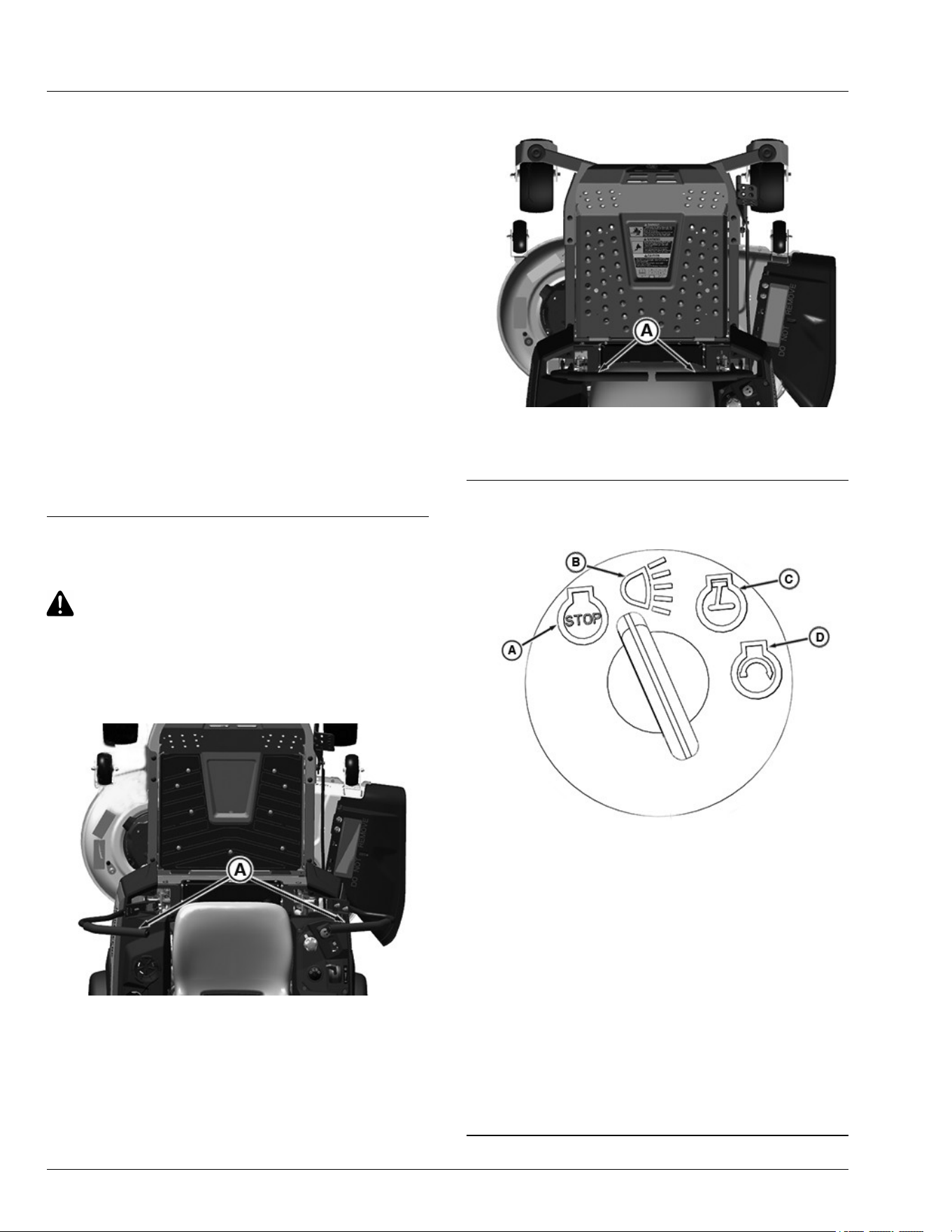
Using Key Switch
APY69525—UN—07MAR22
A—STOP Position
B—LED Light (if equipped
C—Run Position
D—START Position
● A - STOP (o) position - With key in the STOP
position, all switched power is o, and engine should
not run.
● B - LED light - Turn key from STOP to this position.
LED light will be on.
● C - Run (on) position - Turn key from STOP to this
position, and all switched power circuits will be on.
● D - START position - Turn key to start position to
crank the engine. Release key after engine has
started and it will automatically return to the on
position. The engine continues to run.
GH8XT3T,00008B5-19-17FEB23
Operating
30-6

Using Mower Engagement Switch
● To Engage Mower - Pull mower engagement knob
up.
● To Disengage Mower - Push mower engagement
knob down.
MP47322,00F463F-19-15MAR13
Using the Hour Meter
● The hour meter shows the number of hours the
engine has run. The hour meter does not accumulate
hours with the engine o when the key is in the run
position. Use the hour meter to determine when your
machine has reached the recommended service
intervals.
● Turn the key to STOP position when not using the
machine.
● Hour meter cannot be reset.
MP47322,00F4640-19-05JUN15
Using the Motion Control Levers
CAUTION: Avoid injury! Learn the use of the
motion control levers and practice at half
throttle until becoming procient and
comfortable with the operation of the machine.
Do not move motion control levers from
forward to reverse or reverse to forward
position rapidly. Sudden direction changes
could cause loss of control or damage the
machine.
Before using the machine, become familiar with the
motion control levers and how they respond. It is
essential to know how the machine accelerates, steers,
and stops.
The functions of the motion control levers are:
● Dual function neutral position.
● Steering.
● Acceleration.
● Braking.
Start/Shutdown Position
APY536680—UN—27APR22
● Motion control levers must be placed fully outward
(A). This position engages the park brake and allows
the operator to start the engine.
● Forward and reverse movement of the motion control
levers is prevented when levers are moved to the
start/shutdown position.
● Operator can exit mower with the engine running
when the mower engagement switch is disengaged
and the motion control levers are fully outward.
● Motion control levers must be fully outward to safely
enter and exit the operator’s seat.
Neutral Position
GX536019—UN—25APR22
● Machine speed, motion, and direction can be
controlled when the engine is running and motion
control levers are in the neutral position (C).
● To stop the machine for an emergency, move the
motion control levers quickly back to the neutral
position.
Forward and Reverse Travel
Straight forward and reverse travel takes practice. If the
machine does not track in a straight line when going
Operating
30-7

forward or reverse, the motion control lever tracking
may need adjusting.
1. Move throttle lever to the mow position.
2. Move both motion control levers from the start/
shutdown position inward to the neutral position.
3. Move the motion control levers forward to begin
forward travel.
4. Move the motion control levers rearward to begin
reverse travel.
5. To stop travel, move motion control levers back to the
neutral position.
Forward Travel
GX536021—UN—25APR22
Gradually move both motion control levers evenly
forward (A) from neutral. To speed up, move the levers
farther forward. To slow down smoothly, slowly move the
levers toward neutral.
Reverse Travel
GX536020—UN—25APR22
Look down and behind, then gradually move both
motion control levers evenly rearward (B) from neutral.
To speed up, move the levers farther rearward. To slow
down smoothly, slowly move the levers toward neutral.
Left Turn
GX536022—UN—25APR22
1. To turn slightly to the left, push right control lever (C)
further forward than the left control lever (D).
APY69540—UN—28APR22
2. To turn sharply to the left, push right control lever (C)
forward and pull left control lever (D) rearward at the
same time.
Operating
30-8

Right Turn
GX536023—UN—25APR22
1. To turn slightly to the right, push left control lever (D)
further forward than the right control lever (C).
APY536684—UN—28APR22
2. To turn sharply to the right, push left control lever (D)
forward and pull right control lever (C) rearward at
the same time.
GH8XT3T,00009BC-19-10JUN22
Using Dual Levers (If Equipped)
GX535573—UN—07JUN22
Dual lever for Model Z320R, Z320M
1. Pull the choke lever (A) down when starting a cold
engine.
2. After engine has started, push the choke lever (A) up
completely to the previous position.
3. Push the throttle lever (B) down to increase the
engine speed.
4. Pull the throttle lever (B) up towards tortoise as
shown in graphics to decrease the engine speed.
GH8XT3T,00008D8-19-12JUN22
Starting the Machine
CAUTION: Avoid injury! Engine exhaust fumes
contain carbon monoxide and can cause
serious illness or death.
Do not run an engine in an enclosed area, such
as a garage, even with doors or windows
opened.
Move the machine to an outside area before
running the engine.
1. Sit on the operator’s seat.
2. Set both motion control levers to the start/shutdown
position.
3. Push the mower engagement knob to disengage the
mower.
4. Adjust throttle lever to set engine speed:
● Cold Start: Set throttle control to the Start
position, full throttle Use the choke control as
necessary (if equipped).
● Warm Start: Set throttle control to the mow
position, full throttle.
Operating
30-9
IMPORTANT: Avoid damage! Starter may be
damaged if the starter is operated for more than
20 seconds at a time:
NOTE: Wait two minutes before trying again if engine
does not start.
5. Turn key switch to the START position.
6. After engine starts, release key switch to the RUN
position, disengage the choke control (if equipped),
and move throttle to the mow position, full throttle.
IMPORTANT: Avoid damage! Unnecessary engine
idling may cause engine damage. Excessive
idling can cause engine overheating, carbon
buildup, and poor performance.
7. Allow the engine to warm up for 20 seconds.
8. Set both motion control levers to the neutral position
from the start/ shutdown position.
GH8XT3T,00008B1-19-17FEB23
Engaging Mower
CAUTION: Avoid injury! Clear mowing area of
all bystanders when operating this machine.
Thrown objects could cause serious injury or
death.
Keep hands and feet away from blades and
discharge opening.
Do not mow in reverse unless necessary.
1. Adjust mower to desired cutting height.
2. Start engine.
3. Move both motion control levers to the neutral
position from the start/shutdown position.
4. Set throttle lever to the START/MOW position, full
throttle.
5. Pull mower engagement switch up to engage mower.
NOTE: The travel speed and turn rate vary with the
amount that the control levers are moved.
6. Push motion control levers forward slowly. Mow at
safe travel speed.
GH8XT3T,00008B2-19-18MAR22
Using MulchControl (If Equipped)
CAUTION: Avoid injury! Rotating belts and
blades are dangerous.
1. Park machine on a at, level surface.
2. Disengage mower blades.
3. Lock the park brake.
4. Wait for all moving mower deck parts to stop before
you leave the operators station.
APY24916—UN—11DEC19
5. Rotate lever clockwise (A) to close or
counterclockwise (B) to open.
SB31882,0000443-19-09JUN22
Unplugging Mower
CAUTION: Avoid injury! Do not attempt to
unplug attachment with machine running.
Rotating blades are dangerous. Shut o the
engine and remove the key before getting o
the seat to inspect the machine and attachment.
Thrown objects can cause serious injury. Make
sure that all machine parts are stopped before
raising hopper top or removing chutes.
1. Park machine safely. Wait for all moving parts to stop
before you leave the operator’s station to inspect
machine.
2. Check under mower deck and discharge chute for
debris.
3. Clear all debris before using mower.
4. If plugging occurs, switch to open mode to allow
some grass to discharge.
OUO2004,0000AF8-19-29JAN21
Stopping the Machine
1. Stop machine on a level surface, not on a slope.
2. Push the mower engagement switch down to
disengage mower
3. Throttle position must remain in the full throttle
position to avoid backring at shutdown.
Operating
30-10
4. Lock the park brake by moving the motion control
levers fully outward.
5. Turn ignition key to STOP (o) position.
CAUTION: Avoid injury! Children or bystanders
may attempt to move or operate an unattended
machine.
Always lock the park brake and remove the key
before leaving the machine unattended.
6. Remove key.
H9PQBYK,0000047-19-17FEB23
Move Machine by Hand
CAUTION: CAUTION: Avoid injury! When the
bypass valve is open, the machine will have
unrestricted motion.
● Do not open the bypass valve when the
machine is stopped on an incline to prevent
it from going downhill out of control.
IMPORTANT: Avoid damage! Transmission damage
occur if the machine is towed or moved
incorrectly:
● Move machine manually.
● Do not use another vehicle to move machine.
● Do not tow machine.
When moving the machine without starting the engine,
always use the bypass valves:
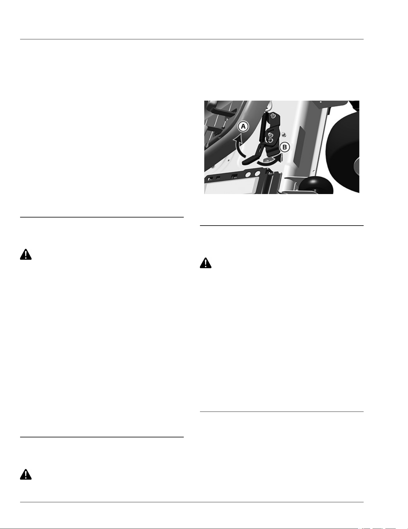
APY538834—UN—07JUN22
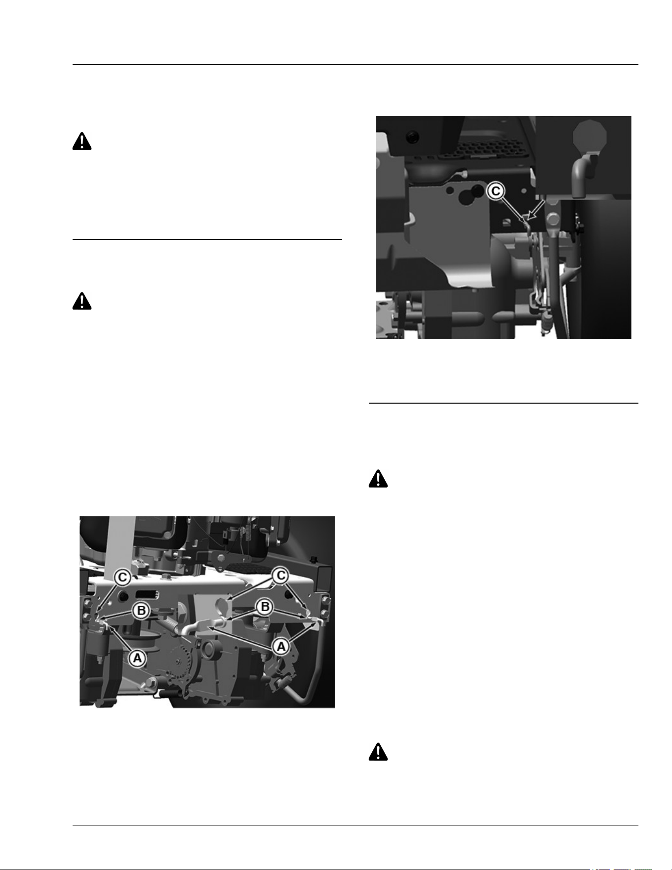
1. Pull bypass control rods (A) rearward through the key
hole slot and place the collar (B) into the detent slot
(C) to engage bypass valve.
2. Release park brake.
3. Push machine to desired location and lock park
brake.
NOTE: The bypass control rods should be disengaged
before starting and operating the machine.
APY536234—UN—25APR22
4. Move both bypass control rods from their detent slot
and push back the control rods to the original position
(C).
GH8XT3T,00009BD-19-19FEB23
Unplugging Mower, Bagger, or Material
Collection System
CAUTION: Avoid injury! Do not attempt to
unplug attachment with the machine running.
● Rotating blades are dangerous. Shut o the
engine and remove the key before getting o
the seat to inspect the machine and
attachment.
● Thrown objects can cause serious injury.
Make sure that all machine parts are stopped
before raising hopper top or removing
chutes.
Checking for Plugging While Driving
If grass builds up in the front of the mower discharge
chute, check for plugged chute or problems with blower
assembly (if equipped).
If there is a trail of clippings behind mower or clippings
blow to the side, check for plugged chute, full collector
bags, or problems with blower assembly.
Removing Debris from Inspection Points:
CAUTION: Avoid injury! Do not use hands or
feet to clear plugged mower deck or blower
assembly. Stored energy can cause blades to
rotate.
Operating
30-11
1. Park machine safely. Wait for all moving parts to stop
before getting o to inspect machine.
2. Open hopper cover. Check chute outlet.
3. Remove chute from the mower deck or blower
assembly. Check chute inlet.
4. Check under the mower deck for debris.
MP47322,00F4646-19-10JUL20
Using Wash Port to Clean Mower Deck
NOTE: Follow this procedure after each use to prevent
buildup and remove corrosive lawn chemicals.
1. Park machine safely. (See Parking Safely in the
Safety section).
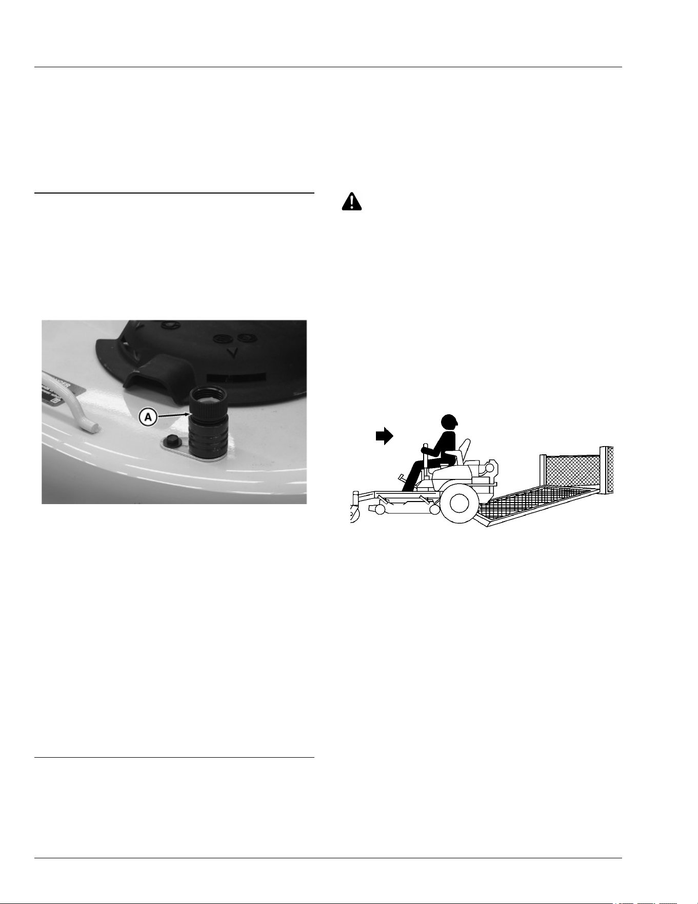
MX101450—UN—29APR20
2. Attach quick-coupler to the garden hose.
3. Attach garden hose with the quick-coupler to wash
port (A) on the mower deck.
4. Turn on water.
5. Start engine.
6. Run at full throttle.
7. Engage mower blades.
8. Flush water under the deck for approximately one
minute.
9. Disengage mower blades.
10. Stop engine.
11. Turn o water and remove garden hose and quick-
coupler from the wash port.
SB31882,000040A-19-06MAY20
Transport Machine on Trailer
NOTE: Trailer capacity must exceed combined machine
weight and attachment weight. (See Specications
section in Operator’s Manual.)
Ensure that trailer has all the necessary lights and signs
required by law.
CAUTION: Avoid injury! Use extra care when
loading or unloading the machine onto a trailer
or truck. Machine wheels can go o the ramp or
trailer, causing the machine to tip over.
● To load, back up slowly and in a straight line.
Keep wheels away from drop-os and edges.
● Do not use two separate loading ramps. Use
full width loading ramp at least 30 cm (12 in)
wider than machine to keep caster wheels
from going o the ramp edge.
● Use a trailer with sides.
1. Park trailer on level surface.
2. Fully raise mower deck before driving machine onto
trailer.
MXAL42817—UN—09APR13
3. Back machine onto heavy-duty trailer with full-width
ramp.
4. Lower mower deck completely.
5. Lock park brake.
6. Turn o machine and remove key.
Operating
30-12

APY536235—UN—25APR22
7. Fasten front of machine at both sides of the frame at
points (A) to trailer with heavy-duty straps, chains, or
cables. Straps must be directed down, forward, and
outward from machine.
APY69528—UN—07MAR22
8. Fasten rear of machine at both sides of frame at
points (B) to trailer with heavy-duty straps, chains, or
cables. Straps must be directed down, rearward, and
outward from machine.
GH8XT3T,00009BE-19-12JUN25
Transporting Material Collection System (If
Equipped)
If the material collection system is left on the machine
during transport, follow these guidelines when trailering
the unit:
● Empty the cloth bags and remove them from the
hopper. Full bags add extra weight which can
overstress the hopper frame on rough roads. At road
travel speeds, wind can cause premature wear of the
cloth bags.
● Make sure that the hopper cover is latched securely
to the hopper frame.
● If the unit is transported over long distances or at
high speeds, remove the rear bagger or power ow
chute before transport.
TH84124,000020A-19-10APR19
Towing Loads
IMPORTANT: Avoid damage! Towing excessive
trailer loads can stress drivetrain components.
To avoid damage to drivetrain components, use
the following guidelines.
● Do not exceed maximum towing capacity of 113.4 kg
(250 lbs).
● Do not exceed maximum tongue weight of 45.4 kg
(100 lbs).
● Always run tractor at full throttle when towing loads.
● Avoid inclines greater than a 10 degree slope while
towing to avoid damage to the pulling machine. Use
the Slope Guide located in this operator’s manual to
ensure proper machine towing operation. See
Operating on Slopes in the Safety section for
additional information.
● Avoid making tight turns. Make wide turns to avoid
jack-kning.
● Travel slowly and allow extra stopping distance.
SB31882,0000444-19-02DEC22
Mowing Tips
● Mow grass with throttle lever in the full fast / mow
position.
● Mow grass when it is dry.
● Keep mower deck and discharge chute clean.
● Mow with sharp blades.
● Properly level mower deck for a smooth cut.
● Mow grass frequently.
● Use a travel speed that ts the conditions:
- Mow tall or wet grass twice. With the rst pass, cut
grass halfway to desired height. With the second
pass, cut to the desired height.
- Travel slowly when mowing tall or thick grass.
- Avoid damaging grass by slipping or skidding
machine drive wheels. Practice smooth control
lever movements.
- When performing sharp turns, do not allow inside
machine drive wheel to stop and twist on grass.
MG39705,00005BB-19-09JUN21
Operating
30-13

Blade Choices
Several types of blades are available for Z300 series
mowers:
42A , 48A, and 54A Decks
● Dedicated Side discharge blades. These blades are
designed for optimal performance when side
discharging, and are installed on Z300 Series 42A,
48A, and 54A mowers when shipped from the
factory.
● Dedicated Mulching blades. These blades are
designed for optimal performance when used with a
mulch cover or mulch plug installed.
● Dedicated Bagging blades (42A Deck Only). These
blades are designed for optimal performance when
used with a Z300 series bagger.
MX52301,0000EFF-19-28MAY20
Operating
30-14

Servicing Your Machine
IMPORTANT: Avoid damage!
Operating in extreme conditions may require
more frequent service intervals:
● Engine components may become dirty or
plugged when operating in extreme heat,
dust or other severe conditions.
● Engine oil can degrade if machine is
operated constantly at slow or low engine
speeds or for frequent short periods of time.
High-pressure washing can cause damage to
machine components. It is recommended that
your vehicle be washed by hand or with a
garden hose using mild soap.
Avoid spraying water with any great force near
or into the following places:
● Air intake
● Electrical connections (including battery
compartment)
● Wheel bearings
● Radiator (if equipped)
● Warning labels
● Other labels
● Ignition switch
● Instrument panel (gauges and switches)
● Breather/tube vents
● Mower spindles
● Mower idler bearings
● Transmission cooling fans
Please use the following timetables to perform routine
maintenance on your machine.
Park the vehicle safely. (See Park Safely in the SAFETY
Section.)
OUMX068,00006EF-19-22NOV16
Service Intervals
Every 8 Hours or Daily
● Check Engine Oil.
● Clean muer area, air intake screens, and mower
deck.
● Check brake system.
● Check fuel level.
● Clean mower deck with washout port after use.
● Check under machine for leaks.
● Check safety interlock system.
● Check tire pressure.
Yearly or 50 Hours (Whichever Comes First)
● Check mower deck level. Level if necessary.
● Change engine oil. (10W30)
● Replace engine oil lter.
● Lubricate mower deck spindles and idler arm.
Every 100 Hours or Annually (Whichever Comes
First)
● Replace air lter, fuel lter, and spark plugs.
● Clean engine cooling ns.
● Check mower belt. Replace if necessary.
● Sharpen / replace mower blades.
● Clean underside of mower deck.
● Check tire pressure.
● If there is debris that cannot be blown out, remove
blower housing for complete cleaning.
Every 200 Hours
● Check / adjust engine valve clearance. See your
John Deere dealer or other service provider for this
service.
SDHTXN6,1746551603139-19-06MAY25
Service Intervals
35-1
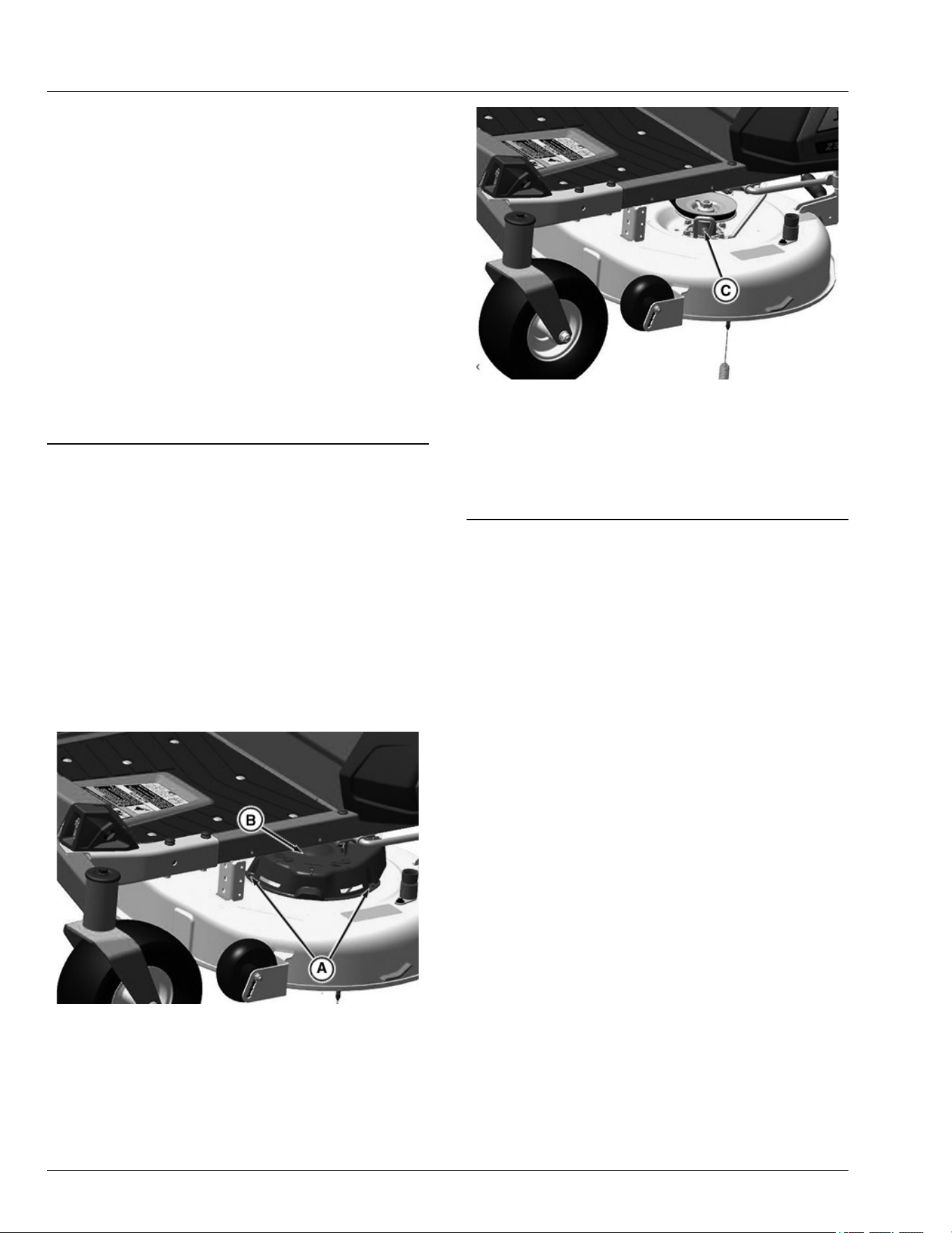
Grease
IMPORTANT: Avoid damage! Use recommended
John Deere greases to avoid component failure
and premature wear.
The following grease is recommended for service:
● John Deere Multi-Purpose HD Lithium Complex
Grease
● Grease-Gard Premium Plus
Not all grease types are compatible; John Deere does
not recommend mixing greases. If using any product
other than the recommended grease in service, purge
any remaining grease from the system before
application. If not practical, grease twice as often until all
old grease is purged from the system.
OUMX068,0000642-19-12APR24
Lubricating Mower Deck Spindles
NOTE: Removal of belt shields is not necessary to
lubricate the spindles.
1. Park machine safely. (See Parking Safely in the
Safety section.)
2. Lower mower deck fully.
3. Remove the mower deck foot plate. (See removing
and installing mower deck foot plate in the Service
Mower section.)
42A Mower Deck
GX535576—UN—21APR22
● Remove two screws (A) and left spindle cover (B).
GX535581—UN—21APR22
● Lubricate left spindle grease tting (C) with two
pumps of grease at the specied interval.
● Install the left spindle cover with two screws.
● Repeat steps to lubricate the right mower deck
spindle.
GH8XT3T,00008DF-19-10NOV22
Service Lubrication
40-1
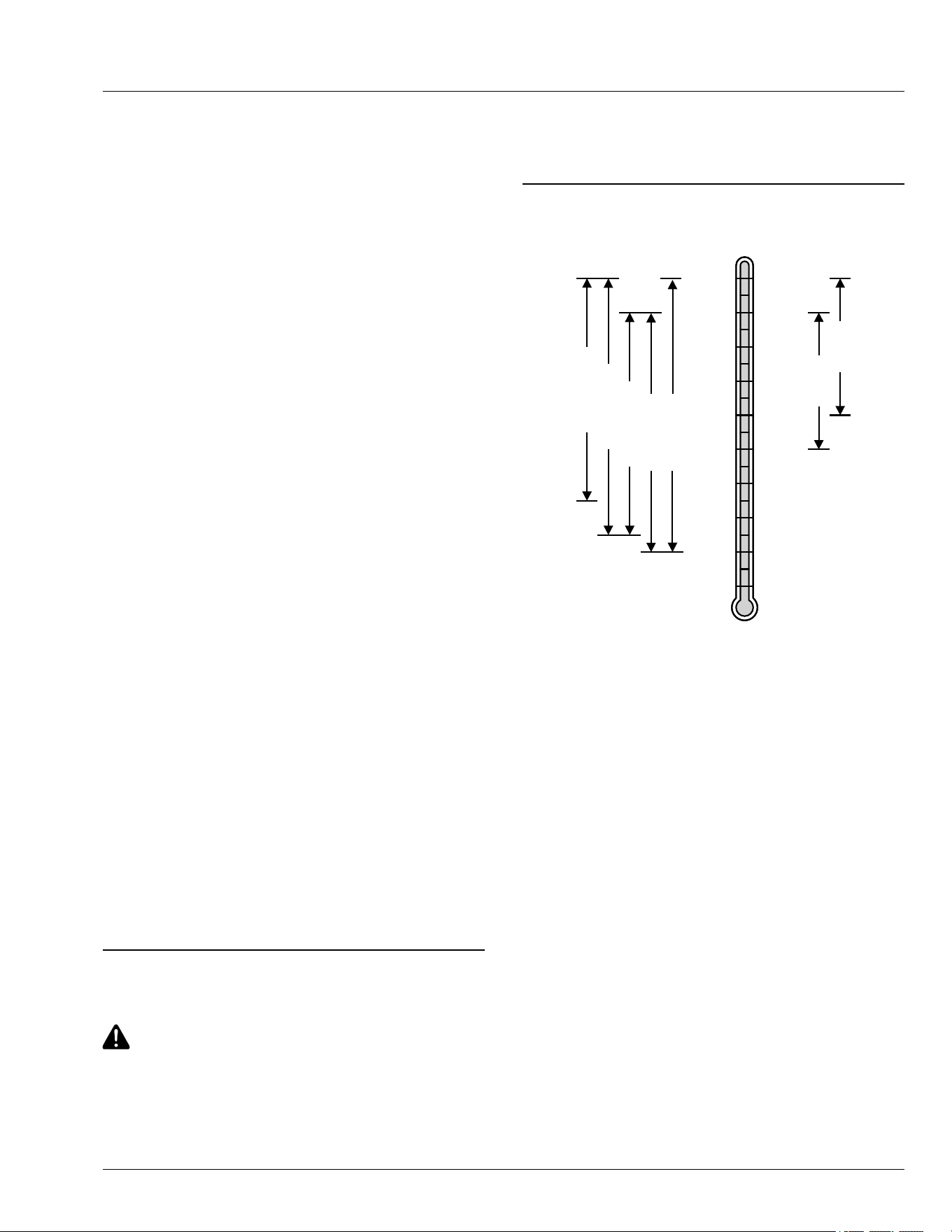
Emissions Service Information
Within the warranty period, John Deere will reimburse
reasonable service costs incurred at service providers
outside the John Deere authorized network only in an
unsafe, emergency condition if an authorized John
Deere dealer is not available and the failure does not
arise from the owner’s misuse or failure to perform
required maintenance. An emergency situation exists
under this section if, after 30 days, the authorized John
Deere network is unable to perform the repairs or
source replacement parts.
Emission Control System Certication Label
NOTE: Tampering with emission controls and
components by unauthorized personnel may result
in severe nes or penalties. Emission controls and
components can only be adjusted by EPA and/or
CARB authorized service centers. Contact your
John Deere Retailer concerning emission controls
and component questions.
The presence of an emissions label signies that the
engine has been certied with the United States
Environmental Protection Agency (EPA) and/or
California Air Resources Board (CARB).
The emissions warranty applies only to those engines
marketed by John Deere that have been certied by the
EPA and/or CARB; and used in the United States and
Canada in o-road mobile equipment.
Altitude Adjustment (Gasoline or Propane
Converted Engines Only)
If your engine features a carburetor it is calibrated by the
engine manufacturer and is not adjustable.
If your engine is operated at altitudes below 610 m
(2,000 ft.), a high altitude carburetor jet kit is not
required. If your engine is operated at altitudes above
610 m (2,000 ft.), a high altitude carburetor jet kit may
be required for proper engine performance and
emissions control. Operating the engine with the wrong
carburetor conguration at a given altitude may increase
the engine’s emissions and decrease fuel eciency and
performance.
See a qualied service provider for details on jet kit
requirements for your specic product.
TC00531,00000EC-19-20FEB25
Avoid Fumes
CAUTION: Avoid injury! Engine exhaust fumes
contain carbon monoxide and can cause
serious illness or death.
Do not run an engine in an enclosed area, such
as a garage, even with doors or windows
opened.
Move the machine to an outside area before
running the engine.
MP47322,00F4652-19-13JAN15
Gasoline Engine Oil
SAE 5W-40
SAE 30
SAE 40
SAE 5W-30
SAE 10W-30
SAE 10W-40
SAE 15W-40
0
o
C
-10
o
C
-20
o
C
-30
o
C
-40
o
C
10
o
C
20
o
C
30
o
C
40
o
C
50
o
C
32
o
F
14
o
F
-4
o
F
-22
o
F
-40
o
F
50
o
F
68
o
F
86
o
F
104
o
F
122
o
F
TS1744—UN—25AUG20
Oil Viscosities for Air Temperature Ranges
Use oil viscosity based on the expected air temperature
range during the period between oil changes.
Using single viscosity grade oils such as SAE 30 or SAE
40 can reduce oil consumption in air cooled engines.
The following oils are approved:
● John Deere Plus-50™ II
● John Deere Turf-Gard™
Other oils may be used if they meet one or more of the
following:
● ILSAC GF-6A
● API Service Category SP
● API Service Category SN
● API Service Category SM
● API Service Category SL
● API Service Category SJ
● ACEA Oil Sequence A3/B3
● ACEA Oil Sequence A3/B4
● ACEA Oil Sequence A5/B5
● ACEA Oil Sequence C5
Plus-50 is a trademark of Deere & Company
Turf-Gard is a trademark of Deere & Company
Service Engine
45-1
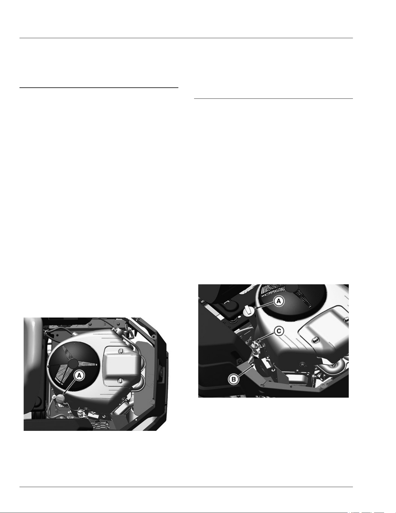
● ACEA Oil Sequence C4
● ACEA Oil Sequence C3
● ACEA Oil Sequence C2
● ACEA Oil Sequence C1
DX,ENOIL2-19-15JUL20
Checking Engine Oil Level
IMPORTANT: Avoid damage! Failure to check the oil
level regularly could lead to serious engine
problems if oil level is out of the operating
range:
● Check oil level before operating.
● Check oil level when the engine is cold and
not running.
● Keep oil level between the dipstick marks.
● Shut o engine before adding oil.
NOTE: Check oil twice a day if you run engine over 4
hours in a day.
Make sure that engine is cold when checking
engine oil level.
1. Park machine safely. (See Parking Safely in the
Safety section.)
IMPORTANT: Avoid damage! Dirt and contamination
can enter engine when checking oil level. Clean
area around dipstick before loosening or
removing.
2. Clean area around the dipstick to prevent debris from
falling into crankcase.
GX535578—UN—19APR22
3. Remove dipstick (A). Wipe with clean cloth.
4. Install and tighten the dipstick.
5. Remove dipstick.
6. Check oil level on dipstick. Oil must be between ADD
and FULL marks.
7. If oil level is low, add oil to bring oil level no higher
than FULL mark on dipstick. Do not overll.
8. Install and tighten the dipstick.
H9PQBYK,0000059-19-21APR22
Changing Conventional Engine Oil and
Filter
IMPORTANT: Avoid damage! Operating in extreme
conditions may require more frequent service
intervals:
● Engine components may become dirty or
plugged when operating in extreme heat,
dust, or other severe conditions.
● Engine oil can degrade if machine is
operated constantly at slow or low engine
speeds or for frequent short periods of time.
1. Run engine to warm oil.
2. Park machine safely on the level surface. (See
Parking Safely in the Safety section.)
IMPORTANT: Avoid damage! Dirt and contamination
can enter engine when checking oil level. Clean
area around dipstick before loosening or
removing.
GX535579—UN—19APR22
3. Clean area around dipstick (A) to prevent debris
from falling into crankcase.
4. Loosen dipstick (A). Disconnect oil drain hose (B)
from the side of the engine.
5. Remove the oil drain cap (C). Carefully lower the
quick oil drain into an approved container until the
oil has drained completely.
Service Engine
45-2
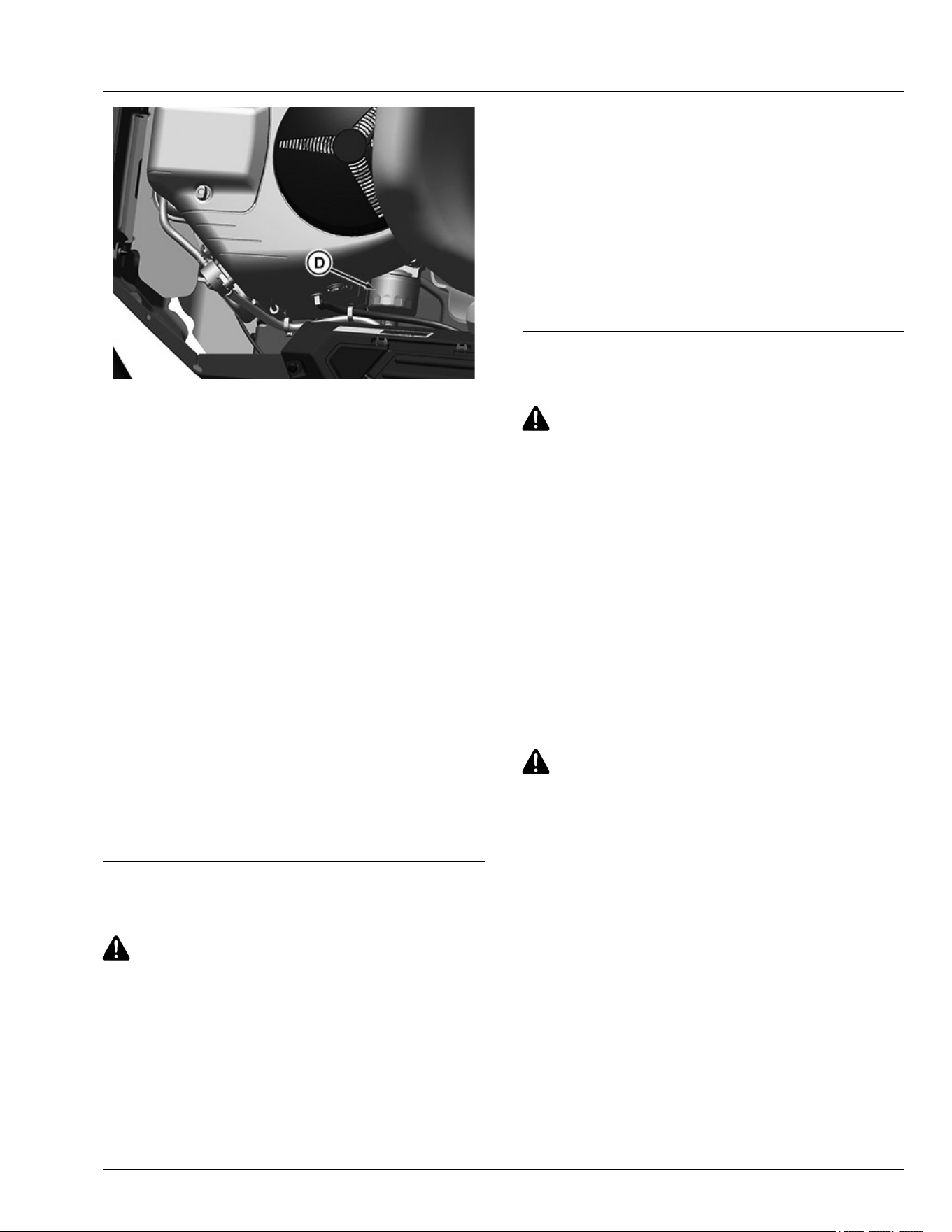
GX535580—UN—19APR22
6. Wipe dirt from around the oil lter (D). Place a drain
pan under the oil lter, and remove lter.
7. Wipe up any dripped oil from the oil lter on the
engine pan.
8. Put a light coat of fresh, clean oil on the new lter
gasket.
9. Install replacement oil lter by turning oil lter to the
right (clockwise) until the rubber gasket contacts
lter base. Tighten lter an additional one-half turn.
10. After oil has drained, install the drain cap (C) and
attach drain hose assembly (B) to side of engine.
11. Add oil no higher than FULL mark on dipstick. Begin
with specication. Do not overll.
Specication
Engine Oil—Capacity with lter. . . . . . . . . . . 1.9 L (2.0 qt) (approx.)
12. Tighten dipstick (A) .
13. Start and run engine at idle to check for leaks. Stop
engine. Fix any leaks before operating.
14. Check oil level. Add oil if necessary.
15. Wipe up all surfaces of any oil drippings.
H9PQBYK,0000058-19-13JUN22
Cleaning Air Intake Screen and Engine Fins
CAUTION: Avoid injury! Compressed air can
cause debris to y a long distance.
● Clear work area of bystanders.
● Wear eye protection when using compressed
air for cleaning purposes.
● Reduce compressed air pressure to
specication.
Specication
Air—Pressure. . . . . . . . . . . . . . . . . . . . . . .. . . . . 210 kPa (30 psi)
IMPORTANT: Avoid damage! An obstructed air
intake screen can cause engine damage due to
overheating. Keep air intake screen and other
external surfaces of the engine, including
cooling ns, clean at all times to allow adequate
air intake.
1. Park machine safely. (See Parking Safely in the
Safety Section.)
2. Clean air intake screen on top of engine and external
surfaces with rag, brush, vacuum, or compressed air.
MP47322,00F4656-19-12JUN22
Cleaning Engine Shroud
CAUTION: Avoid injury! Compressed air can
cause debris to y a long distance.
● Clear work area of bystanders.
● Wear eye protection when using compressed
air for cleaning purposes.
● Reduce compressed air pressure to
specication.
Specication
Air—Pressure. . . . . . . . . . . . . . . . . . . . . . .. . . . . 210 kPa (30 psi)
IMPORTANT: Avoid damage! An obstructed air
intake screen can cause engine damage due to
overheating. Keep Air intake screen and other
external surfaces of engine, including cooling
ns, clean at all times to allow adequate air
intake.
CAUTION: Avoid injury! Touching hot surfaces
can burn skin. The engine, components, and
uids will be hot if the engine has been running.
Allow the engine to cool before servicing or
working near the engine and components.
1. Park machine safely. (See Parking Safely in the
Safety Section.)
2. Clean air intake screen and external engine
surfaces (See Cleaning Air Intake Screen and
Engine Fins in ENGINE Section).
3.
Service Engine
45-3
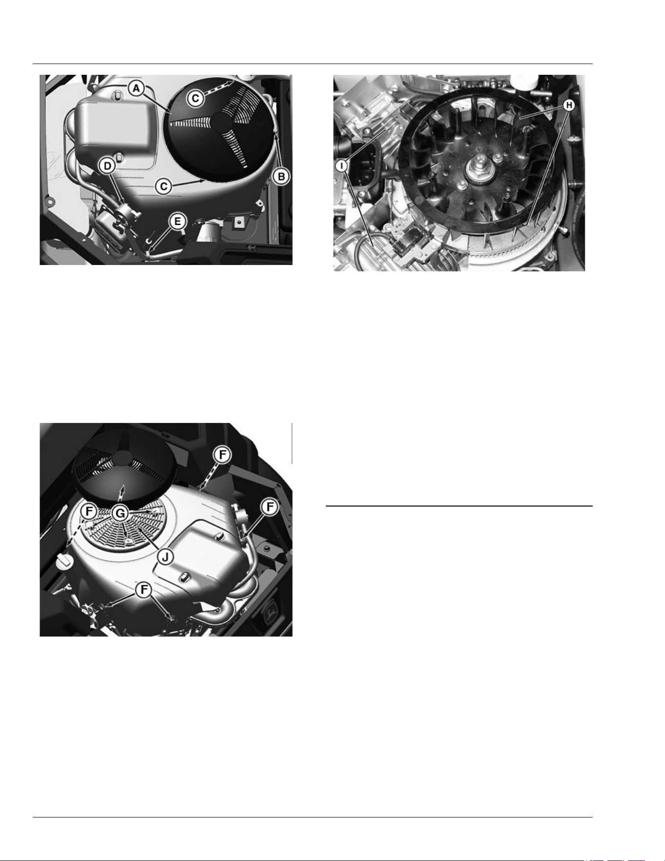
GX535575—UN—21APR22
Locate rotating screen guard (A) at the top of engine.
4. Remove screw (B) (if equipped) press in tabs (C)
and lift o guard (A).
5. Clean guard and ywheel cover of debris.
IMPORTANT: Avoid damage! Be careful to maintain
position of fuel pump assembly (D), clips (E) for
the fuel line, and any other attached
components when removing parts from the side
of engine.
APY538562—UN—13JUN22
6. Remove ve bolts (F) and engine shroud.
7. Remove four bolts (G) and rotating screen (J).
MXAL42832—UN—09APR13
8. Clean debris from:
● Fan areas (H)
● Cylinder head cooling ns (I)
● Engine cooling ns
● Area between engine and frame
9. Install rotating screen with four bolts.
IMPORTANT: Avoid damage! Engine shroud must
be assembled so that the slots in the shroud
align with the ridge in the air intake and mating
surfaces along sides of engine. Failure to
assemble correctly will prevent the air lter
from sealing and may cause engine damage.
10. Install shroud with hardware.
H9PQBYK,0000057-19-13JUN22
Checking and Cleaning Air Cleaner
Element
1. Park machine safely. (See Parking Safely in the
Safety section.)
2. Let engine cool.
IMPORTANT: Avoid damage! To prevent engine
damage, do not allow any foreign objects to fall
into the carburetor air intake.
Service Engine
45-4
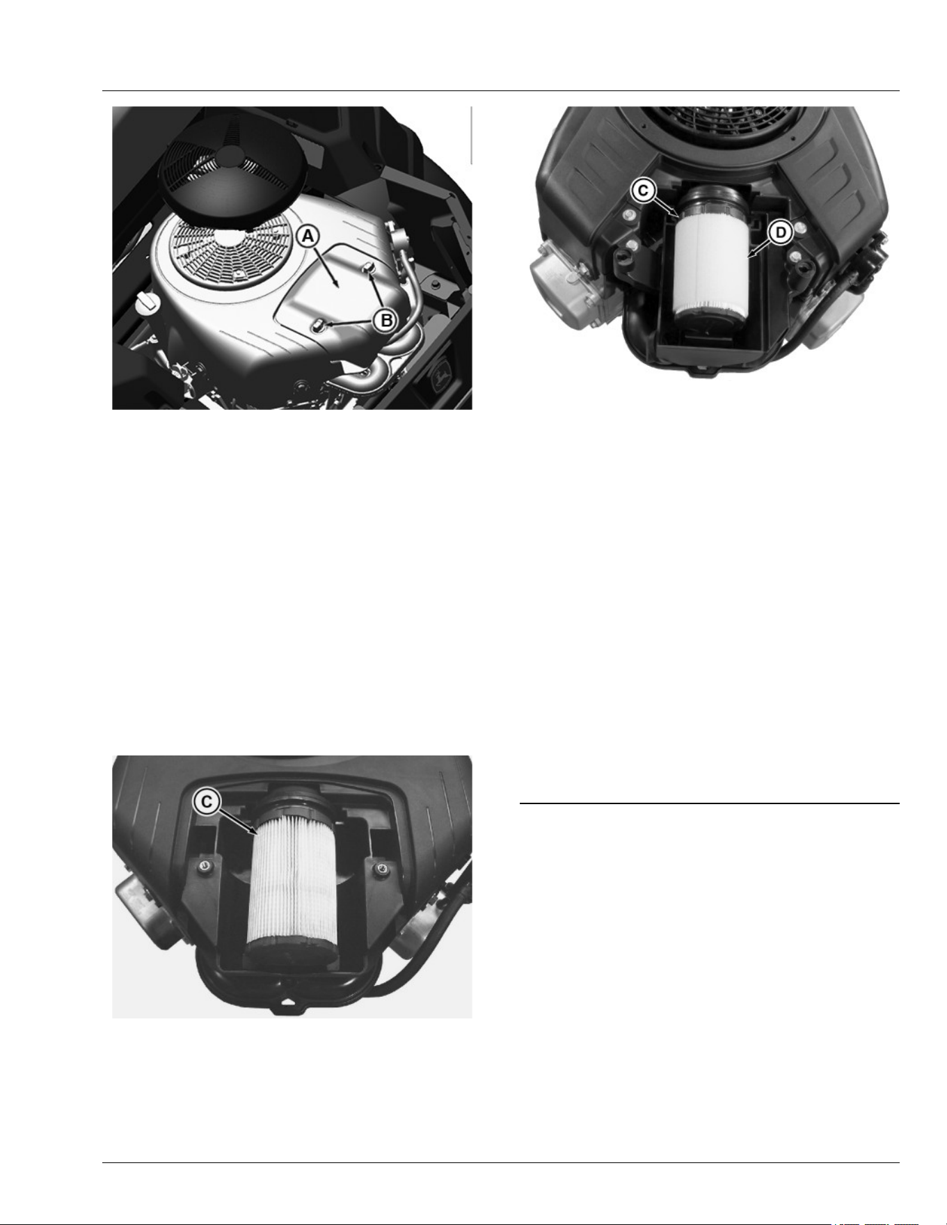
APY538563—UN—07JUN22
3. Clean dirt and debris from the air cleaner cover (A).
4. Loosen two knobs (B) and remove cover.
IMPORTANT: Avoid damage! Dirt and debris can
enter the engine through a damaged lter
element:
● Do not wash paper element.
● Do not attempt to clean paper element by
tapping against another object.
● Do not use pressurized air to clean element.
● Replace element only if it is dirty, damaged
or the seal is cracked.
NOTE: During lter cartridge removal, any material or
foreign object that enters the air intake must be
removed before replacement of the cartridge.
MXT010728—UN—21APR14
GXT002964—UN—18APR16
5. Lift out lter cartridge (C) and inspect it for damage.
NOTE: Do not put engine oil on precleaner. Engine oil
may wick into the paper lter element and result in
poor engine performance.
• Rinse precleaner thoroughly. Squeeze out excess
water in a dry cloth until precleaner is dry.
• Replace the precleaner if damaged or missing.
6. If equipped, carefully clean and inspect foam
precleaner (D).
● Wash precleaner in a solution of warm water and
liquid detergent.
7. Clean air cleaner housing carefully. Prevent any dirt
from falling into carburetor.
8. Install cartridge. Make sure that cartridge and seal
are properly seated and sealing the air intake area.
9. Install air cleaner cover and tighten knobs. Do not
overtighten.
gh8xt3t,1654597995170-19-13JUN22
Checking and Cleaning Air Cleaner
Element
1.Park machine safely. (See Parking Safely in Safety
section.)
2.Let engine cool.
IMPORTANT: Avoid damage! To prevent engine
damage, do not allow any foreign objects to fall
into the carburetor air intake.
Service Engine
45-5
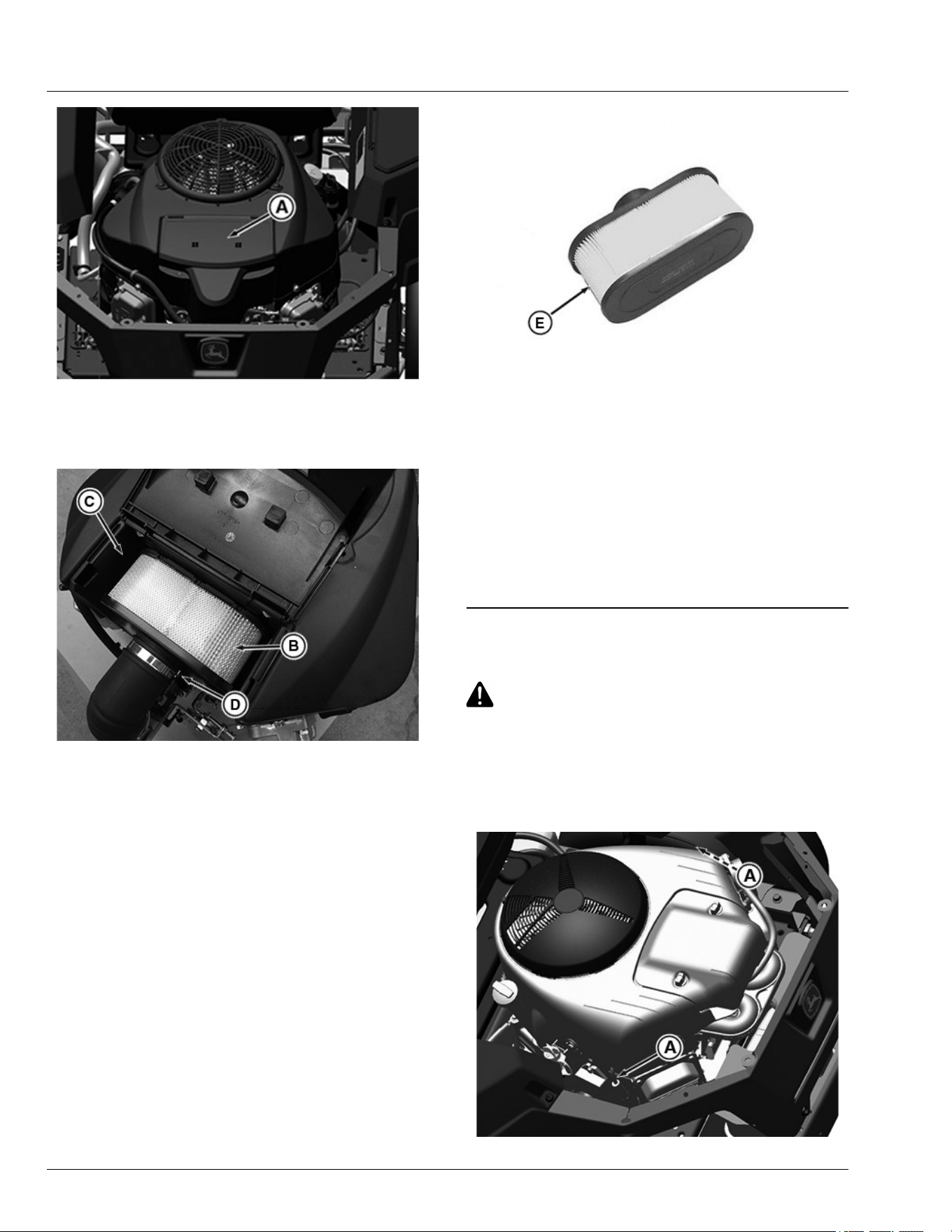
APY564724—UN—17FEB23
Engine for model Z320
3.Clean dirt and debris from the air cleaner cover and
remove the cover (A).
APY30386—UN—04MAY20
Engine for model Z320
4.Loosen air lter clamp by turning thumbscrews (D)
counterclockwise until clamp loosens. Carefully lift
the lter element (B) out of the blower housing (C)
IMPORTANT: Avoid damage! Dirt and debris can
enter the engine through a damaged lter
element
NOTE: During lter cartridge removal, any material or
foreign object that enters the air intake must be
removed before replacement of the cartridge.
APY30387—UN—04MAY20
Engine for model Z320
5.Remove the air lter (E) clean by tapping it gently on
a at surface to remove dust. If the element is very
dirty, replace it with a new one.
6.Clean air cleaner base carefully, preventing any dirt
from falling into the air intake tube.
7.Install cartridge. Make sure that cartridge and seal
are properly seated and sealing the air intake area.
8.Install air cleaner cover.
gh8xt3t,1654623265569-19-17FEB23
Checking Spark Plug
CAUTION: Avoid injury! Touching hot surfaces
can burn skin. The engine, components, and
uids are hot if the engine has been running.
Allow the engine to cool before servicing or
working near the engine and components.
1. Park machine safely (See Parking Safely in the
Safety section).
APY538564—UN—07JUN22
Service Engine
45-6
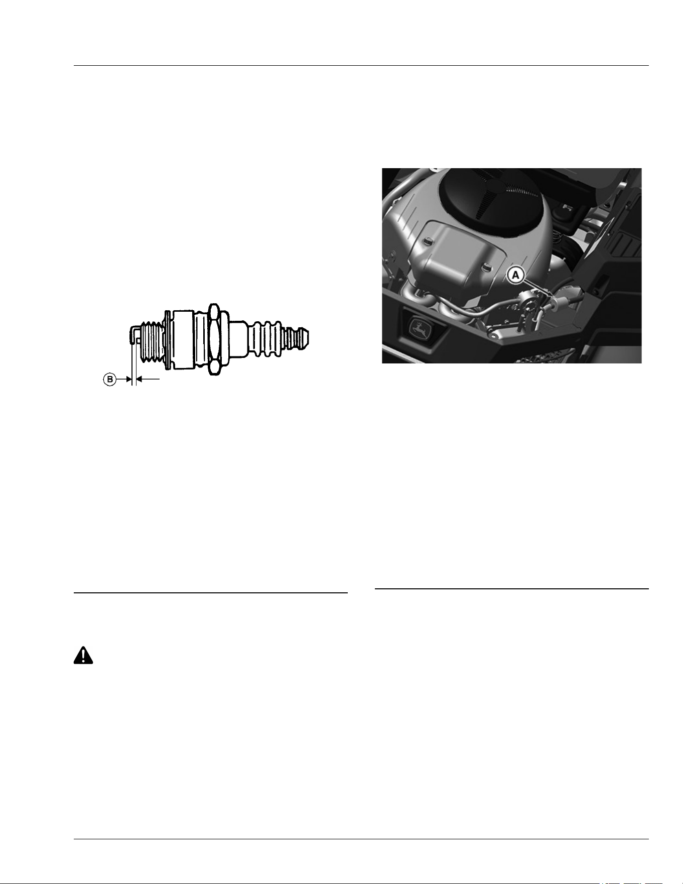
2. Disconnect spark plug wire (A) on each side of
engine.
3. Remove each spark plug.
4. Clean spark plug carefully with a wire brush.
5. Inspect the spark plug for:
● Cracked porcelain.
● Pitted or damaged electrodes.
● Other wear or damage.
NOTE: In Canada, replace the spark plug with a resistor
plug only.
6. Replace the spark plugs as necessary.
MXAL42836—UN—09APR13
7. Check plug gap (B) with a wire feeler gauge. To
change gap, move the outer electrode. Gap must be
to specication.
Specication
Electrode—Gap. . . . . . . . . . . . . . . . . . . . . . . . . 0.75 mm (0.030 in)
8. Install spark plugs and tighten to specication.
Specication
Spark Plug—Torque. . . . . . . . . . . . . . . . . . . . . . 20 N·m (180 lb·in)
9. Connect the spark plug wires.
gh8xt3t,1654598082967-19-13JUN22
Replacing Fuel Filter
CAUTION: Avoid injury! Fuel vapors are
explosive and ammable:
● Do not smoke while handling fuel.
● Keep fuel away from ames or sparks.
● Shut o engine before servicing.
● Cool engine before servicing.
● Work in a well-ventilated area.
● Clean up spilled fuel immediately.
NOTE: Change lter when fuel is low.
1. Park machine safely. (See Parking Safely in the
Safety section).
2. Let engine cool.
3. Raise operator seat if necessary.
4. Put a drain pan under the fuel lter.
GX535582—UN—21APR22
Standard twin cylinder shown.
5. Slide hose clamps on both sides of the fuel lter (A)
away from the fuel lter ends using pliers.
6. Disconnect hoses from the lter.
IMPORTANT: Avoid damage! Incorrect installation
of the fuel lter may cause engine damage.
Install the lter with the arrow pointing in the
direction of fuel ow (towards the engine) for
proper operation.
7. Connect hoses to the new lter making sure that the
lter arrow is pointing in the direction of the fuel ow.
8. Install clamps and check for leaks.
H9PQBYK,0000056-19-21APR22
Cleaning Engine Screen Guard
The twin cylinder engine incorporates a removable
guard over the rotating ywheel cover at the top of the
engine. The guard should be removed to check for and
remove any debris daily in conjunction with checking
engine oil level.
Service Engine
45-7
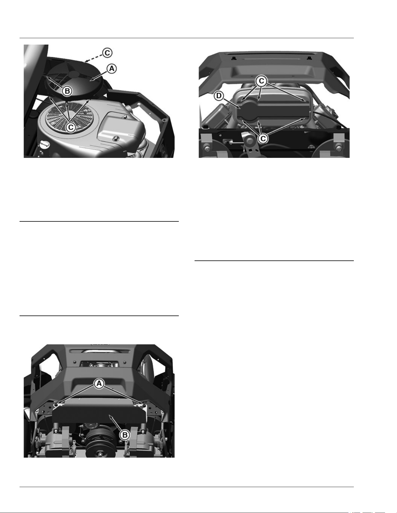
APY538565—UN—07JUN22
1. Locate rotating screen guard (A) at top of engine.
2. Remove screw (B) (if equipped), press in tabs (C)
and lift o guard (A).
3. Clean guard and ywheel cover of debris.
4. Install guard after cleaning.
gh8xt3t,1654598171387-19-07JUN22
Spark Arrestor Maintenance (If Equipped)
Spark arrestor assemblies include a screen element
that should be inspected and cleaned
periodically. Visually inspect the screen for tears, broken
wires, or loose welds. Replace the spark arrestor
assembly if any of these conditions exist. If the screen is
determined to be in good condition, proceed with
cleaning the screen by brushing away loose dirt or
carbon using a brush.
RM87422,00002DA-19-05JUL17
Cleaning Spark Arrestor
APY538835—UN—07JUN22
1. Loosen two bolts (A) and remove muer shield (B).
APY538836—UN—07JUN22
2. Remove screws (C), spark arrestor cover (D) and
spark arrestor from engine.
3. Inspect, clean, or if necessary, replace the screen if
damaged.
4. Install spark arrestor and cover on muer and secure
with original screws.
5. Install muer shield and tighten hardware.
NOTE: If muer sustains damage during the removal or
installation process, replace muer.
gh8xt3t,1654598266226-19-13JUN22
Service Engine
45-8

Checking Transmission
The transmission is a sealed component. No
maintenance is required on this transmission. If you
suspect any transmission problems, please contact your
John Deere dealer or other service provider.
TH84124,00001D2-19-17OCT25
Checking and Adjusting Neutral Creep
Checking Neutral Creep
Check neutral creep with engine running, motion control
levers in the start/shutdown position, park brake o, and
machine on level ground.
If the machine creeps forward or reverses while motion
control levers are in the start/shutdown position, adjust
the motion control lever linkages.
Adjusting Neutral Creep
1. Park machine safely. (See Parking Safely in the
Safety section.)
2. Remove style panel for better access to adjustment
components (if desired):
APY536681—UN—28APR22
a. Remove two bolts (A) to remove steering arm.
APY536682—UN—28APR22
b. Raise rear of seat and disconnect connector (B)
from the seat switch wiring harness connector.
And remove two bolts (C) to remove the seat.
APY536683—UN—28APR22
c. Remove four push retainers (D) from left side
and three push retainers (D) from right side of
the style panel (E) and remove the style panel
(E).
Service Transmission
50-1
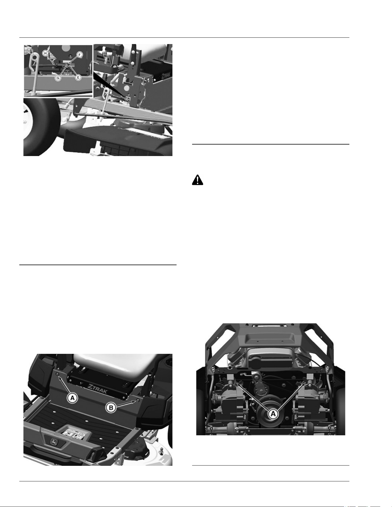
GX535583—UN—21APR22
Right Side of Machine Shown with Machine Parts Removed
for a Clearer Image
3. On linkage side needing adjustment (right side
shown), remove spring locking pin (E) and rod end
(F) from pivot pin (G). Turn rod end (F) on rod (H) in
(clockwise) to decrease forward creep and out
(counterclockwise) to decrease reverse creep.
Repeat procedure, as necessary, on opposite side.
Install rod ends back onto arms and secure with
spring locking pins.
4. Install style panel and push retainers, seat, seat
switch, and steering arm if previously removed.
GH8XT3T,00009C9-19-13JUN22
Adjusting Tracking
If the machine does not track in a straight line while
moving in full forward position, the tracking requires
adjustment.
1. Park machine safely. (See Parking Safely in the
Safety section.)
2. Use tracking adjustment socket found in the glove
box of the machine.
GX536024—UN—25APR22
3. Adjust tracking as follows:
NOTE: Tracking bolts limit top forward speed. If both
levers hit against the tracking bolts, turn both bolts
counterclockwise equally until only one bolt
contacts the lever. This will achieve maximum
forward speed.
● If machine tracks to the left, turn tracking bolt (A)
clockwise.
● If machine tracks to the right, turn tracking bolt (B)
clockwise.
H9PQBYK,0000061-19-11JUL22
Cleaning Transaxle Cooling Fans
CAUTION: Avoid injury! Compressed air can
cause debris to y a long distance.
● Clear work area of bystanders.
● Wear eye protection when using compressed
air for cleaning purposes.
● Reduce compressed air pressure to
specication.
Specication
Air—Pressure. . . . . . . . . . . . . . . . . . . . . . .. . . . . 210 kPa (30 psi)
IMPORTANT: To ensure proper cooling, keep the
transaxle cooling ns and surrounding area
clean at all times. Operating the transaxle with
obstructed cooling ns could cause damage
due to overheating.
1. Park machine safely. (See Parking Safely in the
Safety section.)
APY74525—UN—09JUN22
2. Clean transaxle fan ns (A) and around exterior of
each fan with a rag, brush or compressed air.
gh8xt3t,1654601475909-19-07JUN22
Service Transmission
50-2
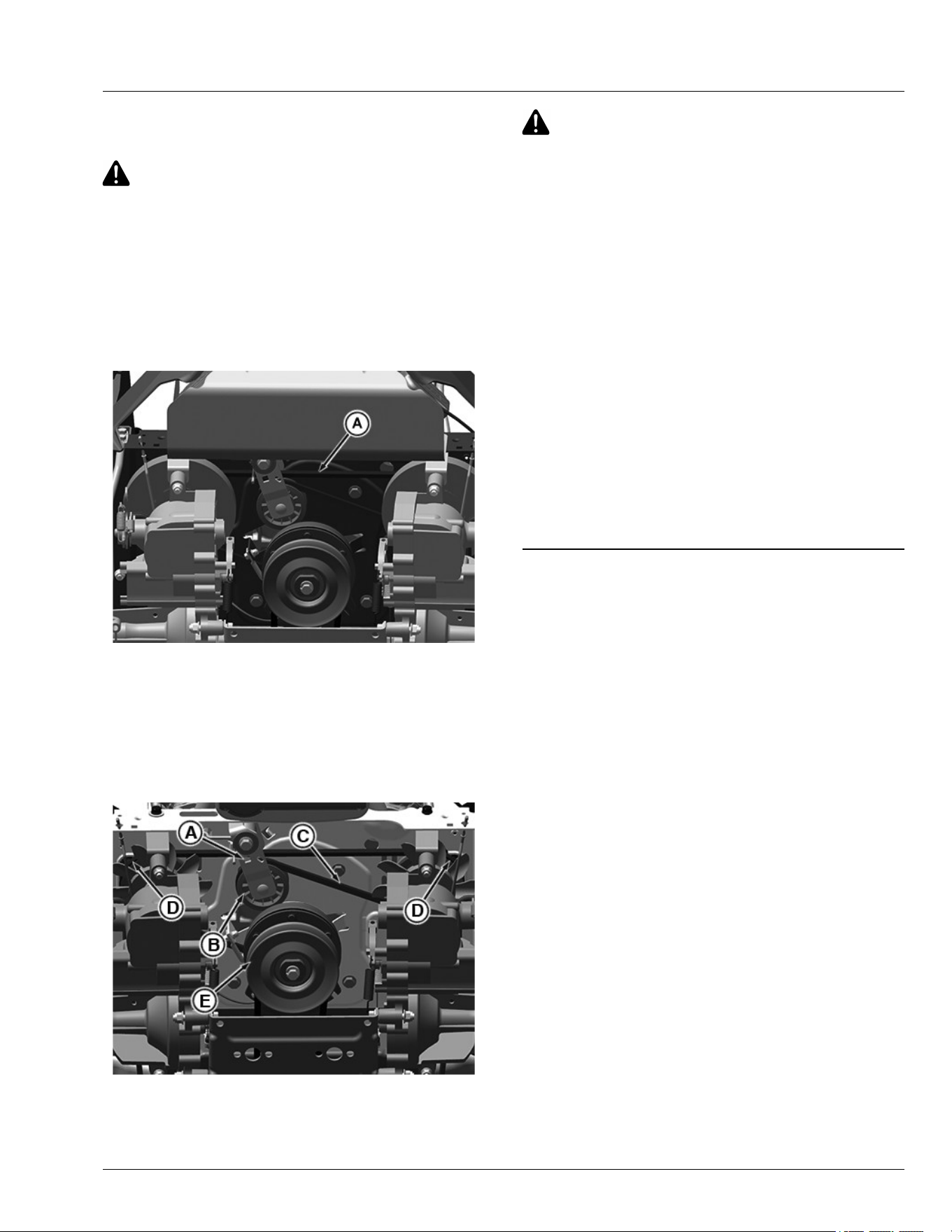
Checking and Replacing Transaxle/
Transmission Drive Belt
CAUTION: Avoid injury! Entanglement in a belt
or sheave can cause serious injury. Stop engine
and wait for all moving parts to stop.
NOTE: The transmission drive belts are self-adjusted
using a spring tensioner and do not require a
tension adjustment.
Checking Transaxle/Transmission Drive Belts
1. Park machine safely. (See Parking Safely in the
Safety section.)
APY74526—UN—09JUN22
2. Inspect drive belt (A) for excessive wear, damage or
stretching while in position on all machine sheaves.
Replacing Transaxle/Transmission Drive Belts
1. Park machine safely. (See Parking Safely in the
Safety section.)
2. Remove mower deck.
APY74527—UN—07JUN22
Components viewed from bottom.
3. Disconnect electric clutch wiring connector from
main wiring harness connector.
CAUTION: Avoid injury! Components are
installed under spring tension. Wear eye
protection and use proper tools when installing
and removing components with spring tension.
4. Insert a 3/8 in. ratchet or breaker bar into the square
hole (A) on the idler arm, rotate the spring-loaded
idler arm to relieve belt tension on the idler sheave
(B) and remove the drive belt (C) from the idler
sheave. Release the spring tension from the arm
and remove the tool.
5. Remove the drive belt from both transaxle sheaves
(D).
6. Remove the drive belt from the engine sheave (E).
7. Position replacement belt onto engine sheave (E),
and both transaxle sheaves (D).
8. Rotate the spring-loaded idler arm (A) and install
the belt on the idler sheave (B).
9. Connect electric clutch wiring harness connector (A)
to main wiring harness.
10. Install mower deck.
gh8xt3t,1654601593685-19-13JUN22
Service Transmission
50-3
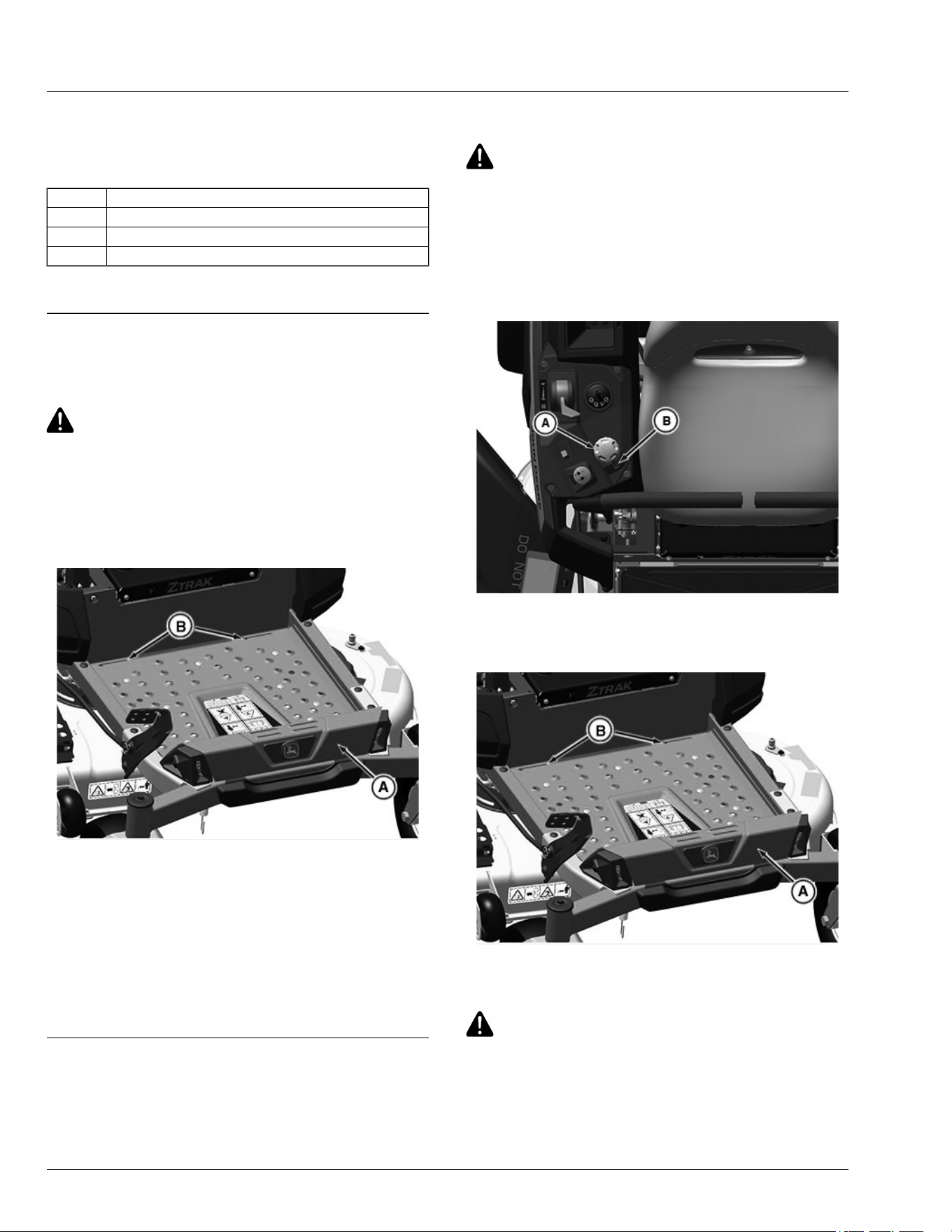
Mower Deck Identication
Mower decks in the following instructions are identied
by a code designation. The codes are as follows:
Code Description
42A 42 inch Accel Deep™
48A 48 inch Accel Deep™
54A 54 inch Accel Deep™
Accel Deep is a trademark of Deere & Company
MX52301,0000F0A-19-28MAR16
Removing and Installing Mower Deck Foot
Plate
CAUTION: Avoid injury! Always operate the
mower with the foot plate installed. Operating
with the foot plate removed can cause serious
injury.
Removing Foot Plate
1. Park machine safely. (See Parking Safely in the
Safety section.)
GX536025—UN—25APR22
2. Lift the front end of the foot plate (A).
3. Using both hands, pull the foot plate out of the two
openings (B) in the frame.
Installing Foot Plate
1. Using both hands, position the foot plate (A) into the
two openings (B) in the frame.
2. Lower the foot plate until it rests securely in place.
H9PQBYK,0000051-19-25APR22
Removing Mower Deck (42A)
1. Park machine safely. (see parking safely in the safety
section.)
2. Allow engine and muer to cool completely.
CAUTION: Avoid injury! Rotating blades are
dangerous.
Before adjusting or servicing mower:
● Disconnect spark plug wires or battery
negative (-) cable to prevent engine from
starting accidentally.
● Always wear gloves when handling mower
blades or working near blades.
APY69519—UN—08MAR22
3. Rotate the height-of-cut dial (A) in clockwise direction
to the lowest range in index mark (B) to lower deck to
1.25" height-of-cut for lockout position.
GX536026—UN—25APR22
4. Lift the front end of the foot plate (A) and remove the
foot plate from the slots (B).
CAUTION: Avoid injury! Component is spring-
assisted and under tension. Injury can occur if
spring-assisted component is released
suddenly.
5. Disconnect mower drive belt:
Service Mower
55-1
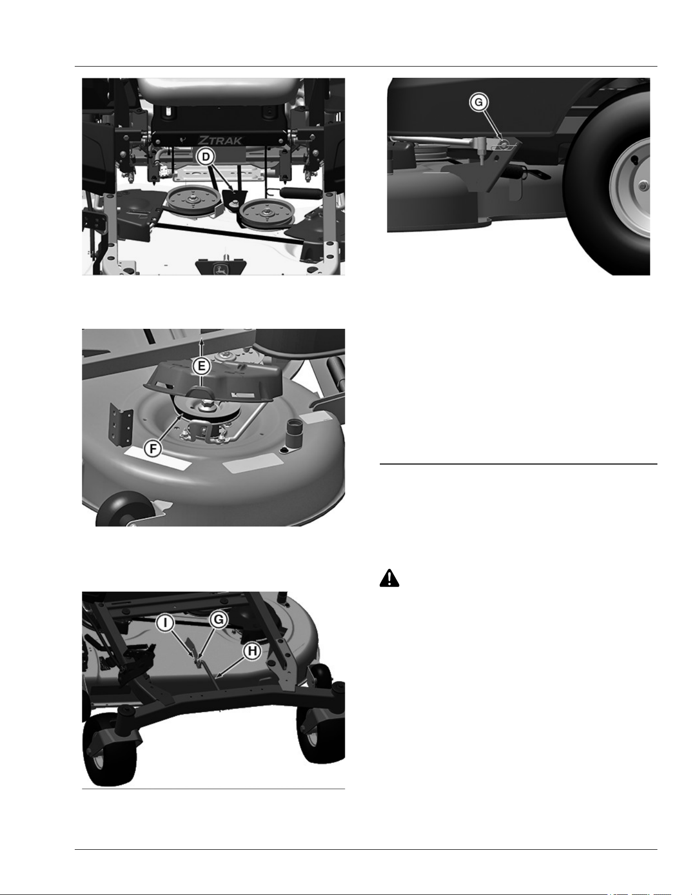
APY74528—UN—07JUN22
● Install 3/8 inch ratchet onto square hole (D)
tension arm and rotate counterclockwise to
release tension on the belt.
PY43366—UN—30MAY17
● Lift spindle cover (E) while removing mower belt
(F) from left spindle sheave.
● Remove belt from the engine sheave.
APY69553—UN—18MAR22
6. Remove locking pin and washer (G) and front lift arm
(H) from the front deck bracket (I).
APY04442—UN—18JUL18
42A Mower Deck Left Side Shown
7. Remove spring pin (G) and pin from each side of the
rear mower bracket.
8. Rotate front caster wheels to maximize clearance.
9. Slide mower out from under the machine.
● Do not operate the machine without the mower
deck: Machine may become unstable without the
mower deck attached. Move machine only by
hand. (See Moving Machine by Hand in Operating
section.)
GH8XT3T,00008D9-19-07JUN22
Removing Mower Deck (48A and 54A)
1. Park machine safely. (See Parking Safely in the
Safety Section.)
2. Allow the engine and muer to cool completely.
CAUTION: Avoid injury! Rotating blades are
dangerous. Before adjusting or servicing
mower:
• Disconnect spark plug wires or battery
negative (-) cable to prevent engine from
starting accidentally.
• Always wear gloves when handling mower
blades or working near blades.
Service Mower
55-2
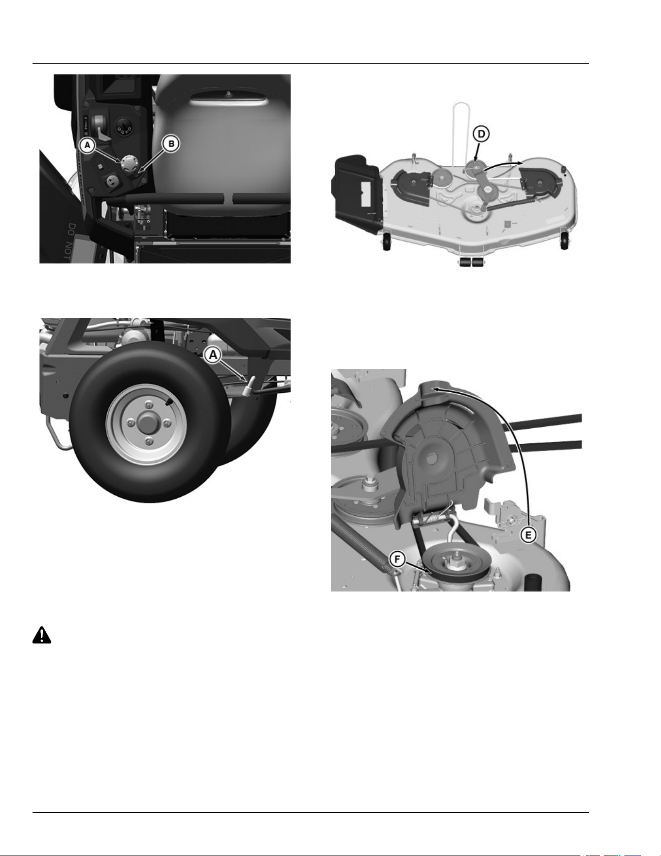
APY69519—UN—08MAR22
3. Rotate the height-of-cut dial (A) in clockwise
direction to the lowest position (1.25") in the index
mark (B) to lock position.
APY540989—UN—05JUL22
4. Use the tracking adjustment socket (A) found in the
glove box to lock the lift system when removing the
deck.
NOTE: Use of the tracking adjustment socket restrains
the lift spring from rotating the rockshaft.
5. Disconnect mower drive belt:
CAUTION: Avoid injury! Component is spring-
assisted and under tension. Injury can occur if
spring-assisted component is released
suddenly.
GXT002904—UN—10JUN16
Deck Shown Removed from Machine for Better View
● From the left side of machine, insert a 3/8 inch
ratchet into square hole (D) in the tension arm,
and pull clockwise and hold to release tension on
belt.
GXT003023—UN—10JUN16
Deck Shown Removed from Machine for Better View.
● Raise left spindle cover (E) and remove belt (F)
from spindle.
● Remove belt from clutch sheave.
Service Mower
55-3
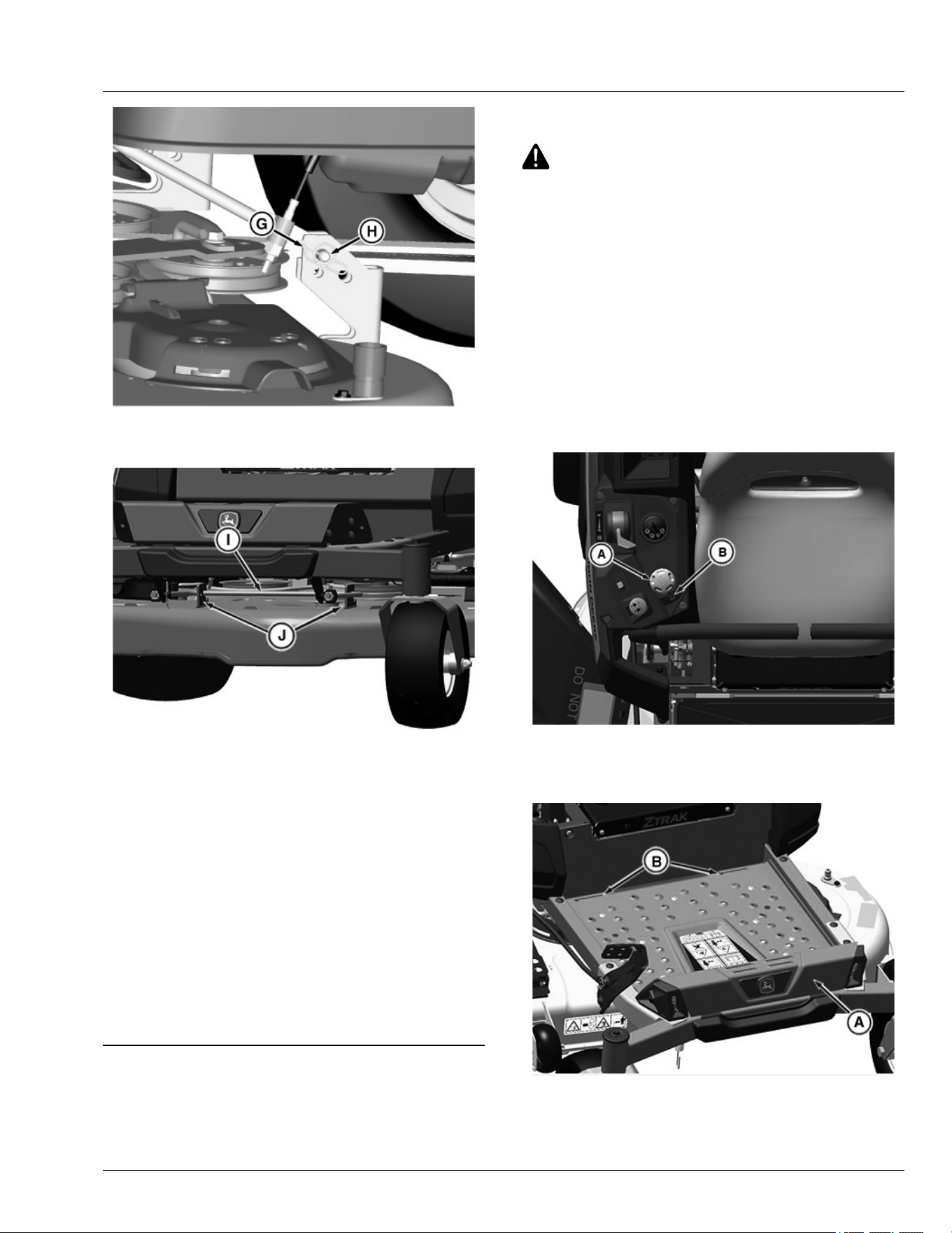
GXT003022—UN—10JUN16
6. Remove spring pin (G) and pin (H) from each side of
the rear hanger bracket.
APY536726—UN—09MAY22
7. 48A and 54A Mower Decks Only: Move mower
deck forward to remove front draft link (I) from the
mower deck brackets (J).
8. Rotate the height-of-cut dial (A) in counterclockwise
direction to the highest range in the index mark (B)
to lock deck in raise position.
9. Rotate front caster wheels to maximize clearance.
10. Slide mower out from under the machine.
● Do not operate the machine without the mower
deck, Machine may become unstable without the
mower deck attached. Move machine only by
hand. (see moving machine by hand in operating
section.)
GH8XT3T,00008DA-19-08JUL22
Installing Mower Deck (42A)
1. Park machine safely. (See Parking Safely in the
Safety section.)
2. Allow engine and muer to cool completely.
CAUTION: Avoid injury! Rotating blades are
dangerous.
Before adjusting or servicing mower:
● Disconnect spark plug wires or battery
negative (-) cable to prevent engine from
starting accidentally.
● Always wear gloves when handling mower
blades or working near blades.
3. Rotated the height-of-cut dial counterclockwise
direction to lock in raise position.
4. Remove belt from the mower right-hand spindle
sheave to allow more slack for installation of the belt
onto clutch.
5. Slide mower deck under machine.
APY69519—UN—08MAR22
6. Rotate the height-of-cut dial (A) clockwise direction
to the lowest range in index mark (B) to lock deck in
lowered position.
GX536025—UN—25APR22
7. Lift the front end of the foot plate (A) and remove the
foot plate from the slots (B).
Service Mower
55-4
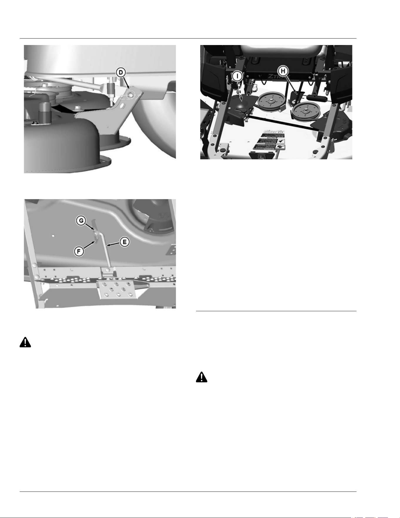
GXT001925—UN—17JUL15
8. Install pin and spring pin (D) onto each side of the
rear mower bracket.
GXT001926—UN—17JUL15
9. Install front lift arm (E) onto the front deck bracket
(G) and secure with washer and locking pin (F).
CAUTION: Avoid injury! Component is spring-
assisted and under tension. Injury can occur if
spring-assisted component is released
suddenly.
APY74529—UN—07JUN22
10. Connect mower drive belt:
● Install belt onto the engine sheave.
IMPORTANT: Avoid damage! Left and right
spindle sheaves are hidden by belt shields.
Failure to position the belt properly on
sheaves may result in belt damage.
● Install 3/8 inch ratchet onto the square hole (H) in
the tension arm and rotate counterclockwise to
release tension on the belt. Lift right spindle
cover and install belt onto right spindle sheave
(I). Make sure that belt is properly seated on all
sheaves.
11. Flip up left and right spindle covers to verify that belt
is properly seated in both spindle sheaves.
12. Install foot plate.
GH8XT3T,00008DB-19-13JUN22
Installing Mower Deck (48A and 54A)
1. Park machine safely. (See Parking Safely in the
Safety Section.)
2. Allow engine and muer to cool completely.
CAUTION: Avoid injury! Rotating blades are
dangerous. Before adjusting or servicing
mower:
• Disconnect spark plug wires or battery
negative (-) cable to prevent engine from
starting accidentally.
• Always wear gloves when handling mower
blades or working near blades.
Service Mower
55-5
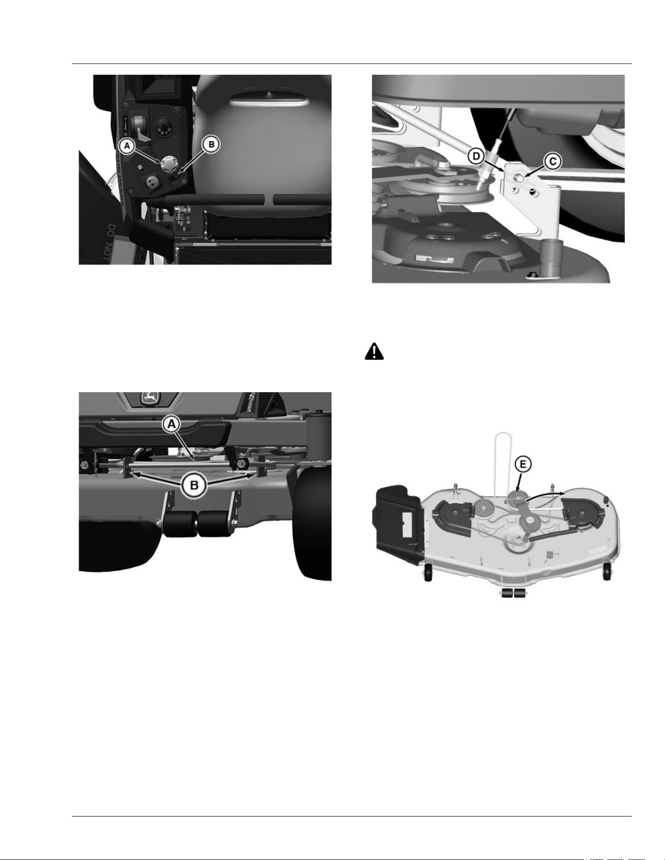
APY69519—UN—08MAR22
3. Rotate the height-of-cut dial (A) counterclockwise
direction to the highest range in index mark (B) to
raise mower deck.
NOTE: Ensure to remove the tracking adjustment
socket used for lift system before installation of
mower deck.
4. Slide mower deck under machine.
APY69550—UN—07MAR22
5. Move mower deck forward and lower front draft rod
(A) into the front mower deck brackets (B).
GXT003024—UN—10JUN16
6. Lower mower lift lever, and install the pin (C) and
spring pin (D) onto each side of the rear mower
bracket.
CAUTION: Avoid injury! Component is spring-
assisted and under tension. Injury can occur if
spring-assisted component is released
suddenly.
GXT003026—UN—10JUN16
48A shown
7. Connect mower drive belt:
● Install belt onto the engine sheave.
IMPORTANT: Avoid damage! Left and right
spindle sheaves are hidden by belt shields.
Failure to position the belt properly on
sheaves may result in belt damage.
● Insert 3/8 inch ratchet onto the square hole (E) in
the tension arm. Rotate arm clockwise and hold to
release spring tension on idler sheave.
Service Mower
55-6
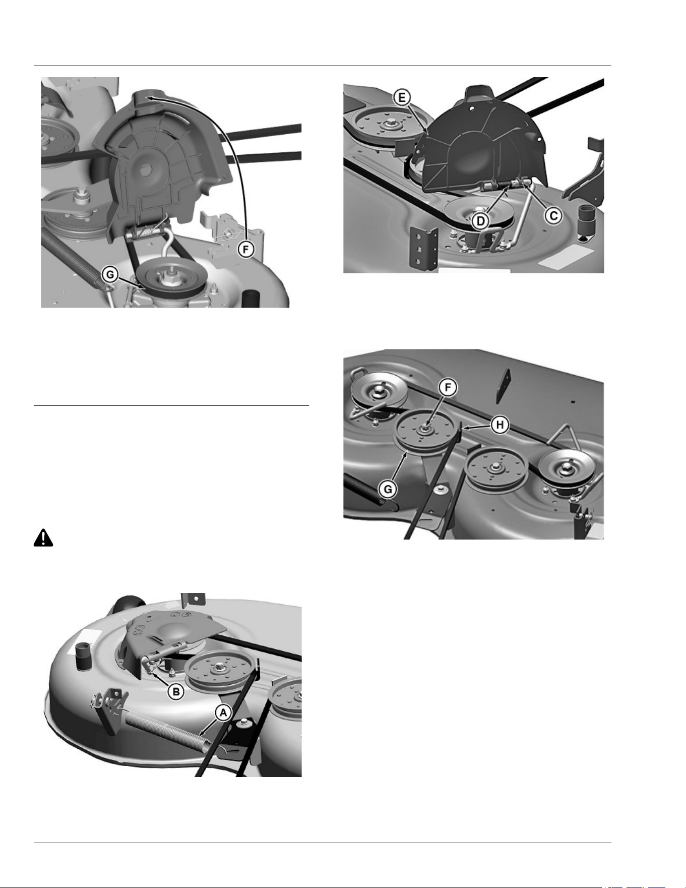
GXT003027—UN—10JUN16
● Lift left spindle cover (F) and install mower belt (G)
onto left spindle sheave. Release spindle cover
and tension arm.
● Flip up left and right spindle covers to check that
belt is correctly routed on all sheaves.
GH8XT3T,00008DC-19-08JUL22
Replacing Mower Drive Belt (42A Mower)
1. Park machine safely. (See Parking Safely in Safety
section.)
2. Allow engine and muer to cool completely.
3. Remove mower deck.
CAUTION: Avoid injury! Components are
installed under spring tension. Wear eye
protection and use proper tools when installing
and removing components with spring tension.
GXT002326—UN—06JUL15
4. Remove spring (A) from tension arm.
PY43369—UN—02JUN17
5. Lift left spindle cover. Align keyway in shield (C) with
stake in wire form (D) and slide spindle cover (E) o
wire form.
6. Repeat step 4 and 5 to remove right spindle cover.
MX101512—UN—02JUN20
7. Remove nut (F) on tension arm and lift sheave (G)
up to remove belt from guide (H).
8. Remove belt from deck and inspect for wear or
damage; replace as necessary.
9. Clean top surface of mower deck and sheaves.
10. Install belt on mower deck as shown.
Service Mower
55-7
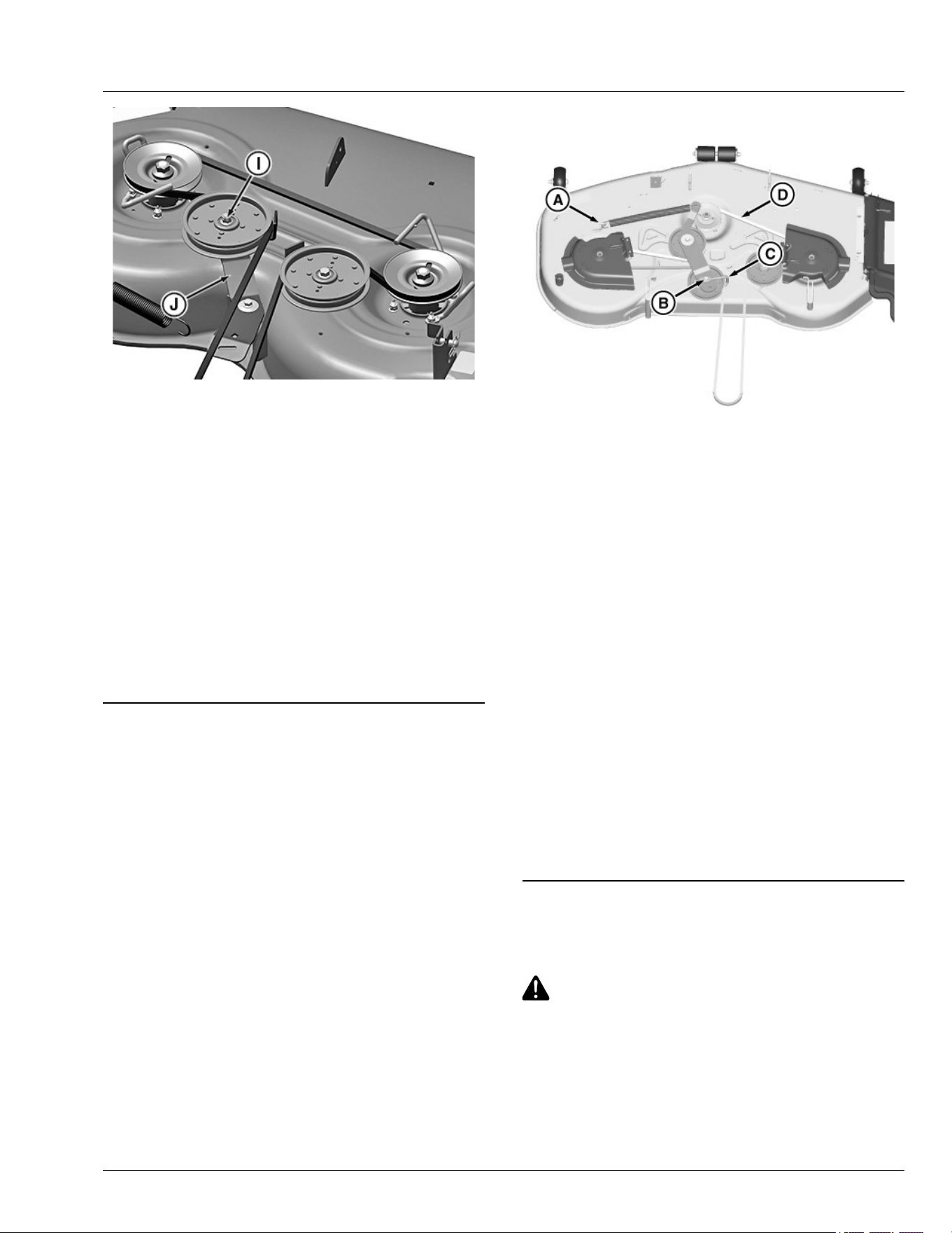
PY43371—UN—30MAY17
Shown without sheave for clarity only.
11. Make sure sheave carriage bolt (I) is fully seated
into tension arm (J). Install sheave with belt on
tension arm.
12. Tighten sheave hardware to specication.
Specication
Sheave—Torque. . . . . . . . . . . . . . . . . . . . . . . . . . 47 N·m (35 lb·ft)
13. Make sure that belt is properly seated on all
sheaves.
14. Install left and right spindle covers on wire forms.
15. Install spring on tension arm.
16. Install mower deck.
RM87422,0000747-19-02JUN20
Replacing Mower Drive Belt (48A and 54A
Mower Decks)
1. Park machine safely. (See Parking Safely in Safety
section.)
2. Allow engine and muer to cool completely.
3. Remove mower deck.
4. Remove deck drive belt as follows:
GXT002905—UN—10JUN16
● Remove spring from welded spring hook (A) on
deck.
● Remove nut (B) on the tension sheave and lower
bolt to remove guide (C). Remove belt (D) from
all sheaves.
5. Inspect belt for wear or damage; replace as
necessary.
6. Clean top surface of the mower deck and sheaves.
IMPORTANT: Avoid damage! Left and right spindle
sheaves are hidden by belt shields. Failure to
position the belt properly on sheaves may
result in belt damage.
7. Install belt on the mower deck as shown.
8. Make sure belt guide (C) is indexed as shown and
tighten nut (B) to specication.
Specication
Sheave Nut—Torque. . . . . . . . . . . . . . . . . . . . . . . 47 N·m (35 lb·ft)
9. Install spring on welded spring hook (A) on deck.
10. Install mower deck.
MX52301,0000F07-19-01JUN20
Installing MulchControl Discharge Plate (If
Equipped)
CAUTION: Avoid injury! Machine component or
attachment is heavy. Use a safe lifting device or
get an assistant to help lift, install, or remove
component or attachment.
NOTE: For ease of installation, place mower deck in the
vertical position.
Service Mower
55-8
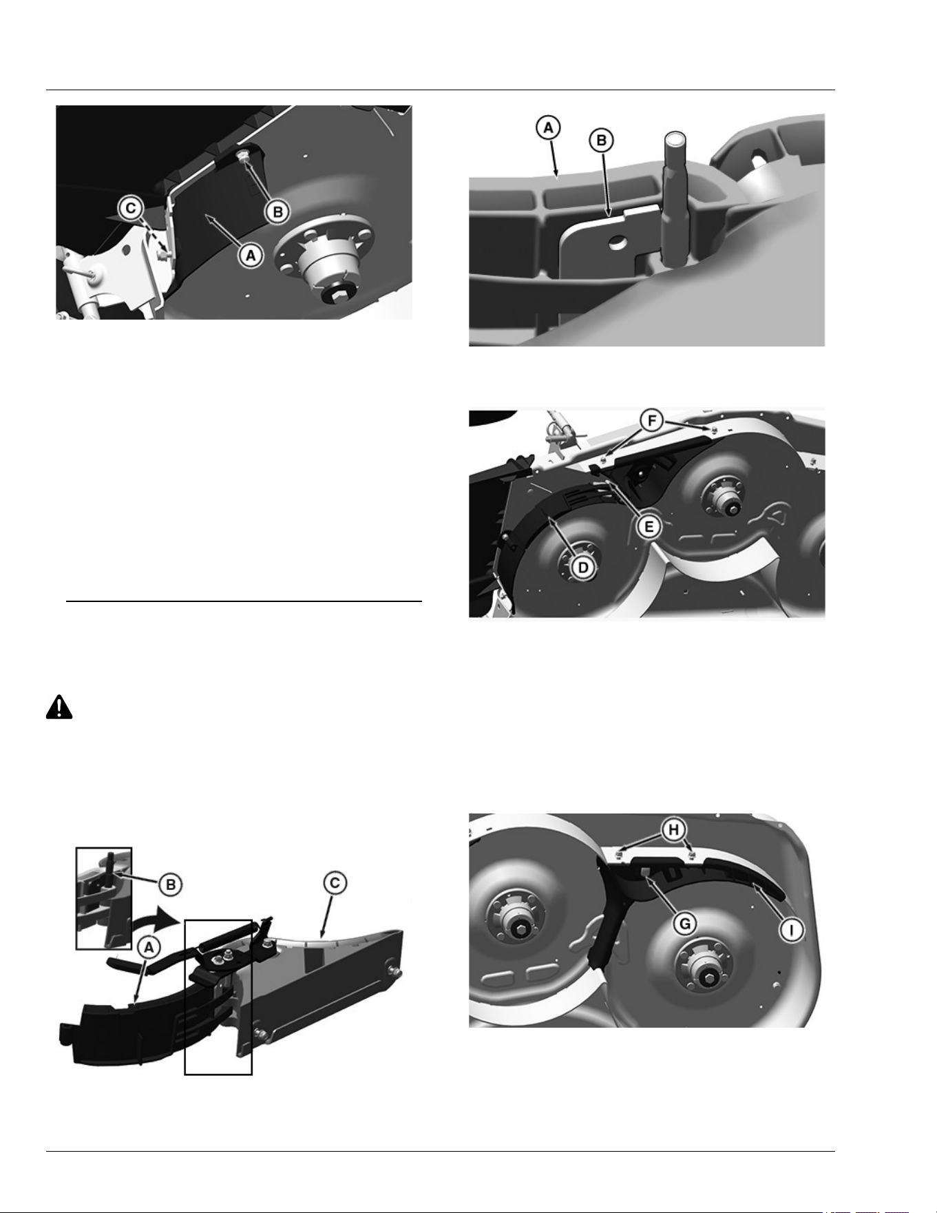
APY24927—UN—13JAN20
1. Position discharge plate (A) as shown.
2. Insert M8 x 20 carriage bolt (B) through the mower
deck and into the hole in the discharge plate.
3. Install M8 lock nut on bolt (B). Do not tighten yet.
4. Insert M8 shoulder bolt (C) through the discharge
plate and into the hole in the mower deck.
5. Install M8 lock nut on bolt (C).
6. Tighten nuts.
Specication
M8 Nut—Torque. . . . . . . . . . . . . . . . . . . . . . . . . . . . . . . . . 20 N·m
(15 lb·ft)
SB31882,00003E0-19-02JUN20
Installing MulchControl Deector (If
Equipped)
CAUTION: Avoid injury! Machine component or
attachment is heavy. Use a safe lifting device or
get an assistant to help lift, install, or remove
component or attachment.
NOTE: For ease of installation, place mower deck in the
vertical position.
APY24928—UN—26MAY20
MX101515—UN—03JUN20
1. Assemble kit gate (A) and bae (C) together as
shown and insert the pin (B) in the slots.
APY24929—UN—11DEC19
2. Install right deector assembly (D) to the mower deck
using M8 shoulder bolts (F) and M8 nuts.
3. Ensure the pin (E) is in the correct slot and that the
gate door can open and close.
4. Tighten lock nuts.
Specication
M8 Lock Nut—Torque. . . . . . . . . . . . . . . . . . . . . . . . . . . . . 20 N·m
(15 lb·ft)
APY24930—UN—13DEC19
5. Install left deector assembly (I) to the mower deck
as shown using M8 shoulder bolts (H) and M8 nuts.
6. On the top side of deck, install M8 lock nut on
shoulder bolt (G).
Service Mower
55-9
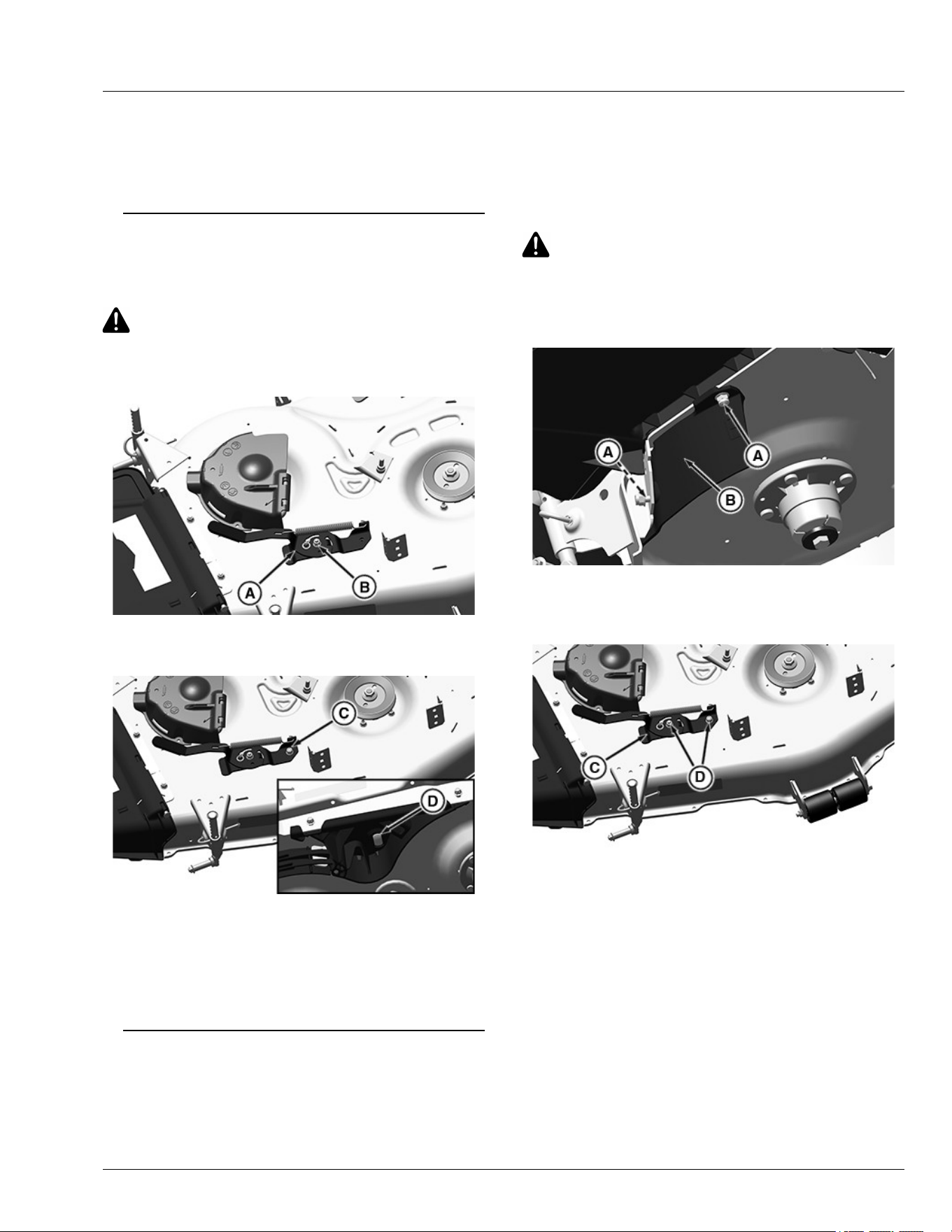
7. Tighten lock nuts.
Specication
M8 Lock Nut—Torque. . . . . . . . . . . . . . . . . . . . . . . . . . . . . 20 N·m
(15 lb·ft)
SB31882,00003E1-19-03JUN20
Installing MulchControl Handle (If
Equipped)
CAUTION: Avoid injury! Machine component or
attachment is heavy. Use a safe lifting device or
get an assistant to help lift, install, or remove
component or attachment.
APY24932—UN—11DEC19
1. Install handle assembly (A) to hinge pin with a M8
lock nut (B). Tighten lock nut until snug on handle.
APY24931—UN—11DEC19
2. On the top side of deck, install M8 lock nut (C) on the
shoulder bolt (D) to secure handle assembly.
Specication
M8 Nut—Torque. . . . . . . . . . . . . . . . . . . . . . . . . . . . . . . . . 20 N·m
(15 lb·ft)
SB31882,00003E2-19-02JUN20
Removing and Storing MulchControl Deck
(If Equipped)
Removing MulchControl™
1. Remove the mower deck. (See Removing Mower
Deck in this section of the manual.)
CAUTION: Avoid injury! Blades are sharp.
Always wear gloves when handling blades or
working near blades. Replace blades if
defective. Never straighten or weld them.
2. Remove mulch blades.
APY24982—UN—16DEC19
3. Remove discharge plate (B) from discharge area by
removing the hex ange bolts (A) and hex ange
nuts.
APY24977—UN—16DEC19
4. Loosen nuts (D) and remove the handle assembly
(C).
MulchControl is a trademark of Deere & Company
Service Mower
55-10
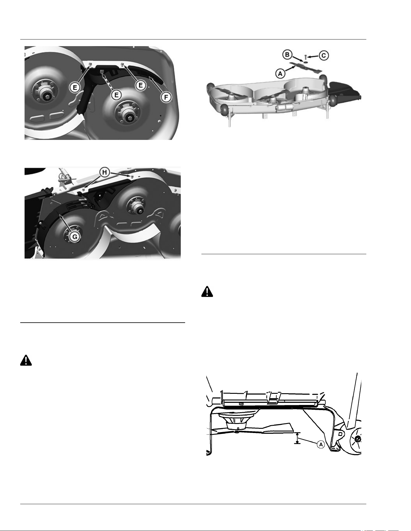
APY24979—UN—16DEC19
5. Loosen hex nuts (E) and remove M8 bolts and then
remove the LHS deector assembly (F).
APY24980—UN—16DEC19
6. Loosen hex nuts (H) and remove M8 bolts and then
remove the RHS deector assembly (G).
Storing MulchControl™
Clean and store all MulchControl™ parts in a clean, dry
place.
SB31882,00003E5-19-10JUN20
Installing Mulch Blades
CAUTION: Avoid injury! Blades are sharp.
Always wear gloves when handling blades or
working near blades. Replace blades if
defective. Never straighten or weld them.
MXT015291—UN—19AUG15
1. Install blade (A) with cutting edge toward the ground.
2. Install large washer (B) and bolt (C).
3. Insert wood block between blade and mower to
prevent the blade from turning when tightening bolt.
4. Tighten bolt.
Specication
Blade Bolt—Torque. . . . . . . . . . . . . . . . . . . . . . . . . . . . . . . 68 N·m
(50 lb·ft)
5. To check blade-to-mulch bae clearance, rotate
blades by hand. If interference occurs, check that
hardware is tightened.
SB31882,00003E3-19-27MAY20
Checking for Bent Mower Blades
CAUTION: Avoid Injury! Blades are sharp.
Always wear gloves when handling blades or
working near blades.
Replace blades if defective. Never straighten or
weld them.
1. Park machine safely. (See Parking Safely in the
Safety section.)
2. Raise mower deck to highest position to access
blades.
MXAL42867—UN—09APR13
Mower deck with side discharge used for illustration
MulchControl is a trademark of Deere & Company
Service Mower
55-11
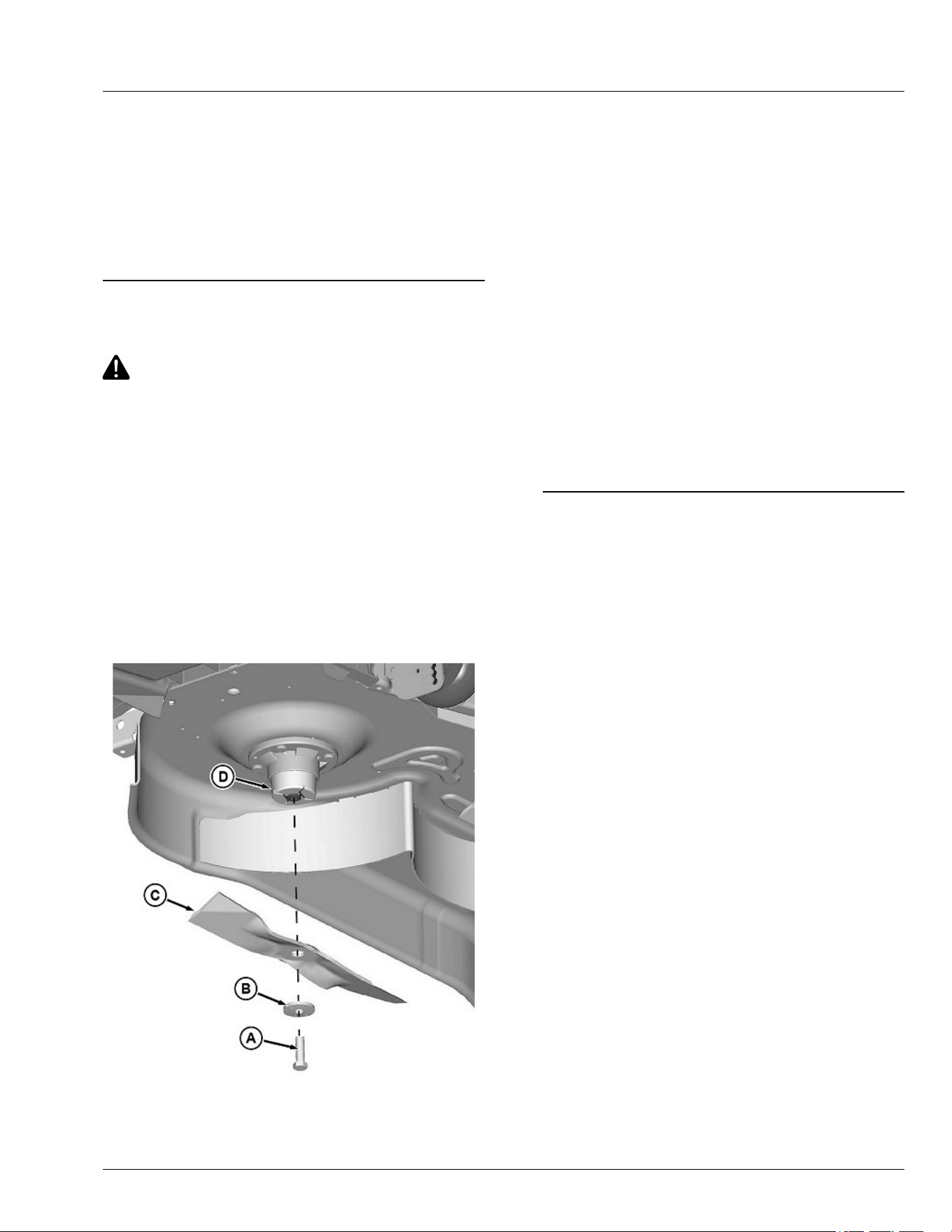
3. Measure distance (A) between blade tip and at
ground surface.
4. Rotate blade 180° and measure distance between
other blade tip and at ground surface.
5. Install new blade if the dierence between the two
measurements is more than 3 mm (1/8 in).
6. Repeat for all blades.
MP47322,00F466C-19-12JAN23
Servicing Mower Blades
CAUTION: Avoid injury! Rotating blades are
dangerous.
Before adjusting or servicing mower:
● Disconnect spark plug wire(s) or battery
negative (-) cable to prevent engine from
starting accidentally.
● Always wear gloves when handling mower
blades or working near blades.
Removing Mower Blades (42A, 48A, and 54A Mower
Decks)
1. Park machine safely. (See Parking Safely in the
SAFETY section.)
2. Raise mower deck to gain access to mower blades. If
necessary, remove mower deck.
GXT001605—UN—13MAY15
3. Block mower blade with a piece of wood to prevent it
from spinning.
4. Loosen and remove bolt (A), washer (B), and blade
(C) from spindle (D).
5. Inspect blades; sharpen, balance or replace blades
as necessary.
Installing Mower Blades (42A, 48A, and 54A Mower
Decks)
1. Make sure deector cup (D) is seated properly
between mower spindle and blade.
2. Position mower blade (C) with cutting edge toward
ground onto mower spindle.
3. Install washer (B), with cupped side towards blade,
and bolt (A) to secure blade onto spindle shaft.
4. Block mower blade with a piece of wood to prevent
spinning and tighten bolt to specication.
Specication
Mower Blade Bolt—Torque. . . . . . . . . . . . . . . . . . . . . . . . . 68 N·m
(50 lb·ft)
gh8xt3t,1693805318209-19-04SEP23
Service Mower
55-12
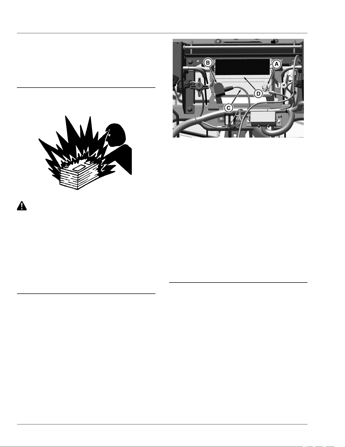
Electrical
WARNING: Avoid injury! Battery posts, terminals and
related accessories contain lead and lead components,
chemicals known to the State of California to cause
cancer and reproductive harm. Wash hands after
handling.
MP47322,00F466E-19-04AUG25
Service the Battery Safely
MXAL42869—UN—09APR13
CAUTION: Avoid injury! The battery produces a
ammable and explosive gas.
To prevent the battery from exploding:
● Do not smoke or have open ame near
battery.
● Wear eye protection and gloves.
● Do not allow direct metal contact across
battery posts.
● Remove negative cable rst when
disconnecting.
● Install negative cable last when connecting.
MP47322,00F466F-19-13JAN15
Removing and Installing the Battery
Removing
1. Park machine safely. (See Parking Safely in the
Safety section.)
2. Rotate operator seat forward.
3. Remove battery compartment cover.
GX536017—UN—26APR22
4. Disconnect negative (-) battery cable (A).
5. Push red cover (B) away from positive (+) battery
terminal and remove cable (C) from battery.
6. Remove strap (D).
7. Remove battery.
Installing
1. Place battery into the battery tray as shown.
2. Put battery strap.
3. Connect positive (+) cable to battery rst, then
negative (-) cable.
4. Apply general-purpose grease or silicone spray to
terminals to help prevent corrosion.
5. Slide red cover over the positive battery terminal.
6. Install battery compartment cover.
7. Lower operator seat.
H9PQBYK,0000050-19-21APR22
Cleaning Battery and Terminals
1. Park machine safely. (See Parking Safely in the
Safety section.)
2. Disconnect and remove battery.
3. Wash battery with solution of four tablespoons of
baking soda to one gallon of water. Be careful not to
get the soda solution into the cells.
4. Rinse the battery with plain water and dry.
5. Clean terminals and battery cable ends with wire
brush until bright.
6. Install battery.
7. Attach cables to battery terminals, beginning with the
positive cable, using washers and nuts.
Service Electrical
60-1
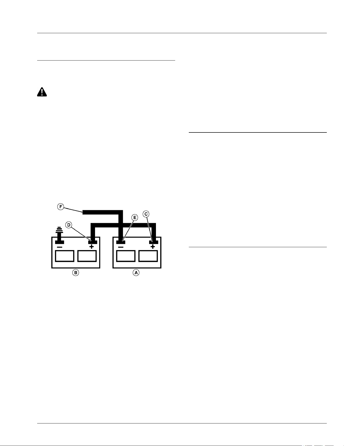
8. Apply general purpose grease or silicone spray to
terminals to help prevent corrosion.
MG39705,00000D8-19-13JUN22
Use Booster Battery
CAUTION: Avoid injury! The battery produces a
ammable and explosive gas.
To prevent the battery from exploding:
● Do not smoke or have open ame near
battery.
● Wear eye protection and gloves.
● Do not jump-start or charge a frozen battery.
Warm battery to:
Specication
Battery—Temperature. . . . . . . . . . . . . . . . . . . . . . . . . 16°C (60°F)
● Do not connect the negative (-) booster cable
to the negative (-) terminal of the discharged
battery. Connect at a good ground location
away from the discharged battery.
MXAL42872—UN—09APR13
A—Booster Battery
B—Disabled Vehicle Battery
C—Positive (+) Post
D—Positive (+) Post
E—Negative (-) Post
F—Negative (-) Booster Cable End
1. Connect positive (+) booster cable to booster battery
(A) positive (+) post (C).
2. Connect the other end of positive (+) booster cable to
the disabled vehicle battery (B) positive (+) post (D).
3. Connect negative (–) booster cable to booster
battery negative (–) post (E).
IMPORTANT: Avoid damage! Electric charges from
the booster battery damages machine
components. Do not install negative booster
cable to machine frame. Install only to the
engine block.
Install negative booster cable away from
moving parts in the engine compartment, such
as belts and fan blades.
4. Connect the other end (F) of negative (–) booster
cable to a metal part of the disabled machine engine
block away from battery.
5. Start the engine of the disabled machine and run
machine for several minutes.
6. Carefully disconnect the booster cables in the exact
reverse order: negative cable rst and then the
positive cable.
MP47322,00F4672-19-10AUG23
Replacing Fuse
1. Park machine safely. (See Parking Safely in the
Safety section.)
2. Raise operator’s seat.
3. Remove battery compartment cover.
4. Refer to the service label behind the operator’s seat
for fuse circuit identication and location.
5. Remove the fuse and check metal strip in fuse
window. Discard fuse(s) if strip is broken.
6. Push new, correct amp, fuse into correct socket.
7. Lower operator’s seat.
MP47322,00F4673-19-13JUN22
Service Electrical
60-2

Gasoline Fuel for 4-Cycle Engines
Use unleaded gasoline with a minimum octane rating of
87 AKI (anti-knock index) or 90 RON (research octane
number). Gasoline fuels specied to EN 228 or ASTM
D4814 are recommended.
Fuel blends of unleaded gasoline with a maximum 10%
ethanol or 15% MTBE (methyl tertiary-butyl ether) are
also acceptable.
CAUTION: Reduce the risk of re. Handle fuel
carefully. DO NOT ll the fuel tank when the
engine is running or hot. Stop engine and allow
it to cool for several minutes before lling fuel
tank. Fill fuel tank only to the bottom of the ller
neck.
Refuel outdoors. DO NOT smoke while you ll
the fuel tank or service the fuel system.
Store fuel in properly identied polyethylene
containers.
When storing fuel, add John Deere Gasoline
Conditioner and Stabilizer (or equivalent) at the
specied concentration.
IMPORTANT: DO NOT use methanol or fuel blends
that contain methanol.
Avoid spilling fuel. Gasoline can damage plastic
and painted surfaces.
DO NOT mix oil with gasoline.
DX,FUEL2-19-15MAY13
Fill Fuel Tank
CAUTION: Avoid injury! Fuel vapors are
explosive and ammable:
● Shut engine o before lling fuel tank.
● Allow engine to cool before refueling.
● Do not smoke while handling fuel.
● Keep fuel away from ames or sparks.
● Fill fuel tank outdoors or in ventilated area.
● Clean up spilled fuel immediately.
● Prevent static electric discharge by using a
clean, approved, non metal container.
IMPORTANT: Avoid damage! Dirt and water in fuel
causes engine damage:
● Clean dirt and debris from the fuel tank
opening.
● Use clean, fresh, stabilized fuel.
● Fill the fuel tank at the end of operation each
day to prevent condensation and freezing
during cold weather.
● If using a funnel, make sure it is plastic and
has no screen or lter.
1. Park machine safely. (See Parking Safely in the
Safety section.)
2. Allow engine to cool.
3. Remove any debris from area around fuel tank cap.
4. Remove fuel tank cap slowly to allow any pressure
built up in tank to escape.
5. Fill fuel tank only to bottom of ller neck. Do not
overll.
NOTE: On some models, the fuel tank cap will click
when it is tight.
6. Install fuel tank cap and turn cap until it is tight.
MP47322,00F4675-19-10AUG23
Lifting Machine
1. Park machine safely. (See Parking Safely in the
Safety section.)
CAUTION: Avoid injury! The machine can fall or
slip from an unsafe lifting device or supports.
● Use a safe lifting device rated for the load to
be lifted.
● Lower machine onto jackstands or other
stable supports and block wheels before
servicing.
NOTE: Remove any material collection system
attachments prior to lifting machine.
APY74530—UN—07JUN22
2. Safely lift rear of machine frame points (A). Place
jackstands or other stable supports onto transaxle
locations (B).
Service Miscellaneous
65-1
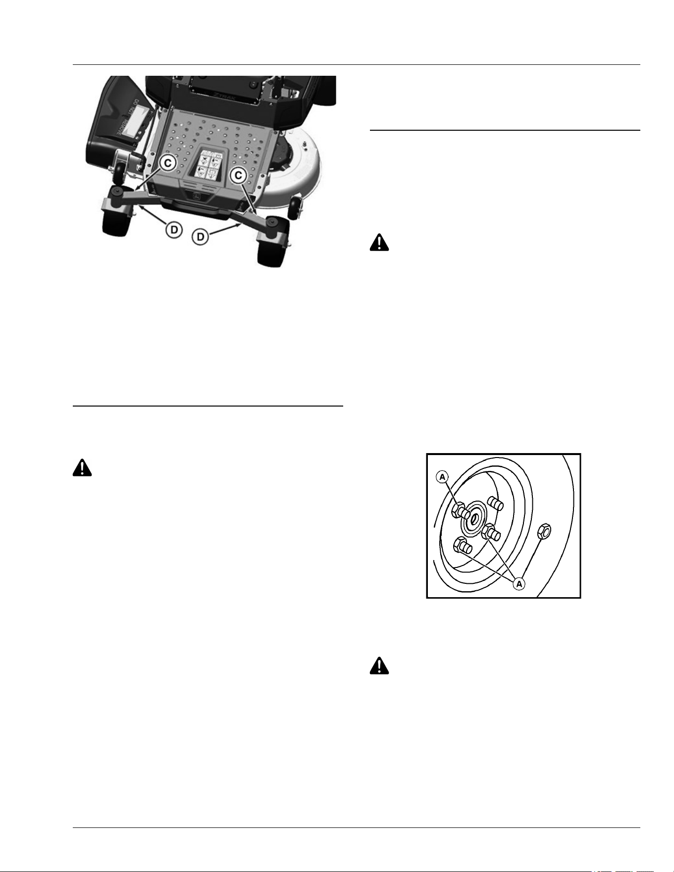
GX536028—UN—25APR22
3. Safely lift front of machine at machine frame points
(C). Place jackstands or other stable supports onto
machine frame locations (D).
4. If lifting only the front of machine, block rear wheels
remaining on ground to avoid movement of machine.
5. To lower the machine, lift front and/or rear of
machine, and remove jackstands or supports. Lower
the machine.
H9PQBYK,0000062-19-17FEB23
Checking Tire Pressure
CAUTION: Avoid injury! Explosive separation of
tire and rim parts is possible when they are
serviced incorrectly:
● Do not attempt to mount a tire without the
proper equipment and experience to perform
the job.
● Make sure that all tires are inated to the
recommended pressure, especially when
operating on slopes. Low pressure can
cause machine to become unstable on
slopes.
● Do not weld or heat a wheel and tire
assembly. Heat can cause an increase in air
pressure resulting in an explosion. Welding
can structurally weaken or deform the wheel.
● Do not stand in front or over the tire
assembly when inating. Use a clip-on chuck
and extension hose long enough to allow
you to stand to one side.
1. Check tires for damage.
2. Check tire pressure with an accurate low-pressure
gauge.
3. A lower pressure will improve traction and
performance depending on turf conditions or if
transport areas have steep inclines.
4. Add or remove air to meet specied tire pressure.
(See Specications section for recommended tire
pressures.)
MP47322,00F4677-19-10JUN20
Removing and Installing Wheel Assembly
Removing
1. Park machine safely. (See Parking Safely in the
Safety section.)
CAUTION: Avoid injury! The machine can fall or
slip from an unsafe lifting device or supports.
● Use a safe lifting device rated for the load to
be lifted.
● Lower machine onto jack stands or other
stable supports and block wheels before
servicing.
IMPORTANT: Avoid damage! Place jack stands
under frame, not under transmission or engine,
when raising or supporting machine.
2. Raise machine with a safe lifting device and lower
machine onto jack stands or other stable supports.
Block wheels remaining on the ground to prevent
machine movement.
MXAL42875—UN—09APR13
3. Remove the wheel nuts (A).
4. Remove the wheel assembly.
CAUTION: Avoid injury! Explosive separation of
tire and rim parts is possible when they are
serviced incorrectly:
● Do not attempt to mount a tire without the
proper equipment and experience to perform
the job.
5. Take wheel assembly to a John Deere dealer or other
service provider for repairs.
Service Miscellaneous
65-2
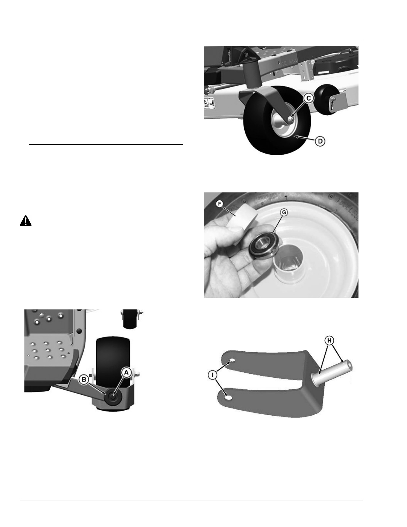
Installing
1. Install wheel assembly with valve stem to the
outside.
2. Tighten wheel nuts evenly in alternating sequence
until snug.
3. Lower machine completely to the ground.
4. Tighten wheel nuts to specication.
Specication
Wheel Nuts—Torque. . . . . . . . . . . . . . . . . . . . . 102 N·m (75 lb.-ft.)
MP47322,00F4678-19-17OCT25
Removing and Installing Front Caster
Wheels
Disassembly:
1. Park machine safely. (See Park Machine Safely in
the Safety section.)
CAUTION: Avoid injury! The machine can fall or
slip from an unsafe lifting device or supports.
● Use a safe lifting device rated for the load to
be lifted.
● Lower machine onto jackstands or other
stable supports and block wheels before
servicing.
NOTE: Remove all attachments prior to lifting machine.
2. Jack up front of machine and place on safety stands.
GX536029—UN—25APR22
3. Support caster assembly and remove ange bolt (A)
and cap (B).
4. Remove caster from machine.
5. Inspect bearings at top and bottom of frame. Replace
worn or damaged bearings.
NOTE: Inner race extends above outer race.
GX536030—UN—25APR22
6. Remove nut (C) and pull bolt out of caster.
7. Remove wheel assembly (D).
MXAL47140—UN—16APR13
8. Remove shield (F) and bearing (G). Inspect shields,
wheel, and bearings for wear or damage. Replace
worn or damaged parts.
GXT002156—UN—02JUN15
9. Inspect bearing wear areas (H), and bolt holes (I) for
wear or damage. Replace if necessary.
Assembly
● Apply grease to caster shaft and bolt.
● Assemble in the reverse order of disassembly.
● Tighten caster locknut and bolt to specication.
Service Miscellaneous
65-3

Specication
Caster Locknut—Torque. . . . . . . . . . . . . . . . . . . . 47 N·m (35 lb·ft)
● Tighten ange bolt securing yoke to specication.
Specication
Flange Bolt—Torque. . . . . . . . . . . . . . . . . . . . . . . 47 N·m (35 lb·ft)
H9PQBYK,0000063-19-13JUN22
Cleaning and Repairing Metal Surfaces
Cleaning:
Follow automotive practices to care for your vehicle’s
painted metal surfaces. Use a high-quality automotive
wax regularly to maintain the factory look of your
vehicle’s painted surfaces.
Repairing Minor Scratches (surface scratch):
1. Clean area to be repaired thoroughly.
IMPORTANT: Avoid damage! Do not use rubbing
compound on painted surfaces.
2. Use automotive polishing compound to remove
surface scratches.
3. Apply wax to entire surface.
Repairing Deep Scratches (bare metal or primer
showing):
1. Clean area to be repaired with rubbing alcohol or
mineral spirits.
2. Use paint stick with factory-matched colors available
from your service provider to ll scratches. Follow
directions included on paint stick for use and for
drying.
3. Smooth out surface using an automotive polishing
compound. Do not use power buer.
4. Apply wax to surface.
MP47322,00F467A-19-16JUL25
Service Miscellaneous
65-4

Using Troubleshoot Chart
If you are experiencing a problem that is not listed in this chart, see
your Technical Manual, dealer, or other service provider for service.
MP47322,00F467B-19-17OCT25
Engine
IF CHECK
Poor Engine Performance Dirt in fuel system or fuel is old.
Replace fuel with fresh stabilized
fuel. Obtain fuel from another
supplier before suspecting
machine problems. Suppliers
blend fuels dierently and
changing suppliers will generally
solve any performance problems
Fuel blended with alcohol or
ether may contribute to
performance problems by
causing gum and varnish
deposits, especially if fuel is
stored for several weeks or more.
Obtain fresh fuel.
Engine Will Not Start - No Crank Park brake not locked.
Motion control levers not in
outward position.
Mower is engaged.
Defective brake, mower
engagement, or key switch.
Electrical problem - See
Electrical Troubleshooting
Section
Engine Cranks But Will Not Start Spark plug wire is loose or
disconnected.
Improper fuel.
Plugged fuel lter.
Electrical problem - See
Electrical Troubleshooting
Section
Engine Is Hard To Start Carburetor is not adjusted
properly or dirty.
Choke not fully closing.
Plugged fuel lter.
Faulty spark plug.
Stale or improper fuel.
Loose or corroded electrical
connections.
Engine oil viscosity.
Engine Runs Unevenly Cooling ns plugged.
Loose electrical connections.
Choke or throttle cable sticking.
Choke not fully open.
Fuel line or fuel lter plugged.
Stale or dirty fuel.
Improper fuel.
Air cleaner element plugged.
Engine Misses Under Load Faulty spark plug.
Stale or dirty fuel.
Plugged fuel lter.
Engine Vapor Locks Fuel tank vent plugged.
Dirt in fuel lter.
Cooling ns plugged.
Loose hose connection at fuel
lter or fuel pump.
IF CHECK
Engine Overheats Engine air intake screen
plugged.
Cooling ns plugged.
Engine oil low or too high.
Engine operated too long at a
slow idle speed.
Engine Will Not Idle Spark plug not gapped correctly.
Faulty spark plug.
Operator raising o the seat.
Engine Knocks Stale or low octane fuel.
Engine overloaded.
Low engine speed.
Oil level low.
Engine Stops Or Misses When
Operating On Hillsides
Fuel tank less than half full of
fuel.
Operator raising o of the seat.
Engine Backres Faulty spark plug.
Operator raising o of the seat.
Engine Loses Power Engine overheating.
Too much oil in engine.
Dirty air cleaner.
Faulty spark plug.
Travel speed is too fast for
conditions.
Improper fuel.
Excessive Fuel Consumption Choke is not fully open.
Black Exhaust Smoke Air lter is dirty or oil soaked.
TH84124,0000246-19-06JUL15
Electrical
IF CHECK
Starter Does Not Work Or Will
Not Turn Engine
Park brake not locked.
Mower is engaged.
Battery terminals are corroded.
Battery not charged.
Motion control levers not in Start/
Shutdown position.
Blown fuse.
Defective key switch
Battery Will Not Charge Dead cell in the battery.
Blown charging fuse.
Battery cables and terminals are
dirty.
Low engine speed or excessive
idling.
Lights Do Not Work Light plug disconnected.
Loose or burned out bulb.
Blown headlight fuse.
MP47322,00F467D-19-15MAR13
Troubleshooting
70-1

Machine
IF CHECK
Machine Vibrates Too Much or
Rattles Excessively
Attachment drive belts worn or
damaged.
Mower blades not balanced.
Traction drive belt damaged or
worn.
Dirt on drive sheaves.
Machine Does Not Move with
Machine Running
Transmission hydraulic oil level
low.
Transmission belt broken.
Bypass valve levers are
engaged.
Front of Machine Squeaks While
Driving
Lubricate mower front draft rod at
front and rear pivot points.
GH8XT3T,00009D8-19-04SEP23
Mower
IF CHECK
Discharge Chute Plugged Travel speed too fast.
Grass too long.
Grass too wet.
Machine rpm not at mow
position.
Restricted air ow.
Belt installed incorrectly.
Adjust cutting height to remove
only 1/3 of grass at a time.
Patches Of Grass Uncut Travel speed too fast.
Engine rpm not at mow position.
Mower deck needs cleaning.
Belt Slipping Debris in sheaves.
Worn belt.
Belt tension is incorrect.
Too Much Vibration Debris on mower deck or in
sheaves.
Damaged drive belt.
Damaged sheaves or sheaves
out of alignment.
Blades out of balance.
Blades Scalping Grass Cutting too low.
Mower wheels not adjusted
correctly.
Turning speed too fast.
Ridges in terrain.
Rough or uneven terrain.
Low tire pressure.
Mower Loads Down Tractor Machine rpm too low.
Travel speed too fast.
Debris wrapped around mower
spindles.
Adjust cutting height to remove
only 1/3 of grass at a time.
Uneven Cut Mower deck not leveled properly.
Travel speed too fast.
Blades dull.
Mower wheels not adjusted
correctly.
Tire pressure unequal.
Adjust cutting height to remove
only 1/3 of grass at a time.
Excessive Clippings are Conditions may be too dry or
IF CHECK
Expelled from Front of Mower
Deck
terrain too uneven to provide
good seal between front of deck
and grass. Visit http://JDParts.
deere.com or contact John
Deere dealer or other purchase
provider to purchase dry
condition kit.
TH84124,00001B2-19-17OCT25
MulchControl (If Equipped)
IF Check
MulchControl™ gate will not
open
Plugging of mower deck/baes.
MulchControl™ gate will not
close
Plugging of mower deck/baes
MulchControl™ gate not holding
setting (open or closed)
Check for handle seated rmly
onto pin taper and properly
aligned.
MulchControl™ causing blowout
in closed position
Check that gate stop is installed
(after removal of cut and throw -
42 inch Accel Deep™ only)
Ensure that system is in closed
position
MulchControl™ Material
Dispersion Not Satisfactory
Clean debris buildup from
underside of deck
Check blades for sharpness and
damage
Ensure that correct blades are
installed (MulchControl™ is
designed to use mulch blades,
not standard blades)
Change blades
Check discharge chute for
damage
Check procedures on Adjusting
Mower Level Side-to-Side and
Front-to-Rear.
Adjust system for proper door
position
Mowing too fast for grass
conditions
MulchControl is a trademark of Deere & Company
Accel Deep is a trademark of Deere & Company
SB31882,00003DC-19-10NOV22
Troubleshooting
70-2

Storing Safety
CAUTION: Avoid injury! Fuel vapors are
explosive and ammable.
Engine exhaust fumes contain carbon
monoxide and cause serious illness or death:
● Run the engine only long enough to move
the machine to or from storage.
● If a machine is stored before allowing it to
cool, machine res and structure res can
occur. Fires can occur if debris is not
removed from around the engine and muer,
or if stored near combustible materials.
● Do not store vehicle with fuel in the tank
inside a building where fumes reach an open
ame or spark.
● Allow the engine to cool before storing the
machine in any enclosure.
MP47322,00F4680-19-06MAY15
Preparing Machine for Storage
1. Repair any worn or damaged parts. Replace parts if
necessary. Tighten loose hardware.
2. To prevent rust, repair scratched or chipped metal
surfaces.
3. Remove grass and debris from machine.
4. Clean under the rotary deck and remove grass and
debris from inside chute and bagger, if applicable.
5. Wash the machine and apply wax to metal and
plastic surfaces.
6. To dry belts and pulleys, run machine for ve
minutes.
7. To prevent rust, apply light coat of engine oil on pivot
and wear points.
8. Lubricate grease points and check tire pressure.
MP47322,00F4681-19-13JUL16
Preparing Fuel and Engine For Storage
Fuel:
If you have been using “Stabilized Fuel,” add stabilized
fuel to tank until the tank is full.
NOTE: Filling the fuel tank reduces the amount of air in
the fuel tank and helps reduce deterioration of fuel.
If you are not using “Stabilized Fuel”:
1. Park machine safely in a well-ventilated area. (See
Parking Safely in the Safety section.)
NOTE: Try to anticipate the last time the machine will be
used for the season so very little fuel is left in the
fuel tank.
2. Turn on engine and allow to run until it runs out of
fuel.
3. For machines equipped with key switch, turn key to
o position.
IMPORTANT: Avoid damage! Stale fuel can produce
varnish and plug carburetor or injector
components and aect engine performance.
● Add fuel conditioner or stabilizer to fresh fuel
before lling tank.
4. Mix fresh fuel and fuel stabilizer in separate
container. Follow stabilizer instructions for mixing.
5. Fill fuel tank with stabilized fuel.
6. Run engine for a few minutes to allow fuel mixture to
circulate through carburetor on gas engine or fuel
injectors on diesel engine.
Engine:
Engine storage procedure should be used when vehicle
is not to be used for longer than 60 days.
1. Change engine oil and lter while engine is warm.
2. Service air lter if necessary.
3. Clean debris from engine air intake screen.
4. On gas engines:
● Remove spark plugs. Put 30 mL (1 oz) of clean
engine oil in cylinders.
● Install spark plugs, but do not connect spark plug
wires.
● Crank the engine 5 or 6 times to allow oil to be
distributed.
5. Clean the engine and engine compartment.
6. Remove battery.
7. Clean the battery and battery posts. Check the
electrolyte level if your battery is not maintenance
free.
8. Close fuel shuto valve if your machine is equipped.
9. Store the battery in a cool, dry place where it will not
freeze.
NOTE: The stored battery should be recharged every 90
days.
10. Charge the battery.
IMPORTANT: Avoid damage! Prolonged exposure to
sunlight could damage surfaces. Store machine
inside or use a cover if stored outside.
Storage
75-1

11. Store the vehicle in a dry, protected place. If vehicle
is stored outside, put a waterproof cover over it.
OUMX068,000077B-19-05JUL17
Removing Machine From Storage
1. Check tire pressure.
2. Check engine oil level.
3. Check battery electrolyte level if your battery is not
maintenance free. Charge battery if necessary.
4. Install battery.
5. On gas engines: check spark plug gap. Install and
tighten plugs to specied torque.
6. Lubricate all grease points.
7. Open fuel shut-o valve if your machine is equipped.
8. Run the engine 5 minutes without the mower or any
attachments running to allow oil to be distributed
throughout engine.
9. Be sure all shields and guards or deectors are in
place.
MP47322,00F4683-19-17FEB23
Storage
75-2

Engine
Z315E Engine
Make . . . . . . . . . . . . . . . . . . . . . . . . . . . . . . . . Briggs & Stratton
Engine Model . . . . . . . . . . . . . . . . . . . . . . . . . . . . . . . . . . 40EXi
Power Rating Information . . . . . . http://www.briggsandstratton.com/
Bore . . . . . . . . . . . . . . . . . . . . . . . . . . . . . . . . 75.4 mm (2.97 in)
Stroke . . . . . . . . . . . . . . . . . . . . . . . . . . . . . . . 73.4 mm (2.89 in)
Displacement. . . . . . . . . . . . . . . . . . . . . . . . . 656 cm
3
(40.03 in³)
Cylinders. . . . . . . . . . . . . . . . . . . . . . . . . . . . . . . . . . . . . . . Twin
Cycle . . . . . . . . . . . . . . . . . . . . . . . . . . . . . . . . . . . . . . . . . Four
Valve Clearance - Intake . . . . . . 0.10 - 0.15 mm (0.004 - 0.006 in)
Valve Clearance - Exhaust . . . . . 0.10 - 0.15 mm (0.004 - 0.006 in)
Spark Plug Gap . . . . . . . . . . . . . . . . . . . . . . . 0.75 mm (0.030 in)
Spark Plug Torque . . . . . . . . . . . . . . . . . . . . . . 20 N·m (180 lb·in)
Z320MEngine
Make . . . . . . . . . . . . . . . . . . . . . . . . . . . . . . . . . . . . . Kawasaki
Engine Model . . . . . . . . . . . . . . . . . . . . . . . . . . . . . . . . FR651V
Power Rating Information . . . http://www.kawasakienginesusa.com/
Bore . . . . . . . . . . . . . . . . . . . . . . . . . . . . . . . . . .78 mm (3.07 in)
Stroke . . . . . . . . . . . . . . . . . . . . . . . . . . . . . . . . .76 mm (2.99 in)
Displacement. . . . . . . . . . . . . . . . . . . . . . . . . 726 cm
3
(44.30 in³)
Cylinders. . . . . . . . . . . . . . . . . . . . . . . . . . . . . . . . . . . . . . . Twin
Cycle . . . . . . . . . . . . . . . . . . . . . . . . . . . . . . . . . . . . . . . . . Four
Valve Clearance - Intake . . . . 0.075 - 0.125 mm (0.002 - 0.005 in)
Valve Clearance - Exhaust . . . 0.075 - 0.125 mm (0.002 - 0.005 in)
Spark Plug Gap . . . . . . . . . . . . . . . . . . . . . . . 0.75 mm (0.030 in)
Spark Plug Torque . . . . . . . . . . . . . . . . . . . . . . 20 N·m (180 lb·in)
Z320R Engine
Make . . . . . . . . . . . . . . . . . . . . . . . . . . . . . . . . . . . . . Kawasaki
Engine Model . . . . . . . . . . . . . . . . . . . . . . . . . . . . . . . . FR651V
Power Rating Information . . . http://www.kawasakienginesusa.com/
Bore . . . . . . . . . . . . . . . . . . . . . . . . . . . . . . . . . .78 mm (3.07 in)
Stroke . . . . . . . . . . . . . . . . . . . . . . . . . . . . . . . . .76 mm (2.99 in)
Displacement. . . . . . . . . . . . . . . . . . . . . . . . . 726 cm
3
(44.30 in³)
Cylinders. . . . . . . . . . . . . . . . . . . . . . . . . . . . . . . . . . . . . . . Twin
Cycle . . . . . . . . . . . . . . . . . . . . . . . . . . . . . . . . . . . . . . . . . Four
Valve Clearance - Intake . . . . 0.075 - 0.125 mm (0.002 - 0.005 in)
Valve Clearance - Exhaust . . . 0.075 - 0.125 mm (0.002 - 0.005 in)
Spark Plug Gap . . . . . . . . . . . . . . . . . . . . . . . 0.75 mm (0.030 in)
Spark Plug Torque . . . . . . . . . . . . . . . . . . . . . . 20 N·m (180 lb·in)
Z325E Engine
Make . . . . . . . . . . . . . . . . . . . . . . . . . . . . . . . . Briggs & Stratton
Engine Model . . . . . . . . . . . . . . . . . . . . . . . . . . . . . . . . . 44 EXi
Power Rating Information . . . . . . http://www.briggsandstratton.com/
Bore . . . . . . . . . . . . . . . . . . . . . . . . . . . . . . . 79.25 mm (3.12 in)
Stroke . . . . . . . . . . . . . . . . . . . . . . . . . . . . . . . 73.4 mm (2.89 in)
Displacement. . . . . . . . . . . . . . . . . . . . . . . . . 724 cm
3
(44.18 in³)
Cylinders. . . . . . . . . . . . . . . . . . . . . . . . . . . . . . . . . . . . . . . Twin
Cycle . . . . . . . . . . . . . . . . . . . . . . . . . . . . . . . . . . . . . . . . . Four
Valve Clearance - Intake . . . . . . 0.10 - 0.15 mm (0.004 - 0.006 in)
Valve Clearance - Exhaust . . . . . 0.10 - 0.15 mm (0.004 - 0.006 in)
Spark Plug Gap . . . . . . . . . . . . . . . . . . . . . . . 0.75 mm (0.030 in)
Spark Plug Torque . . . . . . . . . . . . . . . . . . . . . . 20 N·m (180 lb·in)
Z330M Engine
Make . . . . . . . . . . . . . . . . . . . . . . . . . . . . . . . . . . . . . Kawasaki
Engine Model . . . . . . . . . . . . . . . . . . . . . . . . . . . . . . . . FR691V
Power Rating Information . . . http://www.kawasakienginesusa.com/
Bore . . . . . . . . . . . . . . . . . . . . . . . . . . . . . . . . . .78 mm (3.07 in)
Stroke . . . . . . . . . . . . . . . . . . . . . . . . . . . . . . . . .76 mm (2.99 in)
Displacement. . . . . . . . . . . . . . . . . . . . . . . . . 726 cm
3
(44.30 in³)
Cylinders. . . . . . . . . . . . . . . . . . . . . . . . . . . . . . . . . . . . . . . Twin
Cycle . . . . . . . . . . . . . . . . . . . . . . . . . . . . . . . . . . . . . . . . . Four
Valve Clearance - Intake . . . . 0.075 - 0.125 mm (0.002 - 0.005 in)
Valve Clearance - Exhaust . . . 0.075 - 0.125 mm (0.002 - 0.005 in)
Spark Plug Gap . . . . . . . . . . . . . . . . . . . . . . . 0.75 mm (0.030 in)
Spark Plug Torque . . . . . . . . . . . . . . . . . . . . . . 20 N·m (180 lb·in)
Z330R Engine
Make . . . . . . . . . . . . . . . . . . . . . . . . . . . . . . . . . . . . . Kawasaki
Engine Model . . . . . . . . . . . . . . . . . . . . . . . . . . . . . . . . FR691V
Power Rating Information . . . http://www.kawasakienginesusa.com/
Bore . . . . . . . . . . . . . . . . . . . . . . . . . . . . . . . . . .78 mm (3.07 in)
Stroke . . . . . . . . . . . . . . . . . . . . . . . . . . . . . . . . .76 mm (2.99 in)
Displacement. . . . . . . . . . . . . . . . . . . . . . . . . 726 cm
3
(44.30 in³)
Cylinders. . . . . . . . . . . . . . . . . . . . . . . . . . . . . . . . . . . . . . . Twin
Cycle . . . . . . . . . . . . . . . . . . . . . . . . . . . . . . . . . . . . . . . . . Four
Valve Clearance - Intake . . . . 0.075 - 0.125 mm (0.002 - 0.005 in)
Valve Clearance - Exhaust . . . 0.075 - 0.125 mm (0.002 - 0.005 in)
Spark Plug Gap . . . . . . . . . . . . . . . . . . . . . . . 0.75 mm (0.030 in)
Spark Plug Torque . . . . . . . . . . . . . . . . . . . . . . 20 N·m (180 lb·in)
GH8XT3T,00008D4-19-13JUL22
Drivetrain
Transaxle Motors (Z315E, Z320M, Z320R) 42A deck . . Hydro-Gear
EZT-C
Transaxle Motors (Z325E, Z330M, Z330R) 48A/54A deck. . Hydro-
Gear EZT-D
Number of Speeds. . . . . . . . . . . . . . . Hydrostatic, Variable Speed
GH8XT3T,00008D5-19-10MAY22
Travel Speeds at Full Engine RPM
Forward . . . . . . . . . . . . . . . . . . . . . . . . .0-11.3 km/h (0-7.0 mph)
Reverse . . . . . . . . . . . . . . . . . . . . . . . . . 0-5.6 km/h (0-3.5 mph)
SB31882,00003D9-19-14APR20
Specications
80-1

Electrical System
Battery Type . . . . . . . . . . . . . . . . . . . . . . . . . . . . . . . . . . 12 Volt
Cold Cranking Capacity . . . . . . . . . . . . . . . . . . . . . . . . 300 Amps
TH84124,00001B5-19-12JUN15
Fuel System
Fuel Types (Recommended):
. . . . . . . . . . . . . . . . . . . Regular Grade 87 Octane Unleaded Fuel
. . . . . . . . . . . . . . . . . . . . . . . . Ethanol Blended Fuel (Up to 10%)
. . . . . . . . . . . . . . . . . . . . . MTBE Reformulated Fuel (Up to 15%)
Fuel Filter . . . . . . . . . . . . . . . . . . . . Replaceable - paper element
Fuel Pump . . . . . . . . . . . . . . . . . . . . . . . . . . . . . . . . . . . . Pulse
Fuel Delivery . . . . . . . . . . . . . . . . . . . . . . . . . . . . . . . .Carburetor
GH8XT3T,00009F8-19-11MAY22
Tires
Front. . . . . . . . . . . . . . . . . . . . . . . . . . . . . . . . . . . . . . . . 11x6-5
Rear (EZ370R) . . . . . . . . . . . . . . . . . . . . . . . . . . . 20x10-8 (Turf)
Rear (EZ370R) . . . . . . . . . . . . . . . . . . . . . . . . . . 18x8.5-8 (Turf)
Ination - Front . . . . . . . . . . . . . . . . . . . . . . . . . 103 kPa (15 psi)
Ination - Rear. . . . . . . . . . . . . . . . . . . . . . . . . . . 69 kPa (10 psi)
GH8XT3T,00008C7-19-02DEC22
Capacities
Crankcase with oil lter (Z315E, Z325E) . . . . . . . . . . 1.9 L (2.0 qt)
Crankcase with oil lter (Z320M, Z320R, Z330R) . . . . 2.1 L (2.2 qt)
Fuel Tank . . . . . . . . . . . . . . . . . . . . . . . . . . . . . 11.36 L (3.0 gal)
Towing Capacity (All Models) . . . . . . . . . . . . . . 113.39 kg (250 lb)
Maximum Tongue Load . . . . . . . . . . . . . . . . . . . .45.4 kg (100 lb)
gh8xt3t,1657776738887-19-21AUG23
Dimensions
Z315E with 42A
Height . . . . . . . . . . . . . . . . . . . . . . . . . . . . . . . 1056 mm (36.4 in)
Width . . . . . . . . . . . . . . . . . . . . . . . . . . . . . . . 1280 mm (50.4 in)
Length . . . . . . . . . . . . . . . . . . . . . . . . . . . . . . 1915 mm (75.4 in)
Weight with Mower and Full Fuel . . . . . . . . . . . . 252 kg (554.4 lb)
Z320M with 42A
Height . . . . . . . . . . . . . . . . . . . . . . . . . . . . . . . 1100 mm (43.3 in)
Width/Hitch . . . . . . . . . . . . . . . . . . . . . . . . . . . 1280 mm (50.4 in)
Length . . . . . . . . . . . . . . . . . . . . . . . . . . . . . . 1975 mm (77.8 in)
Weight with Mower and Full Fuel . . . . . . . . . . . . . 255 kg (561 lb)
Z320R with 42A
Height . . . . . . . . . . . . . . . . . . . . . . . . . . . . . . . 1100 mm (43.3 in)
Width/Hitch . . . . . . . . . . . . . . . . . . . . . . . . . . . 1280 mm (50.4 in)
Length . . . . . . . . . . . . . . . . . . . . . . . . . . . . . . 1836 mm (72.3 in)
Weight with Mower and Full Fuel . . . . . . . . . . . . . 260 kg (572 lb)
Z325E with 48A
Height . . . . . . . . . . . . . . . . . . . . . . . . . . . . . . . 1080 mm (42.5 in)
Width . . . . . . . . . . . . . . . . . . . . . . . . . . . . . . . 1590 mm (62.6 in)
Length . . . . . . . . . . . . . . . . . . . . . . . . . . . . . . 1915 mm (75.4 in)
Weight With Mower and Full Fuel . . . . . . . . . . . . . 270 kg (594 lb)
Z325E with 54A
Height . . . . . . . . . . . . . . . . . . . . . . . . . . . . . . . 1080 mm (42.5 in)
Width . . . . . . . . . . . . . . . . . . . . . . . . . . . . . . . 1735 mm (68.5 in)
Length . . . . . . . . . . . . . . . . . . . . . . . . . . . . . . 1915 mm (75.4 in)
Weight with Mower and Full Fuel . . . . . . . . . . . . . 275 kg (605 lb)
Z330M with 48A
Height . . . . . . . . . . . . . . . . . . . . . . . . . . . . . . . 1123 mm (44.2 in)
Width . . . . . . . . . . . . . . . . . . . . . . . . . . . . . . . 1590 mm (62.6 in)
Length . . . . . . . . . . . . . . . . . . . . . . . . . . . . . . 1975 mm (77.8 in)
Weight with Mower and Full Fuel . . . . . . . . . . . . . 272 kg (598 lb)
Z330M with 54A
Height . . . . . . . . . . . . . . . . . . . . . . . . . . . . . . . 1123 mm (44.2 in)
Width . . . . . . . . . . . . . . . . . . . . . . . . . . . . . . . 1740 mm (68.5 in)
Length . . . . . . . . . . . . . . . . . . . . . . . . . . . . . . 1975 mm (77.8 in)
Weight with Mower and Full Fuel . . . . . . . . . . . . . 265 kg (584 lb)
Z330R with 48A
Height . . . . . . . . . . . . . . . . . . . . . . . . . . . . . . . 1123 mm (44.2 in)
Width . . . . . . . . . . . . . . . . . . . . . . . . . . . . . . . 1590 mm (62.6 in)
Length . . . . . . . . . . . . . . . . . . . . . . . . . . . . . . 1975 mm (77.8 in)
Weight with Mower and Full Fuel . . . . . . . . . . . . . 278 kg (611 lb)
Z330R with 54A
Height . . . . . . . . . . . . . . . . . . . . . . . . . . . . . . . 1123 mm (44.2 in)
Width . . . . . . . . . . . . . . . . . . . . . . . . . . . . . . . 1740 mm (68.5 in)
Length . . . . . . . . . . . . . . . . . . . . . . . . . . . . . . 1975 mm (77.8 in)
Weight with Mower and Full Fuel . . . . . . . . . . . . . 283 kg (623 lb)
GH8XT3T,00008D6-19-06MAY22
Recommended Lubricants
Engine Oil . . . . . . . . . . . . . . . . . . . . TURF-GARD® OR PLUS-4®
Grease
Specications
80-2

. . . . . . . . . . . . . . . . . . . . . . . . . GREASE-GARD™ Premium Plus
. . . . . . . . John Deere Multi-Purpose HD Lithium Complex Grease
(Specications and design subject to change without
notice.)
TH84124,000016C-19-03MAR15
Mower Decks
42A Mower
Cutting Width. . . . . . . . . . . . . . . . . . . . . . . . . . . . . 1.07 m (42 in)
Blades-Rotary . . . . . . . . . . . . . . . . . . . . . . . . . . . . . . . . . . . . . 2
Blade Bolt Torque . . . . . . . . . . . . . . . . . . . . . . . 68 N•m (50 lb·ft)
Cutting Height (Approximately) . . . . . . 32 - 114 mm (1.25 - 4.5 in)
48A Mower
Cutting Width. . . . . . . . . . . . . . . . . . . . . . . . . . . . . 1.22 m (48 in)
Blades-Rotary . . . . . . . . . . . . . . . . . . . . . . . . . . . . . . . . . . . . . 3
Blade Nut Torque. . . . . . . . . . . . . . . . . . . . . . . . 68 N•m (50 lb·ft)
Cutting Height (Approximately) . . . . . . 32 - 114 mm (1.25 - 4.5 in)
54A Mower
Cutting Width. . . . . . . . . . . . . . . . . . . . . . . . . . . . . 1.37 m (54 in)
Blades-Rotary . . . . . . . . . . . . . . . . . . . . . . . . . . . . . . . . . . . . . 3
Blade Nut Torque. . . . . . . . . . . . . . . . . . . . . . . . 68 N•m (50 lb·ft)
Cutting Height (Approximately) . . . . . . 32 - 114 mm (1.25 - 4.5 in)
GH8XT3T,00009E0-19-06MAY22
Specications
80-3

Product Warranty
John Deere oers a standard warranty on new John
Deere products. For a copy of the product warranty
statement or for details on the warranty terms and
conditions for products purchased in the United States
and Canada, please contact your local John Deere
Dealer or utilize the following resources:
United States
Website:
http://www.deere.com/en_US/services_and_support/
warranty/warranty.page
Toll Free: 1-800-537-8233
Dealer Locator:
http://dealerlocator.deere.com/servlet/country=US
Canada
Website (English):
http://www.deere.ca/en_CA/services_and_support/
service_plans_warranties/service_plans_warranties.
page
Website (French):
http://fr.deere.ca/en_CA/services_and_support/
service_plans_warranties/service_plans_warranties.
page
Toll Free: 1-800-537-8233
Dealer Locator:
http://dealerlocator.deere.com/servlet/country=CA
Emission-related warranties are included in this
Operator’s Manual, and applicable if required by law
or regulation.
For products purchased in a country other than the
United States or Canada, please contact your local
John Deere dealer for assistance.
MP47322,00F4690-19-27FEB24
U.S. EPA Emission Control System
Warranty Statement (O-Road Engine
Equipment)
Your Warranty Rights and Obligations
John Deere and the United States Environmental
Protection Agency are pleased to explain the emission
control system's warranty on your o-road engine
equipment. John Deere must warrant the emission
control system on your o-road engine equipment for
the period listed below provided there has been no
abuse, neglect or improper maintenance of your o-
road engine equipment leading to the failure of the
emission control system.
Manufacturer’s Warranty Coverage
Your evaporative emission control system is warranted
for two years. Your o-road engine is warranted as
follows: If your o-road engine equipment has a Briggs
& Stratton engine, your o-road engine is warranted for
two years. For all other o-road engines referenced in
this Operator's Manual, your o-road engine is
warranted for three years. If any emission-related part
on your o-road equipment is defective, the part will be
repaired or replaced by John Deere or an authorized
John Deere service provider.
Owner’s Warranty Responsibilities
● As the spark ignited o-road engine equipment
owner, you are responsible for the performance of
the required maintenance listed in your Operator’s
Manual. John Deere recommends that you retain all
receipts covering maintenance on your spark ignited
o-road engine equipment, but John Deere cannot
deny warranty coverage solely for lack of receipts or
for your failure to ensure the performance of all
scheduled maintenance.
● As the spark ignited o-road engine equipment
owner, you should however be aware that John
Deere may deny you warranty coverage if your spark
ignited o-road engine equipment or a part has failed
due to abuse, neglect, or improper maintenance or
unapproved modications.
● You are responsible for presenting your spark ignited
o-road engine equipment to a John Deere Turf and
Compact Utility distribution center or service center
as soon as a problem exists. The warranty repairs
shall be completed in a reasonable amount of time,
not to exceed 30 days. If you have a question about
your emission control warranty coverage, your
emission control warranty rights and responsibilities,
how to make an emission control system warranty
claim or how to make arrangements for emission-
related authorized repairs, you should contact your
John Deere Turf and Compact Utility retailer, or the
John Deere Customer Contact Center at 1-800-537-
8233, or email John Deere from
https://www.deere.com/en/our-company/contact-us/.
General Emission Control System Warranty
Coverage
The warranty period begins on the date the spark
ignited o-road engine equipment is delivered to an
ultimate purchaser. John Deere warrants to the ultimate
purchaser and each subsequent purchaser that the
spark ignited o-road engine equipment is:
● Designed, built and equipped so it conforms at the
time of sale to the ultimate purchaser with applicable
U.S. Environmental Protection Agency regulations
under 40 CFR Parts 1054, 1048 and 1060; and,
● Free from defects in materials and workmanship that
causes the failure of a warranted part to conform with
Warranty
85-1

applicable regulations for the emission control
system warranty period provided herein.
● For owners located more than 100 miles from a John
Deere authorized service center, John Deere will pay
either for shipping costs to and from an authorized
service center, provide for a service technician to
come to the owner to make the warranty repair, or
pay for the repair to be made at a local non-
authorized service center. These provisions do not
apply to high-altitude counties within the following
States: Alaska, Hawaii, Arizona, Colorado, Idaho,
Montana, Nebraska, Nevada, New Mexico, Oregon,
Texas, Utah, and Wyoming.
Emission Control System Warranty Interpretation
● Any warranted part that is not scheduled for
replacement as required by the maintenance
instructions in the Operator's Manual is warranted as
provided herein. If any such part fails during the
period of warranty coverage it will be repaired or
replaced by John Deere or an authorized John Deere
service provider. Any such part repaired or replaced
under warranty is warranted for the remaining
warranty period.
● Any warranted part that is scheduled only for regular
inspection in the maintenance instructions in the
Operator’s Manual is warranted as provided herein.
A statement in the Operator’s Manual to the eect of
“repair or replace as necessary” does not reduce the
period of warranty coverage. Any such part repaired
or replaced under warranty is warranted for the
remaining warranty period.
● Any warranted part that is scheduled for replacement
as required maintenance in the Operator's Manual is
warranted for the period of time prior to the rst
scheduled replacement point for that part. If the part
fails prior to the rst scheduled replacement, the part
will be repaired or replaced by John Deere or an
authorized John Deere service provider. Any such
part repaired or replaced under warranty is
warranted for the remainder of the period prior to the
rst scheduled replacement point for the part.
● Repair or replacement of any warranted part under
the warranty will be performed at no charge to the
owner by John Deere or an authorized John Deere
service provider.
● The owner will not be charged for diagnostic labor
which leads to the determination that a warranted
part is defective, provided such work is performed by
John Deere or an authorized John Deere service
provider.
● John Deere or an authorized John Deere service
provider will repair damages to other engine
components proximately caused by a failure under
warranty of any emission-related warranted part.
● Add-on or modied parts that are not exempted by
the California Air Resources Board may not be used.
The use of any non-exempted add-on or modied
parts will be grounds for disallowing a warranty claim.
John Deere or any authorized John Deere service
provider will not be liable to warrant failures of
warranted parts caused by the use of a non-
exempted add-on or modied part.
Emission Control System Warranty Parts List
Coverage under this warranty includes, but is not limited
to, the parts listed below (the emission control system
parts) to the extent these parts were on the o-road
equipment and engine purchased.
Fuel Metering System:
● Carburetor and internal parts (or fuel injection
system)
● Air/fuel ratio feedback and control system
● Cold start enrichment system
Evaporative System:
● Fuel tank, fuel cap and tether
● Fuel hose, line, ttings, clamps
● Fuel pump, fuel shut-o valve
● Fuel vapor hoses, ttings
● Carbon canister
● Rollover/slant valve for fuel vapor control
● Purge and vent line
Air Induction System:
● Air cleaner
● Intake manifold
Ignition System:
● Spark plugs
● Magneto or electronic ignition system
● Spark advance/retard system
● Gaskets
Lubrication System:
● Oil pump and internal parts
Positive Crankcase Ventilation (PCV) System
● PCV Valve
● Oil ller cap
Exhaust System:
● Exhaust manifold
● Catalyst muer
Miscellaneous Items Used in Above Systems
Warranty
85-2

● Valves and Switches: vacuum, temperature, position,
check, time-sensitive
● Electronic controls
● Hoses, belts, connectors and assemblies
Limited Liability
a) The liability of John Deere under this emission control
system warranty is limited solely to the remedying of
defects in materials or workmanship. Except as
otherwise expressly provided herein, this warranty does
not cover inconvenience or loss of use of the o-road
equipment or engine or transportation of the equipment
or engine to or from the John Deere Turf and Compact
Utility retailer or authorized service provider. John Deere
shall not be liable for any other expense, loss, or
damage, whether direct, incidental, consequential
(except as listed above under "coverage") or exemplary
arising in connection with the sale or use of or inability to
use the o-road equipment or engine for any other
purpose.
b) No express emission control system warranty is given
by John Deere with respect to the equipment or engine
except as specically set forth in this document. Any
emission control system warranty implied by law,
including any warranty of merchantability or tness for a
particular purpose, is expressively limited to the
emission control system warranty terms set forth in this
document.
c) No dealer or service provider is authorized to modify
this Federal, California and John Deere Emission
Control System Warranty.
mk71445,1710421168405-19-22MAR24
Tire Warranty
John Deere warranty applies for tires available through
the John Deere parts system. For tires not available
through the John Deere parts system, the tire
manufacturer’s warranty applicable to your machine
may not apply outside the U.S. (See your John Deere
dealer for specic information.)
MX00654,0000314-19-21AUG14
Limited Battery Warranty For Factory
Installed Batteries
NOTE: Applicable in North America only. For complete
machine warranty, reference a copy of the John
Deere warranty statement. Contact your John
Deere dealer to obtain a copy.
TO SECURE WARRANTY SERVICE
The purchaser must request warranty service from a
John Deere dealer authorized to sell John Deere
batteries, and present the battery to the dealer with the
top cover plate codes intact.
FREE REPLACEMENT PERIOD
Any new battery which becomes unserviceable (not
merely discharged) due to defects in material or
workmanship within the FREE REPLACEMENT
PERIOD will be replaced free of charge. Installation
costs will be covered by warranty if the unserviceable
battery was installed by a John Deere factory or dealer
and the replacement battery is installed by a John
Deere dealer.
PRO RATA ADJUSTMENT (batteries with letter code
identication only)
Any new battery which becomes unserviceable (not
merely discharged) due to defects in material or
workmanship within the Pro Rata Warranty Period will
be replaced upon payment of the battery’s current list
price less a pro rata credit for unused months of service.
The applicable adjustment period is determined from
the Warranty Code printed at the top of the battery and
table below. Installation costs are not covered after the
battery warranty period has ended.
THIS WARRANTY DOES NOT COVER
A. Breakage of the container, cover, or terminals.
B. Depreciation or damage caused by lack of
reasonable and necessary maintenance or by improper
maintenance.
C. Transportation, mailing, or service call charges for
warranty service.
D. Batteries that are merely discharged.
LIMITATION OF IMPLIED WARRANTIES AND
PURCHASER’S REMEDIES
To the extent permitted by law, neither John Deere nor
any company aliated with it makes any warranties,
representations, or promises as to the quality,
performance or freedom from defect of the products
covered by this warranty. IMPLIED WARRANTIES OF
MERCHANTABILITY AND FITNESS FOR A
PARTICULAR PURPOSE, TO THE EXTENT
APPLICABLE, SHALL BE LIMITED IN DURATION TO
THE APPLICABLE ADJUSTMENT PERIOD SET
FORTH HERE. THE PURCHASER’S ONLY
REMEDIES IN CONNECTION WITH THE BREACH OR
PERFORMANCE OF ANY WARRANTY ON JOHN
DEERE BATTERIES ARE THOSE SET FORTH HERE.
IN NO EVENT WILL THE DEALER, JOHN DEERE OR
ANY COMPANY AFFILIATED WITH JOHN DEERE BE
LIABLE FOR INCIDENTAL OR CONSEQUENTIAL
DAMAGES. (Note: Some states do not allow limitations
on how long an implied warranty lasts or the exclusion
or limitation of incidental or consequential damages. So
these limitations and exclusions may not apply to you.)
This warranty gives you specic legal rights, and you
may also have some rights which vary from state to
state.
Warranty
85-3

NO DEALER WARRANTY
The selling dealer makes no warranty of its own and the
dealer has no authority to make any representation or
promise on behalf of John Deere, or to modify the terms
or limitations of this warranty in any way.
WARRANTY TERMS TABLE
NOTE: If your battery is not labeled with a warranty
code, it is a warranty code 6.
Warranty Code Free Replacement
Period
Pro Rata Warranty
Period
A 90 Days 40 Months
B 90 Days 36 Months
C 90 Days 24 Months
D 12 Months 48 Months
E 90 Days 12 Months
F 90 Days 60 Months
G 12 Months 60 Months
H 12 Months 60 Months
6 6 Months 0 Months
12 12 Months 0 Months
18 18 Months 0 Months
OUMX068,0000504-19-18OCT24
Warranty
85-4

John Deere Quality
John Deere equipment is more than just a purchase, it’s
an investment in quality. That quality goes beyond our
equipment to your John Deere dealer’s parts and
service support. This support is needed to keep you a
satised customer.
That’s why John Deere has initiated a process to handle
your questions or problems, should they arise. The
following three steps will help guide you through the
process.
Step 1
Refer to your operator’s manual
A. It has many illustrations and detailed information on
the safe and proper operation of your equipment.
B. It gives troubleshooting procedures, and specication
information.
C. It gives ordering information for parts catalogs,
service and technical manuals.
D. If your questions are not answered in the operator’s
manual, then go to Step 2.
Step 2
Contact your dealer
A. Your John Deere dealer has the responsibility,
authority, and ability to answer questions, resolve
problems, and fulll your parts and service needs.
B. First, discuss your questions or problems with your
dealer’s trained parts and service sta.
C. If the parts and service people are unable to resolve
your problem, see the dealership manager or owner.
D. If your questions or problems are not resolved by the
dealer, then go to Step 3.
Step 3
Contact John Deere
A. Your John Deere dealer is the most ecient source in
addressing any concern, but if you are not able to
resolve your problem after checking your operator’s
manual and contacting your dealer, contact John Deere
for assistance.
B. For prompt, eective service, please have the
following ready before you call:
● The name of the dealer with whom you’ve been
working.
● Your equipment model number.
● Number of hours on machine (if applicable).
● Your serial number which you recorded on the inside
front cover of this manual.
● If the problem is with an attachment, your attachment
identication number.
C. Then call 1-800-537-8233 (United States and
Canada) and our advisor will work with your dealer to
investigate your concern. If you are outside the United
States and Canada, visit the following website:
https://www.deere.com/en/global-country-selector/
Select your country and then click on the Contact Us link
at the bottom of the page.
SP66632,00043A7-19-04AUG25
John Deere Quality Statement
JDQS-1

Record Service Dates
Oil Change Oil Filter Change (If
Equipped)
Lubricate Machine Air Cleaner Element
Check/Clean
Fuel Filter Change
OUO1082,00066CA-19-15MAY17
Service Record
SR-1
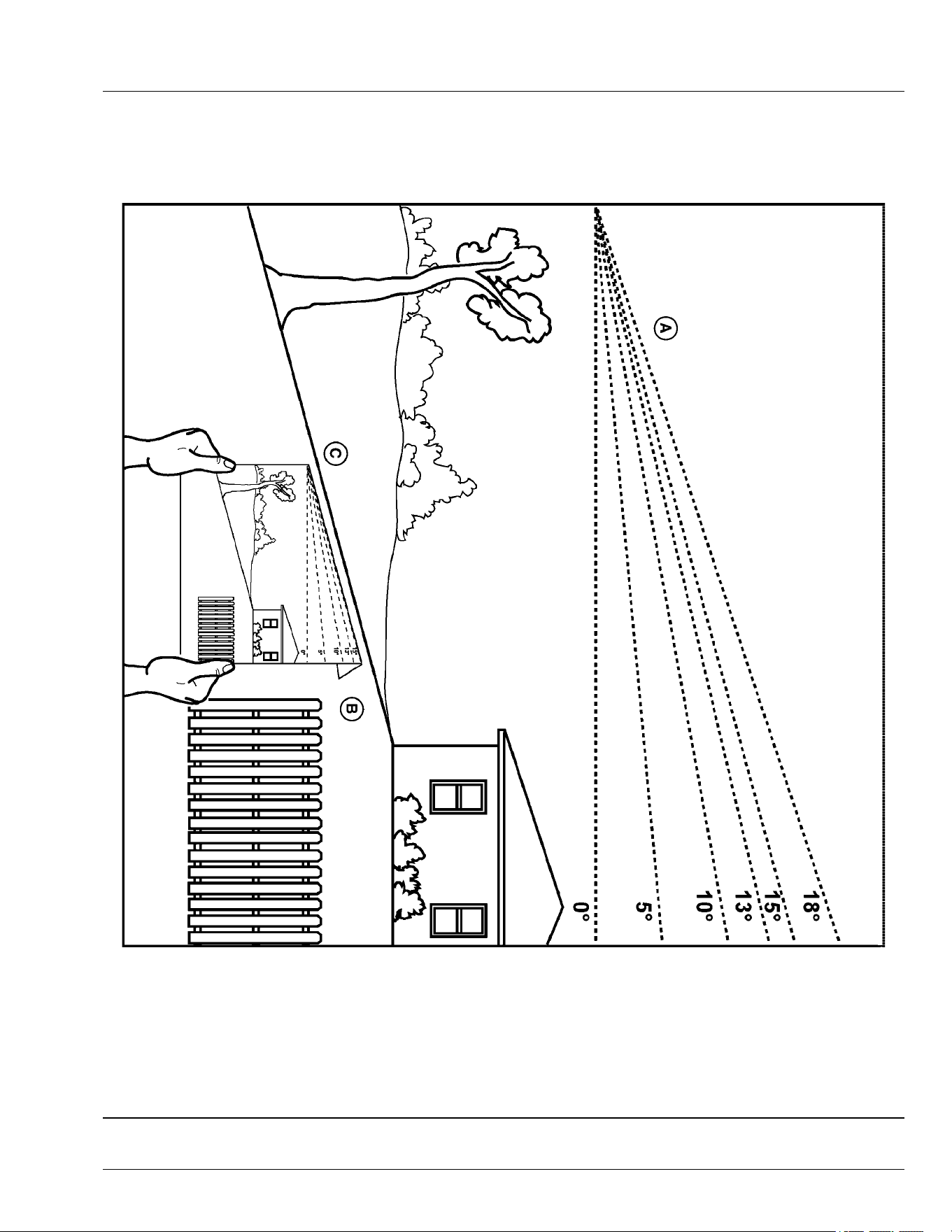
Slope Gauge Template
Hold up or copy this page and follow the directions below to use the Slope Gauge Template.
MXT013189—UN—22APR15
Use this slope gauge to determine if a slope is too steep for safe operation. Do not operate your machine on a slope greater than what is
recommended in your operator’s manual. See Operating on Slopes in the Safety section.
• Fold along the appropriate line (A) to match the recommended slope.
• Align this edge (B) with a vertical surface, a tree, building, fence pole, etc.
• Compare slope (C) with folded edge.
OUMX068,0000513-19-05JUL17
Slope Gauge
SG-1

A
Adjustment, Altitude . .... . .... . ..... ...... ..... ..... . .. 45-1
Air Cleaner Element
Checking and Cleaning ...... . .... . ..... ..... ...... 45-5
Air Cleaner Elements (Twin Cylinder), Checking and
Cleaning .. .... . .... . ..... ..... ...... ..... ..... . .... . . 45-4
B
Battery and Terminals, Cleaning ... . .... . .... . ..... .. 60-1
Battery, Removing and Installing ...... . .... . .... . ... 60-1
Battery, Service Safely ...... ..... ...... ..... ..... . .... 60-1
Battery, Using Booster .. ..... ..... . .... . .... . ..... .... 60-2
Blades, Checking Mower ...... ...... ..... ..... . .... . 55-11
D
Deectors
Installing, 48 in. Accel Deep™ deck ..... ..... . .. 55-9
E
Electrical . .... . .... . ..... ........... ..... . .... . .... . ..... 60-1
Electrical Troubleshooting . .... ...... ........... ..... . 70-1
Emissions
Required language
EPA ........... ..... . .... . .... . ..... ..... ...... ..... ... 2
Emissions Performance
Tampering ....... ..... . .... . .... . ..... ..... ...... ..... ... 2
Engine
Oil . . ..... ..... ...... ..... . .... . .... . ..... ..... ...... .. 45-1
Engine Fins, Cleaning. .... . .... . ..... ........... ..... . 45-3
Engine Shroud, Cleaning .... ...... ..... . .... . .... . ... 45-3
Engine Troubleshooting.......... ..... . .... . .... . ..... 70-1
F
Filter, Changing Engine Oil ...... ..... . .... . .... . ..... 45-2
Filter, Replacing Fuel..... . .... . .... . ..... ..... ...... .. 45-7
Foot Plate, Removing and Installing Mower Deck 55-1
Four-cycle Engine, gasoline fuel. . .... . .... . ..... .... 65-1
Fuel Storage... . .... . ..... ..... ...... ..... . .... . .... . ... 75-1
Fuel Tank, Filling.. . .... . ..... ..... ...... ..... ...... .... 65-1
Fuse, Replacing...... ..... . .... . .... . ..... ..... ...... .. 60-2
G
Gasoline fuel, four-cycle engine . ..... ..... ...... .... 65-1
General Cleaning Guidelines.... ..... . .... . .... . ..... 15-1
Grease .... . .... . .... . ..... ..... ...... ..... . .... . .... . ... 40-1
Guard, Cleaning Engine Screen .... . ..... ..... ...... 45-7
H
Handle
Installing, 48 in. Accel Deep™ deck ..... ..... . . 55-10
Hour Meter, Using ..... ........... ...... .... . .... . ..... 30-7
I
Identication Numbers, Record ... . ..... ..... ...... .. 00-1
J
John Deere Quality ..... ..... ..... . .... . .... . ..... . JDQS-1
L
Labels, Locating Safety ... ..... . .... . ..... ..... ...... . 05-1
Labels, safety with text... . .... . ..... ........... ..... . . 05-2
Labels, safety without text .... ...... ..... ..... . .... . .. 06-2
Levers, Using the Motion Control..... . .... . .... . .... 30-7
Lifting Machine ... . .... . ..... ..... ...... ..... ..... . .... . 65-1
M
Machine Troubleshooting . .... . ..... ........... ..... . . 70-2
Machine, Mounting and Dismounting .... ..... . .... . 30-1
Material Collection System, Unplugging ..... .... . . 30-11
Metal Surfaces, Repairing and Cleaning . . .... . .... 65-4
Motion Control Levers, Adjusting ...... ..... ..... . ... 30-1
Move Machine by Hand.. ..... ...... ..... ..... . .... . . 30-11
Mower Deck Identication .... . ..... ........... ..... . . 55-1
Mower Deck Spindles, Lubricating ..... ..... . .... . .. 40-1
Mower Deck, Cleaning . . .... . ..... ...... ..... ..... . .. 30-12
Mower Drive Belt
Replacing (42A) . . ..... ..... ...... ........... .... . . . 55-7
Replacing (48A, 54A) ........ ..... . .... . .... . ..... . 55-8
Mower Troubleshooting ..... ..... . .... . .... . ..... ..... 70-2
Mower, Adjust Level ..... . .... . .... . ..... ..... ...... ... 30-2
Mower, Adjusting Cutting Height... . ..... ..... ...... . 30-2
Mower, Engaging . .... . ..... ..... ...... ..... ..... . .... 30-10
Mower, Installing Deck (42A).. ..... ........... ..... . . 55-4
Mower, Installing Deck (48A and 54A) . .... . ..... ... 55-5
Mower, Removing Deck (42A) ... . ..... ..... ...... ... 55-1
Mower, Removing Deck (48A and 54A) . . ..... ..... 55-2
Mowing tips.. .... . ..... ........... ..... . .... . .... . ..... 30-13
Mowing Tips .. ..... ...... ..... ..... . .... . .... . ..... .... 30-13
Mulch blades
Installing, 48 in. Accel Deep™ deck ..... . .... . . 55-11
Mulch gate stop plate
Installing, 48 in. Accel Deep™ deck ..... . .... . .. 55-8
MulchControl Troubleshooting ..... ........... ..... . . 70-2
N
Neutral Creep, Checking and Adjusting ..... . ..... . 50-1
O
Oil
Engine
Gasoline ..... ...... ..... ..... . .... . .... . ..... ..... 45-1
Oil Level, Checking Engine... . ..... ........... ..... . . 45-2
Open and closed modes, switching .......... ..... . 30-10
Operating Checklist, Daily .. ...... ..... . .... . .... . .... 30-1
Operator's Station Controls... ..... . .... . .... . ..... ... 25-1
Order Service Parts Online.. . .... . ..... ..... ...... ....... 3
P
Park Brake, Test ..... . .... . .... . ..... ........... ..... . . 30-5
Index
Index-1

Park Brake, Using ... ..... . .... . .... . ..... ..... ...... .. 30-6
Parts... . .... . .... . ..... ...... ..... ..... . .... . .... . ..... ..... . 3
Plastic And Painted Surfaces, Avoid Damage To 30-1
R
Record service dates.. .... . .... . ..... ........... ..... SR-1
Removing and storing
MulchControl, 48 in. Accel Deep™ deck .. ..... 55-10
S
Safety
Label
Location ..... . .... . ..... ..... ...... ..... ..... . .... 06-1
Safety labels, with text . . .... . .... . ..... ..... ...... .... 05-2
Safety labels, without text .... . .... . ..... ..... ...... .. 06-2
Safety Systems, Testing .... . .... . ..... ..... ...... .... 30-4
Seat, Adjusting ... . ..... ........... ..... . .... . .... . ..... 30-1
Service Information, Emissions ... . ..... ..... ...... .. 45-1
Service Intervals ... . ..... ..... ...... ..... . .... . .... . ... 35-1
Service Literature ... . .... . .... . ..... ...... ..... ...... ..... . 3
Slopes, operating on
Terrain hazards, operating near ..... ..... ..... . .. 10-2
Spark Arrestor, Maintenance . ..... ...... ..... ..... . .. 45-8
Spark Plug, Checking ... ..... ..... . .... . .... . ..... .... 45-6
Special Messages .. . .... . .... . ..... ...... ..... ..... . .... . . 3
Specications
Capacities . .... . ..... ........... ...... .... . .... . ..... 80-2
Dimensions.. . . .... ...... ..... ...... ..... ..... . .... . . 80-2
Drivetrain .. ..... . .... . ..... ..... ...... ..... ..... . .... 80-1
Electrical System ....... ..... ...... ..... ..... . .... . . 80-2
Engine .. ..... ...... ..... . .... . .... . ..... ..... ...... .. 80-1
Mower Decks ... ..... . .... . .... . ..... ..... ...... .... 80-3
Recommended Lubricants.. ...... ..... ..... . .... . . 80-2
Tires . ..... . .... . .... . ..... ..... ...... ..... ..... . .... . . 80-2
Start the machine.... ..... . ... . . .... ...... ..... ...... .. 30-9
Stopping the machine .... . .... . .... . ..... ..... ...... . 30-10
Storage, Preparing Machine for..... ..... ..... . .... . . 75-1
Storage, Removing Machine from .. .... . .... . ..... .. 75-2
Storing Safety .... ...... ..... ..... . .... . ..... ..... ...... 75-1
Switch, Testing Mower Engagement (PTO) .... . ... 30-5
Switch, Testing Park Brake .... . ..... ........... ..... . 30-5
Switch, Testing Seat..... ..... ..... . .... . .... . ..... .... 30-5
Switch, Using the Mower Engagement . ..... . .... . . 30-7
T
Template, slope gauge .... ..... ..... . .... . .... . ..... . SG-1
Thank You for Purchasing a John Deere Product .. . 2
Tire Pressure, Checking . . .... . .... . . .... ..... ...... .. 65-2
Tracking, Adjusting .. .... . .... . ..... ...... ..... ..... . .. 50-2
Transaxle Drive Belt, Checking and Replacing .. 50-3
Transaxle, Cleaning Cooling Fans. . .... ..... ...... .. 50-2
Transmission, Checking (See your John Deere dealer)
50-1
Transport Machine on Trailer...... ..... . .... . .... . .. 30-12
Transporting Material Collection System.. . ..... ... 30-13
Troubleshooting chart .. .... . .... . ..... ..... ...... ..... 70-1
U
Unplugging Mower.. ...... ..... ..... . .... . .... . ..... .. 30-10
Using Key Switch ... . ..... ..... ...... ..... ..... . .... . .. 30-6
W
Warranty Registration .. .... . .... . ..... ..... ...... ..... 00-1
Warranty, product ..... ........... ..... . .... . .... . ..... . 85-1
Wheel Assembly, Removing and Installing .. ..... . . 65-2
Wheels, Adjusting Mower....... .... . . .... ..... ...... . 30-4
Wheels, Removing and Installing Front Caster .. 65-3
Index
Index-2

Notes

Notes

Notes
