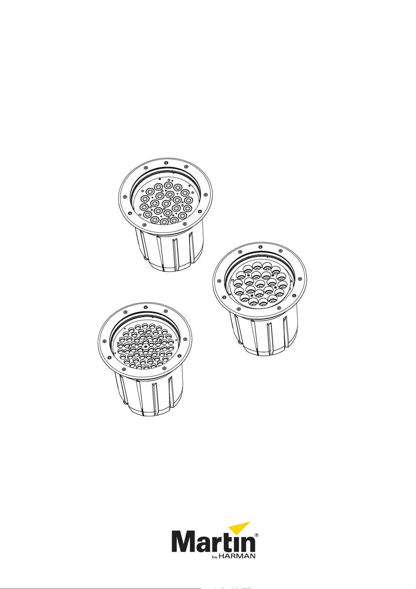
Inground 400 Series
User Manual
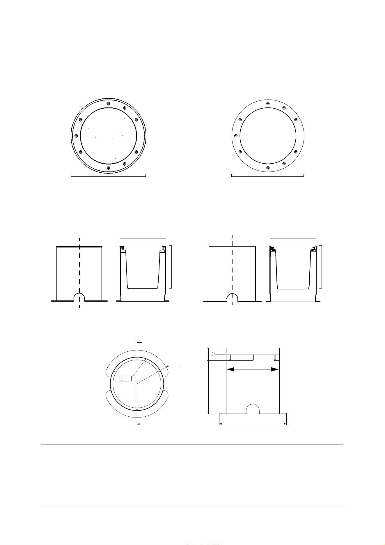
Dimensions
All dimensions are in millimeters
5
$
$
6(&7,21$$
Beveled top ring
With flush top ring
Installation sleeve only
Ø326
A
A
Section A-A
A
A
Section A-A
Fixture in installation sleeve
Ø340 Ø329
315 315
Ø329Ø340
Top ring
Flush top ring
With beveled top ring
Information subject to change without notice. HARMAN Professional Denmark ApS disclaims liability for any injury, damage, direct or indirect loss,
consequential or economic loss or any other loss occasioned by the use of, inability to use or reliance on the information contained in this document.
©2004-2017 HARMAN Professional Denmark ApS. All rights reserved. Martin® is a trademark of HARMAN Professional Denmark ApS registered in the
United States and/or other countries. Features, specifications and appearance are subject to change without notice.
HARMAN Professional Denmark ApS - Olof Palmes Allé 18 - 8200 Aarhus N - Denmark
www.martin.com
Inground 400 Series User Manual: P/N 5081891 Rev. E
Safety Information 3
Safety Information
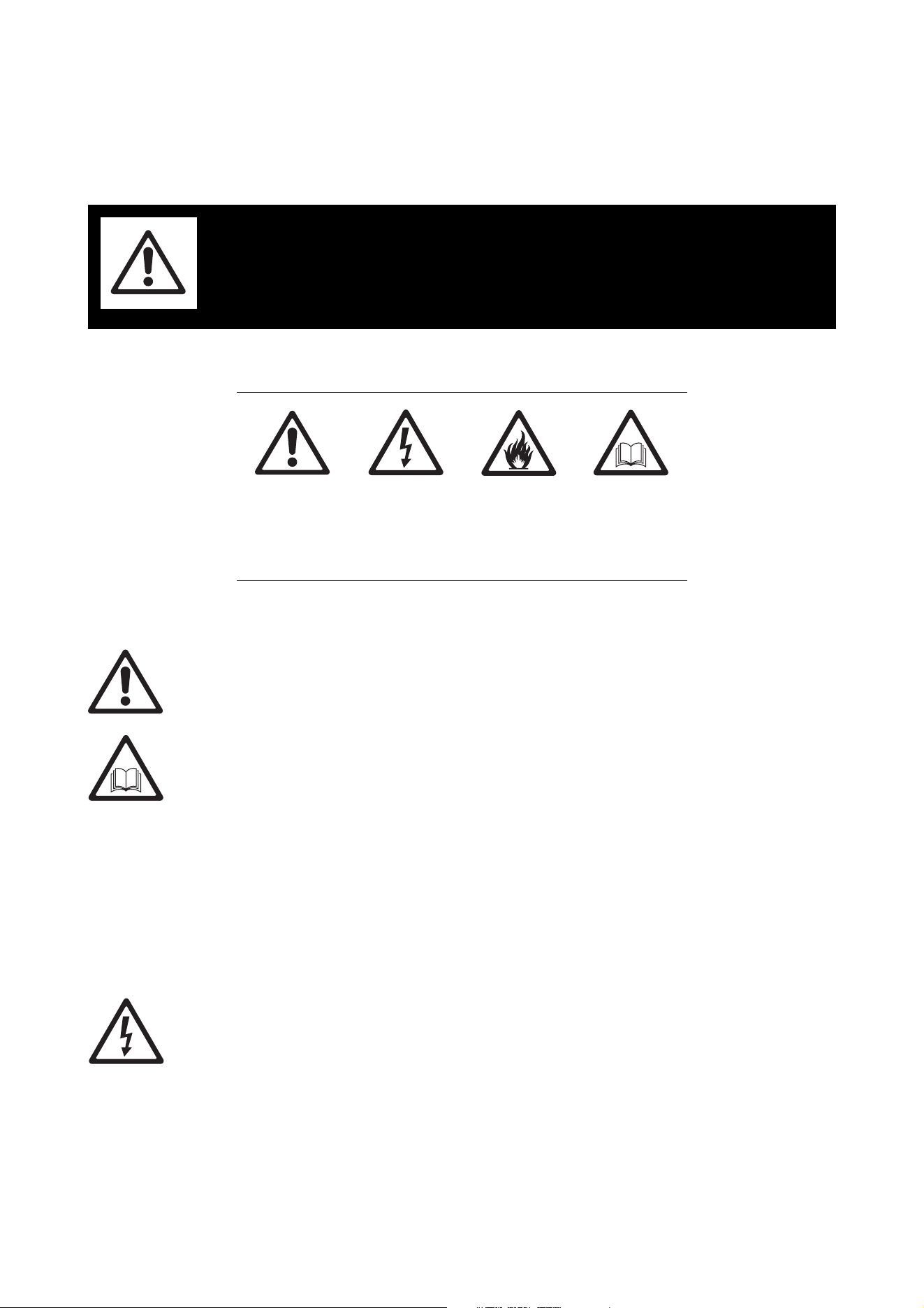
The following symbols are used to identify important safety information on the product and in this manual:
This product is for professional use only and must be installed by a qualified technician. It is not for
household use. It presents risks of injury or death due to fire hazards, electric shock and falls. It produces a
powerful, concentrated beam of light that can create a fire hazard or a risk of eye injury if the safety
precautions in this user manual are not followed.
Risk Group 1 (low risk) product according to EN 62471 on condition that the diffuser lens/sheet that the
fixture is supplied with is not removed from the fixture.
Install, operate and service Martin® products only as directed in their user manuals, or you may create a
safety hazard or cause damage that is not covered by product warranties. Follow the safety precautions
listed below and observe all warnings in this manual and printed on the product. Before using this manual,
please make sure that you have the latest revision of the manual. You can download the latest revisions of
all the product’s user documentation from the product’s Tech Docs / Product Support page at
www.martin.com.
If you have any questions or if you are in any doubt about how to install, operate or service this product
correctly and safely, please contact your Martin® supplier or call the Martin® 24-hour service hotline on +45
8740 0000, or in the USA on 1-888-tech-180.
Respect all locally applicable laws, codes and regulations when installing, operating or servicing the fixture.
Refer any operation not described in this manual to a qualified technician.
PROTECTION FROM ELECTRIC SHOCK
• Shut down power to the entire installation at the main power distribution board and lock out power (by
removing the fuse for example) before carrying out any installation or maintenance work.
• Disconnect the fixture from AC power before removing or installing any cover or part and when not in use.
• Connect the fixture electrically to ground (earth).
• Use only a source of AC power that complies with local building and electrical codes and has both
overload and ground-fault (earth-fault) protection.
• Connect the fixture to AC power using the supplied power cable only.
• If the external power cable of the fixture becomes damaged, you must replace the complete fixture.
WARNING!
Read the safety precautions in this section before
installing, powering, operating or servicing this
product.
WARNING!
Safety hazard.
Risk of severe
injury or death.
WARNING!
Hazardous
voltage. Risk of
lethal or severe
electric shock.
WARNING!
Fire hazard.
WARNING!
Refer to user
manual.
4 Inground 400 range user manual
• Connect the fixture’s cable tails to AC power and data circuits inside junction boxes that are rated IP67
minimum. Fill junction boxes with two-component potting compound to protect connections from water
and humidity.
• Before using the fixture, check that all power distribution equipment and cables are in perfect condition,
are rated for the current requirements of all connected devices, are protected to IP67 or higher and are of
suitable type for the location (including water, pollution, temperature and UV resistance).
• Isolate the fixture from power immediately if any cable, seal, cover or other component is damaged,
cracked or deformed. Do not reapply power until repairs have been completed.
• Do not expose any part of the fixture to a high-pressure water jet.
• Do not immerse the fixture in water or any other fluid, or install it in a location where flooding may occur.
• Refer any service operation not described in this manual to an authorized Martin® Service partner.
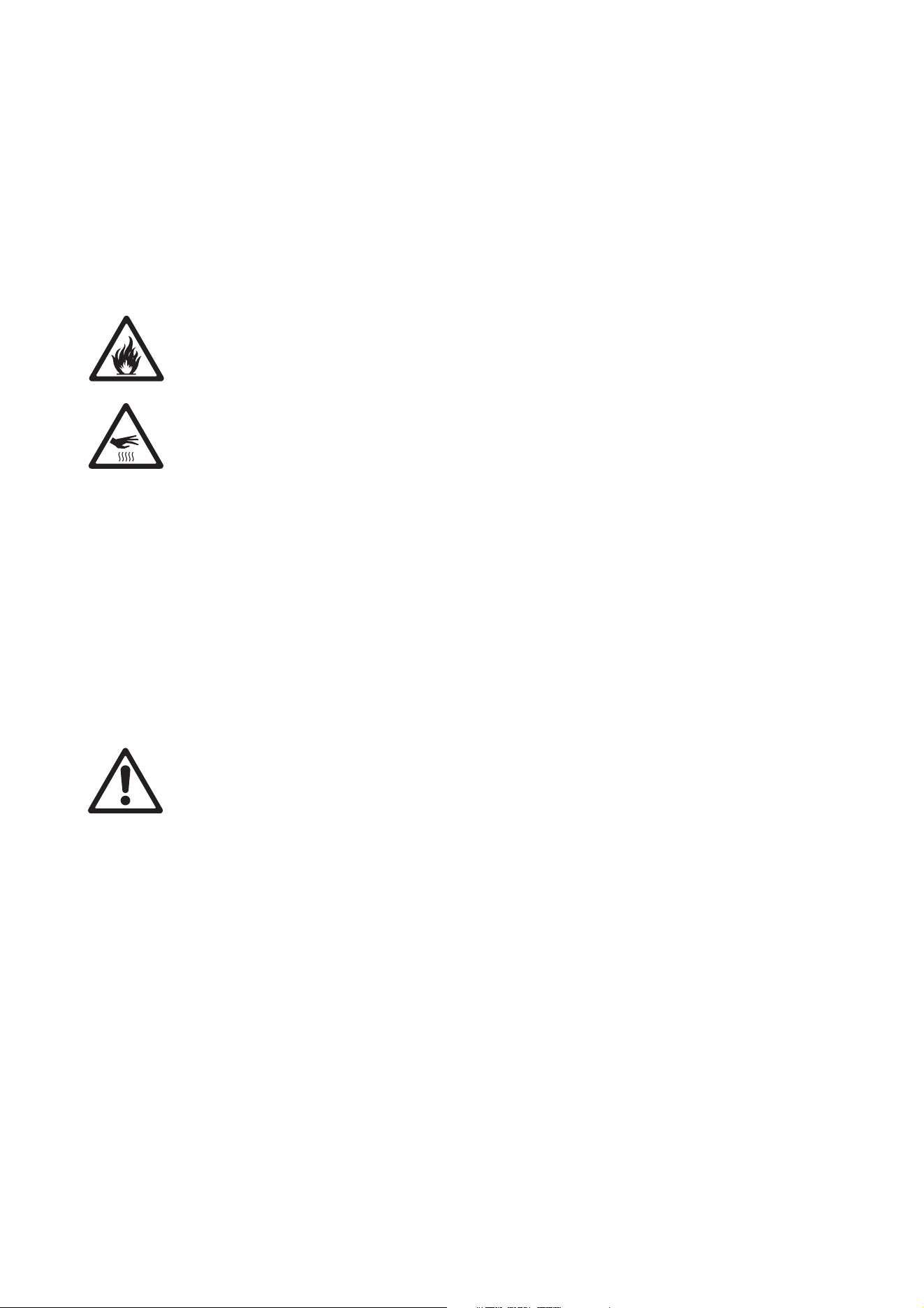
PROTECTION FROM BURNS AND FIRE
• Do not operate the fixture if the ambient temperature (Ta) exceeds 45° C (113° F).
• The exterior of the fixture becomes hot, up to 90° C (194° F) during normal operation. Ensure that
accidental physical contact with a hot fixture is impossible.
• Allow the fixture to cool for 20 minutes before cleaning or handling.
• Do not illuminate surfaces less than 0.2 m (8 in.) from the top surface of the fixture.
• Keep flammable materials well away from the fixture.
• Do not modify the fixture in any way not described in this manual or install other than genuine Martin®
parts. Do not stick filters, masks or other materials directly onto LEDs or onto the top glass. Use only
Martin®-approved optical configurations to mask or modify the light beam.
• Install the fixture:
- In an installation sleeve from Martin® or in a similar recess. There must be free airflow in the sleeve or
recess.
- Outdoors or in a well-ventilated area.
- At least 1 meter (40 inches) away from any combustible materials.
• Ensure that:
- The top glass is free of litter, leaves, dirt and anything else that could reflect heat back into the fixture.
- The installation sleeve is free of anything that could prevent free airflow around the fixture.
- Vehicles or other potential fire risks cannot be positioned over or near the fixture. This is particularly
important in situations where a vehicle (for example) may be left unattended over or near a fixture that
is not switched on at the time, but where the fixture may be switched on later.
PROTECTION FROM INJURY
• Do not operate the fixture without its diffuser lens/sheet installed, or you may create a risk of eye injury.
• Do not look at the fixture with magnifiers or similar optical instruments that may concentrate the light
output.
• Install the fixture:
- In an area where accidental contact with the top glass is unlikely, since the fixture becomes hot during
normal operation.
- With an anti-skid top glass in pedestrian traffic areas (an anti-skid top glass with an engraved design is
one of the configuration options available when ordering).
• Ensure that no fixtures or empty installation sleeves create a hazard that might result in falls or injuries. To
avoid accidents during installation or service, restrict access to the site and place both warning notices
and barriers around all work areas until work is completed and the site is safe.
• Fasten Martin® temporary installation lids into the tops of installation sleeves to protect pedestrians from
injury until fixtures are installed in the sleeves. Restrict access so that it is impossible to drive a vehicle or
position a heavy object over an installation lid.
• The insulation between the low voltage supply and the DMX cable is basic insulation only.

Contents
Dimensions . . . . . . . . . . . . . . . . . . . . . . . . . . . . . . . . . . . . . . . . . . . . . . . . . . . . . . . . . . . . . . . . . . . . . . . . 2
Safety Information. . . . . . . . . . . . . . . . . . . . . . . . . . . . . . . . . . . . . . . . . . . . . . . . . . . . . . . . . . . . . . . . . . 3
Introduction . . . . . . . . . . . . . . . . . . . . . . . . . . . . . . . . . . . . . . . . . . . . . . . . . . . . . . . . . . . . . . . . . . . . . . . . 6
Using for the first time . . . . . . . . . . . . . . . . . . . . . . . . . . . . . . . . . . . . . . . . . . . . . . . . . . . . . . . . . . . . . . . 7
Fixture overview . . . . . . . . . . . . . . . . . . . . . . . . . . . . . . . . . . . . . . . . . . . . . . . . . . . . . . . . . . . . . . . . . . . 8
Physical installation . . . . . . . . . . . . . . . . . . . . . . . . . . . . . . . . . . . . . . . . . . . . . . . . . . . . . . . . . . . . . . . . 9
General guidelines. . . . . . . . . . . . . . . . . . . . . . . . . . . . . . . . . . . . . . . . . . . . . . . . . . . . . . . . . . . . . . . . . . 9
New installs . . . . . . . . . . . . . . . . . . . . . . . . . . . . . . . . . . . . . . . . . . . . . . . . . . . . . . . . . . . . . . . . . . . . . . 13
Retrofit installs: general . . . . . . . . . . . . . . . . . . . . . . . . . . . . . . . . . . . . . . . . . . . . . . . . . . . . . . . . . . . . . 15
Retrofit install with a complete new fixture. . . . . . . . . . . . . . . . . . . . . . . . . . . . . . . . . . . . . . . . . . . . . . . 17
Retrofit install re-using existing parts. . . . . . . . . . . . . . . . . . . . . . . . . . . . . . . . . . . . . . . . . . . . . . . . . . . 19
Power and data cable layout. . . . . . . . . . . . . . . . . . . . . . . . . . . . . . . . . . . . . . . . . . . . . . . . . . . . . . . 22
AC power . . . . . . . . . . . . . . . . . . . . . . . . . . . . . . . . . . . . . . . . . . . . . . . . . . . . . . . . . . . . . . . . . . . . . . . . . 23
Connecting to power . . . . . . . . . . . . . . . . . . . . . . . . . . . . . . . . . . . . . . . . . . . . . . . . . . . . . . . . . . . . . . . 23
DMX-RDM data . . . . . . . . . . . . . . . . . . . . . . . . . . . . . . . . . . . . . . . . . . . . . . . . . . . . . . . . . . . . . . . . . . . 25
Connecting the data link . . . . . . . . . . . . . . . . . . . . . . . . . . . . . . . . . . . . . . . . . . . . . . . . . . . . . . . . . . . . 25
Fixture setup . . . . . . . . . . . . . . . . . . . . . . . . . . . . . . . . . . . . . . . . . . . . . . . . . . . . . . . . . . . . . . . . . . . . . . 27
Operation . . . . . . . . . . . . . . . . . . . . . . . . . . . . . . . . . . . . . . . . . . . . . . . . . . . . . . . . . . . . . . . . . . . . . . . . . 28
Heat management . . . . . . . . . . . . . . . . . . . . . . . . . . . . . . . . . . . . . . . . . . . . . . . . . . . . . . . . . . . . . . . . . 28
DMX control . . . . . . . . . . . . . . . . . . . . . . . . . . . . . . . . . . . . . . . . . . . . . . . . . . . . . . . . . . . . . . . . . . . . . . 28
Setup via RDM. . . . . . . . . . . . . . . . . . . . . . . . . . . . . . . . . . . . . . . . . . . . . . . . . . . . . . . . . . . . . . . . . . . . 28
Service and maintenance. . . . . . . . . . . . . . . . . . . . . . . . . . . . . . . . . . . . . . . . . . . . . . . . . . . . . . . . . . 29
Cleaning. . . . . . . . . . . . . . . . . . . . . . . . . . . . . . . . . . . . . . . . . . . . . . . . . . . . . . . . . . . . . . . . . . . . . . . . . 29
Optical configurations . . . . . . . . . . . . . . . . . . . . . . . . . . . . . . . . . . . . . . . . . . . . . . . . . . . . . . . . . . . . . . 30
Status indicator . . . . . . . . . . . . . . . . . . . . . . . . . . . . . . . . . . . . . . . . . . . . . . . . . . . . . . . . . . . . . . . . . . . 30
Updating fixture software . . . . . . . . . . . . . . . . . . . . . . . . . . . . . . . . . . . . . . . . . . . . . . . . . . . . . . . . . . . . 30
DMX protocols . . . . . . . . . . . . . . . . . . . . . . . . . . . . . . . . . . . . . . . . . . . . . . . . . . . . . . . . . . . . . . . . . . . . 31
Inground 400, Inground 410 . . . . . . . . . . . . . . . . . . . . . . . . . . . . . . . . . . . . . . . . . . . . . . . . . . . . . . . . . 31
Inground 420 . . . . . . . . . . . . . . . . . . . . . . . . . . . . . . . . . . . . . . . . . . . . . . . . . . . . . . . . . . . . . . . . . . . . . 32
Troubleshooting. . . . . . . . . . . . . . . . . . . . . . . . . . . . . . . . . . . . . . . . . . . . . . . . . . . . . . . . . . . . . . . . . . . 33
Specifications . . . . . . . . . . . . . . . . . . . . . . . . . . . . . . . . . . . . . . . . . . . . . . . . . . . . . . . . . . . . . . . . . . . . . 34

6 Inground 400 range user manual
Introduction
Thank you for selecting a product from the Inground 400 range of LED-based uplight fixtures from Martin
Professional. The Exterior Inground 400 range is a range of uncomplicated, easy-to-use color-changing
LED luminaires. Inground 400 fixtures combine the benefits of dynamic light and discreet installation. The
recessed housing can be made to fit any type of surface with a top ring (trim ring) available in beveled and
flush-mount versions. The range of beam angle options available includes asymmetric and directional
models.
Configurations
When ordering products from the Inground 400 range, you can configure them to match your requirements
by selecting from the following options (see "Ordering Information" on page 36):
Series
• Inground 400
Optimized for narrow beam angle configurations
56 x R, G, B and W LEDs
• Inground 410
Optimized for evenness of color mixing
22 x quadcolor LEDs
• Inground 420
Optimized for color temperature control
56 x cool white and warm white LEDs
Power cable
• EU cable
• US cable
Glare Shield
• No glare shield (Inground 410 only)
• Glare shield, 22 LEDs – for Inground 410
• Glare shield, 56 LEDs – standard (and required) for Inground 400 and 420
Diffuser
• No diffuser (the fixture can be ordered without a diffuser, but a diffuser must always be installed in the
fixture during use)
•Narrow
• Medium
•Wide
• 8° Directional and asymmetric
• 20° Directional
• Asymmetric
Top glass
• Standard
• Anti-skid
• No top glass (the fixture can be ordered without a top glass, but a top glass must always be installed in
the fixture during use)
Top ring
•Beveled
•Flush
All models feature:
• Auto-sensing power supply unit with 100 - 277 V nominal, 50/60 Hz operating range
• DMX 512 control
• Remote configuration and addressing over the DMX data link via RDM (Remote Device Management).
For the latest light output measurements, firmware updates, documentation, product specifications and
other information about this and all Martin Professional products, please visit the Martin® website at
http://www.martin.com

Introduction 7
If you have any comments or suggestions regarding this user manual, please e-mail us at
service@martin.dk.
Using for the first time
Before applying power to the fixture:
• Carefully review “Safety Information” on page 3.
• Check that the local AC power voltage is within the range listed on the fixture’s serial number label.
• Install the fixture as described in this user manual.
8 Inground 400 range user manual
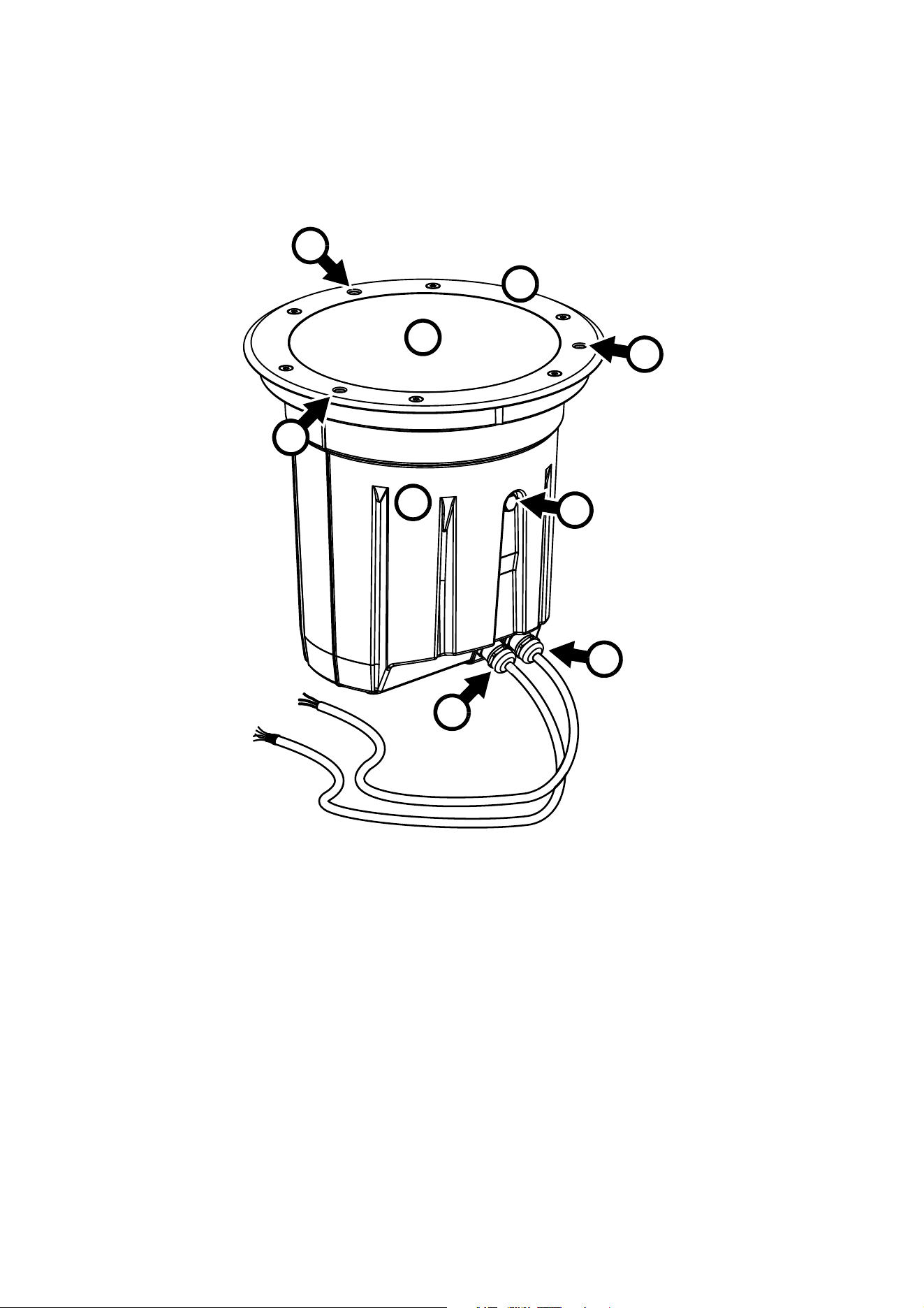
Fixture overview
B
C
C
C
A
F
E
G
A Top glass
B Top ring (beveled ring shown)
C Holes for installation bolts
D Fixture housing
E Gore-Tex pressure relief valve
F Data cable entry
G Power cable entry
D
Figure 1: Fixture overview
Physical installation 9
Physical installation
General guidelines
Warning! Read "Safety Information" on page 3 before installing a fixture in the Inground 400 range.
Warning! The safety and suitability of the installation location and electrical installation is the
responsibility of the installer. All local safety regulations and legal requirements must be observed
when installing and connecting fixtures. Installation must be carried out by qualified professionals
only.
Warning! Contact your Martin® supplier for assistance if you have any questions about how to
install this product safely.
Important! If the product is not installed as described in this user manual, performance may be
unsatisfactory and damage may be caused that is not covered by the product warranty. Martin® will
gladly provide assistance in planning and carrying out installation.
The installation location and method must be carefully chosen in order to avoid heat and moisture build-up
and to ensure satisfactory performance over the product’s lifetime.
Please first read the general guidelines below, then use the instructions later in this chapter to guide you
while you install a fixture.
Installation sleeve
Warning! Empty installation sleeves present a hazard to any person walking at the installation site.
Install a temporary lid as described below and/or prevent pedestrian access to the site until fixtures
have been installed in all sleeves. Prevent vehicle access to the site until fixtures have been
installed in all sleeves.
The fixture is designed to be installed in an installation sleeve or similar construction. We recommend using
the rugged installation sleeve with a drive-over rating of 40 000 N (8800 lbs.) designed specifically for the
Inground 400 range that is available from Martin®. The sleeve must be ordered separately.
In existing installations where Martin® Inground 200 fixtures are being removed and replaced with ‘Retrofit’
fixtures* from the Inground 400 range, existing Martin® installation sleeves can be re-used.
Customers can supply their own installation sleeves or similar constructions, but Martin® cannot take any
responsibility for damage or loss of performance that occurs as a result of installing Inground 400 fixtures in
any construction other than a Martin® sleeve.
*See "Ordering Information" on page 36.
Installation lids for installation sleeves
Warning! The temporary installation lids available from Martin® can support the weight of a
pedestrian, but they are not designed to support the weight of a vehicle. Prevent vehicle access to
the site until fixtures have been installed in all sleeves.
If an installation sleeve is installed in the ground but stands empty until an Inground fixture is installed in it,
the open hole at the top of the sleeve can present a hazard to any person walking at the installation site.
Rainwater, dirt and debris can also collect in the sleeve, making installing the fixture difficult. To avoid these
problems, Martin® can supply temporary installation lids that fit into the tops of installation sleeves and
cover the hole in the sleeve temporarily while waiting for fixtures to be installed or if fixtures are removed for
service.
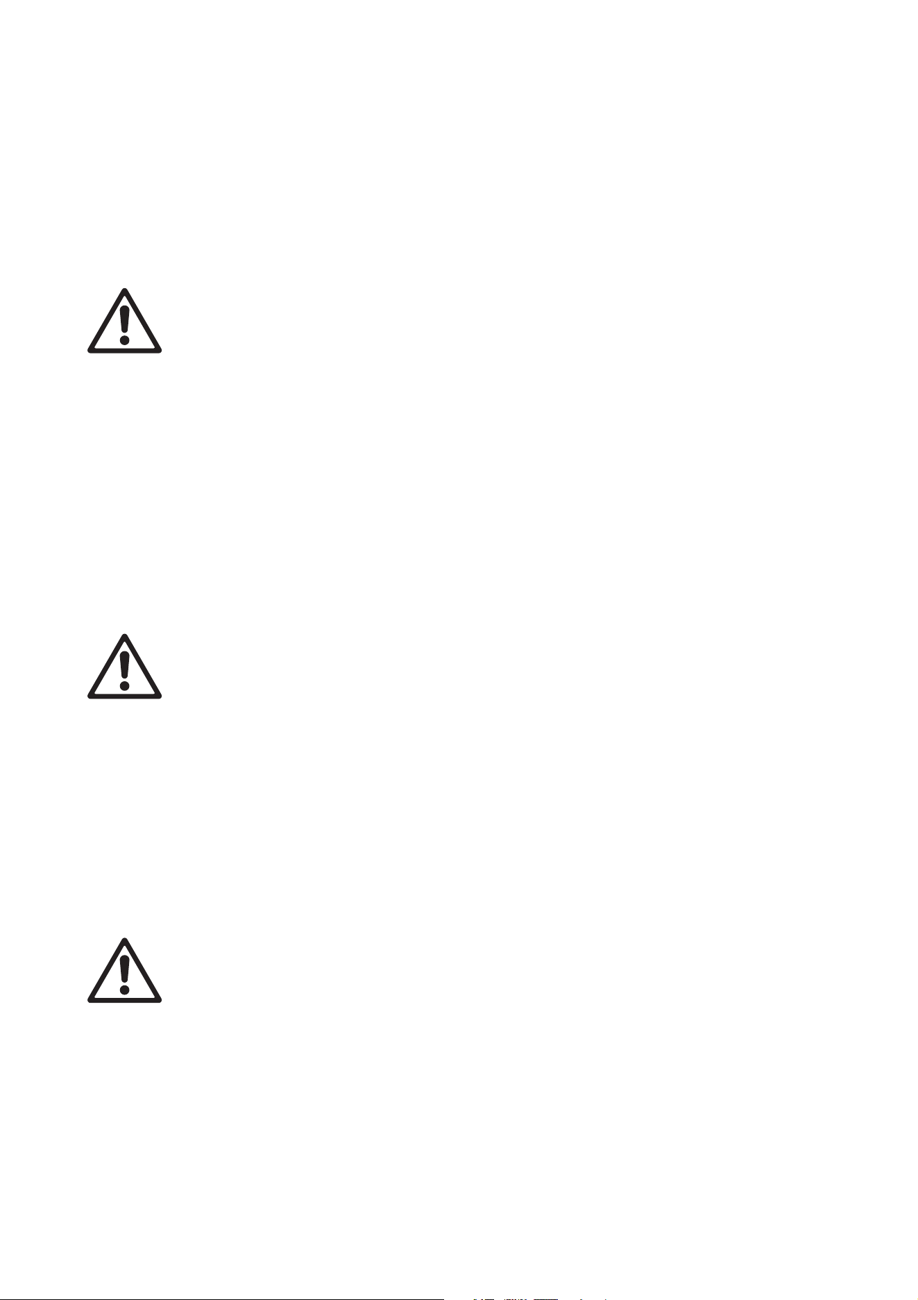
See Figure 2. Two types of lid are available: lid A is designed for flush top ring installations and lid B is
designed for beveled top ring installations. The lids are designed to be fastened into the top of installation
sleeves using three M6 bolts.
We recommend that you install lids during paving or tarmac work around installation sleeves. This will avoid
damage to sleeves and prevent surfacing material falling into the sleeve. Finish tarmac or paving at the
10 Inground 400 range user manual
same level as the top of the installation lid. See Figure 2. The different thicknesses of the two installation lids
allow for the different thicknesses of the flush mount and beveled top rings available for the Inground 400
range.
Avoiding humidity and condensation
Important! Do not open the top glass when installing the fixture.
The fixture is supplied as a factory-sealed, de-humidified unit. Opening the fixture will allow moisture to
enter. Install the fixture in its installation sleeve using three bolts in the holes that pass through the top ring.
Do not remove the top glass.
There is an exception to the above: if you are carrying out a retrofit installation and re-using the top glass
and top ring from an existing fixture, your new fixture will be supplied open, with no top glass. In this case,
follow the instructions on avoiding humidity given in “Retrofit install re-using existing parts” on page 19.
Avoiding corrosion
Do not scratch or damage the outer surface of the fixture. The housing is coated at the factory to protect it
against corrosion, but if the coating is damaged this protection may be lost, invalidating the product warranty
if corrosion should occur.
Cooling
The Inground 400 range regulates light output to control its internal temperature and ensure that all
components operate within their thermal specification.
The fixture is cooled by the convection of air in the installation sleeve or recess in which it is installed and
conduction to the surrounding material in the installation site. Do not install the sleeve in material with
insulating properties.
Water resistance and drainage
The fixture has an ingress protection rating of IP67. This means that it can withstand immersion for 30
minutes and low-pressure water jets. However, it is not designed to withstand constant immersion, so take
the following into account when planning the installation site:
• The base of Inground 400 fixtures must not be submerged in water other than for very short periods.
• Effective drainage that can prevent any buildup of water in the installation sleeve is absolutely essential
and must be provided and tested before the fixture is installed. It must be possible for water from rain,
melting snow, flooding or other sources to drain out of the installation sleeve at least as fast as it can enter
it. If water is present in the installation well for extended periods, the product warranty will be invalidated.
• If in doubt about a particular site, consult a geotechnical engineer.
Figure 2: Installation lids for flush mount and beveled installation types
A
B
Physical installation 11
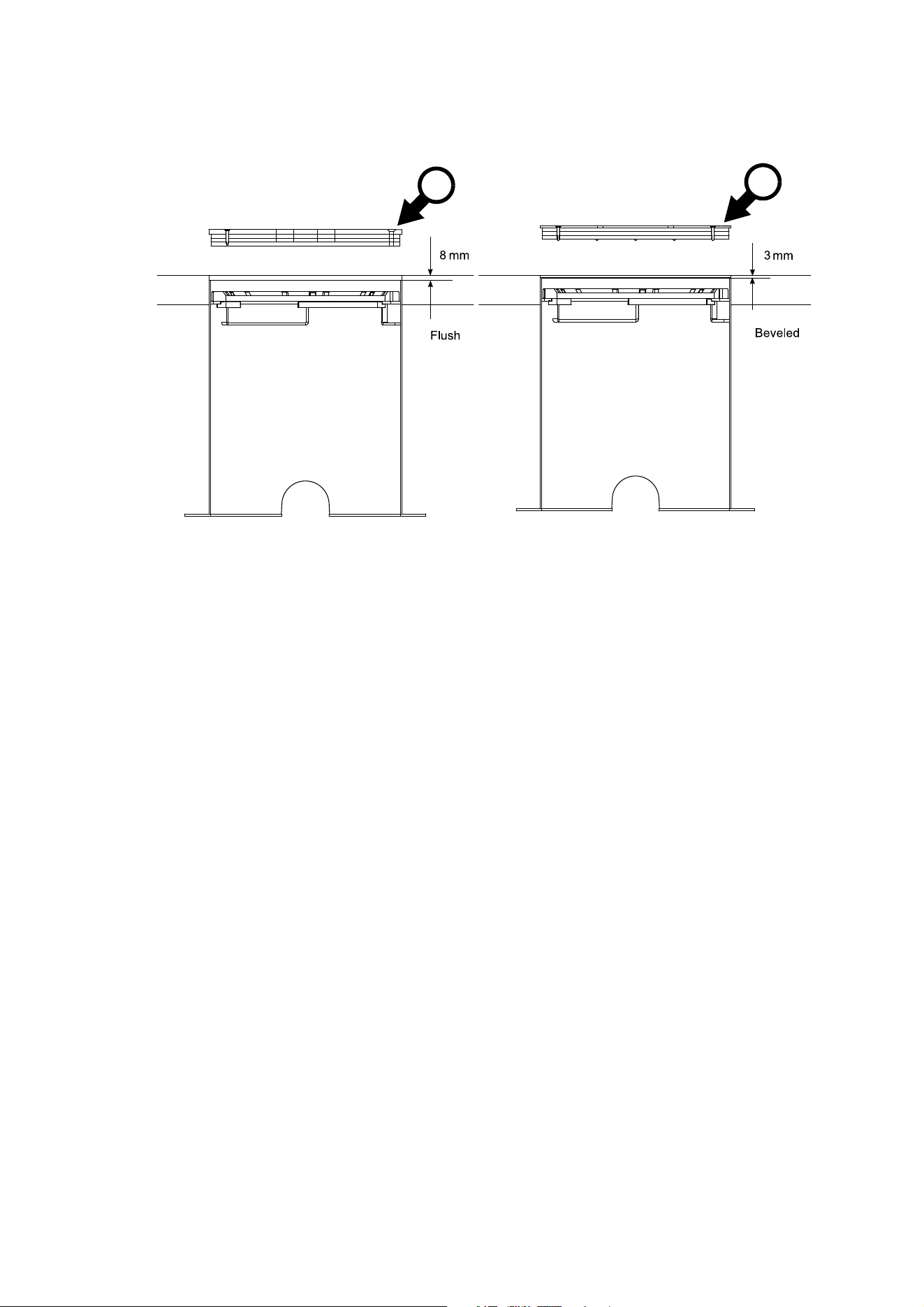
• See Figure 3. To minimize the risk of flooding or waterlogging, install the fixture in a location which is
above the level of the surrounding area and/or make sure that drainage conditions are adequate.
Pressure equalization valves
A valve with a Gore-tex membrane in the housing equalizes pressure by allowing air to pass through it when
the fixture heats up and cools down, but at the same time it acts as a barrier to water in liquid form. The
expulsion of warm air (with a slightly higher water vapor content) and intake of cool air (with a slightly lower
water vapor content) prevents humidity buildup over time, provided that the valve works correctly and that
the fixture is correctly sealed.
If the valve is underwater while the fixture cools down and its internal pressure falls, the valve will not be
able to let air enter the fixture. Water may then be sucked into the fixture past seals and even along cables.
Pressure equalization valves can also become blocked after an extended period of use if the micropores in
the membrane fill up with dirt particles. Valves cannot be cleaned and must be replaced if they become
blocked. Valve replacement intervals depend on the amount of dirt and dust in the installation location. We
recommend that you consult your Martin® supplier about possible inspection intervals. Replacement valves
must be installed by Martin® Service or its authorized agents.
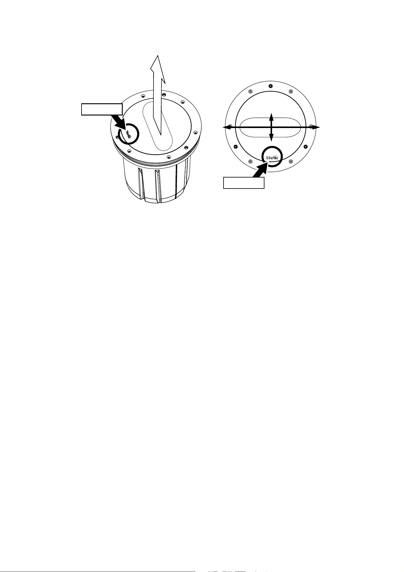
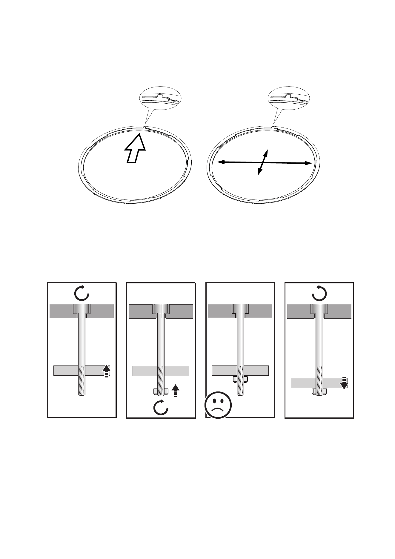
Directional fixture orientation
When you install a fixture that has a directional
filter, you must orient it so that its light output points
in the intended direction.
See Figure 4. Note the position of the Martin® logo
on the top glass. Directional filters are installed at
the factory so that the light output points away from
the Martin® logo.
Figure 3: Avoiding flooding
Direction of
light output
Figure 4: Light output with directional filters
Martin® logo
12 Inground 400 range user manual
Asymmetric beam angle orientation
When you install a fixture that has an asymmetric beam angle lens, you must orient it so that the wide and
narrow axes in the light output are lined up as intended.
See Figure 5. Note the position of the Martin® logo on the top glass. Asymmetric lenses are installed at the
factory so that the wide-angled light output comes from the sides of the fixture and the narrow-angled light
output comes from the front and back of the fixture when the Martin® logo is at the front or back of the
fixture.
Before you begin installing
Important! The fixture is sealed and vacuum tested at the factory to ensure that it is protected from
humidity. Do not open the fixture, as this will allow humidity to enter. If you need to remove the top
glass at any time, please contact Martin® Service for assistance and advice on eliminating humidity.
Before you install an Inground 400 range fixture, read "Safety Information" on page 3 and read this Physical
Installation chapter from the beginning to familiarize yourself with general guidelines and installation
hardware.
The procedure for installing a fixture from the Inground 400 range varies depending on whether the
installation is:
•a new install with a new installation sleeve, or
•a retrofit install, where a new Inground 400 fixture replaces a Martin® Inground 200 fixture in an existing
installation sleeve.
Instructions for these two different types of installation are given in separate sections in the rest of this
chapter.
Wide
axis
Figure 5: Orientation of asymmetric beam angle
Martin® logo
Martin® logo
Narrow
axis
Physical installation 13
New installs
A ‘new install’ means installing a new Inground 400 fixture in a new Inground 400 installation sleeve. To
carry out a new install, follow the procedure below.
Installing an installation sleeve
1. Make sure that the base of the installation well can bear the weight of the installation sleeve and fixture
with the maximum required load without sinking. In a drive-over installation, this means that it should
withstand a load of up to 40 000 N (8800 lbs.) plus fixture and sleeve.
2. Make sure that there is adequate drainage from the installation well as described earlier in this chapter.
3. See Figure 2 on page 10. We recommend that the top of the installation sleeve sits:
• 8 mm below terrain in installations with flush-mount top rings, or
• 3 mm below terrain in installations with beveled mount top rings.
4. Prepare conduit, cabling and junction boxes so that the fixture can be connected to AC power and to
data circuits.
Make sure that all items are of a suitable type for their purpose and the environment, and that they have
adequate IP ratings. Make sure that cables will not open into damp locations, otherwise expansion and
contraction due to heat may suck moisture along cables into fixtures and cause condensation. Do not
bury the power supply cable or data cable directly in the ground. Install all cables in conduit that is
suitable for the installation environment. Make all connections inside junction boxes that are totally
sealed against the entry of water.
5. Fix the installation sleeve in its well in whatever orientation is easiest (for cabling, for example).
6. If a fixture with a directional or asymmetric beam will be installed in the sleeve, first see “Directional
fixture orientation” and “Asymmetric beam angle orientation” earlier in this chapter.
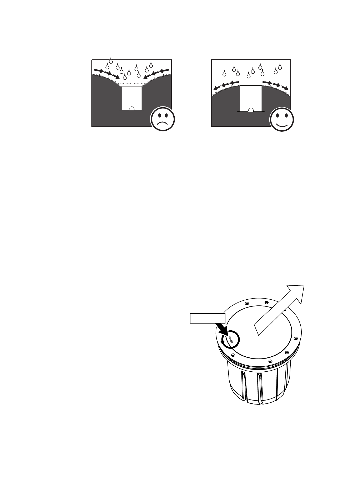
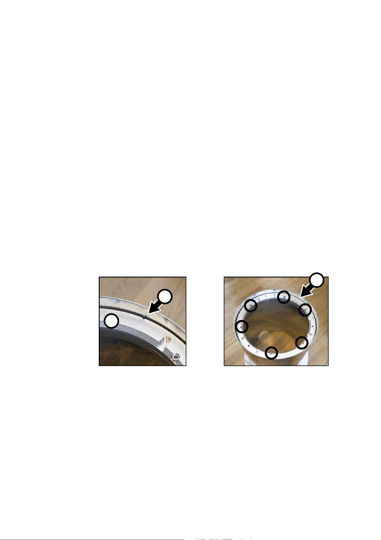
7. See Figure 6. There is an alignment mark A in the mounting ring B. Loosen the six screws shown in
circles in the mounting ring. This loosens the clamps underneath the mounting ring and lets you rotate
the mounting ring to adjust the position of the alignment mark.
8. Rotate the mounting ring B until the alignment mark A is:
• pointing directly towards the surface to be illuminated if a directional beam fixture will be installed in
the sleeve, or
• pointing in the direction of the narrow beam angle (and therefore at 90° to the wide beam angle) if an
asymmetric beam fixture will be installed in the sleeve.
In both cases, the alignment mark must be on the opposite side of the sleeve from the side with the
Martin® logo on the fixture’s top glass.
9. Retighten the six screws to fasten the mounting ring in its correct orientation.
Figure 6: Orientation mark in mounting ring
A
B
A
14 Inground 400 range user manual
Installing a fixture
1. Make sure that AC power to the installation is shut down and cannot be applied (by removing a fuse, for
example).
2. Place the fixture next to the installation sleeve and connect it as described in the “AC power” and
“DMX-RDM data” chapters later in this manual.
3. Lower the fixture into the sleeve and
rotate it until you have aligned the
fixture correctly as described under
“Directional fixture orientation” and
“Asymmetric beam angle
orientation” earlier in this chapter,
using the Martin® logo for reference.
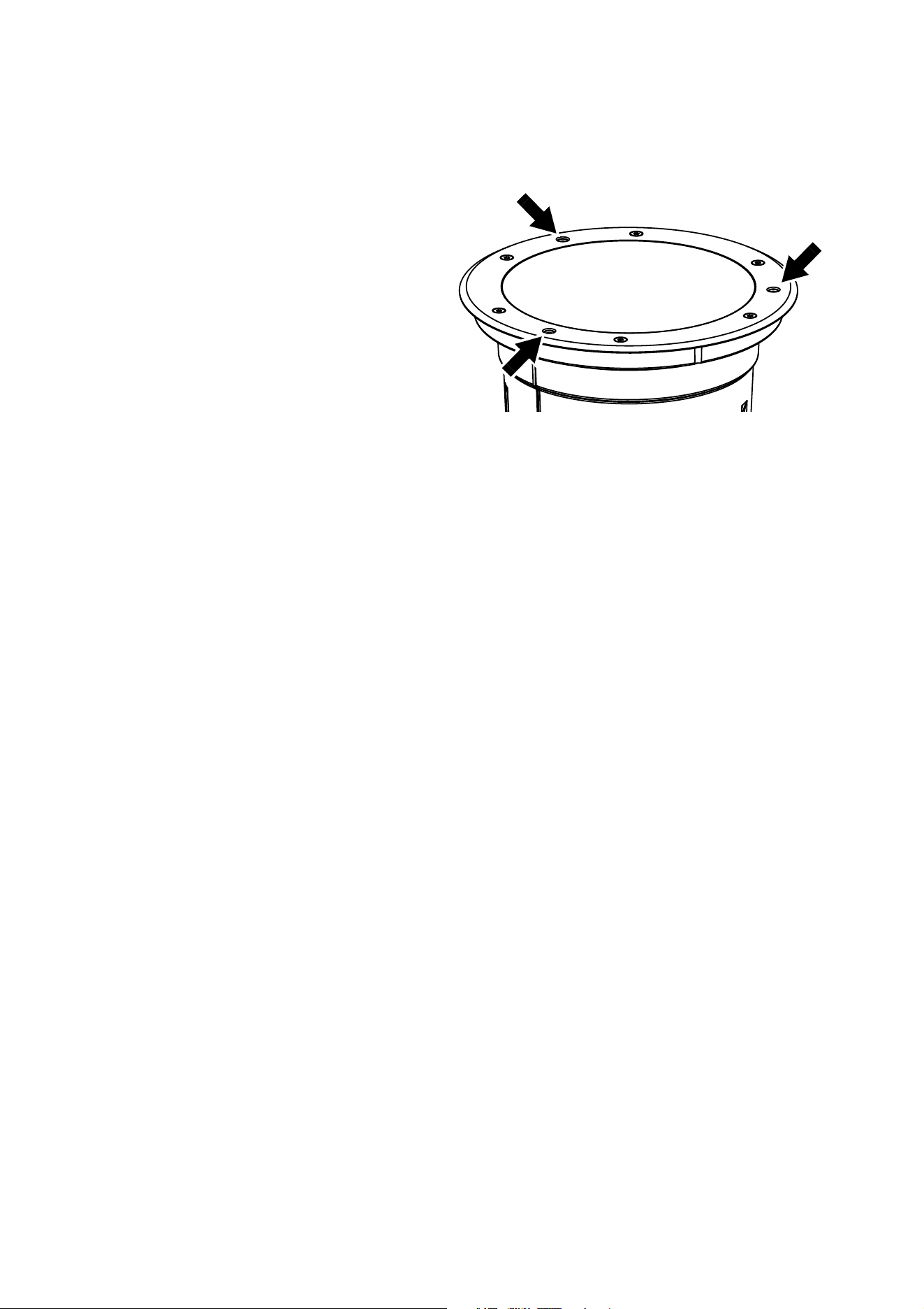
The three holes for fixture mounting
bolts (arrowed in Figure 7) in the top
ring of the fixture should line up with
the threaded holes in the mounting
ring in the installation sleeve (if
necessary, you can adjust the
mounting ring as described above).
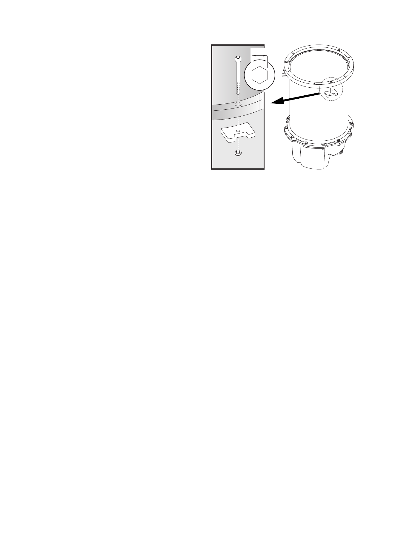
4. See Figure 7. Fasten the fixture into
the installation sleeve by passing the
three supplied M6 bolts through the
holes fixture’s top ring and fastening
them into the mounting ring in the sleeve. Use a torque driver and cross-tighten them to around 3 Nm.
Figure 7: Inground 400 mounting bolts
Physical installation 15
Retrofit installs: general
A retrofit install involves installing a new Inground 400 fixture into an existing Inground 200 installation
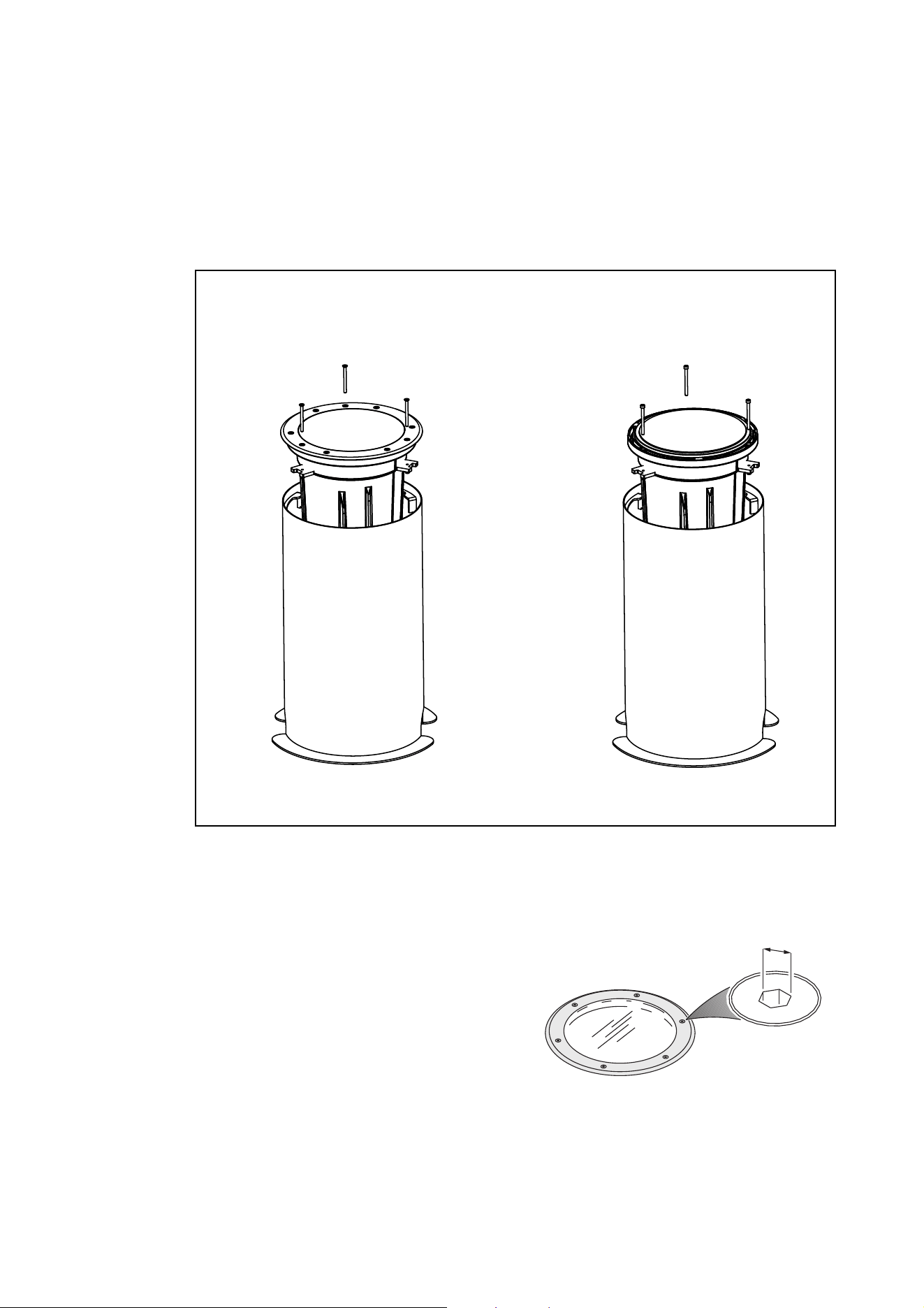
sleeve. See Figure 8. Retrofit installs fall into two types:
• Installing a complete new fixture
• Installing a new fixture re-using the top ring and top glass from the existing Inground 200 fixture.
To carry out a retrofit installation, follow the procedure below.
Removing the existing Inground 200 fixture
1. Make sure that AC power to the installation is shut
down and cannot be applied (by removing a fuse,
for example).
2. Check that the existing Inground 200 installation
sleeve meets weight-bearing and drainage
requirements.
3. See Figure 9. Remove the six screws from the
Inground 200’s top ring. If you are going to re-use
the top ring and top glass, keep these six screws
for re-use.
4. Lift the top glass off the Inground 200.
Figure 8: Two types of retrofit installation
Retrofit installation
re-using top glass and top ring
Retrofit installation
with complete new fixture
4mm
Figure 9: Inground 200 top ring screws
16 Inground 400 range user manual
5. See Figure 10. Loosen the three fixture
mounting bolts A to loosen the clamps C.
Rotate the Inground 200 in the installation
sleeve until the clamps C are clear of the
fins inside the installation sleeve, then lift
the Inground 200 out of the sleeve.
6. Disconnect the Inground 200 from power
and data. Check that conduit and cabling
are in perfect condition. Renew any items
that are not suitable for reuse.
7. Place the new Inground 400 fixture next
to the installation sleeve and connect it to
power and data as described in the “AC
power” and “DMX-RDM data” chapters
later in this manual.
8. If a fixture with a directional or
asymmetric beam will be installed in the
sleeve, first see “Directional fixture
orientation” and “Asymmetric beam angle
orientation” earlier in this chapter.
The rest of the installation procedure
depends on whether the you are installing a complete new Inground 400 fixture or a new Inground 400
fixture without top ring and top glass in the existing Inground 200 installation sleeve:
• If you are installing a complete new fixture, go straight to the next section.
• If you are installing a new fixture re-using the existing top ring and top glass from the Inground 200 fixture,
go to “Retrofit install re-using existing parts” on page 19.
5mm
A
B
D
C
Figure 10: Removing an Inground 200 from its
installation sleeve
Physical installation 17
Retrofit install with a complete new fixture
Important! There is no need to open the new fixture when you carry out a retrofit install with a complete new
Inground 400 fixture. Do not open the fixture, or you will allow humidity to enter.
You will need to use the three new stainless steel M6 x 70 fixture mounting bolts supplied with the new
fixture plus the original clamps and nuts (see Figure 10) from the Inground 200. Note that the three new
bolts are countersunk and slightly longer than the original bolts from the Inground 200.
You will need new IP67-rated junction boxes and potting compound for connections to AC power and data.
To install a complete new fixture in an existing Inground 200 installation sleeve:
1. Make sure that AC power to the installation is shut down and cannot be applied (by removing a fuse, for
example).
2. Place the fixture next to the installation sleeve and connect it as described in the “AC power” and
“DMX-RDM data” chapters later in this manual.
3. Apply a small amount of grease or anti-seize compound to the threads of the three new mounting bolts
to reduce galvanic corrosion.
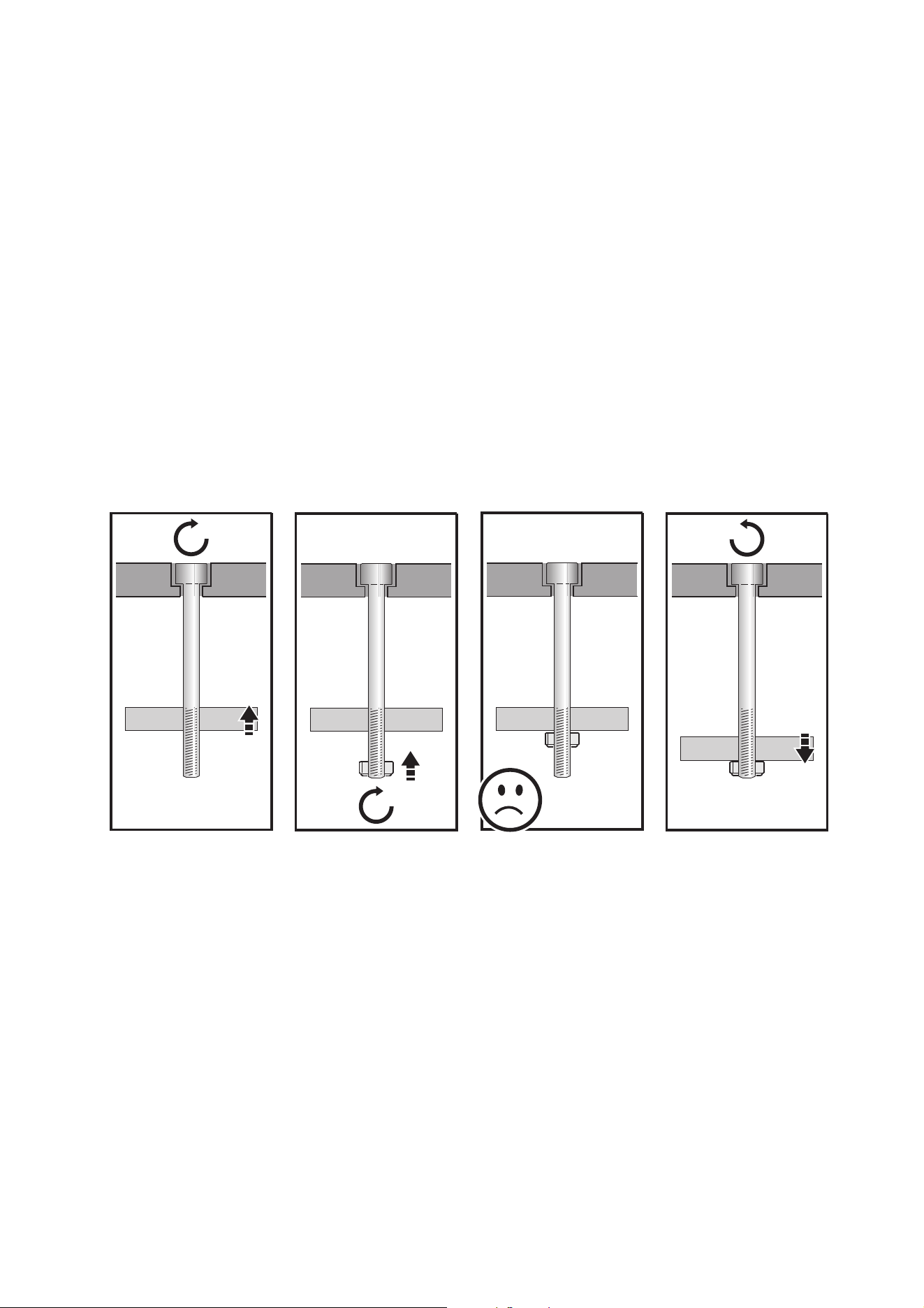
4. Prepare the mounting clamps for the Inground 400 fixture as described below (the illustrations show a
socket head cap bolt while the new bolts supplied are countersunk, but this does not affect the
procedure):
5. Rotate the fixture until it is oriented as closely as possible to the optimum angle as described under
“Directional fixture orientation” and “Asymmetric beam angle orientation” earlier in this chapter, using the
Martin® logo for reference.
If this angle is not close enough to the desired beam angle, please contact your Martin® supplier for
assistance. It only takes a minute or two to remove the top glass and adjust the diffuser or directional
turning film, but you must follow the correct procedure and install a new silica gel anti-humidity bag on
the side of the module inside the fixture. Your Martin® supplier or Martin® Service will be glad to help.
A
B
C
A
B
C
D
A
B
C
D
A
B
C
D
Pass each of the three
stainless steel
countersunk M6 x 70
bolts (A) through one of
the three holes in the top
ring (B) and screw the
bolt through a clamp block
(C).
Screw a self-locking nut
(D) onto the end of each
bolt until the nut is flush
with the end of the bolt.
Do not screw the nut any
further up the bolt.
Unscrew each bolt (A)
back up through the
clamp block (C) until the
retaining nut (D) touches
the clamp block.
Figure 11: Preparing mounting clamps
18 Inground 400 range user manual
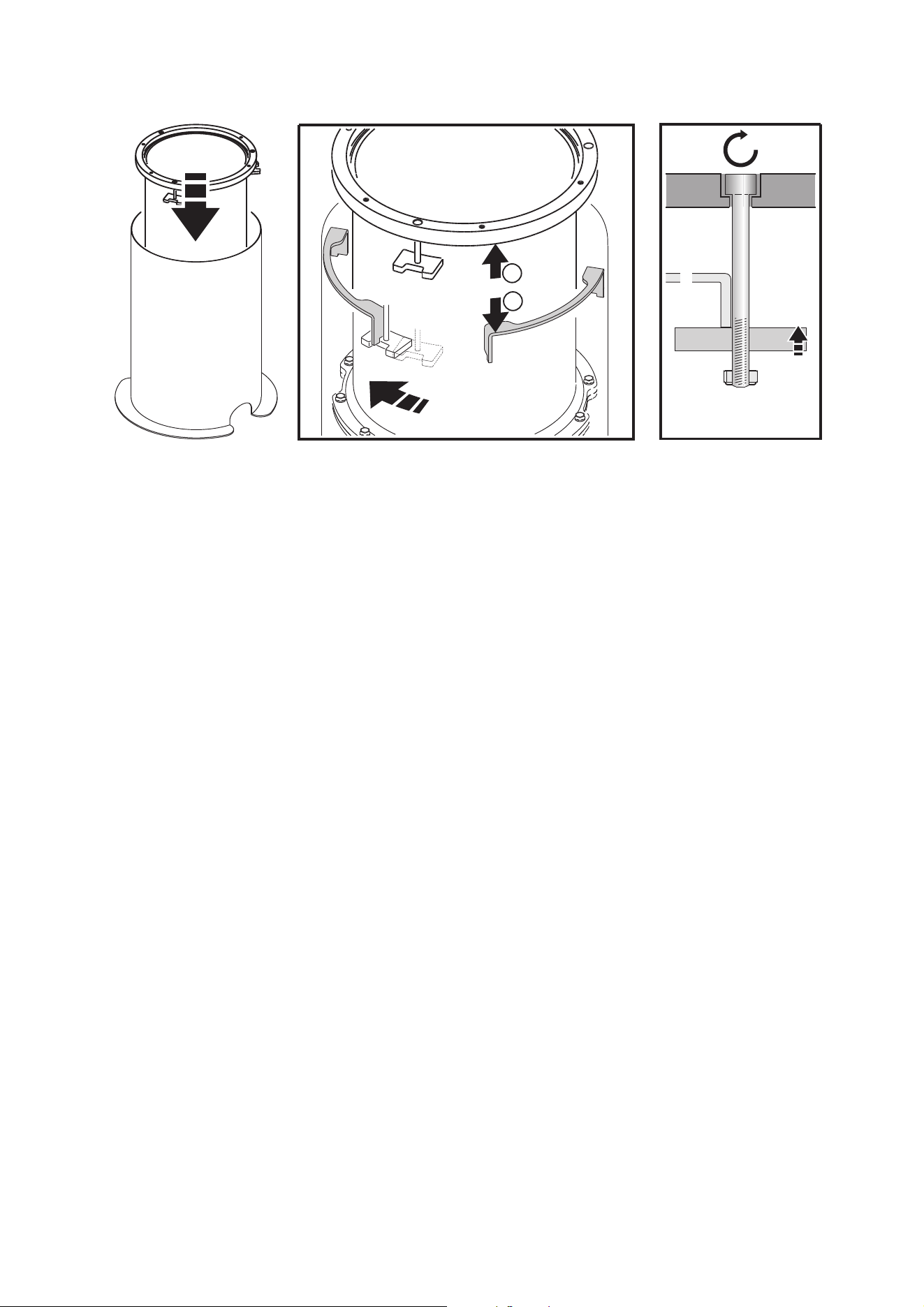
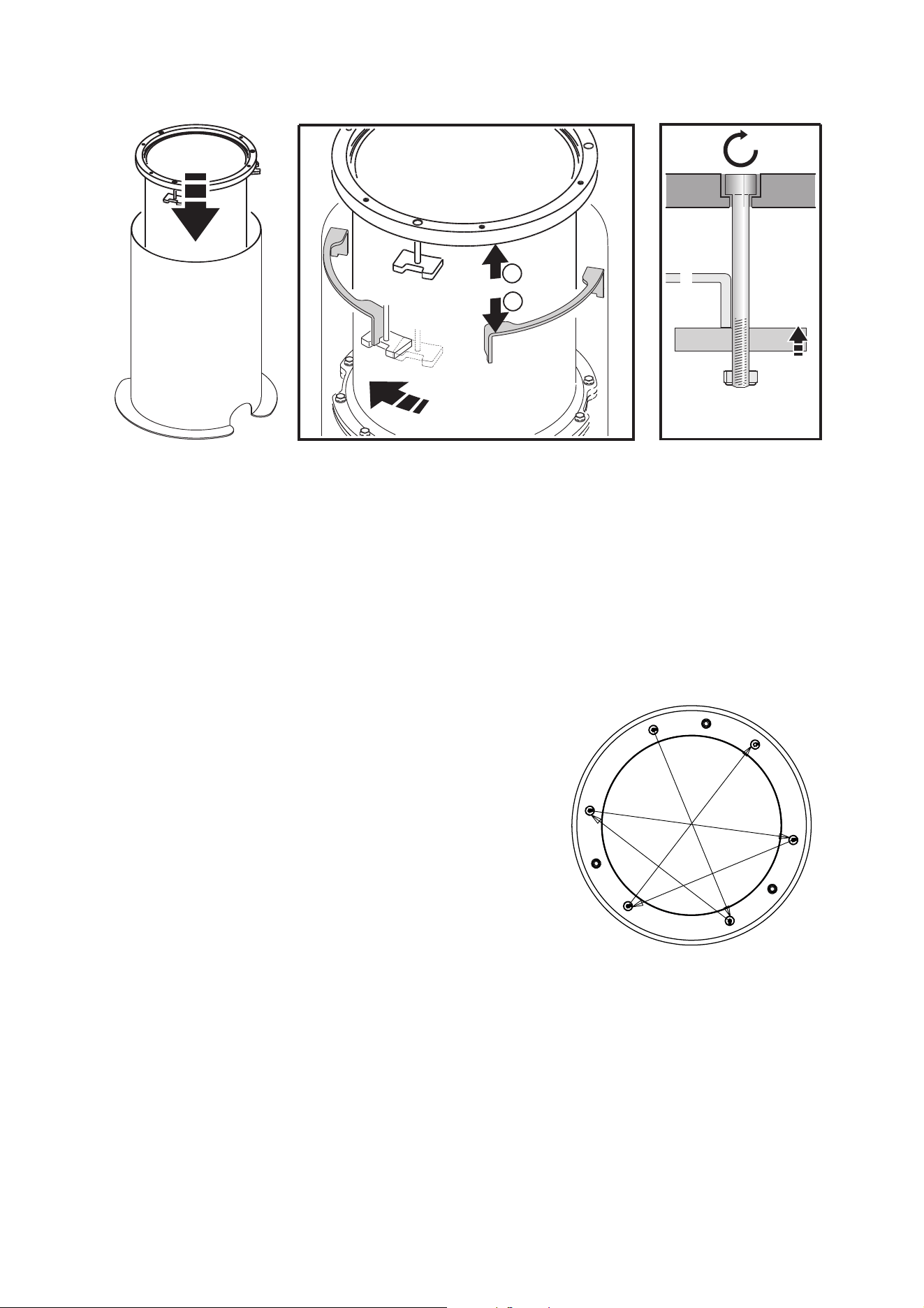
6. Clamp the fixture into the installation sleeve as shown below:
7. With directional and asymmetric beam angle fixtures, check that the orientation of the beam is correct
with reference to “Directional fixture orientation” on page 11 and “Asymmetric beam angle orientation”
on page 12. Adjust if necessary by rotating the fixture in the sleeve.
8. Finally, tighten the clamp bolts to around 3 Nm.
A
B
E
C
D
B
E
Tighten the three clamp
bolts (A) finger-tight only.
Holding the fixture by the
inside rim of the housing,
begin lowering it into its
sleeve.
As you lower the fixture, ensure that the clamp blocks
(C) pass between the fins in the sleeve so that the
outer rim (B) sits on the fins (E). Then rotate the
fixture so that the clamp blocks locate under the fins.
Figure 12: Retrofit installation, fastening fixture into installation sleeve
Physical installation 19
Retrofit install re-using existing parts
In this type of retrofit installation, an Inground 400 range fixture is supplied with no top glass or top ring so
that you can re-use the original top glass, top ring and fasteners from an existing Inground 200 installation.
You will need to re-use:
• the three stainless steel M6 x 70 fixture mounting bolts, clamps and nuts (see Figure 10 on page 15) that
were used to fasten the Inground 200 into the installation sleeve,
• the six M6 x 25 top ring screws (see Figure 9 on page 14)
• the original top ring and top glass from the Inground 200.
You will need new IP67-rated junction boxes and potting compound for connections to AC power and data.
Check that the top ring and top glass from the Inground 200 are in perfect condition. Replace any items that
are not fit for re-use. We recommend that you order a new top glass seal, but you can re-use the seal from
the Inground 200 if it is in perfect condition.
Martin® supplies silica gel anti-humidity bags for use with Inground 400 fixtures that have been opened.
One bag is supplied with each retrofit fixture that re-uses existing parts because these fixtures are supplied
open. As soon as you remove a silica gel from its sealed foil wrap it will begin to absorb humidity, so close
the fixture as soon as possible after you remove the silica gel bag from its wrap.
To install a new Inground 400 in an existing Inground 200 installation sleeve re-using the top glass and top
ring from the Inground 200:
1. Carry out the installation in dry conditions only.
2. Make sure that AC power to the installation is shut down and cannot be applied (by removing a fuse, for
example).
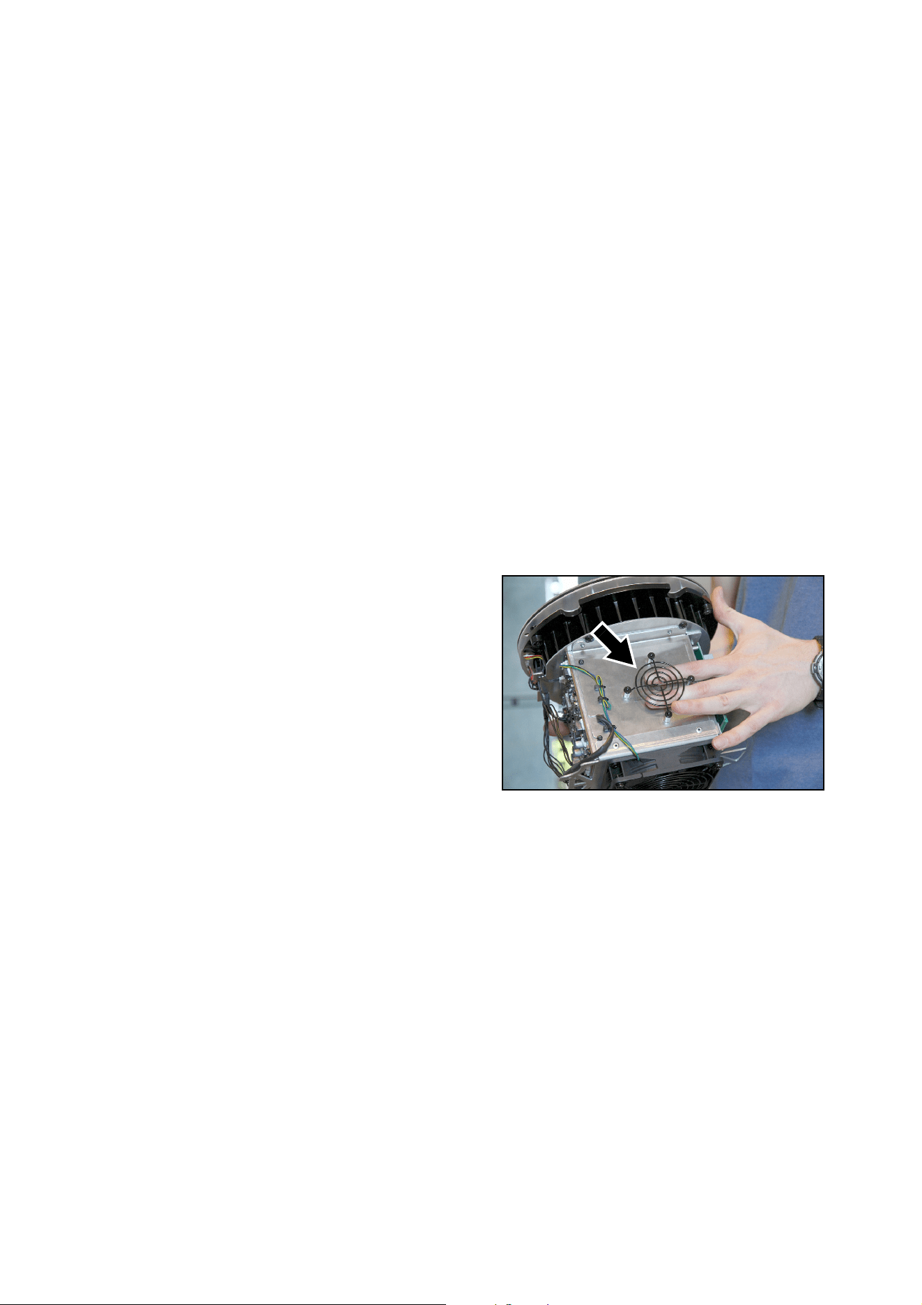
3. Lift the luminaire module out of the fixture
housing (a service tool is available from
Martin® that simplifies lifting the module
out of the housing – please contact
Martin® Service if you are interested).
See Figure 13. Remove a silica gel bag
from its wrap. Use a cable tie to fasten
the bag behind the frame (arrowed) on
the side of the module. Then lower the
module back into the housing.
4. Place the fixture next to the installation
sleeve and connect it as described in the
“AC power” and “DMX-RDM data”
chapters later in this manual.
5. Lower the fixture without the top glass
and top ring into the installation sleeve.
Figure 13: Frame for fastening silica gel bag
20 Inground 400 range user manual
6. See Figure 14. The holders for diffusers and DTFs (directional turning films) have an orientation mark:
• In fixtures with directional beam angles, this mark indicates the direction of the light output and must
point towards the surface to be illuminated.
• In fixtures with asymmetric beam angles, this mark indicates the axis of the narrow beam angle.
If necessary, rotate the holder with the diffuser or directional turning film to adjust the beam aiming.
7. Place the fixture next to the installation sleeve and connect it as described in the “AC power” and
“DMX-RDM data” chapters later in this manual.
8. Apply a small amount of grease or anti-seize compound to the threads of the three original mounting
bolts from the Inground 200.
9. Prepare the mounting clamps for the Inground 400 fixture as described shown in Figure 15:
Figure 14: Orientation mark in diffuser holder
Wide
angle
Narrow
angle
Direction of
light output
A
B
C
A
B
C
D
A
B
C
D
A
B
C
D
Pass each of the three
mounting bolts (A)
through one of the three
holes in the top ring (B)
and screw the bolt
through a clamp block
(C).
Screw a self-locking nut
(D) onto the end of each
bolt until the nut is flush
with the end of the bolt.
Do not screw the nut any
further up the bolt.
Unscrew each bolt (A)
back up through the
clamp block (C) until the
retaining nut (D) touches
the clamp block.
Figure 15: Preparing mounting clamps
Physical installation 21
10. Clamp the fixture into the installation sleeve as shown in Figure 16:
11. With directional and asymmetric beam angle fixtures, check that the orientation of the diffuser holder is
still correct (see Figure 14).
12. Use a torque driver to cross-tighten the clamp bolts to a torque of 6 Nm.
13. Apply a small amount of grease or anti-seize
compound to the original six M6 x 25 top ring screws
from the Inground 200 and use them to fasten the
original top glass and top ring onto the new Inground
400. See Figure 17. Use a torque driver and
cross-tighten the top rings screws gradually in at least
three stages until you reach a torque of 9 Nm.
A
B
E
C
D
B
E
Tighten the three clamp
bolts (A) to around 1 Nm.
Holding the fixture by the
inside rim of the housing,
begin lowering it into its
sleeve.
As you lower the fixture, ensure that the clamp blocks
(C) pass between the fins in the sleeve so that the
outer rim (B) sits on the fins (E). Then rotate the
fixture so that the clamp blocks locate under the fins.
Figure 16: Retrofit installation, fastening fixture into installation sleeve
$
'
(
)
%
&
Figure 17: Top ring screw tightening
sequence
22 Inground 400 range user manual
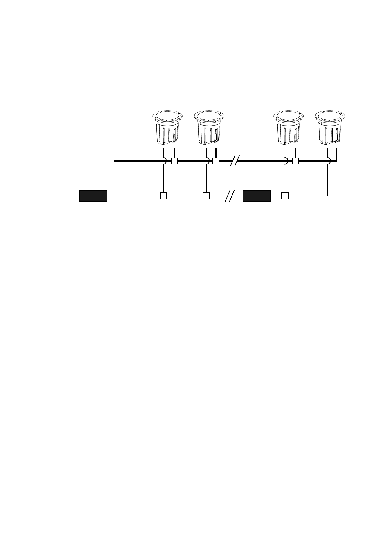
Power and data cable layout
Figure 18 gives a schematic diagram of the cable layout in an Inground 400 installation.
Note the following points:
• You must add an RDM-compatible optically-isolated amplifier-splitter to the data link each time you reach
32 fixtures or 500 m (1640 ft.). You must also use this type of amplifier-splitter if you need to split the data
link into two or more branches.
• Figure 18 shows one DMX universe only. If the fixtures on the data link occupy all of the 512 channels in
one DMX universe, create a new DMX universe just like the one shown in Figure 18. The new DMX
universe must have its own data link and its own DMX output from the controller.
Your Martin® supplier will be glad to help and advise on all aspects of system planning and cable layout.
DMX-RDM splitter
(required after 32
luminaires or 500 m)
Data
RDM-compatible
DMX controller
AC mains
power
Power
Figure 18: Schematic cable layout

AC power 23
AC power
Warning! Read “Safety Information” on page 3 before attempting to install a fixture. Lock out power
to the entire installation before working on cables and connections or removing any cover.
Warning! Electrical installation must be carried out by qualified professionals only.
Warning! For protection from dangerous electric shock, the fixture must be grounded (earthed). The
AC power distribution system must be fitted with current overload and ground-fault (earth-fault)
circuit breakers as well as a means to isolate fixtures from power and lock out power during service.
Important! Do not connect a fixture to an electrical dimmer system. Doing so can damage the
electronics.
See Figure 18 on page 22 for a schematic diagram of cable layout. If you require help in planning or
dimensioning the power distribution system, please contact your Martin® supplier for assistance.
If there is a break or cut at any point in a cable (for example at a connection point), and if this is exposed to
water, moisture can be drawn up the inside of the cable due to the vacuum effect of temperature fluctuations
during operation. Ensure that the fixture is protected from the entry of water via the power cable by using
IP67-rated junction boxes filled with two-component potting compound and by protecting connectors with
weatherproof housings.
The Inground 400 range is supplied in EU and US models. Both models accept AC power at 100 - 277 V
nominal, 50 or 60 Hz. Do not connect to power at any other voltage or frequency.
There is no power on/off switch. Power is applied to a fixture as soon as it is connected to power. Provide a
means to disconnect from power or shut down power to fixtures that is easily accessible and is located close
to the fixtures.
Connecting to power
The fixture is supplied with an integral power cable tail ready for connection to a single-phase 3-wire (live,
neutral, ground/earth) power distribution system at 100 - 277 V nominal, 50/60 Hz.
Warning! If you have any other type of distribution system than the one listed above, contact your
Martin® supplier for assistance.
When connecting the power cable to a power distribution circuit, use a terminal block with three screw
terminals rated 300 volts, 5 amps minimum, inside an IP67-rated junction box. Use cable glands for cable
entry. Twist the bare ends of the wires in the power cable before inserting in the terminals and make sure
that no copper strands protrude from the terminals. Fill the junction box with two-component potting
compound when you have made connections and before installing the junction box lid.
Making connections
To connect a fixture to a single-phase 3-wire (live, neutral, ground/earth) power system:
1. Lock out power to the installation.
2. Pass the power input and power output (throughput) cable and the fixture’s power cable tail through
cable glands into a new, unused IP67-rated junction box.

24 Inground 400 range user manual
3. Connect the wires in the cable tail to the power input and output cables following the color code for US
and EU models given in Table 1. Connect the conductors in the power cable to the distribution circuit as
follows:
- Connect the green wire (US models) or yellow/green wire (EU models) to ground (earth)
- Connect the white wire (US models) or blue wire (EU models) to neutral
- Connect the black wire (US models) or brown wire (EU models) to live.
4. Fill the junction box with two-component potting compound to seal it.
5. Check that all installation work is completed and carry out appropriate tests and safety checks before
applying AC mains power.
Power plug
For temporary use in a dry environment only, it is possible to install a plug (cord cap) that is suitable for your
AC power outlets on the end of the supplied power cable. If you do this, install a grounding-type (earthed)
plug with integral cable grip that is rated for the AC power voltage and 5 amps minimum, following the plug
manufacturer’s instructions. Table 1 on page 24 shows some possible pin identification schemes; if pins are
not clearly identified, or if you have any doubts about proper installation, consult a qualified electrician.
Wire color
(US models)
Wire color
(EU models) Conductor Symbol Screw (US)
black brown live L yellow or brass
white blue neutral N silver
green yellow/green ground (earth) or green
Table 1: Conductor identification

DMX-RDM data 25
DMX-RDM data
Fixtures must be connected via a data link for DMX and RDM communication.The following considerations
must be taken into account when planning the data link:
• RS-485 data cable designed for exterior use is required for outdoor installations. RS-485 cable has low
capacitance and a characteristic impedance of 85 to 150 Ohms. It is electrically shielded and has at least
1 twisted pair of conductors. The minimum recommended wire size is 0.25 mm
2
(24 AWG) for runs up to
300 meters (1000 ft.) and 0.32 mm
2
(22 AWG) for runs up 500 meters (1640 ft). You can use CAT 5
network cable designed for direct burial in outdoor installations, but we recommend that you run it inside
conduit.
• The maximum permitted control data cable length before a control signal amplifier is required is 500
meters (1640 ft.).
• Fixtures must be ‘daisy-chained’, i.e. the data cable must be connected in one single chain of fixtures. If
you want to split the chain into two or more branches, you must use an amplifier-splitter (see below).
• Each chain may connect a maximum of 32 fixtures.
• An optically isolated amplifier-splitter such as the Martin® DMX 5.3 Splitter (P/N 90758140) or the
RDM-compatible Martin® RDM 5.5 Splitter (P/N 90758150) must be used to:
- extend a link beyond 500 meters (1640 ft.)
- extend the link to include a further maximum 32 fixtures, or
- branch the link into further single chains, each containing 32 fixtures. The Martin® amplifier-splitters
mentioned above allow a link to be branched into four new chains.
• Each chain on the link must be terminated by installing a 120 ohm resistor (available from Martin,
P/N 04150308) across the data hot (+) and cold (-) conductors of the last fixture on the chain.
• Long parallel runs of AC power and control data cables may cause interference on the data link and must
be avoided. Even if not required by law, use separate conduits for power and data cables.
• One DMX universe has 512 DMX control channels available. If individual control of the fixtures in an
installation is required, each fixture must be given its own channels until the limit of 512 is reached. At this
point, a new DMX universe must be created before more fixtures can be added.
• The number of fixtures that can be individually controlled in one DMX universe depends on the number of
DMX channels they use. if an Inground 400 fixture is set to HSI mode, for example, that fixture will require
3 DMX channels (one channel for hue, one for saturation and one for intensity). The total number of
fixtures set to HSI mode that can be linked in one DMX universe will therefore be 512/3 = 170 (note that
an amplifier-splitter must be used each time the limit of 32 devices on one branch is reached).
Connecting the data link
Warning! Lock out power to the entire installation before working on cables and connections.
Warning! Make sure that data connections are totally protected from water, or moisture may be
drawn up the inside of the cable due to the vacuum effect from the heat generated during operation.
The fixture is supplied with a 1.8 meter (5.9 ft.) data cable tail for data connection. The cable contains both
input and output conductors that are identified as follows:
• 1 x shield = data input and output common
• 2 x white wires = data input and output hot (+)
• 1 x green wire = data input cold (-)
• 1 x brown wire = data output cold (-)
To connect a fixture to the data link:
1. Pass the data input and data output (throughput) cable and the fixture’s cable tail through cable glands
into a new, unused IP67-rated junction box.
2. Connect the wires in the cable tail to the data input and output cables following the above color code.
3. Fill the junction box with two-component potting compound to seal it.

26 Inground 400 range user manual
Installing data connectors
You will probably need to install input and output connectors on the data cable for connection to a
DXM/RDM control device or a splitter-amplifier, for example. When you install a connector:
• Respect the pinouts given below.
• Use a male connector to accept data input and a female connector to give data output.
• Do not connect the shield conductor to ground (earth) or allow it to come into contact with a connector
shell, as this may cause interference.
• If the connector is not installed in a dry location, protect it in a weatherproof housing if it is not totally
weatherproof.
XLR connection
XLR connectors are suitable if DMX cable is used for the data link. XLR pin numbers are normally marked
on connectors. Connectors must be wired using the standard XLR DMX pin-out:
• Pin 1: Cable shield
• Pin 2: DMX Data 1 - (cold)
• Pin 3: DMX Data 1 + (hot)
Pins 4 and 5 on 5-pin XLR connectors are not currently used but are available for additional connections in
line with the USITT DMX-512A standard. The required pinout is:
• Pin 4: DMX Data 2 - (cold)
• Pin 5: DMX Data 2 + (hot)
To avoid ground loop / earth loop problems, ensure that the DMX cable shield does not come into contact
with the shell or body of XLR connectors.
RJ-45 connection
RJ-45 connectors are suitable if CAT 5 cable is used for the data link. RJ-45 cable connector pins are
numbered from the left looking at the face of the connector with the locking clip on top (see Figure 19).
Connectors must be wired according to the 568-B system using the standard RJ-45 pin-out for DMX
applications:
• Pin 1 (White/orange): DMX data hot (+)
• Pin 2 (Orange): DMX data cold (-)
• Pins 7 (White/brown) and 8 (Brown): Common
Pins 3 and 6 are available for Data 2 connections in DMX 512-A or
similar systems. They must be wired as follows:
• Pin 3 (White/green): Available for Data 2 hot (+)
• Pin 6 (Green): Available for Data 2 cold (-)
Pins 4 and 5 are not used in currently available lighting control
systems but can be wired as follows:
• Pin 4 (Blue)
• Pin 5 (White/blue)
Pin 1 Pin 8
Figure 19: RJ-45 cable
connector pins

Fixture setup 27
Fixture setup
RDM (Remote Data Management) is required to set up fixtures in the Inground 400 range.
We recommend the use of Martin® M-PC to configure fixtures. M-PC is an RDM-compatible DMX controller
application that runs on a Windows PC. See the Martin® M-PC user documentation for details of how to use
RDM to set up fixtures.
DMX addresses
If individual control of fixtures is required, each fixture must be set up to receive instructions from the DMX
controller on a group of DMX channels that are not used by any other device in its DMX universe. The DMX
address, also known as the control address or start channel, is the first of these channels. Each fixture uses
this channel and the channels immediately above it to receive instructions.
Fixtures use 2, 3 or 4 DMX channels, depending on model and DMX color control mode. For example, if a
fixture’s DMX address is set to 1 and the fixture is in RGB DMX mode, it will use channels 1 - 3. Channel 4
will be available as the DMX address for the next fixture.
If two or more identical fixtures are set up with the same DMX address and in the same DMX mode, they will
receive the same instructions and behave identically. Setting up identical fixtures with the same address is a
good tool for troubleshooting unexpected behavior and an easy way to achieve synchronized action.
Setting DMX addresses via RDM involves running a scan to identify the fixtures that are present on the data
link and then allocating addresses either automatically or manually.
DMX control modes
The DMX Mode setting available via RDM allows you to set fixtures to various control modes.
Bear in mind that changing the DMX mode may affect the number of DMX channels the fixture uses.
The following DMX control modes are available:
Inground 400, Inground 410
• RAW (Individual control of red, green, blue and white LED groups - uncalibrated)
• RGB (red, green, blue - calibrated, all LEDs including white can be activated to optimize color and
intensity)
• HSI (hue, saturation, intensity - calibrated)
• HSIC (hue, saturation, intensity, color temperature - calibrated)
• ICMY (intensity, cyan, magenta, yellow - calibrated)
Inground 420
• RAW (Individual control of warm white and cold white LED groups - uncalibrated)
• CT (intensity, color temperature - calibrated)

28 Inground 400 range user manual
Operation
Inground 400 range fixtures can be operated using a DMX controller or programmed to run a standalone
light show without DMX control.
Heat management
Ambient temperature
Fixtures can be operated at ambient temperatures from -30° C (-22° F) to 45° C (113° F).
At temperatures below 0° C (32° F), you can dim LEDs to zero if light output is not required but you should
leave power constantly applied. The standby power will provide a a low level of heat to help protect circuits
and components from the effects of low temperature.
Temperature-regulated light output
Fixtures in the Inground 400 range regulate their internal temperature by gradually reducing light output as
they approach maximum operating temperature. This feature gives the highest possible light output level at
any given ambient temperature while keeping the product within thermal limits and thus ensuring optimum
product lifetime. In fact, LEDs create far less heat than other light sources and the Inground 400 range is
designed to ensure effective heat dissipation as well as maximum light output.
In a typical operation situation in temperate latitudes, i.e. 20° C (68° F) ambient temperature and sleeve
mounted in moist soil, the fixture will operate at around 90% of full output when it has reached steady state.
You can expect light intensity to be higher than normal when the fixture is first powered on, especially if the
fixture is operated in cold conditions. There will then usually be a reduction in light intensity, typically after 2
- 4 hours. The size of the reduction from cold start to steady state intensity will vary. In cold conditions and if
colored light output is used rather than white output, the reduction can be zero or close to zero. In this case
output intensity will be higher than the product is specified to. In high ambient temperatures and if full
intensity white light is used, the reduction from cold start intensity level to the product’s specified steady
state level will be significant: LED power can be reduced by up to approximately 50% in extreme conditions.
But even in this situation, the fixture will not reduce light output to below its specified steady state level if it is
correctly installed and the front glass is kept clean.
DMX control
In DMX-controlled operation, the options available at the DMX controller depend on which DMX mode the
fixture is set to (see “DMX control modes” on page 27).
“DMX protocols” on page 31 gives full details of the control options in the Inground 400 range.
Setup via RDM
The Inground 400 range is compatible with RDM (Remote Device Management). Using an RDM-compliant
DMX controller, you can communicate with all the fixtures on a data link without needing to connect to each
fixture individually. RDM lets you set the DMX addresses of all the fixtures on the link, carry out fixture
configuration and retrieve fixture data including details of any error that has been logged.
To use RDM:
1. Obtain an RDM-compatible controller such as the Martin® M-PC application running on a Windows PC.
2. Use a USB cable to connect the PC to a USB/DMX interface box such as the Martin® M-DMX.
3. Connect the interface box to the data link.
4. Power the fixture on and carry out an RDM discovery / scan in M-PC or your RDM-compatible controller.
5. You can then configure or retrieve data from the fixtures on the data link.

Service and maintenance 29
Service and maintenance
Warning! The light source contained in the fixture is not user-replaceable. If replacement is necessary, it must
be carried out by Martin® or an authorized Martin® service agent.
Important! Please consult your Martin® supplier if a fixture requires any service other than cleaning or a
firmware update.
Fixtures require cleaning to maintain reliable operation and protect the investment it represents.
Excessive dirt buildup on or around the top glass degrades performance, causes overheating and
will damage the fixture. Damage caused by inadequate cleaning is not covered by the product
warranty.
It is Martin® policy to use the best quality materials available to ensure optimum performance and the
longest possible component lifetimes. However, optical components in all lighting fixtures are subject to
wear and tear over the life of the fixture, resulting in gradual changes in color rendition, for example. The
extent of wear and tear depends heavily on operating conditions, maintenance and environment, so it is
impossible to specify precise lifetimes for optical components. However, you will eventually need to have
LEDs replaced if their characteristics are affected by wear and tear after an extended period of use and if
you require fixtures to perform within very precise optical and color parameters.
Opening the fixture
Fixtures in the Inground 400 range are supplied as sealed units. If service access inside the fixture is
required, please consult your Martin® supplier.
Opening and closing fixtures requires care in order to avoid humidity inside the fixture that can cause
condensation on the top glass. For example, you will need to order silica gel bags from Martin®. You must
remove a bag from its sealed foil wrap and replace the bag inside the fixture (see Figure 13 on page 19),
then close the fixture as soon as possible.
Cleaning
Regular cleaning is essential for fixture life and performance. Buildup of dust and dirt degrades the fixture’s
light output and cooling ability.
Cleaning schedules will vary greatly depending on the operating environment. It is therefore impossible to
specify precise cleaning intervals. If in doubt, consult your Martin® dealer about a suitable maintenance
schedule.
Do not use products that contain solvents, abrasives or caustic agents for cleaning, as they can cause
surface damage to the fixture.
Warning! Do not use a high-pressure water jet for cleaning.
The top glass can be cleaned with mild detergents such as those for washing cars. To clean the glass:
1. Shut down AC power and allow the fixture to cool for 20 minutes.
2. Rinse off loose dirt with a hosepipe or low-pressure water spray. Check that the installation sleeve does
not fill with water.
3. Wash the glass using warm water with a little mild detergent and a soft brush or sponge. Do not use
abrasive cleaners.
4. Rinse with clean water and wipe dry.
30 Inground 400 range user manual
Optical configurations
Various beam angle and beamshaper options are available for the Inground 400 range. Fixtures are ordered
preconfigured with the required option. If you wish to change the configuration of a fixture, please contact
your Martin® supplier.
The powerful LEDs in the Inground 400 range can present a risk of eye injury if they are not covered by a
diffuser. Do not operate a fixture without a diffuser lens installed.
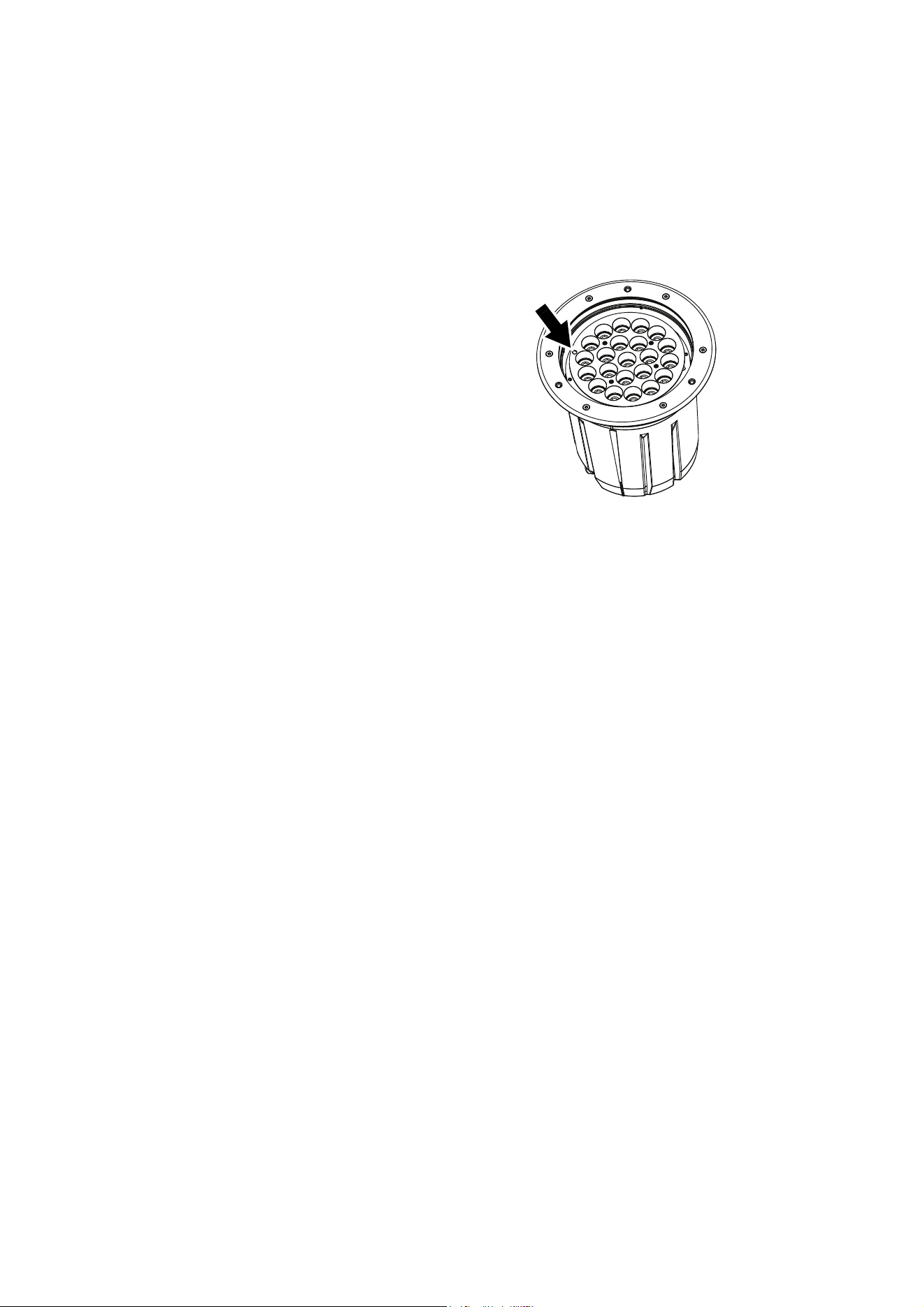
Status indicator
See Figure 20. A status LED is situated close
to the edge of the main LED array under the
top glass. To see the status LED, reduce light
output to zero, then look directly down through
the top glass from close to the fixture.
The LED gives the following information:
Fixture operating status
• LED green = normal status
• LED red = fixture reports error, please check
fixture status via RDM
• LED yellow = fixture in boot mode for
firmware update (Martin® Service use only).
As well as the above, the LED also shows DMX
status by flashing or lighting constantly:
DMX signal status
• LED flashes = no valid DMX signal present
• LED lights constantly = fixture receiving valid DMX signal
Updating fixture software
It may be necessary to upload new fixture software (firmware) to an Inground 400 range fixture if you believe
that the product has a software-related fault or if you want to update to a newer version. Software updates
are available from the Martin® website (http://www.martin.com) and can be installed via the DMX data link
with the following items:
• The Martin® DMX Tools suite of Windows-based utilities. You can download Martin® DMX Tools free of
charge from the Martin® website at www.martin.com.
• The fixture’s main CPU software update file, downloadable free of charge from the Inground 400 range
Tech Docs / Support area on the Martin® website (this file can be downloaded automatically from within
the Martin® Uploader application)
• A Martin® M-DMX Interface or similar PC/fixture hardware interface and a Windows PC.
Installing software
1. Connect a Martin® M-DMX or similar USB/DMX interface device to the DMX data link that the fixtures
are connected to. The fixture software will be uploaded to all the fixtures of the same type that are
powered on and connected on the DMX link.
2. Using a USB cable, connect a Windows PC running Martin® DMX Tools to the USB/DMX interface
device.
3. Open Fixture Uploader, one of the applications included in Martin® DMX Tools. Upload the fixture
software as described in the Fixture Uploader application or user documentation.
4. Shut down Martin® DMX Tools.
5. Cycle power off and on. Check that the fixture resets and operates correctly.
Figure 20: Status indicator LED

DMX protocols 31
DMX protocols
Inground 400, Inground 410
RAW mode, uncalibrated
RGB mode, calibrated
All LEDs – including white – can be activated to obtain the calibrated target color at maximum intensity.
HSI mode, calibrated
Start code = 0
Channel Value Percent Function
1
0 - 255 0 - 100
Red
Intensity 0 →100%
2
0 - 255 0 - 100
Green
Intensity 0
→100%
3
0 - 255 0 - 100
Blue
Intensity 0 →100%
4
0 - 255 0 - 100
White
Intensity 0 →100%
Start code = 0
Channel Value Percent Function
1
0 - 255 0 - 100
Red
Intensity 0 →100%
2
0 - 255 0 - 100
Green
Intensity 0 →100%
3
0 - 255 0 - 100
Blue
Intensity 0
→100%
Start code = 0
Channel Value Percent Function
1
0 - 255 0 - 100
Hue
Red → Orange → Ye l l o w → Green →
Cyan → Blue → Indigo → Violet →
Magenta
→ Red
2
0 - 255 0 - 100
Saturation
Zero (white) → Full
3
0 - 255 0 - 100
Intensity
Intensity 0 →100%

32 Inground 400 range user manual
HSIC mode, calibrated
ICMY mode, calibrated
Inground 420
RAW mode, uncalibrated
CT mode, calibrated
Start code = 0
Channel Value Percent Function
1
0 - 255 0 - 100
Hue
Red
→ Orange → Ye l l o w → Green →
Cyan → Blue → Indigo → Violet →
Magenta → Red
2
0 - 255 0 - 100
Saturation
Zero (white)
→ Full saturation
3
0 - 255 0 - 100
Intensity
Intensity 0 →100%
4
0 - 255 0 - 100
Color Temperature Control
Warm → cold
Start code = 0
Channel Value Percent Function
1
0 - 255 0 - 100
Intensity
Intensity 0
→100%
2
0 - 255 0 - 100
Cyan
Zero (white) → Full saturation
3
0 - 255 0 - 100
Magenta
Zero (white) → Full saturation
4
0 - 255 0 - 100
Yellow
Zero (white)
→ Full saturation
Start code = 0
Channel Value Percent Function
1
0 - 255 0 - 100
Warm white
2700 K Intensity 0
→100%
2
0 - 255 0 - 100
Cool white
6500 K Intensity 0 →100%
Start code = 0
Channel Value Percent Function
1
0 - 255 0 - 100
Intensity
Intensity 0 →100%
2
0 - 255 0 - 100
Color temperature control
3000 K
→ 6500 K

Troubleshooting 33
Troubleshooting
If the fixture fails to reset or operate correctly, cycle power off and on again and try again. If the fixture still
does not reset or operate correctly, repeat the software upload. You can also check to see whether it is
sending an error message via RDM that may identify the cause of
Problem Probable cause(s) Remedy
Fixture is completely dead.
No power to fixture. Check power and connections.
Primary fuse blown. Isolate fixture from power. Check fuse and replace.
One or more fixtures responds
incorrectly to control or does not
respond at all.
Fault on DMX link.
Inspect connections and cables. Correct poor
connections. Repair or replace damaged cables.
Incorrect fixture addressing.
Check fixture is set to correct DMX mode.
Check number of channels required by fixture’s
DMX mode and check fixture addresses.
Fixture defective.
Have faulty fixture serviced by Martin® service
technician.
Other device on DMX link defective.
Bypass devices on DMX link until the faulty device
has been identified.
Have faulty device tested and serviced by Martin®
service technician or device supplier.
Light output intensity falls
excessively.
Fixture is hot. Output intensity is
temperature-regulated and has been reduced
to keep fixture within optimum temperature
range.
Check that ambient temperature does not exceed
maximum permitted level.
Check fixture temperature via RDM.
Clean top glass.
Contact Martin® for service.
One or more fixtures fails to
restart or operate correctly after
updating fixture software.
Fixture software not fully installed. Cycle power off and on again.
Data corrupted during upload. Repeat fixture software upload procedure.
Table 2: Troubleshooting

34 Inground 400 range user manual
Specifications
Physical
Fixture
Height without top ring . . . . . . . . . . . . . . . . . . . . . . . . . . . . . . . . . . . . . . . . . . . . . . . . . . . .313 mm (12.4 in.)
Height with top ring installed . . . . . . . . . . . . . . . . . . . . . . . . . . . . . . . . . . . . . . . . . . . . . . .321 mm (12.7 in.)
Outer diameter at top of fixture . . . . . . . . . . . . . . . . . . . . . . . . . . . . . . . . . . . . . . . . . . . . .310 mm (12.2 in.)
Weight . . . . . . . . . . . . . . . . . . . . . . . . . . . . . . . . . . . . . . . . . . . . . . . . . . . . . . . . . . . . . . . 14.7 kg (32.5 lbs.)
Top ring (trim ring)
Flush-mount top ring outer diameter . . . . . . . . . . . . . . . . . . . . . . . . . . . . . . . . . . . . . . . . :329 mm (13.0 in.)
Flush-mount top ring thickness . . . . . . . . . . . . . . . . . . . . . . . . . . . . . . . . . . . . . . . . . . . . . . . .7 mm (0.3 in.)
Beveled top ring outer diameter. . . . . . . . . . . . . . . . . . . . . . . . . . . . . . . . . . . . . . . . . . . . .340 mm (13.4 in.)
Beveled top ring thickness . . . . . . . . . . . . . . . . . . . . . . . . . . . . . . . . . . . . . . . . . . . . . . . . . . . .5 mm (0.2 in.)
Installation sleeve
Installation sleeve height . . . . . . . . . . . . . . . . . . . . . . . . . . . . . . . . . . . . . . . . . . . . . . . . . .400 mm (15.8 in.)
Installation sleeve internal diameter. . . . . . . . . . . . . . . . . . . . . . . . . . . . . . . . . . . . . . . . . .334 mm (13.2 in.)
Installation sleeve base flange external diameter . . . . . . . . . . . . . . . . . . . . . . . . . . . . . . .416 mm (16.4 in.)
Total height, installation sleeve with fixture and flush top ring . . . . . . . . . . . . . . . . . . . . . .402 mm (15.9 in.)
Total height, installation sleeve with fixture and beveled top ring. . . . . . . . . . . . . . . . . . . .408 mm (16.1 in.)
Dynamic Effects
Inground 400, Inground 410
Color mixing. . . . . . . . . . . . . . . . . . . . . . . . . . . . . . . . . . . . . . . . . . . . . . . . . . . . . . . . . . . . . . . . . . . . RGBW
Red . . . . . . . . . . . . . . . . . . . . . . . . . . . . . . . . . . . . . . . . . . . . . . . . . . . . . . . . . . . . . . . . . . . . . . . . .0 - 100%
Green. . . . . . . . . . . . . . . . . . . . . . . . . . . . . . . . . . . . . . . . . . . . . . . . . . . . . . . . . . . . . . . . . . . . . . . .0 - 100%
Blue . . . . . . . . . . . . . . . . . . . . . . . . . . . . . . . . . . . . . . . . . . . . . . . . . . . . . . . . . . . . . . . . . . . . . . . . .0 - 100%
White . . . . . . . . . . . . . . . . . . . . . . . . . . . . . . . . . . . . . . . . . . . . . . . . . . . . . . . . . . . . . . . . . . . . . . . .0 - 100%
Inground 420
Color temperature control . . . . . . . . . . . . . . . . . . . . . . . . . . . . . . . . . . . . . . . . . . . . . . . . . . . 2700 - 6500 K
Warm white (3000 K in Calibrated mode) . . . . . . . . . . . . . . . . . . . . . . . . . . . . . . . . . . . . . . . . . . . .0 - 100%
Cool white (6500 K in Calibrated mode) . . . . . . . . . . . . . . . . . . . . . . . . . . . . . . . . . . . . . . . . . . . . .0 - 100%
Control and Programming
All models
Control options. . . . . . . . . . . . . . . . . . . . . . . . . . . . . . . . . . . . . . . . . . . . . . . . . . . . . . . . . . . . . . .DMX, RDM
DMX address setting and fixture setup . . . . . . . . . . . . . . . . . . . . . . . . . . . . . . . . . . . . . . . . . . . . . . . . .RDM
Fixture status monitoring . . . . . . . . . . . . . . . . . . . . . . . . . . Multi-color status LED visible through top glass
Firmware update . . . . . . . . . . . . . . . . . . . . . . . . . . . . . . . . . . . . . . . . . . . . . . . . .Serial upload via DMX link
DMX compliance . . . . . . . . . . . . . . . . . . . . . . . . . . . . . . . . . . . . . . . . . . . . . . . . . . . . . . . USITT DMX512-A
RDM compliance . . . . . . . . . . . . . . . . . . . . . . . . . . . . . . . . . . . . . . . . . . . . . . . . . . . . . . . . . . . . ANSI E1.20
Receiver. . . . . . . . . . . . . . . . . . . . . . . . . . . . . . . . . . . . . . . . . . . . . . . . . . . . . . . . . . . . . . . . . . . . . . .RS-485
Inground 400, Inground 410
Color control modes. . . . . . . . . . . . . . . . . . . . . . . . . . . . . . . . . . . . . . . . . . . . RAW, RGB, HSI, HSIC, ICMY
DMX channels . . . . . . . . . . . . . . . . . . . . . . . . . . . . . . . . . . . . . . . . . . . . . . . . . . . . . . . . . . . . . . . . . . . 3 or 4
Inground 420
Color temperature control modes . . . . . . . . . . . . . . . . . . . . . . . . . . . . . . . . . . . . . . . . . . . . . . . . RAW, CTC
DMX channels . . . . . . . . . . . . . . . . . . . . . . . . . . . . . . . . . . . . . . . . . . . . . . . . . . . . . . . . . . . . . . . . . . . . . . .2
Optics
All models
Minimum LED lifetime . . . . . . . . . . . . . . . . . . . . . . . . . . . . . . . . . 50 000 hours (to >70% luminous output)*
*Figure obtained under manufacturer's test conditions
Exterior Inground 400
Light source . . . . . . . . . . . . . . . . . . . . . . . . . . . . . . . . . . . . . . . . . . . .56 x R, G, B and W single-color LEDs
Beam angle options . . . . . . . . . . . . . . . . . . . . . . . . . . . . . . . . . . . . . . . . . . . . . . .7°, 14°, 31°, 57°, 10° x 60°

Specifications 35
Exterior Inground 410
Light source . . . . . . . . . . . . . . . . . . . . . . . . . . . . . . . . . . . . . . . . . . . . . . . . . . 22 x RGBW quad-color LEDs
Beam angle options . . . . . . . . . . . . . . . . . . . . . . . . . . . . . . . . . . . . . . . . . . . . . .19°, 22°, 29°, 50°, 20° x 61°
Exterior Inground 420
Light source . . . . . . . . . . . . . . . . . . . . . . . . . . . . . . . . . . . . . . . . . . . . . . . . . .56 x 2700 K and 6500 K LEDs
Beam angle options . . . . . . . . . . . . . . . . . . . . . . . . . . . . . . . . . . . . . . . . . . . . . . .7°, 14°, 31°, 57°, 10° x 60°
Construction
Housing . . . . . . . . . . . . . . . . . . . . . . . . . . . . . . . . . . . . . . . . . . . . . . . . . . . . . . . . . . . . . . . . . . . . .Aluminum
Finish . . . . . . . . . . . . . . . . . . . . . . . . . . . . . . . . . . . . . . . . . . . . . . . . . . Anodized, then black powder coated
Top ring . . . . . . . . . . . . . . . . . . . . . . . . . . . . . . . . . . . . . . . . . . . . . . . . . . . . . . . . . . . . . . . . . Stainless steel
Top glass . . . . . . . . . . . . . . . . . . . . . . . . . . . . . . . . . . . . . . . . . . . . . . . . . . . . . . 19 mm (0.75 in.), tempered
Ingress protection rating . . . . . . . . . . . . . . . . . . . . . . . . . . . . . . . . . . . . . . . . . . . . . . . . . . . . . . . . . . . . IP67
Impact resistance. . . . . . . . . . . . . . . . . . . . . . . . . . . . . . . . . . . . . . . . . . . . . . . . . . . . . . . . . . . . . . . . . . IK10
Corrosion resistance . . . . . . . . . . . . . . . . . . . . . . . . . . . . C5-M (very high corrosivity / marine, ISO 12944)
Drive-over load resistance (in Martin® installation sleeve with stable groundwork) . . 40 000 N (8800 lbs.)
Installation sleeve . . . . . . . . . . . . . . . . . . . . . . . . . . . . . . . . . . . . . . . . . . . . . . . . . .Hot-dip galvanized steel
RoHS compliant
Installation
Installation method. . . . . . . . . . . . . . . . . . . . . . . . . . . . . . . . . . . . In installation sleeve (ordered separately)
Connections
Power cable entry . . . . . . . . . . . . . . . . . . . . . . . . . . . . . . . . . . . . . . . . . . . . . . . . . . . . . IP68/69 cable gland
Power connection. . . . . . . . . . . . . . . . . . . . . . . . . . . . . . . . . . . . . . . . . . 1.8 m (5.9 ft.) cable tail, bare ends
Data cable entry. . . . . . . . . . . . . . . . . . . . . . . . . . . . . . . . . . . . . . . . . . . . . . . . . . . . . . . IP68/69 cable gland
Data connection. . . . . . . . . . . . . . . . . . . . . . 1.8 m (5.9 ft.) combined input and output cable tail, bare ends
Electrical
AC power . . . . . . . . . . . . . . . . . . . . . . . . . . . . . . . . . . . . . . . . . . . . . . . . . . . 100 - 277 V nominal, 50/60 Hz
Power supply unit. . . . . . . . . . . . . . . . . . . . . . . . . . . . . . . . . . . . . . . . Integrated, auto-sensing multi-voltage
Power consumption, steady state, all LEDs at zero intensity. . . . . . . . . . . . . . . . . . . . . . . . . . . . . . . . .11 W
Typical Power and Current
100 V, 60 Hz. . . . . . . . . . . . . . . . . . . . . . . . . . . . . . . . . . . . . . . . . . . . . . . . . . . . . . . . 1.5 A, 149 W, PF 0.99
120 V, 60 Hz. . . . . . . . . . . . . . . . . . . . . . . . . . . . . . . . . . . . . . . . . . . . . . . . . . . . . . . . 1.3 A, 147 W, PF 0.99
208 V, 60 Hz. . . . . . . . . . . . . . . . . . . . . . . . . . . . . . . . . . . . . . . . . . . . . . . . . . . . . . . . 0.8 A, 145 W, PF 0.99
230 V, 50 Hz. . . . . . . . . . . . . . . . . . . . . . . . . . . . . . . . . . . . . . . . . . . . . . . . . . . . . . . . 0.7 A, 145 W, PF 0.98
277 V, 50 Hz. . . . . . . . . . . . . . . . . . . . . . . . . . . . . . . . . . . . . . . . . . . . . . . . . . . . . . . . 0.7 A, 145 W, PF 0.98
Measurements made at nominal voltage with all LEDs at full intensity. Allow for a deviation of +/- 10%.
Thermal
Cooling. . . . . . . . . . . . . . . . . . . . . . . . . . . . . . . . . . . . . . . . . . . . . . . . . . . . . . . . . . . Convection, internal fan
Maximum ambient temperature (Ta max.) . . . . . . . . . . . . . . . . . . . . . . . . . . . . . . . . . . . . . . . 45° C (113° F)
Minimum ambient temperature (Ta min.) . . . . . . . . . . . . . . . . . . . . . . . . . . . . . . . . . . . . . . . . -30° C (-22° F)
Maximum surface temperature, steady state, Ta=40° C . . . . . . . . . . . . . . . . . . . . . . . . . . . . 90° C (194° F)
Total heat dissipation (calculated, +/- 10%) . . . . . . . . . . . . . . . . . . . . . . . . . . . . . . . . . . . . . . . . 510 BTU/hr.
Approvals
EU safety . . . . . . . . . . . . . . . . . . . . . . . EN60958-2-13 (EN60598-1), EN62471, EN62493
EU EMC. . . . . . . . . . . . . . . . . . . . . . . . EN55015, EN61547, EN61000-3-2, EN6100-3-3,
US safety (pending) . . . . . . . . . . . . . . . . . . . . . . . . . . . . . . . . . . . . . . . . . . . ANSI/UL 1598
US EMC. . . . . . . . . . . . . . . . . . . . . . . . . . . . . . . . . . . . . . . . . . . . .47 CFR Part 15 Class A
Canadian safety (pending). . . . . . . . . . . . . . . . . . . . . . . . . . . . . . . . . .CSA C.22.2 No. 250
Australia/NZ (pending). . . . . . . . . . . . . . . . . . . . . . . . . . . . . . . . . . . . . . . . . . . . . . . . .RCM
Related Items
Martin® M-PC 2U including Martin® M-DMX Hardware Interface. . . . . . . . . . . . . . . . . . . . . P/N 90737070
Martin® M-PC Pro-64 / LJ-4 Controller Kit incl. Martin® M-DMX Hardware Interface . . . . . P/N 90737060
Martin® USB Tools package including Software Uploader . . . . . . . . Free download from www.martin.com
Please see www.martin.com for latest DMX/RDM controller and control interface product offers

36 Inground 400 range user manual
Ordering Information
Fixtures in the Inground 400 range can be ordered online at www.martin.com or by contacting your Martin®
supplier, selecting from the following configurations:
Series
• Inground 400 – 56 x R, G, B and W LEDs
• Inground 410 – 22 x quadcolor LEDs
• Inground 420 – 56 x cool white and warm white LEDs
Power
• EU – 220-240 VAC, 50 Hz
• US – 100-130 VAC, 60 Hz
Glare shield
• No glare shield
• Glare shield, 22 LEDs – for Inground 410
• Glare shield, 56 LEDs – standard (and required) for Inground 400 and 420
Beam shaper
• No diffuser
• Narrow diffuser
• Medium diffuser
• Wide diffuser
• 8° Directional and asymmetric
• 20° Directional
• Asymmetric
Top glass
• Standard
• Anti-skid
• No top glass
Top ring
A) New install:
•Beveled
•Flush
B) Retrofit, includes new top ring and glass, P/N 90507150HU, for existing Martin® Inground 200
installations:
• Old beveled (to match beveled top rings on existing Inground 200 fixtures)
• Old flush (to match flush mounting top rings on existing Martin® Inground 200 fixtures)
C) Retrofit, without top ring/glass, P/N 90507110HU, for existing Martin® Inground 200 installations:
• No top ring or front glass (re-use top rings and top glasses from existing Inground 200 fixtures)
Fixtures
The configuration options listed above are included under these part numbers:
Inground 4XX New Install . . . . . . . . . . . . . . . . . . . . . . . . . . . . . . . . . . . . . . . . . . . . . . . . .P/N 90507100HU
Inground 4XX Retrofit . . . . . . . . . . . . . . . . . . . . . . . . . . . . . . . . . . . . . . . . . . . . . . . . . . . .P/N 90507150HU
Inground 4XX Retrofit, without Top Ring/Glass . . . . . . . . . . . . . . . . . . . . . . . . . . . . . . . . .P/N 90507110HU
Installation Sleeve
Installation Sleeve for Inground 400. . . . . . . . . . . . . . . . . . . . . . . . . . . . . . . . . . . . . . . . . . . . P/N 91611841
Installation Lid for flush mount top ring installations . . . . . . . . . . . . . . . . . . . . . . . . . . . . . . . P/N 91616086
Installation Lid for beveled top ring installations. . . . . . . . . . . . . . . . . . . . . . . . . . . . . . . . . . . P/N 91616087
Installation sleeves are ordered separately from fixtures.
Specifications are subject to change without notice.
Data is valid for all models in range except where indicated.
See www.martin.com for latest specifications including full photometric data, etc.

Disposing of this product
Martin® products are supplied in compliance with Directive 2012/19/EC of the European
Parliament and of the Council of the European Union on WEEE (Waste Electrical and Electronic
Equipment), where applicable.
Help preserve the environment! Ensure that this product is recycled at the end of its life. Your
supplier can give details of local arrangements for the disposal of Martin® products.


www.martin.com • Olof Palmes Allé 18 • 8200 Aarhus N • Denmark
Tel: +45 8740 0000 • Fax +45 8740 0010