
Read this operation manual before using the product.
ENG
OPERATION MANUAL "LENS"
Zoom Lens
CN5x11
CN7x17

2
— FOREWORD —
Thank you for purchasing the Canon zoom lens.
This product comes with the following documents for the models mentioned below:
• Operation Manual "Before Using The Product" (Included with the product)
• Operation Manual "Regulations" (Included with the product)
• Operation Manual "Lens" (Web)
• Operation Manual "Information display" (Web)
• Depth-of-eld (Web)
Model Mount
CN5x11 IAS T/R1
RF
CN5x11 IAS T/P1
PL
CN7x17 KAS T/R1
RF
CN7x17 KAS T/P1
PL
NOTE
This lens is a zoom lens for shooting movies.
Depending on the camera attached or the function used, the lens may not operate properly or the indications may
not be correct.
In addition, do not operate the lens during initialization of the camera settings.
For other latest product information, please check our website.
Always use the latest version of the rmware for this lens and the camera.
When rmware updates are available, you can download the latest version of the rmware from the support
page.
RF-mount model: To update the rmware, insert an SD card containing the update le in the camera and ex-
ecute updating from the camera menu.
PL-mount model:To update the rmware, connect a USB device (USB ash drive) containing the update le
in the drive unit USB port and execute updating from the drive unit display.
For the availability of the latest version of the rmware and how to update it, refer to Canon's website.
https://cam.start.canon/
3
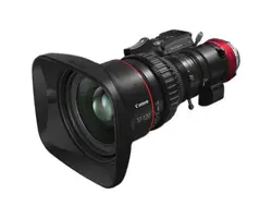
Make sure all of the following items are included in the packing box. If you nd any item missing, please contact your
Canon sales representative or dealer.
Accessories other than those mentioned above may be required depending on the specications of your unit.
For details, contact your Canon sales representative or dealer.
The illustrations in this manual are used as examples.
Actual forms may vary depending on models and specications.
PRODUCT LIST
Lens cap
Dust cap
Hood
Lens body
Drive unit xing
screws(×3)
Drive unit
storage bag
Attachment holder
Operation Manual
"Regulations"
Operation manual
"Before Using The Product"
Hood cap
4
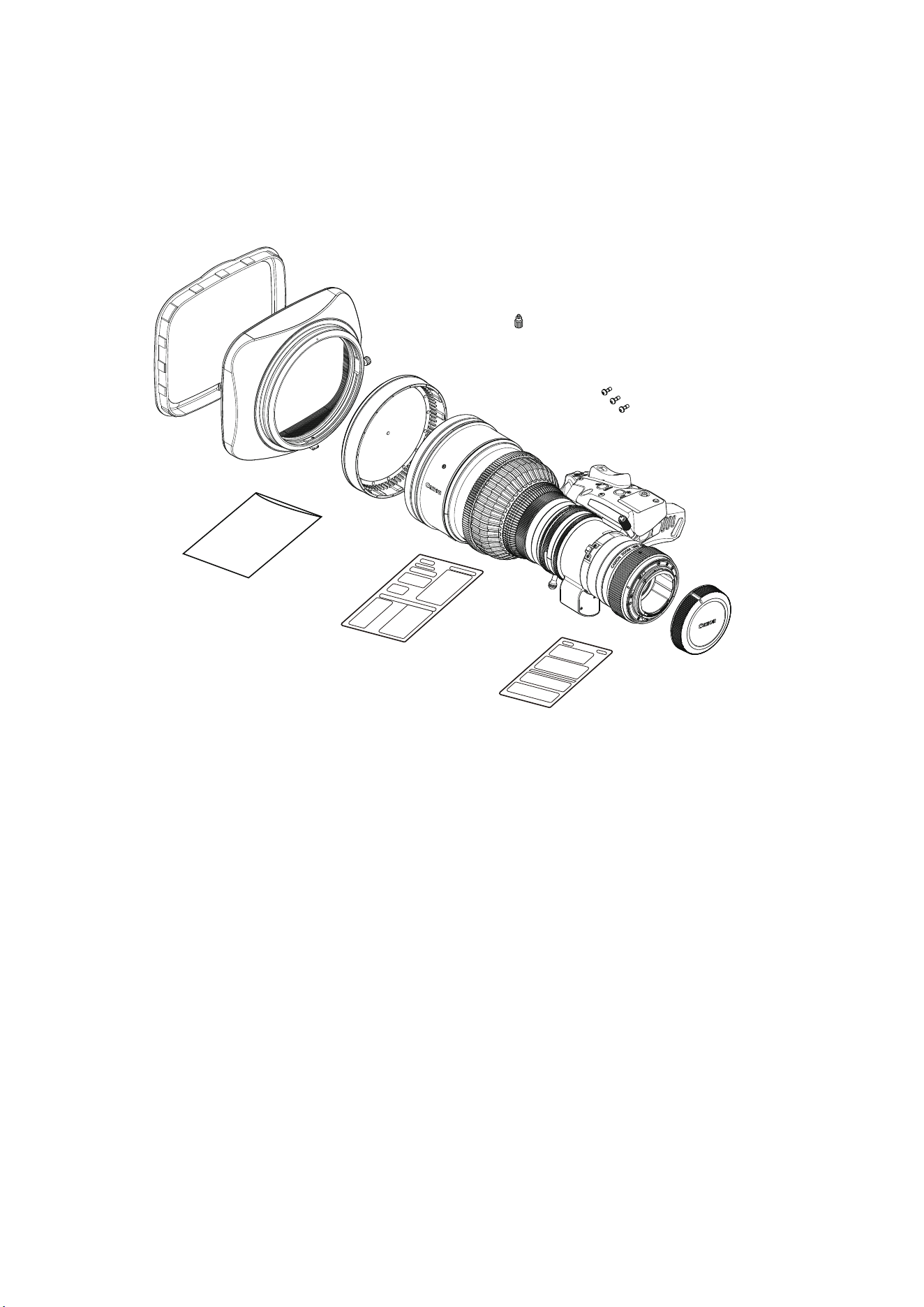
GENERAL SAFETY INFORMATION
The safety warnings and cautions provided on the product or in this operation manual must be observed.
Failure to observe these warnings and cautions provided to guard against hazards may result in injury or accident.
Read this operation manual carefully to familiarize yourself with its contents and ensure that you can operate the
product properly.
This manual uses the following symbols and terms in the warning and caution notices for preventing accidents and
protecting the safety of the customer and others.
WARNING
This indicates a potentially hazardous situation which, if not heeded, may result in
death or serious injury to you or others. Be sure to heed all warning notices to
ensure safe operation at all times.
CAUTION
This indicates a potentially hazardous situation which, if not heeded, may result in
a minor injury to you or others, or damage to property. Be sure to heed all caution
notices to ensure safe operation at all times.
NOTE
This indicates cautions and recommendations for operation. It contains information
which, if not heeded, may result in this product failing to function properly.
These notices also contain useful information for operation.
HANDLING THE PRODUCT
WARNING
1. Do not get this product wet or allow liquid inside. If water gets inside, stop using the product immediately. Continuing
to use the product under this condition may cause a re or electric shocks.
2. Do not stare at the sun or other bright objects through the lens. It may injure your eyes.
3. Be sure to hold the connector when disconnecting the cable. Pulling on the cable may sever or damage it and pose
a risk of a re or electric shocks from a short circuit.
CAUTION
1. Be careful not to drop the product when carrying it. Dropping the product may cause injury.
2. Ensure that all mountings are securely tightened. If a mounting becomes loose, parts may fall o and cause injury.
3. Inspect mountings regularly (about every six months to one year) to ensure they are securely tightened. If a
mounting becomes loose, parts may fall o and cause injury.
4. When this product is used under a blazing sun, the inside of the unit may be heated to high temperature. When it
is expected that the unit is exposed to elevated temperature, take measures against heat as appropriate on the
customer’s side.
5. This product emits low level magnetic ux. If you use a implantable cardiac pacemaker and feel abnormalities,
please be away from this product and consult your doctor.
NOTE
1. Do not expose the product to strong impact. Striking or dropping the product may cause the malfunction of the
product.
2. This product is not waterproof. Take measures to avoid direct contact with rain, snow, or moisture. Otherwise it
may cause the malfunction of the product.
3. In dusty environments, cover the lens mount when using, attaching or removing the lens. If dust enters inside, it
may cause the malfunction of the product.
4. Take measures to avoid sudden changes in temperature where the lens is used, which may prevent operation
temporarily if condensation forms in the lens.
5. Before use in particular environments, such as places where chemical products are used, contact your Canon
sales representative or dealer. Using in particular environments may cause the malfunction of the product.

5
DEALING WITH ABNORMALITIES
WARNING
Should any of the abnormalities described below occur, immediately disconnect the cable, remove the product
from the camera, and contact your Canon sales representative or dealer.
• Smoke, fumes, or unusual noises
• Entry of foreign objects (such as liquid or metal objects) inside the product
MAINTENANCE AND INSPECTION
WARNING
Be sure to disconnect the cable and remove the product from the camera before cleaning outside of the product.
Do not use benzene, thinner, or other ammable substances to clean the product. Otherwise it may cause a re
or electric shocks.
NOTE
1. Clean o any dust on the lens surface using a lens blower or a soft lens brush. In case of getting ngerprints or
stains on the lens, use a clean cotton cloth moistened with commercial lens cleaning uid, or use lens cleaning
paper. Gently wipe in a spiral pattern from the center of the lens. Be careful not to rub dust across the lens, which
may scratch the lens surface.
2. Routine inspection about once a year is recommended, depending on the conditions and environment of use.
Request overhaul, if needed.
STORAGE
WARNING
Always attach the lens cap (or hood cap) and dust cap before storage. Storing the lens without the caps attached
poses a risk of re if the lens concentrates light in direct sunlight.
NOTE
1. Immediately wipe o any moisture on the product from misty or foggy environments, using a dry cloth. Seal the
product in a plastic bag with a desiccant (preferably new) to prevent moisture inside. Otherwise it may cause the
mold or the malfunction of the product.
2. Before using the product with the separately available carrying case, contact your Canon sales representative or
dealer.
TO THE CUSTOMER
1. Canon shall bear no responsibility for damage resulting from improper operation of this product by the customer.
2. Canon shall make no guarantees about the product quality, functions, or operation manual and its marketability
and suitability for the customer’s purpose. Moreover, Canon shall bear no responsibility for any damage, direct or
incidental, that results from usage for the customer’s purpose.
3. The product specications, conguration, and appearance are subject to change without prior notice.
4. For further information on repairs, maintenance, or adjustments not mentioned in this operation manual, contact
your Canon sales representative or dealer.
5. Note that Canon may be unable to undertake servicing or repair of a product if it is modied without consulting
Canon or your Canon sales representative.
The copyright for this manual is retained by Canon Inc.
Unauthorized copying or reproduction in whole or part is prohibited.

6
1 Part Names
7
2 Mounting and
Connection
2-1. Mounting the lens on a camera
2-2. Mounting the hood on the lens
2-3. Turning the lens on
2-4.
Available accessories
2-5.
Dimensions of parts
9
3 Adjustment
3-1. Adjusting back focus
3-2. Adjusting auto iris gain
14
4 Settings
4-1. Top and Sub screen
4-2. User setting
4-3. Auto iris gain adjustment
4-4. Switch function assignment
15
5 Control and
Shooting
5-1. Zooming
5-2. Focusing
5-3. Iris operations
5-4. Extender operations (Only models with built-in extender)
5-5. Macro operations
20
6 USB
Operations
6-1. Using the USB port
6-2. USB device specications
6-3. USB host specications
29
7 How to attach
and detach
the drive unit
7-1. How to detach the drive unit
7-2. How to attach the drive unit
7-3. Automatic adjustment of the mechanical end
31
8 Specications
36
Appendix
External views
End
7
1 Part Names
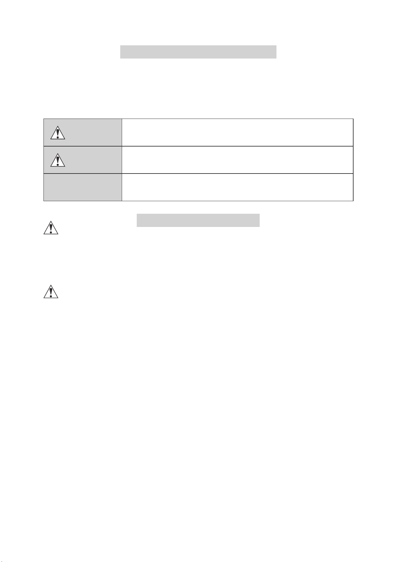
1 Part Names
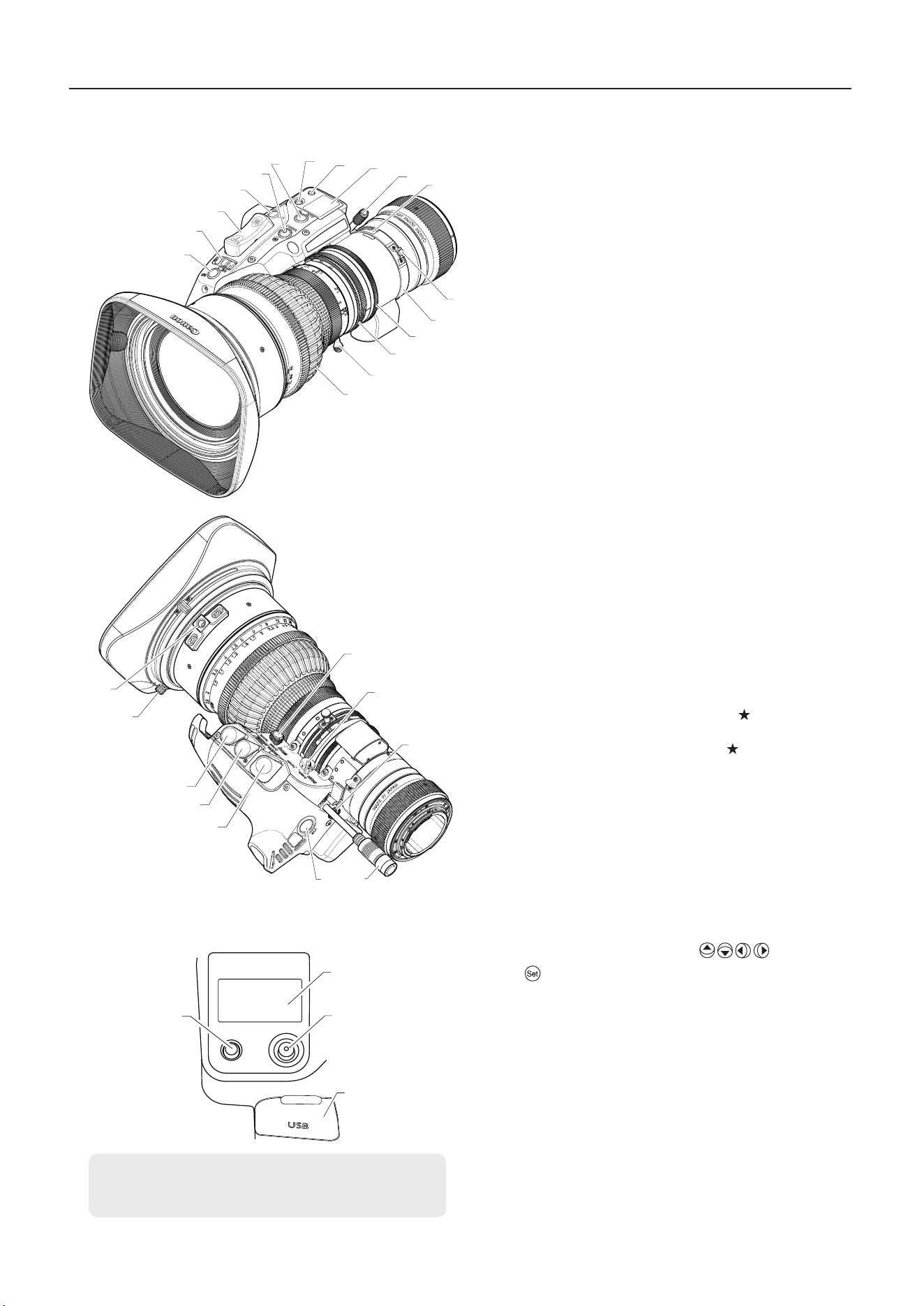
Information display
①
②
③
④
⑤
⑥
⑦
⑧
⑨
⑩
⑪
⑫
⑬
⑭
⑮
⑯
⑰
⑱
⑲
⑳
㉒㉓
㉔
㉕
★
㉑
㉖
㉔
㉔
For details, refer to the Information Display operation
manual.
⑦
⑧
⑨
㉗
① Instant auto-iris switch
② Iris A/M switch
③ Zoom rocker seesaw
④ RET switch
⑤ MEMO switch
⑥ AUX switch
⑦ Display control key
⑧ Display switch
⑨ Display
⑩ Flange-back lock screw
⑪ Flange-back adjusting ring
⑫ Macro button
⑬ Macro ring
⑭ Iris ring
⑮ Zoom ring
⑯
Zoom lever
⑰ Focus ring
⑱
Focus operation change-over knob
⑲ Zoom operation change-over knob
⑳ Extender Lever
㉑ Power/iris control cable
㉒Max. zoom speed adjustment volume
㉓ VTR switch
㉔ Remote connectors (20-pin)
Note: Virtual output only available from connector
For connecting zoom or focus control accessories equipped with a
20-pin connector. The connector labeled is also equipped with
interface functionality for virtual systems and can output zoom,
focus, and iris position signals.
㉕ Hood lock knob
㉖Lens Holder
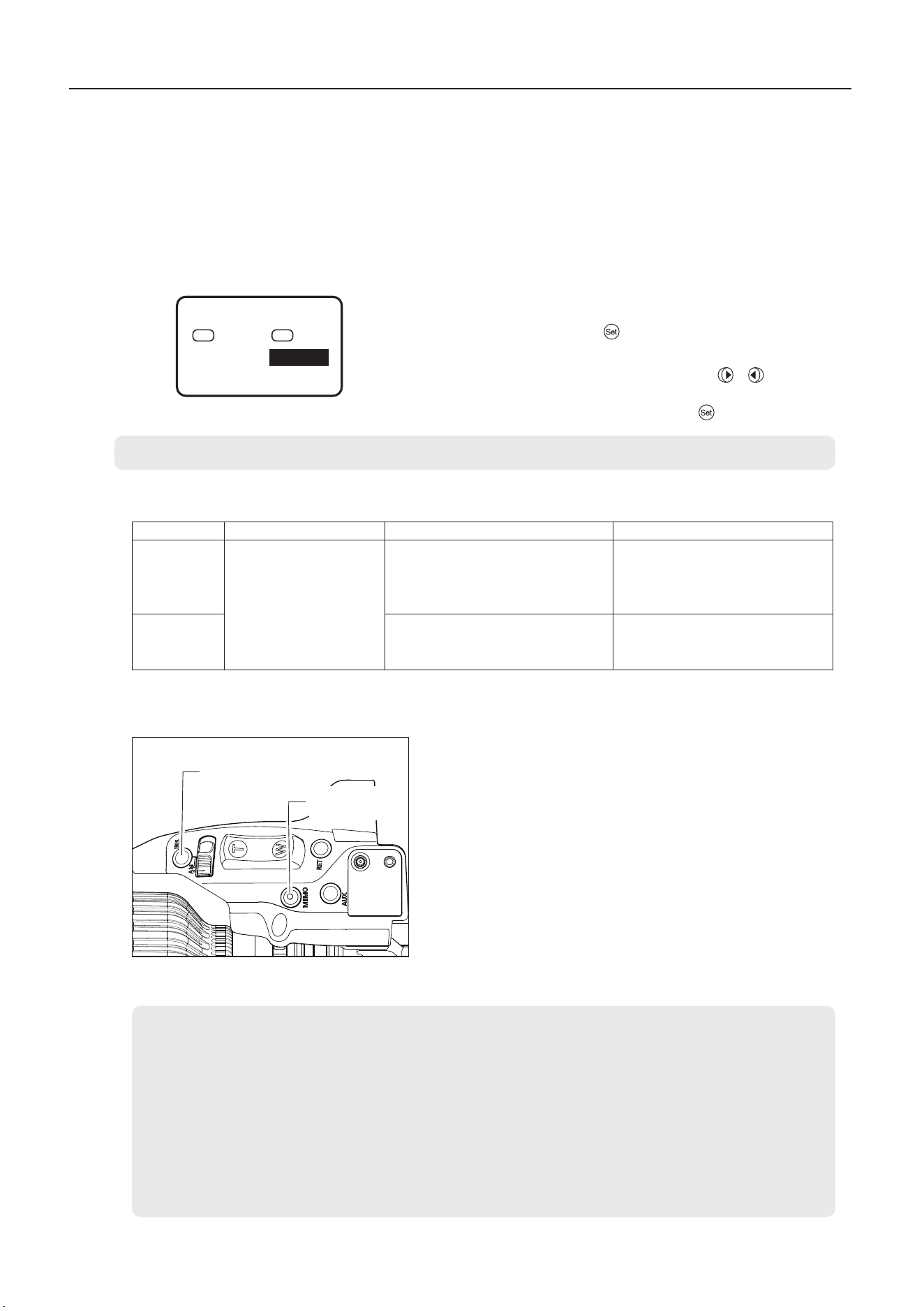
⑦ Display control key
Moves the cursor up/down/left/right ( ). Press straight
in ( ) to conrm.
⑧ Display switch
Turns the display on/o.
⑨ Display
Turns o after 2 min. without any operations.
㉗ USB port (behind cover)
Enables exporting or importing of lens setting data by
connecting a USB device (USB ash drive).
Also enables exporting of logs with data such as lens
management information, or service logs that include a record of
lens operations. For PL-mount models, lens equipment rmware
can be updated by connecting a USB ash drive containing a
rmware update le.
CN5x11
8
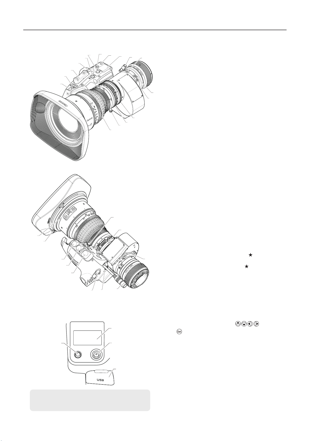
1 Part Names
Information display
①
②
③
④
⑤
⑥
⑦
⑧
⑨
⑩
⑪
⑫
⑬
⑭
⑮
⑯
⑰
⑱
⑲
⑳
㉒
㉓
㉔
㉕
㉑
★
㉓
㉓
For details, refer to the Information Display operation
manual.
⑦
⑧
⑨
㉖
① Instant auto-iris switch
② Iris A/M switch
③ Zoom rocker seesaw
④ RET switch
⑤ MEMO switch
⑥ AUX switch
⑦ Display control key
⑧ Display switch
⑨ Display
⑩ Flange-back lock screw
⑪ Flange-back adjusting ring
⑫ Macro button
⑬ Macro ring
⑭ Iris ring
⑮ Zoom ring
⑯
Zoom lever
⑰ Focus ring
⑱
Focus operation change-over knob
⑲ Zoom operation change-over knob
⑳ Max. zoom speed adjustment volume
㉑ Power/iris control cable
㉒ VTR switch
㉓ Remote connectors (20-pin)
Note: Virtual output only available from connector
For connecting zoom or focus control accessories equipped with a
20-pin connector. The connector labeled is also equipped with
interface functionality for virtual.
㉔ Hood lock knob
㉕ Lens Holder
⑦ Display control key
Moves the cursor up/down/left/right ( ). Press straight
in ( ) to conrm.
⑧ Display switch
Turns the display on/o.
⑨ Display
Turns o after 2 min. without any operations.
㉖ USB port (behind cover)
Enables exporting or importing of lens setting data by
connecting a USB device (USB ash drive).
Also enables exporting of logs with data such as lens
management information, or service logs that include a record of
lens operations. For PL-mount models, lens equipment rmware
can be updated by connecting a USB ash drive containing a
rmware update le.
CN7x17
9
NOTE
When using a
φ
19 rod, attach the supplied attachment
holder to the lens holder in advance.
2
-
1
.
Mounting the lens on a camera
2 Mounting and Connection
2 Mounting and Connection
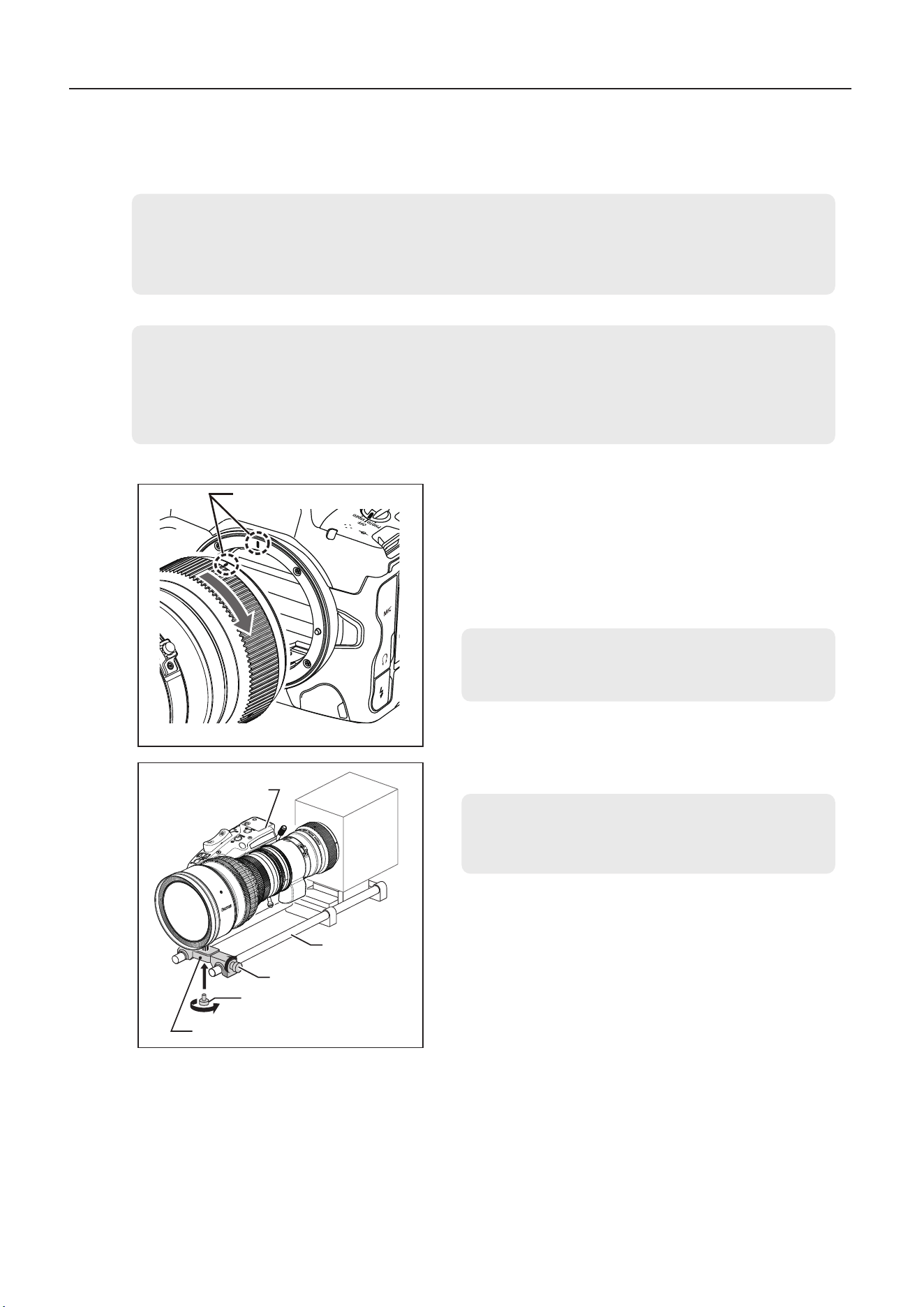
For PL mount, read the following instructions before mounting the lens.
1. The PL mount supports Cooke’s /i Technology, so make sure that the camera is set to “/i”.
2. Do not mount the lens if the camera is set to a mount communication mode other than “/i”. Doing so
could result in malfunction.
1
Attach the lens to the camera tightly so that both mounting
surfaces are in complete contact.
*
RF
mount only
Align the lens mount indexes of the lens and the camera,
and turn the lens as shown by the arrows until you hear a
click.
Lens support
Rods
Drive unit
NOTE
1.
Before mounting the lens on the camera or detaching the lens from the camera, make sure that the power
of camera and the power of supply equipment are turned o.
2.
The mounting method diers depending on the lens mounts. Refer to the operation manual for the
respective camera for the detailed information.
NOTE
If the rod interferes with the lens body or drive unit when
mounting the lens, remove the rod and then mount the lens.
2
Secure the lens holder on the lens support using the
clamping screw supplied with the lens support.
3 Fix the lens support to the rods using lens support xing
screws.
4 When the lens is mounted, connect the power/iris control
cable to a power supply equipment such as camera or ex-
ternal power supply.
Lens mount index
*RF mount only
Lens support
xing screws
Screw supplied with
the lens support
10
2-2.
Mounting the hood on the lens
2 Mounting and Connection
NOTE
1. Attach the lens cap before detaching the lens from the camera.
2. After detaching the lens, place the lens with the rear end up to prevent the lens surface and contacts from
getting scratched. If the contacts get soiled, scratched, or have ngerprints on them, corrosion or faulty
connections can result. The camera and lens may not operate properly. If the contacts get soiled or have
ngerprints on them, clean them with a soft cloth.
3. Rated voltage of the drive unit : 12 V DC
Input voltage range of the drive unit : 10 V to 17 V DC
If a battery or adapter is used, the output voltage may be higher than the rated voltage depending on the
manufacturers and therefore the above voltages must be observed strictly. If a voltage outside the input voltage
range is used, the drive unit may be damaged. And the drive unit power input has the positive and negative
polarities. Make sure to connect the power cable to the correct polarity when connecting the batteries or the
adaptors. Connecting the cable to the incorrect polarity may cause the damage to the product.
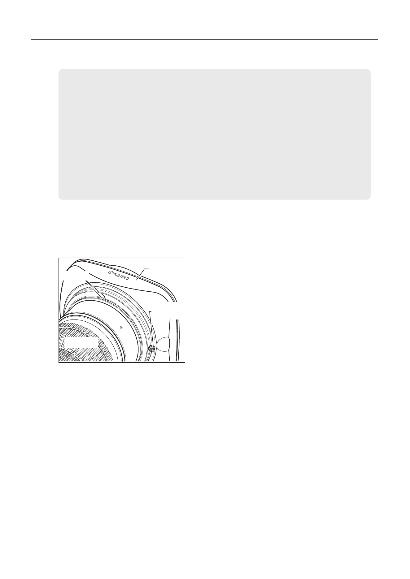
The lens is shipped with the lens cap attached. Remove the lens cap before mounting the hood.
1 Attach the hood to the front of the lens barrel.
2 Align the index marks on the hood and lens barrel.
3 Tighten the hood lock knob.
2-3. Turning the lens on
Turn on the camera, which will supply power to the lens.
Index mark
Hood
Hood lock
knob
Lens barrel

11
NOTE
1. Be sure to use the lens holder when mounting the lens on a camera. Be sure to avoid applying excessive weight to
the lens mount when the lens is mounted on a lens support..
2. Attaching a lter
A 127 mm lter can be attached to the hood.
When attaching a lter to the lens body, use the Canon CL/112 mm clear lter (hereafter refered to as the CL/112
mm).
The CL/112 mm can be used together with a 127 mm lter attached to the hood.
Using a commercially available 112 mm lter other than the CL/112 mm could interfere with the hood, making it
impossible to mount the hood properly.
2-4.
Available accessories
2 Mounting and Connection
A variety of professional camera accessories are available using
φ
15 mm and
φ
19 mm rod adaptors.
(When using a
φ
19 rod, attach the supplied attachment holder to the lens holder.)
12
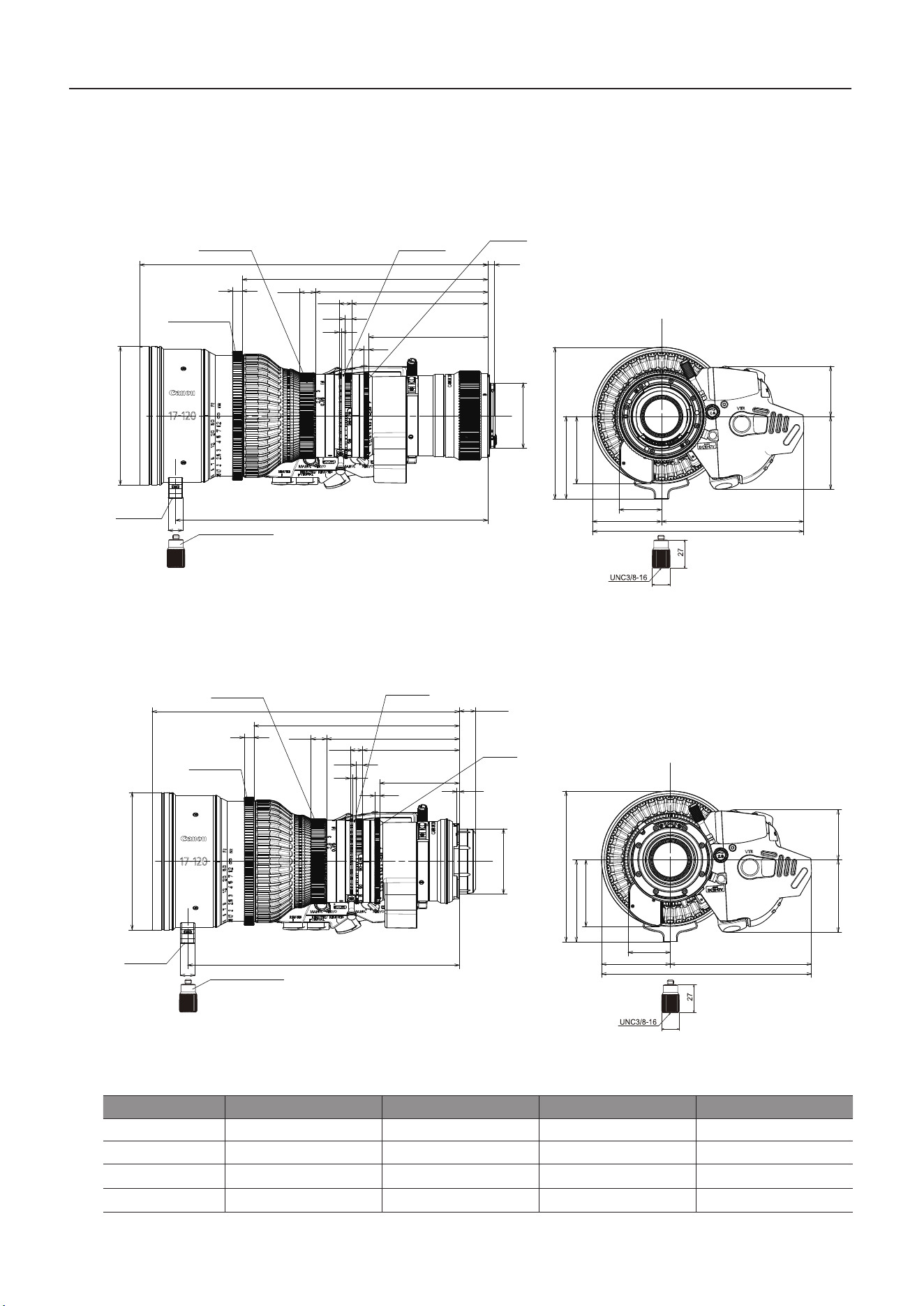
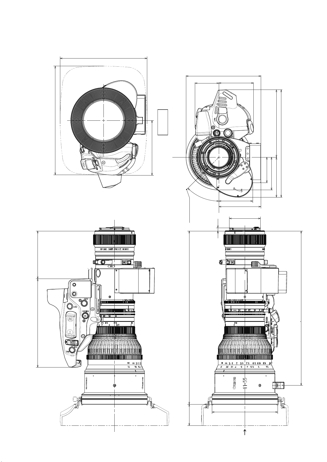
(Unit : mm)
CN5x11 IAS T/R1
(
RF mount
)
CN5x11 IAS T/P1
(
PL mount
)
Spur gear specications
Focus ring A Focus ring B Zoom ring Iris ring
Number of teeth
119 140 140 175
Module
0.8 0.5 0.5 0.4
P.C. D.
95.2 mm 70 mm 70 mm 70 mm
Angular rotation
180° 180° 93.5° 52.5°
11
72.9
58.9
60.1
41.5
129.9
44.2
56.9
69.5
117.1
186.6
301
215.2
8
13
5.5
165.5
10.3
135.7
121.6
4.1
5.6
2.1
φ114
268.3
UNC1/4-20
φ17
UNC3/8-16
27
Focus ring B
Focus ring A Zoom ring Iris ring
Attachment holder
φ54
φ17
11
UNC3/8-16
Attachment holder
UNC1/4-20
269
183.2
8
13
13.3
133.5
10.3
103.7
89.6
4.1
5.6
2.1
φ54
72.9
58.9
60.1
41.5
129.9
φ114
236.3
44.2
56.9
69.5
117.1
186.6
27
Focus ring B
Focus ring A Zoom ring
Iris ring
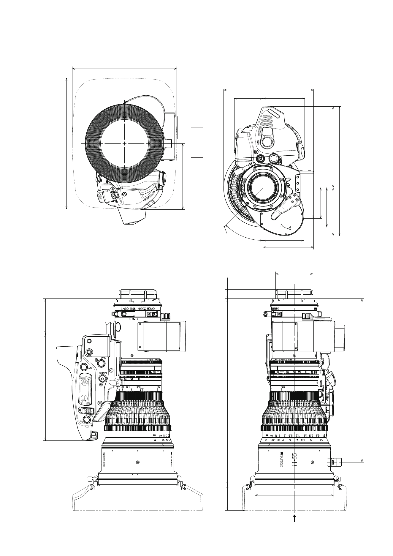
2-5.
Dimensions of parts
2 Mounting and Connection
13
(Unit : mm)
CN7x17 KAS T/R1
(
RF mount
)
CN7x17 KAS T/P1
(
PL mount
)
Spur gear specications
Focus ring A Focus ring B Zoom ring Iris ring
Number of teeth 131 140 140 175
Module 0.8 0.5 0.5 0.4
P.C. D. 104.8 mm 70 mm 70 mm 70 mm
Angular rotation 180° 180° 93.5° 52.5°
φ17
11
Focus ring B
Focus ring A
Zoom ring
Iris ring
Attachment holder
68
125
55.5
35
57
174.1
117.1
60.1
41.5
UNC1/4-20
8
170.4
110
13
5.6
4.1
66.1
13.3
254.9
2.1
80.2
10.3
225.4
φ114
φ
54
2
2 Mounting and Connection
φ17
11
8
202.4
142
13
5.6
4.1
98.1
5.5
286.9
2.1
112.2
10.3
257.4
φ114
UNC1/4-20
68
125
55.5
35
57
174.1
117.1
60.1
41.5
φ
54
Focus ring B
Focus ring A
Zoom ring
Iris ring
Attachment holder
14
1 Choose a subject at a suitable distance
(CN5x11, CN7x17 :
Approx. 1.5–3 m) as the subject. For easier adjustment,
choose a subject with sharp contrast.
2 Set the extender lever to 1x. (Only models with built-in
extender)
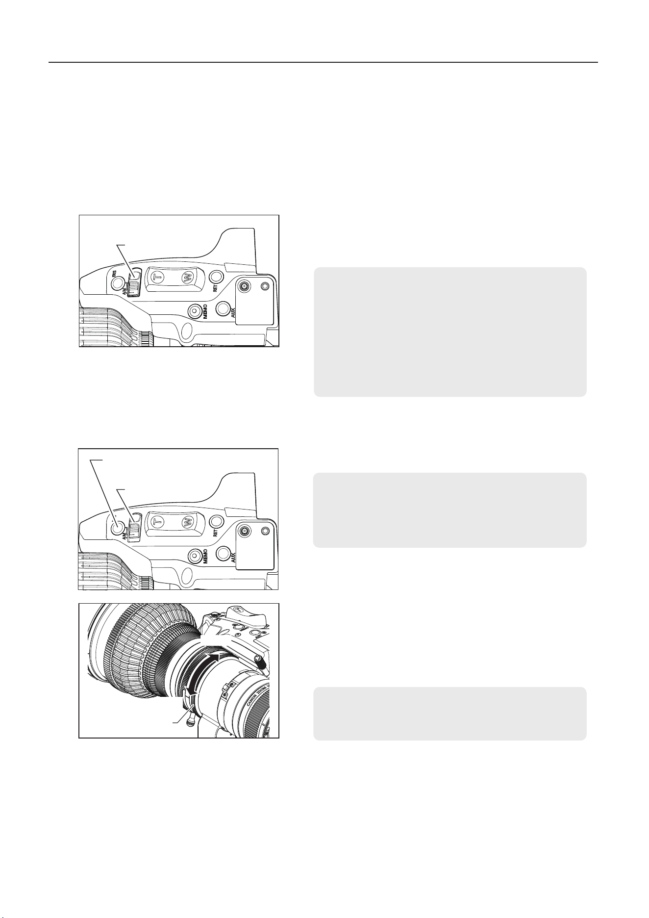
3 Turn the iris ring to maximum aperture.
4 Turn the zoom ring to zoom in all the way to the telephoto
end.
5 Turn the focus ring to bring the subject into focus.
6 Turn the zoom ring to zoom out all the way to the wide-
angle end.
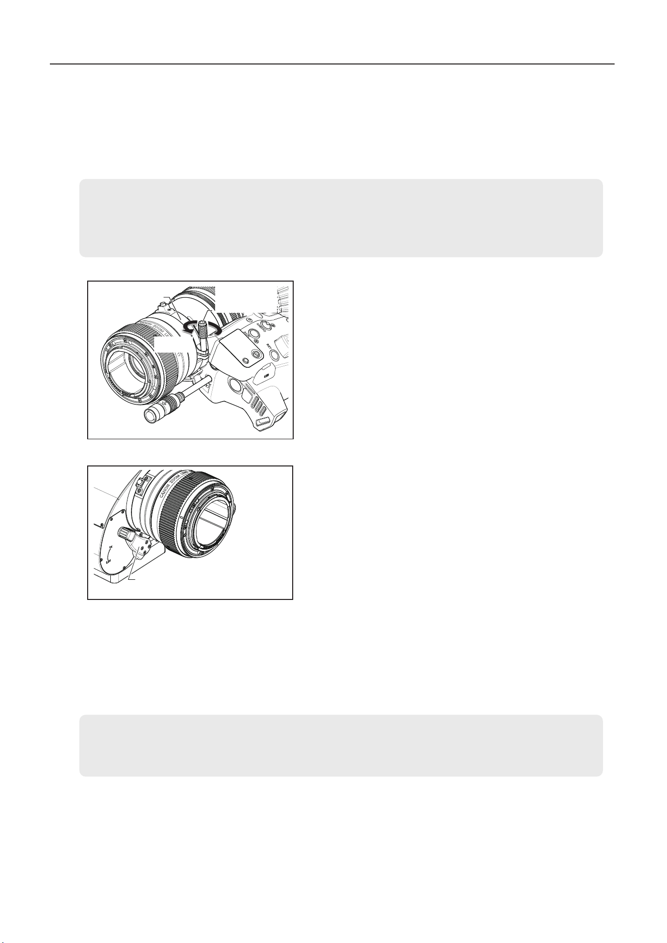
7 Loosen the ange-back lock screw, then turn the ange-
back adjusting ring to bring the subject into focus.
8 Repeat steps 4–7 a few times until the subject is in focus
at both extremes of zooming.
9 Tighten the ange-back lock screw.
3 Adjustment
3-1. Adjusting back focus
If the relationship between the image plane of the lens and the image plane of the television camera is
incorrect, the object goes out of focus when the lens is zoomed. Adjust lens back focus as follows.
3 Adjustment
3-2. Adjusting auto iris gain
Auto iris gain is adjusted using the display. Although it is correctly calibrated at the time of delivery, it can
be adjusted as needed. For instructions, see “4-3. Auto iris gain adjustment” in this manual and refer to the
Information Display operation manual.
NOTE
Set the camera auto iris mode if you will adjust gain while checking iris operation. For camera setting instructions,
refer to the camera manual.
Flange-back
adjusting ring
Flange-back
lock screw
NOTE
When adjusting back focus, turn the ange-back adjusting ring slowly as you check subject blurring.
Moving the ring greatly out of the range in focus poses a risk of scratching the drive unit surface if the ange-back
lock screw comes into contact with it.
Loosen
Extender Lever
(Only models with built-in extender)
15
4
Settings
4 Settings
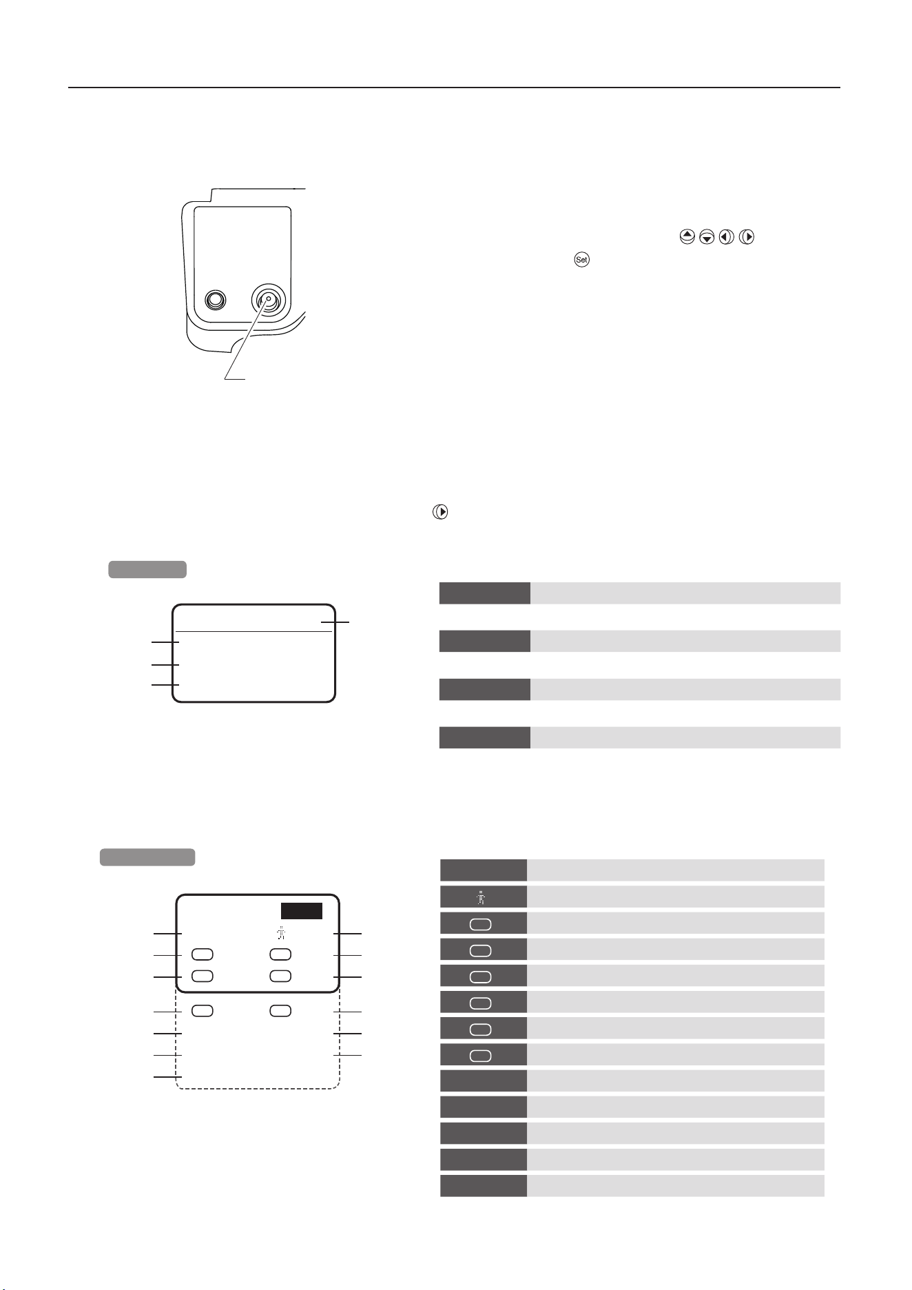
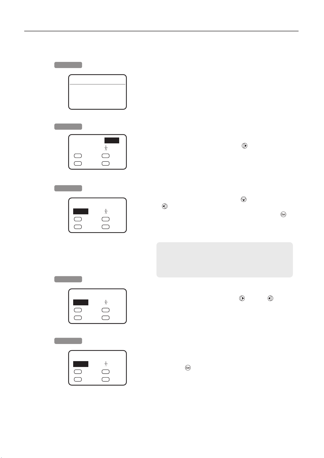
4-1. Top and Sub screen
The Top screen is the rst screen displayed after the display switch is pressed. From the Top screen, you can
access other screens to congure or check lens settings. With the cursor on the rst line of the Top screen,
you can also press the display control key right ( ) to move it to the Sub screen position and access Sub
screen.
A variety of lens settings can be congured using the information display.
Top screen
From the Sub screen, you can set and adjust settings
①
–
⑬
below.
To congure settings, press the information display
control key up, down, left, or right ( ). Press
the key straight in ( ) to conrm.
Display control key
Sub screen
Top
◀
<Sub>
▼
①
[IG] 50 [ ] 1
②
③
A
Fr1P
V
VTR
④
⑤
AM
Norm
R
RET
⑥
⑦
A1
Shtl
A2
Fr1P
⑧
⑨
[I-Tq] H [Trk] OFF
⑩
⑪
[Copy] [Z.M.]
⑫
⑬
[Adj]
①
[IG]
Auto iris gain setting
②
[ ]
User switching
③
A
AUX switch function assignment
④
V
VTR switch function assignment
⑤
AM
Iris A/M switch operation setting
⑥
R
RET switch function assignment
⑦
A1
AUX1 switch function assignment
⑧
A2
AUX2 switch function assignment
⑨
[I-Tq]
Iris torque setting
⑩
[Trk]
Zoom track on/o switching
⑪
[Copy]
User setting copying
⑫
[Z.M.]
Zoom rocker seesaw responsiveness setting
⑬
[Adj]
Automatic adjustment of the mechanical end
<Top>
▶
Sub
①
▼
②
Status
③
Setting
④
Support
①
Sub Sub screen
Lists 13 setting menus
②
Status Status screen
Lens status menu (cannot be congured)
③
Setting Setting screen
Lens setting menu
④
Support Support screen
Lens support information menu
16
4
Settings
1 Set the iris A/M switch on the drive unit to A (auto).
4-3. Auto iris gain adjustment
Although auto iris gain is correctly calibrated at the time of delivery, you can adjust the gain while checking
iris operation as follows. The auto iris gain set applies to all users.
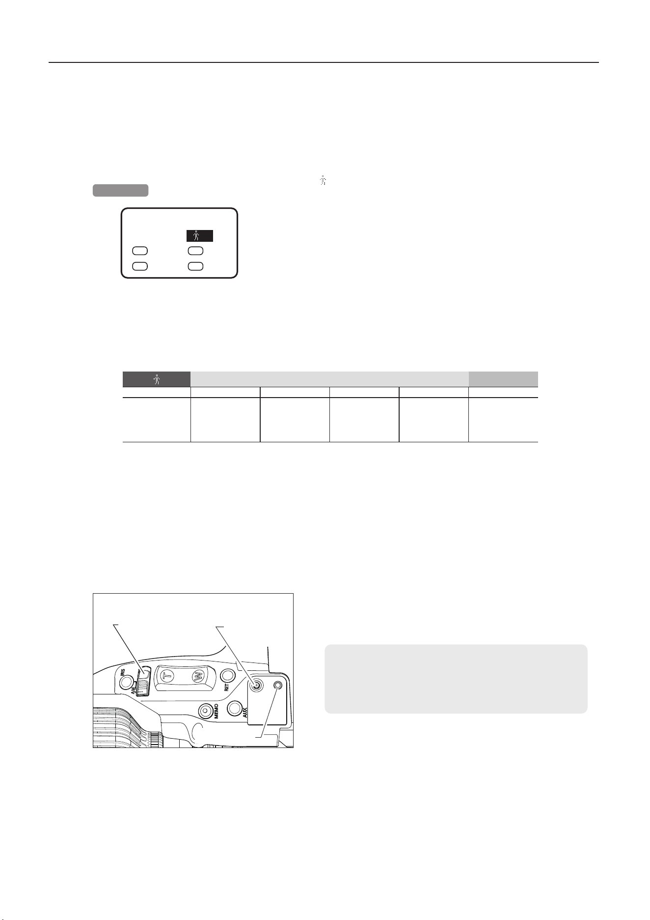
4-2. User setting
For each user, specic functions can be assigned to switches. Switch to the user to use, then assign functions
to switches.
Sub screen
[
]
User switching
You can switch users on a Sub screen. In the screenshot at
left, user 1 is the current user. The user options listed are
TEMP, 1, 2, 3, and Lock. Settings can be saved when the user
is 1, 2, or 3. Settings cannot be saved when the user is set to
TEMP. Moreover, setting the user to Lock will restrict switching
users or entering data for some settings. To switch users,
you will need to cancel the Lock setting. For Lock setting and
cancellation details, refer to the Information Display operation
manual.
NOTE
Set the camera auto iris mode if you will adjust gain while
checking iris operation. For camera setting instructions,
refer to the camera manual.
Top <Sub>
[IG] 50
◀
▲
[ ] 1
▼
A
Fr1P
V
VTR
AM
Norm
R
RET
[ ]
User Locked
Options TEMP 1 2 3 Lock
Description
Settings can be
changed
temporarily
Settings can
be saved
Settings can
be saved
Settings can
be saved
Prevents user
switching
Iris A/M switch
Display switch
Display control
key
17
5 Press the display control key right (
) or left (
) to ad-
just iris gain. You can check the current iris gain adjustment
value, which is shown to the right of [IG]. In the screenshot
at left, the iris gain adjustment value has been changed to
55. As you watch the lens iris ring, adjust to a suitable gain at
which “focus hunting” does not occur.
6 With a suitable value selected, press the display control key
straight in
( ). The cursor changes from blinking to lit, and
the iris gain value is set.
Sub screen
Sub screen
Sub screen
Sub screen
3 Press the display control key right (
) once. The cursor
moves to the Sub display position and a Sub screen is dis-
played.
4 Press the display control key down (
) once and then left
(
) once. The cursor moves to the [IG] display position. In
this position, press the display control key straight in
( ).
The cursor starts blinking at the [IG] display position.
Top <Sub>
[IG] 50
▲
▶
[ ] 1
▼
A
Fr1P
V
VTR
AM
Norm
R
RET
Top <Sub>
[IG] 55
◀▶
[ ] 1
A
Fr1P
V
VTR
AM
Norm
R
RET
Top <Sub>
[IG] 55
▲
▶
[ ] 1
▼
A
Fr1P
V
VTR
AM
Norm
R
RET
2 Press the display switch to activate the display. The Top
screen is displayed.
Top
screen
<Top>
▶
Sub
▼
Status
Setting
Support
4
Settings
NOTE
RF-mount model: [---] is displayed and this function is
disabled when the iris is controlled by a camera via RF
communication.
Top
◀
<Sub>
▼
[IG] 50 [
] 1
A
Fr1P
V
VTR
AM
Norm
R
RET
18
Top
◀
<Sub>
▼
[IG] 50 [
] 1
A
Fr1P
V
VTR
AM
Norm
R
RET
A1
Shtl
A2
Fr1P
[I-Tq] H [Trk] OFF
[Copy] [Z.M.]
[Adj]
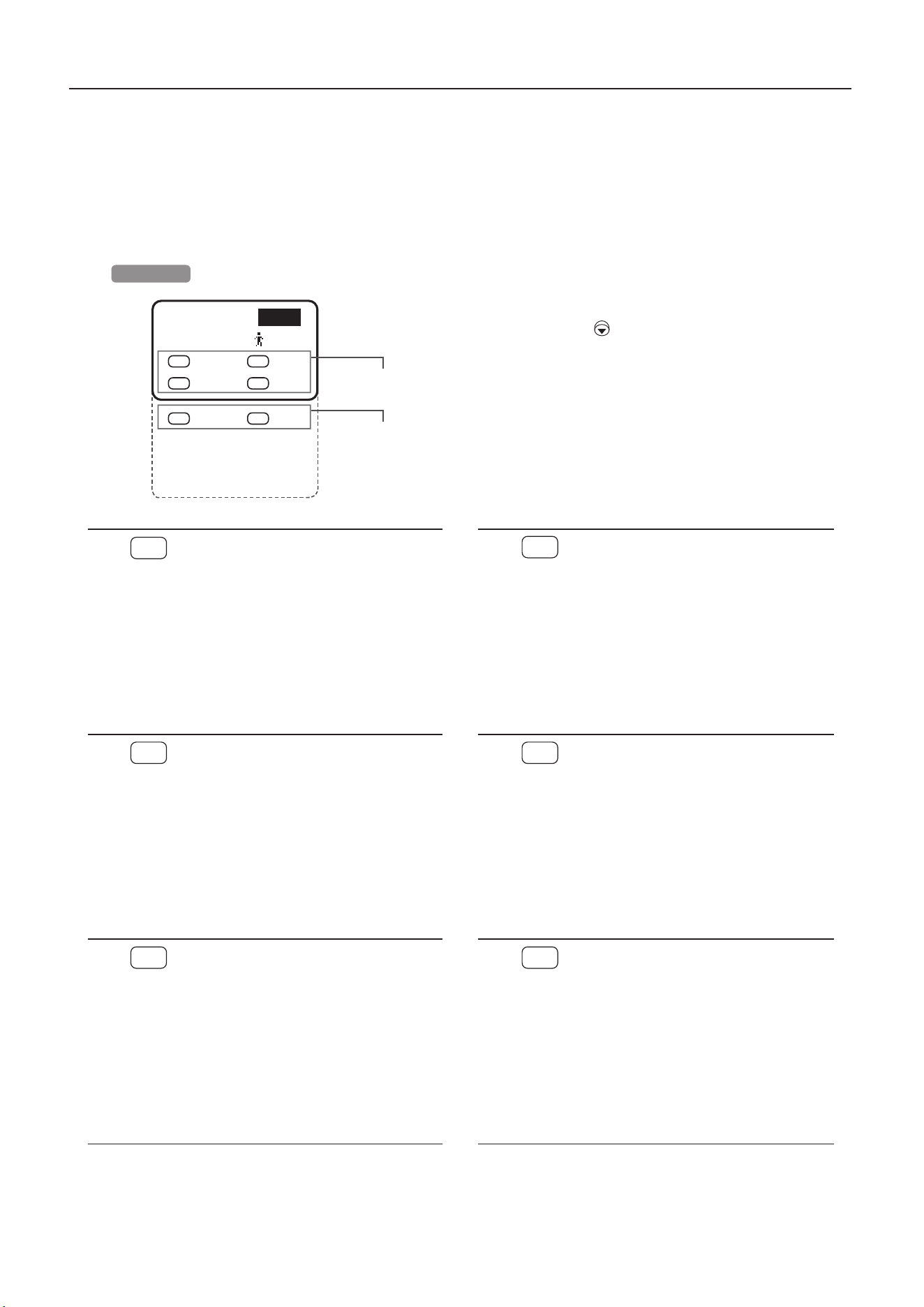
4-4. Switch function assignment
Drive unit or demand switches can be programmed to activate a function of your choice. Switch to the
relevant user before assigning functions to switches.
On the initial Sub screen, you can assign functions to four
drive unit switches. Scroll down by pressing the display
control key down ( ), and you can assign functions to
the two demand switches in the dotted outline at left, set
iris ring torque, activate/deactivate the zoom track
function, copy user settings, set zoom rocker seesaw
responsiveness and adjust the mechanical end
automatically.
Sub screen
Drive unit switches
Zoom demand
switches
A
AUX switch
By default, the drive unit AUX switch is
assigned to framing preset 1 (preset speed),
but it can be assigned to functions in Table
4-4-1.
For details, refer to “2-3 AUX switch function
assignment” in the Information Display
operation manual.
V
VTR switch
By default, the drive unit VTR switch is
assigned to VTR, but it can be assigned to
functions in Table 4-4-1.
For details, refer to “2-4 VTR switch function
assignment” in the Information Display
operation manual.
AM
Iris A/M switch
Enables you to change drive unit iris A/M
switch operation. By default, it is set to operate
normally, but it can be assigned to functions in
Table 4-4-2.
For details, refer to “2-5 Iris A/M switch
operation setting” in the Information Display
operation manual.
R
RET switch
By default, the drive unit RET switch is
assigned to RET, but it can be assigned to
functions in Table 4-4-1.
For details, refer to “2-6 RET switch function
assignment” in the Information Display
operation manual.
A 1
AUX1 switch
By default, the AUX1 switch for ZSD series
zoom demands is assigned to shuttle shot, but
it can be assigned to functions in Table 4-4-1.
For details, refer to “2-7 AUX1 switch function
assignment” in the Information Display
operation manual.
A 2
AUX2 switch
By default, the AUX2 switch for ZSD series
zoom demands is assigned to framing preset
1 (preset speed), but it can be assigned to
functions in Table 4-4-1.
For details, refer to “2-8 AUX2 switch function
assignment” in the Information Display
operation manual.
4
Settings

19
For details, refer to the Information Display operation manual.
Options
VTR
RET
RET2
*1
RET3
*1
RET4
*1
RET5
*1
RET6
*1
RET7
*1
RET8
*1
Description
VTR RET RET2 RET3 RET4 RET5 RET6 RET7 RET8
Options
Fr1P Fr1F Fr2P Fr2F Sped Shtl
AF
*2
NON
*3
Description
Framing
preset 1
(preset speed)
Framing
preset 1
(max. speed)
Framing
preset 2
(preset speed)
Framing
preset 2
(max. speed)
Speed
preset
Shuttle shot
Auto focus
No function
*1 : RET2–8 (RET2, RET3, RET4, RET5, RET6, RET7, and RET8) are listed and available when the setting described in “4-15 RET2–8
on/o switching” in the Information Display operation manual is set to on.
*2 : RF-mount model: [AF] is displayed and this option can be selected.
AF functionality is only available with some cameras. For details, refer to the camera manual.
*3 : Can be assigned to AUX, AUX1, or AUX2 switches.
Options
Norm Reve Auto
*4
Manu
*4
Description
Normal operation
A : Auto
M : Manual
Reverse operation
A : Manual
M : Auto
Auto only
A : Auto
M : Auto
Manual only
A : Manual
M : Manual
4-4-1. Table of switch function assignment
4-4-2. Table of iris A/M switch operation settings
4 Settings
*4 : Setting operation to Auto or Manu enables the same iris operation regardless of how the iris A/M switch is set.
20
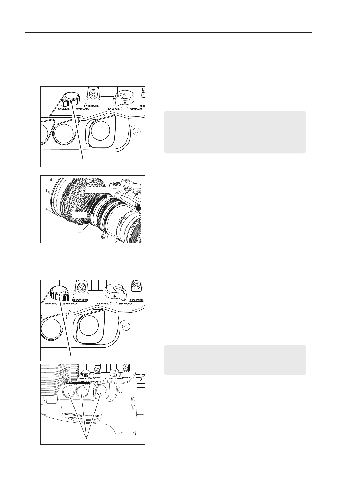
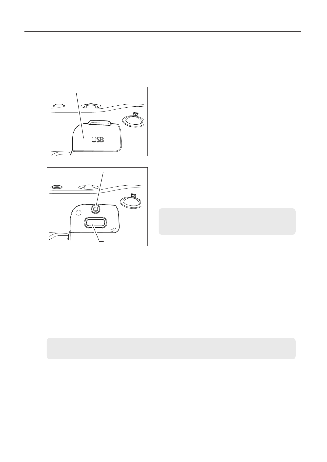
5-1-2.
Servo zooming
The built-in motor in the drive unit can also be used to zoom.
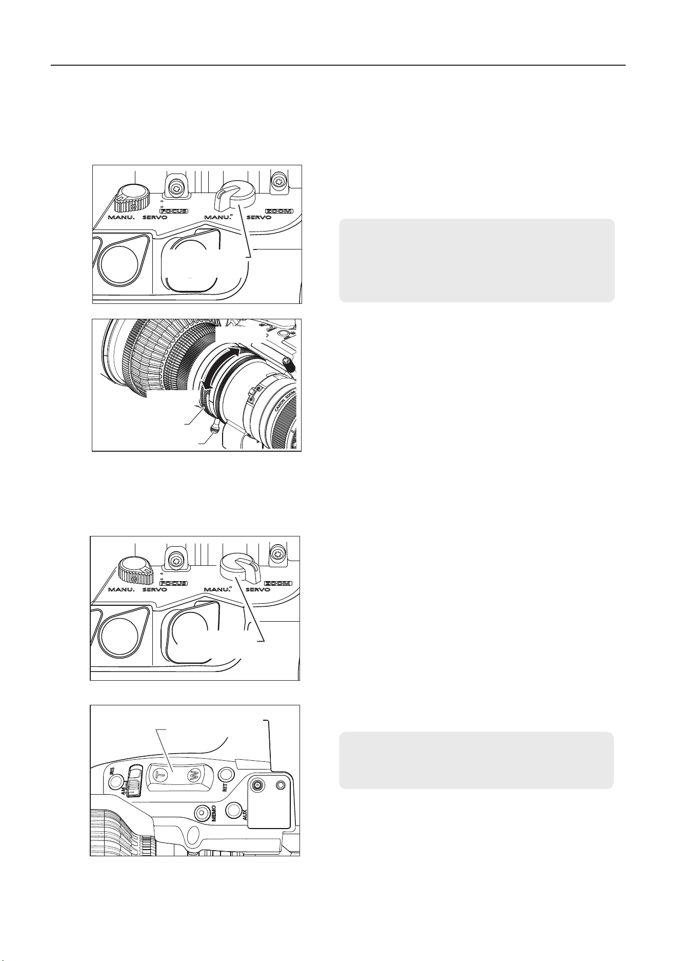
1 Set the zoom operation change-over knob to the MANU.
position.
5 Control and Shooting
5-1. Zooming
5-1-1. Manual zooming
1 Set the zoom operation change-over knob to the SERVO
position.
2 To zoom, press the zoom rocker seesaw. Zoom speed
changes in response to how far down you press the switch.
The further you press the switch, the faster the lens zooms.
5 Control and Shooting
NOTE
Only manual zooming or focusing is available while the lens
is reading from or writing to a USB device (USB ash drive).
Zoom operation
change-over knob
Zoom ring
NOTE
The zoom operation change-over knob must be set to the
MANU. position before manual zooming.
Forcing the lens to zoom manually with the knob set to
SERVO may cause damage.
2 To zoom, turn the zoom ring or zoom lever.
Wide-angle
Telephoto
Zoom lever
Zoom operation
change-over knob
Zoom rocker seesaw
21
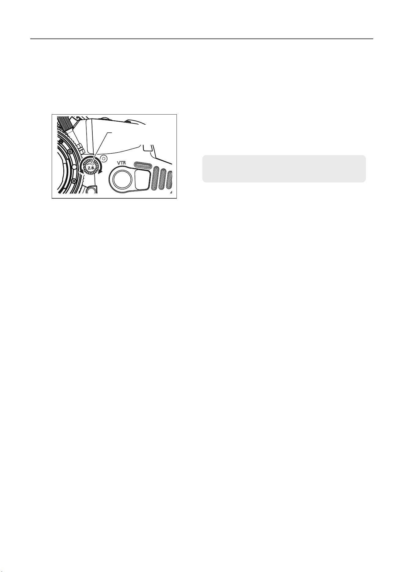
5-1-3. Adjusting maximum zoom speed
The maximum speed of zoom when the zoom rocker seesaw is pressed can be adjusted with the max.
zoom speed adjusting volume.
This setting can also be set from the information display. For
details, refer to the Information Display operation manual.
1 To increase the maximum speed, turn the max. zoom speed
adjustment volume clockwise, and to decrease it, turn the vol-
ume counterclockwise.
5 Control and Shooting
Max. zoom speed
adjustment volume
22
5-1-4. Zoom track function (servo only)
By dening your preferred zoom control range (zoom track), you can set virtual limits at the telephoto and wide-angle
ends. The zoom track function must be activated before you can use it.
A
:
Switching ON/OFF from the information display
1 Press the display switch to activate the display.
2
Use the display control key to move the cursor to [Trk], then
press the key straight in ( ). [Trk] and the current setting now
blink on the display.
3 Press the display control key right or left ( / ) to switch
between on and o.
4
Press the display control key straight in (
) to conrm.
For detailed instructions, refer to the Information Display operation manual.
NOTE
1. If you will set dierent zoom track positions, servo zooming cannot be used to move current zooming end
points closer to the mechanical limit. In this case, deactivate the zoom track function and do one of the
following.
• Use the zoom rocker seesaw to zoom.
• Zoom manually.
2. Up to two zoom track positions can be set (for the telephoto and wide-angle ends), but both positions
cannot be set on the same side of the center of the lens zoom range.
(In this case, the position set most recently is stored as the zoom track position for that end.)
5 Control and Shooting
B
:
Switching ON/OFF with switch operations
Selection method Operation How to ascertain the selection
To set the
function to
ON
Hold down the MEMO
switch and Instant
auto-iris switch
simultaneously for at
least 3 seconds.
The zoom control range is xed to
the zoom range set last. (If there is
no previous setting, it is set to the
mechanical end.)
Automatic zooming from current
zoom position to the closer of the
two set positions.
To set the
function to
OFF
The zoom range is set to the
mechanical end.
Automatic zooming from current
zoom position to the closer of
the two mechanical ends.
Setting zoom track positions
Activate the zoom track function before setting the positions.
1 Zoom in or out to a position at one end of the zoom track you
will set.
2 With the zoom still at this position, press and hold the Memo
switch, then press the instant auto-iris switch. Zoom positions
at the telephoto side are stored as the telephoto end of the
zoom track, and positions at the wide-angle side are stored
as the wide-angle end.
3 Repeat steps 1–2 to set both the telephoto and wide-angle
end. Otherwise, you can set only one end, if you prefer. To
change the setting, follow steps 1–3. (Newly set positions
overwrite any stored settings.)
Top <Sub>
A1
Shtl
A2
Fr1P
[I-Tq] H
◀
▲
[Trk] OFF
▼
[Copy] [Z.M.]
Instant auto-iris switch
Memo (memory)
switch
23
NOTE
Stored zoom speed also applies to framing presets.
5-1-6. Speed preset (servo only)
Using this function, you can zoom at your preset zoom speed at any time. Speed preset (Sped) must be
assigned to the drive unit VTR, RET, or AUX switch or the zoom demand AUX1 or AUX2 switch. Descrip-
tions in this manual are based on the speed preset (Sped) being assigned to the VTR switch.
NOTE
1. Positions set for this function are stored separately
from positions set as framing presets (described later).
Positions you specify are also retained even after the
power is turned o.
2. Shtl switch operations take precedence over zoom
rocker seesaw operations, which have no eect while
the Shtl switch is pressed.
Storing a shuttle shot position
Shuttle shot must be assigned to the drive unit VTR, RET, or AUX switch or the zoom demand AUX1 or
AUX2 switch. Descriptions in this manual are based on shuttle shot (Shtl) being assigned to the VTR
switch.
5-1-5. Shuttle shot (servo only)
Using this function, you can switch between the current zoom position and a preset position at the maxi-
mum speed.
Pressing
and
holding the
Shtl switch
5 Control and Shooting
1 Zoom in or out to a position to set. With the zoom still at this
position, press and hold the Memo (memory) switch, then
press the VTR switch (as assigned to Shtl).
Storing a zoom speed and direction
1 Press and hold the Memo (memory) switch while using the
zoom rocker seesaw to zoom at the speed and in the direc-
tion (toward the telephoto or wide-angle end) to store.
VTR switch
Memo (memory) switch
Zoom rocker seesaw
VTR switch
Memo (memory) switch
Zoom rocker seesaw
Releasing
the Shtl
switch
At max.
speed
At max.
speed
Current zoom position Stored shuttle position Original zoom position
24
Using speed presets
NOTE
You can store up to two framing presets, identied as Frame1 and Frame2. Descriptions on the following pages
only discuss Frame1. Also note that the Frame1 preset is abbreviated as Fr1P.
5-1-7. Framing preset (servo only)
Three types of framing presets are available, as follows.
[
Zoom
]
:
Conveniently reproduces a predetermined angle of view and speed of movement (zooming speed).
[
Focus
]
:
Conveniently reproduces predetermined focusing.
[
Z + F
]
:
Conveniently reproduces the speed of movement (focusing and zooming speed) for predetermined
focusing and angle of view.
5 Control and Shooting
To switch between framing preset settings, use the Preset screen
of the information display. The Frame1 setting can be changed to
Zoom, Focus, or Z+F.
<Preset>
▲
Frame1:
◀
Zoom
▶
▼
Frame2: Zoom
Z-speed: 800
1 Press the VTR switch (assigned to Sped) to start zooming at
the stored speed and in that direction (toward the telephoto
or wide-angle end). Zooming stops at the end of the range.
Canceling speed preset movement
Speed preset movement can be canceled in any of the following ways.
1
)
Once again, press the switch assigned to Sped.
2
)
Use either the zoom rocker seesaw or the switch assigned to speed (Shtl) or framing presets (Fr1P/Fr2P/
Fr1F/Fr2F).
Selecting the speed for moving to stored framing positions
To select the speed of movement to the framing position, use the switch assigned to Fr1P or Fr1F. For instruc-
tions on assigning switches, see “4-4 Switch function assignment” or refer to the Information Display operation
manual.
• Fr1P: Option for moving at the preset speed (default for AUX switch)
• Fr1F: Option for moving at maximum speed (fast)
Frame preset
control
Control content
Movement speed setting
Fr1P, Fr2P (speed settable) Fr1F, Fr2F (maximum speed)
Zoom
Zoom operation
control
The zoom moves at the preset speed.
The zoom moves at the maximum
speed.
Focus
Focus operation
control
The focus moves at maximum speed.*1 The focus moves at maximum speed.
Z+F
Zoom + focus
operation control
The zoom and focus move at the preset
speeds.*2
The zoom and focus move at the
maximum speed.
*1: Focus speed is xed at maximum speed.
*2: The zoom and focus are controlled in such a way that they start and stop simultaneously.*
VTR switch
Memo (memory) switch
Zoom rocker seesaw

25
NOTE
Descriptions in this manual are based on Fr1P being assigned to the AUX switch. Note that if this function is assigned
to a dierent switch, actual switch conditions will dier from the gures.
NOTE
Framing positions are stored separately from shuttle shot
positions. Positions you specify are also retained even after
the power is turned o.
[Zoom], [Focus], and [Z+F] framing preset settings
Moving to stored framing positions
Press the AUX switch (assigned to Fr1P) to start moving to the stored framing position at your selected speed.
Movement stops at the stored framing position.
Canceling movement to stored framing positions, or switching to other operations
Do any of the following to cancel movement to stored framing positions.
Canceling zoom framing preset operations in progress, or switching to other operations
• Once again, press the switch assigned to Fr1P.
• Use the zoom rocker seesaw.
• Use the switch assigned to Shtl.
Canceling focus framing preset or zooming and focusing preset operations in progress, or switching to other
operations
• Use a connected focus demand.
(Movement to stored positions stops, and the lens moves as directed by the focus demand.)
5 Control and Shooting
Storing framing positions
1 Zoom in or out to a position to set, and focus as needed. At
this position, press and hold the Memo (memory) switch,
then press the AUX switch (as assigned to Fr1P).
Memo (memory) switch
Zoom rocker
Seesaw
AUX switch
26
2 Turn the focus ring to bring a subject that is near or far into
focus.
5 Control and Shooting
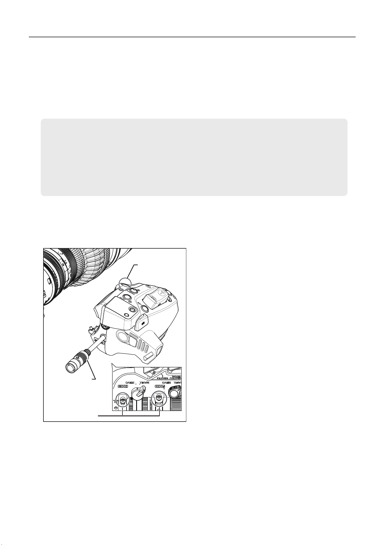
5-2-2. Servo focusing
1 Set the focus operation change-over knob to the SERVO
position.
2 Connect a focus demand or other accessory to the remote
connectors. For instructions on connection, refer to the
accessory manual.
NOTE
The focus operation change-over knob must be set to the
MANU. position before manual focusing.
Turning the focus ring by force with the knob set to SERVO
may cause damage.
1 Set the focus operation change-over knob to the MANU. po-
sition.
5-2. Focusing
5-2-1. Manual focusing
Focus operation change-
over knob
Remote connectors
Focus operation change-over
knob
Focus ring
Innity
Close range
NOTE
Only manual zooming or focusing is available while the lens
is reading from or writing to a USB device (USB ash drive).
27
1 Set the iris A/M switch to M (manual).
2 Turn the lens iris ring to perform iris operations.
NOTE
The automatic iris operation may not be performed depending
on the types of cameras.
3 For as long as you hold down the instant auto-iris switch in
manual iris mode, the mode changes to automatic.
5 Control and Shooting
NOTE
1. The automatic iris operation may not be performed
depending on the types of cameras.
2. This setting can be congured and adjusted from the
information display. For details, see “4-3. Auto iris gain
adjustment” in this manual and refer to the Information
Display operation manual.
5-3-1. Automatic iris operation
5-3. Iris operations
You can switch between auto and manual mode with the iris A/M switch. Operation of the iris A/M switch
can be congured on the display. Descriptions in this manual are based on operation with the iris A/M
switch set to [Norm].
5-3-2. Manual iris operation
1 Set the iris A/M switch to A (auto). Iris operations are per-
formed automatically, as controlled by the camera, to keep
the video signal level constant.
Instant auto-iris switch
Iris ring
Iris A/M switch
NOTE
The iris A/M switch must be set to M before you operate iris
manually. Forcing the lens to perform manual iris operations
when it is set to automatic mode may damage it.
Iris A/M switch
Closed
Open
28
5 Control and Shooting
NOTE
Macro operations are also possible when zoomed to a position
other than the wide-angle end, but this will increase the subject
distance.
1 Manually or with servo, zoom to the wide-angle end.
2 Press the macro button to unlock it, then turn the macro ring
to bring the subject into focus.
5-5. Macro operations
This mode is used for shooting small subjects at closer range than the normal minimum object distance.
At the macro position and the wide-angle end, close-ups can be as close as CN5x11:4 cm, CN7x17:10
cm from subjects.
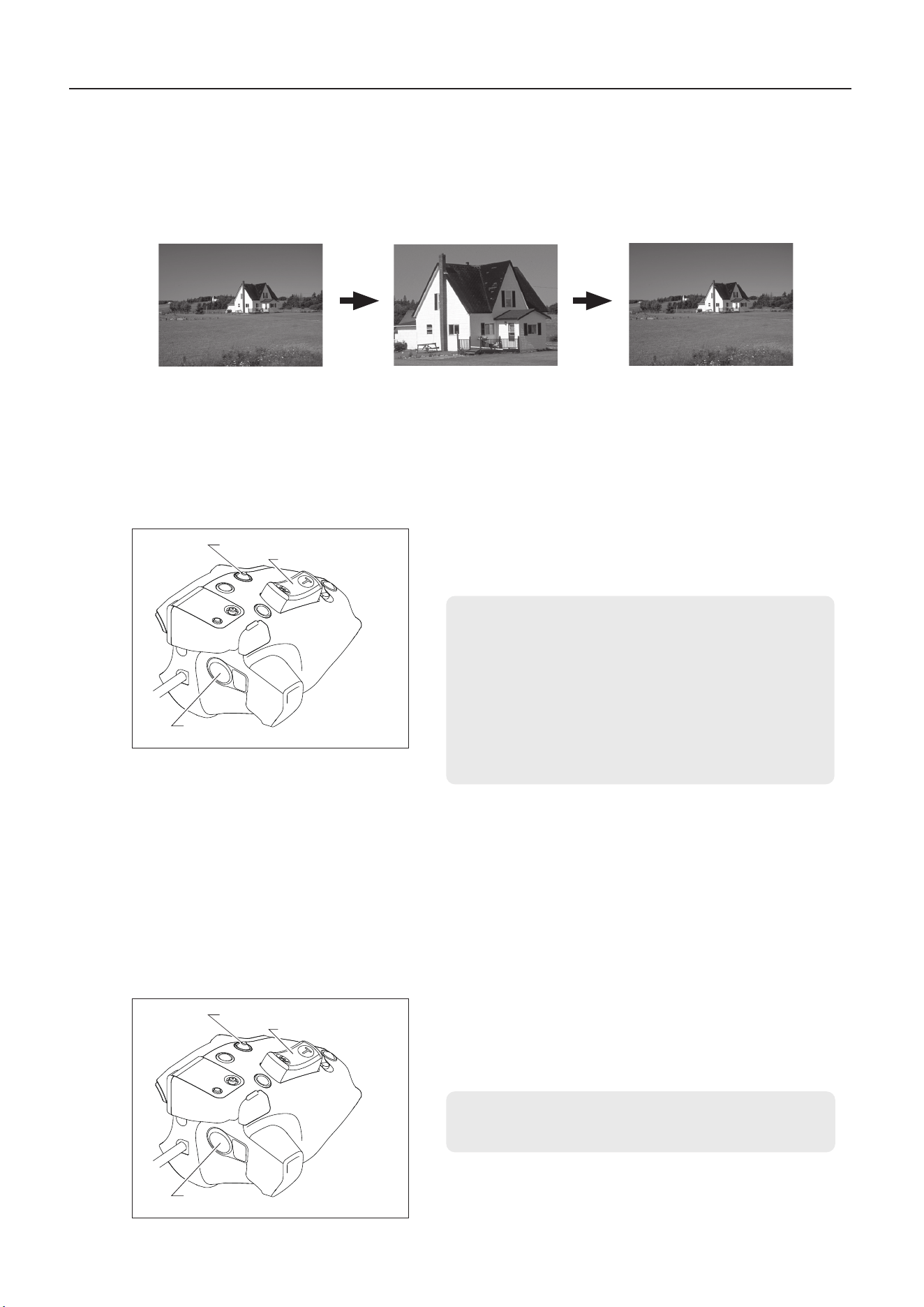
Multi-point focus shooting
Macro button
Macro ring
As a technique that relies solely on zooming to shift the focal point within the same scene, multi-point focus shooting
employs a characteristic of macro shooting – specically, zooming changes both the focal length and the focal point.
To use this technique, shoot as follows.
1 Zoom in to a distant subject and bring it into focus by focusing as usual.
2 Zoom out to a near subject and bring it into focus with the macro ring.
3 Leaving the macro button unchanged from step 2, zoom in to the distant subject again and bring it into focus again
by focusing as usual.
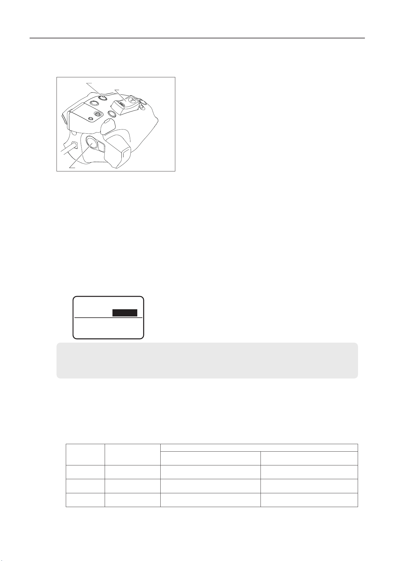
5-4. Extender operations
(Only models with built-in extender)
Extender Lever
(Only models with built-in extender)
The lens with built-in extender has the built-in 1.5× ex-
tender.
Use the extender lever to switch between 1× and 1.5×.
NOTE
When the extender is used, note that the light quantity may
decrease by the zoom ratio depending on the iris correction
setting.

29
6 USB Operations
6-1. USB Using the USB port
6-1-1. USB USB port specifications
The following functions are available when a USB device (USB flash drive) is in the drive unit USB port.
Prepare a USB flash drive to use in advance.
1. Updating lens rmware (PL-mount model*)
You can update the rmware as needed. When rmware updates are available, you can download
the latest version from the following Canon's website.
*RF-mount model rmware updates are performed from the camera using an SD card. For details, visit the following
support page.
https://cam.start.canon/
2. Exporting and importing user settings
Settings for each user can be exported to a USB ash drive and imported on other equipment to
use the same settings on that equipment.
3. Exporting lens management information or service logs
Also using a USB ash drive, you can export logs with the model name, serial number, and other
lens management information, as well as service logs that include a record of lens operations. Use
this information to manage your equipment or when requesting service.
NOTE
Only manual zooming or focusing is available while the lens is reading from or writing to a USB ash drive.
Reading or writing via USB should be done when the lens is not servo zooming or focusing.
6-1-2. Connecting to a USB host
The following functions are available when a USB host (computer) is connected to the drive unit
USB port. Prepare a computer to use as a USB host in advance.
6-1-3. USB port specications
Specications of the drive unit USB port are as follows.
Port format: USB Type-C
®
[Data rate: Full-Speed (12 Mbps)]
USB Type-C
®
and USB-C
®
are registered trademarks of USB Implementers Forum.
6 USB Operations
For details, refer to the Information Display operation manual.
1. Browsing lens management information
When the lens is connected to a computer via USB, the computer recognizes it as a USB mass
storage device where multiple text les are stored. The text les contain management information
such as the lens model name and serial number. Use the information in the text les to manage
your equipment or when requesting service. For text le details, refer to the readme.txt le stored
on the lens.
30
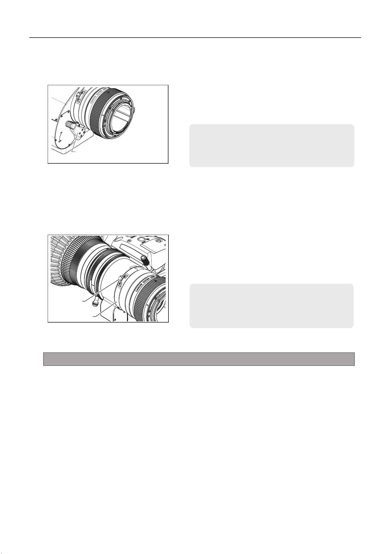
6-1-4. Preventing cable disconnection
You can use a single screw USB Type-C locking cable to prevent disconnection.
6-2. USB device specications
Specications of USB ash drives used with the drive unit USB port are as follows.
Port format: USB Type-C
®
[Data rate: Full-Speed (12 Mbps)]
Format: FAT16 or FAT32
Capacity: 32 GB recommended (formatted as FAT32)
USB Type-C
®
and USB-C
®
are registered trademarks of USB Implementers Forum.
Screw hole
Cover
1 Open the cover.
2 Connect the cable to the USB port.
3 Insert the screw for the connected cable in the screw hole and
tighten it.
NOTE
To protect contacts in the port from dust and water, keep
the cover closed when the USB port is not in use.
USB port
NOTE
Some USB ash drives may not be recognized when connected to the USB port. Check before use.
6-3. USB host specications
Specications of computers connected to the drive unit USB port are as follows.
USB device class: Compatible with USB mass storage class
Format: Capable of reading FAT16 volumes
6 USB Operations
31
7 How to attach and detach the drive unit
This product is structured so that the drive unit can be separated from the lens body. If it is used as a manual
lens, detach the drive unit while referring to Section 7-1. If the drive unit is mounted again, mount it while
referring to Section 7-2.
7 How to attach and detach the drive unit
7-1. How to detach the drive unit
1 Turn the camera and the lens power o.
2 Disconnect the power/iris control cable.
3 Detach the lens body from the camera.
4 Remove the three drive unit xing screws.
Drive unit
xing screws
Drive unit
xing screws
Power/iris
control cable
NOTE
• Take care not to damage the drive unit cover when removing the drive unit xing screws.
• Use a Phillips screwdriver with a shaft diameter of 4 mm or less to remove the drive unit xing screws.
• When the lens is tilted, the zoom ring may turn and the zoom position may change. To retain the zoom position when
the lens is tilted, mount a cinema operation accessory with adjustable torque and with a pitch of 0.5.
• If the drive unit is removed, the iris ring may turn and the iris position may change. To retain the iris position, mount a
cinema operation accessory with adjustable torque and with a pitch of 0.4 on the iris ring. For details on the operation
accessory with a pitch of 0.4, contact your Canon sales representative or dealer.
32
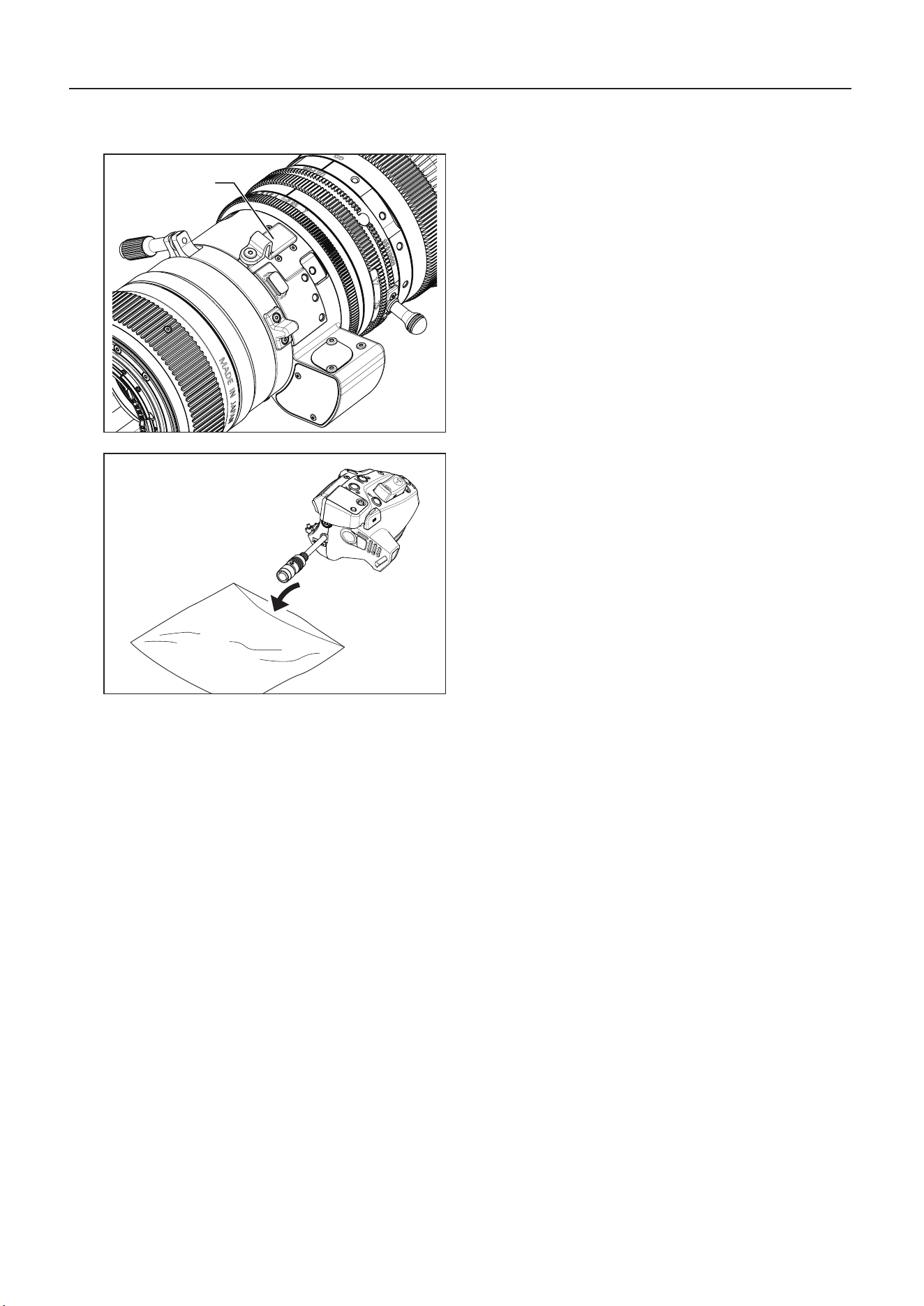
5 Place the cap on the contact of the lens body.
6 Place the detached drive unit into the included drive unit
storage bag.
7 How to attach and detach the drive unit
Cap
33
NOTE
If the serial numbers do not match, malfunction may
occur.
NOTE
If the drive unit is xed when there is a foreign material
in a screw hole, the lens body may be damaged.
NOTE
Never use screws other than the drive unit fixing
screws.
7-2. How to attach the drive unit
xxxxxxxx
xxxxxxxx
NOTE
If a drive unit xing screw is damaged or lost, use a spare one.
For additional drive unit xing screws, please contact your Canon sales representative or dealer.
7 How to attach and detach the drive unit
Connector
Positioning
pin
Serial number
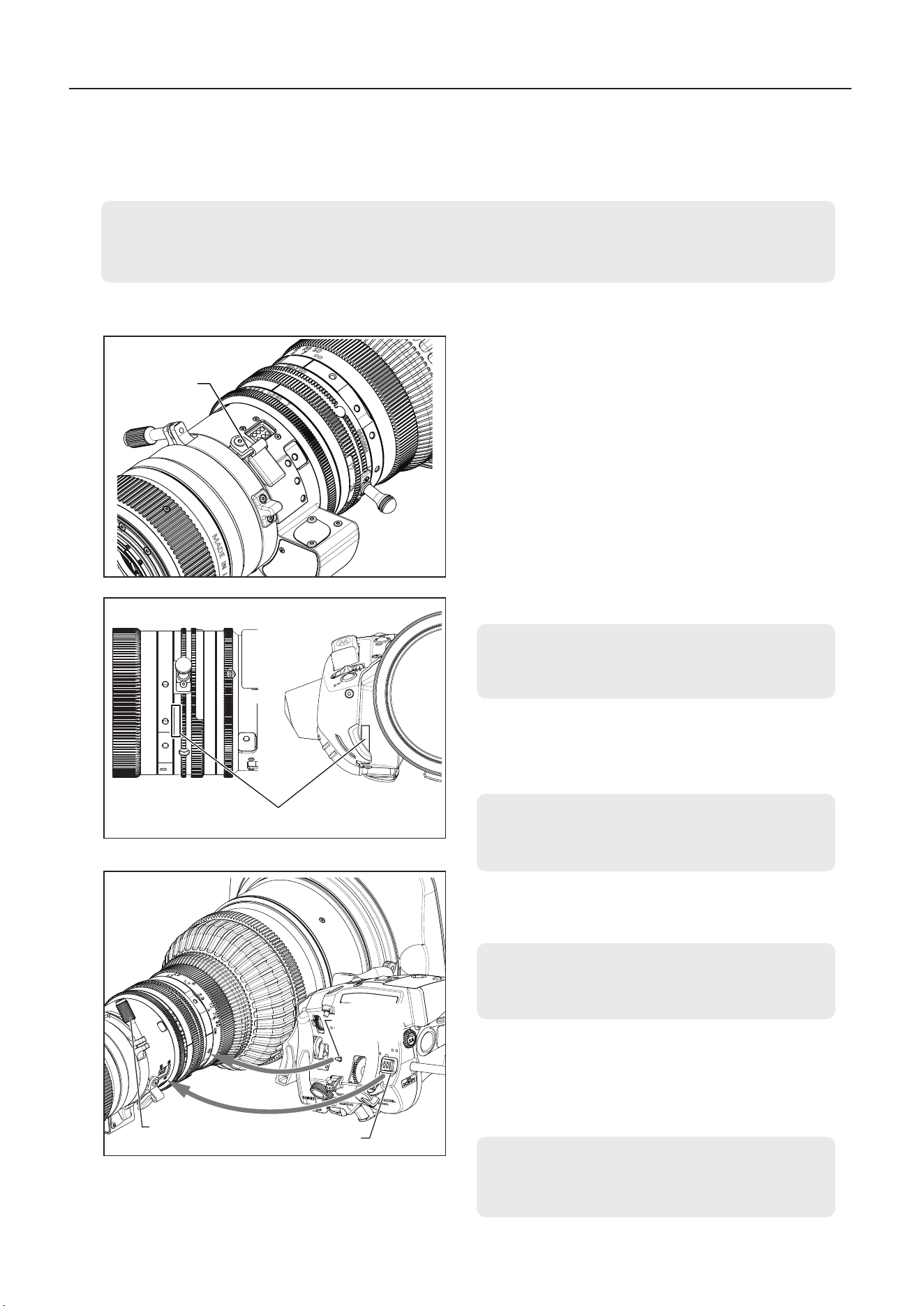
1 Remove the lens contact cap and secure it on the pro-
trusion on the lens.
2 Check that the serial numbers of the lens body and the
drive unit match.
Cap
3 Check that there are no foreign matters in the three drive
unit xing screw holes in the lens body.
4 Make sure the ange-back lock screw is in a position out
of contact with the drive unit.
NOTE
If the ange-back lock screw comes into contact with
the drive unit, it may scratch the surface.
5 Using the drive unit positioning pin as a guide, insert the
connector, and while holding the drive unit against the
lens, lightly tighten the three drive unit xing screws to
temporarily x the drive unit in place.
34
7 How to attach and detach the drive unit
NOTE
If an error message appears on the display when the
power is turned on, contact your Canon sales repre-
sentative or dealer.
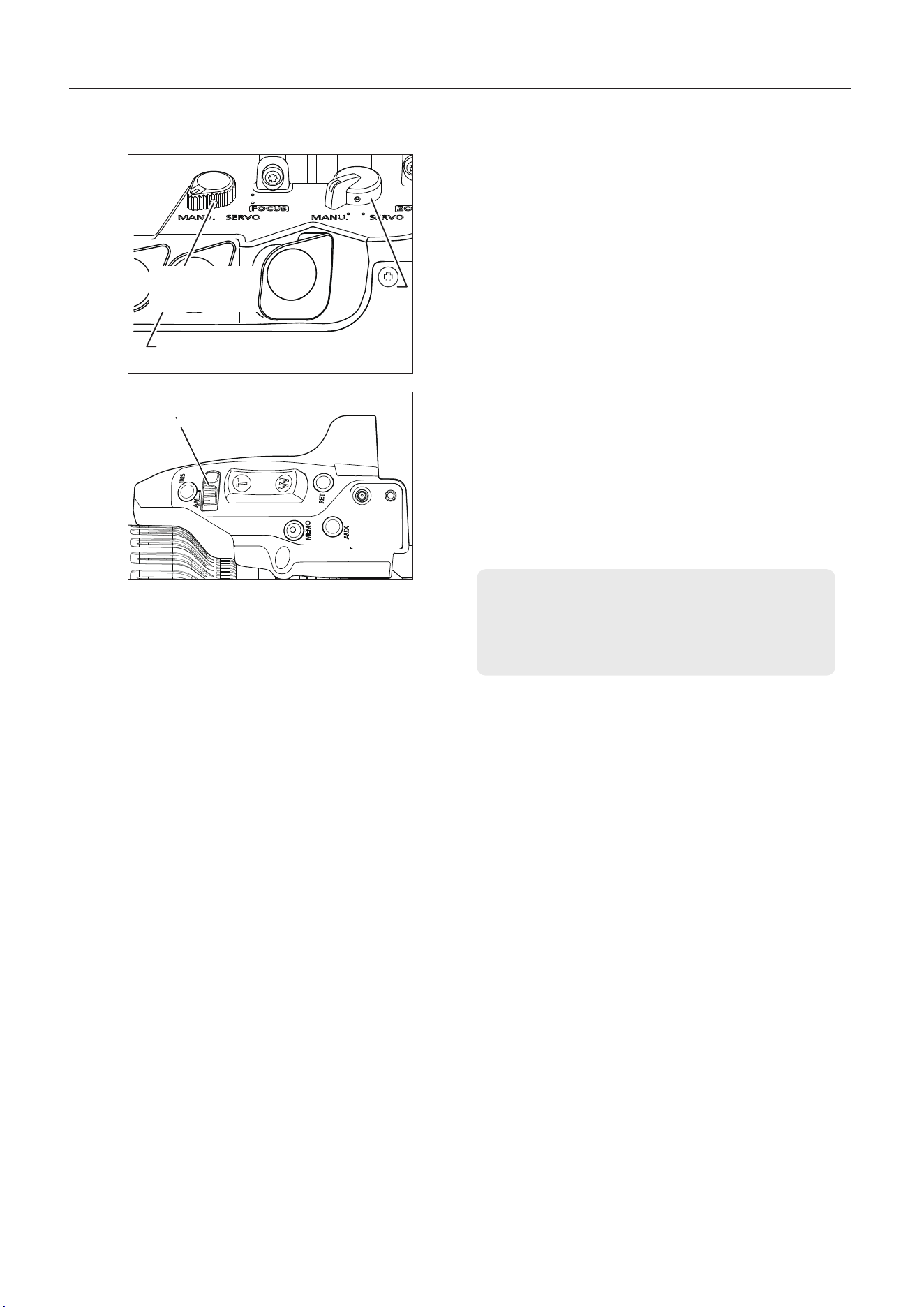
Iris A/M switch
Focus operation
change-over knob
Zoom operation
change-over knob
6 Set the zoom operation change-over knob and focus op-
eration change-over knob to the MANU. position.
7 Set the iris A/M switch to manual.
8 Manually turn the focus, zoom, and iris rings to make
sure the gears are engaged.
9 Tighten the three xing screws to the specied torque.
* Tightening torque : 63 – 80N・cm(6.4 – 8.2 kg・cm)
10 Mount the lens on the camera, connect the power/iris
control cable, switch the power on.
11 From the display, perform auto mechanical end adjust-
ment.
* For details on how to adjust the mechanical end
automatically, refer to "7-3 Automatic adjustment of
the mechanical end" on the next page.
35
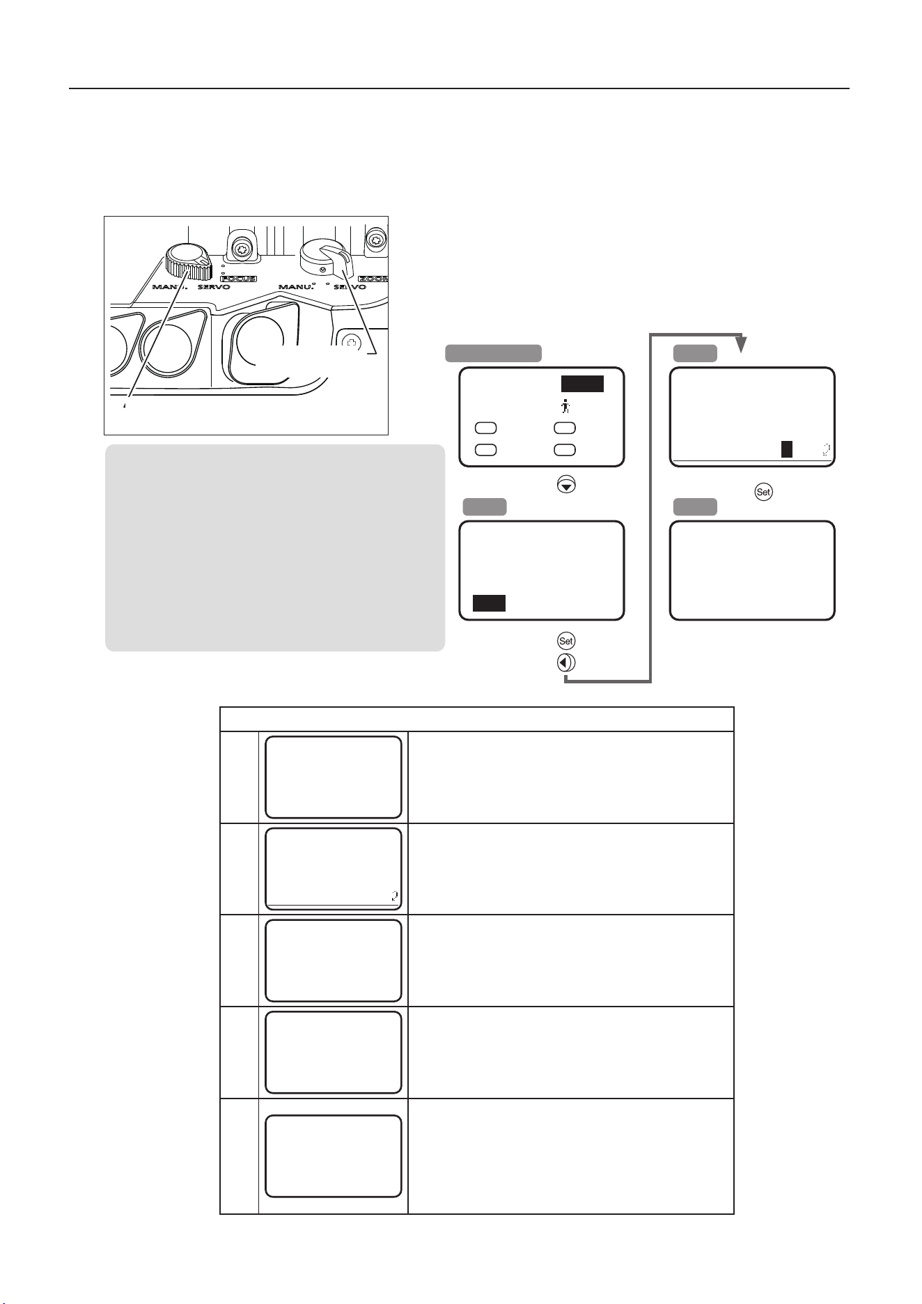
7-3. Automatic adjustment of the mechanical end
Automatically adjust the mechanical end of the zoom, focus and iris of the lens body and drive unit.
Always perform auto mechanical end adjustment when reattaching a drive unit to a lens.
1 Set the zoom operation change-over knob and focus opera-
tion change-over knob to the SERVO position.
2 From the display, perform auto mechanical end adjustment
as follows.
7 How to attach and detach the drive unit
NOTE
*1: To cancel automatic adjustment on screen B, select
[n] and press the display control key straight in (Set).
Display returns to screen A.
*2: Display blinks as the mechanical end is adjusted.
During the blinking, do not touch the focus drive gear,
zoom drive gear, or other control rings.
*3: In case of messages other than those shown on
screen M1, see the following list of messages.
Screen B
*1
Lens
AutoAdjust
OK?
y / n
Screen M1
*3
*2
to start
adjustment
Auto-Adjustment:
Succeeded
Lens Interface:
Connected
Sub screen
Top
◀
<Sub>
▼
[IG] 50 [
] 1
A
Fr1P
V
VTR
AM
Norm
R
RET
Screen A
×
7
Top <Sub>
[I-Tq] H [Trk] OFF
[Copy] [Z.M.]
[Adj]
▲
▶
Focus operation change-over
knob
Zoom operation
change-over knob
Message list
Screen
M1
Auto-Adjustment:
Succeeded
Lens Interface:
Connected
Displayed after successful auto mechanical end adjustment.
Press the display control key straight in (Set) to return to
screen A.
Screen
M2
Please Check
Servo / Manu
OK?
Displayed when the zoom or focus operation change-over
knob or both knobs are in the MANU. position. Set both
knobs to the SERVO position and press the display control
key straight in (Set) to return to screen A.
Screen
M3
Auto-Adjustment:
Succeeded
Lens Interface:
Non-Connected
Displayed after auto mechanical end adjustment when
communication between the drive unit and lens has not been
established.
Press the display control key straight in (Set) to return to
screen A.
Screen
M4
Auto-Adjustment:
Error
Lens Interface:
Non-Connected
Displayed if auto mechanical end adjustment fails. If the
message on screen M4 appears, please contact your Canon
sales representative or dealer.
Press the display control key straight in (Set) to return to
screen A.
Screen
M5
Auto-Adjustment:
Error
Lens Interface:
Connected
Displayed after unsuccessful auto mechanical end
adjustment when communication between the drive unit and
lens has been established. If the message on screen M5
appears, please contact your Canon sales representative or
dealer.
Press the display control key straight in (Set) to return to
screen A.

36
NOTE
A variety of professional camera accessories compatible with the φ15 mm and φ19 mm rod system can be used
with this lens.
For the target accessories, please contact your Canon sales representative or dealer.
8 Specications
8 Specications
CN5x11 IAS T/R1 (RF mount)
CN5x11 IAS T/P1 (PL mount)
Extender
1.0
×
1.5
×
Focal Length
11-55 mm 16.5-82.5 mm
Zoom Ratio
5
×
Maximum Relative Aperture
(T-Number)
T2.95 (at 11-41 mm)
T3.95 (at 55 mm)
T4.4 (at 16.5-61.5 mm)
T5.9 (at 82.5 mm)
Iris Blades
11
Image Circle
φ
29.6 mm
φ
43.3 mm
Aspect Ratio 1.78:1 1.9:1 1.9:1 1.5:1 1.78:1 1.9:1
Dimensions (H × V) 24.6 × 13.8 mm 26.2 × 13.8
mm 38.1 × 20.1 mm 36 × 24 mm 24.6 × 13.8 mm 26.2 × 13.8 mm
Angle of View
(H × V)
Wide 96.4° × 64.2° 100.0° × 64.2° 98.2° × 62.7° 95.0° × 72.1° 73.4° × 45.4° 76.9° × 45.4°
Tele 25.2° × 14.3° 26.8° × 14.3° 26.0° × 13.9° 24.6° × 16.6° 17.0° × 9.6° 18.0° × 9.6°
Minimum Object Distance
(M.O.D.)
[ from the image sensor ]
0.6 m (2.0’)
Object Dimensions
at M.O.D.
(
H × V
)
Wide 69.7 × 39.1 cm 74.2 × 39.1 cm 72.0 × 38.0 cm 68.0 × 45.3 cm 46.5 × 26.1 cm 49.5 × 26.1 cm
Tele 13.3 × 7.5 cm 14.2 × 7.5 cm 13.8 × 7.3 cm 13.1 × 8.7 cm 8.9 × 5.0 cm 9.5 × 5.0 cm
Front Diameter
φ
114 mm
Filter Thread Size
φ
112 mm P1 (lens barrel)
φ
127 mm P0.75 (hood)
Zoom Speed for Full Range
Approx. 0.5 s max. (at room temp.)
Focus Speed for Full Range
Approx. 1.4 s (at room temp.)
Power Source
DC 12 V(DC 10 V to 17 V)
Current Consumption
Max. 1.5 A
Operating Environment
Conditions
Temperature : -20˚C to +45˚C
Humidity: 5%RH to 95%RH (no condensation)
Size (W × H × L)
Approx.
186.6
×
129.9
×
301.0 mm
(
RF
mount)
Approx.
186.6
×
129.9
×
269.0 mm
(
PL
mount)
Weight
Approx. 3.01 kg (
RF
mount)
Approx. 2.92 kg (
PL
mount)

37
NOTE
A variety of professional camera accessories compatible with the φ15 mm and φ19 mm rod system can be used
with this lens.
For the target accessories, please contact your Canon sales representative or dealer.
8 Specications
CN7x17 KAS T/R1 (RF mount)
CN7x17 KAS T/P1 (PL mount)
Focal Length 17
-
120 mm
Zoom Ratio 7×
Maximum Relative Aperture
(T-Number)
T2.95 (at 17
-
91 mm)
T3.9 (at 120 mm)
Iris Blades 11
Image Circle
φ
31.4 mm
Aspect Ratio 1.78 : 1 1.9 : 1
Dimensions (H × V) 24.6 × 13.8 mm 26.2 × 13.8 mm
Angle of View
(H × V)
Wide 71.8° × 44.2° 75.2° × 44.2°
Tele 11.7° × 6.6° 12.5° × 6.6°
Minimum Object Distance
(
M.O.D
)
[ from the image sensor ]
0.85 m (2.8’)
Object
Dimensions at
M.O.D
(H × V)
Wide 86.6 × 48.6 cm 92.2 × 48.6 cm
Tele 12.0 × 6.7 cm 12.8 × 6.7 cm
Front Diameter
φ
114 mm
Filter Thread Size
φ
112 mm
P1 (lens barrel)
φ
127 mm
P0.75 (hood)
Zoom Speed for Full Range Approx. 0.5 s max. (at room temp.)
Focus Speed for Full Range Approx. 1.4 s (at room temp.)
Power Source DC 12 V (DC 10 V to 17 V)
Current Consumption Max. 1.5 A
Operating Environment
Conditions
Temperature : -20˚C to +45˚C
Humidity: 5%RH to 95%RH (no condensation)
Size (W × H × L)
Approx. 174.1 × 125.0 × 286.9 mm (RF mount)
Approx. 174.1 × 125.0 × 254.9 mm (PL mount)
Weight
Approx. 3.11 kg (RF mount)
Approx. 3.04 kg (PL mount)

38
Reference Information
This lens is a zoom lens for shooting movies.
• RF Cinema lenses were developed primarily for movie production, and have a color balance typical for movies. When using
this lens together with EF/RF lenses which are basically used to shoot still images, adjust the color balance (redo the white
balance etc.) as necessary.
• In general, the depth of eld becomes shallow and the focusing range becomes extremely narrow near the widest aperture
and when shooting a subject at close range. In addition, this tendency increases for lenses with longer focal lengths. When
shooting images, carefully check the focusing condition using the zoom mode of the nder or other means, and shoot a
sucient number of test images before performing focus operations.

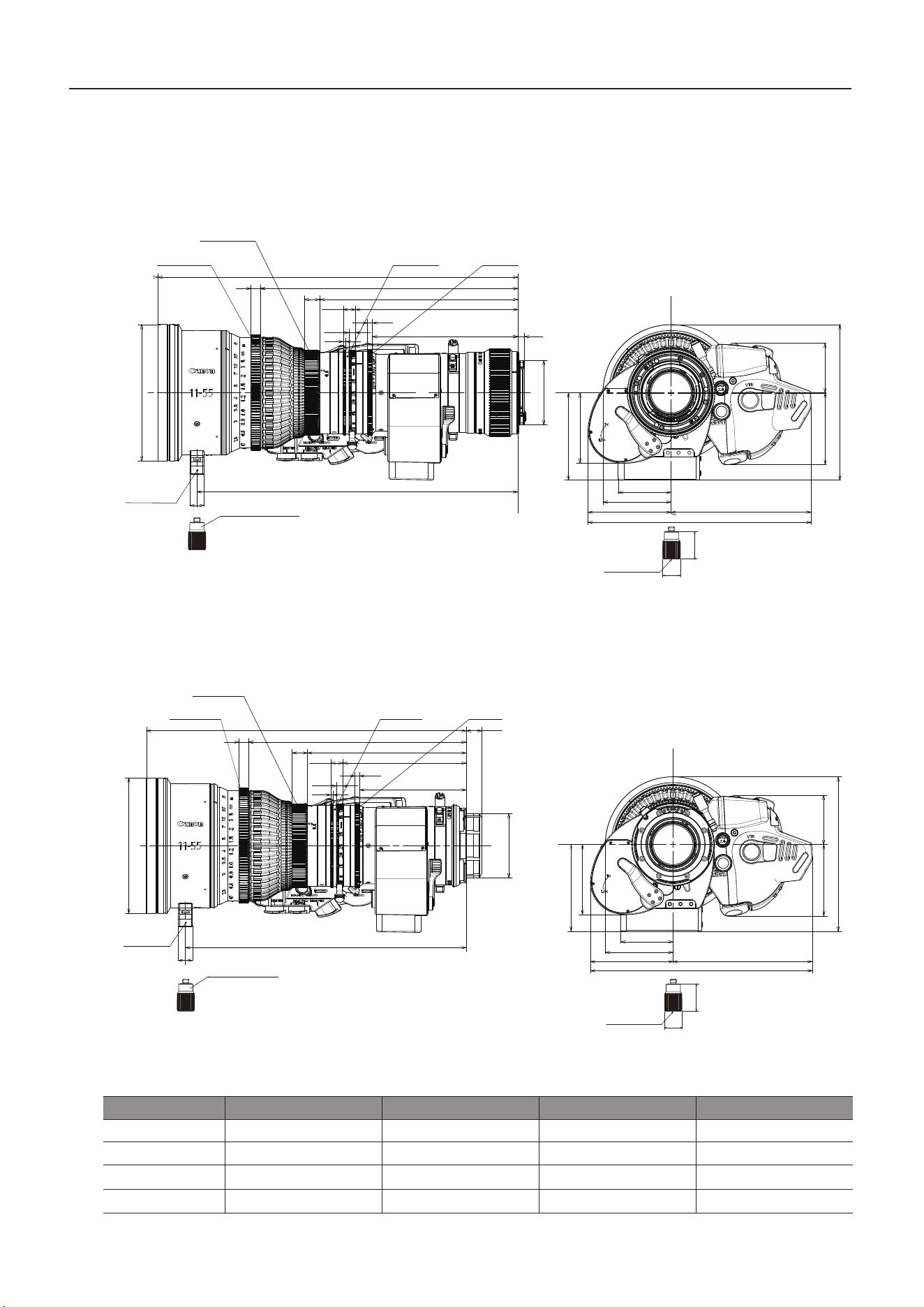
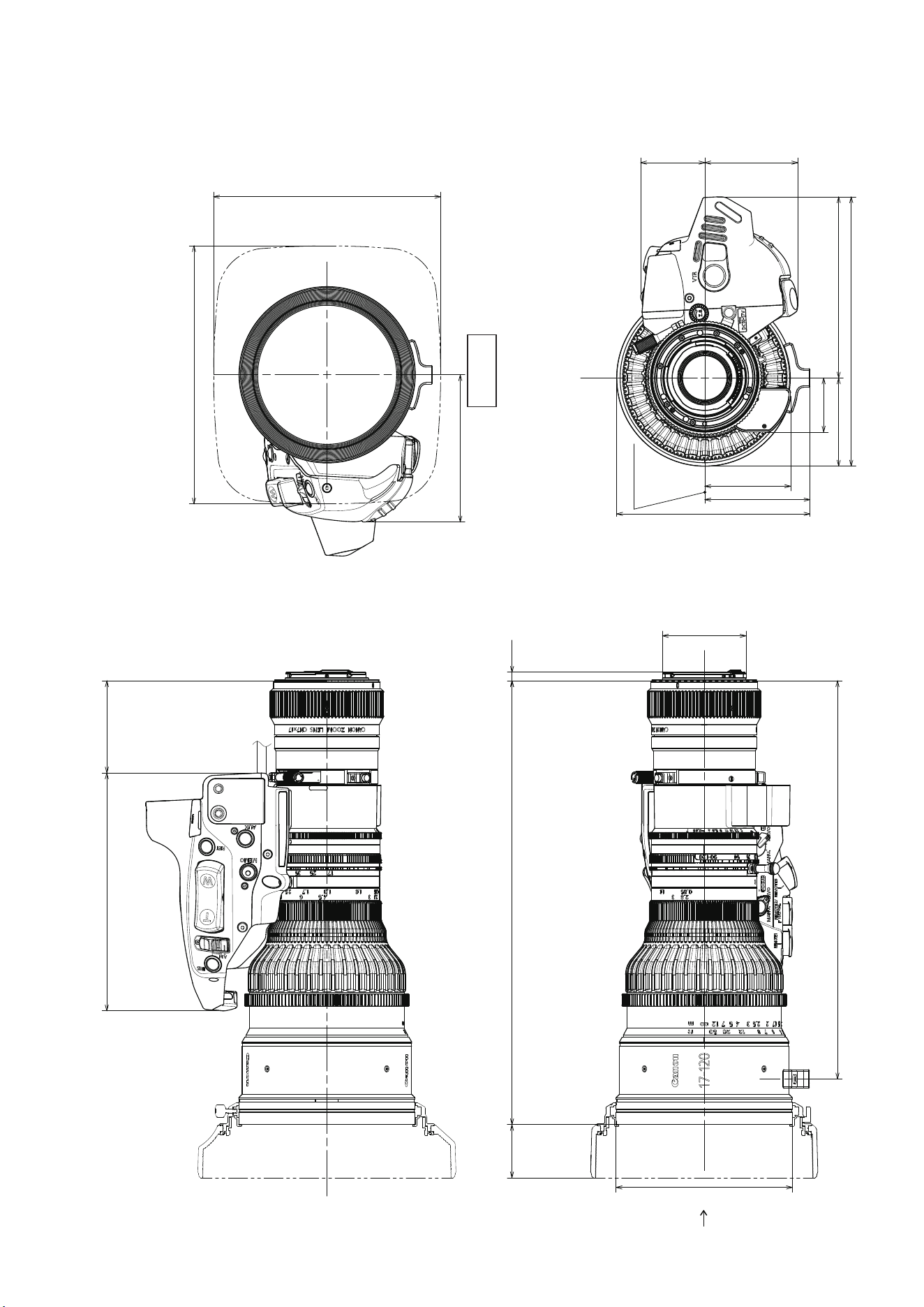
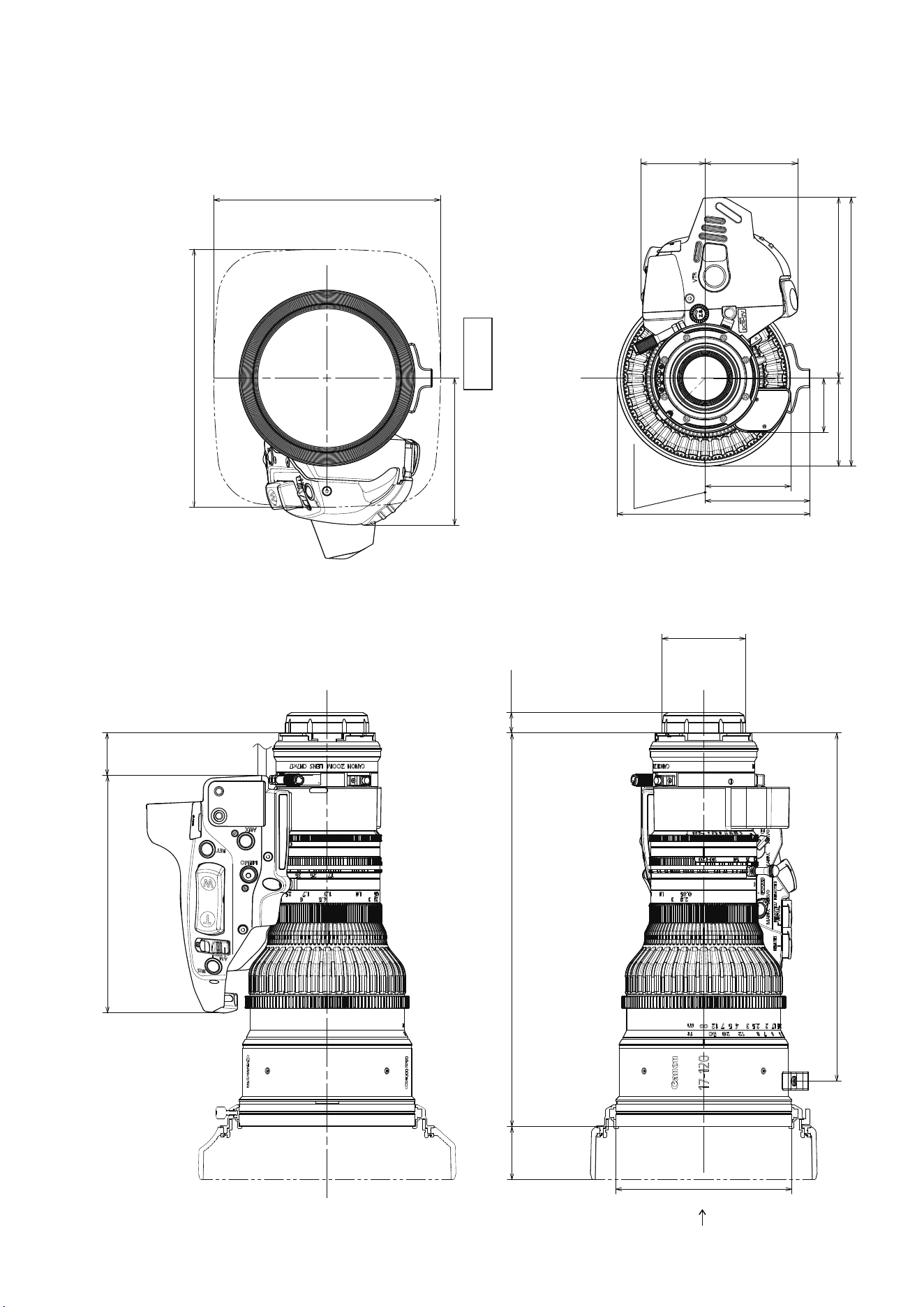
External views
A
(188.9)
(150.9)
95
72.9
58.9
60.1
41.5
129.9
44.2
56.9
69.5
117.1
186.6
45°
301
5.5
φ114
36.9
268.3
153.8
83.1
Index mark
φ54
(Unit : mm)
View A
(1) CN5x11 IAS T/R1
153.8
51.1
269
13.3
φ54
72.9
58.9
60.1
41.5
129.9
φ114
36.9
236.3
(188.9)
(150.9)
)
95
44.2
56.9
69.5
117.1
186.6
45°
Index mark
A
(Unit : mm)
View A
(2) CN5x11 IAS T/P1
(166.9)
5.5
286.9
257.4
φ114
68
125
55.5
35
57
174.1
117.1
60.1
41.5
φ
54
34.4
153.8
59.6
95
(146.9)
Index mark
A
(Unit : mm)
View A
(3) CN7x17 KAS T/R1
(Unit : mm)
68
125
55.5
35
57
174.1
117.1
60.1
41.5
13.3
254.9
225.4
φ114
φ54
34.4
153.8
27.6
(166.9)
95
(146.9)
Index mark
A
(4) CN7x17 KAS T/P1
View A

CANON INC.
30-2, Shimomaruko 3-chome, Ohta-ku, Tokyo, 146-8501, Japan
BT1-D047-C-ENG ©
CANON INC.
2025