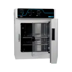
LRT50G2HC
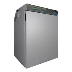
LRT21G1HC
7084 009-02
Use and
Care Manual
for Refrigerator
2
T
able
of
C
onTenTs
Contents Page
Please Read and Follow these Instructions ...................... 2
California Proposition 65 .................................................... 2
Disposal of Old Appliance .................................................. 3
Disposal of this Appliance .................................................. 3
Disposal of Batteries .......................................................... 3
Disposal of Carton .............................................................. 3
R290 Refrigerant ................................................................ 3
Important Safety Information .............................................. 4
Electrical Safety .................................................................. 4
Blocking for Safety .............................................................. 4
Safety Regulations ............................................................. 5
External Alarm Outputs ...................................................... 5
Setting Up ........................................................................... 5
Supplied Equipment ........................................................... 5
Installing the Equipment ..................................................... 6
Castors ................................................................................ 6
Dimensions ......................................................................... 7
Description of the Appliance .............................................. 7
Back-up Battery .................................................................. 8
Operating and Control Elements ........................................ 8
Switching the Appliance On and Off .................................. 9
Setting the Temperature ..................................................... 9
Door Open Alarm ................................................................ 9
Setting the Delay Time for the Door Open Alarm ............. 9
Audible Alarm Settings ..................................................... 10
Deactivating the Audible Alarm Function ......................... 10
Alarm Messages ............................................................... 10
Adjusting the Alarm Parameters .......................................11
Calling Up Stored Alarm Events and Reading the
Temperature Progression ..................................................11
Reset HAn ..........................................................................11
Resetting the Recorded Temperature Progression
.. 12
Alarm Test ......................................................................... 12
Calibrating the Control Sensor ......................................... 12
Product Sensor ................................................................. 12
Calibrating the Product Sensor ....................................... 13
Switching the Temperature Display Between Control
Sensor and Product Sensor ............................................. 13
Changing the Network Address ...................................... 13
Resetting the Parameters to Factory Settings................. 13
Setting the Real Time Clock ............................................ 14
Defrosting .......................................................................... 14
Setting the Display Indication for the Defrost Phase ....... 15
Temperature Display Mode ............................................. 15
Keypad Lock ..................................................................... 15
Interior Light ...................................................................... 16
Safety Lock ....................................................................... 16
Cleaning ............................................................................ 17
Cleaning the Dust Filter .................................................... 17
Troubleshooting ................................................................ 18
Customer Service ............................................................. 18
Turning Off the Appliance ................................................. 18
Warranty ............................................................................ 19
Changing over Door Hinges Model LRT21G1HC ............ 20
IMPORTANT
All types and models are subject to continuous
improvement. The manufacturer reserves the right
to make modifications to the shape, equipment
and technology.
Please Read and Follow these
Instructions
These instructions contain Danger, Warning and
Caution notes.
This information is important for safe and efficient
installation and operation.
Always read and comply with all Danger, Warning and
Caution notes!
DANGER!
Danger indicates a hazard which
will cause serious injury or death if
precautions are not followed.
WARNING!
Warning indicates a potentially hazardous
situation which, if not avoided, could
result in death or serious injury.
CAUTION!
Caution indicates a potentially hazardous
situation which, if not avoided, may result
in minor or moderate injury.
IMPORTANT
This indicates information that is especially
relevant to a problem-free installation and
operation.
California Proposition 65
- This product contains chemicals known to the state
of California to cause cancer or reproductive harm.
- This product can expose you to chemicals including
Diisononyl Phthalate (DINP) which is known to the
State of California to cause cancer. For more infor-
mation go to www.P65Warnings.ca.gov.
- This product can expose you to chemicals includ-
ing Di-isodecyl Phthalate (DIDP) which is known to
the State of California to cause birth defects or other
reproductive harm. For more information go to
www.P65Warnings.ca.gov.
3
s
afeTy
Disposal of Carton
The packaging is designed to protect the appliance and
individual components during transport and is made of
recyclable materials.
WARNING!
Keep packaging materials away from
children. Polythene sheets and bags can
cause suffocation!
If possible, please recycle packaging material at a recy-
cling facility.
Disposal of Old Appliance
DANGER!
Risk of child entrapment.
Child entrapment and suffocation are not problems of
the past.
Junked or abandoned refrigerators are still dangerous –
even if they will sit for “just a few days.”
If you are getting rid of your old refrigerator, please
follow these instructions to help prevent accidents.
Before you discard old appliances:
• Take off the doors.
• Leave the shelves in place so that children
may not easily climb inside.
• Cut off the power cable from the discarded
appliance. Discard separately from the
appliance.
• Be sure to follow your local requirements for
disposal of appliances.
Contact the trash collection agency in
your area for additional information.
Disposal of this Appliance
This appliance contains flammable gases within
the refrigeration circuit and insulation foam.
Contact the municipality or disposal company
in your area for information on approved
recycling or disposal.
Disposal of Batteries
A rechargeable battery is installed in the appliance.
The battery must be removed when you wish to
dispose of the appliance and sent for separate
waste treatment for batteries.
Contact a disposal company in your area for
information on approved disposal of batteries.
Do not damage or short-circuit the battery.
R290 Refrigerant
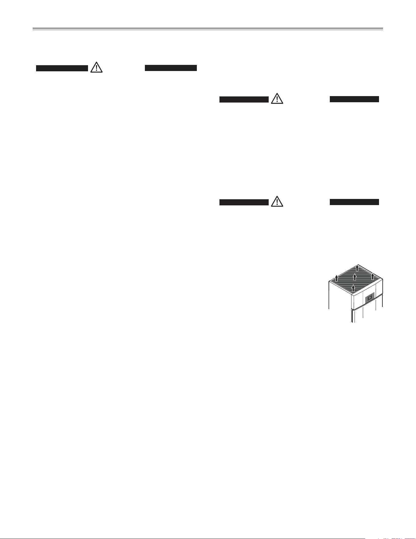
WARNING!
The refrigerant R290 contained within the
appliance is environmentally friendly, but
flammable. Leaking refrigerant can ignite.
To prevent possible ignition, follow the warnings
below:
•
Keep ventilation openings,
in the appliance enclosure
or in the built-in structure,
clear of obstruction.
• To ensure proper ventilation, the clearance
between the appliance top and the ceiling
must be at least 12 inches.
• Do not use mechanical devices or other
means to accelerate the defrosting process,
other than those recommended by the
manufacturer.
• Do not damage the refrigerant circuit.
• Component parts and power cords shall be
replaced with like components performed by
factory authorized service personnel only.
• Do not use electrical appliances inside the
food storage compartments of the appliance,
unless they are of the type recommended by
the manufacturer.
4
s
afeTy
Important Safety Information
• If the appliance is damaged on delivery,
contact the supplier immediately before con-
necting it to the power source.
• To guarantee safe operation, ensure that
the appliance is set up and connected as
described in this manual.
• Disconnect the appliance from the power
source if a fault occurs. Pull out the plug,
turn off or disable the power source.
• When disconnecting the appliance, always
pull it out by the plug; never pull on the
cable.
• Any repairs and work on the appliance
should only be performed by the customer
service department. Unauthorized work may
be dangerous to the user. The power source
cable should only be changed or replaced
by the customer service department.
• Do not store explosives or sprays using
combustible propellants such as butane,
propane, pentane, etc. in the appliance.
Electrical components might cause leaking
gas to ignite. You can identify such sprays by
the printed contents or a flame symbol.
• To prevent possible injury due to an electri-
cal shock, be sure to disconnect the power
cord or turn off the circuit breaker before
cleaning the appliance.
• To avoid injury or damage to the appliance,
do not use steam cleaning equipment to
clean the appliance.
• Do not operate the appliance in the pres-
ence of explosive fumes.
• In the event of a power outage, open the
door as infrequently as possible.
• To protect the appliance from possible dam-
age, allow it to stand 1/2 to 1 hour in place
before turning on the electricity. This allows
the refrigerant and system lubrication to
reach equilibrium.
Electrical Safety
Connect this appliance to a 15 amp or 20 amp, 110-
120 VAC, circuit which is grounded and protected by a
circuit breaker or fuse.
We recommend using a dedicated circuit for this appli-
ance to prevent circuit overload and the chance of
interruption to the appliance.
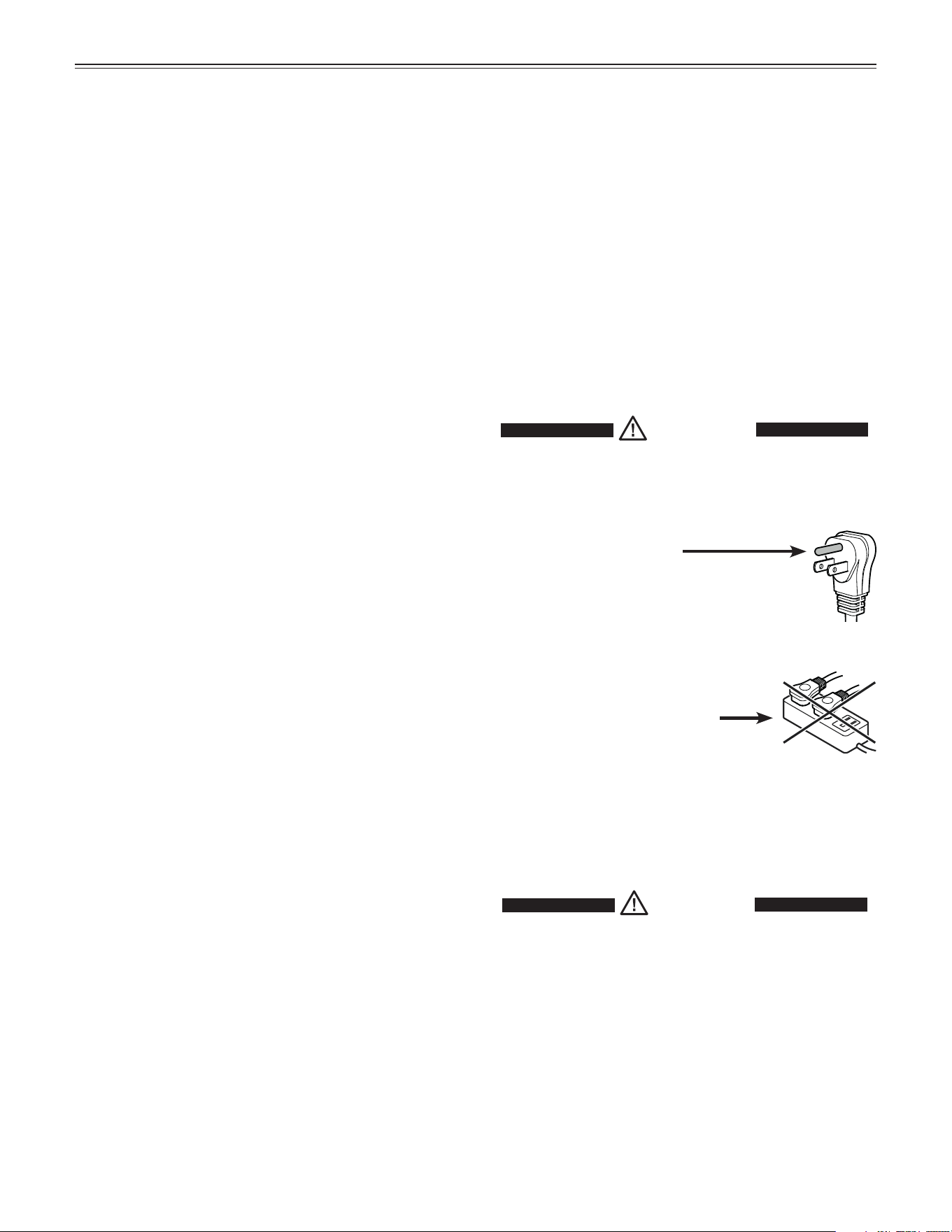
This appliance is equipped with a three-prong (ground-
ing) polarized plug for your protection against possible
shock hazards.
Where a two-prong wall receptacle is encountered,
contact a qualified electrician and have it replaced with
a properly grounded three-prong receptacle in accor-
dance with all local codes and ordinances.
WARNING!
Electrocution hazard.
Electrical grounding required.
•
Do not remove the round grounding
prong from the plug.
•
Do not use extension cords or
ungrounded (two-prong) adapters.
• Do not use a power cord that is frayed or
damaged.
•
Do not use a power strip.
Failure to follow these instructions may
result in fire, electrical shock or death.
Blocking for Safety
WARNING!
To avoid a hazard due to instability of the
appliance, it must be fixed in accordance
with the instructions.
5
s
eTTing
U
p
LRT21G1HC
LRT50G2HC
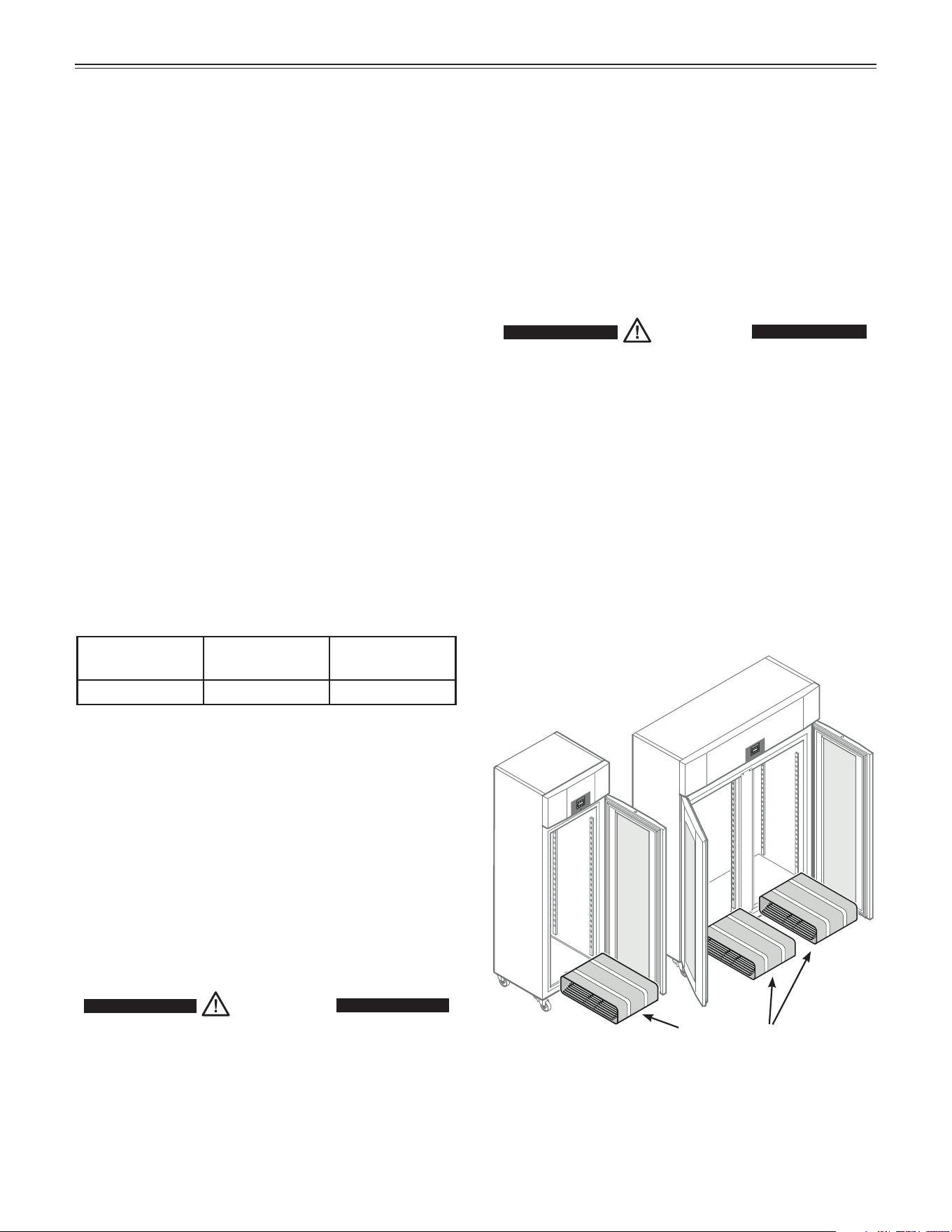
Grid shelves and shelf rails
Setting Up
CAUTION!
To avoid risk of personal injury or property
damage, have two people to move this
appliance into place.
Avoid placing the appliance in direct sunlight or near
the stove, range top, radiators and similar heat sources.
• Examine the unit and packaging for shipping dam-
age. Contact the carrier immediately if you suspect
there is any damage.
Supplied Equipment
External Alarm Outputs
The electronic control system is equipped with a floating
alarm output and an RS485 interface.
For information about connecting the appliance to
an external alarm or temperature monitoring system,
please contact your dealer.
Safety Regulations
The appliance is designed to cool and store laboratory
preparations at temperatures of between 28°F and 60°F
(-2.2°C and +15.5°C).
The appliance is not suitable for use in explosion-haz-
ard areas.
If valuable or temperature-sensitive substances or
products are stored, a separate, continuously monitor-
ing alarm system must be used. This alarm system
must be designed so that each alarm status is detected
immediately by an authorized person who can then
take appropriate action.
IMPORTANT
The appliance is not intended for outdoor use.
The appliance is not intended for storage of blood or
blood products.
Climate rating
The climate rating indicates at what room temperature
the appliance may be operated to achieve full cooling
capacity and what the maximum humidity level in the
area around the appliance may be to ensure that no
condensation forms on the exterior housing.
Climate Rating Max. Ambient
Temperature
Max. relative
humidity
5 104°F (40°C) 40%
The minimum room temperature at the place of installa-
tion is 50°F (10°C).
IMPORTANT
Do not operate the appliance outside the specified
ambient temperature range.
- The refrigerant circuit has been tested for leaks.
- The appliance complies with current safety regula-
tions C22.2 No. 120-13, UL 471 - 10
th
Edition
We recommend cleaning the appliance before turning it
on for the first time. See Cleaning.
WARNING!
Do not allow children to play with the
appliance. Children must not climb, sit or
stand on the shelves or door.
Failure to follow these instructions may
result in death or serious injury.
6
f
eaTUres
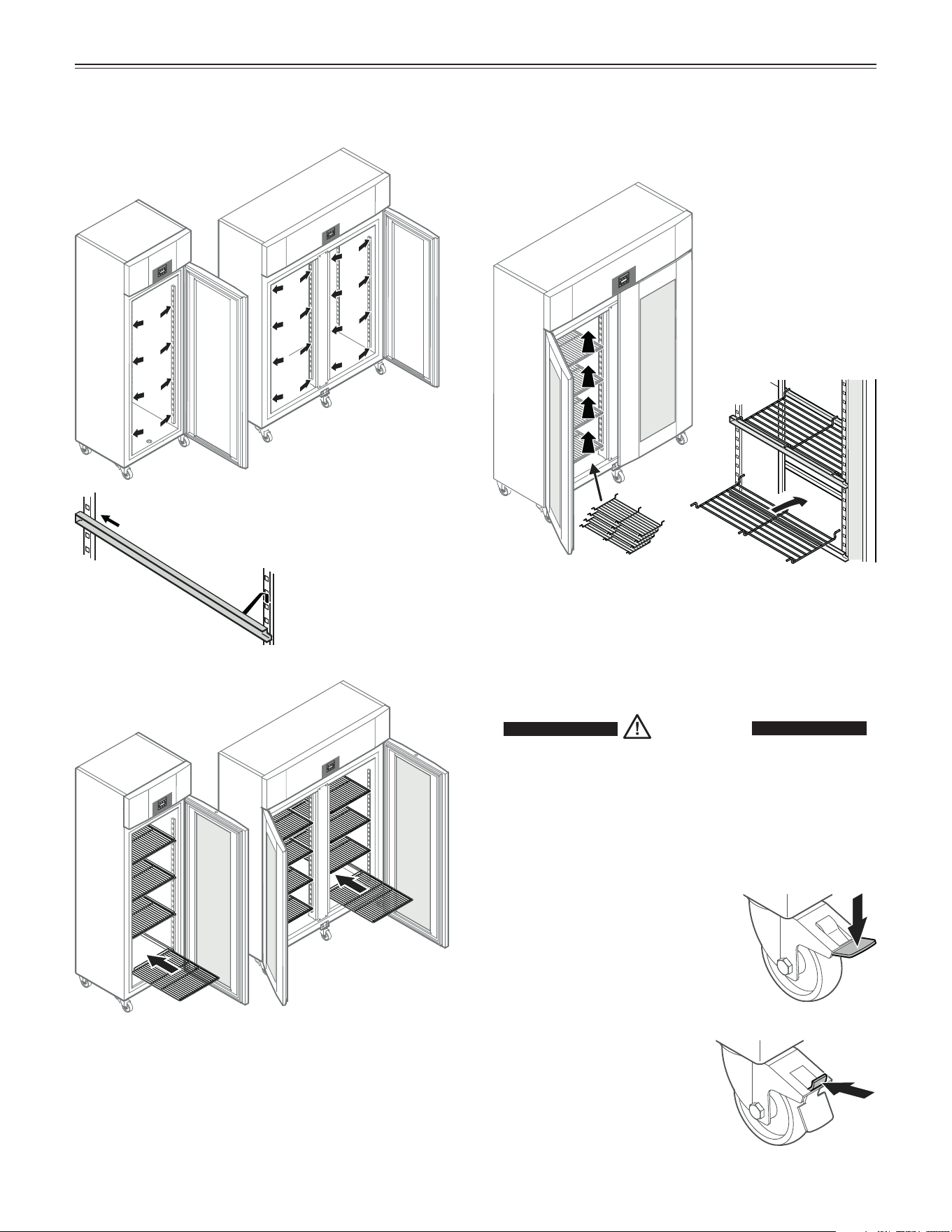
Installing the Equipment
Intermediate shelves LRT50G2HC
Insert the grid
shelves.
Suspend the rails at the desired height by
inserting into the rear clip-in strip first and
then clipping in at the front.
Place the supplied
intermediate shelves
onto the shelf rails.
IMPORTANT
The maximum load
per intermediate shelf
is 44 lbs (20 kg).
Unlocking the castor
Push back the lever at the top
with the tip of your shoe until it
snaps back to the initial posi-
tion.
Castors
To easily move the appliance on the floor, it is equipped
with castors. The left and right front castors are lockable
to keep the appliance in position.
Locking the castor
Press down the lever at the front
with the tip of your shoe until it
snaps into place.
CAUTION!
Risk of injury due to high spring tension.
Do not try to operate the locking lever with
your hands.
Always operate with protective footwear.
7
f
eaTUres
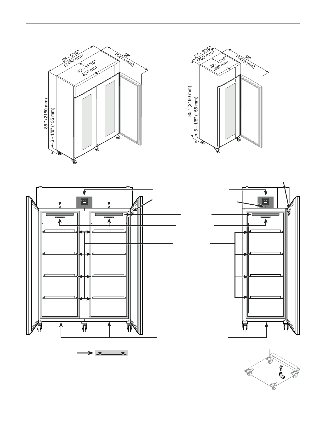
Description of the Appliance
IMPORTANT
The maximum load per grid
shelf is 132 lbs (60 kg).
Dimensions
LRT50G2HC
LRT21G1HC
Model plate
Lock
Lock
Lock
Model plate
Interior light
Adjustable grid
shelves
Operating and control elements
Stacking mark*
* Stacking mark
Only load the top shelf up to the stacking
mark. This is important to ensure that the
air can circulate properly and the tempera-
ture is even throughout the interior.
A drain hose with an R 3/4 con-
nection can be fitted to the under-
side of the appliance. The water
which collects in the interior during
cleaning can be drained off in this
way. An angled connector is sup-
plied with the appliance.
Cleaning water drain opening
8
o
peraTion
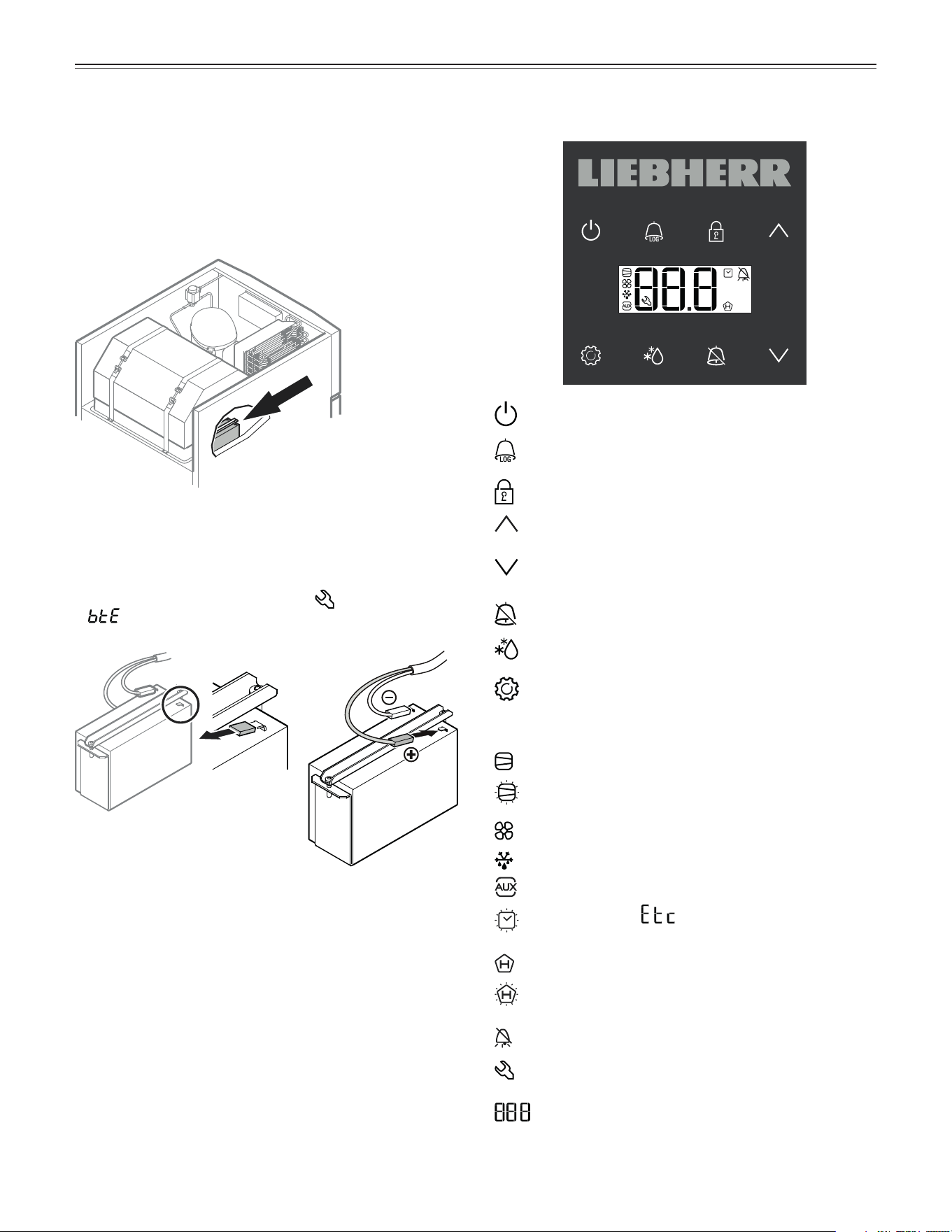
Operating and Control ElementsBack-up Battery
Before the appliance is turned on, the battery installed
in the compressor compartment must be connected.
This battery ensures that alarms are always reported,
even in the event of a power failure.
The battery is installed in the
compressor compartment at
the top of the appliance.
Attach the connector
to the positive pole on
the battery.
Remove cover.
IMPORTANT
The back-up battery should be connected before
the appliance is turned on. Otherwise, a fault
message will be displayed (LED flashes and
appears).
On/Off button (switching the appliance on and off)
AlarmLog button (for calling up stored alarm events
and reading the temperature progression)
Keypad lock
Up button (for navigating in the menu and
increasing values)
Down button (for navigating in the menu and
decreasing values)
Audible alarm Off button
Defrost button (for manually activating the defrost
function)
Enter button
Symbols in the display
Compressor is running
LED flashing. The compressor will start after the
pressure in the refrigerant circuit has equalized.
Fan in the interior is running
Appliance is defrosting
Product sensor is activated
LED flashing and appears in the display. The
real time clock must be reset.
HACCP function is activated
LED flashing. A power outage or interior temperatures
outside the permitted range have been recorded.
Alarm function
A fault has occurred in the appliance. Contact the
customer service department.
Digital display
9
o
peraTion
Setting the Temperature
• Press for 1 second. The temperature display
flashes.
• To increase the temperature (warmer): press
.
Note
Keep the button pressed down to change the tempera-
ture setting continuously.
• To reduce the temperature (colder): press
.
• Press
again.
The desired temperature setting is saved.
The temperature can be set at between -2.2°C and
+15.5°C (28°F and 60°F).
Door Open Alarm
If the door is left open for more than 1 minute, the audi-
ble alarm signal will sound and
and the tempera-
ture indication flash alternately in the display.
If the door must be opened for a lengthy period in
order to place items into the appliance, cancel the
audible alarm signal by pressing the
button.
The alarm switches back to standby when the door is
shut.
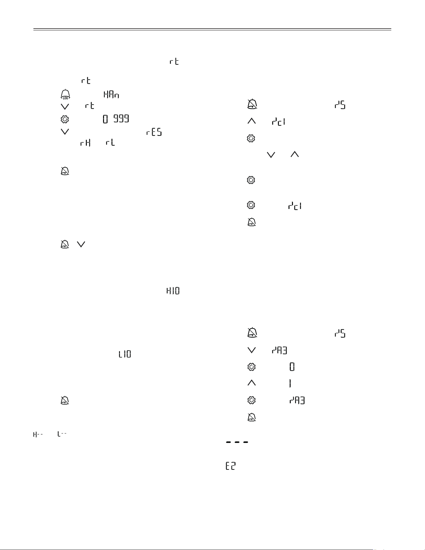
Setting the Delay Time for the
Door Open Alarm
The delay time until the audible alarm sounds after the
door has been opened can be adjusted.
• Press
for 5 seconds. Display = .
• Press
until appears in the display.
• Press
. Display = (minute).
Setting range = 1 - 5 minutes.
• Use buttons
and to select the desired setting.
• Press
. Display = .
• Press
for 5 seconds. The electronic control sys-
tem switches back to normal operation.
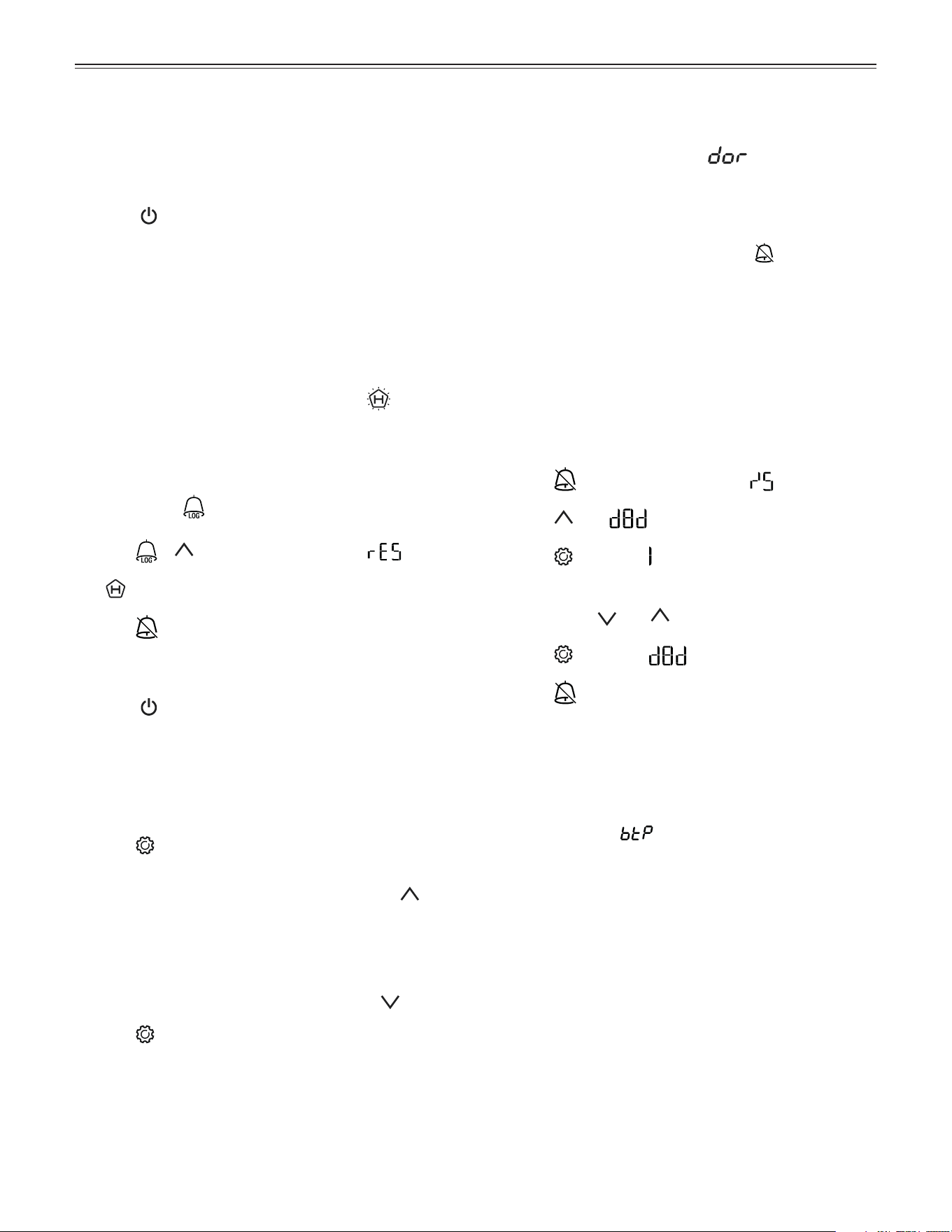
Switching the Appliance On and Off
Connect the appliance to the electrical outlet - the OFF
indicator and the temperature display flash alternately.
Switching the appliance on
Keep the
button pressed for approx. 3 seconds until
the temperature display lights up.
No alarm sounds or is displayed when the appliance is
switched on for the first time.
If the appliance is disconnected from the electrical out-
let for a long time after it has been switched on for the
first time and if the temperature inside the appliance
rises above the upper alarm limit, this will be detected
as a fault by the electronic control system (
appears
in the display).
When the appliance is switched on again, this display
must be reset as shown below.
• Press button
.
• Press
+ for 5 seconds. Display = .
The LED will now be lit permanently.
• Press
for 5 seconds. The electronic control sys-
tem switches back to normal operation.
Switching the appliance off
Keep the
button pressed for approx. 3 seconds - the
OFF indicator and the temperature display flash alter-
nately.
Power failure alarm
In the case of a power failure, the audible warning sig-
nal will sound and will be shown in the display.
10
o
peraTion
Deactivating the Audible Alarm
Function
The audible alarm function can be completely deacti-
vated if necessary.
Note
In this case, the sentence “The audible alarmsignal
will sound” in these operating instructions must be
skipped when reading the section in question.
• Press
for 5 seconds. Display = .
• Press
until appears in the display.
• Press . Display = .
• Use buttons
and to select the desired setting.
= audible alarm function activated
= audible alarm function deactivated.
• Press
. Display = .
• Press for 5 seconds. The electronic control sys-
tem switches back to normal operation.
Alarm Messages
1. LED flashes
If
appears in the display, the appliance has a fault.
Consult your nearest customer service point.
2. The temperature display flashes alternately with
or
The interior is too warm (HI) or too cold (LO). The audi-
ble alarm sounds (unless the audible alarm function has
been deactivated).
3. HA / HF / LED
flashes
There has been a power outage (HF) of some length or
the interior was too warm or too cold (HA) during a cer-
tain period of time.
Up to three alarm events can be stored and called up.
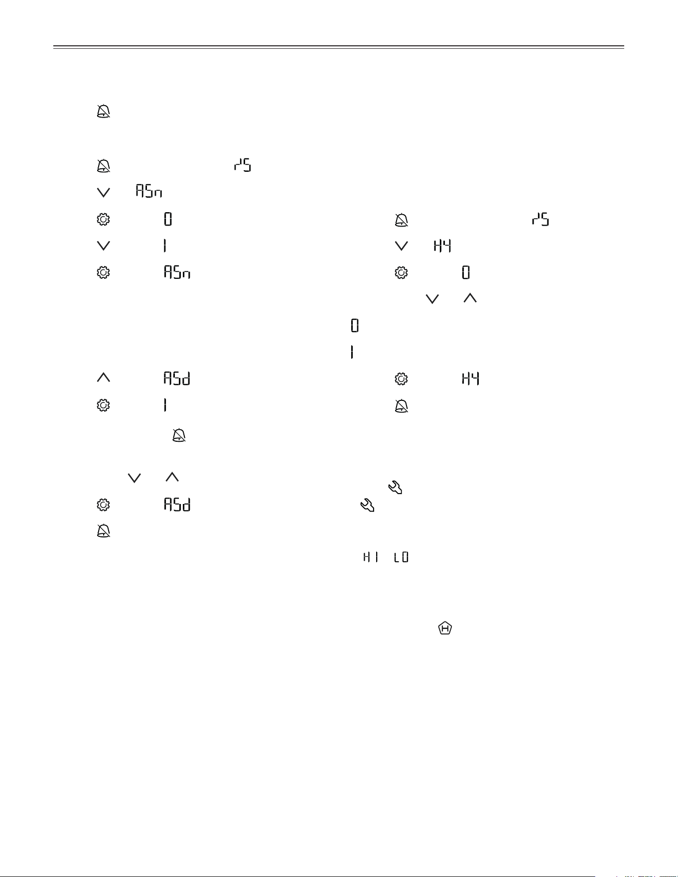
Audible Alarm Settings
The audible alarm will be muted for the current alarm
after the
button has been pressed. Complete the
following steps if you want the audible alarm function to
reactivate automatically.
• Press
for 5 seconds. Display = .
• Press
until appears in the display.
• Press
. Display = .
• Press
. Display = .
• Press . Display = .
Automatic reactivation of the audible alarm is now
active.
The delay time until the audible alarm sounds again
must be set.
• Press
. Display = .
• Press
. Display = .
Time in minutes after which the audible alarm will
sound again after the button has been pressed.
Setting range = 1 - 120 minutes.
• Use buttons and to select the desired setting.
• Press
. Display = .
• Press
for 5 seconds. The electronic control sys-
tem switches back to normal operation.
11
o
peraTion
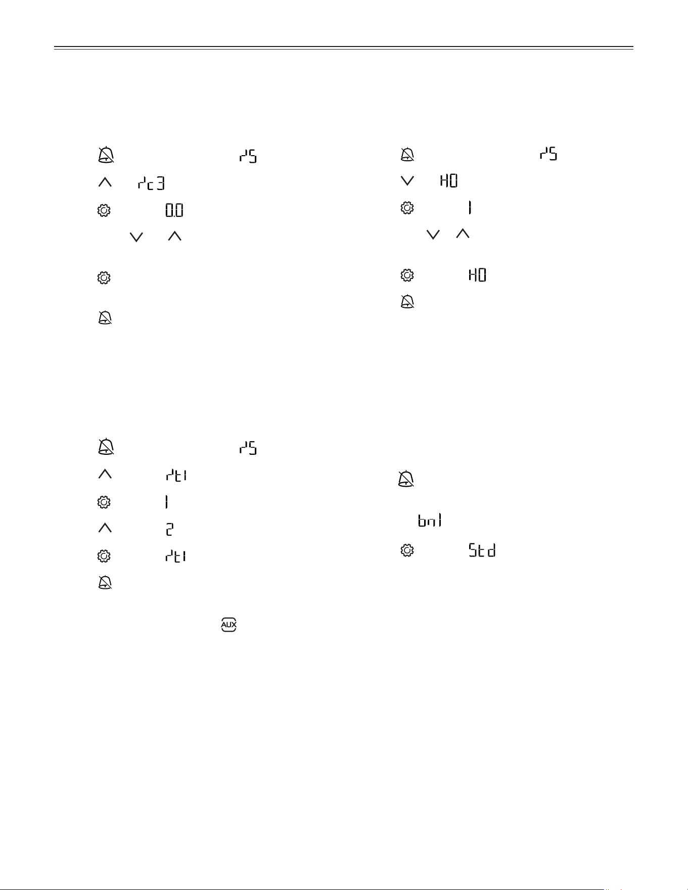
Adjusting the Alarm Parameters
The alarm limits (difference to the set temperature)
and the alarm delay (delay until alarm sounds) can be
adjusted.
Note
After a door has been opened or a defrosting process,
the alarm delay Ad will be extended by an additional
delay time (60 minutes). This additional delay time must
not be changed.
This means that a temperature alarm will appear later after
a door has been opened or a defrosting process than is
actually set using parameter Ad.
• Press
for 5 seconds. Display = .
• Press until appears in the display.
(AL = lower alarm limit)
• Press
. Display = temperature difference in °F.
• Use buttons
and to select the desired setting.
IMPORTANT
Set positive values only.
• Press
. Display = .
• Press . Display = (upper alarm limit).
• Press
. Display = temperature difference in °F.
• Use buttons and to select the desired setting.
IMPORTANT
Set positive values only.
• Press
. Display = .
• Press
. Display = .
• Press . Display = alarm delay in minutes.
• Use buttons
and to select the desired setting.
• Press . Display = .
• Press
for 5 seconds. The electronic control sys-
tem switches back to normal operation.
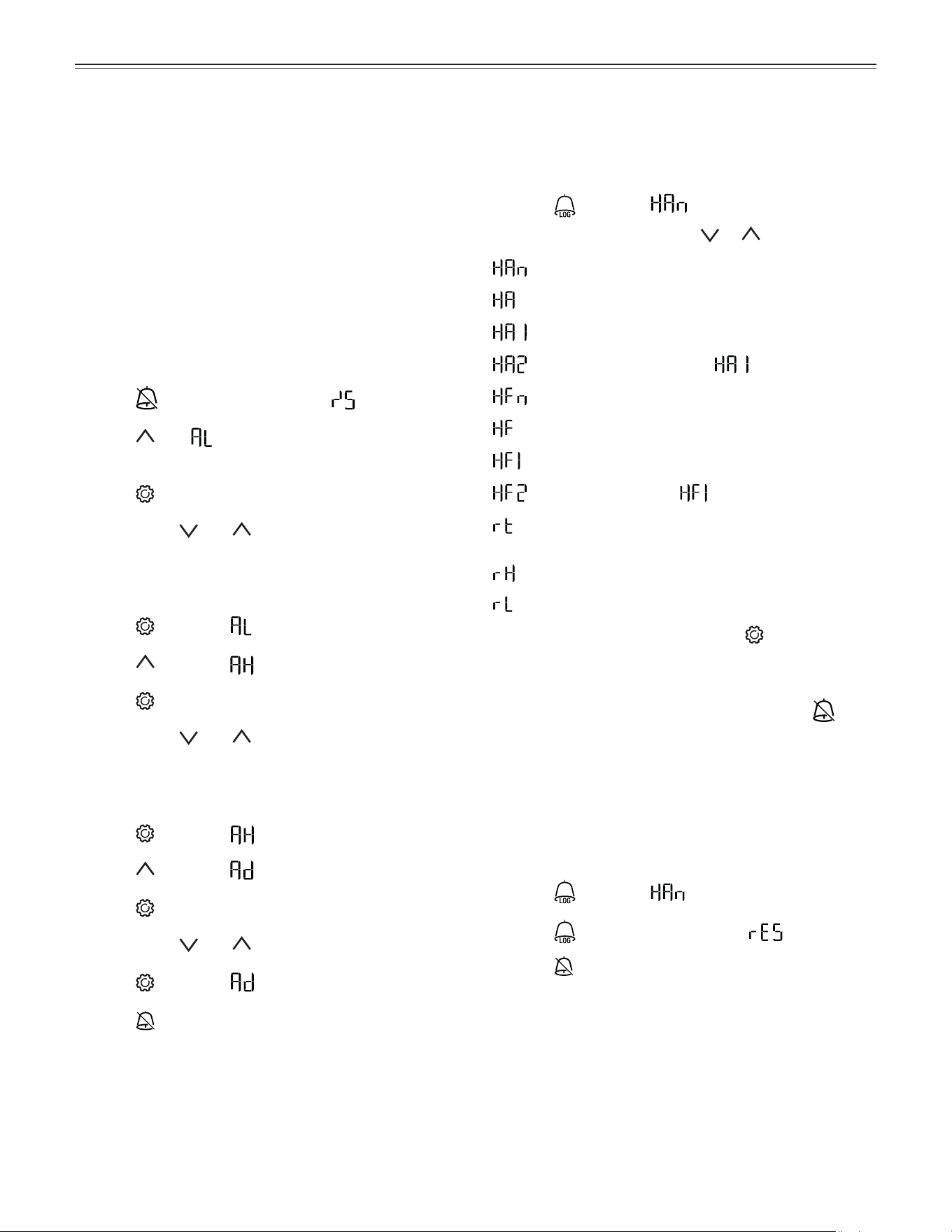
Calling Up Stored Alarm Events
and Reading the Temperature
Progression
• Press . Display = .
• Scroll through the list using
or .
Number of temperature alarms
Last temperature alarm
Last temperature alarm but one
Temperature alarm before
Number of power outages
Last power outage
Last power outage but one
Power outage before
Period in hours in which the maximum and mini-
mum interior temperatures were measured
Maximum (highest) measured temperature
Lowest measured temperature
• Select the required item using the
button. Press
this button again to return to the list.
Note
You can exit the menu at any time by pressing
for
5 seconds.
If no button is pressed within 60 seconds, the electronic
control system switches back automatically.
Reset HAn
• Press . Display = .
• Press
for 5 seconds. Display = .
• Press
for 5 seconds. The electronic control sys-
tem switches back to normal operation.
12
o
peraTion
Calibrating the Control Sensor
(standard sensor for temperature control)
Possible tolerances of the control sensor (the displayed
temperature compared to the actual interior tempera-
ture) can be offset with this function.
• Press
for 5 seconds. Display = .
• Press until appears in the display.
• Press . Display = correction value set at the factory.
•
Use buttons and to increase or decrease the
correction value in 0.1°F increments.
• Press . Display
= actual (corrected) interior tem-
perature.
• Press . Display
= .
• Press
for 5 seconds. The electronic control sys-
tem switches back to normal operation.
Product Sensor (optional accessory)
The temperature may be measured or recorded at any
point in the interior using the product sensor.
For information about ordering and connecting the prod-
uct sensor, contact your dealer.
Activating the sensor
• Press
for 5 seconds. Display = .
• Press until appears in the display.
• Press
. Display = .
• Press
. Display = .
• Press . Display = .
• Press
for 5 seconds. The electronic control sys-
tem switches back to normal operation.
If
appears in the display, the product sensor has
not been activated.
If
appears in the display, the product sensor has not
been connected, or is faulty.
Resetting the Recorded
Temperature Progression
Complete the following steps if you want to reset the
value saved for in the previous section to 0.
• Press . Display = .
• Press until appears in the display.
• Press . Display = - .
• Press for 5 seconds. Display = .
The values for
and (highest and lowest mea-
sured interior temperature) are then reset to the cur-
rent interior temperature.
• Press
for 5 seconds. The electronic control sys-
tem switches back to normal operation.
Alarm Test
This test checks the function of the internal and any
external connected alarm devices. The appliance’s refrig-
erating function remains switched on during this test.
• Press + for 5 seconds.
• The display changes to a temperature value of 0.2°F
below the set upper alarm limit.
• The temperature value now rises by 0.1°F every
2 seconds.
• When the upper alarm limit is reached,
appears in the display. An external alarm device
connected to the floating alarm output is now acti-
vated.
• The temperature value continues to rise up to
0.2°F above the upper alarm limit.
• The same process then takes place automatically
for the lower alarm limit. appears in the display.
The electronic control system automatically switches
back to normal operation.
Cancelling the test prematurely
• Press
for 5 seconds.
Note
If the values of the upper and lower alarm limit (AL and
AH in Adjusting the Alarm Parameters are set to 0,
and will appear in the display during this test.
Note
For a realistic temperature alarm test, an additional delay
time (60 minutes) applies as well as the adjustable alarm
parameters AL, AH and Ad.
After a door has been opened or a defrosting process,
the alarm delay Ad will be extended by an additional
delay time (60 minutes). This additional delay time must
not be changed.
This means that a temperature alarm will appear later
after a door has been opened or a defrosting process
than is actually set using parameter Ad.
13
o
peraTion
Resetting the Parameters to
Factory Settings
The alarm limits and sensor calibration values can be
reset to the factory settings using this function.
•
Disconnect the power cord.
•
Keep pressed down and connect the power
cord.
Display =
.
• Press . Display = .
The electronic control system automatically switches
back to normal operation.
Changing the Network Address
When connecting several appliances via the RS485
interface, each appliance must have its own network
address.
• Press
for 5 seconds. Display = .
• Press until appears in the display.
• Press
. Display = .
•
Use button or to change the network address
(1 - 207).
• Press
. Display = .
• Press
for 5 seconds. The electronic control sys-
tem switches back to normal operation.
Switching the Temperature
Display Between Control Sensor
and Product Sensor
• Press for 5 seconds. Display = .
• Press . Display = .
• Press .
Display = (control sensor).
• Press
. Display = (product sensor).
• Press .
Display = .
• Press
for 5 seconds. The electronic control sys-
tem switches back to normal operation.
If the product sensor is activated, appears in the
display.
Calibrating the Product Sensor
Possible tolerances of the product sensor (the set tem-
perature compared to the actual interior temperature)
can be offset with this function.
• Press
for 5 seconds. Display = .
• Press
until appears in the display.
• Press .
Display = .
•
Use buttons and to increase or decrease the
correction value in 0.1°F increments.
• Press .
Display = actual (corrected) product sensor
temperature.
• Press
for 5 seconds. The electronic control sys-
tem switches back to normal operation.
14
o
peraTion
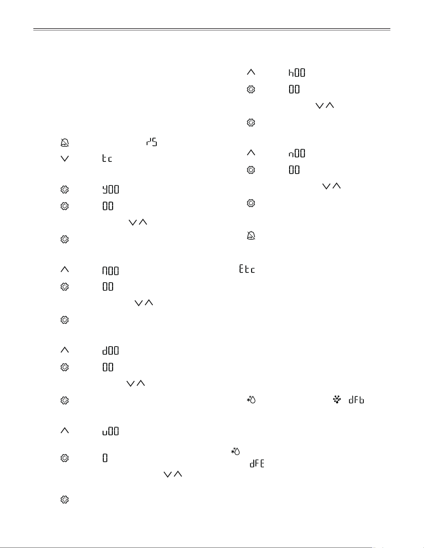
Setting the Real Time Clock
The real time clock is preset (CET). Other time zones or
summer/winter time must be adjusted manually.
Note
The time and date values in this section are depicted
with 0. The actual numbers displayed when setting the
real time clock may vary.
Activating the clock setting
• Press
for 5 seconds. Display = .
• Press . Display = .
Setting the year
• Press
. Display = . Year 0 - 99
• Press
. Display = (single or double digit).
• Set the year by pressing the buttons.
• Press
= save new setting.
Setting the month
• Press
. Display = . Month 1 - 12
• Press
. Display = (single or double digit).
• Set the month by pressing the
buttons.
• Press = save new setting.
Setting the day
• Press
. Display = . Day 1 - 31
• Press . Display = (single or double digit).
• Set the day by pressing the
buttons.
• Press = save new setting.
Setting the day of the week
• Press
. Display = .
Day of the week: 1 = Monday, 7 = Sunday.
• Press
. Display = .
• Set the day of the week by pressing the but-
tons.
• Press
= save new setting.
Setting the hour
• Press
. Display = . Hour 0 - 23
• Press
. Display = (single or double digit).
• Set the hour by pressing the buttons.
• Press
= save new setting.
Setting the minute
• Press
. Display = . Minute 0 - 59
• Press . Display = (single or double digit).
• Set the minute by pressing the
buttons.
• Press = save new setting.
Exiting the clock setting
• Press
for 5 seconds. The electronic control sys-
tem switches back to normal operation.
Note
When
appears in the display, the real time clock
must be reset.
Defrosting
The appliance defrosts automatically. The defrost water
drains into a tray near the refrigeration unit and evapo-
rates automatically through the compressor heat.
Activating the Defrost Function manually
When the appliance door has been left open for a long
time, the evaporator may become frosted. The defrost
function can then be activated manually.
• Press
for 3 seconds. Display = + .
The electronic control system switches back to normal
operation after the evaporator is defrosted.
The defrost function can be stopped earlier by pressing
the
button again.
Display =
.

15
o
peraTion
Setting the Display Indication
for the Defrost Phase
• Press for 5 seconds. Display = .
• Press until appears in the display.
• Press
. Display = .
• Use buttons
and to select the desired setting.
= + alternating display of and the current
temperature in the interior of the appliance.
= + temperature before the start of the defrost
phase (factory setting).
= Symbol + .
• Press . Display = .
• Press
for 5 seconds. The electronic control sys-
tem switches back to normal operation.
Keypad Lock
The keypad lock ensures that no unintentional changes
are made to the electronic control system.
Setting a PIN code for the keypad lock function
• Press
for 5 seconds. Display = .
• Press
until appears in the display.
• Press . Display = .
• Use button
or to choose a PIN code between
1 and 999.
• Press at the desired code number.
• Press
for 5 seconds. The electronic control sys-
tem switches back to normal operation.
Activating the keypad lock
• Press
. Display = .
• Enter the PIN code using button
or .
• Press
. Display = .
All functions except
and are locked.
Note
If an incorrect PIN code is entered, the electronic con-
trol system switches back to normal operation without
activating the keypad lock.
Deactivating the keypad lock
• Press
. Display = .
• Enter the PIN code using button
or .
• Press
. Display = .
All functions are enabled.
Note
If an incorrect PIN code is entered, the keypad lock
remains active.
Temperature Display Mode
You can choose the unit of temperature for the display
in degrees Fahrenheit or degrees Celsius.
The factory setting is degrees Celsius.
• Press
for 5 seconds. Display = .
• Press . Display = .
• Use buttons
and to select the desired setting.
= °C
= °F
• Press
. Display = .
• Press
for 5 seconds. The electronic control sys-
tem switches back to normal operation.
16
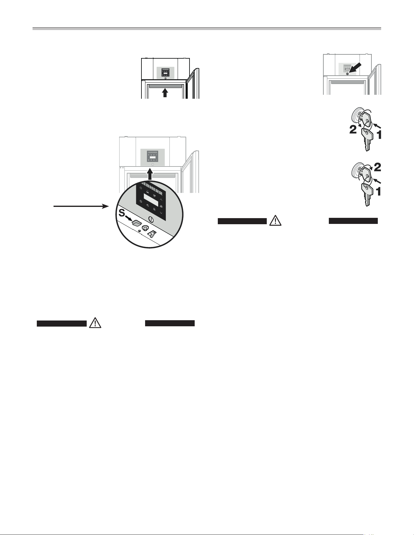
Interior Light
The interior of the appliance is lit
by an LED light strip at the top of
the interior container.
It can be switched on
and off by pressing the
switch on the underside
of the electronic control
panel.
o
peraTion
Safety Lock
The lock is equipped with a safety
mechanism.
Locking the appliance
• Insert the key and push as shown by
arrow 1.
• Turn the key 180° counterclockwise 2.
Unlocking the appliance
• Insert the key and push as shown by
arrow 1.
• Turn the key 180° clockwise 2.
WARNING!
Risk of child entrapment and suffocation
due to a locked appliance door.
Keep the key in a safe place out of reach
of children and not in the vicinity of the
appliance.
The light intensity of the LED light corresponds to
laser class 1/1M.
IMPORTANT
The light cover may only be removed by customer
service staff.
CAUTION!
Risk of eye damage.
If the cover is removed, do not look
directly at the light through optical lenses
from a close distance.
17
C
leaning
• Clean the inside of the appliance and equipment
parts with lukewarm water and a little detergent.
• Thoroughly dry all parts with a cloth.
• Do not damage or remove the model plate on the
inside of the appliance. It is very important for servic-
ing your appliance.
• Insert the shelf rails as shown in Installing the
Equipment.
• Insert the grid shelves.
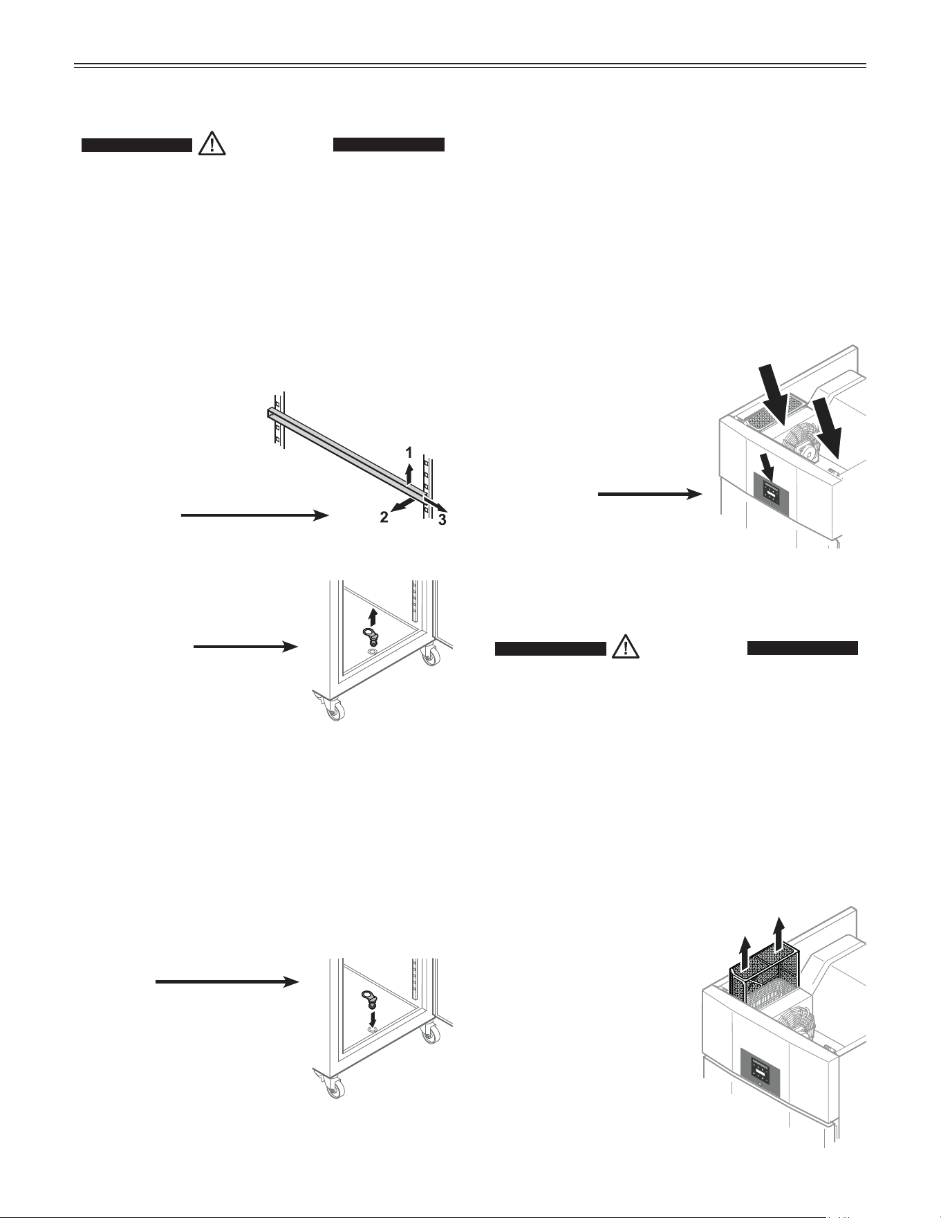
• Insert the plug into the drain
opening.
IMPORTANT
To avoid malfunctions due to
heavy frost on the evaporator,
the plug must be inserted.
Cleaning
WARNING!
• To prevent possible injury due to an
electrical shock, be sure to disconnect the
power cord or turn off the circuit breaker
before cleaning the appliance.
• To avoid injury or damage, do not use steam
cleaning equipment to clean the appliance.
Cleaning the appliance interior
• Remove the grid shelves.
• Remove the shelf rails.
Lift the rail at the front (1),
move inwards (2) and remove to
the front (3).
• Remove the plug from the
drain opening.
Cleaning the appliance outside
• Clean the door surface and outer walls with luke-
warm water and a little detergent or a good-quality
stainless steel cleaner.
IMPORTANT
Do not use abrasive or scouring pads or sponges.
Do not use concentrated cleaning agents. Never
use abrasive or acid-based cleaners or chemical
solvents. Otherwise, the stainless steel surface will
be permanently damaged.
• Ensure no cleaning water
penetrates into the electrical
components.
Cleaning the Dust Filter
WARNING!
Electrocution hazard.
Do not clean the dust filter when the
appliance is connected to the electrical
outlet.
Disconnect the power cord or turn off the
circuit breaker before cleaning the dust
filter.
IMPORTANT
Clean the dust filter at least twice per year.
• Remove the dust filter
by moving it upwards.
• Clean the filter with
water and detergent.
• Dry the dust filter and
reinstall it.
18
T
roUbleshooTing
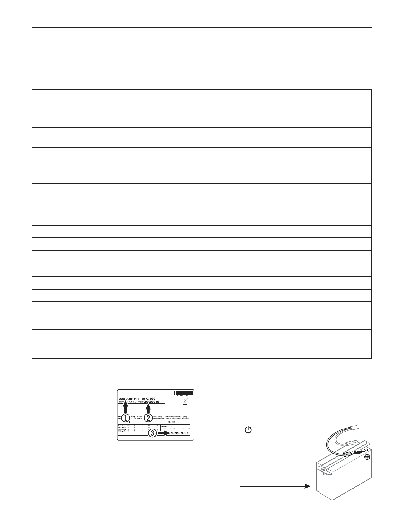
Customer Service
If none of the above pos-
sible causes apply, and
you can not rectify the
fault yourself, contact the
Liebherr Service Center.
Indicate the type (1) of
appliance, service num-
ber (2) and the appliance /
serial number (3) as shown on the model plate.
The position of the model plate is shown in the section
entitled Description of the Appliance.
Troubleshooting
Your appliance is designed and manufactured for a long life and reliable operation.
If a problem occurs during operation, check whether it is due to an operating error.
Please note that even during the warranty period, you may be responsible for certain repair costs.
Problem Possible cause and remedy
Appliance does not
work, display is off.
- Is the appliance turned on?
- Is the power cord properly inserted in the outlet?
- Is the circuit breaker or fuse in working order?
Motor seems to
run too long.
- Is the ambient temperature too hot? See Safety Regulations.
- Has the appliance been opened too often or left open too long?
The temperature is
not cold enough.
- Is the temperature setting correct? See Setting the Temperature.
- Does a separately installed thermometer show the correct reading?
- Is the ventilation system working properly?
- Is the appliance set up too close to a heat source?
Temperature alarm test
does not work as required.
- See „Adjusting the alarm parameters“ and „Alarm test“
Error codes displayed Cause and further action
E0 or E1 or E2 or rE Sensor error. > Contact the customer service department.
EE or EF Error in the electronic control system. > Contact the customer service department.
LO Temperature in the interior is too low. > Contact the customer service department.
HI Temperature in the interior is too high (warm). > First make sure that the door is closed
properly. If the HI display does not disappear after approx half an hour, contact the cus-
tomer service department.
dor The appliance door has been left open for more than 1 minute. > Close the door.
Etc Real time clock error. > Reset the real time clock.
btE Back-up battery error. > Check if the battery is connected properly. See Back-up
Battery. If the connection is correct and the error code is still displayed, contact the cus-
tomer service department.
HF or HA There has been a power outage (HF) of some length or the interior was too warm or too
cold (HA). > See Calling Up Stored Alarm Events and Reading the Temperature
Progression.
Turning Off the Appliance
If the appliance is to be left switched off for any
length of time, complete the following steps to discon-
nect the power failure alarm battery from the elec-
tronic control system.
• Keep the
button pressed for
approx. 3 seconds.
> The OFF indicator and the tem-
perature display flash alternately.
• Remove the connector of the
battery.

19
W
arranTy
COMMERCIAL LABORATORY AND MEDICAL PRODUCTS
FULL THREE YEAR WARRANTY
For three years from the date of original purchase, your Liebherr warranty covers all parts and labor to repair or
replace any part of the product which proves to be defective in materials or workmanship under normal and proper
use and maintenance as specified by Liebherr and upon proper installation and start-up in accordance with the
Owner’s Use and Care Guide supplied with each Liebherr unit.
TERMS APPLICABLE TO EACH WARRANTY
This warranty will apply to products purchased and located in the United States and Canada. Products must be
purchased in the country where service is requested. Any part covered under the above warranties that is determined
by Liebherr to have been defective within the time frame is limited to the repair or replacement, including labor
charges, of defective parts or assemblies. The labor warranty will include standard straight time labor charges
only and reasonable travel time, as determined by Liebherr. This warranty is void for any misuse of the intended
application of these products.
All service provided by Liebherr under the warranty must be performed by authorized Liebherr service representatives,
unless otherwise specified by Liebherr. The warranty does not cover any parts or labor to correct any defect or
damage caused by negligence, accident, fire, flood, acts of God, improper use, improper maintenance, improper
delivery, improper installation, power interruptions, power surges, incorrect electric current, voltage or supply, use
of extension cords, improper grounding, removal and reinstallation of the product if it is not installed in accordance
with published installation instructions or in an inaccessible location, service cost or service call to instruct the user
on the proper use of the product or repairs to parts or systems resulting from unauthorized modifications made to
the product repairs when the product is used in a manner that is contrary to published user or operator instructions
and/or installation instructions.
Liebherr is not responsible for economic loss, profit loss or direct, indirect or consequential damages, losses
or other costs and expenses resulting from any spoilage of any items stored in a Liebherr refrigeration system
including refrigerators, freezers, and wine coolers whether they be food, medicine, wine or otherwise. In no event
will Liebherr have any liability or responsibility whatsoever for damage to surrounding property, including but not
limited to cabinetry, floors, ceilings and other structures or objects around the product. You are solely responsible
for any structure and setting for the product including but not limited to all electrical, plumbing or other connecting
facilities, for proper foundation/flooring and for any alterations including without limitation cabinetry, walls, flooring
and shelving. Warranties are void if the original serial numbers have been removed, altered or cannot be readily
determined. Liebherr reserves the right to amend or alter this warranty and/or any warranty terms at Liebherr’s
discretion.
THE REMEDIES DESCRIBED ABOVE FOR EACH WARRANTY ARE THE ONLY ONES WHICH
LIEBHERR WILL PROVIDE, EITHER UNDER THESE WARRANTIES OR UNDER ANY WARRANTY
ARISING BY OPERATION OF LAW. LIEBHERR WILL NOT BE RESPONSIBLE FOR ANY
CONSEQUENTIAL OR INCIDENTAL DAMAGES ARISING FROM THE BREACH OF THESE
WARRANTIES OR ANY OTHER WARRANTIES, WHETHER EXPRESS, IMPLIED OR STATUTORY.
Some states/provinces do not allow the exclusion or limitation of incidental or consequential damages so the above
limitation or exclusion may not apply to you. This warranty gives you specific legal rights and you may also have other
legal rights which vary from state to state, or province to province.
For all other warranty inquiries or to receive parts and/or service and the name of the Liebherr authorized service
representative nearest you, for the USA and Canada, contact the Liebherr designated national service provider
at service-commercial.us@ liebherr.com or call 1-844-LICOSVC (1-844-542-6782) or contact your authorized
Liebherr dealer or distributor.
20
Changing over Door Hinges
Model LRT21G1HC
Door hinges should only be changed by a trained
expert.
Changing over the door hinges requires two people.
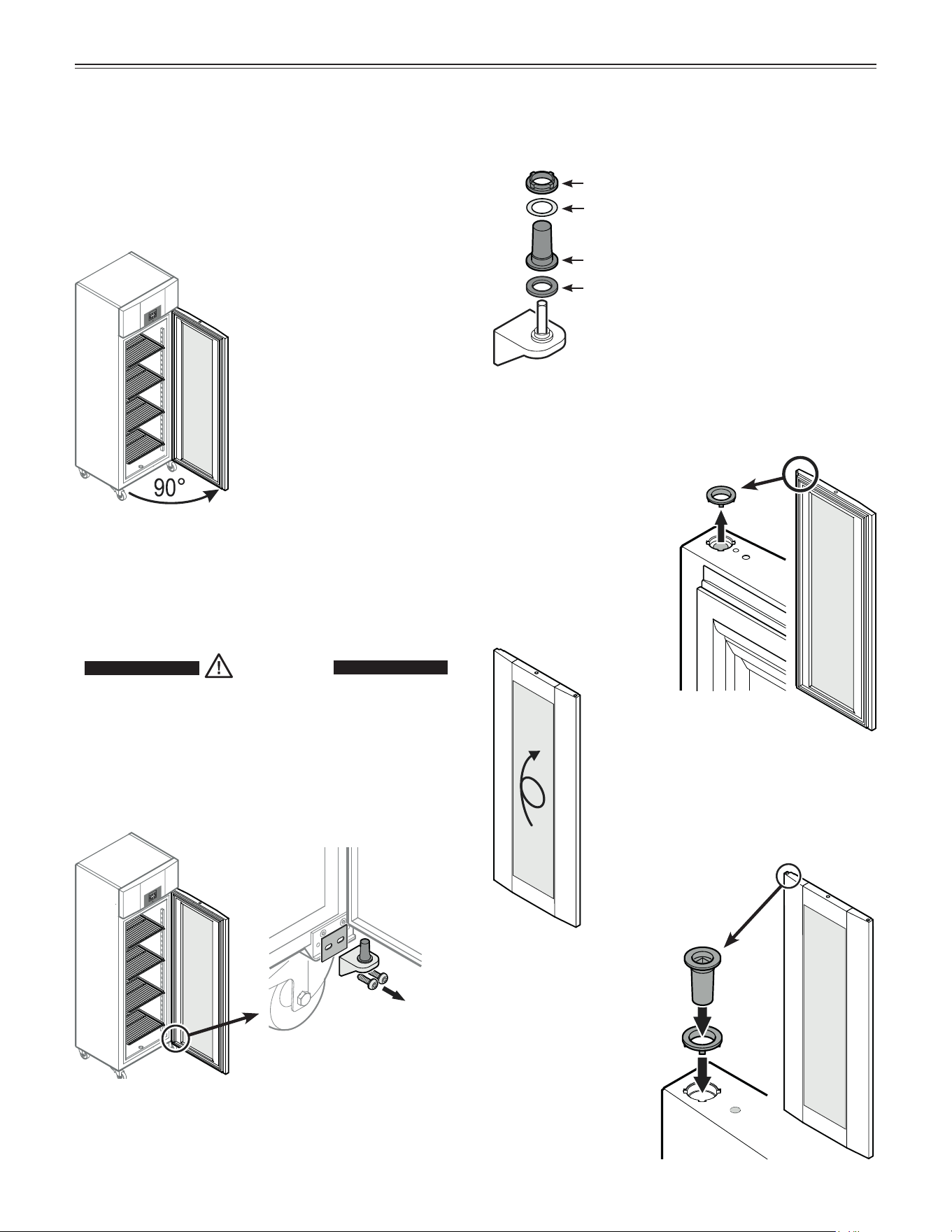
Changing over Door hinges
1. Open the door approx. 90°.
IMPORTANT
The door must be opened 90°
before the lower hinge bracket
is removed.
This will hold the self-closing
mechanism that is integrated
into the door in the required
position for installation.
IMPORTANT
If the door is removed and reinstalled in the closed
position, this will lead to destruction of the self-
closing mechanism on the first opening of the door.
2. Remove the hinge bracket and
spacer plate.
Remove the door downwards.
4. Remove bearing
ring from upper door
mounting.
3. Remove the hinge components
from the hinge bracket.
Bearing ring
Brass washer
Hinge bushing
Plastic washer
Note
The hinge bushing with brass washer and
bearing ring may stick in the door mount-
ing when you pull out the hinge bracket
and, in this case, must be removed from it.
5. Turn the door by 180°.
6. Insert the bearing ring
and hinge bushing
into the upper door
mounting.
CAUTION!
Risk of injury and damage due to a falling
appliance door.
The door must be held secure by one
person to ensure that a second person can
remove or install the hinge components.
21
Changing over Door hinges
Torx™
TX 25
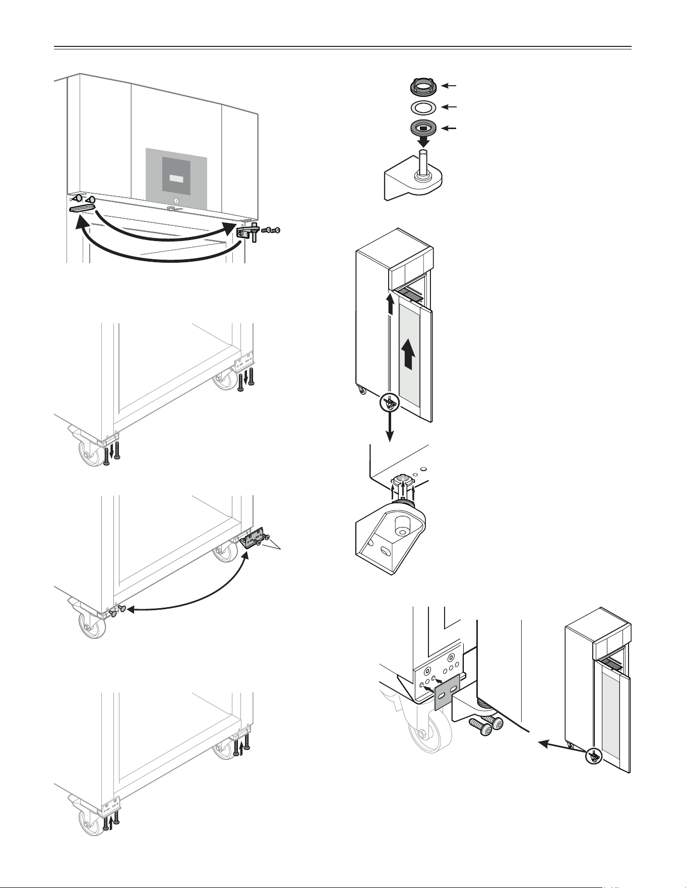
7. Transfer upper hinge bracket
and covers to the opposite side.
8. Remove the front screws of the
front castors using a 4 mm met-
ric Allen key.
9. Remove the base mounting
bracket and plugs and attach on
the other side.
10. Reinsert the screws, using a
4 mm metric Allen key.
Brass washer
Plastic washer
11. Fit the hinge components
on the hinge bracket.
12. Keeping the door open at 90°,
suspend in top square pin.
IMPORTANT
It is essential that the door is
open at an angle of 90° during
installation.
If the door is installed in the
closed position, this will lead to
destruction of the self-closing
mechanism on the first opening
and closing of the door.
13. Install the hinge bracket with the
fitted hinge components in the
lower door mounting.
Note
The tabs on the bearing ring must fit
into the recesses of the door mount-
ing during installation. If necessary,
rotare the upper ring.
14. Screw the hinge bracket with spacer plate
into place using a 4 mm metric Allen key.
IMPORTANT
Tighten the screws firmly.
Bearing ring


www.liebherr-appliances.com
For Service in the U.S. and Canada
Toll Free: 1-844-LICOSVC or 1-844-542-6782
Email: service-commercial.us@liebherr.com
*708400902*