Turret

Network Turret Camera·Quick Start Guide
1
About this Manual
The Manual includes instruc
ons for using and managing the
product. Pictures, charts, images and all other informa
on
hereina
er are for descrip on and explana on only. The
informa
on contained in the Manual is subject to change, without
no
ce, due to firmware updates or other reasons. Please find the
latest version in the company website
Please use this user man
ual under the guidance of professionals.
Legal Disclaimer
REGARDING TO THE PRODUCT WITH INTERNET ACCESS, THE USE OF
PRODUCT SHALL BE WHOLLY AT YOUR OWN RISKS. OUR COMPANY
SHALL NOT TAKE ANY RESPONSIBILITES FOR ABNORMAL OPERATION,
PRIVACY LEAKAGE OR OTHER DAMAGES RESULTING FROM CYBER
ATTACK,
HACKER ATTACK, VIRUS INSPECTION, OR OTHER INTERNET
SECURITY RISKS; HOWEVER, OUR COMPANY WILL PROVIDE TIMELY
TECHNICAL SUPPORT IF REQUIRED.
SURVEILLANCE LAWS VARY BY JURISDICTION. PLEASE CHECK ALL
RELEVANT LAWS IN YOUR JURISDICTION BEFORE USING THIS
PRODUCT IN ORDER TO ENSURE THAT YOUR USE CONFORMS THE
APPLICABLE LAW. OUR COMPANY SHALL NOT BE LIABLE IN THE
EVENT THAT THIS PRODUCT IS USED WITH ILLEGITIMATE PURP
OSES.
IN THE EVENT OF ANY CONFLICTS BETWEEN THIS MANUAL AND THE
APPLICABLE LAW, THE LATER PREVAILS.
Regulatory Information
FCC Information

Network Camera·Quick Start Guide
2
Please take a en on that changes or modifica on not expressly
approved by the party responsible for compliance could void the
user’s authority to operate the equipment.
FCC compliance: This equipment has been tested and found to
comply with the limits for a Class B digital device, pursuant to part
15 of the FCC Rules. These limits are designed to provide reasonable
protec
on against harmful interference in a residen al installa
on.
This equipment generates, uses and can radiate radio frequency
energy and, if not installed and used in accordance with the
instruc
ons, may cause harmful interference to radio
communica
ons. However, there is no guarantee that interference
will not occur in a par
cular installa on. If this equipment does
cause harmful interference to radio or television recep
on, which
can be determined by turning the equipment off a
nd on, the user is
encouraged to try to correct the interference by one or more of the
following measures:
—Reorient or relocate the receiving antenna.
—Increase the separa
on between the equipment and receiver.
—Connect the equipment into an outlet on a circuit different from
that to which the receiver is connected.
—Consult the dealer or an experienced radio/TV technician for help.
FCC Conditions
This device complies with par
t 15 of the FCC Rules. Opera
on is
subject to the following two condi
ons:
1. This device may not cause harmful interference.
2. This device must accept any interference received, including
interference that may cause undesired opera
on.
Turret
Network Camera·Quick Start Guide
3
EU Conformity Statement
This product and - if applicable - the supplied
accessories too are marked with "CE" and comply
therefore with the applicable harmonized European
standards listed under the EMC Direc ve 2014/30/EU, the RoHS
Direc
ve 2011/65/EU.
2012/19/EU (WEEE direc
ve): Products marked
with this symbol cannot be disposed of as unsorted
municipal waste in the European Union. For proper
recycling, return this pro
duct to your local supplier
upon the purchase of equivalent new equipment, or dispose of it at
designated collec
on points. For more informa on see:
www.recyclethis.info
2006/66/EC (ba
ery direc ve): This product
contains a ba
ery that cannot be disposed of as
unsorted municipal waste in the European Union.
See the product documenta
on for specific ba ery
informa
on. The ba ery is marked with this symbol,
which may
include le
ering to indicate cadmium (Cd), lead (Pb), or
mercury (Hg). For proper recycling, return the ba
ery to your
supplier or to a designated collec
on point. For more informa on
see:www.recyclethis.info
Industry Canada ICE S- 003 Compliance
This device meets the CAN ICES-3 (B)/NMB-3(B) standards
requirements.
Safety Instruction
Turret
Network Turret Camera·Quick Start Guide
4
These instruc ons are intended to ensure that user can use the
product correctly to avoid danger or property loss.
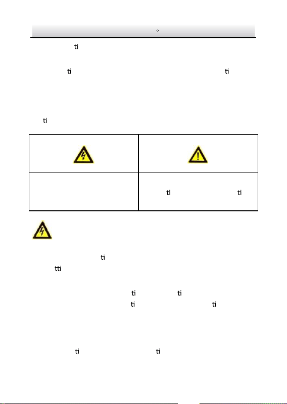
The precau
on measure is divided into “Warnings” and “Cau ons”
Warnings: Serious injury or death may occur if any of the warnings
are neglected.
Cautions: Injury or equipment damage may occur if any of the
cau
ons are neglected.
Warnings
● Proper configura on of all passwords and other security
se
ngs is the responsibility of the installer and/or end-user.
● In the use of the product, you must be in strict compliance with
the electrical safety regula
ons of the na on and region. Please
refer to technical specifica
ons for detailed informa on.
● Input voltage should meet both the SELV (Safety Extra Low
Voltage) and the Limited Power Source with 12 VDC according
to the IEC60950-1 standard. Please refer to technical
specifica
ons for detailed informa on.
Warnings Follow these
safeguards to prevent serious
injury or death.
Cautions Follow these
precau
ons to prevent poten al
injury or material damage.
Network Turret Camera·Quick Start Guide
5
● Do not connect several devices to one power adapter as
adapter overload may cause over-hea
ng or a fire hazard.
● Please make sure that the plug is firmly connected to the power
socket. When the product is mounted on wall or ceiling, the
device shall be firmly fixed.
● If smoke, odor or noise rise from the device, turn off the power
at once and unplug the power cable, and then please contact
the service center.
Cautions
● Make sure the power supply voltage is correct before using the
camera.
● Do not drop the camera
or subject it to physical shock.
● Do not touch sensor modules with fingers. If cleaning is
necessary, use clean cloth with a bit of ethanol and wipe it
gently. If the camera will not be used for an extended period,
please replace the lens cap to protect the sensor from dirt.
● Do not aim the camera at the sun or extra bright places.
Bl
ooming or smearing may occur otherwise (which is not a
malfunc
on), and affect the endurance of sensor at the same
me.
● The sensor may be burned out by a laser beam, so when any
laser equipment is in using, make sure that the surface of
sensor will not be exposed to the laser beam.
● Do not place the camera in extremely hot, cold (the opera
ng
temperature shall be-30°C ~+60°C, or -40°C ~ +60°C if the
Network Turret Camera·Quick Start Guide
6
camera model has an “H” in its suffix), dusty or damp loca ons,
and do not expose it to high electromagne
c radia on.
● To avoid heat accumula
on, good ven la on is required for
opera
ng environment.
● Keep the camera away from liquid while in use.
● While in delivery, the camera shall be packed in its original
packing, or packing of the same texture.
● Regular part replacement: a few parts (e.g. electroly
c
capac
itor) of the equipment shall be replaced regularly
according to their average enduring
me. The average e
varies because of differences between opera
ng environment
and using history, so regular checking is recommended for all
the users. Please contact with your dealer for more details.
● Improper use or replacement of the ba
ery may result in
hazard of explosion. Replace with the same or equivalent type
only. Dispose of
used ba
eries according to the instruc ons
provided by the ba
ery manufacturer.
● If the product does not work properly, please contact your
dealer or the nearest service center. Never a
empt to
disassemble the camera yourself. (We shall not assume any
responsibility for problems caused by unauthorized repair or
maintenance.)

Network Turret Camera·Quick Start Guide
7
Table of Contents
1 Appearance Description ..............................................................8
....................................................................................
2 Installation 10
3 Setting the Network Camera over the LAN ............................. 19
Wiring ........................................................................... 19 3.1
Ac
va ng the Camera ................................................... 20 3.2
Ac
va on via Web Browser ................................ 203.2.1
Ac
va on via SADP So ware ............................. 213.2.2
Modifying the IP Address ...............................
........................................................
............... 23
3.3
4 Accessing via Web Browser 26
5 Quick Operation Guide (German Version) 28
...............................
Network Turret Camera·Quick Start Guide
8
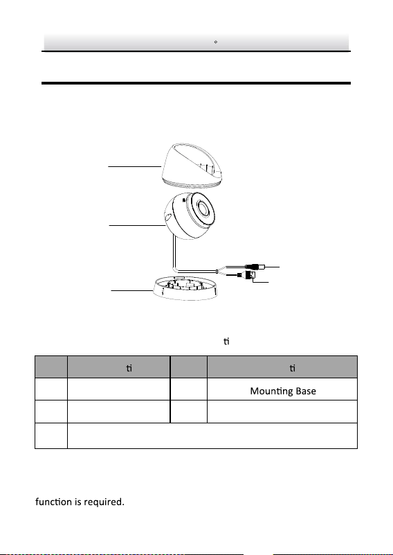
1 Appearance Description
This camera series of turret camera has four appearance types.
1.1 Type I
Overview of Type I Turret Camera Figure 1-1
Descrip
on Table 1-1
No. Descrip on No. Descrip on
1 Enclosure 3
Power Cord
2 Camera Body 4
5
Network Cable
Note:
For cameras support power over Ethernet (PoE), the power is passed
along with data on Ethernet cabling. And a switch supports PoE
1
2
3
4
5
Network Turret Camera·Quick Start Guide
9
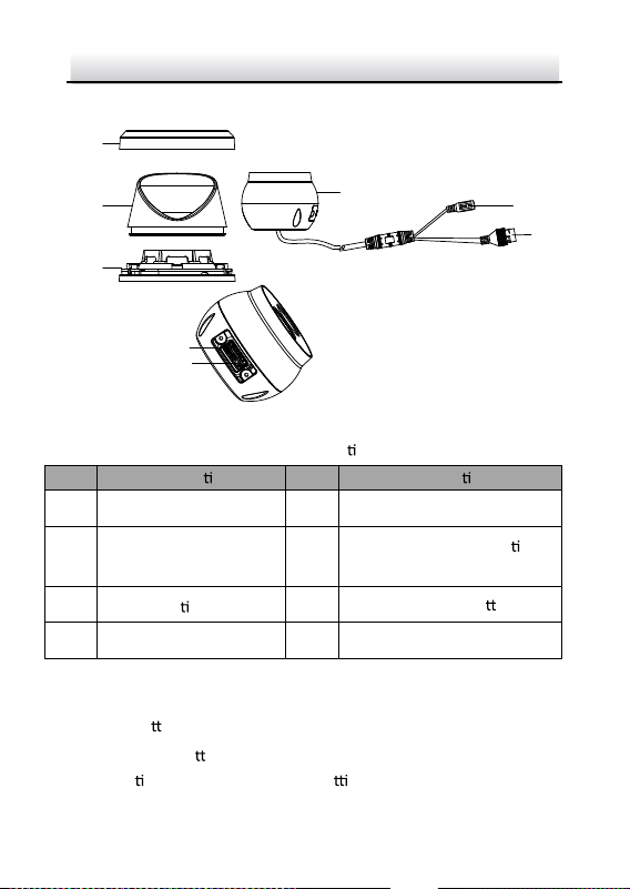
1.2 Type II
1
2
3
4
5
6
8
7
Type I Turret Camera Figure 1-2
Descrip
on Table 1-2
No.
Descrip on
No
Descrip on
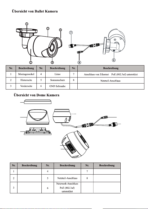
1 Trim Ring 5 Power Cord
2 Enclosure 6
10M/100M self-adap
ve
Ethernet interface (PoE)
3 Moun ng Base 7
RST (Reset) Bu
on
4 Camera 8
Memory Card Slot
Notes:
● For this type I camera, the layout of memory card slot and
reset bu
on may be different from model to model.
● Press Reset bu
on about 10s when the camera is power on or
reboo
ng to restore the default se ngs, including the user
name, password, IP address, port No., etc.
Network Turret Camera·Quick Start Guide
10
2 Installation
Before you start:
● Make sure the device in the package is in good condi
on and all
the assembly parts are included.
● The standard power supply is 12 VDC, please make sure your
power supply matches with your camera.
● Make sure all the related equipment is power-off during the
installa
on.
● Check the specifica
on of the products for the installa on
environment.
● Make sure that the wall is strong enough to withstand four
mes the weight of the camera and the bracket.
For the camera that supports IR, you are required to pay a
en on to
the following precau
ons to prevent IR reflec on:
● Make sure that there is no reflec
ve surface too close to the
camera lens. The IR light from the camera may reflect back into
the lens causing reflec
on.
2.1 Ceiling Moun
Before you start:
2.1.1 Type l
Both wall moun
ng and ceiling moun ng are suitable for the
turret
camera. Ceiling moun
ng will be taken as an example in this sec on.
Network Turret Camera·Quick Start Guide
11
And you can take steps of ceiling moun ng as a reference for wall
moun
ng.
Steps:
1. Paste the drill template (supplied) to the desired moun
ng
posi
on on the ceiling.
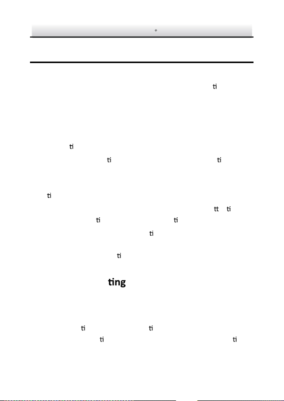
2. Drill the screw holes and the cable hole in the ceiling according to
the drill template.
Note:
Drill the cable hole, if adop
ng ceiling outlet to route the cable.
Φ 85 mm (3
.35
"
)
Φ110 mm
(
4
.
33")
3-Φ 4.2 mm
(0.
17
")
Φ 20 mm
(0.79")
Screw
Hole
Cable
Hole
Figure 2-1 The Drill Template
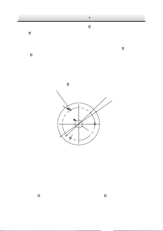
3. Disassemble the camera.
1). Rotate the camera to align the notch to one of the marks.
2). Insert a coin or another similar tool to the notch.
3). Press down the coin or another similar tool to pry the
moun
ng base so as to separate the moun ng base from the
camera.
Network Turret Camera·Quick Start Guide
12
Mark
Notch
Figure 2-2 Disassemble the Camera
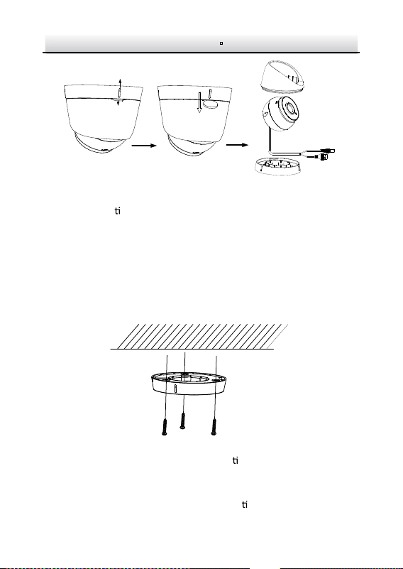
4. Fix the moun
ng base to the ceiling with supplied screws.
Notes:
In the supplied screw package, both self-tapping screws, and
expansion bolts are contained.
If the ceiling is cement, expansion bolts are required to fix the
camera. If the ceiling is wooden, self-tapping screws are
required.
Figure 2-3 Fix the Moun
ng Base
5. Route the cables through the cable hole or the side opening.
6. Install the camera body back to the moun ng base.
Network Turret Camera·Quick Start Guide
13
Figure 2-4 Install the Camera Body
7. Connect the power cord and network cable.
8. Power on the camera, and set the network configura on (for
details, refer to 3 Se
ng the Network Camera over the LAN and 4
Accessing via Web Browser) to check whether the image is go
en
from the op
um angle. If not, adjust the surveillance angle.
0° to 360°
0° to 360°
0° to 75°
Figure 2-5 Adjust Surveillance Angle
1). Hold the camera body and rotate the enclosure to adjust the
pan angle [0° to 360°].

Network Turret Camera·Quick Start Guide
14
2). Move the camera body up and down to adjust the lt angle [0°
to 75°].
3). Rotate the camera body to adjust the rota
on angle [0° to
360°].
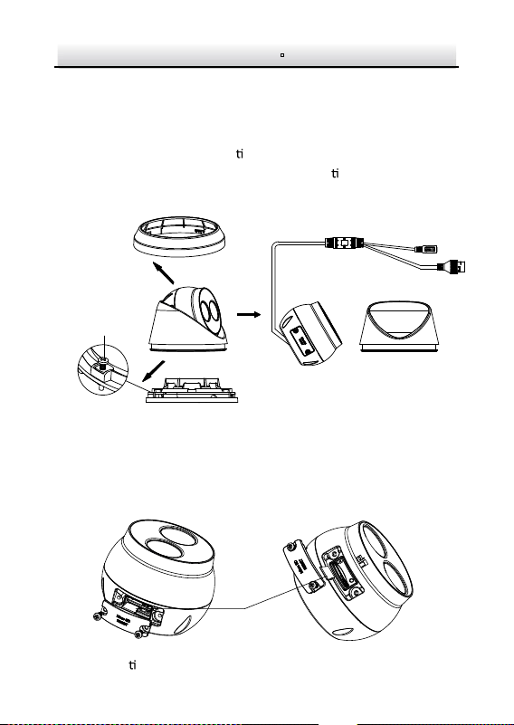
2.1.2 Type II
Steps:
Disassemble the camera. 1.
1). Rotate the trim ring an clockwise to take it off from the camera.
Network Turret Camera·Quick Start Guide
15
2). Loosen the fixing screw. Take the moun ng base off from the
camera and the enclosure.
3). Separate the camera and the enclosure.
①
②
③
Fixing Screw
Disassemble the Camera Figure 2-6
Install memory card If the IP camera is used with a video recorder, . 2.
1). Unscrew the memory card slot cover.
2).
Insert the memory card.
Memory Card
Install Memory Card Figure 2-7
3). (Op onal) to unmount the memory card, push to get it
ejected.
the video recorder can directly record videos. And you don’t need
to insert a TF card. If you use the IP camera alone, you need to
insert a TF card before recording videos.
Network Turret Camera·Quick Start Guide
16
4). Screw the memory card slot cover back.
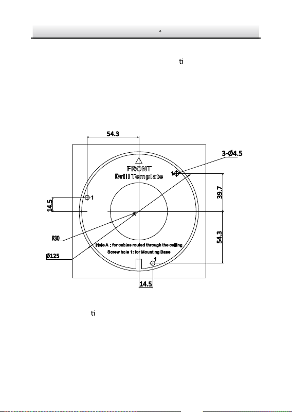
Paste the drill template to desired moun
ng place. 3.
Drill the screw holes (for expansion screws) and the cable hole 4.
on the ceiling according to the drill template.
Note:
If the camera is installed to a wooden wall, use self-tapping
screws instead of expansion screws.
Drill Template Figure 2-8
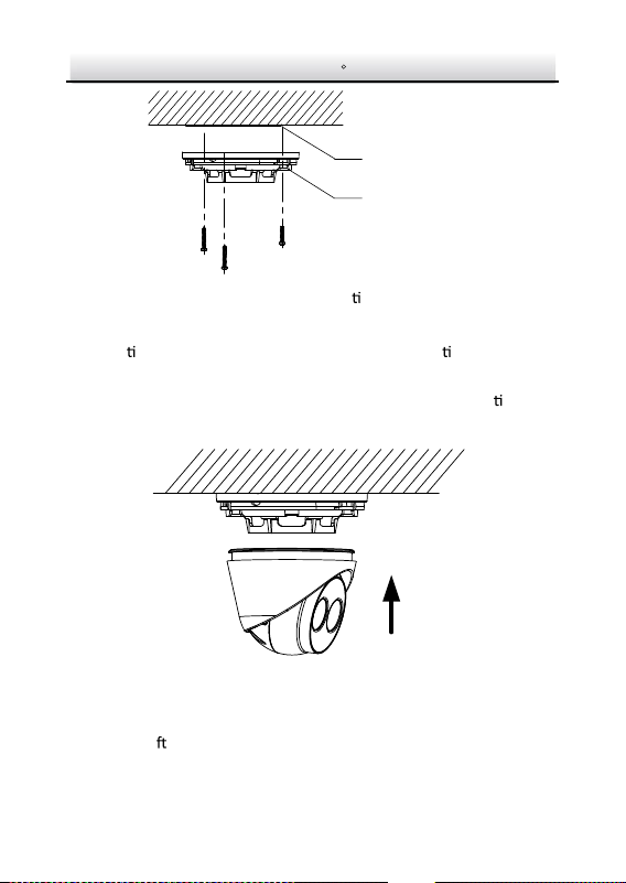
Fix the moun
ng base to the ceiling with two supplied screws. 5.
Network Turret Camera·Quick Start Guide
17
Drill Template
Mounting Base
Fix Moun
ng Base Figure 2-9
Connect the corresponding power/network cable. Refer to the 6.
sec
on 2.3 for the water-proof accessory installa on if the
camera is installed in the outdoor.
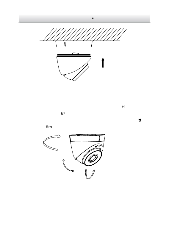
Install the camera along with the enclosure to the moun
ng 7.
base.
Install the Camera Figure 2-10
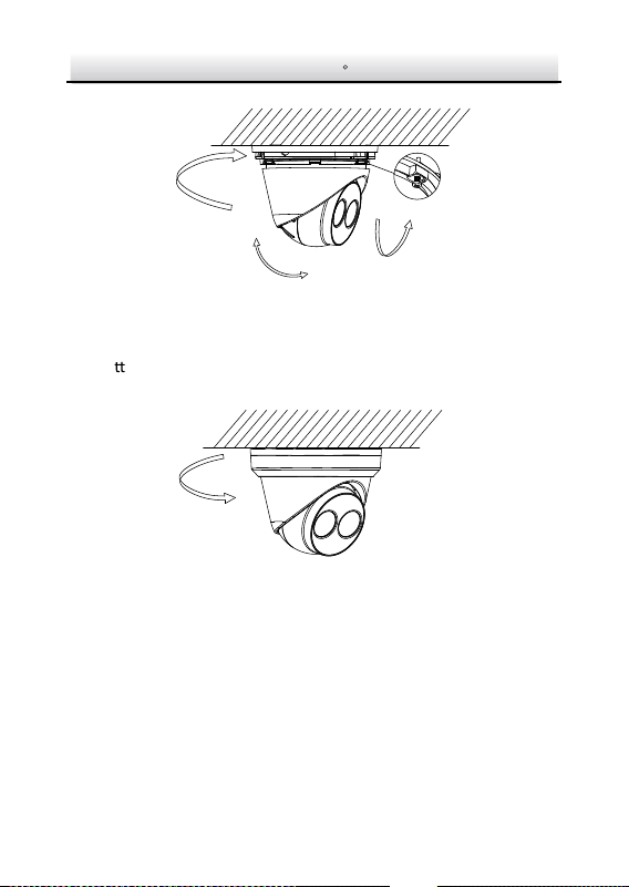
Adjust the surveillance angle of the camera. Secure the fixing 8.
screw a
er adjustment.
Network Turret Camera·Quick Start Guide
18
Pan:
0° to 360°
Tilt:
0° to 75°
Rotate:
0° to 360°
Adjust Surveillance Angle Figure 2-11
A
ach the trim ring to the camera and rotate the trim ring 9.
clockwise to get it secured.
Figure 2-12 Install Trim Ring
Network Turret Camera·Quick Start Guide
19
3 Setting the Network Camera over the
LAN
Note:
You shall acknowledge that the use of the product with Internet
access might be under network security risks. For avoidance of any
network a
acks and informa on leakage, please strengthen your
own protec
on.
If the product does not work properly, contact your dealer or the
nearest service center for help.
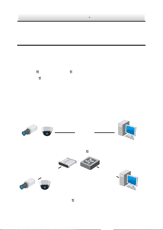
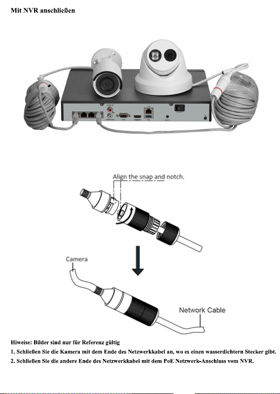
Wiring 3.1
Connect the camera to network according to the following figures.
半球
Network Cable
or
Network Camera
Computer
Connec
ng Directly Figure 3-1
网络交换机
半球
Network Cable
Network Cable
or
or
Network Camera
Computer
Connec
ng via a Switch or a Router Figure 3-2
Network Turret Camera·Quick Start Guide
20
Activating the Camera 3.2
You are required to ac vate the camera first by se ng a strong
password for it before you can use the camera.
Ac
va on via Web Browser, Ac va on via SADP, and Ac va on via
Client So
ware are all supported. We will take ac va on via SADP
so
ware and Ac va on via Web Browser as examples to introduce
the camera ac
va on.
Note:
Refer to the User Manual of Network Camera for Ac
va on via
Client So
war
e.
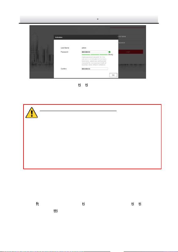
Activation via Web Browser 3.2.1
Steps:
1. Power on the camera. Connect the camera to your computer or
the switch/router which your computer connects to.
2. Input the IP address into the address bar of the web browser, and
press Enter to enter the ac
va on interface.
Notes
:
The default IP address of the camera is 192.168.1.64.
The computer and the camera should belong to the same
subnet.
For the camera enables the DHCP by default, you need to use
the SADP so
ware to search the IP address.
Network Turret Camera·Quick Start Guide
21
Ac
va on Interface(Web) Figure 3-3
3. Create a password and input the password into the password
field.
STRONG PASSWORD RECOMMENDED– We highly
recommend you create a strong password of your own
choosing (using a minimum of 8 characters, including
upper case letters, lower case letters, numbers, and
special characters) in order to increase the security of
your product . And we recommend you reset your
password regularly, especially in the high security
system, resetting the password monthly or weekly can
better protect your product.
4. Confirm the password.
5. Click OK to save the pass
word and enter the live
view interface.
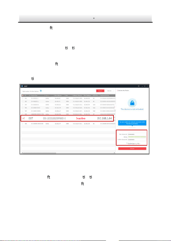
Activation via SADP Software 3.2.2
SADP so ware is used for detec ng the online device, ac va ng the
camera, and rese
ng the password.
Network Turret Camera·Quick Start Guide
22
Get the SADP so ware from the supplied disk or the official website,
and install the SADP according to the prompts. Follow the steps to
activate the camera, please refer to the User Manual of Network
Camera for other two ac va on methods.
Steps:
1. Run the SADP so
ware to search the online devices.
2. Check the device status from the device list, and select the
inac
ve device.
Select inactive device.
Input and confirm
password.
SADP Interface Figure 3-4
Note:
The SADP so
ware supports ac va ng the camera in batch. Refer
to the user manual of SADP so
ware for details.
3. Create and input the new password in the password field, and
confirm the password.
Network Turret Camera·Quick Start Guide
23
STRONG PASSWORD RECOMMENDED– We highly
recommend you create a strong passwordof your own
choosing (using a minimum of 8 characters, including
upper case letters, lower case letters, numbers, and
special characters) in order to increase the security of
your product. And we recommend you r eset your
password regularly , especially in the high security
system, resetting the password monthly or weekly can
better protect your product.
4. Click Activate to start ac
va on.
You can check whether the ac
va on is completed on the popup
window. If ac
va on failed, make sure that the password meets
the requirement and try again.
Modifying the IP Address 3.3
Purpose:
To view and configure the camera via LAN (Local Area Network), you
need to connect the network camera in the same subnet with your
PC.
Use the SADP so
ware or client so
ware to search and change the
IP address of the device. We take modifying the IP Address via SADP
so
ware as an example to introduce the IP address modifica on.
For IP address modifica
on via client so ware, refer to the user
manual of client so
ware.
Network Turret Camera·Quick Start Guide
24
Steps:
1. Run the SADP so
ware.
2. Select an ac
vate device.
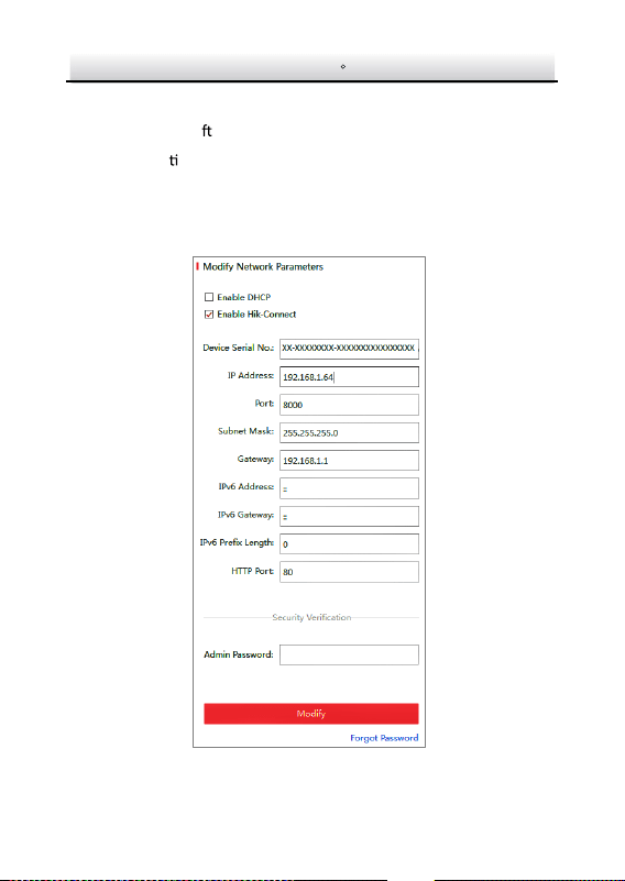
3. Change the device IP address to the same subnet with your
computer by either modifying the IP address manually or checking
the checkbox of Enable DHCP.
Modify the IP Address Figure 3-5

Network Turret Camera·Quick Start Guide
25
4. Input the admin password and click Modify to ac vate your IP
address modifica
on.
The batch IP address modifica
on is supported by the SADP. Please
refer to the User Manual of SADP for details.

Network Turret Camera·Quick Start Guide
26
4 Accessing via Web Browser
System Requirement:
Opera
ng System: Microso Windows XP SP1 and above version
CPU: 2.0 GHz or higher
RAM: 1G or higher
Display: 1024×768 resolu
on or higher
Web Browser: Internet Explorer 8.0 and above version, Apple Safari
5.0.2 and above version, Mozilla Firefox 5.0 and above version and
Google Chrome 18 and above version
Steps:
1. Open the web browser.
2. In the browser address bar, input the IP address of the network
camera, an
d press the Enter key to enter the login interface.
Note:
The default IP address is 192.168.1.64. You are recommended
to change the IP addre
ss to the same subnet with your
computer.
3. Input the user name and password.
The admin user should configure the device accounts and
user/operator permissions properly. Delete the unnecessary
accounts and user/operator permissions.
Note:
The device IP address gets locked if the admin user perf
orms 7
failed password a
empts (5 a empts for the user/operator).
Network Turret Camera·Quick Start Guide
27
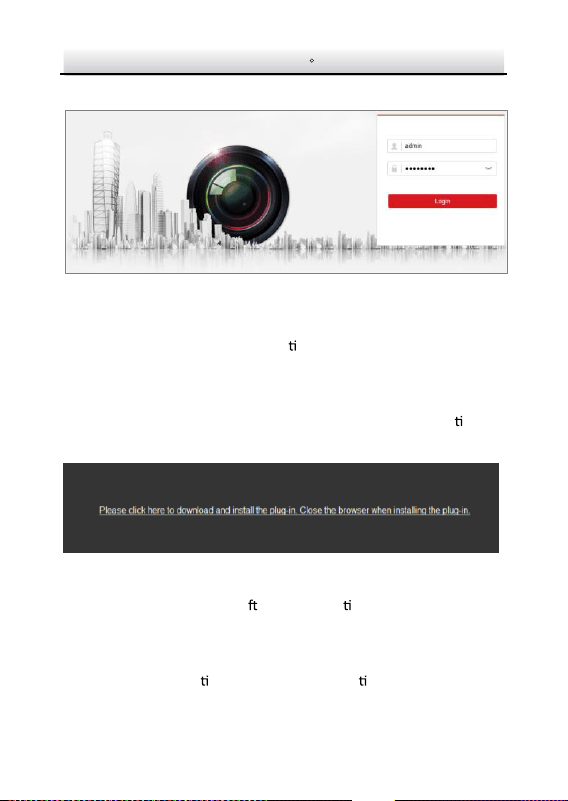
4. Click Login.
Login Interface Figure 4-1
5. Install the plug-in before viewing the live video and managing the
camera. Please follow the installa
on prompts to install the
plug-in.
Note:
You may have to close the web browser to finish the installa
on of
the plug-in.
Download Plug-in Figure 4-2
6. Reopen the web browser a
er the installa on of the plug-in and
repeat steps 2 to 4 to login.
Note:
For detailed instruc
ons of further configura on, please refer to
the user manual of network camera.
Turret
1
2
3
4
5
9
6
8
7
Zierring
Gehege
RST-Taste (Reset)
Speicherkartensteckplatz
9
Befestigungsbasis
Kamera
29
30