システム拡張
ユーザーガイド
日本語
System Expansion
User Guide
English
Expansión del sistema
Guía de usuario
Español
Руководство
пользователя
системы
расширения
Русский ㆶ։ѣᮽ
Extension du système
Guide d´utilisation
Français
Systemerweiterung
Benutzerhandbuch
Deutsch
Espansione del sistema
Guida utente
Italiano
DIM-1321-000C
© CANON INC. 2024
Ver. 1.3
XF / XA
൞ֵ⭞ᵢӝҁࢃθ䈭ࣗᗻݾԊ㓼䰻䈱ᵢֵ⭞䈪᱄ҜȾ
䈭ࣗᗻؓ㇗ླᵢҜθԛᰛ㜳䳅ᰬḛ䰻 ؓ⮏༽⭞ Ⱦ
䈭൞ݻ࠼⨼䀙ᇯⲺะрθ↙⺤ֵ⭞Ⱦ
系统扩展用户指南

はじめに
3
JP
はじめに
本書は、キヤノン製ビデオカメラ(以降、カメラと記載する)に対応した別売アクセサリーの互換性や使い
かたについて紹介するユーザーガイドです。ご使用の前に、必ず製品に付属の説明書と本書をよくお読みの
うえ、正しくお使いください。
使う前に知っておいてください
別売アクセサリーの電源は、特別な記載がない限り、カメラから供給されます。
お使いのカメラによっては、本書で紹介している機能に対応していない場合があります。お使いのカメラ
の使用説明書も併せてご覧ください。
本書の操作手順で紹介しているアクセサリーや工具などは、一部のカメラ(モデル)に付属していること
があります。詳細については、お使いのカメラの使用説明書をご覧ください。アクセサリーに工具が付属
していることもあります。カメラやアクサセリーに工具が付属していないときは、市販の工具をお使いく
ださい。
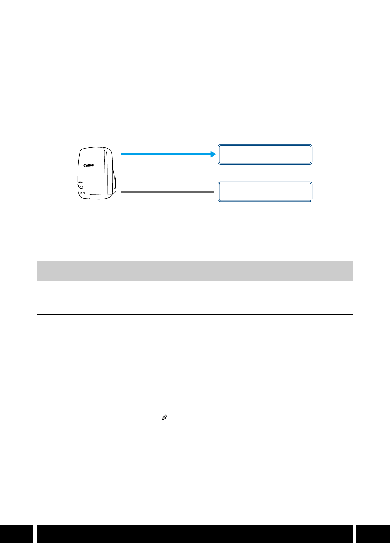
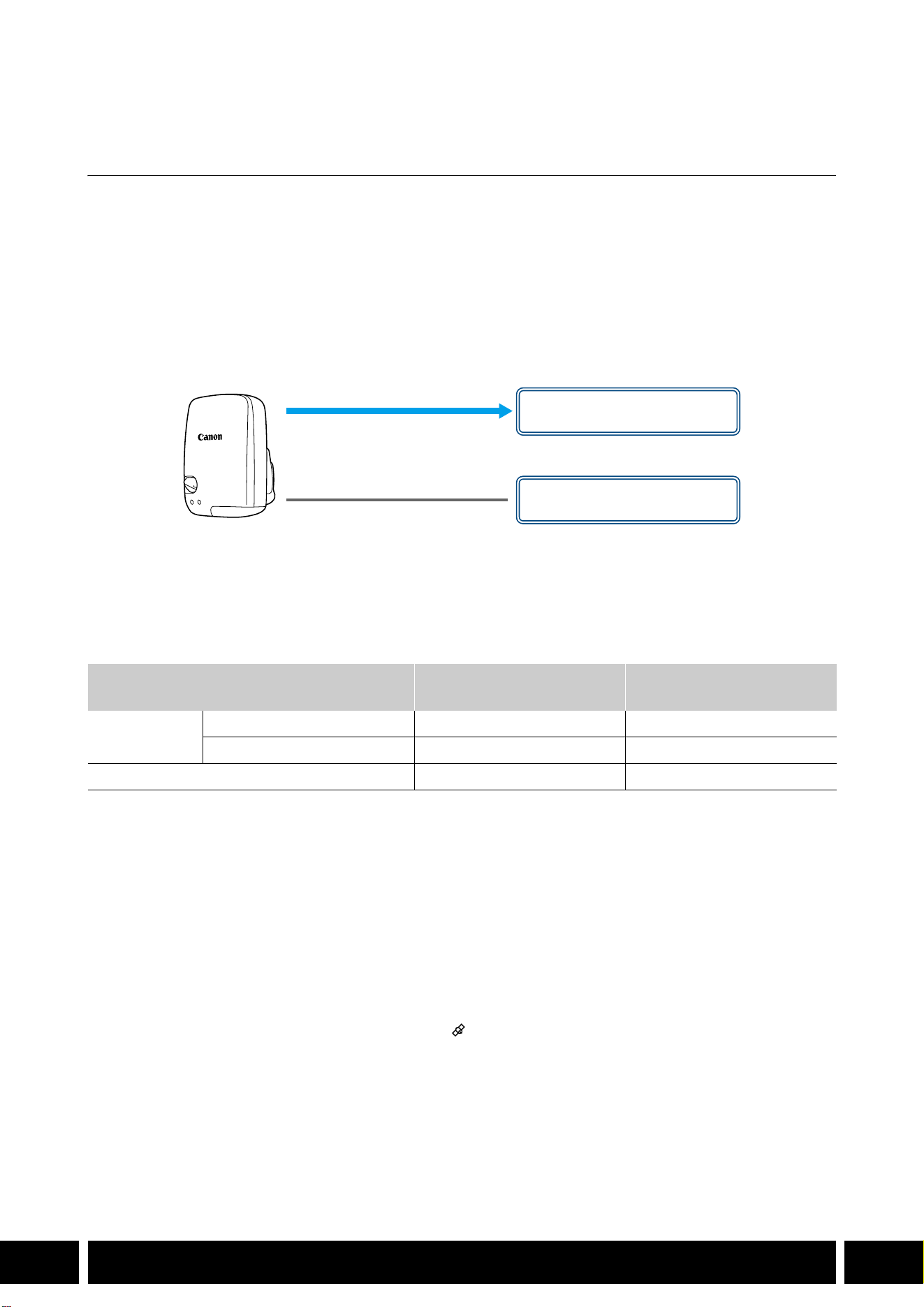
B本書の読みかた
本書で使用するアイコンや表記の意味は次のとおりです。
本書に記載している別売アクセサリーの仕様に関する注意事項など
(メモ)知っておいていただきたいことや追加情報など
0 参照ページを示す
カメラ キヤノン製ビデオカメラのこと
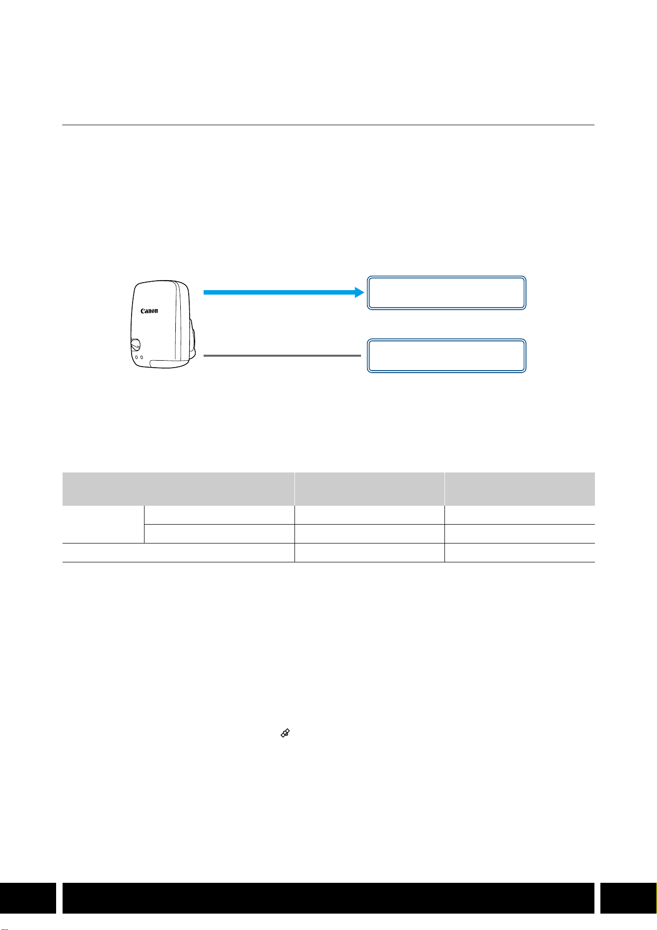
本書はマルチ言語です。ページ右下の言語コードをクリックすると、その言語の先頭
ページ(目次)に移動できます。
カメラやアクセサリーが落下しないように、机などの安定した所で取り付けや調節を行ってくだ
さい。
対応していないカメラには接続しないでください。
JP
本書の記載内容は 2024 年 1 月現在のものです。製品の仕様および外観や本書の記載内容は、改良等のため
予告なく変更することがあります。ご了承ください。
本書に記載しているアクセサリーとカメラの対応表
4
JP
本書に記載しているアクセサリーとカメラの対応表
製品の機能を拡張する主なアクセサリーについて記載しています。
*1
詳細については、カメラの使用説明書とアクセサリーの説明書をご覧ください。
*2
この装置は,クラス A 機器です。この装置を住宅環境で使用すると電波妨害を引き起こすことがあります。この場合に
は使用者が適切な対策を講ずるよう要求されることがあります。
別売アクセサリー
XF705 XF605
XA75 /
XA70
XA60 XA55 XA40 A
通信
GPSレシーバー GP-E2
NNNNNN5
機能拡張/レンズ対応
リモートコントローラー RC-V100
NNNNNN−
*1
リモートカメラコントローラー
RC-IP100
*2
/ RC-IP1000
*2
N −
*1
ワイヤレスコントローラー WL-D89
N −
*1
ワイヤレスコントローラー WL-D6000
N −
*1
テレコンバーター TL-H58 / TL-U58
TL-U58 TL-U58 TL-U58 TL-H58 TL-U58 TL-H58
7
ワイドアタッチメント WA-H58 / WA-U58
WA-U58 WA-U58 WA-U58 WA-H58 WA-U58 WA-H58
9
撮影スタイル/構成
ハンドルユニット HDU-1 / HDU-3
HDU-3 HDU-1
12
通信
5
JP
通信
GPS レシーバー GP-E2
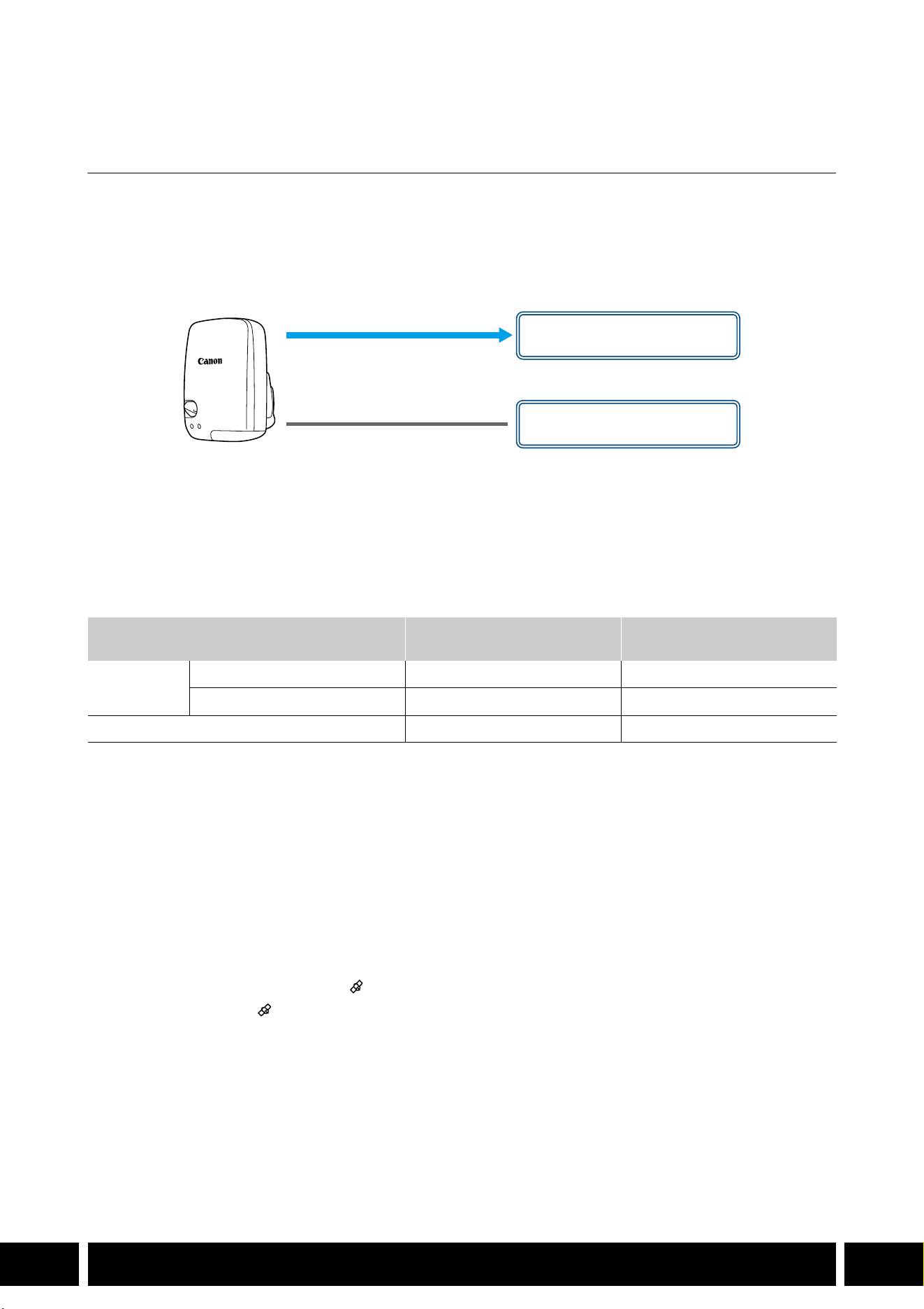
カメラのマルチアクセサリーシューまたは USB端子に GPSレシーバー GP-E2 を接続して撮影すると、ク
リップや静止画のメタデータに
GPSから取得した位置情報(経度、緯度、標高。以下、「GPS 情報」)などを
記録できます。カメラの USB 端子に接続して撮影するときは、GP-E2付属の携帯用ケースに入れ、カメラの
グリップベルトまたは腰に取り付けて使用することをおすすめします。
GP-E2 を使用するには単 3 形電池が
必要です。
GP-E2の取り付けかたや機能の詳細については、GP-E2の説明書をご覧ください。
カメラの
USB端子が Type-C のときは、別売のインターフェースケーブル IFC-40AB IIIまたは IFC-150AB IIIが
必要です。また、カメラによっては、カメラの
USB 端子のメニュー設定が必要な場合があります。詳細に
ついては、お使いのカメラの使用説明書をご覧ください。
記録される情報
* Canon XF Utilityで、GPS 情報を使ってクリップを検索することができる。
GPS レシーバーを接続して有効にする
1. GP-E2 の電源を切る
2. GP-E2 をカメラに接続する
カメラのマルチアクセサリーシュー、または付属の接続ケーブルや別売のインターフェースケーブル
を使ってカメラの
USB端子に接続する。
3. GP-E2 の電源を入れる
GPS 機能が有効になる。画面に が点滅表示されて、GPS衛星を探索する。
衛星を捕捉すると が点灯し、以降に記録するクリップ/静止画に GPS 情報が付加される。
記録方式
GPS情報
(経度、緯度、標高)
協定世界時
(UTC)
動画
MP4
●●
XF-AVC*
●
−
静止画 ● ●
接続ケーブル(GP-E2に付属)
USB端子
(直接取り付ける)
マルチアクセサリーシュー
または

通信
6
JP
GP-E2をカメラのマルチアクセサリーシューと USB端子に同時に接続しないでください。
GPSレシーバーは、使用する国/地域の法令等の規制に従って使用してください。国/地域に
よっては
GPS の使用などが規制されていることがあります。国外で使用するときは特にご注意く
ださい。
電子機器の使用が制限されている場所での使用には十分ご注意ください。
動画や静止画に記録される GPS情報には、個人を特定する情報が含まれていることがあります。
そのため
GPS 情報が記録された動画や静止画を他人に渡したり、インターネットなどの不特定多
数の人々が閲覧可能な環境に掲載したりするときは、十分ご注意ください。
GPSレシーバーは、磁石やモーターの近くなど強い磁気を発生する場所には絶対に置かないでく
ださい。
動画に記録される GPS情報は、撮影開始時点の位置情報です。
GPSから取得した時刻情報を使って、カメラの日時を自動的に設定できます。お使いのカメラの
使用説明書に記載しているシステム設定メニュー一覧をご覧ください。
バッテリーなどの電源を交換したときや本機の電源を切ったときは、GPS衛星からの信号の受信
に時間がかかることがあります。
カメラの端子に接続したケーブルやユニットケーブルを、GPS レシーバーの近くに配置しないで
ください。
GPS 情報に影響することがあります。
ステータス画面を表示できるカメラは、GPS から取得した位置情報や衛星捕捉状態、信号強度な
どをステータス画面で確認できます。詳細については、お使いのカメラの使用説明書をご覧くだ
さい。
GP-E2の次の機能には対応していません。
–自動時刻設定の「今すぐ実行」
–電子コンパス
–設定した間隔で位置情報を更新する
機能拡張/レンズ対応
7
JP
機能拡張/レンズ対応
テレコンバーター TL-H58 / TL-U58
テレコンバーター TL-H58 / TL-U58 をお使いいただくと、1.5 倍に拡大して撮影できます。カメラによって
は、手ブレ補正のしかたや最至近撮影距離が変わります。詳細については、お使いのカメラの使用説明書を
ご覧ください。
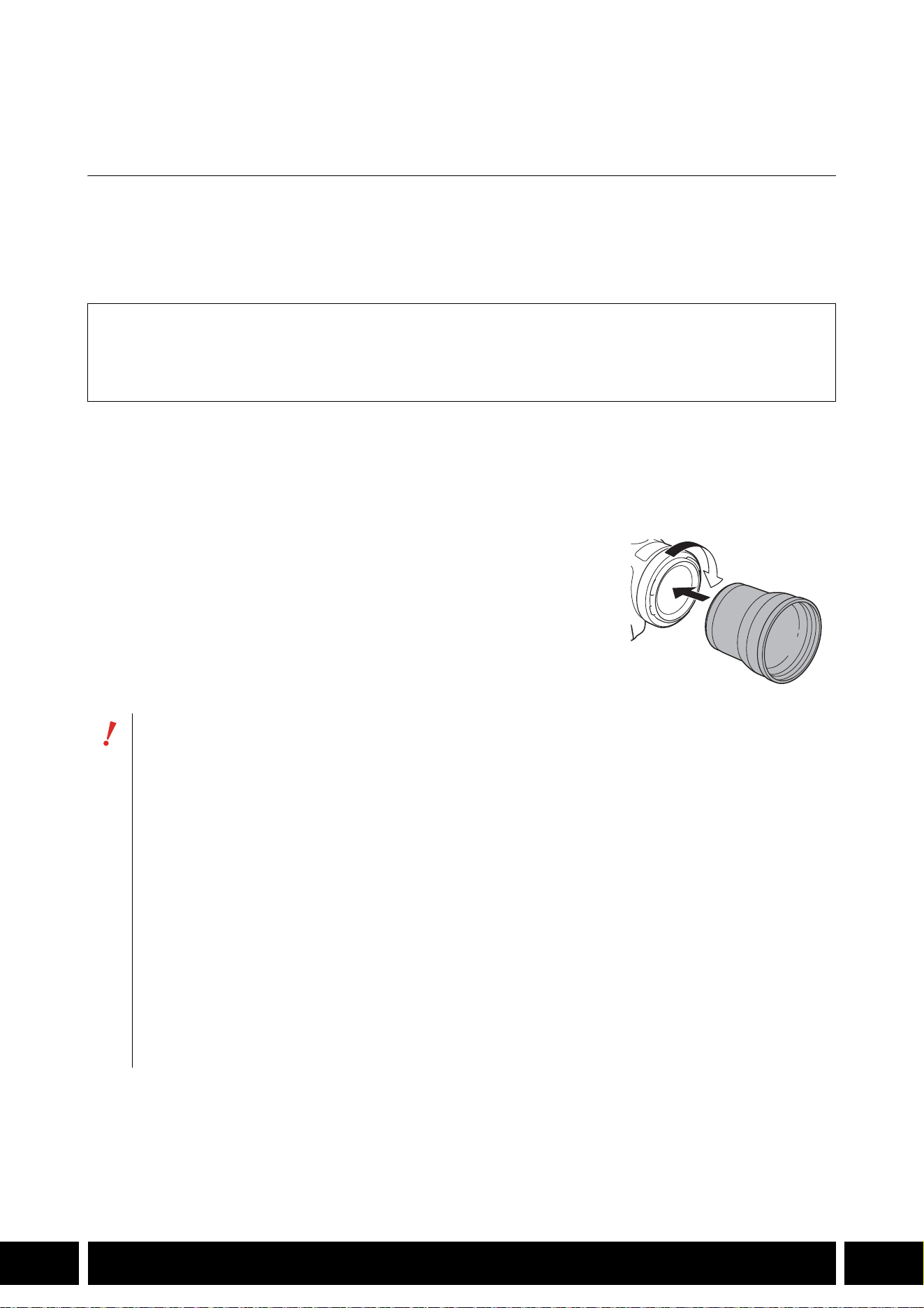
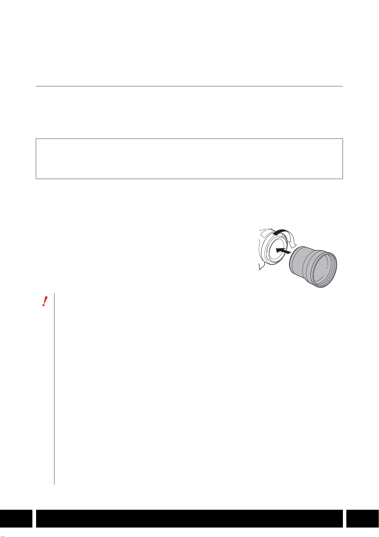
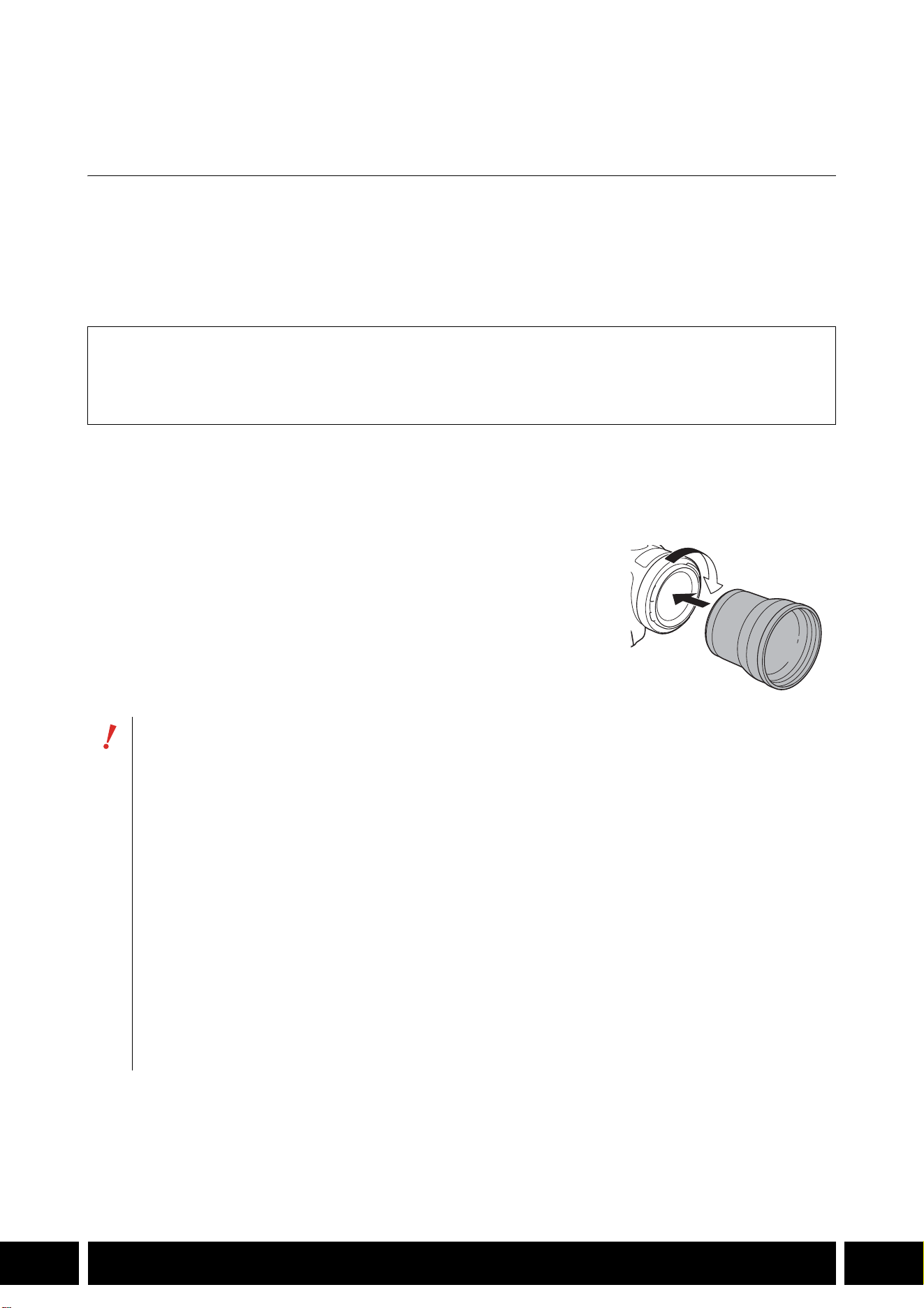
カメラに取り付ける
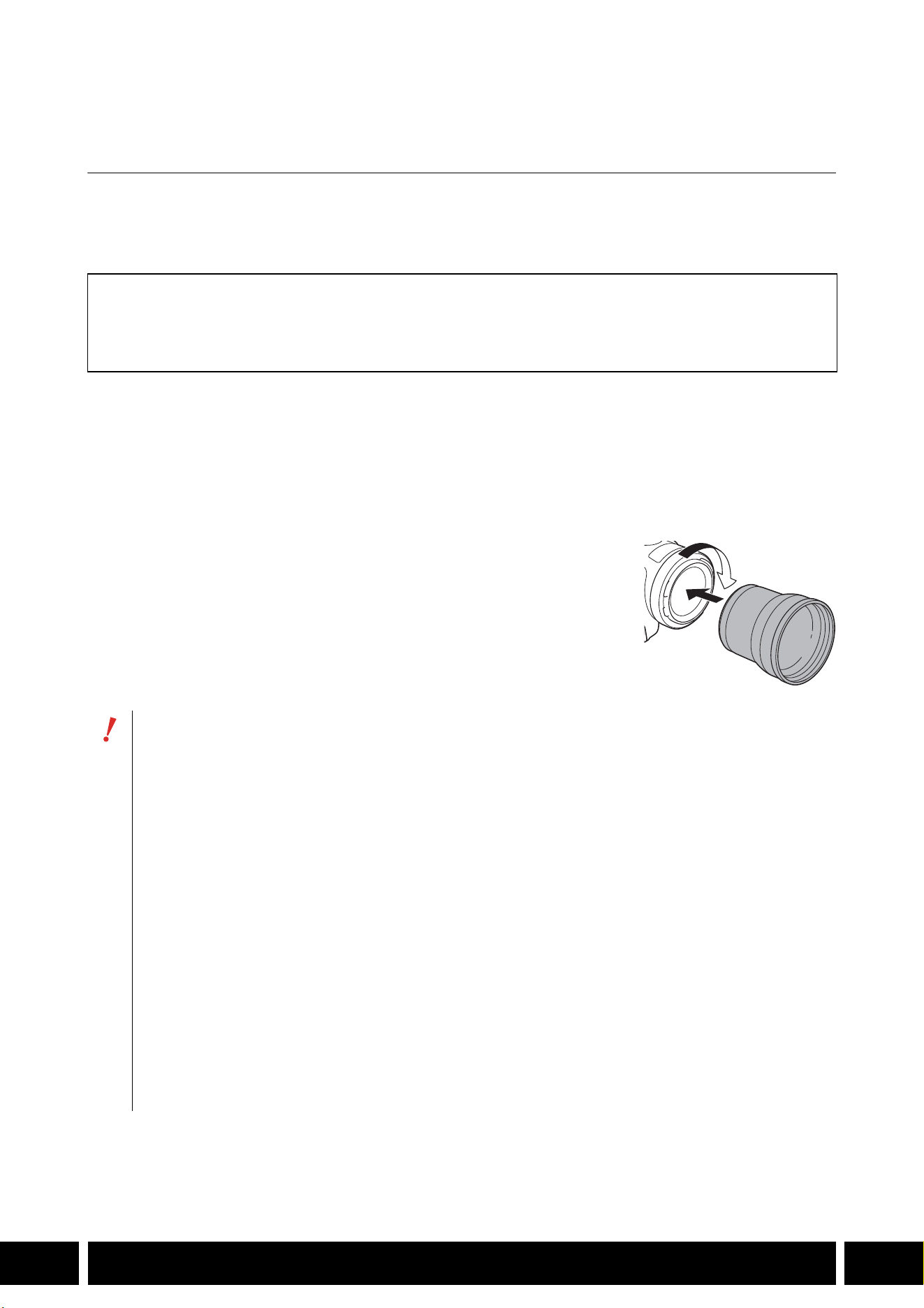
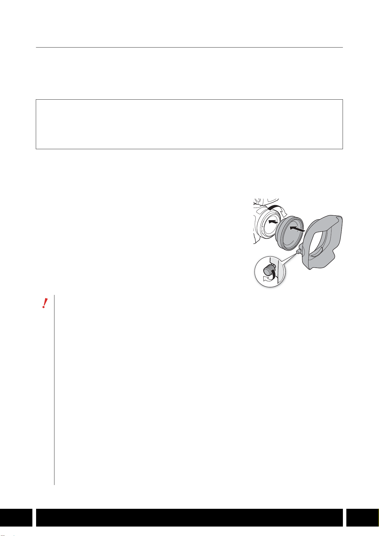
カメラにテレコンバーターを取り付けます。ここでは、TL-U58 の取り付けかたを例にして説明します。
TL-H58 の取り付けかたも同様です。
テレコンバーターをカメラのフィルター取り付けねじに完全にねじ込む
付属品
□ ソフトケース
□
レンズキャップ
□
レンズダストキャップ
カメラに取り付けたときは、レンズを太陽に向けないでください。カメラが故障する恐れがあり
ます。
テレコンバーターとカメラのレンズフードやフィルターは、同時に使用できません。
撮影中は手ブレをおこしやすいので、三脚などをご使用ください。
ご使用前に、テレコンバーターとカメラのレンズのゴミをブロアなどで、完全に取り除いてくだ
さい。表面のゴミにピントが合うことがあります。
テレコンバーターを使用する場合は、カメラのメニュー設定が必要です。詳細については、お使
いのカメラの使用説明書をご覧ください。
カメラによっては、テレコンバーターを取り付けると、カメラ前面のタリーランプが見えなく
なったり、リモコンの受光範囲が狭くなったり、別売のビデオライトを使用時に影ができること
があります。
テレコンバーターを使用して、ワイド(広角)側の撮影を行った場合、カメラによってはテレビ
の画面周辺部にレンズの枠が写ることがあります。
レンズには指紋がつきやすいので、ご注意ください。
湿度の高い場所で、長期間保管しないでください。カビが生えることがあります。
ホワイトバランスを調整する場合は、テレコンバーターを取り付けてから行うことをおすすめし
ます。

機能拡張/レンズ対応
9
JP
ワイドアタッチメント WA-H58/ WA-U58
ワイドアタッチメント WA-H58 / WA-U58は、より広角側の撮影を行うためのアタッチメントです。カメラ
によっては、手ブレ補正のしかたや最至近撮影距離が変わります。詳細については、お使いのカメラの使用
説明書をご覧ください。
カメラに取り付ける
カメラにワイドアタッチメントを取り付けます。ここでは、WA-U58 の取り付けかたを例にして説明しま
す。
WA-H58の取り付けかたも同様です。
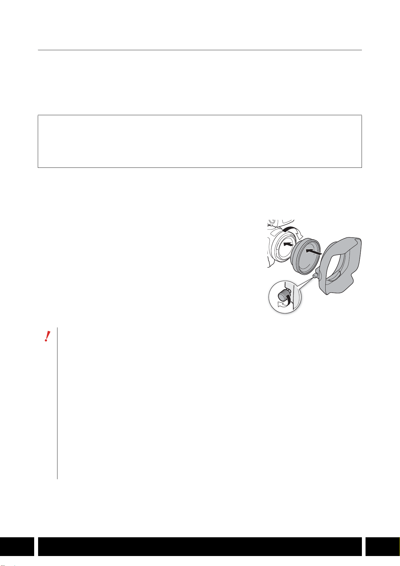
1. カメラのレンズフードをはずして、ワイドアタッチメントをカメラ
のフィルター取り付けねじに完全にねじ込む(햲)
2. ワイドアタッチメントの先端に付属のフードを取り付け、固定ねじ
で固定する(햳)
付属のフードは曲がらないように、まっすぐ取り付ける(曲がっ
ているとフードが映ることがある)。
付属品
□ ソフトケース
□
レンズキャップ
□
レンズダストキャップ
□
フード
ワイドアタッチメントを取り付けると、画面周辺が湾曲して写ることがあります。
ワイドアタッチメントとカメラのレンズフードやフィルターは、同時に使用できません。
ご使用前に、ワイドアタッチメントとカメラのレンズのゴミをブロアなどで、完全に取り除いて
ください。表面のゴミにピントが合うことがあります。
ワイドアタッチメントを使用する場合は、カメラのメニュー設定が必要です。詳細については、
お使いのカメラの使用説明書をご覧ください。
カメラによっては、ワイドアタッチメントを取り付けると、カメラ前面のタリーランプが見えな
くなったり、リモコンの受光範囲が狭くなったり、別売のビデオライトを使用時に影ができるこ
とがあります。
レンズには指紋がつきやすいので、ご注意ください。
保管するときは、必ずレンズキャップを取り付けてください。
湿度の高い場所で、長期間保管しないでください。カビが生えることがあります。
ホワイトバランスを調整する場合は、ワイドアタッチメントを取り付けてから行うことをおすす
めします。
햲
햳
機能拡張/レンズ対応
10
JP
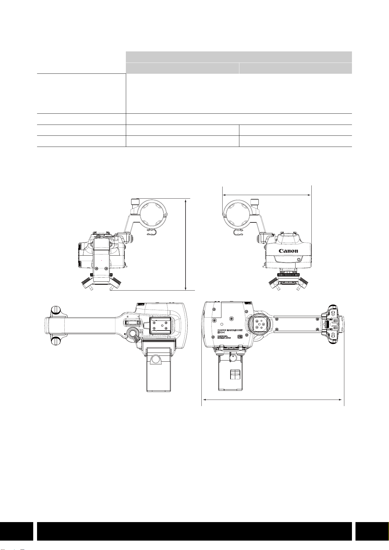
主な仕様
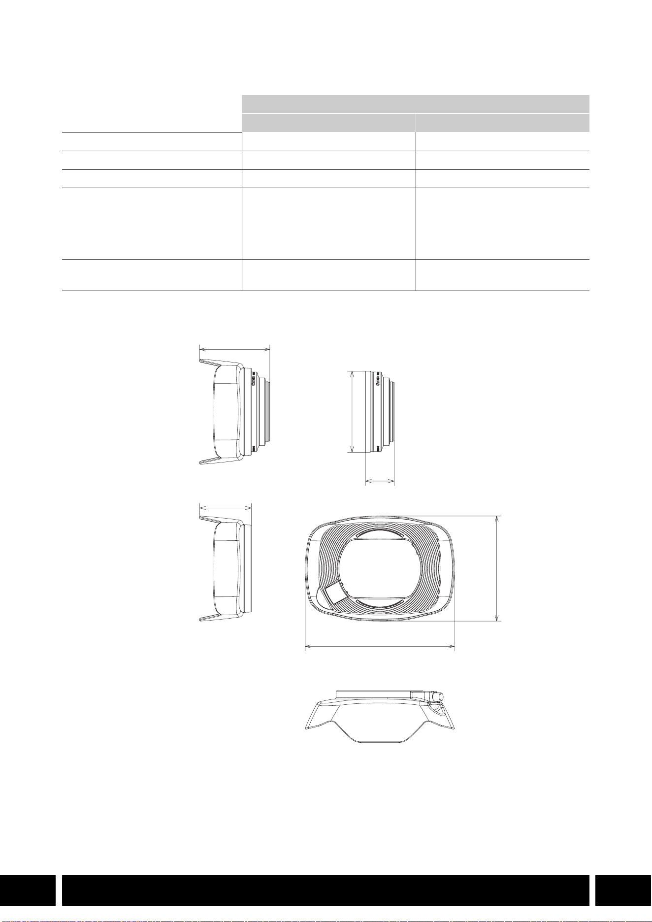
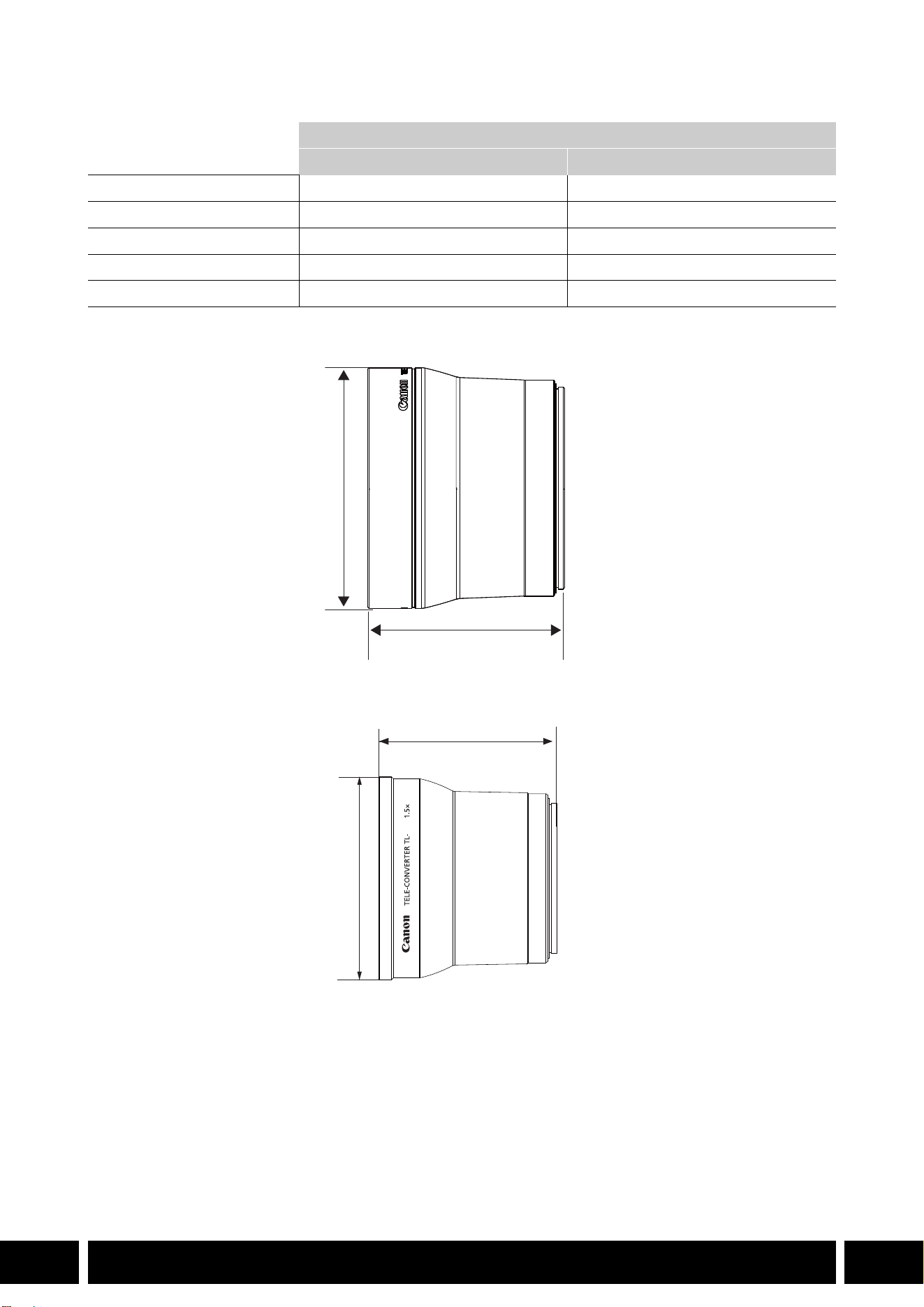
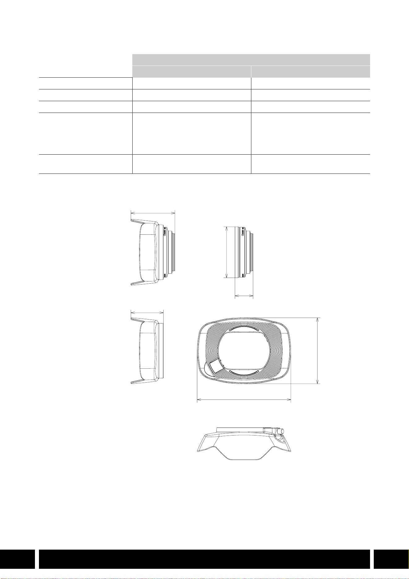
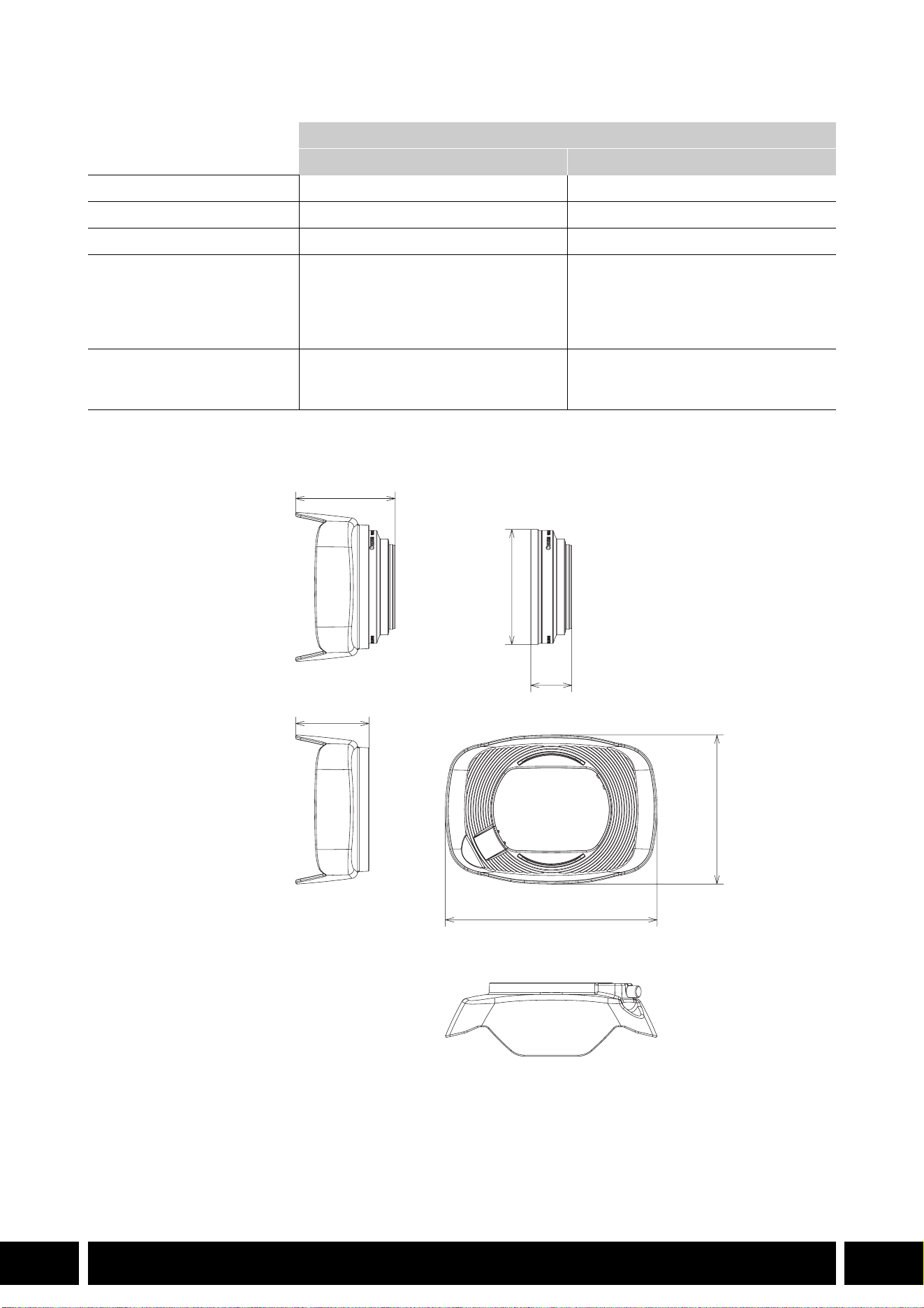
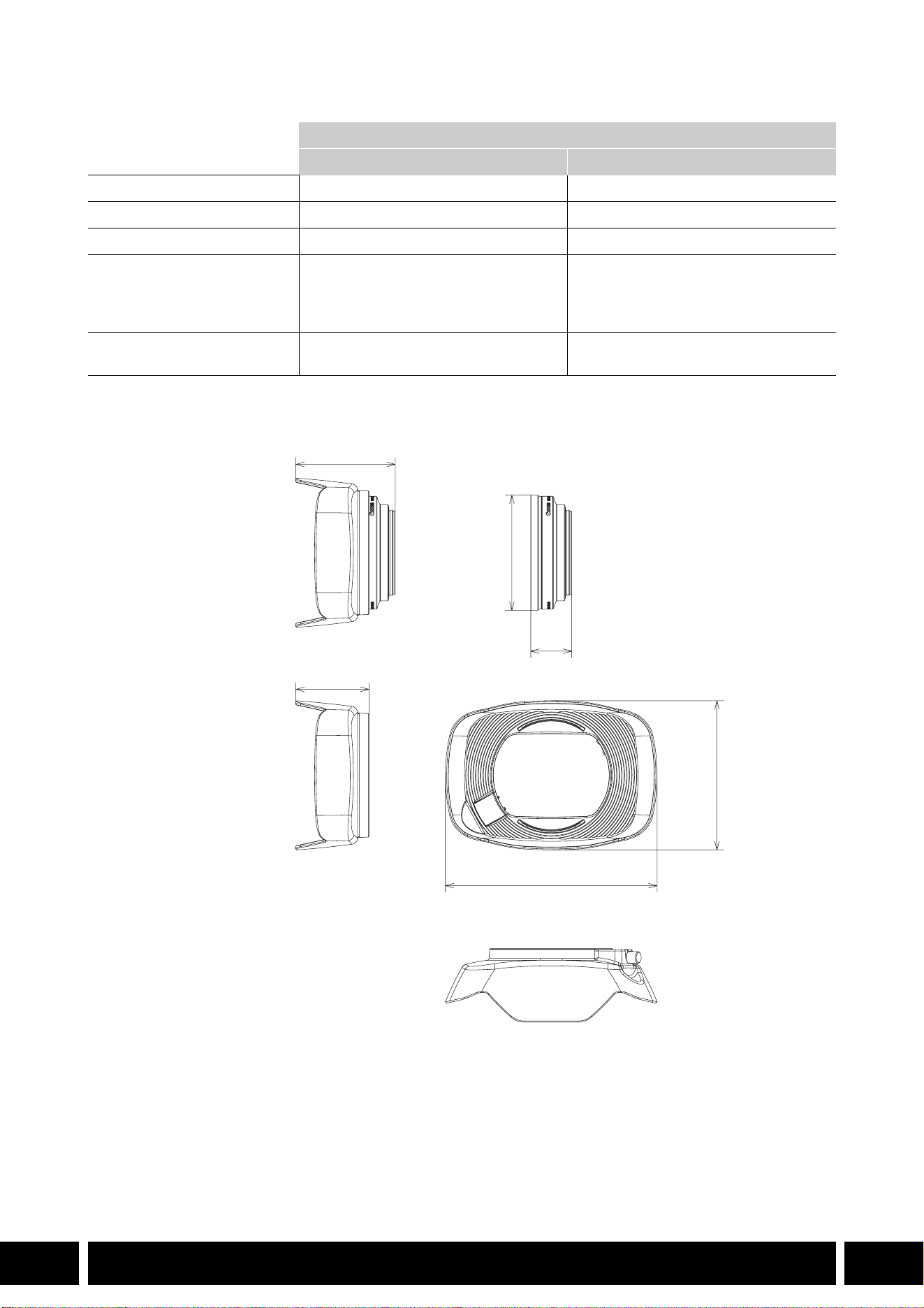
BWA-H58 寸法図
ワイドアタッチメント
WA-H58 WA-U58
倍率 約 0.75 倍約0.8 倍
レンズ構成
2群 2 枚 2群 2 枚
ねじ径
58 mm 58 mm
大きさ フードなし:
約 ∅
79 mm(最大径)×28 mm
フード付き:
約
144 mm(幅)×102 mm(高さ)
×68 mm(奥行き)
フードなし:
約 ∅ 85 mm(最大径)×33 mm
フード付き:
約
150 mm(幅)×106 mm(高さ)
×72 mm(奥行き)
質量 フードなし:約
260 g
フード付き:約 310 g
フードなし:約 325 g
フード付き:約 380 g
∅ 79
68
28
144
102
単位:mm
50
撮影スタイル/構成
12
JP
撮影スタイル/構成
ハンドルユニット HDU-1 / HDU-3
ハンドルユニット HDU-1 / HDU-3 は、カメラに取り付けると、INPUT 端子や赤外ライト、タリーランプが
使用できます。ハンドルユニットの取り付けや使いかたの詳細については、お使いのカメラの使用説明書を
ご覧ください。
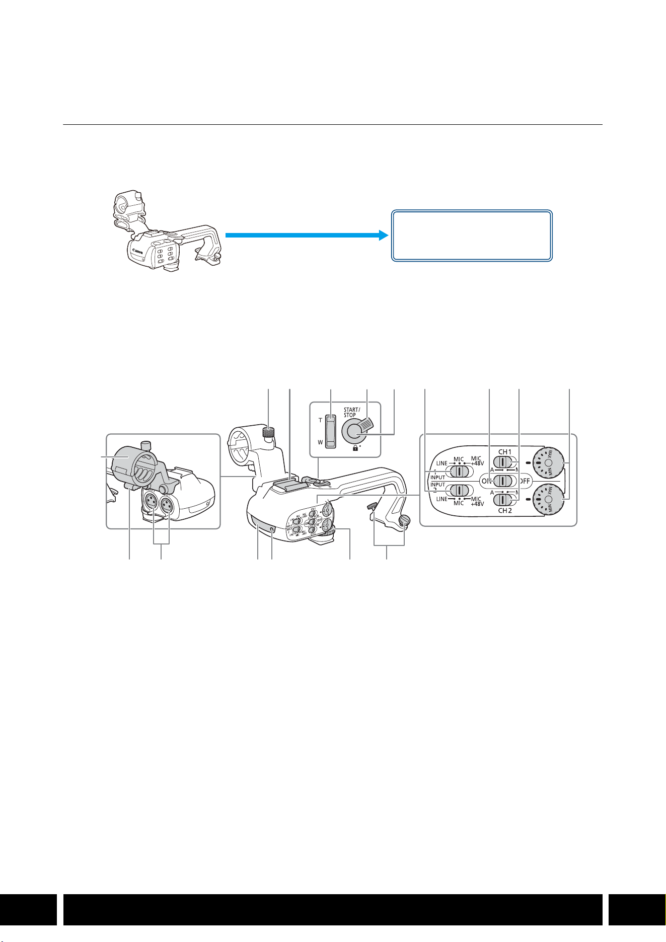
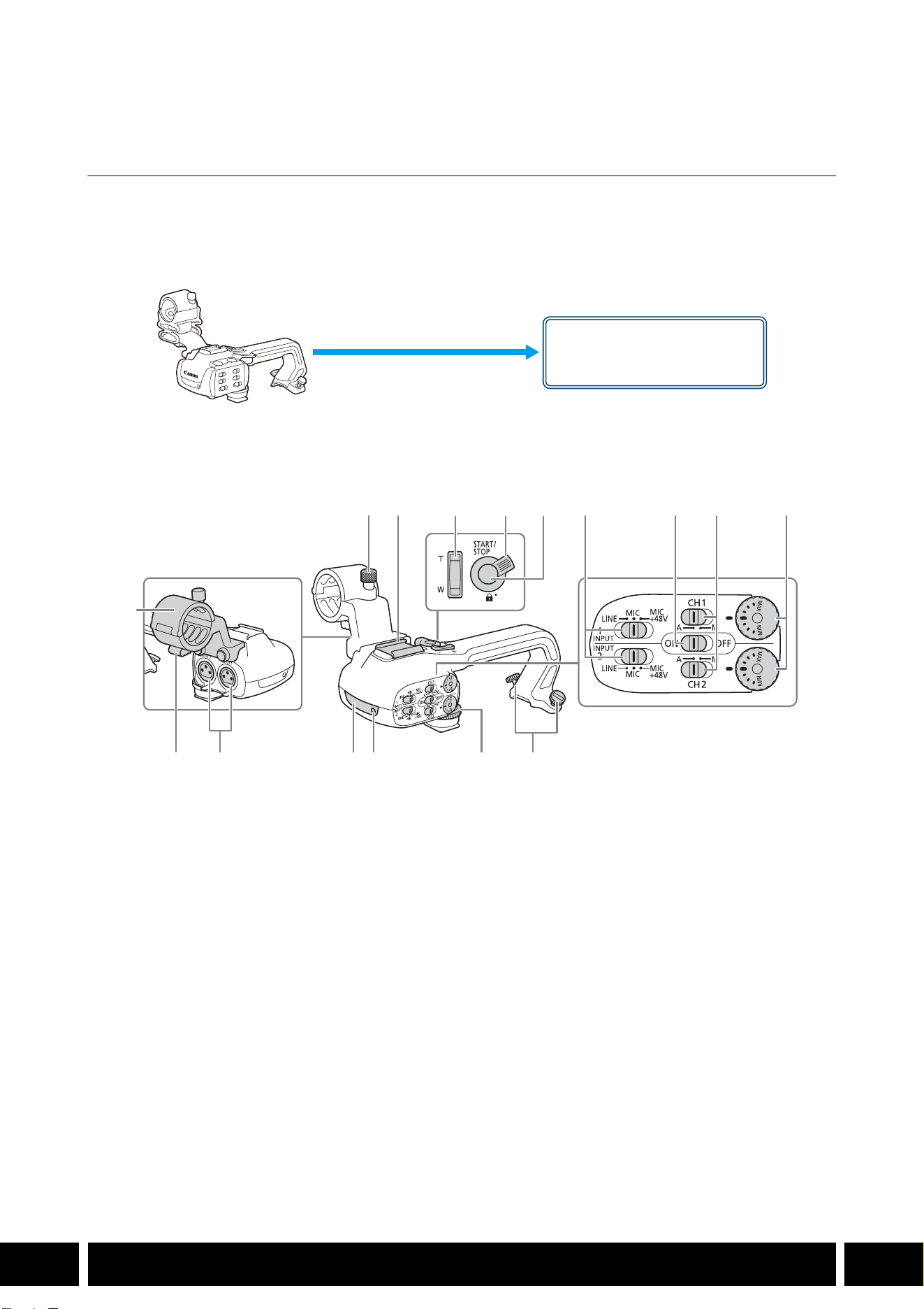
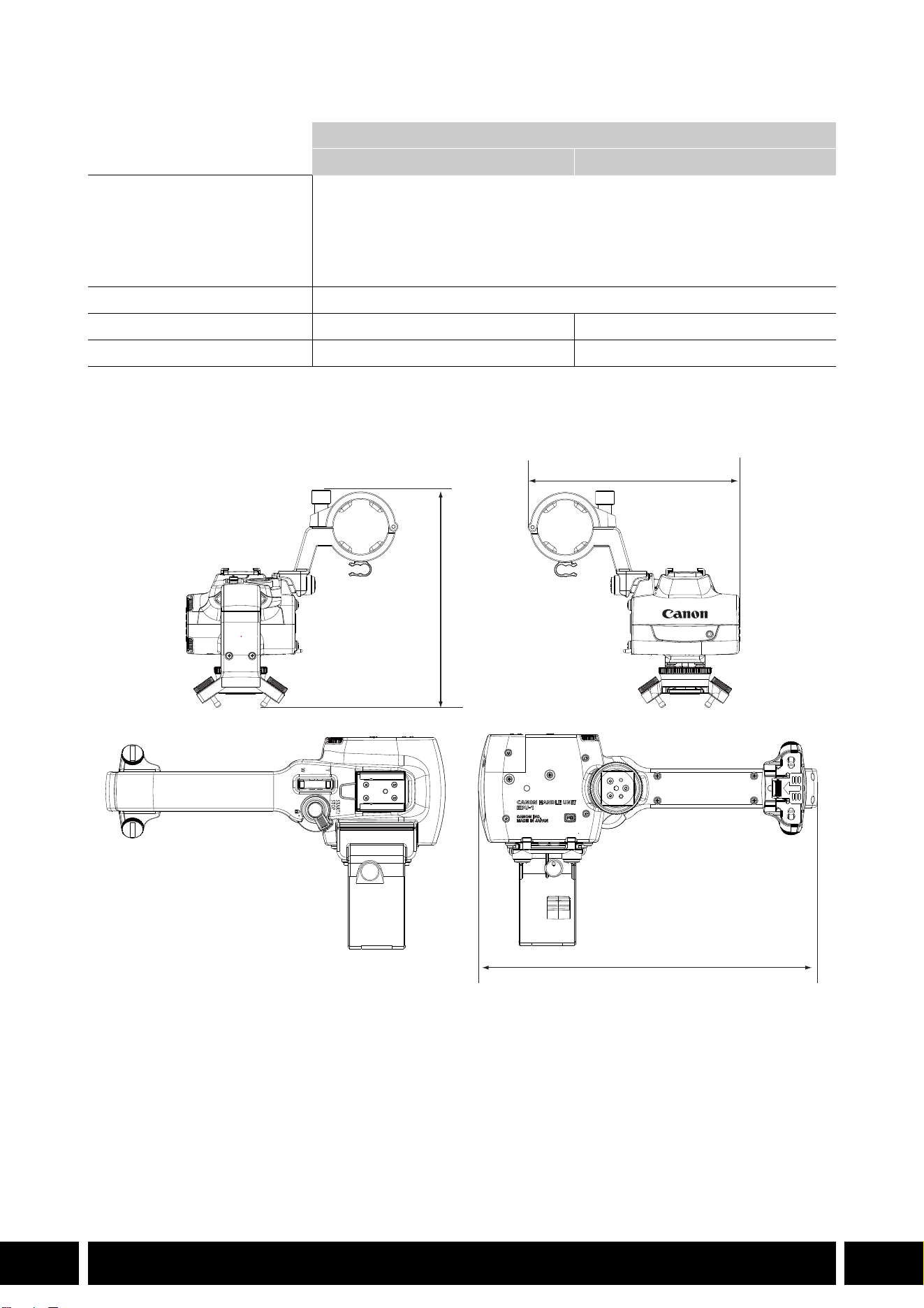
各部の名称
BHDU-1
1 外部マイク固定ネジ
2 アクセサリーシュー
3 ハンドルズームレバー
4 ロックレバー
5 START/STOP(スタート/ストップ)ボタン
6INPUT端子感度切り換えスイッチ(INPUT 1/
INPUT 2
)
7INPUT端子入力切り換えスイッチ
8 録音レベル切り換えスイッチ(CH1/CH2)
9 録音レベル調整つまみ(CH1/CH2)
10 ハンドルユニット取り付けネジ
11 ハンドルユニット固定ネジ
12 タリーランプ
13 赤外ライト
14 INPUT 1 / INPUT 2 端子
15 ケーブルクランプ
16 外部マイクホルダー
ハンドルユニット取り付け部
(直接取り付ける)
12 6 7 8 9
101112131415
16
345
撮影スタイル/構成
13
JP
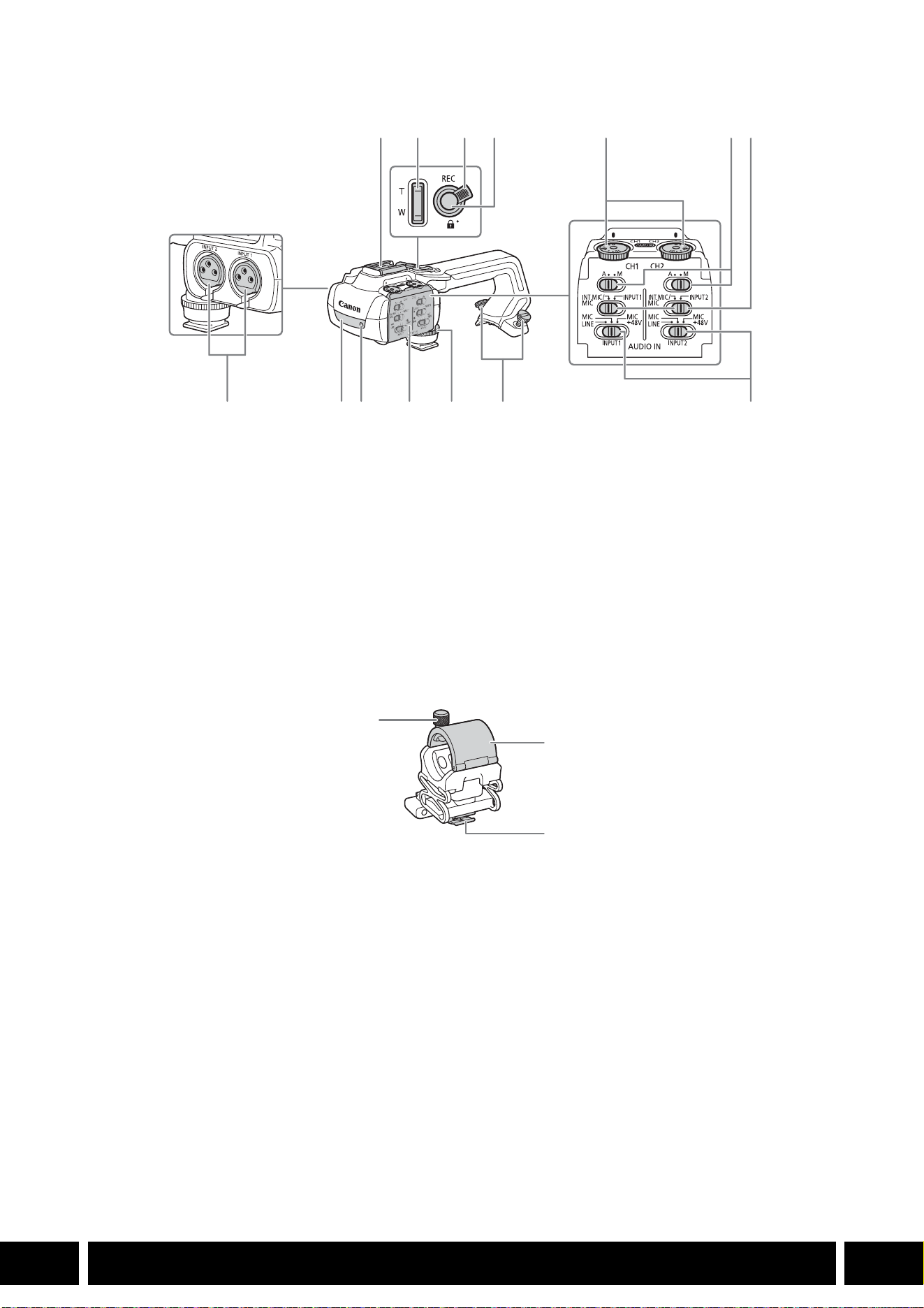
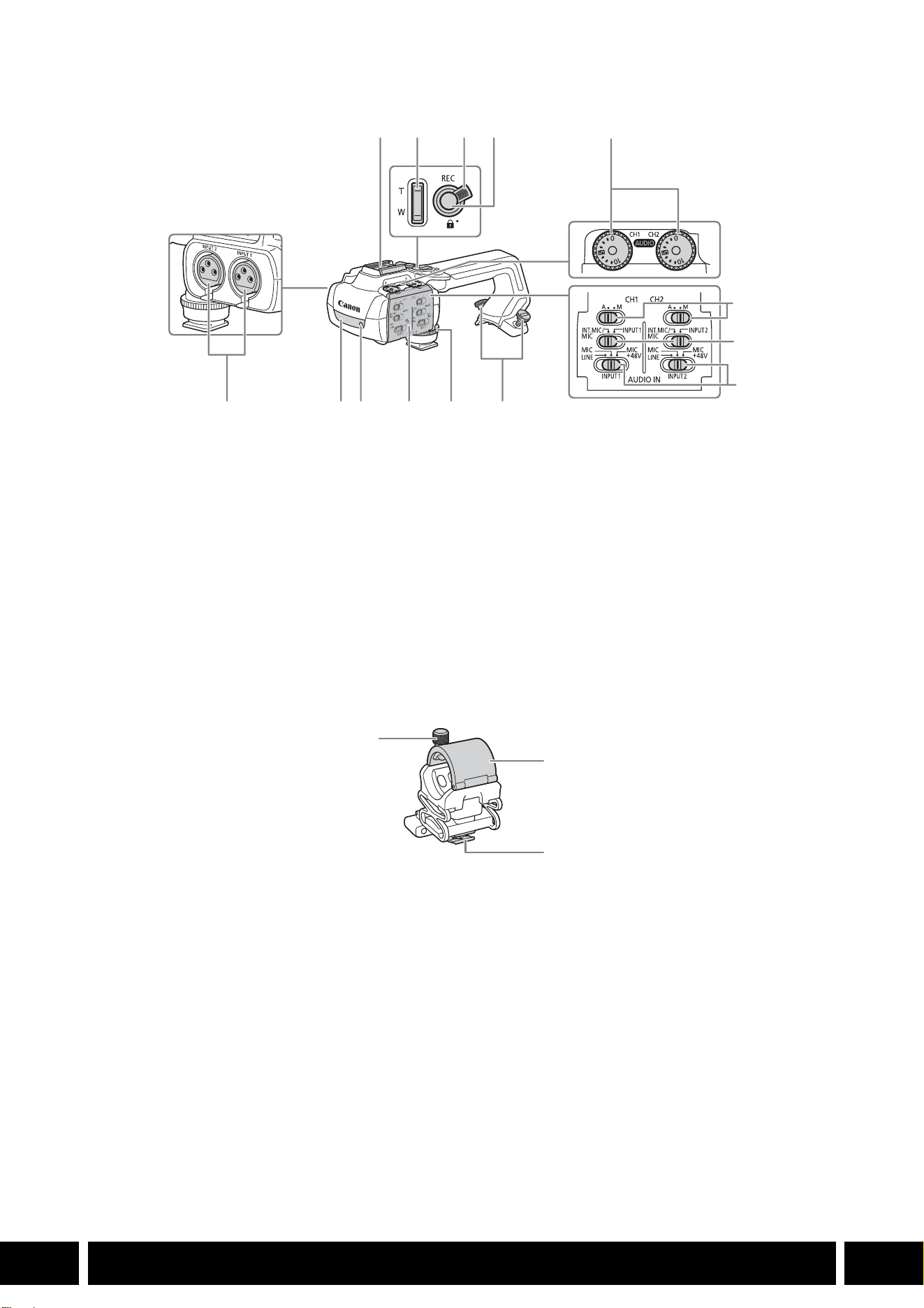
BHDU-3
マイクホルダー(HDU-3 に付属)
1 コールドシュー
バッテリービデオライト(別売)などを取り
付けます。
2 ハンドルズーム
3 ロックレバー
4 REC(記録開始/停止)ボタン
5 録音レベル調整つまみ(CH1/CH2)
6 録音レベル切り換えスイッチ(CH1/CH2)
7 AUDIO IN 切り換えスイッチ(CH1/CH2)
8 INPUT 1 / INPUT 2端子
9 赤外ライト
10 タリーランプ
11 オーディオカバー
12 ハンドルユニット固定ネジ
13 ハンドルユニット取り付けネジ
14 INPUT 1 / INPUT 2 端子切り換えスイッチ
1 外部マイク固定ネジ
2 外部マイクホルダー
3 ケーブルクランプ
17
8 9 10 11 12 13 14
234 5 6
1
2
3
撮影スタイル/構成
14
JP
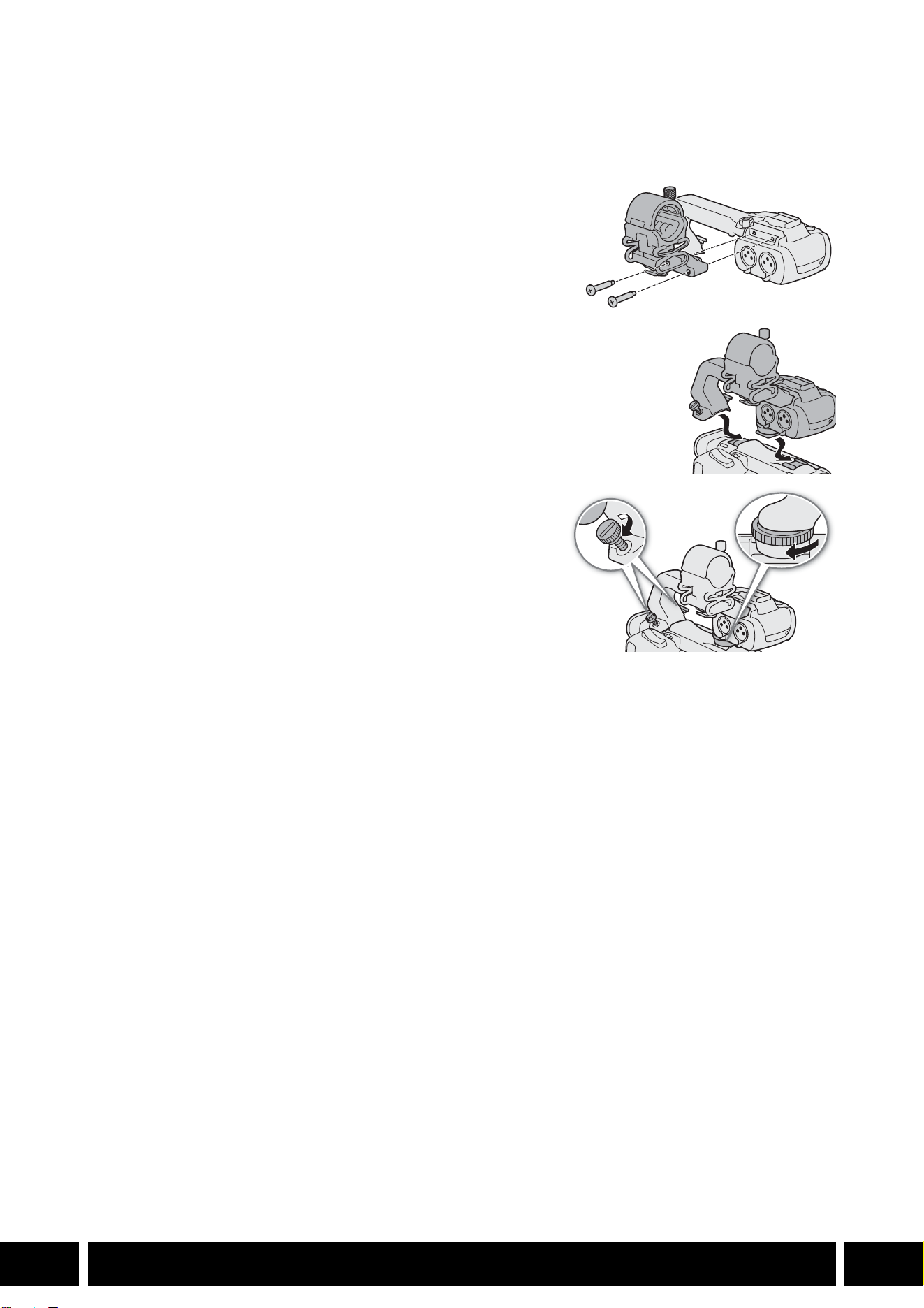
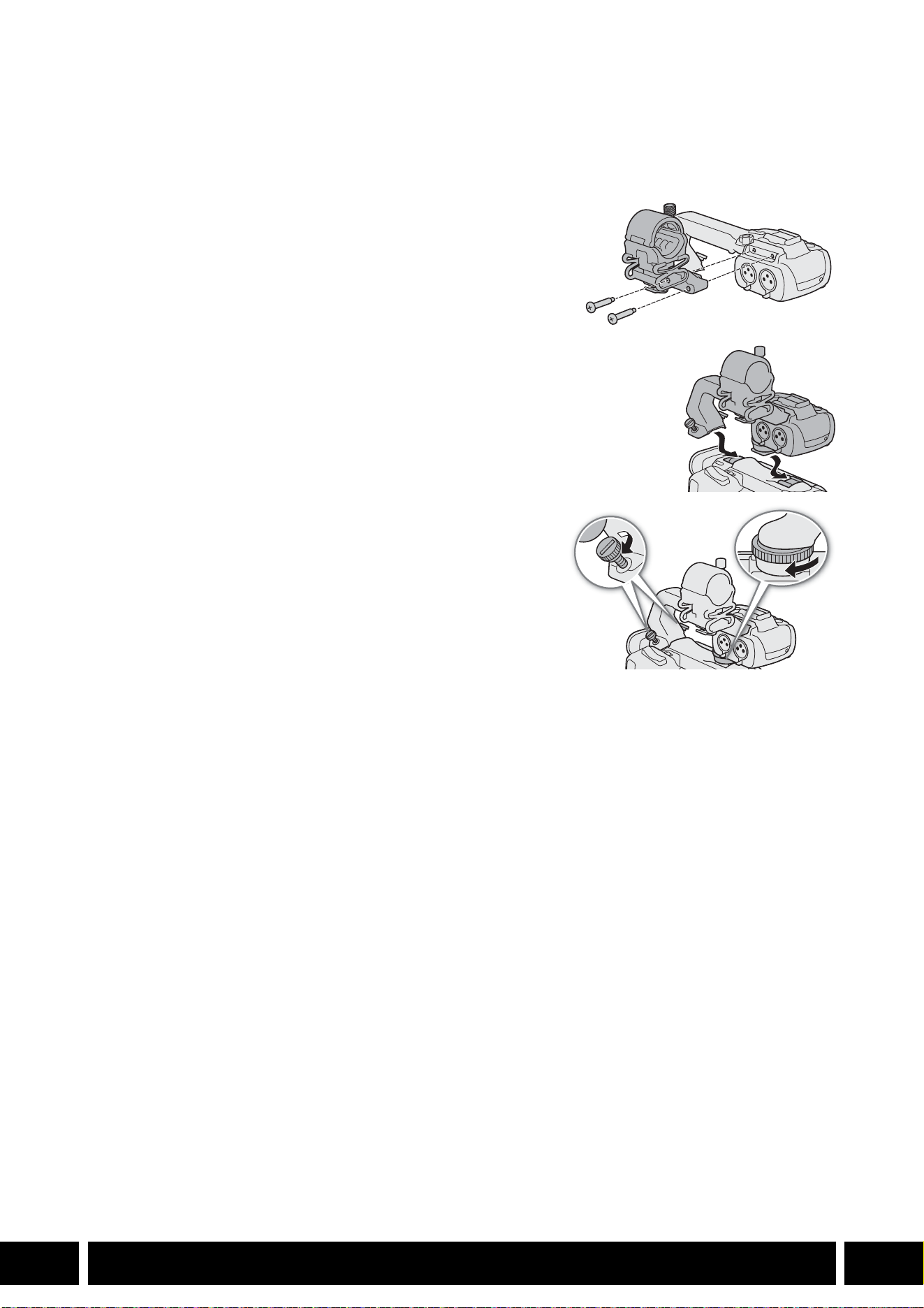
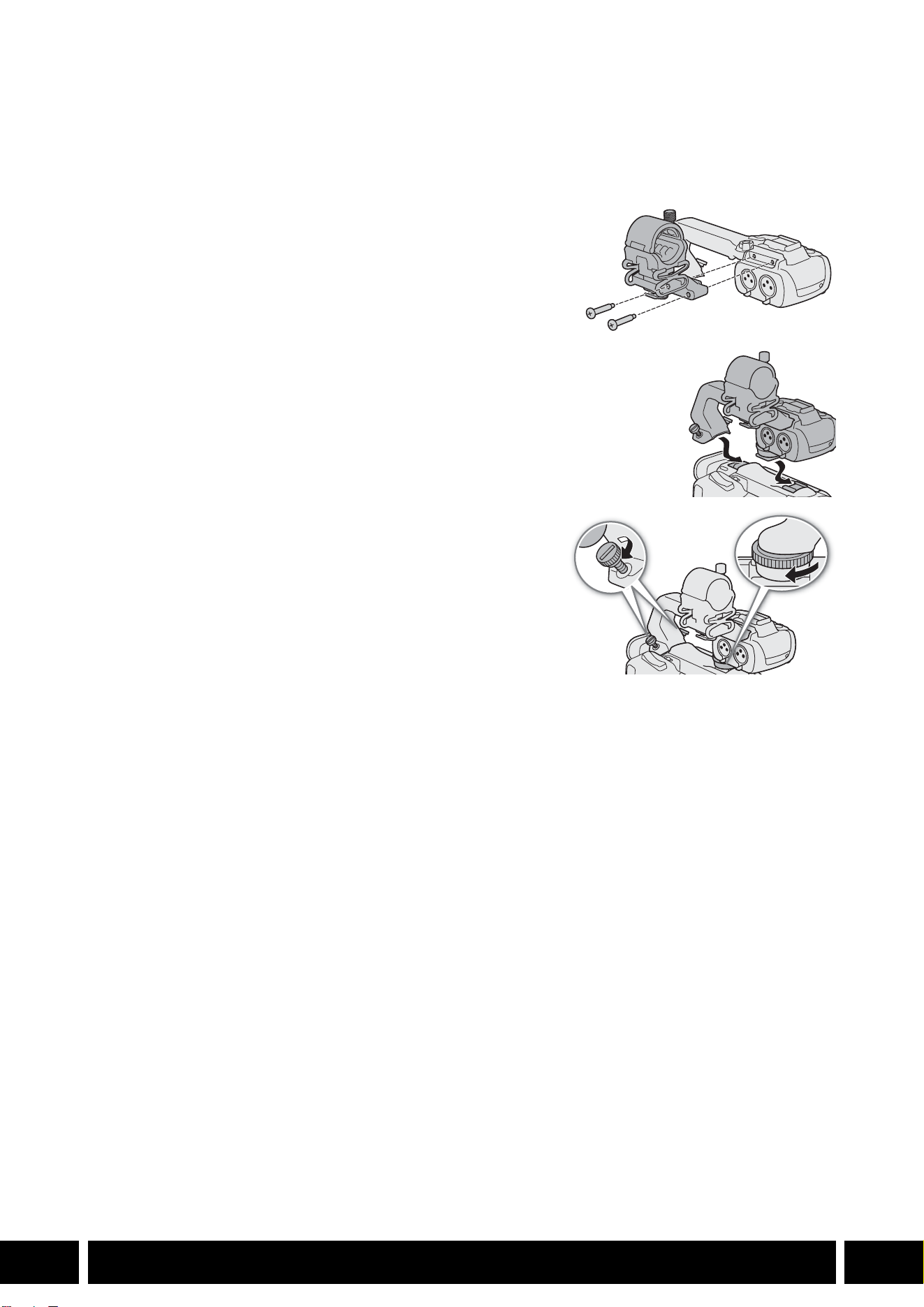
ハンドルユニットを取り付ける
カメラにハンドルユニットを取り付けます。ここでは、HDU-3 の取り付けかたを例にして説明します。
HDU-1の取り付けかたも同様です。
1. カメラの電源を切る
2. +のドライバー(市販)を使用して、ハンドルユニットに付
属の
2本のネジでマイクホルダーをハンドルユニットに取り
付ける(햲)
3. ハンドルユニットを後ろから前へスライドさせ、ハンドルユ
ニット固定ネジ差し込み部(햳)に合わせる。次にハンドル
ユニット取り付け部(햴)に合わせる
4. それぞれのネジを回してしっかり固定する(햵)
ハンドルユニット取り付けネジは、コインなどでしっかり
締めてください。
햲
햳
햴
햵
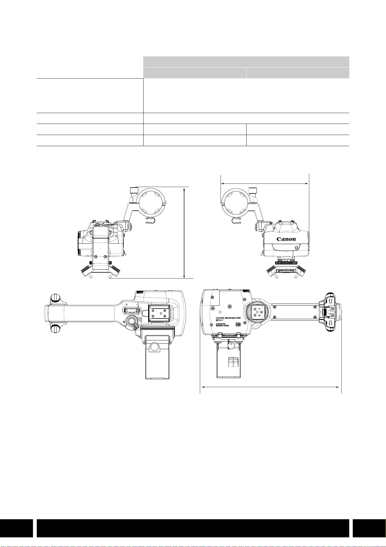
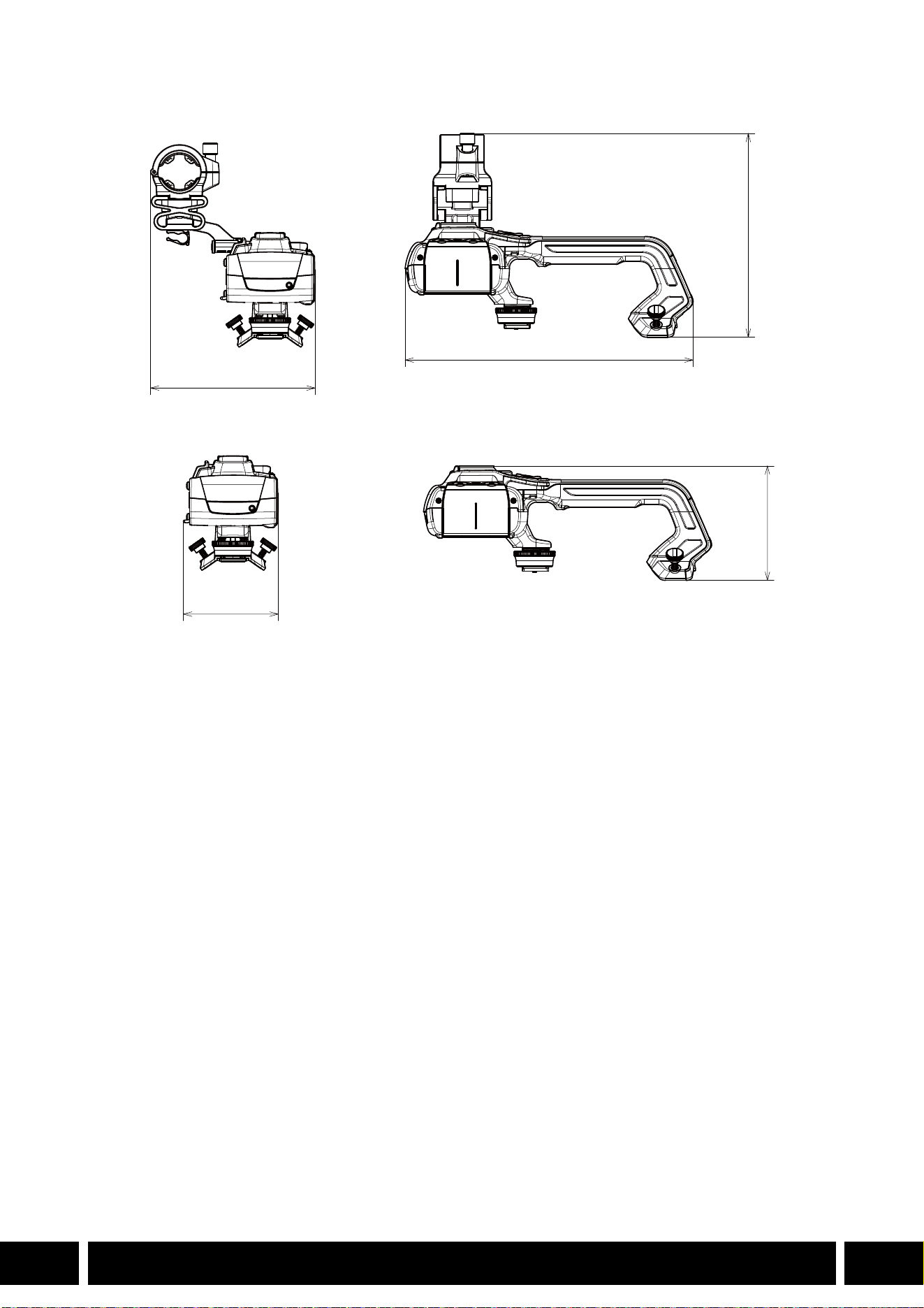

TABLE OF CONTENTS
2
EN
3Introduction
4 Accessories and Compatible Cameras Mentioned in this User Guide
5 Communications
5 GP-E2 GPS Receiver
7 Added Functionality and Lens Compatibility
7 TL-H58 / TL-U58 Tele-converter
9 WA-H58 / WA-U58 Wide Attachment
12 Shooting Styles and Configuration
12 HDU-1 / HDU-3 Handle Unit
Table of Contents
INTRODUCTION
3
EN
Introduction
This user guide covers optional accessories compatible with Canon cameras. It provides information about
how to use the accessories, their compatibility and specifications. Be sure to read this information in
addition to the supplied instruction manuals to use the products correctly.
Before Using the Accessories
•Unless specified otherwise, power to the accessories is supplied by the camera.
•Your camera may not support all the camera features and functions described in this guide. Refer also to
the instruction manual of the camera being used.
•Some of the accessories and tools mentioned in this guide may be supplied with some camera models.
Check the list of supplied accessories in the instruction manual of the camera being used.
If an accessory/tool is not supplied with the camera or with the product being explained, please use an
optional accessory or commercially available product.
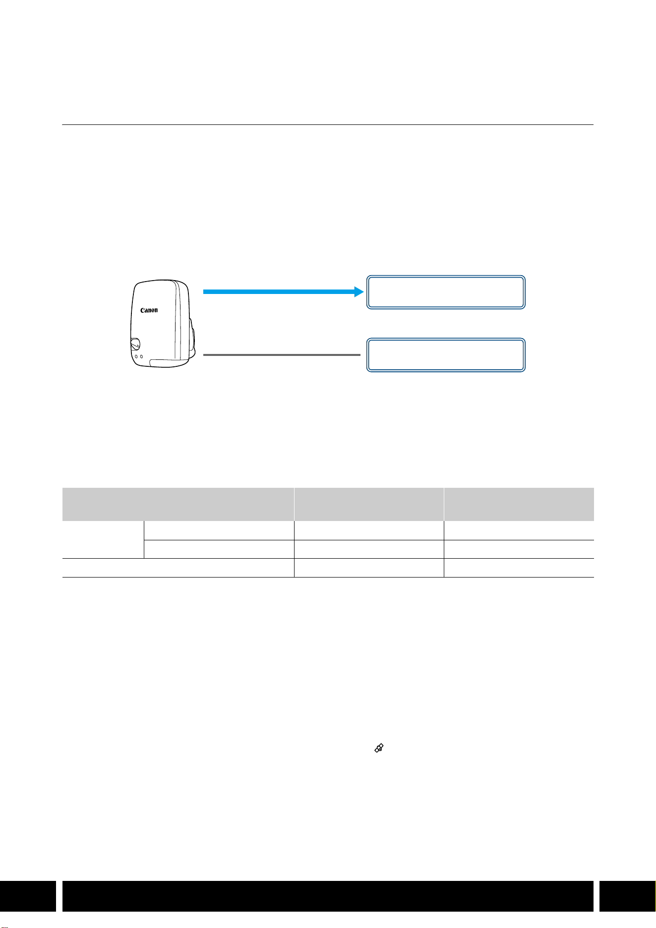
Conventions in this Document
• Important precautions related to the product’s operation.
• Additional information that complements the basic operation procedures.
•0 Reference page number in this document.
•“Camera” refers to a compatible Canon camera or camcorder (0 4).
•This is a multilingual document. You can click on the language code on any page to return
to the beginning of the guide (Table of Contents) in that language.
•Be careful not to drop the camera or accessories when attaching, removing or adjusting the
various accessories. Use a table or other stable surface.
•Do not connect/attach accessories to cameras and devices that are not compatible with them.
EN
The information in this document is verified as of January 2024. Subject to change without previous
notice.

ACCESSORIES AND COMPATIBLE CAMERAS MENTIONED IN THIS USER GUIDE
4
EN
Accessories and Compatible Cameras
Mentioned in this User Guide
The following table lists the main accessories that extend the camera's functionality.
1
For details see the instruction manual of the camera and the accessory in use.
2
This is a class A product. In a domestic environment this product may cause radio interference in which case the
user may be required to take adequate measures.
Accessory XF705 XF605
XA75 /
XA70
XA65 /
XA60
XA55 /
XA50
XA45 /
XA40
0
Communications
GP-E2 GPS Receiver NNNNNN5
Added Functionality and Lens Compatibility
RC-V100 Remote Controller NNNNNN—
1
RC-IP100 / RC-IP1000 Remote Camera
Controller
2
N —
1
WL-D89 Wireless Controller N —
1
WL-D6000 Wireless Controller N —
1
TL-H58 / TL-U58 Tele-converter TL-U58 TL-U58 TL-U58 TL-H58 TL-U58 TL-H58 7
WA-H58 / WA-U58 Wide Attachment WA-U58 WA-U58 WA-U58 WA-H58 WA-U58 WA-H58 9
Shooting Styles and Configuration
HDU-1 / HDU-3 Handle Unit HDU-3 HDU-1 12
COMMUNICATIONS
5
EN
Communications
GP-E2 GPS Receiver
Connect the GPS receiver to the camera’s multi-function shoe or USB terminal in CAMERA (shooting)
mode to have the GPS information (latitude, longitude, altitude) recorded with the metadata of clips and
photos. If you connect the receiver to the camera’s USB terminal, while recording, it is recommended to
place the receiver in the supplied carrying case and attach it to the camera’s grip belt or carry it on your
person. An AA battery is required to use the GP-E2.
For details about attaching and configuring the receiver, refer to the GP-E2’s instruction manual.
When using a camera with a Type-C USB terminal, an IFC-40AB III or IFC-150AB III Interface Cable (sold
separately) is required. Depending on the camera, it may be necessary to adjust the USB terminal settings.
For details, refer to the instruction manual of the camera being used.
Recorded Information
* You can use the GPS information to search and organize clips using Canon XF Utility.
Connecting and Activating the GPS Receiver
1. Turn off the receiver.
2. Connect the receiver to the camera.
•Use the camera’s multi-function shoe, the USB cable supplied with the GP-E2 or an optional
interface cable.
3. Turn on the receiver.
•The GPS function is activated. The icon appears on the screen and will flash as the receiver tries
to acquire satellite signals.
•When satellite signals are correctly acquired, the icon will stay continuously on. Clips and photos
recorded after that will be geotagged.
Recording format
GPS information
(latitude, longitude, altitude)
Coordinated universal time
(UTC)
Clips
MP4 NN
XF-AVC* N —
Photos NN
USB cable
(supplied with the GP-E2)
USB terminal
(attach directly)
or
Multi-function shoe

COMMUNICATIONS
6
EN
•Do not connect the GP-E2 to the camera’s multi-function shoe and the USB terminal at the
same time.
•In certain countries/regions, the use of GPS may be restricted. Be sure to use the GPS receiver
in accordance with local laws and regulations of the country/region where the receiver is used.
Be particularly careful when traveling outside of your home country.
•Be careful about using GPS functions where the operation of electronic devices is restricted.
•The GPS information recorded with clips and photos may contain data that can lead others to
locate or identify you. Be careful when sharing geotagged recordings with others or when
uploading them to the Web.
•Do not leave the receiver near strong electromagnetic fields such as near powerful magnets
and motors.
•The GPS information recorded with clips corresponds to the location at the start of the
recording.
•You can have the camera’s date and time settings adjusted automatically according to the
information received from the GPS signal. See the [System Setup] menu settings’ table in the
instruction manual of the camera being used.
•Initial GPS signal reception will take longer after replacing the receiver’s battery or when first
turning on the receiver after a prolonged period of having been turned off.
•Do not place cables connected to the camera’s terminals near the receiver. Doing so may
negatively affect the GPS signal.
•Cameras with status screens only: You can check the GPS information being received and the
satellite’s signal strength on the status screens. For details see the instruction manual of the
camera being used.
•The camera is not compatible with the following receiver functions.
–The [Set now] option for the automatic date adjustment function
–Digital compass function
–Positioning interval function
ADDED FUNCTIONALITY AND LENS COMPATIBILITY
7
EN
Added Functionality and Lens Compatibility
TL-H58 / TL-U58 Tele-converter
Using the TL-H58/TL-U58 Tele-converter with a Canon camera increases the focal length of the camera
lens by a factor of approximately 1.5. Depending on the camera, the image stabilization method and the
minimum object distance may change. For details about the various functions, refer to the instruction
manual of the camera being used.
Attaching a Tele-converter to the Camera
This section explains how to attach a tele-converter to the camera, using the TL-U58 as an example. You
can attach the TL-H58 following the same steps.
Screw the Tele-converter fully into the lens filter thread.
Supplied Accessories
Soft case
Lens cap
Dust cap
•Do not point the lens at the sun when the tele-converter is attached to the camera. This may
damage the camera.
•Other filters and the camera’s lens hood cannot be used together with the tele-converter.
•Use a tripod to prevent motion blur.
•Clean the surfaces of the tele-converter and the camera’s lens before use. Otherwise, the
camera may focus incorrectly on dust particles or other matter on the lens surfaces.
•Using the tele-converter may obstruct the front tally lamp*, reduce the effective range of the
wireless controller or cause a shadow to appear when recording using an optional video light*.
* Not all camera models feature a tally lamp or are compatible with optional video lights.
•When recording at full wide-angle (W) with the tele-converter attached, depending on the
camera model, the frame of the lens may appear around the outer edge of the picture.
•Take care when handling the tele-converter, to avoid smudging and fingerprints.
•Do not store the tele-converter in a humid place. It may mold.
•We recommend you attach the tele-converter to the camera before adjusting the white balance.

ADDED FUNCTIONALITY AND LENS COMPATIBILITY
8
EN
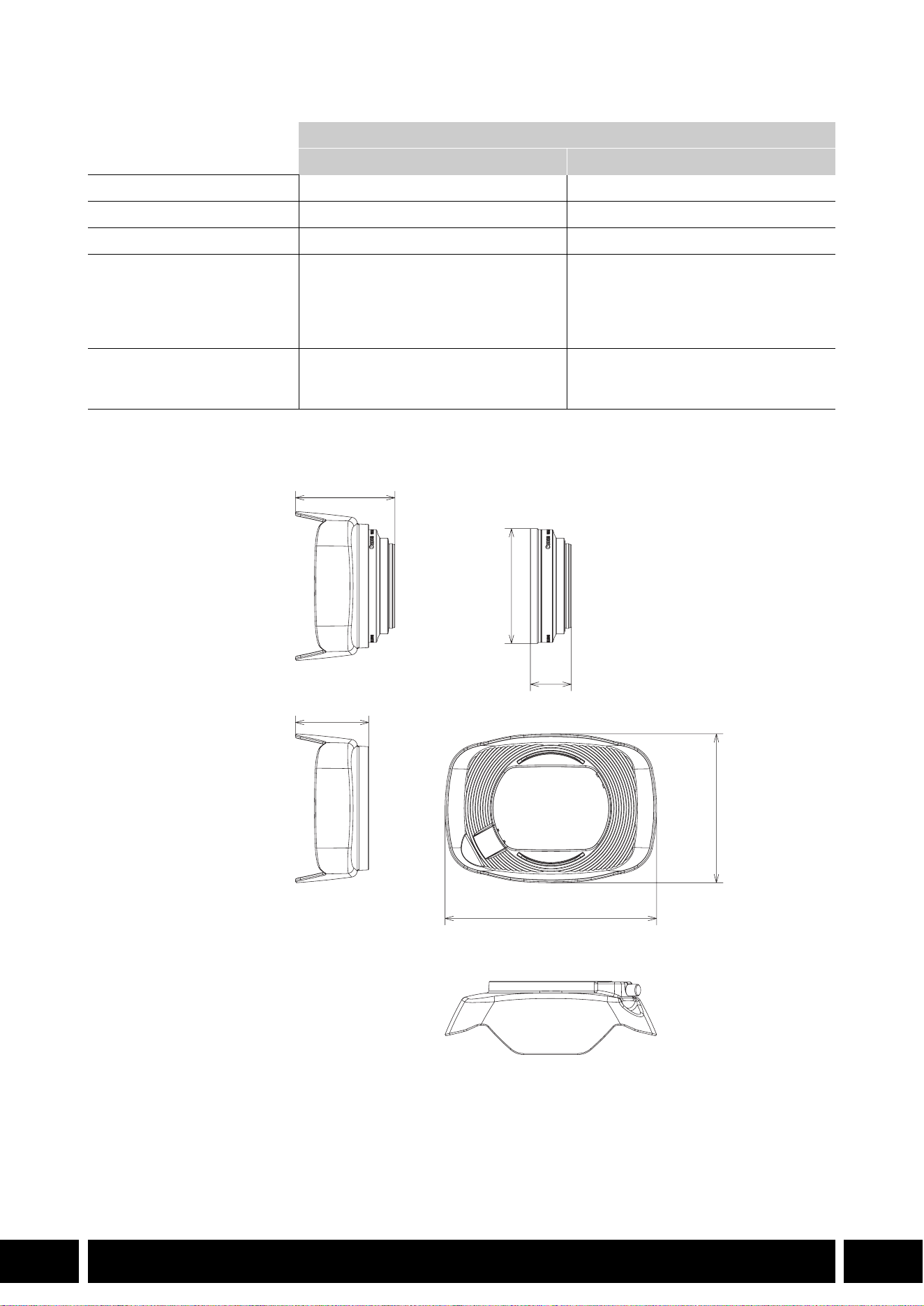
Specifications
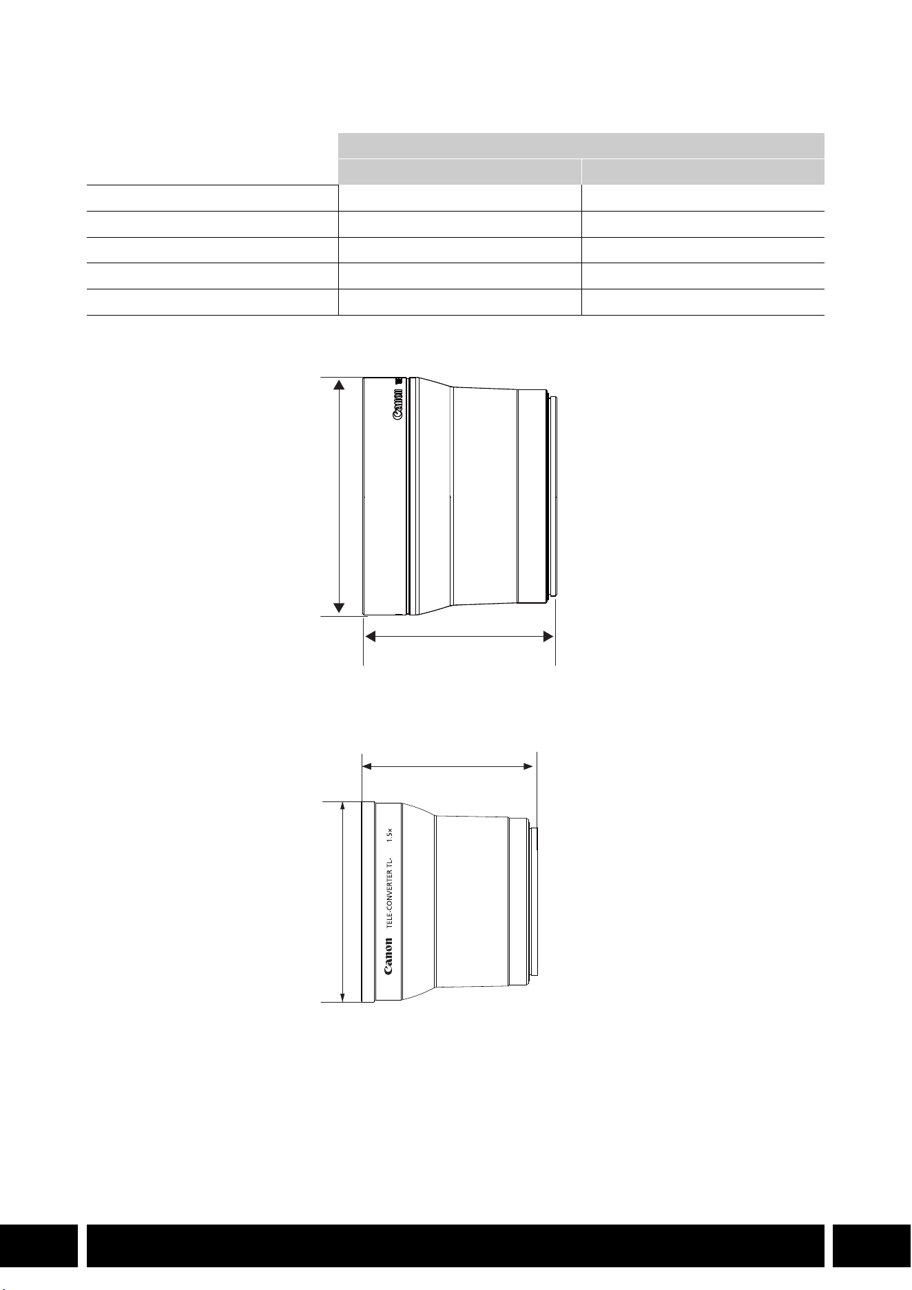
TL-H58 Detailed Measurements
TL-U58 Detailed Measurements
Tele-converter
TL-H58 TL-U58
Magnification 1.5× 1.5×
Lens construction 5 elements in 3 groups 5 elements in 3 groups
Filter diameter 58 mm 58 mm
Dimensions ∅ 69 × 64 mm (length) (2.7 × 2.5 in.) ∅ 79 × 69 mm (length) (3.1 × 2.7 in.)
Weight Approx. 273 g (9.6 oz.) Approx. 350 g (12.3 oz.)
mm (inches)
ø 69 (2.7)
64 (2.5)
U58
mm (inches)
ø 79 (3.1)
69 (2.7)

ADDED FUNCTIONALITY AND LENS COMPATIBILITY
9
EN
WA-H58 / WA-U58 Wide Attachment
The WA-H58/WA-U58 Wide Attachment allows you to record movies and take photos covering a wider
angle of view. Depending on the camera, the image stabilization method and the minimum object distance
may change. For details about the various functions, refer to the instruction manual of the camera being
used.
Attaching a Wide Attachment to the Camera
This section explains how to attach a wide attachment to the camera, using the WA-U58 as an example.
You can attach the WA-H58 following the same steps.
1. Remove the lens hood supplied with the camera and screw
the wide attachment fully into the lens filter thread (햲).
2. Attach the hood supplied with the wide attachment to the front
of the wide attachment and tighten the locking screw (햳).
•Attach the hood straight, paying attention not to warp it. If the
hood is bent out of shape, its shadow may appear in the picture.
Supplied Accessories
Soft case
Lens cap
Dust cap
Hood
•Using the wide attachment, the outer periphery of the image may appear warped.
•Other filters and the camera’s lens hood cannot be used together with the wide attachment.
•Clean the surfaces of the wide attachment and the camera’s lens before use. Otherwise, the
camera may focus incorrectly on dust particles or other matter on the lens surfaces.
•Using the wide attachment may obstruct the front tally lamp*, reduce the effective range of the
wireless controller or cause a shadow to appear when recording using an optional video light*.
* Not all camera models feature a tally lamp or are compatible with optional video lights.
•Take care when handling the wide attachment to avoid smudging and fingerprints.
•Make sure to attach the lens cap when storing the wide attachment.
•Do not store the wide attachment in a humid place. It may mold.
•When adjusting the white balance, it is recommended to attach the wide attachment to the
camera first and then adjust the white balance.
햲
햳
ADDED FUNCTIONALITY AND LENS COMPATIBILITY
10
EN
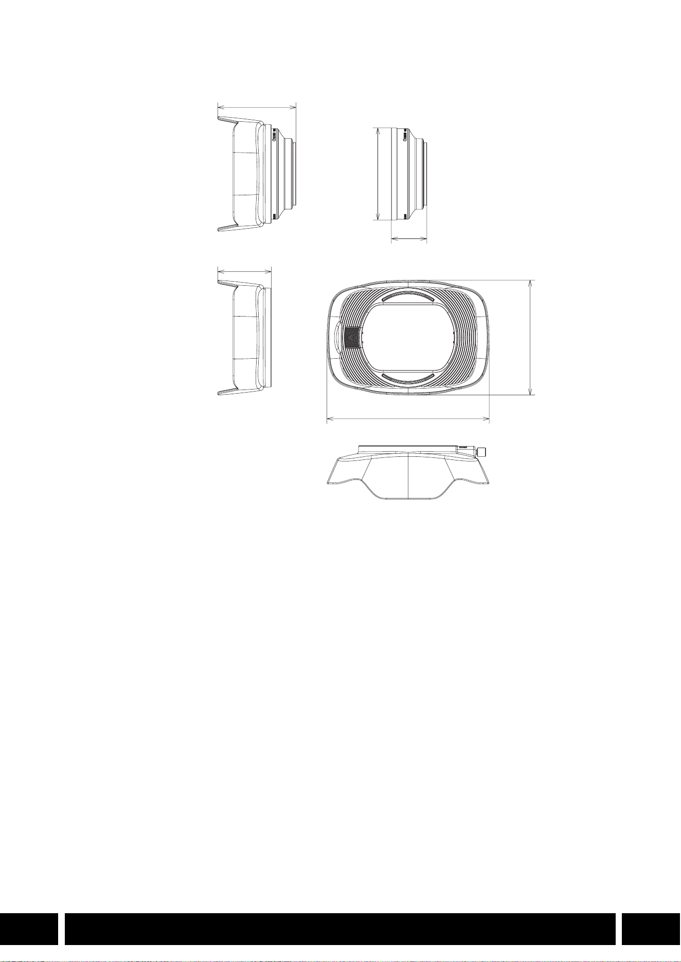
Specifications
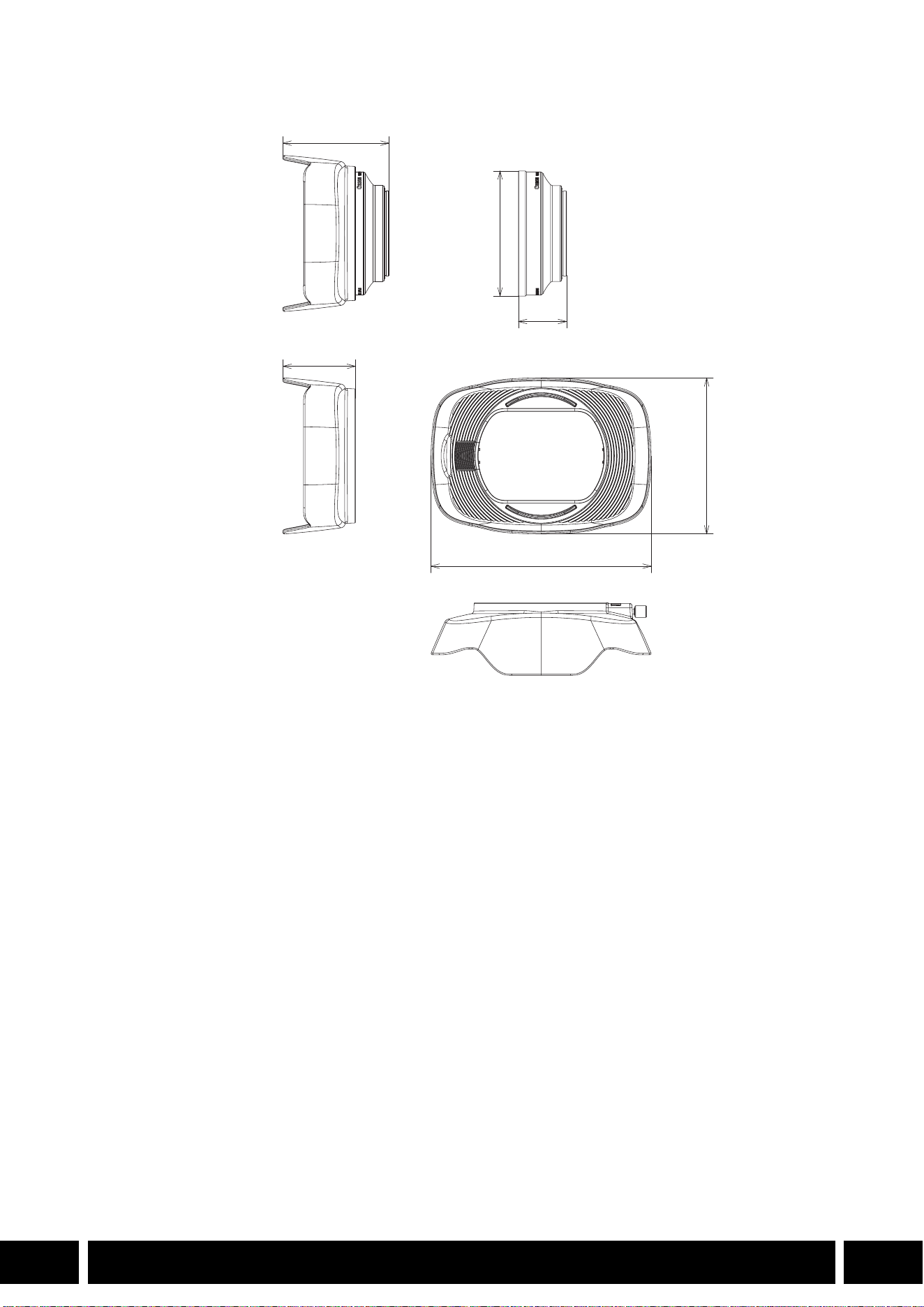
WA-H58 Detailed Measurements
Wide Attachment
WA-H58 WA-U58
Magnification Approx. 0.75× Approx. 0.8×
Lens construction 2 elements in 2 groups 2 elements in 2 groups
Filter diameter 58 mm 58 mm
Dimensions ∅ 79 × 28 mm (length)
(3.1 × 1.1 in.) (without the hood)
144 × 102 × 68 mm
(W × H × D) (5.7 × 4.0 × 2.7 in.)
(with the hood attached)
∅ 85 × 33 mm (length)
(3.3 × 1.3 in.) (without the hood)
150 × 106 × 72 mm
(W × H × D) (5.9 × 4.2 × 2.8 in.)
(with the hood attached)
Weight 260 g (9.2 oz.) (without the hood)
310 g (10.9 oz.) (with the hood
attached)
325 g (11.5 oz.) (without the hood)
380 g (13.4 oz.) (with the hood
attached)
mm (inches)
ø 79 (3.1)
68 (2.7)
28 (1.1)
144 (5.7)
102 (4.0)
50 (2.0)

SHOOTING STYLES AND CONFIGURATION
12
EN
Shooting Styles and Configuration
HDU-1 / HDU-3 Handle Unit
By connecting the handle unit to the camera, you can use the INPUT terminal, the infrared light and the tally
lamp.
For details on how to attach and use the handle unit, see the instruction manual of the camera being used.
Names of Parts
HDU-1
1 Microphone holder unit
2 Microphone lock screw
3 Accessory shoe
4 Handle zoom rocker
5 START/STOP lock (C) lever
6 START/STOP button
7 Sensitivity selection switches for INPUT 1 and
INPUT 2
8 INPUT terminal ON/OFF switch
9 Audio level switches for CH1 and CH2
10 Audio level dials for CH1 and CH2
11 Microphone cable clamp
12 INPUT 1 and INPUT 2 terminals
13 Infrared light
14 Tally lamp
15 Handle unit front screw
16 Handle unit rear screws
Handle unit mount
(attach directly)
23 7 8 9 10
161514131211
1
456
SHOOTING STYLES AND CONFIGURATION
13
EN
HDU-3
Microphone Holder Unit (supplied with the HDU-3)
1 Cold shoe
2 Handle zoom rocker
3 REC button’s lock (C) lever
4 REC (start/stop recording video) button
5 Audio level dials: for CH1 (left) and CH2 (right)
6 Audio level switches: for CH1 (left) and CH2
(right)
7 AUDIO IN switches (audio input selection): for
CH1 (left) and CH2 (right)
8 INPUT 1 (left) / INPUT 2 (right) switches
(audio source selection)
9 INPUT terminals: INPUT 1 (right), INPUT 2 (left)
10 Infrared light
11 Tally lamp
12 Audio controls cover
13 Handle unit front screw
14 Handle unit rear screws
1 Microphone lock screw
2 Microphone holder
3 Microphone cable clamp
1
7
8
91011121314
234
5
6
1
2
3

SHOOTING STYLES AND CONFIGURATION
14
EN
Attaching the Handle Unit
This section explains how to attach a handle-unit to the camera, using the HDU-3 as an example. You can
attach the HDU-1 following the same steps.
1. Turn off the camera.
2. Attach the microphone holder unit to the handle unit.
•Use a commercially available Phillips head (“crosshead”)
screwdriver and the two supplied screws.
3. Align the handle unit with the handle attachment unit and
then slide the handle unit forward all the way.
4. Firmly tighten the front and rear screws.
•To tighten the rear screws you can use a coin or similar
object.

SHOOTING STYLES AND CONFIGURATION
15
EN
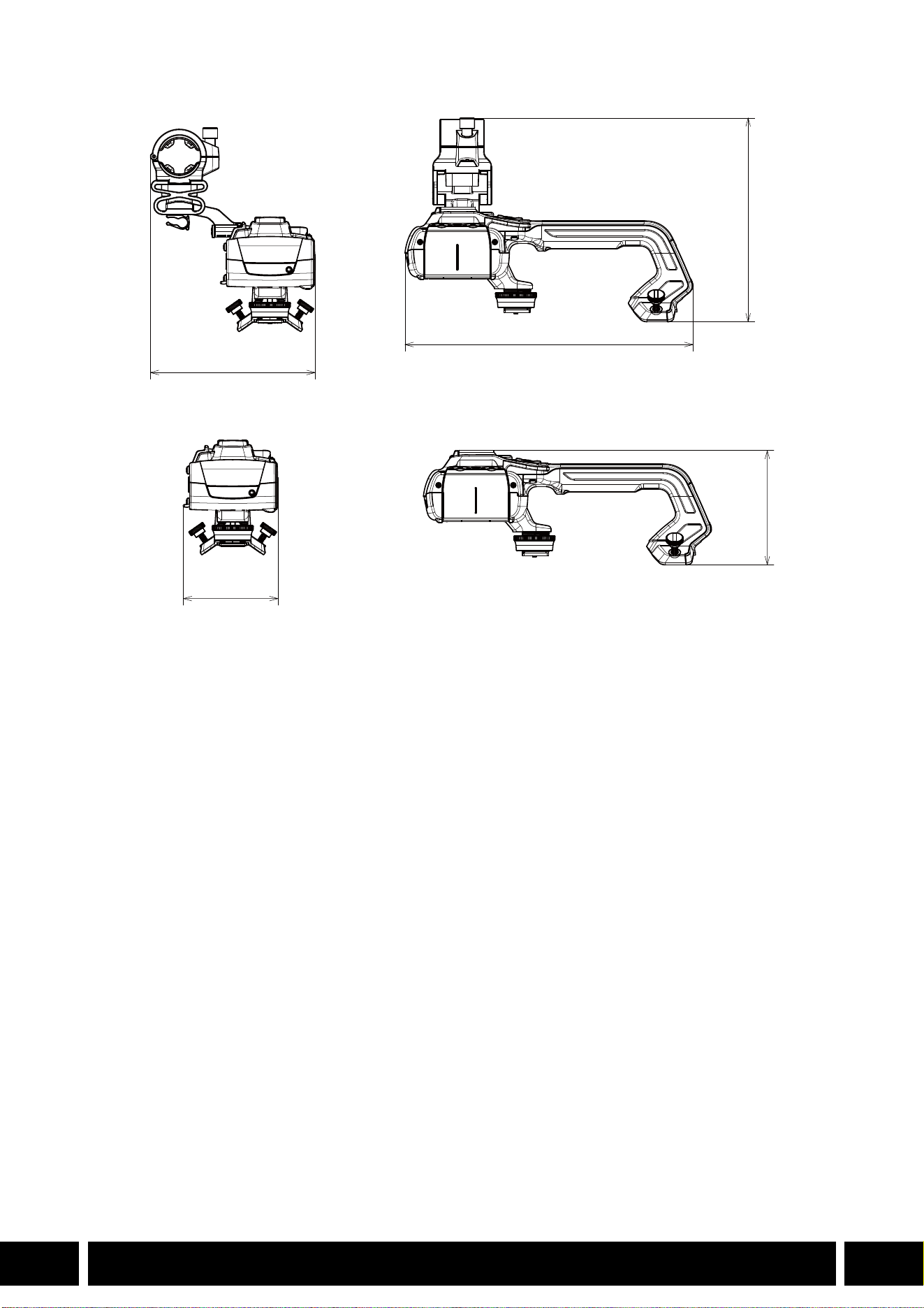
Specifications
* All dimensions and weights are approximate.
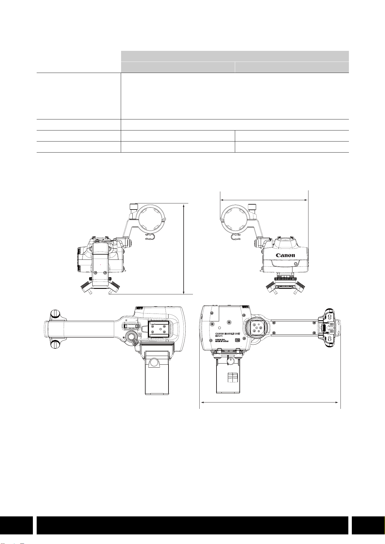
HDU-1 Detailed Measurements
Handle Unit
HDU-1 HDU-3
INPUT 1, INPUT 2 terminals XLR 3-pin jack (pin1: shield, pin2: hot, pin3: cold), 2 sets (balanced)
Sensitivity:
MIC setting: –60 dBu (volume center, full scale –18 dB)
LINE setting: 4 dBu (volume center, full scale –18 dB)
Attenuator: 20 dB
Operating temperature 0 °C – 40 °C (32 °F – 104 °F)
Dimensions* (W × H × D) 112 × 115 × 180 mm
(4.4 × 4.5 × 7.1 in.)
112 × 139 × 197 mm
(4.4 × 5.5 × 7.8 in.)
Weight* 253 g (8.9 oz.) 305 g (10.7 oz.)
mm (inches)
115 (4.5)
112 (4.4)
180 (7.1)
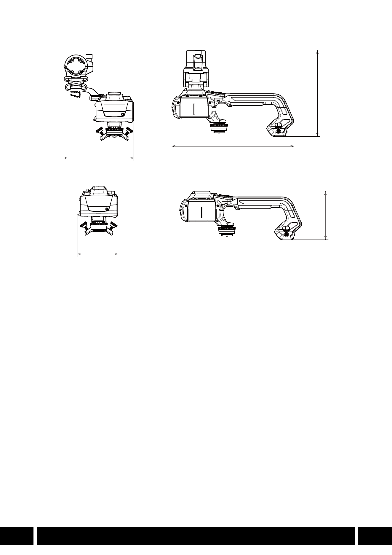

TABLE DES MATIÈRES
2
FR
3Introduction
4 Accessoires et caméras compatibles mentionnés dans ce guide d’utilisation
5 Communications
5 Récepteur GPS GP-E2
7 Fonctionnalité supplémentaire et compatibilité avec l’objectif
7 Convertisseur télé TL-H58 / TL-U58
9 Complément grand-angle WA-H58 / WA-U58
12 Styles de prise de vue et configuration
12 Poignée HDU-1 / HDU-3
Table des matières
INTRODUCTION
3
FR
Introduction
Ce guide d’utilisation couvre les accessoires optionnels compatibles avec les caméras Canon. Il fournit
des informations sur l’utilisation des accessoires, leur compatibilité et leurs caractéristiques. Assurez-vous
de lire ces informations en plus des modes d’emploi fournis pour utiliser correctement ces produits.
Avant d’utiliser les accessoires
•L’alimentation à l’accessoire est fournie par la caméra, sauf mention contraire.
•Il se peut que votre caméra ne prenne pas en charge toutes les caractéristiques et fonctions décrites
dans ce guide. Reportez-vous également au mode d’emploi de la caméra utilisée.
•Certains des accessoires et outils mentionnés dans ce guide peuvent être fournis avec certains modèles
de caméra. Vérifiez la liste des accessoires fournis dans le mode d’emploi de la caméra utilisée.
Si un accessoire/outil n’est pas fourni avec la caméra ou le produit expliqué, veuillez utiliser un
accessoire optionnel ou un produit disponible dans le commerce.
Conventions dans ce document
• Précautions importantes liées à l’exploitation du produit.
• Informations supplémentaires relatives aux procédures d’opération de base.
•0 Numéro de la page de référence dans ce document.
•«Caméra» fait référence à une caméra ou un caméscope compatible Canon (0 4).
•Il s’agit d’un document multilingue. Vous pouvez cliquer sur le code de la langue sur
n’importe quelle page pour revenir au début du guide (Table des matières) dans cette
langue.
•Veillez à ne pas faire tomber la caméra ou les accessoires lorsque vous fixez, retirez ou réglez
les différents accessoires. Utilisez une table ou une autre surface stable.
•Ne branchez pas/ne fixez pas des accessoires sur des caméras et des appareils avec lesquels
ils ne sont pas compatibles.
FR
Les informations contenues dans ce document ont été vérifiées en janvier 2024 et peuvent faire l’objet de
changement sans préavis.

ACCESSOIRES ET CAMÉRAS COMPATIBLES MENTIONNÉS DANS CE GUIDE D’UTILISATION
4
FR
Accessoires et caméras compatibles mentionnés
dans ce guide d’utilisation
Le tableau suivant répertorie les principaux accessoires qui permettent d’étendre les fonctionnalités de la
caméra.
1
Pour plus de détails, reportez-vous au mode d’emploi de la caméra et de l’accessoire utilisé.
2
C’est un produit de classe A. Dans un environnement domestique ce produit peut causer des interférences radio
et dans ce cas l’utilisateur peut avoir besoin de prendre des mesures adéquates.
Accessoire XF705 XF605
XA75 /
XA70
XA65 /
XA60
XA55 /
XA50
XA45 /
XA40
0
Communications
Récepteur GPS GP-E2 NNNNNN5
Fonctionnalité supplémentaire et compatibilité avec l’objectif
Télécommande RC-V100 NNNNNN—
1
Pupitre de commande pour Caméra
pilotée RC-IP100
2
/ RC-IP1000
2
N —
1
Télécommande sans fil WL-D89 N —
1
Télécommande sans fil WL-D6000 N —
1
Convertisseur télé TL-H58 / TL-U58 TL-U58 TL-U58 TL-U58 TL-H58 TL-U58 TL-H58 7
Complément grand-angle
WA-H58 / WA-U58
WA-U58 WA-U58 WA-U58 WA-H58 WA-U58 WA-H58 9
Styles de prise de vue et configuration
Poignée HDU-1 / HDU-3 HDU-3 HDU-1 12
COMMUNICATIONS
5
FR
Communications
Récepteur GPS GP-E2
Connectez le récepteur GPS à la griffe multifonctions ou à la prise USB de la caméra en mode CAMERA
(prise de vue) pour que les informations GPS (latitude, longitude, altitude) soient enregistrées avec les
métadonnées des clips et des photos. Si vous connectez le récepteur à la prise USB de la caméra
pendant l’enregistrement, il est recommandé de placer le récepteur dans la mallette de transport fournie et
de la fixer à la sangle de poignée de la caméra ou de le porter sur vous. Une pile AA est nécessaire pour
utiliser le GP-E2.
Pour plus de détails sur la façon de fixer et de configurer le récepteur, reportez-vous au mode d’emploi du
GP-E2.
Lors de l’utilisation d’une caméra avec une prise USB de type C, un câble d’interface IFC-40AB III ou
IFC-150AB III (vendu séparément) est nécessaire. Selon la caméra, il peut être nécessaire d’ajuster les
réglages de la prise USB. Pour plus de détails, reportez-vous au mode d’emploi de la caméra utilisée.
Informations enregistrées
* Vous pouvez utiliser les informations GPS pour rechercher et organiser les clips à l’aide de Canon XF Utility.
Connexion et activation du récepteur GPS
1. Mettez le récepteur hors tension.
2. Connectez le récepteur à la caméra.
•Utilisez la griffe multifonctions de la caméra, le câble USB fourni avec le GP-E2 ou un câble
d’interface optionnel.
3. Mettez le récepteur sous tension.
•La fonction GPS est activée. L’icône apparaît sur l’écran et elle clignote tant que le récepteur
tente d’acquérir les signaux satellite.
•Lorsque les signaux satellite sont correctement acquis, l’icône reste allumée en continu. Les clips et
les photos enregistrés par la suite seront géomarqués.
Format d’enregistrement
Informations GPS
(latitude, longitude, altitude)
Temps Universel Coordonné
(UTC)
Clips
MP4 NN
XF-AVC* N —
Photos NN
Câble USB
(fourni avec le GP-E2)
Prise USB
(à fixation directe)
ou
Griffe multifonctions

COMMUNICATIONS
6
FR
•Ne connectez pas le GP-E2 à la griffe multifonctions de la caméra et à la prise USB en même
temps.
•Dans certains pays/certaines régions, l’utilisation du GPS peut être restreinte. Assurez-vous
d’utiliser le récepteur GPS conformément aux lois et réglementations locales du pays ou de la
région où vous l’utilisez. Soyez particulièrement vigilant lorsque vous voyagez en dehors de
votre pays d’origine.
•Faites preuve de prudence avant d’utiliser les fonctions GPS dans des endroits où le
fonctionnement d’appareils électroniques est soumis à des restrictions.
•Les informations GPS enregistrées avec les clips et les photos peuvent contenir des données
permettant à d’autres personnes de vous localiser ou de vous identifier. Soyez prudent lorsque
vous partagez des enregistrements géomarqués avec d’autres personnes ou lorsque vous les
téléchargez sur le Web.
•Ne laissez pas le récepteur à proximité de forts champs électromagnétiques comme des
aimants puissants et des moteurs.
•Les informations GPS enregistrées avec les clips correspondent à la position au début de
l’enregistrement.
•Vous pouvez régler automatiquement la date et l’heure de la caméra en fonction des
informations reçues du signal GPS. Consultez le tableau des paramètres de menu
[Configuration système] dans le mode d’emploi de la caméra utilisée.
•La réception initiale du signal GPS prendra plus de temps après le remplacement de la batterie
du récepteur ou lors de la première mise sous tension du récepteur après une période
prolongée d’arrêt.
•Ne placez pas les câbles connectés aux prises de la caméra à proximité du récepteur. Cela
pourrait nuire à la réception du signal GPS.
•Caméras avec écrans de statut uniquement : vous pouvez vérifier les informations GPS reçues
et la force du signal satellite sur les écrans de statut. Pour plus de détails, consultez le mode
d’emploi de la caméra utilisée.
•La caméra n’est pas compatible avec les fonctions suivantes du récepteur.
–Option [Appliquer] pour la fonction de réglage automatique de la date
–Fonction de compas numérique
–Fonction d’intervalle de positionnement
FONCTIONNALITÉ SUPPLÉMENTAIRE ET COMPATIBILITÉ AVEC L’OBJECTIF
7
FR
Fonctionnalité supplémentaire et compatibilité
avec l’objectif
Convertisseur télé TL-H58 / TL-U58
L’utilisation du convertisseur télé TL-H58/TL-U58 avec une caméra Canon augmente la distance focale de
l’objectif de la caméra d’un facteur d’environ 1,5. Selon la caméra, la méthode de stabilisation de l’image
et la distance minimale de l’objet peuvent changer. Pour plus de détails sur les différentes fonctions,
reportez-vous au mode d’emploi de la caméra utilisée.
Fixation d’un convertisseur télé à la caméra
Cette section explique comment fixer un convertisseur télé à la caméra, en utilisant le TL-U58 à titre
d’exemple. Vous pouvez fixer le TL-H58 en suivant les mêmes étapes.
Vissez bien le convertisseur tele sur le filetage du filtre de l’objectif.
Accessoires fournis
Étui
Bouchon de l’objectif
Cache-poussière
•Ne pointez pas l’objectif sur le soleil quand le convertisseur télé est fixé sur la caméra. Cela
pourrait endommager la caméra.
•Il n’est pas possible d’utiliser d’autres filtres ni le pare-soleil de la caméra avec le convertisseur
télé.
•Utiliser un trépied pour éviter les bougés.
•Nettoyez la surface du convertisseur télé et de l’objectif de la caméra avant de l’utiliser. Sinon, la
mise au point de la caméra pourrait se faire incorrectement sur des particules de poussière ou
d’autres substances à la surface de l’objectif.
•Quand le convertisseur télé est utilisé, il se peut que la lampe témoin frontale* soit obstruée,
que la plage d’utilisation de la télécommande sans fil soit réduite, ou qu’une ombre apparaisse
lors d’un enregistrement avec la torche vidéo* en option.
* Certains modèles de caméra ne possèdent pas de lampe témoin ou ne sont pas compatibles avec la
torche vidéo en option.
•Selon le modèle de votre caméra, si vous utilisez le convertisseur télé lors d’un tournage en
grand-angle maximum (W), le cadre de l’objectif peut être visible sur la bordure de l’image.
•Manipuler le convertisseur télé avec précaution pour ne pas le salir avec les doigts, etc.
•Ne pas ranger le convertisseur télé à un endroit humide. Il pourrait moisir.
•Nous recommandons de fixer le convertisseur télé sur la caméra avant l’ajustement de la
balance des blancs.
FONCTIONNALITÉ SUPPLÉMENTAIRE ET COMPATIBILITÉ AVEC L’OBJECTIF
8
FR
Caractéristiques
Mesures détaillées du TL-H58
Mesures détaillées du TL-U58
Convertisseur télé
TL-H58 TL-U58
Agrandissement 1,5× 1,5×
Configuration de l’objectif 5 éléments en 3 groupes 5 éléments en 3 groupes
Diamètre du filtre 58 mm 58 mm
Dimensions ∅ 69 × 64 mm (longueur) ∅ 79 × 69 mm (longueur)
Poids environ 273 g environ 350 g
mm
ø 69
64
U58
mm
ø 79
69
FONCTIONNALITÉ SUPPLÉMENTAIRE ET COMPATIBILITÉ AVEC L’OBJECTIF
9
FR
Complément grand-angle WA-H58 / WA-U58
Le complément grand-angle WA-H58/WA-U58 vous permet d’enregistrer des vidéos et de prendre des
photos couvrant un angle de vue plus large. Selon la caméra, la méthode de stabilisation de l’image et la
distance minimale de l’objet peuvent changer. Pour plus de détails sur les différentes fonctions, reportez-
vous au mode d’emploi de la caméra utilisée.
Fixation du complément grand-angle à la caméra
Cette section explique comment fixer un complément grand-angle à la caméra, en utilisant le WA-U58 à
titre d’exemple. Vous pouvez fixer le WA-H58 en suivant les mêmes étapes.
1. Retirez le pare-soleil fourni avec la caméra et vissez
complètement le complément grand-angle sur le filetage du
filtre de l’objectif (햲).
2. Fixez le pare-soleil fourni avec le complément grand-angle à
l’avant du complément grand-angle et serrez la vis de blocage
(햳).
•Fixez le pare-soleil tout droit, en faisant attention à ne pas le
déformer. Si le capuchon est déformé, son ombre pourrait
apparaître sur l’image.
Accessoires fournis
Étui
Bouchon de l’objectif
Cache-poussière
Capuchon
•Si vous utilisez le complément grand-angle, la périphérie externe de l’image pourrait apparaître
déformée.
•Il n’est pas possible d’utiliser d’autres filtre ni le pare-soleil de la caméra avec le complément
grand-angle.
•Nettoyez la surface du complément grand-angle et de l’objectif de la caméra avant de l’utiliser.
Sinon, la mise au point de la caméra pourrait se faire incorrectement sur des particules de
poussière ou d’autres substances à la surface de l’objectif.
•Quand le complément grand-angle est utilisé, il se peut que la lampe témoin frontale* soit
obstruée, et que la plage d’utilisation de la télécommande sans fil soit réduite, ou qu’une ombre
apparaisse lors d’un enregistrement avec la torche vidéo* en option.
* Certains modèles de caméra ne possèdent pas de lampe témoin ou ne sont pas compatibles avec la
torche vidéo en option.
•Faites attention en manipulant le complément grand-angle à ne pas laisser de traces de doigts
ou de tâches.
•Assurez-vous d’attacher le bouchon de l’objectif quand vous rangez le complément grand-
angle.
•Ne rangez pas le complément grand-angle dans un endroit humide. Il pourrait moisir.
•Lors du réglage de la balance des blancs, il est recommandé de fixer d’abord le complément
grand-angle sur la caméra puis de faire le réglage de la balance des blancs.
햲
햳
FONCTIONNALITÉ SUPPLÉMENTAIRE ET COMPATIBILITÉ AVEC L’OBJECTIF
10
FR
Caractéristiques
Mesures détaillées du WA-H58
Complément grand-angle
WA-H58 WA-U58
Agrandissement environ 0,75× environ 0,8×
Configuration de l’objectif 2 éléments en 2 groupes 2 éléments en 2 groupes
Diamètre du filtre 58 mm 58 mm
Dimensions ∅ 79 × 28 mm (longueur)
(sans le capuchon)
144 × 102 × 68 mm
(L × H × P) (avec le capuchon en
place)
∅ 85 × 33 mm (longueur)
(sans le capuchon)
150 × 106 × 72 mm
(L × H × P) (avec le capuchon en
place)
Poids 260 g (sans le capuchon)
310 g (avec le capuchon en place)
325 g (sans le capuchon)
380 g (avec le capuchon en place)
mm
ø 79
68
28
144
102
50

STYLES DE PRISE DE VUE ET CONFIGURATION
12
FR
Styles de prise de vue et configuration
Poignée HDU-1 / HDU-3
En connectant la poignée à la caméra, vous pouvez utiliser la prise INPUT, la lumière infrarouge et la lampe
témoin.
Pour plus de détails sur la façon de fixer et d’utiliser la poignée, consultez le mode d’emploi de la caméra
utilisée.
Nom des pièces
HDU-1
1 Porte-microphone
2 Vis de verrouillage du microphone
3 Griffe porte-accessoire
4 Bouton à bascule de zoom sur la poignée
5 Levier de verrouillage START/STOP (C)
6 Touche START/STOP
7 Sélecteurs de sensibilité pour INPUT 1 et
INPUT 2
8 Commutateur ON/OFF des prises INPUT
9 Commutateurs de niveau audio pour CH1 et
CH2
10 Bagues de niveau audio pour CH1 et CH2
11 Attache de câble de microphone
12 Prises INPUT 1 et INPUT 2
13 Éclairage infrarouge
14 Lampe témoin
15 Vis avant de la poignée
16 Vis arrière de la poignée
Monture de poignée
(à fixation directe)
23 7 8 9 10
161514131211
1
456

STYLES DE PRISE DE VUE ET CONFIGURATION
13
FR
HDU-3
Porte-microphone (fourni avec la HDU-3)
1 Griffe porte-accessoire
2 Bouton à bascule de zoom sur la poignée
3 Levier de verrouillage de la touche REC (C)
4 Touche REC (démarrage/arrêt de
l’enregistrement vidéo)
5 Molettes de niveau audio : pour CH1 (gauche)
et CH2 (droit)
6 Commutateurs de niveau audio pour
CH1 (gauche) et CH2 (droit)
7 Commutateurs AUDIO IN (sélection de l’entrée
audio) : pour CH1 (gauche) et CH2 (droit)
8 Commutateurs INPUT 1 (gauche) / INPUT 2
(droit) - sélection de la source audio
9 Prises INPUT : INPUT 1 (droit), INPUT 2
(gauche)
10 Éclairage infrarouge
11 Lampe témoin
12 Couvercle des contrôles audio
13 Vis avant de la poignée
14 Vis arrière de la poignée
1 Vis de verrouillage de microphone
2 Support de microphone
3 Attache de câble de microphone
1
7
8
91011121314
234
5
6
1
2
3
STYLES DE PRISE DE VUE ET CONFIGURATION
14
FR
Fixation de la poignée
Cette section explique comment fixer une poignée à la caméra, en utilisant la HDU-3 à titre d’exemple.
Vous pouvez fixer la HDU-1 en suivant les mêmes étapes.
1. Mettez la caméra hors tension.
2. Fixez le porte-microphone sur la poignée.
•Utilisez un tournevis cruciforme en vente dans le commerce
et les deux vis fournies.
3. Alignez la poignée avec l’unité de fixation de la poignée
puis faites glisser la poignée complètement vers l’avant.
4. Serrez solidement les vis avant et arrière.
•Pour serrer les vis avant et arrière, vous pouvez utiliser une
pièce de monnaie ou un objet similaire.
STYLES DE PRISE DE VUE ET CONFIGURATION
15
FR
Caractéristiques
* Toutes les dimensions et tous les poids sont approximatifs.
Mesures détaillées de la HDU-1
Poignée
HDU-1 HDU-3
Prises INPUT 1, INPUT 2 Prise XLR à 3 broches (broche1 : protection, broche2 : chaud, broche3 :
froid), 2 ensembles (symétriques)
Sensibilité :
Réglage MIC : –60 dBu (volume au centre, pleine échelle –18 dB)
Réglage LINE : 4 dBu (volume au centre, pleine échelle –18 dB)
Atténuateur : 20 dB
Température de fonctionnement 0 °C – 40 °C (32 °F – 104 °F)
Dimensions* (L × H × P) 112 × 115 × 180 mm 112 × 139 × 197 mm
Poids* 253 g 305 g
mm
115
112
180


INHALTSVERZEICHNIS
2
DE
3 Einführung
4 In diesem Benutzerhandbuch genanntes Zubehör und kompatible Kameras
5 Kommunikation
5 GPS-Empfänger GP-E2
7 Funktionserweiterungen und Objektivkompatibilität
7 Telekonverter TL-H58 / TL-U58
9 Weitwinkelvorsatz WA-H58 / WA-U58
12 Aufnahmestile und Konfiguration
12 HDU-1 / HDU-3 Tragegriff
Inhaltsverzeichnis
EINFÜHRUNG
3
DE
Einführung
Dieses Benutzerhandbuch behandelt optionales, mit Canon-Kameras kompatibles Zubehör. Es enthält
Informationen zum Gebrauch des Zubehörs und zu dessen Kompatibilität sowie technische Daten.
Beachten Sie zusätzlich zu den mitgelieferten Bedienungsanleitungen auch diese Informationen, um die
Produkte korrekt zu bedienen.
Vor Verwendung des Zubehörs
•Wenn nicht anders angegeben, wird das Zubehör von der Kamera mit Strom versorgt.
•Ihre Kamera unterstützt ggf. nicht alle in diesem Handbuch beschriebenen Kamerafunktionen und
sonstige Funktionen. Schlagen Sie auch in der Bedienungsanleitung der verwendeten Kamera nach.
•Einige Zubehörkomponenten und Werkzeuge, die in diesem Handbuch erwähnt werden, liegen ggf.
einigen Kameramodellen bei. Prüfen Sie die Liste von mitgeliefertem Zubehör in der Bedienungsanleitung
der verwendeten Kamera.
Falls eine Zubehörkomponente bzw. ein Werkzeug nicht zur Kamera oder zum erklärten Produkt
mitgeliefert wird, verwenden Sie optionales Zubehör oder ein handelsübliches Produkt.
In diesem Dokument verwendete Hinweise
• Auf den Betrieb des Produkts bezogene Vorsichtsmaßnahmen.
• Zusätzliche Informationen, welche die grundlegenden Bedienungsverfahren ergänzen.
•0 Seitennummer in diesem Dokument.
•„Kamera“ bezieht sich auf kompatible Kameras oder Camcorder von Canon (0 4).
•Dieses Dokument ist mehrsprachig. Sie können auf den Sprachcode auf jeder Seite
klicken, um zum Anfang des Handbuchs (Inhaltsverzeichnis) in dieser Sprache zu springen.
•Achten Sie darauf, dass Sie beim Anbringen, Entfernen oder Einstellen des verschiedenen
Zubehörs die Kamera und das Zubehör nicht fallen lassen. Verwenden Sie einen Tisch oder
eine andere stabile Oberfläche.
•Verbinden Sie Zubehör nicht mit inkompatiblen Kameras und Geräten und bringen Sie es nicht
an diesen an.
DE
Die in diesem Dokument enthaltenen Informationen sind auf dem Stand von Januar 2024. Änderungen
ohne Ankündigung vorbehalten.
IN DIESEM BENUTZERHANDBUCH GENANNTES ZUBEHÖR UND KOMPATIBLE KAMERAS
4
DE
In diesem Benutzerhandbuch genanntes
Zubehör und kompatible Kameras
Die folgende Tabelle zeigt das wichtigste Zubehör zur Erweiterung der Funktionalität der Kamera.
1
Einzelheiten finden Sie in den Bedienungsanleitungen der Kamera und des verwendeten Zubehörs.
2
Dies ist ein Produkt der Klasse A. In einer Wohnumgebung kann dieses Produkt Storungen von Funkwellen
verursachen. In diesem Fall obliegt es dem Nutzer, entsprechende Masnahmen zu ergreifen.
Zubehör XF705 XF605
XA75 /
XA70
XA65 /
XA60
XA55 /
XA50
XA45 /
XA40
0
Kommunikation
GPS-Empfänger GP-E2 NNNNNN5
Funktionserweiterungen und Objektivkompatibilität
Fernbedienung RC-V100 NNNNNN—
1
Fernbedieneinheit für Remote-Kameras
RC-IP100
2
/ RC-IP1000
2
N —
1
Fernbedienung WL-D89 N —
1
Fernbedienung WL-D6000 N —
1
TL-H58 / TL-U58 Telekonverter TL-U58 TL-U58 TL-U58 TL-H58 TL-U58 TL-H58 7
WA-H58 / WA-U58 Weitwinkelvorsatz WA-U58 WA-U58 WA-U58 WA-H58 WA-U58 WA-H58 9
Aufnahmestile und Konfiguration
HDU-1 / HDU-3 Tragegriff HDU-3 HDU-1 12
KOMMUNIKATION
5
DE
Kommunikation
GPS-Empfänger GP-E2
Verbinden Sie den GPS-Empfänger mit dem Multifunktionsschuh oder dem USB-Anschluss der Kamera
im CAMERA-Modus (Aufnahme), um die GPS-Informationen (Breitengrad, Längengrad, Höhe) in den
Metadaten von Clips und Fotos aufzuzeichnen. Wenn Sie den Empfänger mit dem USB-Anschluss der
Kamera verbinden, wird während der Aufnahme empfohlen, den Empfänger im mitgelieferten
Transportbehälter zu platzieren und diesen am Griffriemen der Kamera zu befestigen oder ihn direkt am
Körper zu tragen. Zum Verwenden des GP-E2 ist eine Batterie Größe AA erforderlich.
Einzelheiten zum Anbringen und zur Konfiguration des Empfängers finden Sie in der Bedienungsanleitung
des GP-E2.
Für eine Kamera mit einem USB-Anschluss Typ C ist ein Schnittstellenkabel IFC-40AB III oder
IFC-150AB III (separat erhältlich) erforderlich. Je nach Kamera ist es ggf. erforderlich, die USB-
Anschlusseinstellungen anzupassen. Einzelheiten siehe Bedienungsanleitung der verwendeten Kamera.
Aufgenommene Informationen
* Sie können mithilfe von Canon XF Utility die GPS-Informationen zum Suchen und Organisieren von Clips verwenden.
Anschließen und Aktivieren des GPS-Empfängers
1. Schalten Sie den Empfänger aus.
2. Schließen Sie den Empfänger an die Kamera an.
•Verwenden Sie den Multifunktionsschuh der Kamera, das USB-Kabel im Lieferumfang des GP-E2
oder ein ein optionales Schnittstellenkabel.
3. Schalten Sie den Empfänger ein.
•Die GPS-Funktion wird aktiviert. Das Symbol erscheint auf dem Bildschirm und blinkt, während
der Empfänger Satellitensignale zu empfangen versucht.
•Sobald die Satellitensignale ordnungsgemäß empfangen wurden, wird das Symbol dauerhaft
angezeigt. Danach aufgenommene Clips und Fotos werden mit Standortinformationen versehen.
Aufnahmeformat
GPS-Informationen
(Breitengrad, Längengrad, Höhe)
Koordinierte Weltzeit
(UTC)
Clips
MP4 NN
XF-AVC* N —
Fotos NN
USB-Kabel
(im Lieferumfang des
GP-E2 enthalten)
USB-Anschluss
(direkt anbringen)
oder
Multifunktionsschuh

KOMMUNIKATION
6
DE
•Verbinden Sie den GP-E2 nicht gleichzeitig mit dem Multifunktionsschuh und dem USB-
Anschluss der Kamera.
•In bestimmten Ländern/Regionen ist die Verwendung von GPS ggf. eingeschränkt. Achten Sie
darauf, den GPS-Empfänger in Übereinstimmung mit den im Einsatzgebiet geltenden
rechtlichen Vorschriften zu verwenden. Geben Sie besonders acht, wenn Sie außerhalb Ihres
Heimatlandes reisen.
•Beachten Sie bei der Nutzung von GPS-Funktionen ggf. geltende Vorschriften, welche den
Betrieb von elektronischen Geräten einschränken.
•Mithilfe der mit Clips und Fotos aufgezeichneten GPS-Informationen können Dritte Sie
möglicherweise orten oder identifizieren. Gehen Sie mit Bedacht vor, wenn Sie Aufnahmen mit
Standortinformationen an Dritte weitergeben oder ins Internet hochladen.
•Belassen Sie den Empfänger nicht an Orten, die starken elektromagnetischen Feldern
ausgesetzt sind, wie z. B. in der Nähe von starken Magneten und Elektromotoren.
•Die mit Clips aufgezeichneten GPS-Informationen entsprechen dem Standort zu Beginn der
Aufnahme.
•Sie können die Datums- und Uhrzeiteinstellungen der Kamera automatischen gemäß den Daten
aus dem GPS-Signal einstellen lassen. Weitere Informationen hierzu finden Sie in der
Einstellungstabelle des Menüs [System-Setup] in der Bedienungsanleitung der verwendeten
Kamera.
•Der Erstempfang des GPS-Signals nach Austausch der Batterie des Empfängers oder bei
dessen erstem Einschalten nach längerem Nichtgebrauch dauert einige Zeit.
•Halten Sie Kabel, die mit den Anschlüssen der Kamera verbunden sind, vom Empfänger fern.
Andernfalls wird das GPS-Signal beeinträchtigt.
•Nur bei Kameras mit Statusanzeigen: Sie können auf den Statusbildschirmen die empfangenen
GPS-Informationen und die Signalstärke der Satelliten überprüfen. Einzelheiten siehe
Bedienungsanleitung der verwendeten Kamera.
•Die Kamera ist nicht kompatibel mit den folgenden Funktionen des Empfängers.
–Option [Jetzt einst.] für die Funktion zur automatischen Datumseinstellung
–Digitale Kompassfunktion
–Positionierungsintervallfunktion

FUNKTIONSERWEITERUNGEN UND OBJEKTIVKOMPATIBILITÄT
7
DE
Funktionserweiterungen und
Objektivkompatibilität
Telekonverter TL-H58 / TL-U58
Wenn Sie den Telekonverter TL-H58 / TL-U58 mit einer Canon-Kamera verwenden, wird die Brennweite
des Kameraobjektivs um etwa den Faktor 1,5 vergrößert. Je nach Kamera können sich die
Bildstabilisierungsmethode und der Mindestabstand zum Motiv ändern. Einzelheiten zu den verschiedenen
Funktionen finden Sie in der Bedienungsanleitung der verwendeten Kamera.
Einen Telekonverter an der Kamera anbringen
In diesem Abschnitt wird anhand des TL-U58 erläutert, wie ein Telekonverter an der Kamera angebracht
wird. Den TL-H58 können Sie mit der gleichen Vorgehensweise anbringen.
Den Telekonverter bis zum Anschlag in das Filtergewinde des
Camcorderobjektivs schrauben.
Mitgeliefertes Zubehör
Behälter
Vorderer Schutzdeckel
Hinterer Schutzdeckel
•Richten Sie das Objektiv nicht auf die Sonne, wenn der Telekonverter an der Kamera
angebracht ist. Andernfalls kann die Kamera beschädigt werden.
•Andere Filter und die Streulichtblende der Kamera können nicht zusammen mit dem
Telekonverter benutzt werden.
•Verwenden Sie ein Stativ, um Verwackeln der Aufnahmen zu vermeiden.
•Reinigen Sie vor dem Benutzen die Oberfläche des Telekonverters und des Kameraobjektivs.
Andernfalls kann die Kamera fälschlich auf Staubpartikel und andere Verschmutzungen auf den
Objektivoberflächen scharfstellen.
•Beim Benutzen des Telekonverters kann die vordere Kontrollleuchte* verdeckt werden, der
Wirkungsbereich der Fernbedienung wird ggf. eingeschränkt, oder es kann ein Schatten
erscheinen, wenn Sie mit einer optionalen Videoleuchte* aufnehmen.
* Nicht alle Kameramodelle verfügen über eine Kontrollleuchte oder sind mit optionalen Videoleuchten
kompatibel.
•Wenn Sie den Telekonverter bei Weitwinkelaufnahmen (W) verwenden, kann je nach
Kameramodell der Objektivrahmen an den Bildrändern sichtbar werden.
•Vermeiden Sie Verschmutzungen und Fingerabdrücke auf dem Telekonverter.
•Bewahren Sie den Telekonverter nicht an Orten mit hoher Luftfeuchtigkeit auf. Andernfalls
besteht Gefahr von Schimmelbildung.
•Wir empfehlen, erst den Telekonverter an der Kamera anzubringen, bevor Sie den Weißabgleich
einstellen.

FUNKTIONSERWEITERUNGEN UND OBJEKTIVKOMPATIBILITÄT
8
DE
Technische Daten
Genaue Maße TL-H58
Genaue Maße TL-U58
Telekonverter
TL-H58 TL-U58
Vergrößerungsfaktor 1,5fach 1,5fach
Optik 5 Linsen in 3 Gruppen 5 Linsen in 3 Gruppen
Filterdurchmesser 58 mm 58 mm
Abmessungen ∅ 69 × 64 mm (Länge) ∅ 79 × 69 mm (Länge)
Gewicht ca. 273 g ca. 350 g
mm
ø 69
64
U58
mm
ø 79
69

FUNKTIONSERWEITERUNGEN UND OBJEKTIVKOMPATIBILITÄT
9
DE
Weitwinkelvorsatz WA-H58 / WA-U58
Mithilfe des Weitwinkelvorsatzes WA-H58/WA-U58 können Sie bei der Aufnahme von Filmen und Fotos
einen größeren Blickwinkel abdecken. Je nach Kamera können sich die Bildstabilisierungsmethode und
der Mindestabstand zum Motiv ändern. Einzelheiten zu den verschiedenen Funktionen finden Sie in der
Bedienungsanleitung der verwendeten Kamera.
Einen Weitwinkelvorsatz an der Kamera anbringen
In diesem Abschnitt wird anhand des WA-U58 erläutert, wie ein Weitwinkelvorsatz an der Kamera
angebracht wird. Den WA-H58 können Sie mit der gleichen Vorgehensweise anbringen.
1. Entfernen Sie die Streulichtblende, die mit der Kamera
mitgeliefert wurde und schrauben Sie den Weitwinkelvorsatz
vollständig in das Objektivfiltergewinde ein (햲).
2. Bringen Sie die mit dem Weitwinkelvorsatz mitgelieferte
Streulichtblende an der Vorderseite des Weitwinkelvorsatzes
an und ziehen Sie die Arretierschraube an (햳).
•Setzen Sie die Streulichtblende gerade an, vermeiden Sie eine
Schieflage. Wenn die Streulichtblende nicht korrekt angebracht
ist, kann ihr Schatten auf dem Bild erscheinen.
Mitgeliefertes Zubehör
Behälter
Vorderer Schutzdeckel
Hinterer Schutzdeckel
Gegenlichtblende
•Bei Verwendung des Weitwinkelvorsatzes kann der äußere Bereich des Bildes verzerrt
erscheinen.
•Andere Filter und die Streulichtblende der Kamera können nicht zusammen mit dem
Weitwinkelvorsatz verwendet werden.
•Reinigen Sie vor dem Benutzen die Oberfläche des Weitwinkelvorsatzes und des
Kameraobjektivs. Andernfalls kann die Kamera fälschlich auf Staubpartikel und andere
Verschmutzungen auf den Objektivoberflächen scharfstellen.
•Beim Benutzen des Weitwinkelvorsatzes kann die vordere Kontrollleuchte* verdeckt werden,
der Wirkungsbereich der Fernbedienung wird ggf. Eingeschränkt, oder es kann ein Schatten
erscheinen, wenn Sie mit einer optionalen Videoleuchte* aufnehmen.
* Nicht alle Kameramodelle verfügen über eine Kontrollleuchte oder sind mit optionalen Videoleuchten
kompatibel.
•Vermeiden Sie Verschmutzungen und Fingerabdrücke auf dem Weitwinkelvorsatz.
•Bringen Sie stets den Schutzdeckel an, wenn Sie den Weitwinkelvorsatz lagern.
•Bewahren Sie den Weitwinkelvorsatz nicht an Orten mit hoher Luftfeuchtigkeit auf. Andernfalls
besteht Gefahr von Schimmelbildung.
•Wir empfehlen, erst den Weitwinkelvorsatz an der Kamera anzubringen, bevor Sie den
Weißabgleich einstellen.
햲
햳
FUNKTIONSERWEITERUNGEN UND OBJEKTIVKOMPATIBILITÄT
10
DE
Technische Daten
Genaue Maße WA-H58
Weitwinkelvorsatz
WA-H58 WA-U58
Vergrößerungsfaktor ca. 0,75fach ca. 0,8fach
Optik 2 Linsen in 2 Gruppen 2 Linsen in 2 Gruppen
Filterdurchmesser 58 mm 58 mm
Abmessungen ∅ 79 × 28 mm (Länge)
(ohne Gegenlichtblende)
144 × 102 × 68 mm
(B × H × T) (mit aufgesetzter
Gegenlichtblende)
∅ 85 × 33 mm (Länge)
(ohne Gegenlichtblende)
150 × 106 × 72 mm
(B × H × T) (mit aufgesetzter
Gegenlichtblende)
Gewicht 260 g (ohne Gegenlichtblende)
310 g (mit aufgesetzter
Gegenlichtblende)
325 g (ohne Gegenlichtblende)
380 g (mit aufgesetzter
Gegenlichtblende)
mm
ø 79
68
28
144
102
50


AUFNAHMESTILE UND KONFIGURATION
12
DE
Aufnahmestile und Konfiguration
HDU-1 / HDU-3 Tragegriff
Wenn Sie den Tragegriff mit der Kamera verbinden, können Sie den INPUT-Anschluss, die Infrarotleuchte
und die Kontrollleuchte verwenden.
Einzelheiten zum Anbringen und zur Verwendung des Tragegriffs finden Sie in der Bedienungsanleitung der
verwendeten Kamera.
Bezeichnung der Teile
HDU-1
1 Mikrofonhalter
2 Mikrofon-Arretierschraube
3 Zubehörschuh
4 Zoomschalter auf dem Tragegriff
5 START/STOP-Verriegelungshebel (C)
6START/STOP-Taste
7 Empfindlichkeitswahlschalter für INPUT 1 und
INPUT 2
8 INPUT-Anschluss Position des ON/OFF-
Schalters
9 Tonpegelschalter für CH1 und CH2
10 Tonpegel-Wahlräder für CH1 und CH2
11 Mikrofon-Kabelklemme
12 Die Anschlüsse INPUT 1 und INPUT 2
13 Infrarotleuchte
14 Kontrollleuchte
15 Vordere Tragegriffschraube
16 Hintere Tragegriffschrauben
Tragegriff aufnahme
(direkt anbringen)
23 7 8 9 10
161514131211
1
456

AUFNAHMESTILE UND KONFIGURATION
13
DE
HDU-3
Mikrofonhalter (zum HDU-3 mitgeliefert)
1 Zubehörschuh
2 Zoomschalter auf dem Tragegriff
3 Sperrhebel (C) für die REC-Taste
4 REC-Taste (Starten und Anhalten der
Videoaufnahme)
5 Audiopegel-Wahlräder: für CH1 (links) und CH2
(rechts)
6 Tonpegelschalter für CH1 (links) und CH2
(rechts)
7 AUDIO IN-Schalter (Wahl des Audioeingangs):
Für CH1 (links) und CH2 (rechts)
8 Schalter INPUT 1 (links)/INPUT 2 (rechts)
(Wählen der Tonquelle)
9 INPUT-Anschlüsse: INPUT 1 (rechts), INPUT 2
(links)
10 Infrarotleuchte
11 Kontrollleuchte
12 Abdeckung der Tonregler
13 Vordere Tragegriffschraube
14 Hintere Tragegriffschrauben
1 Mikrofon-Arretierschraube
2 Mikrofonhalter
3 Halter für das Mikrofonkabel
1
7
8
91011121314
234
5
6
1
2
3

AUFNAHMESTILE UND KONFIGURATION
14
DE
Anbringen des Tragegriffs
In diesem Abschnitt wird anhand des HDU-3 erläutert, wie ein Tragegriff an der Kamera angebracht wird.
Den HDU-1 können Sie mit der gleichen Vorgehensweise anbringen.
1. Schalten Sie die Kamera aus.
2. Bringen Sie den Mikrofonhalter amTragegriff an.
•Verwenden Sie einen handelsüblichen Phillips-
Schraubendreher (Kreuzschlitz-Schraubendreher) und die
beiden mitgelieferten Schrauben.
3. Richten Sie den Tragegriff an den Grifffassungen aus, und
schieben Sie den Tragegriff dann bis ganz nach vorn.
4. Ziehen Sie die vordere und die hinteren Schrauben gut
fest.
•Zum Festziehen der hinteren Schrauben können Sie eine
Münze oder ein ähnliches Objekt verwenden.
AUFNAHMESTILE UND KONFIGURATION
15
DE
Technische Daten
* Alle Abmessungen und Gewichtsangaben sind ungefähre Werte.
Genaue Maße HDU-1
Tragegriff
HDU-1 HDU-3
Anschlüsse INPUT 1,
INPUT 2
3-polige XLR-Buchse (Anschluss 1: Abschirmung, Anschluss 2:
spannungsführend, Anschluss 3: nicht spannungsführend), 2 Sätze (symmetrisch)
Empfindlichkeit:
MIC-Einstellung: –60 dBu (Lautstärkezentrum, volle Skala –18 dB)
LINE-Einstellung: 4 dBu (Lautstärkezentrum, volle Skala –18 dB)
Dämpfung: 20 dB
Betriebstemperatur 0 °C – 40 °C
Abmessungen* (B × H × T) 112 × 115 × 180 mm 112 × 139 × 197 mm
Gewicht* 253 g 305 g
mm
115
112
180


INDICE
2
IT
3 Introduzione
4 Accessori e videocamere compatibili citati in questa guida
5 Comunicazioni
5 Ricevitore GPS GP-E2
7 Aggiunta di funzionalità e compatibilità obiettivi
7 Teleconvertitore TL-H58 / TL-U58
9 Obiettivo per campo largo WA-H58 / WA-U58
12 Stili di ripresa e configurazione
12 Maniglia HDU-1 / HDU-3
Indice
INTRODUZIONE
3
IT
Introduzione
Questa guida utente descrive gli accessori opzionali compatibili con le videocamere Canon. Contiene
informazioni sull’utilizzo degli accessori, la loro compatibilità e le loro caratteristiche tecniche. Per utilizzare
correttamente i prodotti, leggere sia questa guida che i relativi manuali.
Prima di utilizzare gli accessori
•Se non diversamente specificato, l’alimentazione degli accessori viene fornita dalla videocamera.
•Alcune delle caratteristiche e delle funzioni descritte in questa guida potrebbero non essere disponibili su
tutti i modelli di videocamera. Fare riferimento anche al manuale di istruzioni della videocamera utilizzata.
•Alcuni degli accessori, strumenti o utensili descritti in questa guida potrebbero essere forniti in dotazione
con determinati modelli di videocamera. Fare riferimento all’elenco degli accessori in dotazione riportato
nel manuale di istruzioni della videocamera utilizzata.
Se un accessorio, strumento o utensile non è fornito in dotazione con la videocamera o con il prodotto
descritto, utilizzare un corrispondente accessorio opzionale o prodotto disponibile in commercio.
Convenzioni usate in questo manuale
• Precauzioni importanti relative al funzionamento del prodotto.
• Informazioni supplementari a complemento delle procedure operative di base.
•0 Numero di pagina di riferimento nel presente documento.
•“Videocamera” indica una videocamera Canon compatibile (0 4).
•Questo è un documento multilingue. Fare clic sull’indicazione della lingua presente in tutte
le pagine per tornare all’inizio della guida (Indice) nella lingua corrispondente.
•Durante il fissaggio, la rimozione o la regolazione dei vari accessori fare attenzione a non lasciare
cadere la videocamera o gli accessori. Utilizzare un tavolo o un’altra superficie stabile.
•Non collegare o montare questo accessorio su dispositivi non compatibili con esso.
IT
Le informazioni fornite in questo documento sono verificate nel gennaio 2024 e sono soggette a modifiche
senza preavviso.

ACCESSORI E VIDEOCAMERE COMPATIBILI CITATI IN QUESTA GUIDA
4
IT
Accessori e videocamere compatibili citati in
questa guida
Nella tabella seguente sono riportati i principali accessori utili a espandere le funzionalità delle
videocamere.
1
Per ulteriori informazioni consultare il manuale di istruzioni della videocamera e degli accessori utilizzati.
2
Questo è un prodotto di Classe A. In ambienti domestici questo prodotto può causare interferenze radio. In tal caso,
l'utente potrà essere obbligato ad adottare opportune misure correttive.
Accessorio XF705 XF605
XA75 /
XA70
XA65 /
XA60
XA55 /
XA50
XA45 /
XA40
0
Comunicazioni
Ricevitore GPS GP-E2 NNNNNN5
Aggiunta di funzionalità e compatibilità obiettivi
Controllo remoto RC-V100 NNNNNN—
1
Pannello di controllo telecamera remota
RC-IP100
2
/ RC-IP1000
2
N —
1
Telecomando WL-D89 N —
1
Telecomando WL-D6000 N —
1
Teleconvertitore TL-H58 / TL-U58 TL-U58 TL-U58 TL-U58 TL-H58 TL-U58 TL-H58 7
Obiettivo per campo largo
WA-H58 / WA-U58
WA-U58 WA-U58 WA-U58 WA-H58 WA-U58 WA-H58 9
Stili di ripresa e configurazione
Maniglia HDU-1 / HDU-3 HDU-3 HDU-1 12
COMUNICAZIONI
5
IT
Comunicazioni
Ricevitore GPS GP-E2
Collegando il ricevitore GPS alla slitta multifunzione o al terminale USB della videocamera in modalità
CAMERA (ripresa) è possibile registrare i dati geografici GPS (latitudine, longitudine, altitudine) nei metadati
delle clip e delle foto. Durante la registrazione, se il ricevitore è collegato al terminale USB della
videocamera, è consigliabile mantenerlo nella sua custodia (fornita in dotazione) e fissare la custodia alla
cinghia dell’impugnatura o portarla sulla propria persona. Per utilizzare il GP-E2 è necessaria una batteria
AA.
Per informazioni dettagliate su collegamento e configurazione, fare riferimento al manuale di istruzioni del
ricevitore GP-E2.
Se si utilizza una videocamera con terminale USB di tipo C, sarà necessario un cavo di interfaccia
IFC-40AB III o IFC-150AB III (venduto separatamente). A seconda della videocamera, potrebbe essere
necessario configurare le impostazioni del terminale USB. Per informazioni dettagliate, fare riferimento al
manuale di istruzioni della videocamera utilizzata.
Informazioni registrate
* I dati geografici GPS possono essere utilizzati per la ricerca e l’ordinamento di clip utilizzando Canon XF Utility.
Connessione e attivazione del ricevitore GPS
1. Spegnere il ricevitore.
2. Collegare il ricevitore alla videocamera.
•Utilizzare la slitta multifunzione della videocamera, il cavo USB fornito con il ricevitore GP-E2 oppure
un cavo di interfaccia opzionale.
3. Accendere il ricevitore.
•La funzione GPS si attiva. Lo schermo visualizza l’icona che lampeggia durante il tentativo di
acquisizione dei segnali satellitari da parte del ricevitore.
•Dopo la corretta acquisizione dei segnali satellitari, l’icona cessa di lampeggiare e rimane visualizzata
costantemente. Le clip e le foto registrate da questo momento in poi saranno georeferenziate.
Formato di registrazione
Dati geografici GPS
(latitudine, longitudine, altitudine)
UTC
(tempo coordinato universale)
Clip
MP4 NN
XF-AVC* N —
Foto NN
Cavo USB
(fornito con il ricevitore GP-E2)
Terminale USB
Slitta multifunzione
o
(collegare direttamente)

COMUNICAZIONI
6
IT
•Non collegare il ricevitore GP-E2 contemporaneamente alla slitta multifunzione e al terminale
USB della videocamera.
•In alcuni paesi o regioni geografiche, l’uso del GPS può essere soggetto a limitazioni. Utilizzare
sempre il ricevitore GPS in conformità con le leggi locali e i regolamenti della località in cui viene
utilizzato. Prestare particolare attenzione nei viaggi all’estero.
•Prestare attenzione all’utilizzo delle funzioni GPS in luoghi in cui l’uso di dispositivi elettronici è
soggetto a limitazioni.
•I dati GPS registrati con le clip e le foto possono fornire informazioni sufficienti all’identificazione
e all’individuazione dell’utente. Prestare la dovuta cautela prima di condividere con terzi o
caricare sul Web registrazioni georeferenziate.
•Non lasciare il ricevitore in prossimità di forti campi elettromagnetici, ad esempio vicino a potenti
magneti o motori elettrici.
•I dati geografici GPS registrati con la clip indicano la posizione all’inizio della registrazione.
•Le impostazioni di data e ora della videocamera possono essere regolate automaticamente in
base alle informazioni ricevute dal segnale GPS. Fare riferimento alla tabella delle impostazioni
del menu [Configura sistema] nel manuale di istruzioni della videocamera utilizzata.
•La ricezione del segnale GPS può richiedere più tempo dopo la sostituzione della batteria del
ricevitore oppure alla prima accensione del ricevitore dopo un lungo periodo di inutilizzo.
•Non collocare cavi connessi ai terminali della videocamera in prossimità del ricevitore. Questo
potrebbe impedire una corretta ricezione del segnale GPS.
•Videocamere dotate di schermata di stato: i dati geografici GPS ricevuti e la potenza del
segnale satellitare sono indicati sulla schermata di stato. Per informazioni dettagliate, fare
riferimento al manuale di istruzioni della videocamera utilizzata.
•La videocamera non è compatibile con le seguenti funzioni del ricevitore:
–L’opzione [Imposta] per la regolazione automatica della data.
–La funzione di bussola digitale.
–La funzione di intervallo di posizionamento.
AGGIUNTA DI FUNZIONALITÀ E COMPATIBILITÀ OBIETTIVI
7
IT
Aggiunta di funzionalità e compatibilità obiettivi
Teleconvertitore TL-H58 / TL-U58
L’utilizzo del teleconvertitore TL-H58/TL-U58 con una videocamera Canon consente di incrementare di un
fattore di 1,5 circa la lunghezza focale del suo obiettivo. In base alla videocamera utilizzata, potrebbero
aver luogo cambiamenti nel metodo di stabilizzazione dell’immagine e nella distanza minima di messa a
fuoco del soggetto. Per informazioni dettagliate sulle varie funzioni, fare riferimento al manuale di istruzioni
della videocamera utilizzata.
Montaggio di un teleconvertitore sulla videocamera
Questa sezione descrive come montare un teleconvertitore sulla videocamera, utilizzando come esempio il
modello TL-U58. È possibile montare il modello TL-H58 utilizzando la stessa procedura.
Avvitare completamente il teleconvertitore alla filettatura filtro
dell’obiettivo.
Accessori forniti
Custodia morbida
Coperchietto obiettivo
Coperchietto antipolvere
•Quando il teleconvertitore è inserito, non puntare sul sole. La videocamera potrebbe
danneggiarsi.
•Il teleconvertitore non può essere utilizzato insieme a filtri o paraluce.
•Per evitare che le immagini risultino mosse, utilizzare un treppiede.
•Prima dell’uso, pulire la superficie del teleconvertitore e dell’obiettivo della videocamera. La
presenza di polvere o residui potrebbe compromettere la messa a fuoco.
•Il teleconvertitore potrebbe coprire la spia tally anteriore*, ridurre il campo effettivo del
telecomando e, quando si registra utilizzando un faretto video* opzionale, proiettare ombre.
* Non tutti modelli di videocamera sono dotati di spia o sono compatibili con faretti video opzionali.
•Registrando a grandangolo massimo (W) con il teleconvertitore fissato, a seconda del modello
della videocamera il riquadro dell’obiettivo potrebbe apparire sul bordo dell’immagine.
•Maneggiare con cura il teleconvertitore per evitare di sporcarlo o lasciarvi impronte.
•Non riporre il teleconvertitore in luoghi umidi. Potrebbero sorgere tracce di muffa.
•Si consiglia di inserire il teleconvertitore prima di regolare il bilanciamento del bianco.

AGGIUNTA DI FUNZIONALITÀ E COMPATIBILITÀ OBIETTIVI
8
IT
Caratteristiche tecniche
TL-H58 – misure dettagliate
TL-U58 – misure dettagliate
Teleconvertitore
TL-H58 TL-U58
Ingrandimento 1,5× 1,5×
Configurazione dell’obiettivo 5 elementi in 3 gruppi 5 elementi in 3 gruppi
Diametro del filtro 58 mm 58 mm
Dimensioni ∅ 69 × 64 mm (lunghezza) ∅ 79 × 69 mm (lunghezza)
Peso circa 273 g circa 350 g
mm
ø 69
64
U58
mm
ø 79
69
AGGIUNTA DI FUNZIONALITÀ E COMPATIBILITÀ OBIETTIVI
9
IT
Obiettivo per campo largo WA-H58 / WA-U58
Il obiettivo per campo largo WA-H58 / WA-U58 consente di registrare filmati e riprendere foto con un
angolo di visuale più ampio. In base alla videocamera utilizzata, potrebbero aver luogo cambiamenti nel
metodo di stabilizzazione dell’immagine e nella distanza minima di messa a fuoco del soggetto. Per
informazioni dettagliate sulle varie funzioni, fare riferimento al manuale di istruzioni della videocamera
utilizzata.
Montaggio di un obiettivo per campo largo sulla videocamera
Questa sezione descrive come montare un obiettivo per campo largo sulla videocamera, utilizzando come
esempio il modello WA-U58. È possibile montare il modello WA-H58 utilizzando la stessa procedura.
1. Rimuovere il paraluce fornito con la videocamera e avvitare
interamente l’obiettivo per campo largo sulla filettatura del
filtro dell’obiettivo (햲).
2. Porre il paraluce fornito con l’obiettivo per campo largo sul
davanti dell’obiettivo per campo largo e serrare la vite di
bloccaggio (햳).
•Porre il paraluce di modo che sia dritto facendo attenzione a non
piegarlo. Se il paraluce viene deformato, la sua ombra potrebbe
apparire nelle immagini.
Accessori forniti
Custodia morbida
Coperchietto obiettivo
Coperchietto antipolvere
Paraluce
•Utilizzando un obiettivo per campo largo, la parte esterna e periferica dell’immagine potrebbe
apparire ricurva.
•L’obiettivo per campo largo non può essere utilizzato insieme a filtri o paraluce.
•Prima dell’uso, pulire la superficie dell’obiettivo per campo largo e dell’obiettivo della
videocamera. La presenza di polvere o residui potrebbe compromettere la messa a fuoco.
•L’obiettivo per campo largo potrebbe coprire la spia tally anteriore*, ridurre il campo effettivo del
telecomando e, quando si registra utilizzando un faretto video* opzionale, proiettare ombre.
* Non tutti modelli di videocamera sono dotati di spia o sono compatibili con faretti video opzionali.
•Maneggiare l’obiettivo per campo largo con cura, onde evitare di macchiarlo o lasciarvi delle
impronte.
•Ricordarsi di applicare il coperchietto obiettivo quando l’obiettivo per campo largo viene riposto.
•Non riporre l’obiettivo per campo largo in luoghi umidi. Potrebbero sorgere tracce di muffa.
•Quando si regola il bilanciamento del bianco, è consigliabile inserire prima l’obiettivo per campo
largo sulla videocamera e quindi effettuare la regolazione del bilanciamento del bianco.
햲
햳
AGGIUNTA DI FUNZIONALITÀ E COMPATIBILITÀ OBIETTIVI
10
IT
Caratteristiche tecniche
WA-H58 – misure dettagliate
Obiettivo per campo largo
WA-H58 WA-U58
Ingrandimento circa 0,75× circa 0,8×
Configurazione dell’obiettivo 2 elementi in 2 gruppi 2 elementi in 2 gruppi
Diametro del filtro 58 mm 58 mm
Dimensioni ∅ 79 × 28 mm (lunghezza)
(senza paraluce)
144 × 102 × 68 mm
(l × h × p) (con paraluce inserito)
∅ 85 × 33 mm (lunghezza)
(senza paraluce)
150 × 106 × 72 mm
(l × h × p) (con paraluce inserito)
Peso 260 g (senza paraluce)
310 g (con paraluce inserito)
325 g (senza paraluce)
380 g (con paraluce inserito)
mm
ø 79
68
28
144
102
50


STILI DI RIPRESA E CONFIGURAZIONE
12
IT
Stili di ripresa e configurazione
Maniglia HDU-1 / HDU-3
Montando la maniglia sulla videocamera è possibile utilizzarne il terminale INPUT, la luce a infrarossi e la
lampada tally.
Per informazioni dettagliate sul collegamento e l’utilizzo della maniglia, fare riferimento al manuale di
istruzioni della videocamera utilizzata.
Nome dei componenti
HDU-1
1 Portamicrofono
2 Vite di bloccaggio microfono
3 Attacco a slitta per accessori
4 Pulsante zoom sulla maniglia
5 Leva di blocco START/STOP (C)
6 Pulsante START/STOP
7 Selettori di livello di sensibilità dei terminali
INPUT 1 e INPUT 2
8 Selettore ON/OFF del terminale INPUT
9 Selettori di livello audio per CH1 e CH2
10 Ghiere di livello audio per CH1 e CH2
11 Morsetto portacavo del microfono
12 Terminali INPUT 1 e INPUT 2
13 Luce a infrarossi
14 Spia tally
15 Vite anteriore della maniglia
16 Viti posteriori della maniglia
Attacco maniglia
(collegare direttamente)
23 7 8 9 10
161514131211
1
456

STILI DI RIPRESA E CONFIGURAZIONE
13
IT
HDU-3
Portamicrofono (fornito con la maniglia HDU-3)
1Pattino
2 Pulsante zoom sulla maniglia
3 Levetta blocco pulsante REC (C)
4 Pulsante REC (avvio/arresto registrazione
video)
5 Ghiere del livello audio per CH1 (sinistro) e CH2
(destro)
6 Selettori livello audio per CH1 (sinistro) e CH2
(destro)
7 Selettori AUDIO IN (selezione ingresso audio)
per CH1 (sinistro) e CH2 (destro)
8 Selettori INPUT 1 (sinistro) / INPUT 2 (destro)
(selezione sorgente audio)
9 Terminali INPUT: INPUT 1 (destro), INPUT 2
(sinistro)
10 Luce a infrarossi
11 Spia tally
12 Protezione selettori audio
13 Vite anteriore della maniglia
14 Viti posteriori della maniglia
1 Vite di bloccaggio microfono
2 Portamicrofono
3 Morsetto cavo microfono
1
7
8
91011121314
234
5
6
1
2
3

STILI DI RIPRESA E CONFIGURAZIONE
14
IT
Montaggio della maniglia
Questa sezione descrive come montare una maniglia sulla videocamera, utilizzando come esempio il
modello HDU-3. È possibile montare il modello HDU-1 utilizzando la stessa procedura.
1. Spegnere la videocamera.
2. Fissare il portamicrofono alla maniglia.
•Utilizzare un cacciavite a stella e le due viti fornite in
dotazione.
3. Fare in modo che maniglia e attacchi siano in posizione
corrispondente e poi fare scivolare la maniglia in avanti, fino in fondo.
4. Stringere bene le viti anteriore e posteriori.
•Le viti si possono stringere con una moneta o oggetti simili.
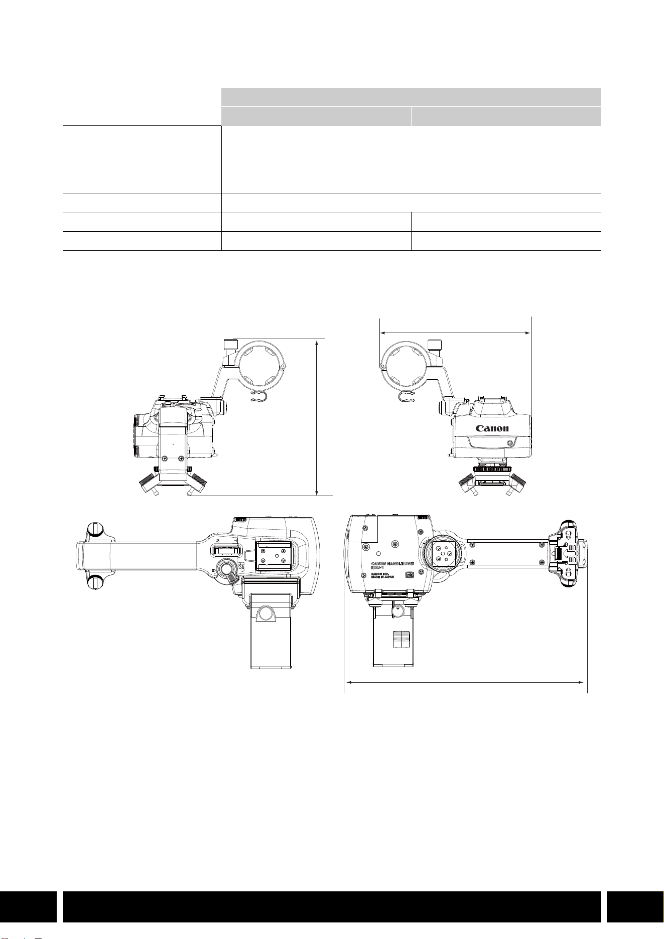
STILI DI RIPRESA E CONFIGURAZIONE
15
IT
Caratteristiche tecniche
* Peso e dimensioni approssimativi.
HDU-1 – misure dettagliate
Maniglia
HDU-1 HDU-3
Terminali INPUT 1, INPUT 2 Connettore XLR 3 pin (pin1: shield, pin2: hot, pin3: cold), 2 set (bilanciato)
Sensibilità:
Impostazione MIC: –60 dBu (centro volume, fondo scala –18 dB)
Impostazione LINE: 4 dBu (centro volume, fondo scala –18 dB)
Attenuatore: 20 dB
Temperatura di funzionamento Da 0 °C a 40 °C
Dimensioni* (L × A × P) 112 × 115 × 180 mm 112 × 139 × 197 mm
Peso* 253 g 305 g
mm
115
112
180


ÍNDICE
2
ES
3 Introducción
4 Accesorios y cámaras compatibles que se mencionan en esta guía del usuario
5 Comunicaciones
5 Receptor GPS GP-E2
7 Funcionalidad agregada y compatibilidad de objetivos
7 Convertidor de teleobjetivo TL-H58 / TL-U58
9 Accesorio de objetivo de ángulo ancho WA-H58 / WA-U58
12 Estilos de disparo y configuración
12 Asa HDU-1 / HDU-3
Índice
INTRODUCCIÓN
3
ES
Introducción
Esta guía del usuario trata sobre los accesorios opcionales compatibles con las cámaras Canon.
Proporciona información sobre cómo usar los accesorios, su compatibilidad y especificaciones.
Asegúrese de leer esta información, además de los manuales de instrucciones suministrados, para usar
los productos correctamente.
Antes de usar los accesorios
•A menos que se especifique lo contrario, la cámara suministra alimentación a los accesorios.
•Es posible que su cámara no sea compatible con todas las características y las funciones de cámara
descritas en esta guía. Consulte también el manual de instrucciones de la cámara utilizada.
•Algunos de los accesorios y las herramientas mencionados en esta guía pueden suministrarse con
algunos modelos de cámara. Consulte la lista de accesorios suministrados en el manual de
instrucciones de la cámara utilizada.
Si no se suministra un accesorio/herramienta con la cámara o con el producto que se explica, utilice un
accesorio opcional o un producto disponible en el comercio.
Convenciones en este documento
• Precauciones importantes relacionadas con el funcionamiento del producto.
• Información adicional que complementa los procedimientos básicos de funcionamiento.
•0 Número de página de referencia en este documento.
•“Cámara” se refiere a una cámara o videocámara Canon compatible (0 4).
•Este es un documento multilingüe. Puede hacer clic en el código de idioma en cualquier
página para volver al comienzo de la guía (Índice) en ese idioma.
•Tenga cuidado de no dejar caer la cámara ni los accesorios al colocar, quitar o ajustar los
distintos accesorios. Use una mesa u otra superficie estable.
•No conecte/acople accesorios a cámaras y dispositivos que no sean compatibles con ellos.
ES
La información de este documento está verificada a fecha de enero de 2024 y está sujeta a cambios sin
previo aviso.
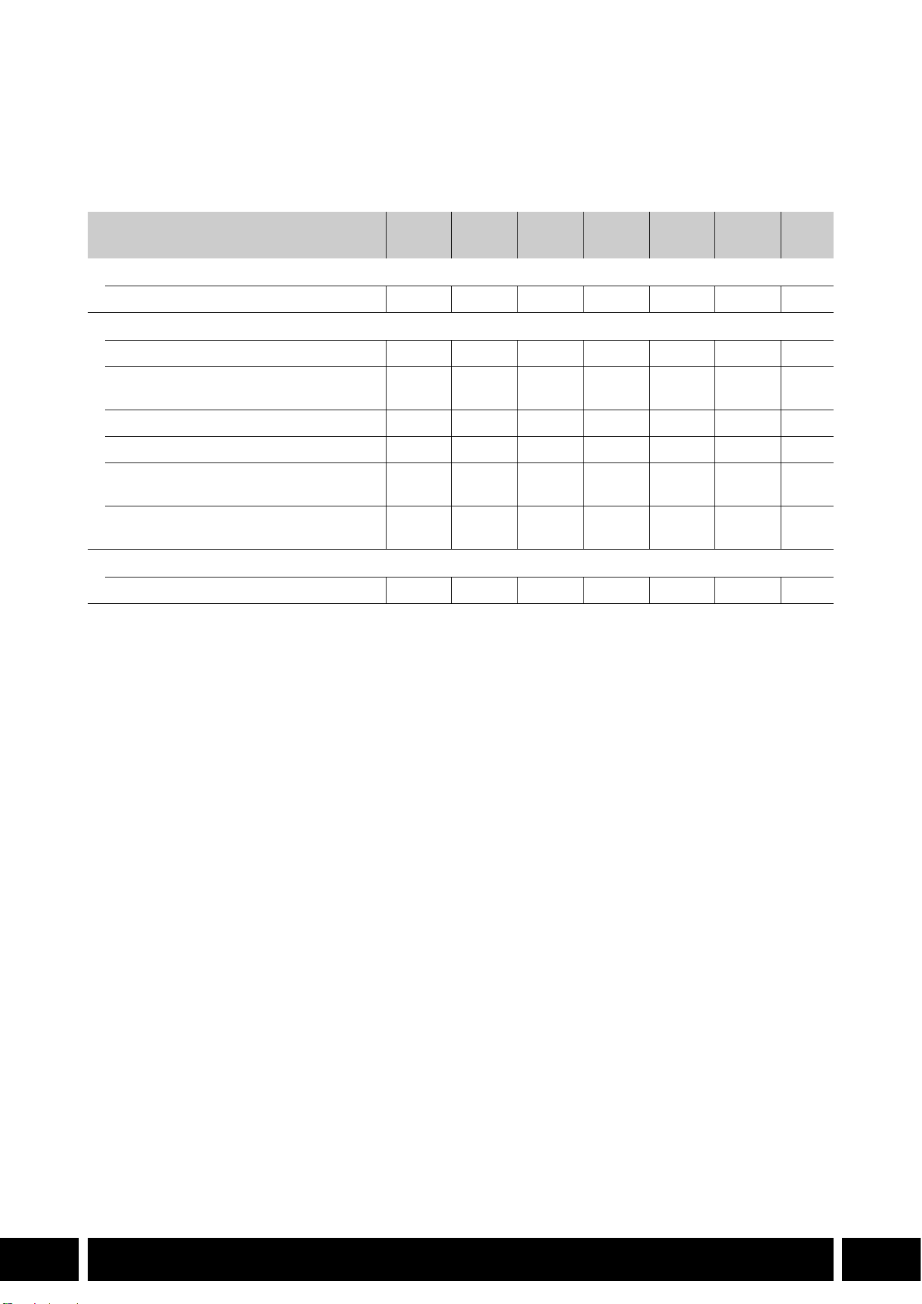
ACCESORIOS Y CÁMARAS COMPATIBLES QUE SE MENCIONAN EN ESTA GUÍA DEL USUARIO
4
ES
Accesorios y cámaras compatibles que se
mencionan en esta guía del usuario
En la siguiente tabla se indican los principales accesorios que amplían la funcionalidad de la cámara.
1
Para obtener más detalles, consulte el manual de instrucciones de la cámara y del accesorio en uso.
2
Este producto es de clase A. En un entorno doméstico este producto puede causar radiointerferencias, en cuyo
caso se puede solicitar al usuario que tome las medidas pertinentes.
Accesorio XF705 XF605
XA75 /
XA70
XA65 /
XA60
XA55 /
XA50
XA45 /
XA40
0
Comunicaciones
Receptor GPS GP-E2 NNNNNN5
Funcionalidad agregada y compatibilidad de objetivos
Controlador remoto RC-V100 NNNNNN—
1
Remote Camera Controller
RC-IP100
2
/ RC-IP1000
2
N —
1
Controlador inalámbrico WL-D89 N —
1
Controlador inalámbrico WL-D6000 N —
1
Convertidor de teleobjetivo
TL-H58 / TL-U58
TL-U58 TL-U58 TL-U58 TL-H58 TL-U58 TL-H58 7
Accesorio de objetivo de ángulo ancho
WA-H58 / WA-U58
WA-U58 WA-U58 WA-U58 WA-H58 WA-U58 WA-H58 9
Estilos de disparo y configuración
Asa HDU-1 / HDU-3 HDU-3 HDU-1 12
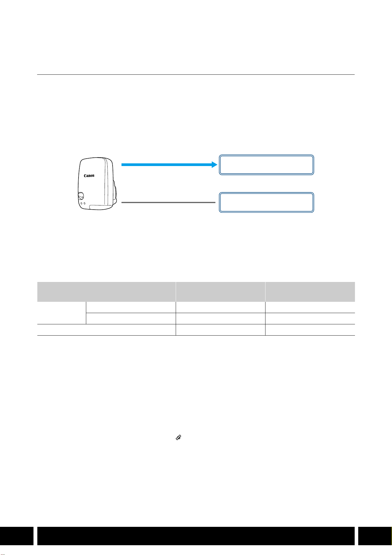
COMUNICACIONES
5
ES
Comunicaciones
Receptor GPS GP-E2
Conecte el receptor GPS a la zapata multifunción o el terminal USB de la cámara en modo CAMERA
(grabación) para registrar la información del GPS (latitud, longitud, altitud) con los metadatos de los clips y
las fotos. Si conecta el receptor al terminal USB de la cámara mientras graba, se recomienda colocar el
receptor en el estuche de transporte suministrado y sujetarlo a la correa para la empuñadura de la cámara
o llevarlo consigo. Para utilizar el GP-E2 se requiere una batería AA.
Para obtener más detalles sobre cómo conectar y configurar el receptor, consulte el manual de
instrucciones del GP-E2.
Cuando utilice una cámara con un terminal USB Tipo C, se requiere un cable de interfaz IFC-40AB III o
IFC-150AB III (se vende por separado). En función de la cámara, puede ser necesario ajustar la
configuración del terminal USB. Para obtener más detalles, consulte el manual de instrucciones de la
cámara utilizada.
Información registrada
* Puede utilizar la información del GPS para buscar y organizar clips con Canon XF Utility.
Conexión y activación del receptor GPS
1. Apague el receptor.
2. Conecte el receptor a la cámara.
•Use la zapata multifunción de la cámara, el cable USB suministrado con el GP-E2 o un cable de
interfaz opcional.
3. Encienda el receptor.
•La función GPS está activada. El icono aparece en la pantalla y parpadeará cuando el receptor
intente adquirir señales de satélite.
•Cuando las señales de satélite se adquieren correctamente, el icono permanecerá encendido
continuamente. Los clips y las fotos grabados después de ello se etiquetarán geográficamente.
Formato de grabación
Información de GPS
(latitud, longitud, altitud)
Horario universal coordinado
(UTC)
Clips
MP4 NN
XF-AVC* N —
Fotos NN
Cable USB
(suministrado con el GP-E2)
Terminal USB
(acoplar directamente)
o
Zapata multifunción

COMUNICACIONES
6
ES
•No conecte el GP-E2 a la zapata multifunción y el terminal USB de la cámara al mismo tiempo.
•En ciertos países/regiones, el uso de GPS puede estar restringido. Asegúrese de usar el
receptor GPS de acuerdo con las leyes y normativas locales del país/región donde se usa el
receptor. Tenga especial cuidado cuando viaje fuera de su país de origen.
•Tenga cuidado con el uso de funciones de GPS donde el funcionamiento de dispositivos
electrónicos está restringido.
•La información del GPS grabada con clips y fotos puede contener datos que pueden llevar a
otros a localizarlo o identificarlo. Tenga cuidado al compartir grabaciones etiquetadas
geográficamente con otras personas o al subirlas a la web.
•No deje el receptor cerca de potentes campos electromagnéticos, como cerca de imanes y
motores.
•La información del GPS grabada con clips corresponde a la ubicación al comienzo de la
grabación.
•Puede ajustar automáticamente la configuración de fecha y hora de la cámara de acuerdo con
la información recibida de la señal GPS. Consulte la tabla de ajustes del menú [Configuración
de sistema] en el manual de instrucciones de la cámara utilizada.
•La recepción inicial de la señal GPS llevará más tiempo después de reemplazar la batería del
receptor o al encender el receptor por primera vez después de un período prolongado de
haber estado apagado.
•No coloque cables conectados a los terminales de la cámara cerca del receptor. Hacerlo
puede afectar de forma negativa a la señal del GPS.
•Solo cámaras con pantallas de estado: puede verificar la información del GPS que se recibe y
la intensidad de la señal del satélite en las pantallas de estado. Para obtener más detalles,
consulte el manual de instrucciones de la cámara utilizada.
•La cámara no es compatible con las siguientes funciones del receptor.
–La opción [Ajust. ahora] para la función de ajuste automático de fecha
–Función de brújula digital
–Función de intervalo de posicionamiento
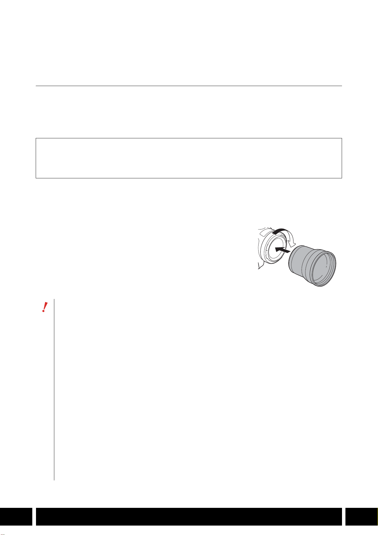
FUNCIONALIDAD AGREGADA Y COMPATIBILIDAD DE OBJETIVOS
7
ES
Funcionalidad agregada y compatibilidad de
objetivos
Convertidor de teleobjetivo TL-H58 / TL-U58
El uso del convertidor de teleobjetivo TL-H58/TL-U58 con una cámara Canon aumenta la distancia focal
del objetivo de la cámara en un factor de aproximadamente 1,5. En función de la cámara, el método de
estabilización de imagen y la distancia mínima del objeto pueden cambiar. Para obtener más detalles
sobre las diversas funciones, consulte el manual de instrucciones de la cámara utilizada.
Acoplamiento de un convertidor de teleobjetivo a la cámara
En esta sección se explica cómo acoplar un convertidor de teleobjetivo a la cámara, utilizando el TL-U58
como ejemplo. Puede acoplar el TL-H58 siguiendo los mismos pasos.
Enrosque el convertidor por completo en la rosca para filtros del
objetivo.
Accesorios suministrados
Estuche
Tapa del objetivo
Tapa contra el polvo
•No apunte el objetivo hacia el sol cuando el convertidor esté acoplado a la cámara. Esto podría
dañar el equipo.
•El convertidor no puede usarse al mismo tiempo que otros filtros ni que el parasol de la cámara.
•Utilice un trípode para evitar borrosidad de las imágenes.
•Limpie las superficies del convertidor y de la cámara antes del uso. De lo contrario, puede que
la cámara se enfoque incorrectamente sobre partículas de polvo o sobre otros cuerpos
presentes en la superficie del objetivo.
•El uso del convertidor puede obstruir la lámpara indicadora frontal*, reducir el alcance efectivo
del controlador inalámbrico o causar la aparición de una sombra al grabar usando una antorcha
para vídeo opcional*.
* No todos los modelos de cámara tienen lámpara indicadora ni son compatibles con las antorchas de
vídeo opcionales.
•Al grabar en gran angular máximo (W) con el convertidor acoplado, dependiendo del modelo
de la cámara, es posible que el marco del objetivo aparezca alrededor del borde exterior de la
imagen.
•Tenga cuidado al manipular el convertidor para evitar manchas o impresiones digitales.
•No guarde el convertidor en un lugar húmedo porque puede aparecer moho.
•Recomendamos que acople el convertidor a la cámara antes de ajustar el balance de blancos.

FUNCIONALIDAD AGREGADA Y COMPATIBILIDAD DE OBJETIVOS
8
ES
Especificaciones
Dimensiones detalladas de TL-H58
Dimensiones detalladas de TL-U58
Convertidor de teleobjetivo
TL-H58 TL-U58
Magnificación 1,5× 1,5×
Configuración del objetivo 5 elementos en 3 grupos 5 elementos en 3 grupos
Diámetro del filtro 58 mm 58 mm
Dimensiones ∅ 69 × 64 mm (largo) ∅ 79 × 69 mm (largo)
Peso Aprox. 273 g Aprox. 350 g
mm
ø 69
64
U58
mm
ø 79
69
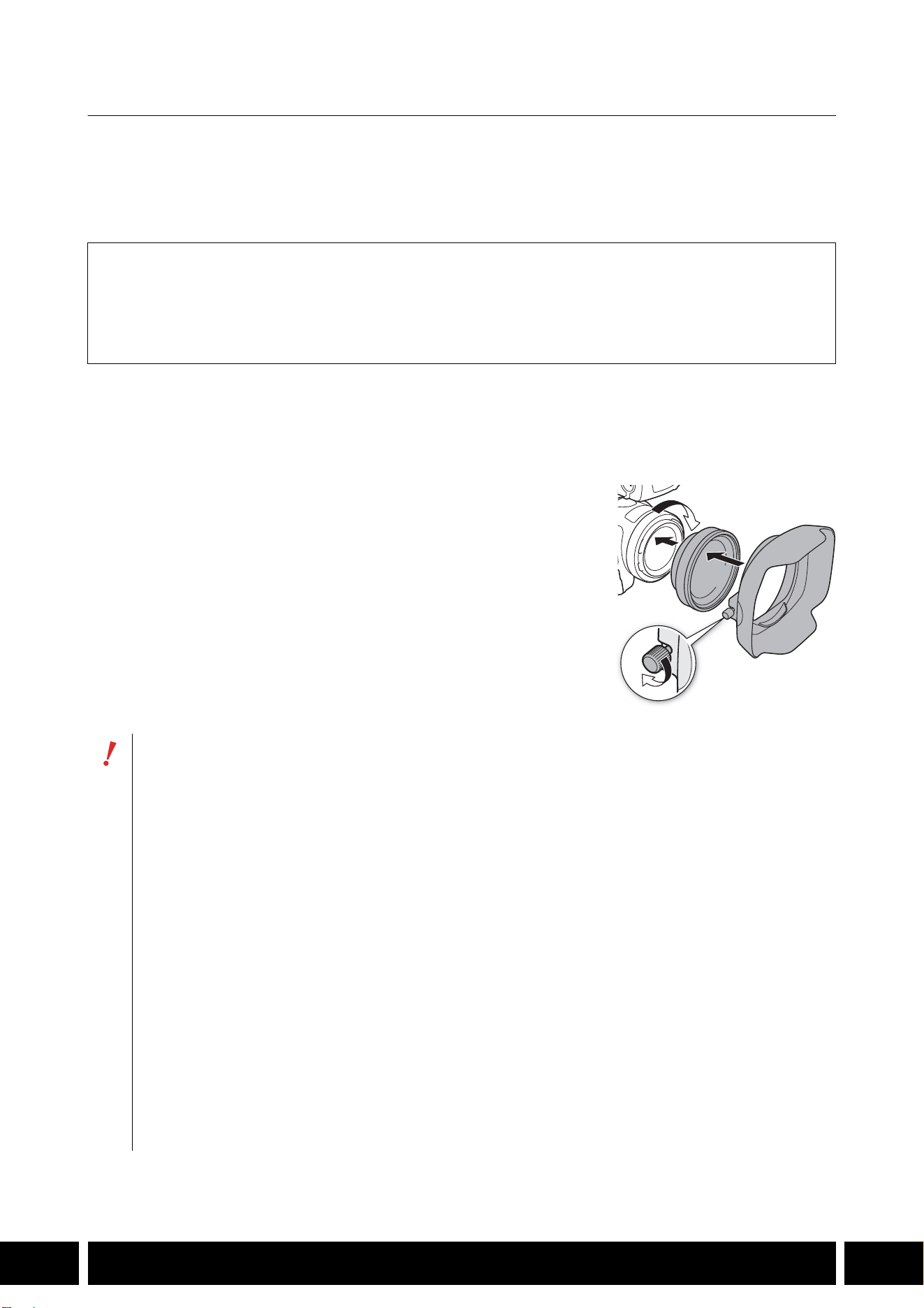
FUNCIONALIDAD AGREGADA Y COMPATIBILIDAD DE OBJETIVOS
9
ES
Accesorio de objetivo de ángulo ancho WA-H58 / WA-U58
El accesorio de objetivo de ángulo ancho WA-H58/WA-U58 le permite grabar vídeos y tomar fotos con un
ángulo de visión más amplio. En función de la cámara, el método de estabilización de imagen y la
distancia mínima del objeto pueden cambiar. Para obtener más detalles sobre las diversas funciones,
consulte el manual de instrucciones de la cámara utilizada.
Acoplamiento de un accesorio de objetivo de ángulo ancho a la cámara
En esta sección se explica cómo acoplar un accesorio de objetivo a la cámara, utilizando el WA-U58
como ejemplo. Puede acoplar el WA-H58 siguiendo los mismos pasos.
1. Retire el parasol suministrado con la cámara y fije el accesorio
de objetivo completamente dentro de la rosca de filtro del
objetivo (햲).
2. Fije el parasol suministrado con el accesorio de objetivo al
frente del accesorio de objetivo y apriete el tornillo de bloqueo
(햳).
•Fije el parasol en línea recta, prestando atención para no dañarlo.
Si el parasol está torcido o deformado, su sombra podría
aparecer en la imagen.
Accesorios suministrados
Estuche
Tapa del objetivo
Tapa contra el polvo
Parasol
•Al utilizar el accesorio de objetivo, la periferia exterior de la imagen puede aparecer retorcida.
•El accesorio de objetivo no puede usarse al mismo tiempo que otros filtros ni que el parasol de
la cámara.
•Limpie las superficies del accesorio de objetivo y de la cámara antes del uso. De lo contrario,
puede que la cámara se enfoque incorrectamente sobre partículas de polvo o sobre otros
cuerpos presentes en la superficie del objetivo.
•El uso del accesorio de objetivo puede obstruir la lámpara indicadora frontal*, reducir el alcance
efectivo del controlador inalámbrico o causar la aparición de una sombra al grabar usando una
antorcha de vídeo opcional*.
* No todos los modelos de cámara tienen lámpara indicadora ni son compatibles con las antorchas de
vídeo opcionales.
•Tenga cuidado cuando manipule el accesorio de objetivo para evitar manchas o impresiones
dactilares.
•Asegúrese de fijar la tapa del objetivo cuando almacene el accesorio de objetivo.
•No almacene el accesorio de objetivo en un lugar húmedo porque puede aparecer moho.
•Cuando ajuste el balance de blancos, se recomienda primero fijar el accesorio de objetivo a la
cámara y luego ajustar el balance de blancos.
햲
햳

FUNCIONALIDAD AGREGADA Y COMPATIBILIDAD DE OBJETIVOS
10
ES
Especificaciones
Dimensiones detalladas de WA-H58
Accesorio de objetivo de ángulo ancho
WA-H58 WA-U58
Magnificación Aprox. 0,75× Aprox. 0,8×
Configuración del objetivo 2 elementos en 2 grupos 2 elementos en 2 grupos
Diámetro del filtro 58 mm 58 mm
Dimensiones ∅ 79 × 28 mm (largo)
(sin el parasol)
144 × 102 × 68 mm
(An × Al × Pr) (con el parasol acoplado)
∅ 85 × 33 mm (largo)
(sin el parasol)
150 × 106 × 72 mm
(An × Al × Pr) (con el parasol acoplado)
Peso 260 g (sin el parasol)
310 g (con el parasol acoplado)
325 g (sin el parasol)
380 g (con el parasol acoplado)
mm
ø 79
68
28
144
102
50
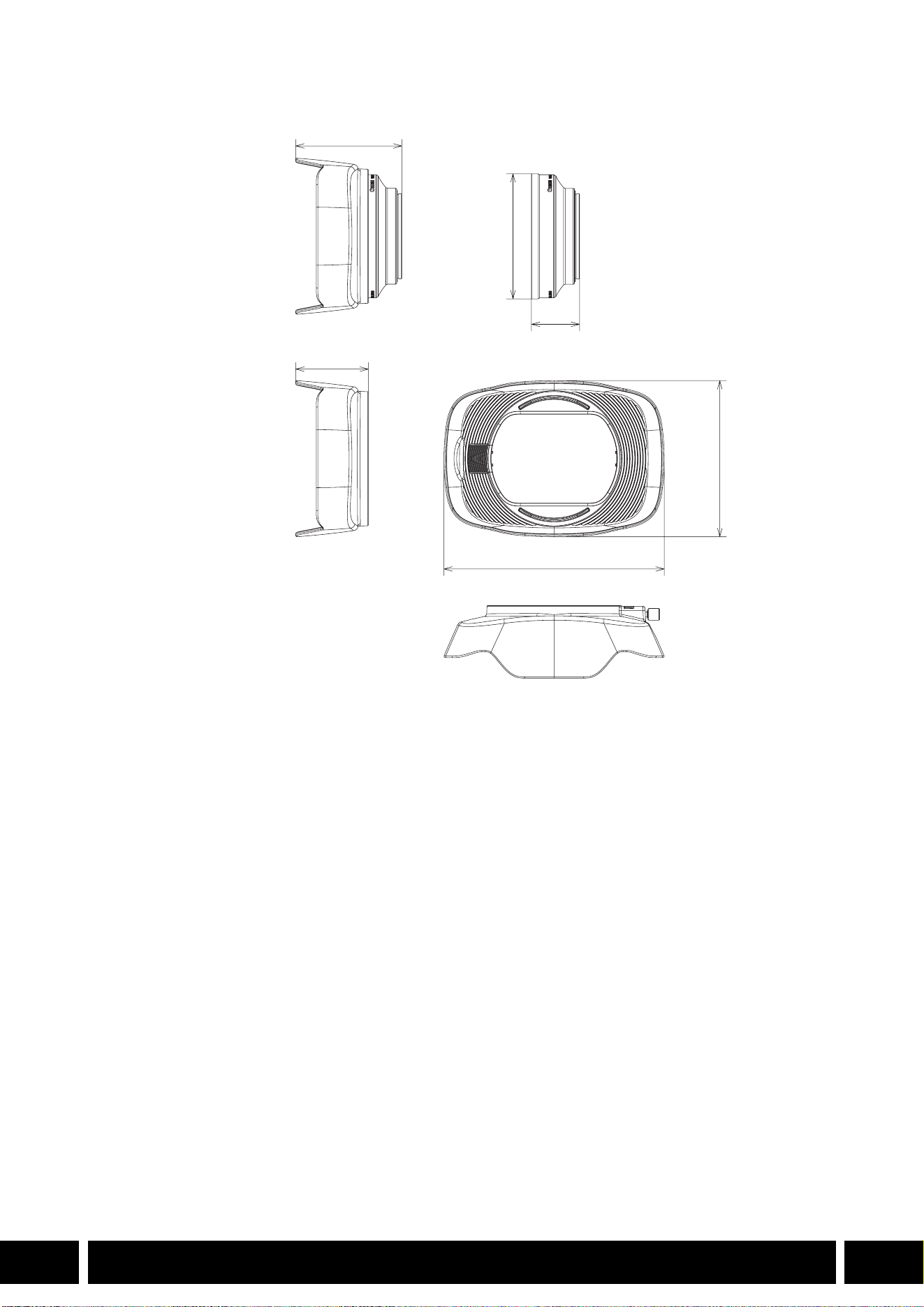
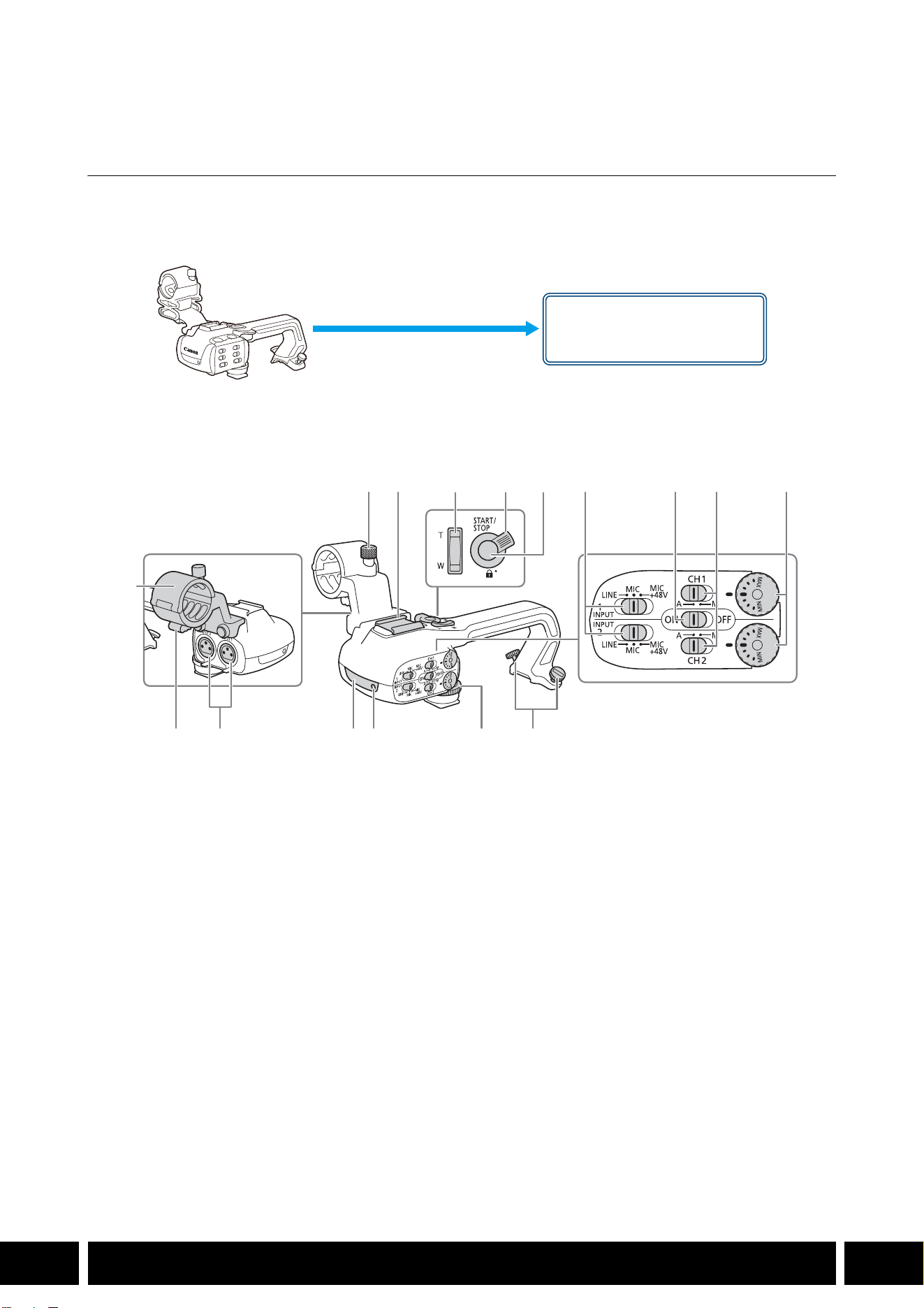
ESTILOS DE DISPARO Y CONFIGURACIÓN
12
ES
Estilos de disparo y configuración
Asa HDU-1 / HDU-3
Si conecta el asa a la cámara, puede utilizar el terminal INPUT, la luz infrarroja y la lámpara indicadora.
Para obtener más detalles sobre cómo conectar y usar el asa, consulte el manual de instrucciones de la
cámara utilizada.
Nombres de las partes
HDU-1
1 Unidad de soporte del micrófono
2 Tornillo de fijación del micrófono
3 Zapata para accesorio
4 Palanca de zoom del asa
5 Palanca de bloqueo START/STOP (C)
6 Botón START/STOP
7 Selectores de sensibilidad para INPUT 1 e
INPUT 2
8 Selector ON/OFF (activados/desactivados) de
los terminales INPUT
9 Selectores de nivel de audio para CH1 y CH2
10 Diales de nivel de audio para CH1 y CH2
11 Abrazadera del cable del micrófono
12 Terminales INPUT 1 e INPUT 2
13 Luz infrarroja
14 Lámpara indicadora
15 Tornillo frontal del asa
16 Tornillos traseros del asa
Montura del asa
(acoplar directamente)
23 7 8 9 10
161514131211
1
456
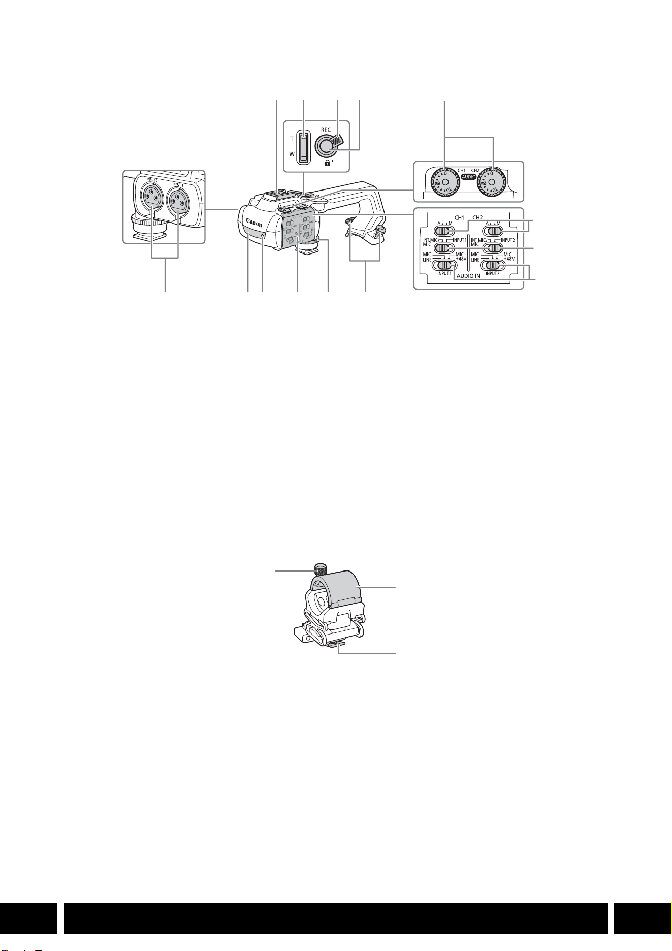
ESTILOS DE DISPARO Y CONFIGURACIÓN
13
ES
HDU-3
Soporte del micrófono (suministrado con la HDU-3)
1 Zapata para accesorios
2 Palanca de zoom del asa
3 Bloqueo del botón REC (C)
4 Botón REC (iniciar/detener grabación)
5 Diales de nivel de audio: para CH1 (izquierdo) y
CH2 (derecho)
6 Selectores de nivel de audio para CH1
(izquierdo) y CH2 (derecho)
7 Interruptores AUDIO IN (selección de entrada
de audio): para CH1 (izquierdo) y CH2
(derecho)
8 Selectores INPUT 1 (izquierdo) / INPUT 2
(derecho) - selección de fuente de audio
9 Terminales INPUT: INPUT 1 (derecho), INPUT 2
(izquierdo)
10 Luz infrarroja
11 Lámpara indicadora
12 Cubierta de controles de audio
13 Tornillo frontal del asa
14 Tornillos traseros del asa
1 Tornillo de fijación del micrófono
2 Soporte del micrófono
3 Abrazadera del cable del micrófono
1
7
8
91011121314
234
5
6
1
2
3

ESTILOS DE DISPARO Y CONFIGURACIÓN
14
ES
Acoplamiento del asa
En esta sección se explica cómo acoplar un asa a la cámara, utilizando la HDU-3 como ejemplo. Puede
acoplar la HDU-1 siguiendo los mismos pasos.
1. Apague la cámara.
2. Coloque la unidad de soporte del micrófono en el asa.
•Use un destornillador de cabeza Phillips (“de estrella”)
disponible en el mercado y los dos tornillos suministrados.
3. Alinee el asa con la unidad de fijación del asa y luego
deslice el asa hacia delante hasta el final.
4. Apriete firmemente los tornillos delantero y traseros.
•Para ajustar los tornillos traseros puede utilizar una
moneda u objeto similar.
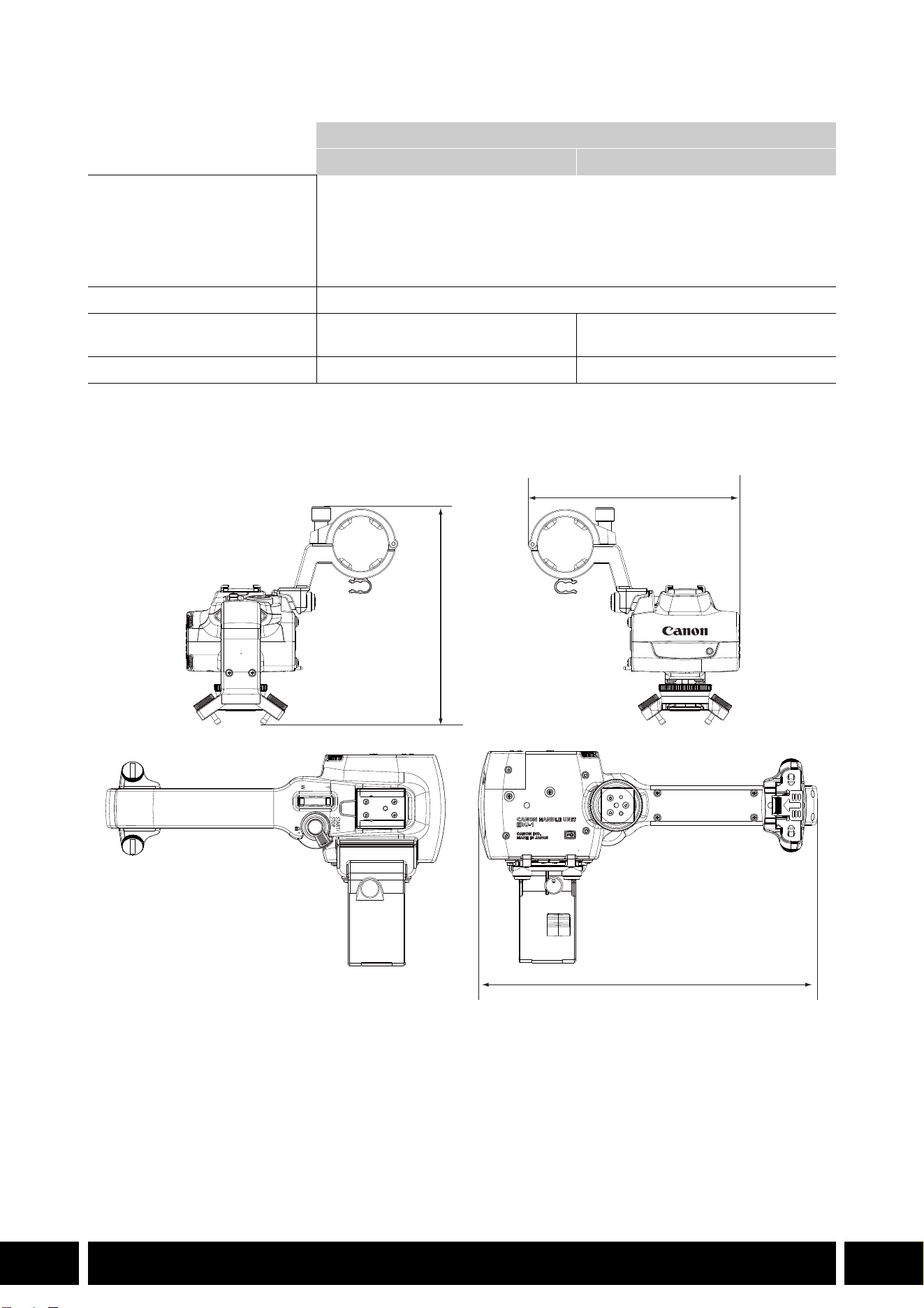
ESTILOS DE DISPARO Y CONFIGURACIÓN
15
ES
Especificaciones
* Todas las dimensiones y los pesos son aproximados.
Dimensiones detalladas de HDU-1
Asa
HDU-1 HDU-3
Terminales INPUT 1, INPUT 2 Conector XLR de 3 pines (clavija1: pantalla, clavija2: activo, clavija3: invertido),
2 juegos (balanceado)
Sensibilidad:
Ajuste MIC: –60 dBu (centro de volumen, escala completa a –18 dB)
Ajuste LINE: 4 dBu (centro de volumen, escala completa a –18 dB)
Atenuador: 20 dB
Temperatura de funcionamiento 0 °C – 40 °C
Dimensiones*
(Ancho × Alto × Profundidad)
112 × 115 × 180 mm 112 × 139 × 197 mm
Peso* 253 g 305 g
mm
115
112
180


СОДЕРЖАНИЕ
2
RU
3 Введение
4 Принадлежности и совместимые камеры, упомянутые в этом руководстве
пользователя
5 Связь
5 Принимающее устройство GPS GP-E2
7 Дополнительные функциональные возможности и совместимость
с объективом
7 Телеконвертер TL-H58 / TL-U58
10 Широкоугольная насадка WA-H58 / WA-U58
14 Стили съемки и конфигурация
14 Блок рукоятки HDU-1 / HDU-3
Содержание
ВВЕДЕНИЕ
3
RU
Введение
В настоящем Руководстве пользователя рассматриваются дополнительные аксессуары,
совместимые с камерами Canon. Оно предоставляет информацию отом, как использовать
аксессуары, об их совместимости, а также технические характеристики. Обязательно прочитайте
эту информацию в дополнение к руководствам из комплекта поставки для правильного
использования этих изделий.
Перед использованием аксессуаров
•Если не указано иное, питание на аксессуары подается скамеры.
•Ваша камера может не поддерживать все функции, описываемые вэтом Руководстве. См.
также инструкцию по эксплуатации используемой камеры.
•Некоторые аксессуары и инструменты, упоминаемые впроцедурах данного Руководства, могут
поставляться только снекоторыми моделями камер. Проверьте список прилагаемых
аксессуаров вруководстве по эксплуатации используемой камеры.
Если аксессуар/инструмент не поставляется скамерой или сописываемым изделием,
используйте дополнительно поставляемый аксессуар или изделие, имеющееся впродаже.
Обозначения, используемые внастоящем документе
• Важные меры предосторожности, относящиеся кэксплуатации изделия.
• Дополнительная информация, дополняющая основные инструкции по выполнению
операций.
•0 Ссылка на номер страницы вэтом документе.
•Термин «камера» означает совместимую камеру или видеокамеру Canon (0 4).
•Это многоязычный документ. Чтобы вернуться кначалу руководства (Оглавление)
на конкретном языке, можно на любой странице нажать на код языка.
•Будьте осторожны, чтобы не уронить камеру или аксессуары при установке, снятии или
регулировке различных дополнительных принадлежностей. Используйте стол или
другую устойчивую поверхность.
•Не подключайте эти аксессуары к камерам и устройствам, не совместимым с ними, и не
устанавливайте на них.
RU
Информация, содержащаяся вданном документе, верна по состоянию на январь 2024г.
Информация может быть изменены без уведомления.
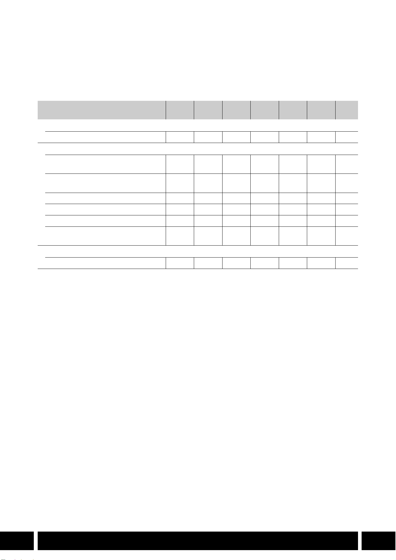
ПРИНАДЛЕЖНОСТИ И СОВМЕСТИМЫЕ КАМЕРЫ, УПОМЯНУТЫЕ В ЭТОМ РУКОВОДСТВЕ ПОЛЬЗОВАТЕЛЯ
4
RU
Принадлежности и совместимые камеры,
упомянутые в этом руководстве пользователя
В следующей таблице представлены основные принадлежности, расширяющие
функциональность камеры.
1
Подробные сведения см. в инструкции по эксплуатации камеры и принадлежностей.
2
Это изделие класса A. В домашних условиях это изделие может вызвать радиопомехи, в таком случае
пользователю может понадобиться принять соответствующие меры.
Аксессуар XF705 XF605
XA75 /
XA70
XA65 /
XA60
XA55 /
XA50
XA45 /
XA40
0
Связь
Принимающее устройство GPS GP-E2 NNNNNN5
Дополнительные функциональные возможности и совместимость с объективом
Пульт дистанционного управления
RC-V100
NNNNNN—
1
Панель Управления Дистанционной
Камерой RC-IP100
2
/ RC-IP1000
2
N —
1
Беспроводной пульт ДУ WL-D89 N —
1
Беспроводной пульт ДУ WL-D6000 N —
1
Телеконвертер TL-H58 / TL-U58 TL-U58 TL-U58 TL-U58 TL-H58 TL-U58 TL-H58 7
Широкоугольная насадка
WA-H58 / WA-U58
WA-U58 WA-U58 WA-U58 WA-H58 WA-U58 WA-H58 10
Стили съемки и конфигурация
Блок рукоятки HDU-1 / HDU-3 HDU-3 HDU-1 14
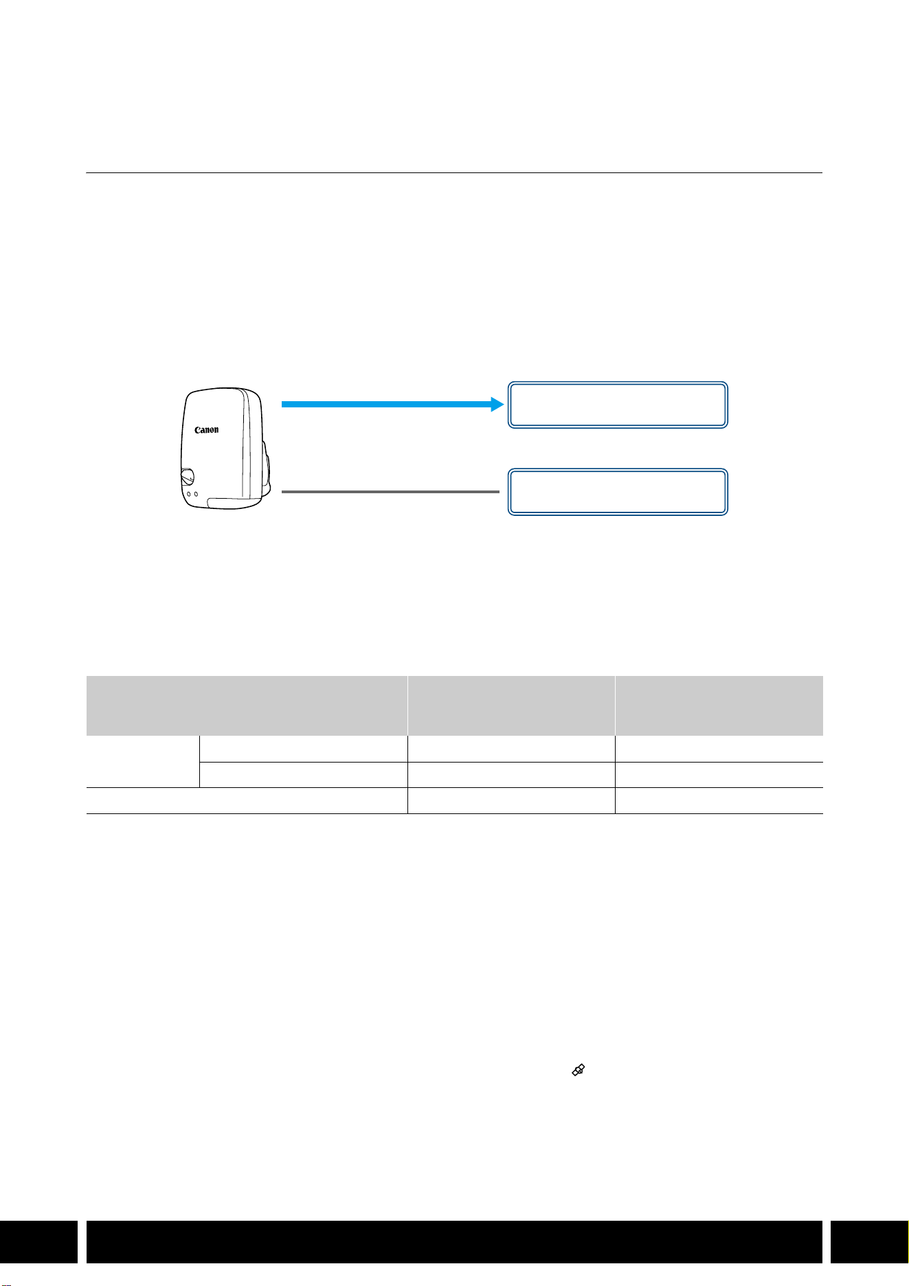
СВЯЗЬ
5
RU
Связь
Принимающее устройство GPS GP-E2
Подключите приемник GPS к многофункциональной колодке или разъему USB камеры в режиме
CAMERA (съемка), чтобы записать данные GPS (широту, долготу, высоту над уровнем моря) с
метаданными клипов и фотографий. Если приемник подключен к разъему USB камеры, во время
записи рекомендуется поместить приемник в прилагаемый футляр для переноски и прикрепить
его к ремню ручки камеры или носить на себе. Для использования GP-E2 необходима батарейка
размера АА.
За подробными сведениями об установке и настройке конфигурации приемника обратитесь
к руководству по эксплуатации GP-E2.
При использовании камеры с разъемом USB типа C требуется интерфейсный кабель IFC-40AB III
или IFC-150AB III (продаются отдельно). В зависимости от камеры может потребоваться
скорректировать настройки разъема USB. Подробнее см. в инструкции по эксплуатации
используемой камеры.
Записываемая информация
* Можно использовать данные GPS для поиска и организации клипов с помощью программного
обеспечения Canon XF Utility.
Подключение и активация приемника GPS
1. Выключите приемник.
2. Подключите приемник к камере.
•Используйте многофункциональную колодку камеры или USB-кабель, поставляемый с
GP-E2.
3. Включите приемник.
•Функция GPS активирована. На экране появляется значок , который будет мигать при
попытках приемника принять спутниковые сигналы.
•Когда спутниковые сигналы принимаются правильно, значок будет гореть постоянным
светом. Клипы и фотографии, записываемые после этого, будут содержать геотеги.
Формат записи
Данные GPS
(широта, долгота, высота над
уровнем моря)
Универсальное глобальное
время по Гринвичу
(UTC)
Клипы
MP4 NN
XF-AVC* N —
Фотографии NN
USB-кабель
(поставляется с GP-E2)
Разъем USB
(установить напрямую)
или
Многофункциональная
колодка

СВЯЗЬ
6
RU
•Не подключайте GP-E2 одновременно к многофункциональной колодке камеры и
разъему USB.
•В некоторых странах/регионах использование GPS может быть ограничено.
Обязательно используйте приемник GPS в соответствии с местными законами и
правилами страны/региона, где используется приемник. Будьте особенно осторожны,
путешествуя за пределами своей страны.
•Будьте осторожны при использовании функций GPS, когда работа электронных
устройств ограничивается.
•Информация GPS, записанная с клипами и фотографиями, может содержать данные,
которые могут привести к тому, что другие определят ваше местоположение или
идентифицируют вас. Будьте осторожны, когда делитесь записями, содержащими
геотеги, с другими или загружаете их в Интернет.
•Не оставляйте приемник поблизости от сильных электромагнитных полей, например
рядом с мощными магнитами и электродвигателями.
•Информация GPS, записываемая с клипами, соответствует местоположению на момент
начала записи.
•Можно сделать так, чтобы дата и время в камере регулировались автоматически
в соответствии с информацией, получаемой с сигналом GPS. См. таблицу настроек
в меню [Настройка системы] в руководстве по эксплуатации используемой камеры.
•Первоначальный прием GPS-сигнала займет больше времени после замены
аккумулятора приемника или при первом включении приемника после длительного
периода его выключения.
•Не размещайте кабели, подключенные к разъемам камеры, рядом с приемником. Это
может отрицательно повлиять на сигнал GPS.
•Только для камер со страницами состояния на экране: на страницах состояния можно
проверять полученные данные GPS и уровень сигнала спутника. Подробные сведения
см. в руководстве по эксплуатации используемой камеры.
•Камера несовместима со следующими функциями приемника:
–Опция [Устан.сейчас] для функции автоматической настройки даты.
–Функция цифрового компаса.
–Функция интервала позиционирования.
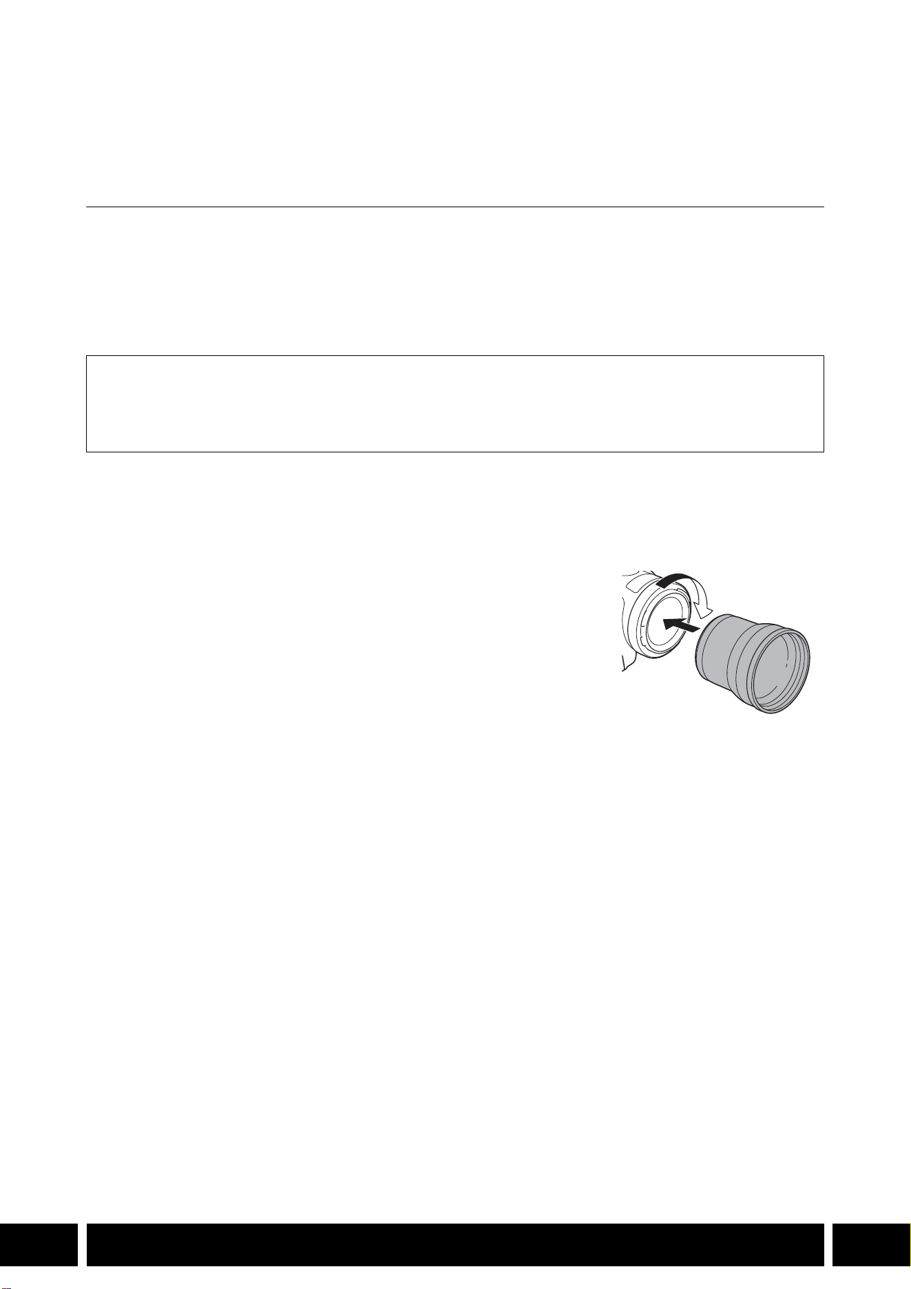
ДОПОЛНИТЕЛЬНЫЕ ФУНКЦИОНАЛЬНЫЕ ВОЗМОЖНОСТИ И СОВМЕСТИМОСТЬ С ОБЪЕКТИВОМ
7
RU
Дополнительные функциональные
возможности и совместимость с объективом
Телеконвертер TL-H58 / TL-U58
При использовании телеконвертера TL-H58/TL-U58 с камерой Canon фокусное расстояние
объектива камеры увеличивается приблизительно в 1,5 раза. В зависимости от камеры способ
стабилизации изображения и минимальное расстояние до объекта могут изменяться. За
подробными сведениями о различных функциях обратитесь к руководству по эксплуатации
используемой камеры.
Установка телеконвертера на камеру
В этом разделе описывается установка телеконвертера на камеру на примере TL-U58.
Телеконвертер TL-H58 устанавливается аналогично.
Навинтите телеконвертер до упора на резьбу для фильтров на
объективе.
Аксессуары из комплекта поставки
Мягкий футляр
Крышка объектива
Противопыльная крышка

ДОПОЛНИТЕЛЬНЫЕ ФУНКЦИОНАЛЬНЫЕ ВОЗМОЖНОСТИ И СОВМЕСТИМОСТЬ С ОБЪЕКТИВОМ
8
RU
•Не направляйте объектив на солнце, когда к камере присоединен телеконвертер. Это
может привести к выходу камеры из строя.
•Совместно с телеконвертером нельзя использовать другие фильтры или бленду
объектива камеры.
•Чтобы избежать смазывания изображения, используйте штатив.
•Перед началом работы очистите поверхность телеконвертера и объектив камеры. В
противном случае камера может ошибочно фокусироваться на частицах пыли или
других веществах, находящихся на поверхностях объективов.
•Телеконвертер может загораживать передний индикатор съемки*, при его
использовании возможно сокращение эффективного радиуса действия беспроводного
пульта ДУ или появление тени при съемке с применением дополнительно
приобретаемой осветительной лампы*.
* Не все модели камер имеют индикатор съемки или совместимы с дополнительно
приобретаемыми осветительными лампами.
•При съемке с фокусным расстоянием в максимально широкоугольном положении (W),
когда к камере присоединен телеконвертер, вокруг внешних краев картинки может
отображаться рамка объектива (это зависит от модели).
•При обращении с телеконвертером соблюдайте осторожность, не пачкайте его и не
оставляйте на нем отпечатки пальцев.
•Не храните телеконвертер в местах с повышенной влажностью. Он может покрыться
плесенью.
•Рекомендуется выполнять регулировку баланса белого после установки
телеконвертера на камеру.

ДОПОЛНИТЕЛЬНЫЕ ФУНКЦИОНАЛЬНЫЕ ВОЗМОЖНОСТИ И СОВМЕСТИМОСТЬ С ОБЪЕКТИВОМ
9
RU
Технические характеристики
Детальные размеры TL-H58
Детальные размеры TL-U58
Телеконвертер
TL-H58 TL-U58
Увеличение 1,5× 1,5×
Конструкция объектива 5 элементов в 3 группах 5 элементов в 3 группах
Диаметр фильтра 58 мм 58 мм
Габариты ∅ 69 мм × 64 мм (длина) ∅ 79 мм × 69 мм (длина)
Вес Прибл. 273 г Прибл. 350 г
мм
ø 69
64
U58
мм
ø 79
69
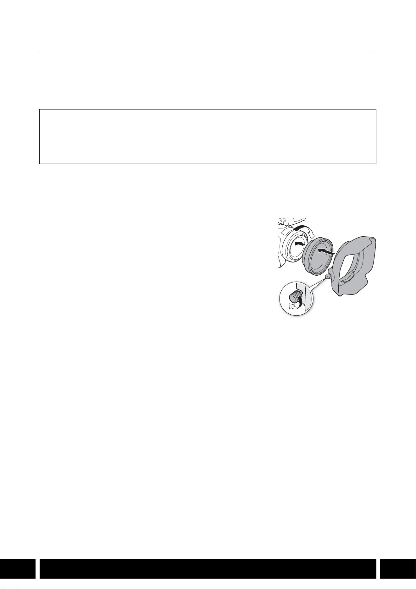
ДОПОЛНИТЕЛЬНЫЕ ФУНКЦИОНАЛЬНЫЕ ВОЗМОЖНОСТИ И СОВМЕСТИМОСТЬ С ОБЪЕКТИВОМ
10
RU
Широкоугольная насадка WA-H58 / WA-U58
Широкоугольная насадка WA-H58/WA-U58 позволяет снимать фильмы и фотографии с широким
углом обзора. В зависимости от камеры способ стабилизации изображения и минимальное
расстояние до объекта могут изменяться. За подробными сведениями о различных функциях
обратитесь к руководству по эксплуатации используемой камеры.
Установка широкоугольной насадки на камеру
В этом разделе описывается установка широкоугольной насадки на камеру на примере WA-U58.
Широкоугольная насадка WA-H58 устанавливается аналогично.
1. Снимите бленду, входящую в комплект поставки камеры,
и полностью навинтите широкоугольную насадку на
резьбу для фильтра объектива (햲).
2. Установите бленду, входящую в комплект поставки
широкоугольной насадки, на торец насадки и затяните
стопорный винт (햳).
•Устанавливайте бленду без перекосов, следя за тем, чтобы
не деформировать ее. Если бленда погнулась и изменила
свою форму, на изображении может появиться тень.
Аксессуары из комплекта поставки
Мягкий футляр
Крышка объектива
Противопыльная крышка
Бленда
햲
햳

ДОПОЛНИТЕЛЬНЫЕ ФУНКЦИОНАЛЬНЫЕ ВОЗМОЖНОСТИ И СОВМЕСТИМОСТЬ С ОБЪЕКТИВОМ
11
RU
•При использовании широкоугольной насадки наружные периферийные части
изображения могут выглядеть искаженными.
•Совместно с широкоугольной насадкой нельзя использовать другие фильтры или
бленду объектива камеры.
•Перед началом работы очистите поверхность широкоугольной насадки и объектив
камеры. В противном случае камера может ошибочно фокусироваться на частицах пыли
или других веществах, находящихся на поверхностях объективов.
•Широкоугольная насадка может загораживать передний индикатор съемки*, при ее
использовании возможно сокращение эффективного радиуса действия беспроводного
пульта ДУ или появление тени при съемке с применением дополнительно
приобретаемой осветительной лампы*.
* Не все модели камер имеют индикатор съемки или совместимы с дополнительно
приобретаемыми осветительными лампами.
•Соблюдайте осторожность при обращении с широкоугольной насадкой во избежание
появления пятен и следов пальцев.
•Убирая широкоугольную насадку на хранение, обязательно устанавливайте крышку
объектива.
•Не храните широкоугольную насадку во влажном месте. Она может покрыться
плесенью.
•При настройке баланса белого рекомендуется сначала установить на камеру
широкоугольную насадку, а потом настраивать баланс белого.

ДОПОЛНИТЕЛЬНЫЕ ФУНКЦИОНАЛЬНЫЕ ВОЗМОЖНОСТИ И СОВМЕСТИМОСТЬ С ОБЪЕКТИВОМ
12
RU
Технические характеристики
Детальные размеры WA-H58
Широкоугольная насадка
WA-H58 WA-U58
Увеличение Прибл. 0,75× Прибл. 0,8×
Конструкция объектива 2 элемента в 2 группах 2 элемента в 2 группах
Диаметр фильтра 58 мм 58 мм
Габариты ∅ 79 × 28 мм (длина)
(без бленды)
144 × 102 × 68 мм
(Ш × В × Г) (с надетой блендой)
∅ 85 × 33 мм (длина)
(без бленды)
150 × 106 × 72 мм
(Ш × В × Г) (с надетой блендой)
Вес 260 г (без бленды)
310 г (с надетой блендой)
325 г (без бленды)
380 г (с надетой блендой)
мм
ø 79
68
28
144
102
50


СТИЛИ СЪЕМКИ И КОНФИГУРАЦИЯ
14
RU
Стили съемки и конфигурация
Блок рукоятки HDU-1 / HDU-3
Если к камере подключен блок рукоятки, можно использовать разъем INPUT, инфракрасную
подсветку и индикатор съемки.
Сведения об установке и использовании блока рукоятки см. в инструкции по эксплуатации
используемой камеры.
Названия компонентов
HDU-1
1 Блок держателя микрофона
2 Винт фиксации микрофона
3 Колодка для аксессуаров
4 Рычаг зумирования на рукоятке
5 Рычаг блокировки (C) кнопки START/STOP
6 Кнопка START/STOP
7 Переключатели выбора чувствительности
для входов INPUT 1 и INPUT 2
8 Переключатель ON/OFF (Вкл./Откл.)
разъемов INPUT
9 Переключатели уровня громкости звука
для входов CH1 и CH2
10 Диски уровня громкости звука для входов
CH1 и CH2
11 Зажим кабеля микрофона
12 Разъемы INPUT 1 и INPUT 2
13 Инфракрасная лампа
14 Индикатор съемки
15 Передний винт блока рукоятки
16 Задние винты блока рукоятки
Крепление блока рукоятки
(установить напрямую)
23 7 8 9 10
161514131211
1
456

СТИЛИ СЪЕМКИ И КОНФИГУРАЦИЯ
15
RU
HDU-3
Блок держателя микрофона (из комплекта поставки блока HDU-3)
1 «Холодный башмак»
2 Рычаг зумирования на рукоятке
3 Рычаг блокировки (C) кнопки REC
4 Кнопка REC (запуск и остановка
видеосъемки)
5 Диски регулировки уровня звука: для CH1
(левый) и CH2 (правый)
6 Переключатели уровня звука: для CH1
(левый) и CH2 (правый)
7 Переключатели AUDIO IN (выбор звукового
входа): для CH1 (левый) и CH2 (правый)
8 Переключатели INPUT 1 (левый)/INPUT 2
(правый) (выбор источника звука)
9 Разъемы INPUT: INPUT 1 (правый), INPUT 2
(левый)
10 Инфракрасная лампа
11 Индикатор съемки
12 Крышка органов управления звуком
13 Передний винт блока рукоятки
14 Задние винты блока рукоятки
1 Стопорный винт микрофона
2 Держатель микрофона
3 Зажим кабеля микрофона
1
7
8
91011121314
234
5
6
1
2
3
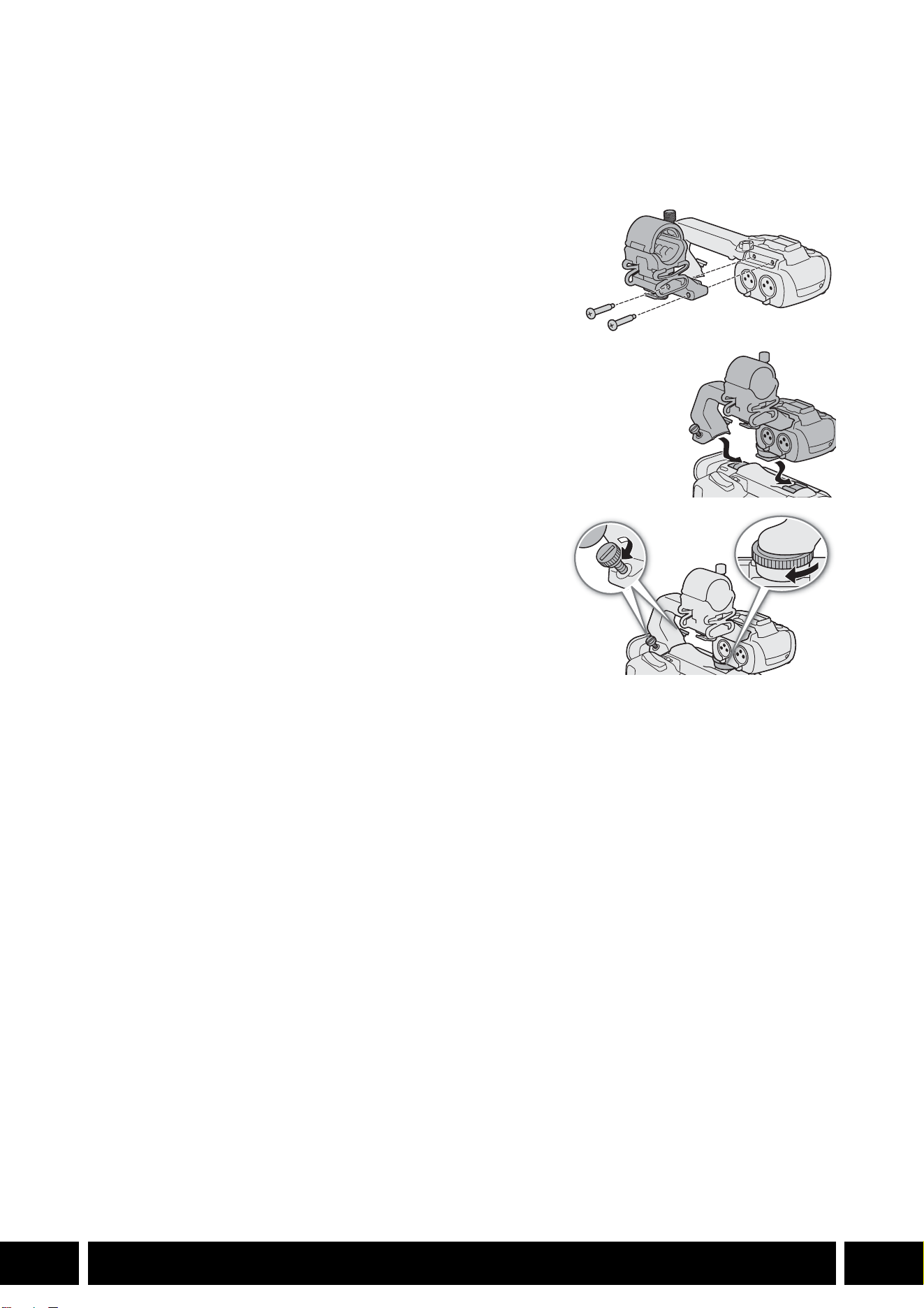
СТИЛИ СЪЕМКИ И КОНФИГУРАЦИЯ
16
RU
Установка блока рукоятки
В этом разделе описывается установка блока рукоятки на камеру на примере блока HDU-3. Блок
HDU-1 устанавливается аналогично.
1. Выключите камеру.
2. Закрепите блок держателя микрофона на блоке
рукоятки.
•Используйте крестовую отвертку (Phillips) из числа
имеющихся в продаже и два винта из комплекта
поставки.
3. Совместите блок рукоятки с блоком его крепления,
затем сдвиньте блок рукоятки вперед до упора.
4. Надежно затяните передний и задний винты.
•Задние винты можно затянуть с помощью монеты или
аналогичного предмета.
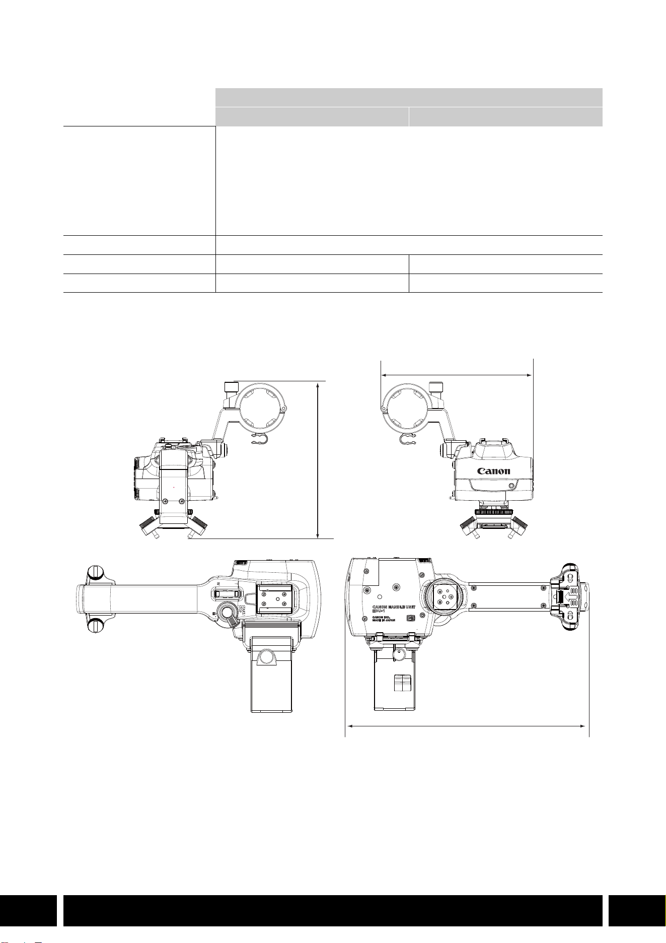
СТИЛИ СЪЕМКИ И КОНФИГУРАЦИЯ
17
RU
Технические характеристики
* Все размеры и значения веса приблизительные.
Детальные размеры HDU-1
Блок рукоятки
HDU-1 HDU-3
Разъемы INPUT 1 и INPUT 2 3-контактный разъем XLR (контакт 1: экран, контакт 2: горячий, контакт 3:
холодный), 2 набора (симметричный)
Чувствительность:
Настройка MIC: –60 dBu (центральное положение ручной регулировки
громкости, полный диапазон –18 дБ)
Настройка LINE: 4 dBu (центральное положение ручной регулировки
громкости, полный диапазон –18 дБ)
Аттенюатор: 20 дБ
Рабочая температура 0 °C – 40 °C
Габариты* (Ш × В × Г) 112 × 115 × 180 мм 112 × 139 × 197 мм
Вес* 253 г 305 г
мм
115
112
180


说明
3
ZH
说明
本用户指南的内容涵盖兼容佳能摄影机的选购附件。信息包括附件的使用方法、兼容性和规格。除产
品随附的使用说明书外,请务必认真阅读本指南,以便正确使用产品。
附件使用须知
• 除非另有说明,否则附件由摄影机供电。
• 您的摄影机可能不支持本指南中介绍的全部摄影机功能。另请参阅所用摄影机的使用说明书。
• 在本指南中提及的某些附件和工具可能是某些摄影机型号的随附附件。请在所用摄影机的使用说明
书中查看随附的附件列表。
如果摄影机或正在说明的产品不提供附件,请使用选购的附件或市售产品。
本文档使用的约定
• 产品操作的相关重要注意事项。
• 基本操作步骤的补充信息。
• 0 本文档中的参考页码。
•“摄影机”是指兼容的佳能摄影机或摄像机 (0 4)。
• 本文档是多语言合册。点击任何页面上的语言代码,都可以返回相应语言的指南首页
(目录 )。
本文档内信息的查证截止日期为 2024年 1月。因产品改进,规格或外观可能有所变更,敬请留意。
• 装卸或调整各种附件时,请小心以免摄影机或附件掉落。请使用桌子或其他平稳的表面。
• 请勿将附件连接 /安装至任何与之不兼容的摄影机及设备。
ZH
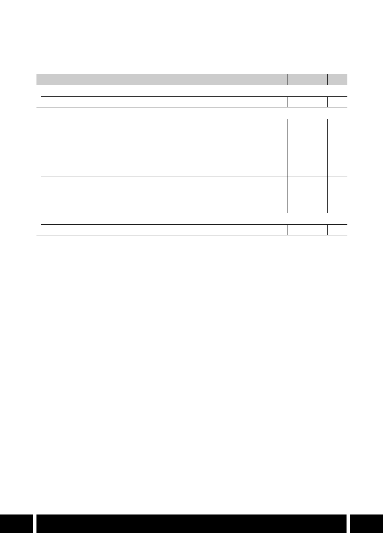
本指南中涵盖的附件和兼容摄影机
4
ZH
本指南中涵盖的附件和兼容摄影机
下表列出了可扩展摄影机功能的主要附件。
1
有关详细信息,请参阅所用摄影机和附件的使用说明书。
2
本产品为 A 类产品。在生活环境中,本产品可能会造成无线电干扰,此情况下,可能需要用户采取适当措施。
附件
XF705 XF605 XA75 / XA70 XA65 / XA60 XA55 / XA50 XA45 / XA40 0
通信
GP-E2 GPS接收器
NNNNNN5
新增功能和镜头兼容性
RC-V100遥控器
NNNNNN—
1
RC-IP100/RC-IP1000
摄控一体机控制器
2
N —
1
WL-D89 无线遥控器
N —
1
WL-D6000无线遥控
器
N —
1
TL-H58/TL-U58长
焦附加镜
TL-U58 TL-U58 TL-U58 TL-H58 TL-U58 TL-H58 7
WA-H58/WA-U58广
角辅助镜头
WA-U58 WA-U58 WA-U58 WA-H58 WA-U58 WA-H58 9
拍摄风格和配置
HDU-1/HDU-3手柄
HDU-3 HDU-1 12
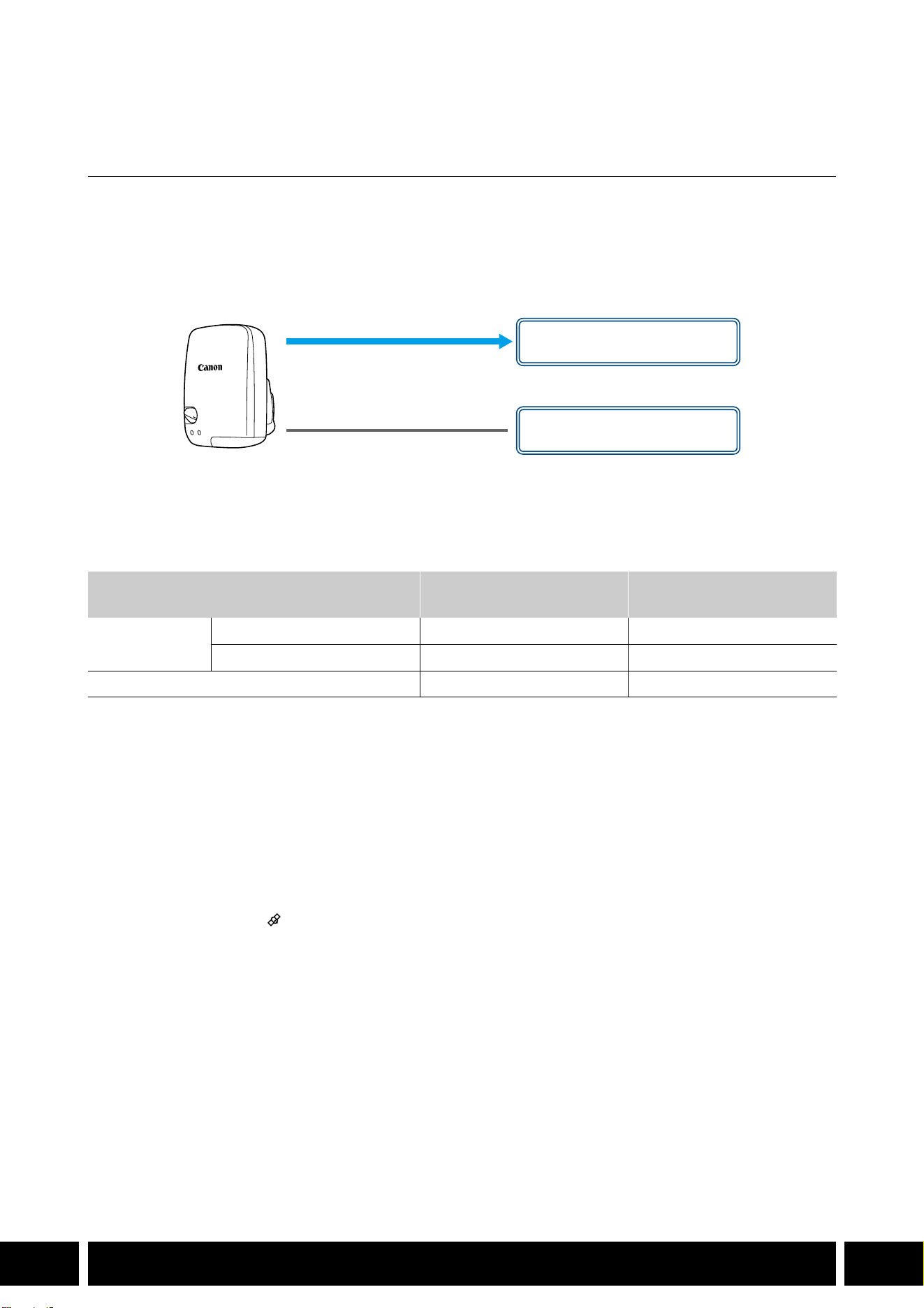
通信
5
ZH
通信
GP-E2 GPS 接收器
在 CAMERA ( 拍摄 )模式下,将 GPS接收器连接到摄影机的多功能靴或 USB端子可将 GPS信息 (纬
度、经度、海拔 )记录到短片和照片的元数据中。如果将接收器连接至摄影机的 USB端子,记录时,
推荐将接收器放入随附的便携袋中,然后将便携袋挂到摄影机的握带上或您自己携带该接收器。 要使
用 GP-E2需要 1节 AA电池 (5号电池 )。
有关安装和配置该接收器的详细信息,请参阅 GP-E2的使用说明书。
使用配备 Type-C USB 端子的摄影机时,需要 IFC-40AB III或 IFC-150AB III接口连接线 (另售 )。根
据摄影机的不同,可能需要调整 USB端子设置。有关详细信息,请参阅所用摄影机的使用说明书。
记录的信息
* 可以通过 Canon XF Utility使用 GPS信息来搜索和管理短片。
连接和启用 GPS 接收器
1. 关闭接收器。
2. 将接收器连接至摄影机。
• 请使用摄影机的多功能靴、随 GP-E2提供的 USB连接线或选购的接口连接线。
3. 开启接收器。
• GPS功能已启用。 图标出现在屏幕上,并在接收器尝试获取卫星信号时闪烁。
• 正确获取卫星信号后,图标将持续亮起。此后记录的短片和照片上将标有地理位置标记。
记录格式
GPS 信息
(纬度、经度、海拔 )
世界标准时间
(UTC)
短片
MP4 NN
XF-AVC* N —
照片
NN
USB连接线
(随 GP-E2提供 )
USB端子
(直接安装 )
或
多功能靴

通信
6
ZH
• 请勿将 GP-E2同时连接到摄影机的多功能靴和 USB端子上。
• 在某些国家和地区,GPS的使用可能受到限制。使用 GPS接收器时,请务必遵守使用接收
器时所在国家和地区的法律和法规。在国外旅游时,请特别注意。
• 在限制操作电子设备的地方,请谨慎使用 GPS功能。
• 记录在短片和照片中的 GPS 信息可能有能让他人找到或识别您所在位置的数据。与他人分
享带有地理位置信息的记录时或将其上传至网络时请务必小心。
• 请勿使接收器靠近强电磁场的地方,如强力的磁铁和电机。
• 短片上记录的 GPS信息与记录开始时的位置相同。
• 可以让摄影机根据从 GPS信号接收到的信息自动调整日期和时间设置。请参阅所用摄影机
的使用说明书中的 [系统设置 ]菜单设置表。
• 更换接收器电池或关闭接收器一段时间后首次开启时,初始GPS信号接收将花费更长时间。
• 请勿将连接到摄影机端子的连接线放在接收器附近。否则会对 GPS信号产生不良影响。
• 仅限有状态屏幕的摄影机:可以在状态屏幕上查看接收到的 GPS信息以及卫星信号强度。
有关详细信息,请参阅所用摄影机的使用说明书。
• 本摄影机不兼容接收器的下列功能。
– 自动日期调整功能的 [立即设置 ]选项
– 数字罗盘功能
– 定位间隔功能
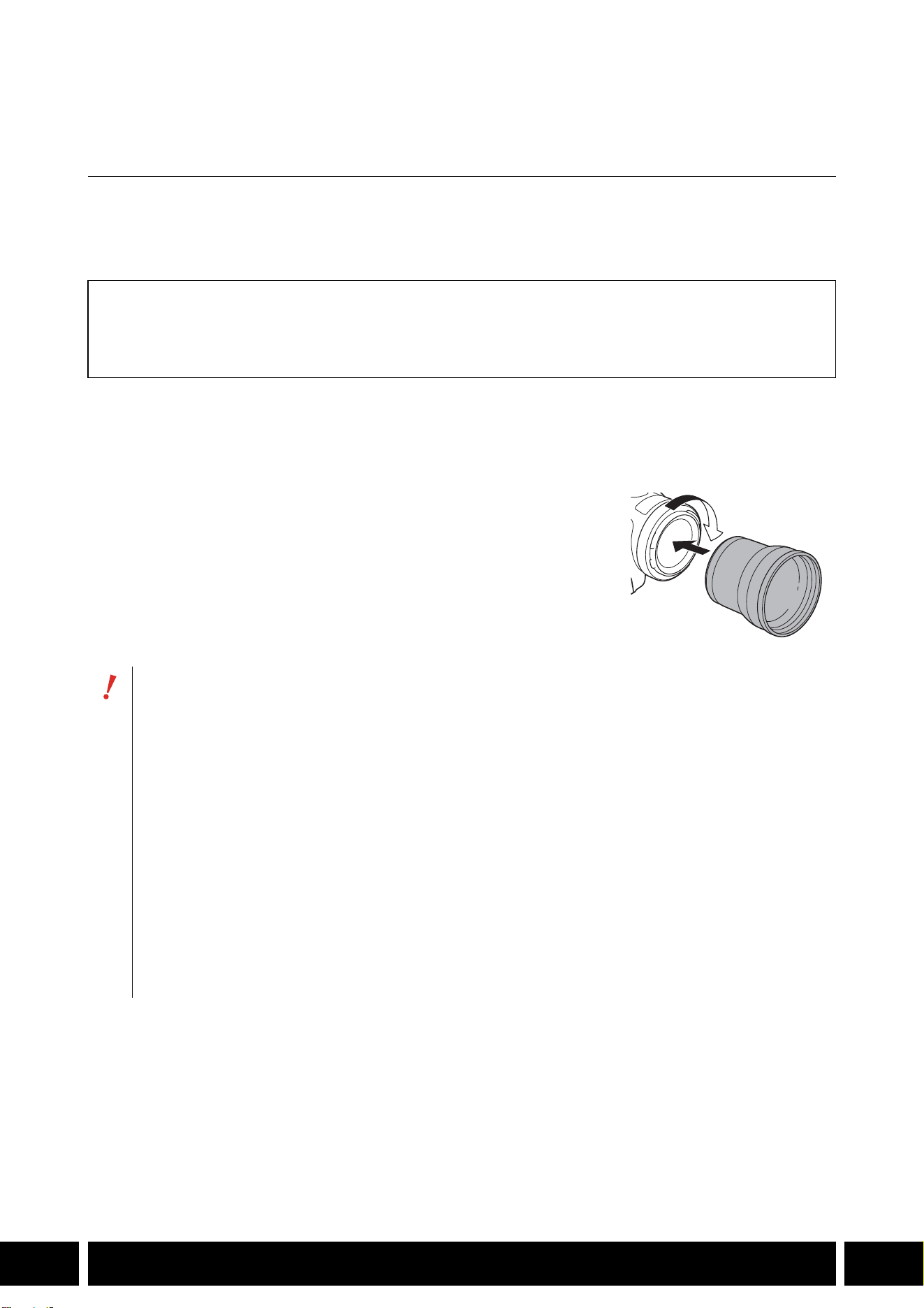
新增功能和镜头兼容性
7
ZH
新增功能和镜头兼容性
TL-H58/TL-U58 长焦附加镜
在佳能摄影机上使用 TL-H58/TL-U58长焦附加镜,摄影机镜头的焦距将按约 1.5的系数增加。根据
摄影机的不同,影像稳定方法和最小的被摄体距离可能会更改。有关各个功能的详情,请参阅所用
摄影机的使用说明书。
将长焦附加镜安装到摄影机
本节说明如何将长焦附加镜安装到摄影机,以 TL-U58为例。可以按照相同的步骤安装 TL-H58。
将长焦附加镜完全拧进镜头滤镜的螺纹部分。
随附的附件
软袋
镜头盖
防尘罩
• 长焦附加镜安装至摄影机时,请勿将镜头对着太阳。否则可能会损坏摄影机。
• 其他滤镜和摄影机的遮光罩不能与长焦附加镜同时使用。
• 请使用三脚架防止移动导致成像模糊。
• 使用前请清洁长焦附加镜和摄影机的镜头表面。否则,摄影机可能会对镜头表面的灰尘或
其他污物进行错误对焦。
• 使用长焦附加镜可能会影响前摄影指示灯 *,减小无线遥控器的有效作用范围,或在使用选
购的摄影灯 * 记录时导致阴影出现。
* 并非所有摄影机型号均配备摄影指示灯或均兼容选购的摄影灯。
• 根据摄像机型号的不同,使用长焦附加镜进行全广角 (W)拍摄时,镜头的边缘可能会出现
在图像周围。
• 使用长焦附加镜时需小心,避免弄脏或留下指纹印。
• 请勿将长焦附加镜存放在潮湿的地方。否则,可能会发霉。
• 建议在调整白平衡前将长焦附加镜安装至摄影机。
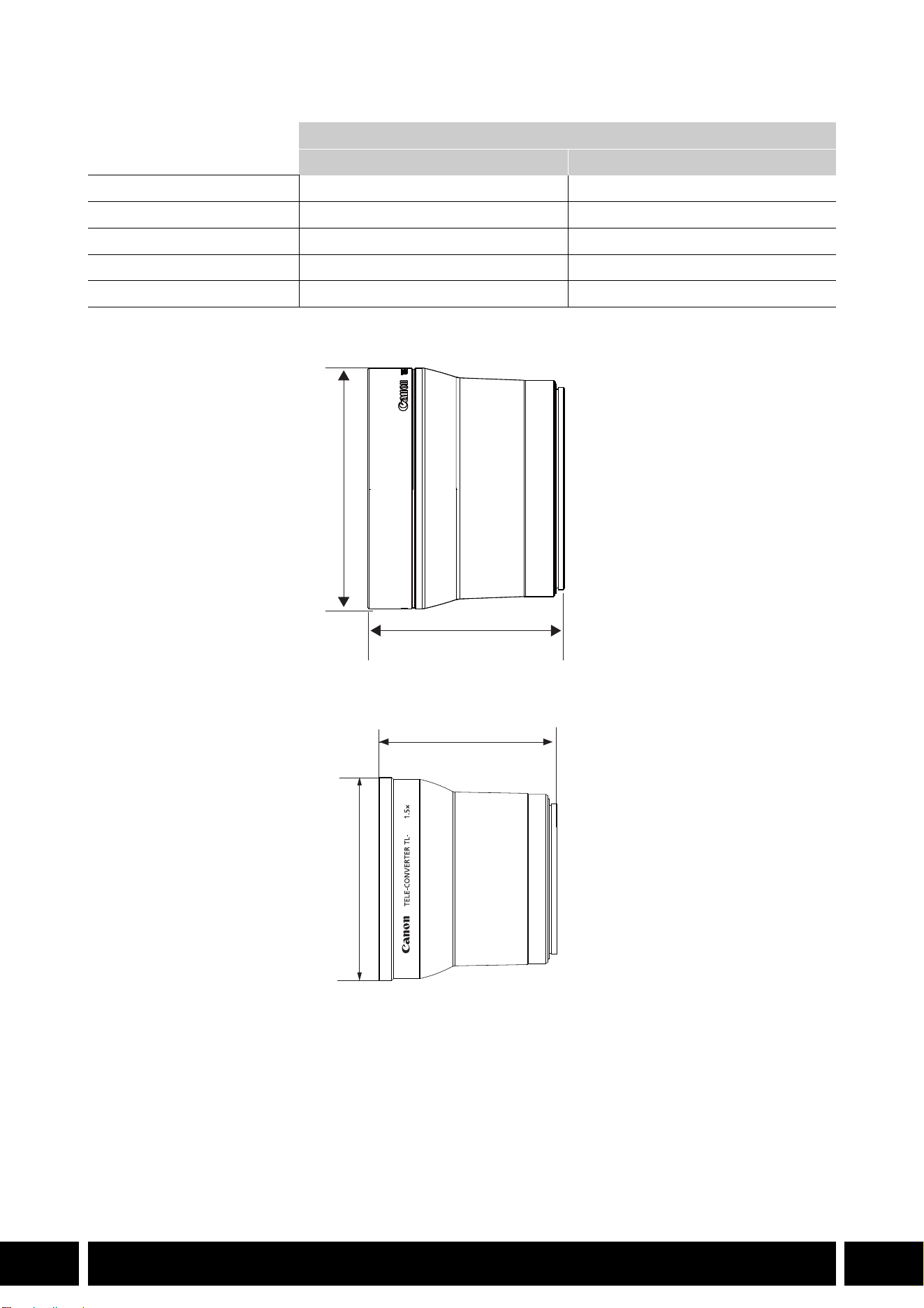
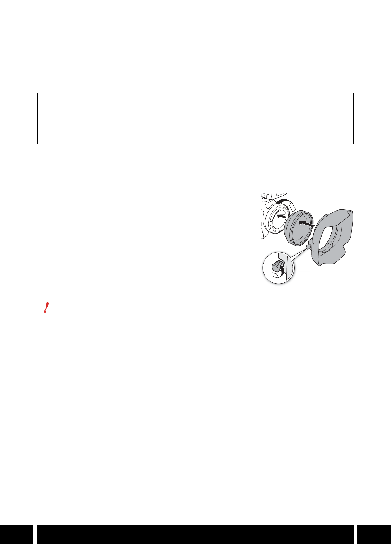
新增功能和镜头兼容性
9
ZH
WA-H58/WA-U58 广角辅助镜头
使用 WA-H58/WA-U58广角辅助镜头能够以更广的视角记录影片、拍摄照片。根据摄影机的不同,
影像稳定方法和最小的被摄体距离可能会更改。有关各个功能的详情,请参阅所用摄影机的使用说
明书。
将广角辅助镜头安装到摄影机
本节说明如何将广角辅助镜头安装到摄影机,以 WA-U58 为例。可以按照相同的步骤安装 WA-H58 。
1. 卸下摄影机随附的镜头遮光罩,然后将广角辅助镜头完全旋入
镜头滤镜螺纹中 (햲)。
2. 将广角辅助镜头随附的遮光罩安装到广角辅助镜头的前方,然
后拧紧螺钉 (햳)。
• 请笔直安装遮光罩,注意不要让其弯曲。如果遮光罩弯曲变
形,则其阴影可能会出现在画面中。
随附的附件
软袋
镜头盖
防尘罩
遮光罩
• 如果使用了广角辅助镜头,则图像外围可能会出现畸变。
• 其他滤镜和摄影机的遮光罩不能与广角辅助镜头同时使用。
• 使用前请清洁广角辅助镜头和摄影机的镜头表面。否则,摄影机可能会对镜头表面的灰尘
或其他污物进行错误对焦。
• 使用广角辅助镜头可能会影响前摄影指示灯 *,减小无线遥控器的有效作用范围,或在使用
选购的摄影灯 * 记录时导致阴影出现。
* 并非所有摄影机型号均配备摄影指示灯或均兼容选购的摄影灯。
• 使用广角辅助镜头时需小心,避免弄脏或留下指纹印。
• 存放广角辅助镜头时,务必装上镜头盖。
• 请勿将广角辅助镜头存放在潮湿的地方。否则,可能会发霉。
• 调整白平衡时,建议先把广角辅助镜头安装至摄影机,然后再调整白平衡。
햲
햳
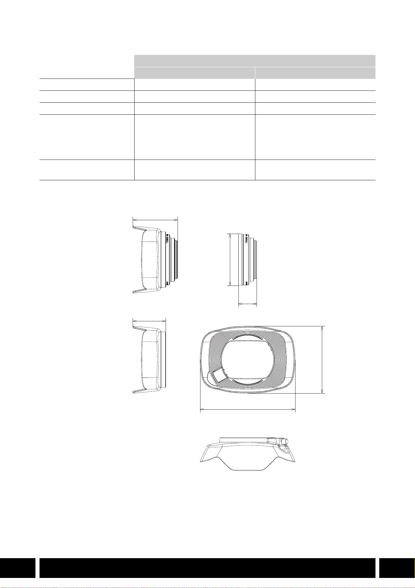
新增功能和镜头兼容性
10
ZH
规格
WA-H58尺寸详情
广角辅助镜头
WA-H58 WA-U58
倍率 约 0.75倍约0.8倍
镜头结构 2组 2片 2组 2片
滤镜直径
58 mm 58 mm
尺寸 ∅ 79 × 28 mm (长度 )
(不含遮光罩 )
144 × 102 × 68 mm
(宽 ×高 ×深 )
(含随附的遮光罩 )
∅ 85 × 33 mm (长度 )
(不含遮光罩 )
150 × 106 × 72 mm
(宽 ×高 ×深 )
(含随附的遮光罩 )
重量 260 g (不含遮光罩 )
310 g (含随附的遮光罩 )
325 g (不含遮光罩 )
380 g (含随附的遮光罩 )
mm
∅ 79
68
28
144
102
50
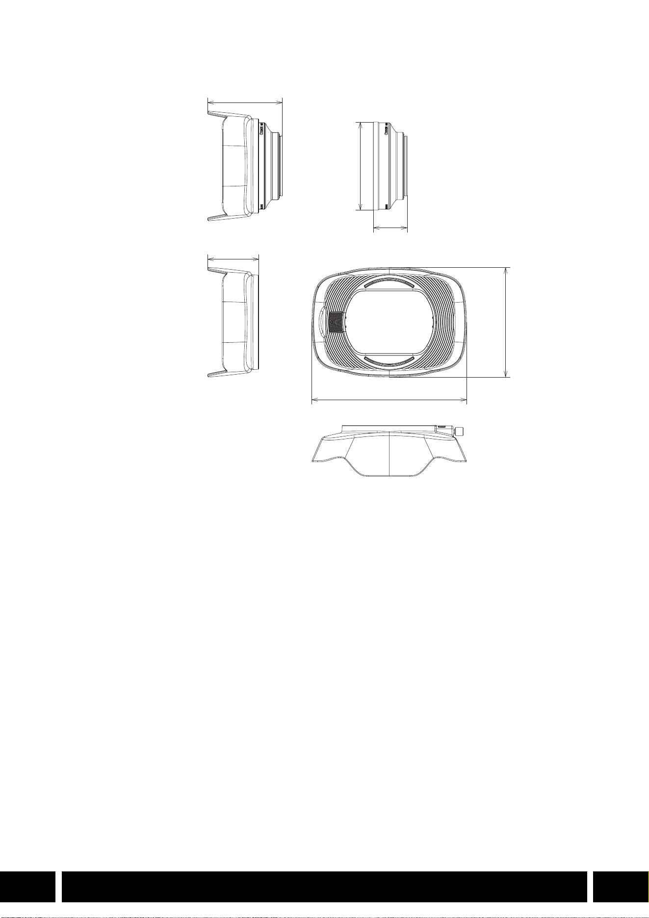
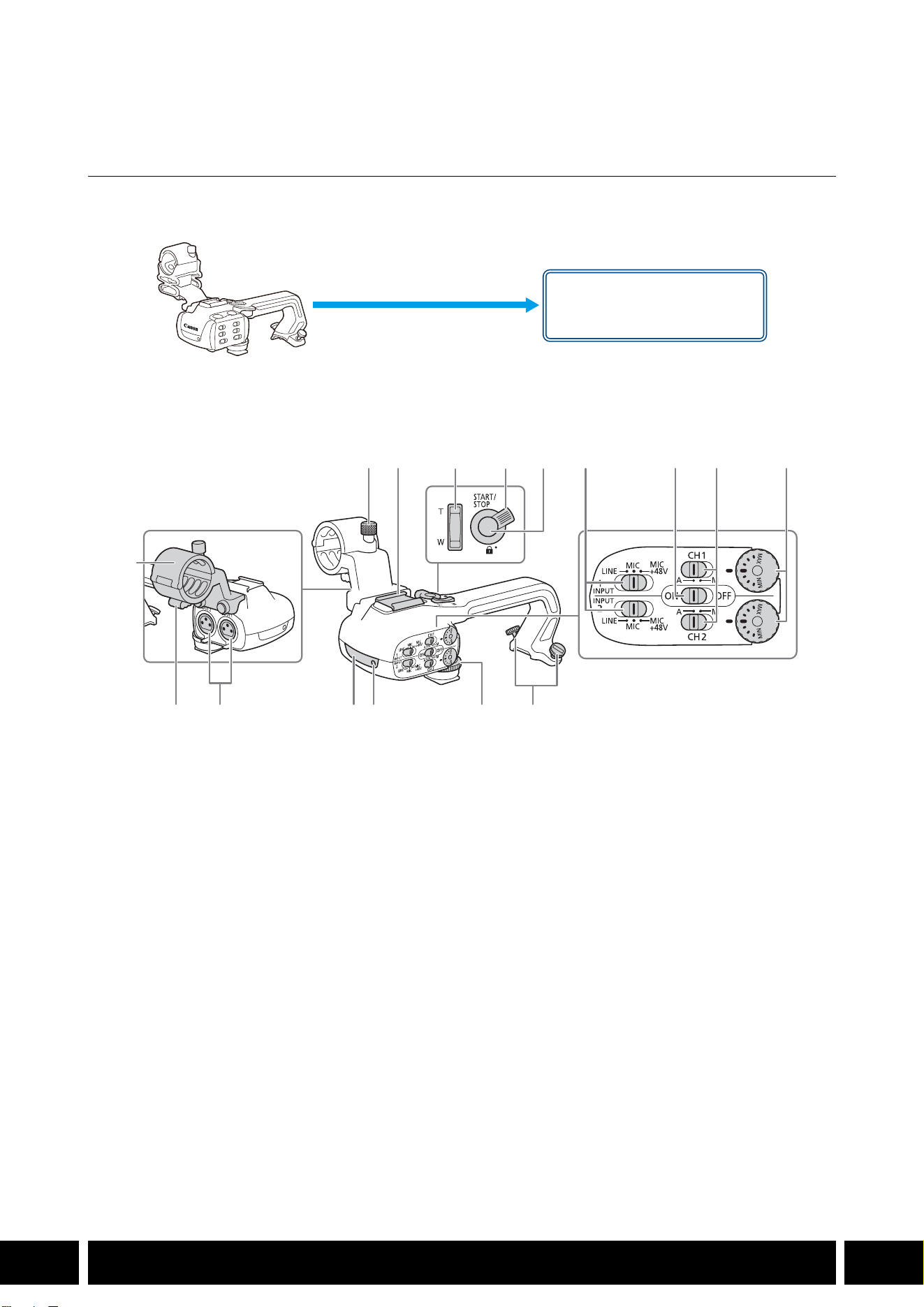
拍摄风格和配置
12
ZH
拍摄风格和配置
HDU-1/HDU-3 手柄
将手柄连接到摄影机后,可以使用 INPUT端子、红外光和摄影指示灯。
有关安装和使用手柄的方法,请参阅所用摄影机的使用说明书。
部件名称
HDU-1
1 麦克风卡座单元
2 麦克风锁定螺丝
3 附件冷靴
4 手柄变焦杆
5START/STOP锁定 (C)杆
6START/STOP按钮
7 INPUT 1和 INPUT 2的灵敏度选择开关
8 INPUT 端子 ON/OFF 开关
9CH1和 CH2的音频电平开关
10 CH1和 CH2的音频电平转盘
11 麦克风连接线夹
12 INPUT 1和 INPUT 2端子
13 红外光
14 摄影指示灯
15 手柄前端螺丝
16 手柄后端螺丝
手柄卡口
(直接安装 )
23 7 8 9 10
161514131211
1
456
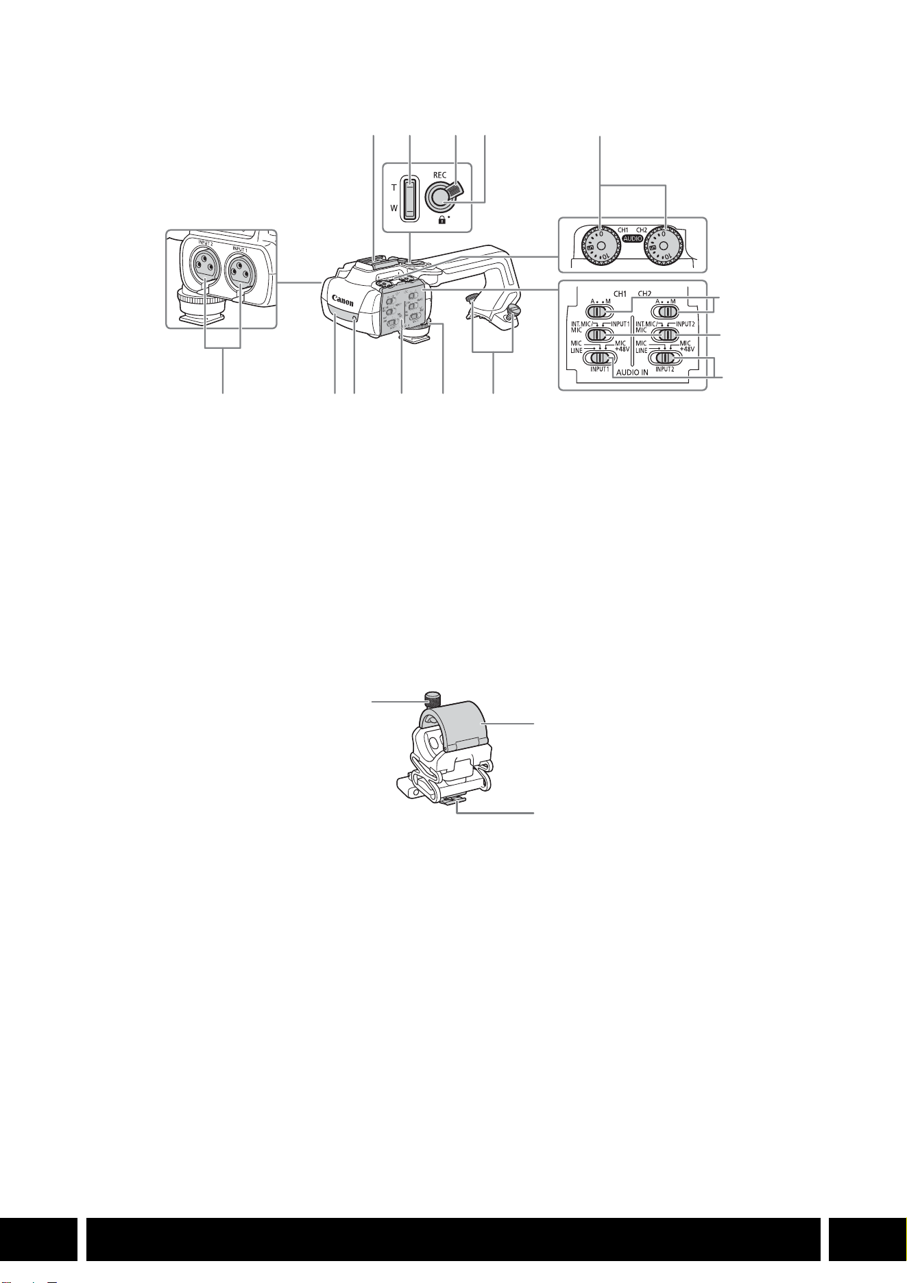
拍摄风格和配置
13
ZH
HDU-3
麦克风卡座单元 (HDU-3随附 )
1 冷靴
2 手柄变焦杆
3REC按钮锁定 (C)杆
4REC (开始 /停止记录视频 )按钮
5 音频电平转盘:CH1 ( 左 )和 CH2 (右 )
6 音频电平开关:CH1 ( 左 )和 CH2 (右 )
7 AUDIO IN开关 (音频输入选择 ):CH1 (左 )
和 CH2 (右 )
8 INPUT 1 (左 )/INPUT 2 (右 )开关
(音频源选择 )
9 INPUT端子:INPUT 1 (右 )、 INPUT 2 (左 )
10 红外光
11 摄影指示灯
12 音频控件盖
13 手柄前端螺丝
14 手柄后端螺丝
1 麦克风锁定螺丝
2 麦克风卡座
3 麦克风连接线夹
1
7
8
91011121314
234
5
6
1
2
3