MAC 2000 Wash XB Upgrade Kit Installation Guide – Page 1 of 30
MAC 2000 Wash XB Upgrade Kit
Installation Guide
Introduction
This Installation Guide explains how to install the MAC 2000 Wash XB Upgrade Kit to convert a standard
MAC 2000 Wash to an XB model that uses a 1500 watt Osram HTI 1500 W/D7/60 SharXS lamp.
The MAC 2000 Wash XB Upgrade Kit has part number P/N 91310980.
For the latest documentation and information about this and all Martin Professional products, please visit
the Martin website at www.martin.com.
Martin has a buy-back offer for electronic ballasts from MAC 2000 Wash fixtures that are upgraded to XB
models. Please do not send ballasts to Martin without following the correct procedure for the buy-back
scheme. If you have Login rights to the Support area at www.martin.com you can see details there.
Otherwise please contact your Martin distributor for details.
Installation of the upgrade kit consists of two sequences of operations: replacement of components in the
base, and replacement of components in the head.
Warning! Read and follow the safety precautions in the MAC 2000 Wash XB user manual before installing
the MAC 2000 Wash XB Upgrade Kit. The user manual is supplied with the Upgrade Kit and is
also available for download from www.martin.com
Disconnect the fixture from power, allow to cool and place on a workbench before starting work.
The MAC 2000 Wash XB Upgrade Kit must be installed by qualified professional technicians only.
Read all of this Installation Guide carefully before starting to install the Upgrade Kit. Martin
Professional A/S and its affiliated companies cannot be held responsible for any injury, damage,
direct or indirect loss, consequential or economic loss or any other loss resulting from failure to
follow the instructions, respect the safety precautions and carry out the safety tests listed in this
Installation Guide.
If you have any questions about how to install the Upgrade Kit or use the MAC 2000 Wash XB
safely, please contact your local Martin distributor (see www.martin.com/distributors for details)
or call the Martin 24-hour service hotline on +45 8740 0000, or in the USA on 1-888-tech-180.
Important!To avoid damage to PCBs and their sensitive electronic components, take precautions to avoid
ESD (electrostatic discharge) and carry out work at an ESD-free workstation. Do not get oil or
grease onto optical components. If necessary, clean components with 99.9% isopropyl alcohol.
© 2008 Martin Professional A/S. Olof Palmes Allé 18, DK-8200 Aarhus N, Denmark. Information subject to change without notice. Martin
Professional A/S and all affiliated companies disclaim liability for any injury, damage, direct or indirect loss, consequential or economic
loss or any other loss occasioned by the use of, inability to use or reliance on the information contained in this installation note. The
Martin logo, the Martin name and all other trademarks in this document pertaining to services or products by Martin Professional A/S or its
affiliates and subsidiaries are trademarks owned or licensed by Martin Professional A/S or its affiliates or subsidiaries.
P/N 35000600 Rev. B (for use with wireset v.2)
MAC 2000 Wash XB Upgrade Kit Installation Guide – Page 2 of 30
Overview
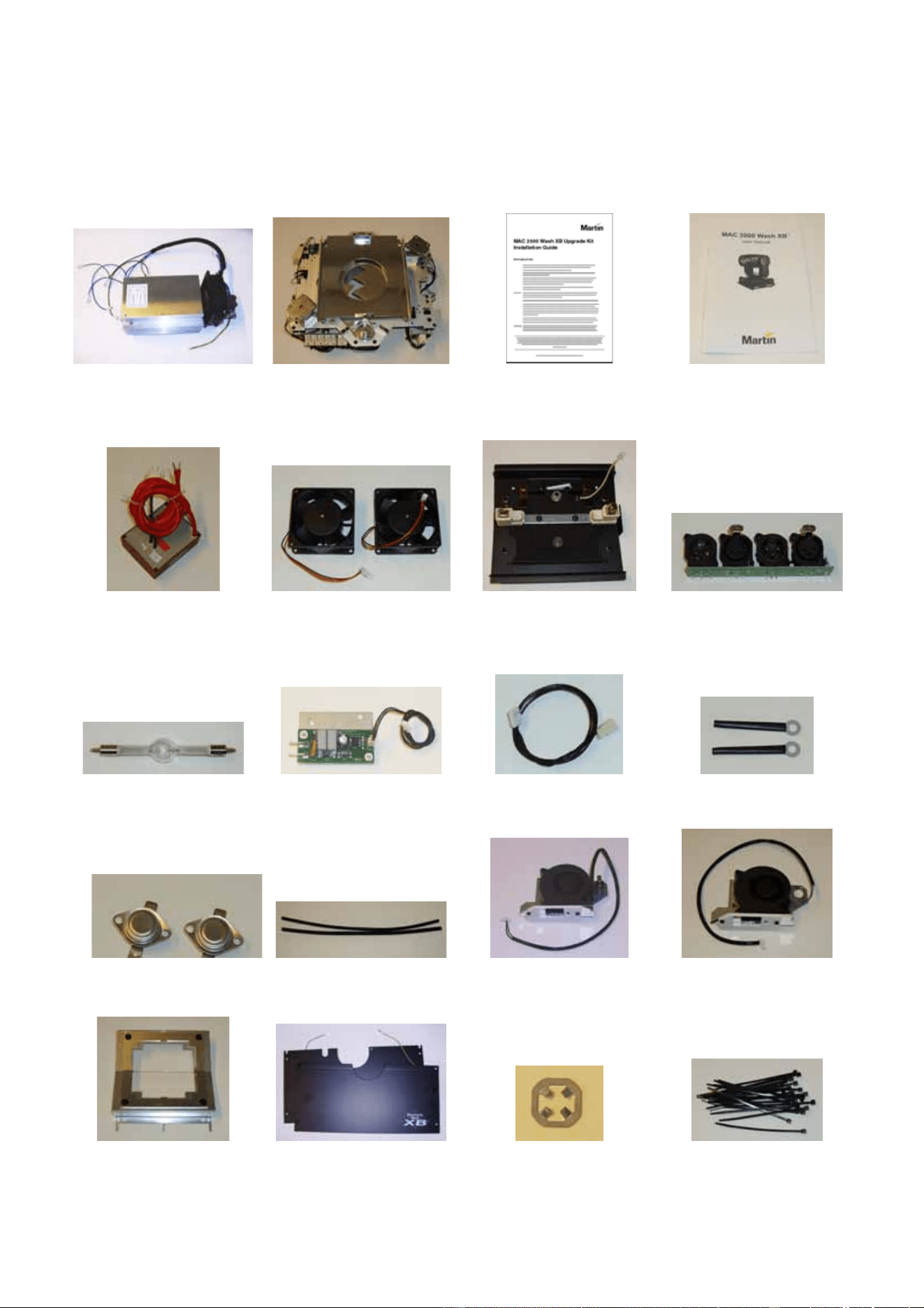
The MAC 2000 Wash XB Upgrade Kit contains the following items:
ABCD
EFGH
IJKL
MNOP
QRST
Table 1
MAC 2000 Wash XB Upgrade Kit Installation Guide – Page 3 of 30
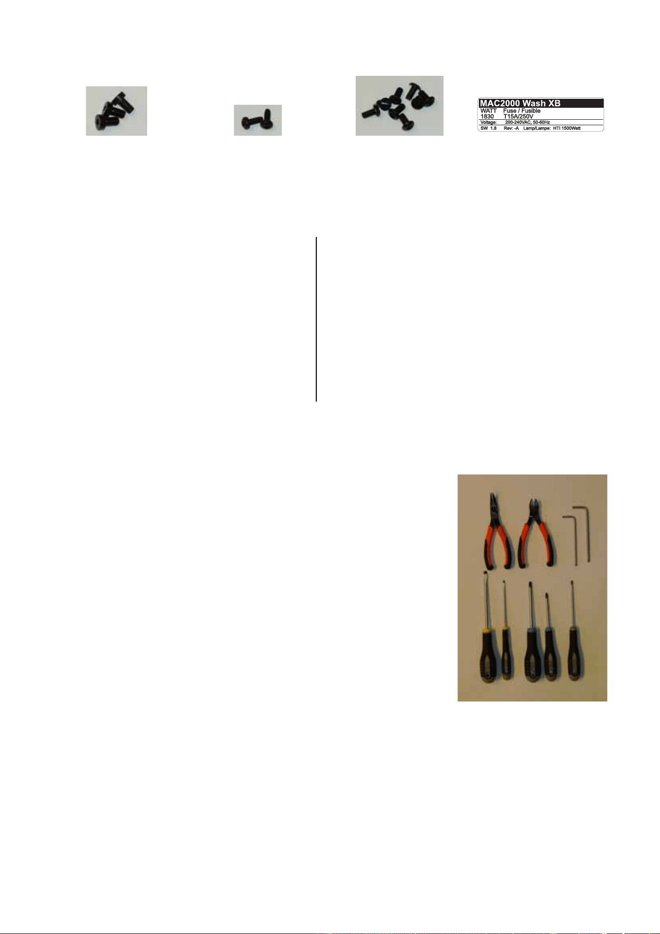
Tools required
All screw sizes given in this Installation Guide are indicative only.
The following tools are normally required to upgrade a standard MAC
2000 Wash to an XB model. However, if screws have been replaced
during service, for example, you may find that other tools are
required.
• needle-nose pliers
• wire cutters
• 4 mm and 5 mm Allen keys
• 2 x flathead screwdrivers
• Pozidriv PZ1 and PZ2 screwdrivers (all cross-head screws in
MAC 2000 Wash fixtures are Pozidriv, not plain Phillips type)
• Torx TX20 screwdriver
To help you avoid dropping screws into the fixture, we recommend
that you magnetize tools so that screws cling to them.
UVWX
Table 1
A Electronic ballast module P/N 55205560
B CMY+C and dimmer module P/N 55205110
C This instruction note P/N 35000600
D MAC 2000 Wash XB user manual P/N 35000219
E Ignitor (starter) with plug P/N 62228025
F 12 VDC 3” high-speed fan (x2) P/N 62222079
G Lamp housing rear cover module P/N 55205111
H Data connections panel P/N 62004554
I Osram HTI 1500W/D7/60 lamp P/N 97010322
J Remote lamp on/off opto-switch P/N 55205580
K Reduced lamp power (dimmer) circuit
leads (main PCB to ballast), 640 mm P/N 11730006
L Wire retainer, flexible, 4 mm (x2) P/N 13101010
M Thermoswitch, fixed bracket (x2) P/N 05040023
N Heat-shield sleeve 340 mm (x2) P/N 62400444
O Lamp fan/thermoswitch assembly, R P/N 62406058
P Lamp fan assembly, L P/N 62406064
Q Heat filter module P/N 62323015
R Base lid A with ground lead P/N 55205504
R Base lid B with ground lead P/N 55205505
S Lamp wire clamp plate retainer P/N 08074402
T High-temperature cable tie (x25) P/N 13104000
U M6x10 ch. allen bolt low black (x3) P/N 08111201
V M4x10 Torx self-tapping screw (x2) P/N 08070701
W M4x12 bh. Torx screw black (x8) P/N 08070710
X Replacement product label P/N 33190032
Parts list
MAC 2000 Wash XB Upgrade Kit Installation Guide – Page 4 of 30
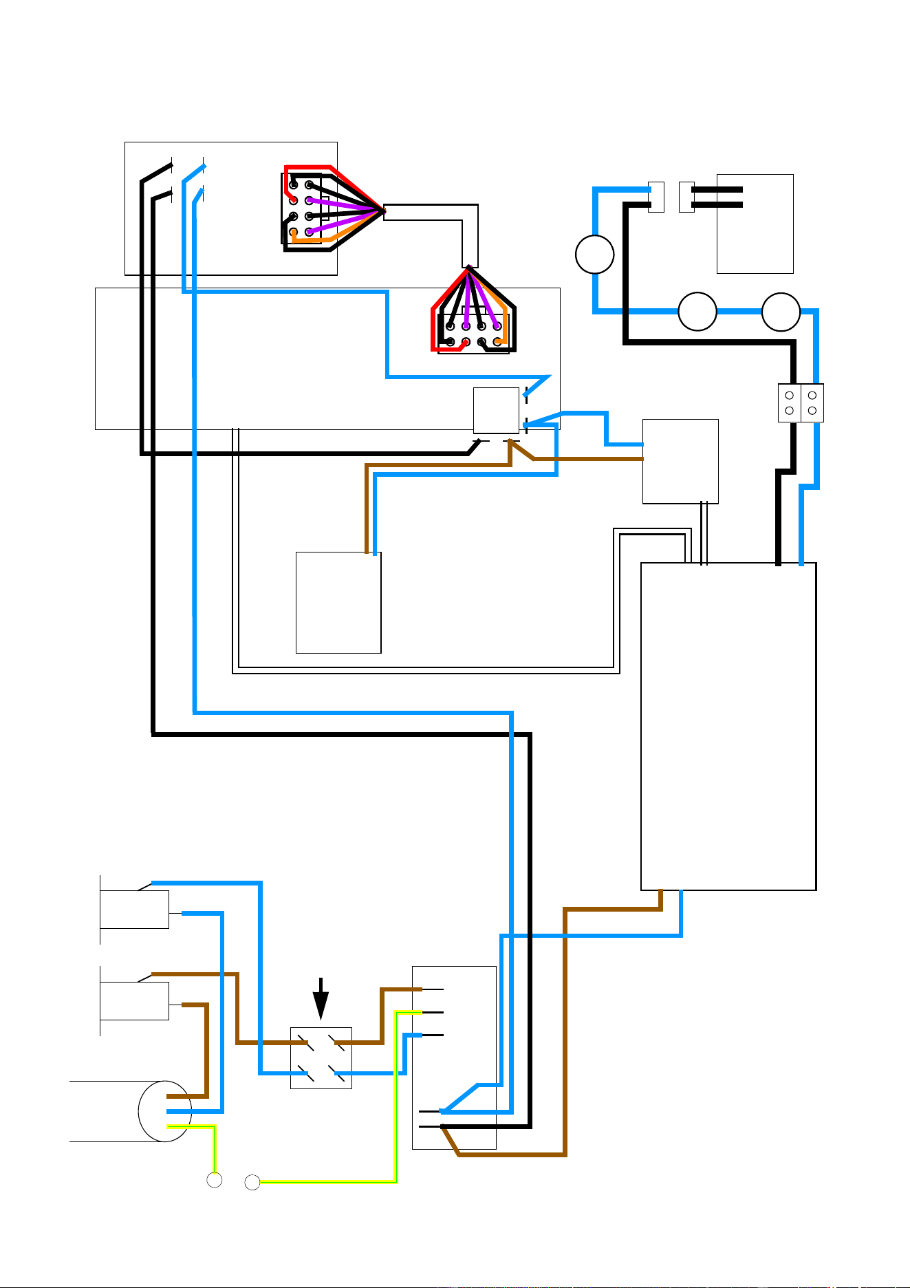
Schematic wiring diagram
Mains cable
230 VAC
Power on/off switch
Mains filter
Main PCB
SMPS PCB
Ignitor
(starter)
on/off
relay
Remote
opto-switch
Reduced lamp power (dimmer) circuit
Electronic ballast
Fuse Fuse
lamp on/off
ballast fan
thermoswitch
t
h
e
r
m
o
s
w
i
t
c
h
t
h
er
m
o
s
w
i
t
ch
Lamp
L
N
Wireset version 2, P/N 11850226-A
MAC 2000 Wash XB Upgrade Kit Installation Guide – Page 5 of 30
Replacement of components in the base
To install the MAC 2000 Wash XB Upgrade Kit base components in a standard MAC 2000 Wash fixture:
1. Disconnect the fixture from
power, allow to cool, and place
on a workbench. Take
precautions against ESD
(electro-static discharge).
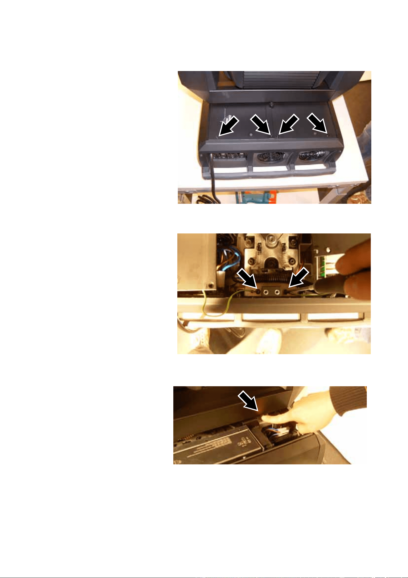
2. See Figure 1. Remove the four
screws from the corners of
each base cover (8 screws
total, PZ2, P/N 08070502).
Keep the screws for re-use
during reassembly.
3. See Figure 2. Slide the covers
out slightly for access to the
ground (earth) leads.
Disconnect the ground leads
by removing their screws
(arrowed, Torx 20, P/N
08070701) and remove the
covers. Keep the screws. The
covers are no longer required
as new items are supplied in
the Upgrade Kit.
4. Use the pan lock (arrowed in
Figure 3) and tilt lock to
immobilize the head.
Figure 1
Figure 2
Figure 3
MAC 2000 Wash XB Upgrade Kit Installation Guide – Page 6 of 30
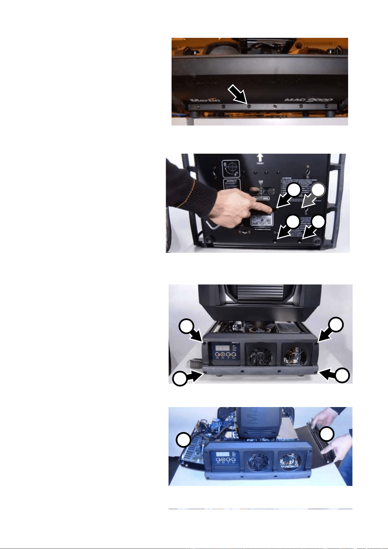
5. Lay the fixture down carefully
on its side and remove the
screw third from the left
(arrowed, Torx 20, P/N
08190404) from the bottom of
the base on the ballast side.
Keep the screw for re-use
during installation.
6. See Figure 5. Use a 4 mm
Allen key to remove the three
ballast mounting screws A
from their holes (arrowed)
around the serial number label
in the base. In older fixtures,
you must also remove a fourth
ballast mounting screw B.
Throw these screws away
because three new ballast
mounting screws are provided
in the Upgrade Kit. When you
install the new ballast, you will
insert the new mounting
screws in the holes at A.
7. See Figure 6. Stand the fixture
up again. Remove the four
Allen screws (P/N 08111206)
A from the top corners of the
base panels on both sides of
the fixture. Remove the two
Allen screws (P/N 08111210)
B from the bottom corners of
the base panels on the ballast
side of the fixture and remove
the ballast side base cover B
completely. Keep the side
cover and all screws for
re-use.
8. See Figure 7. Loosen the
Allen screws (P/N 08111210)
C in the bottom corners of
the base panels on the main
PCB side of the fixture and
swing the main PCB side
base cover A open.
Figure 4
Figure 5
A A
A B
Figure 6
A
A
C
B
Figure 7
A
B
MAC 2000 Wash XB Upgrade Kit Installation Guide – Page 7 of 30
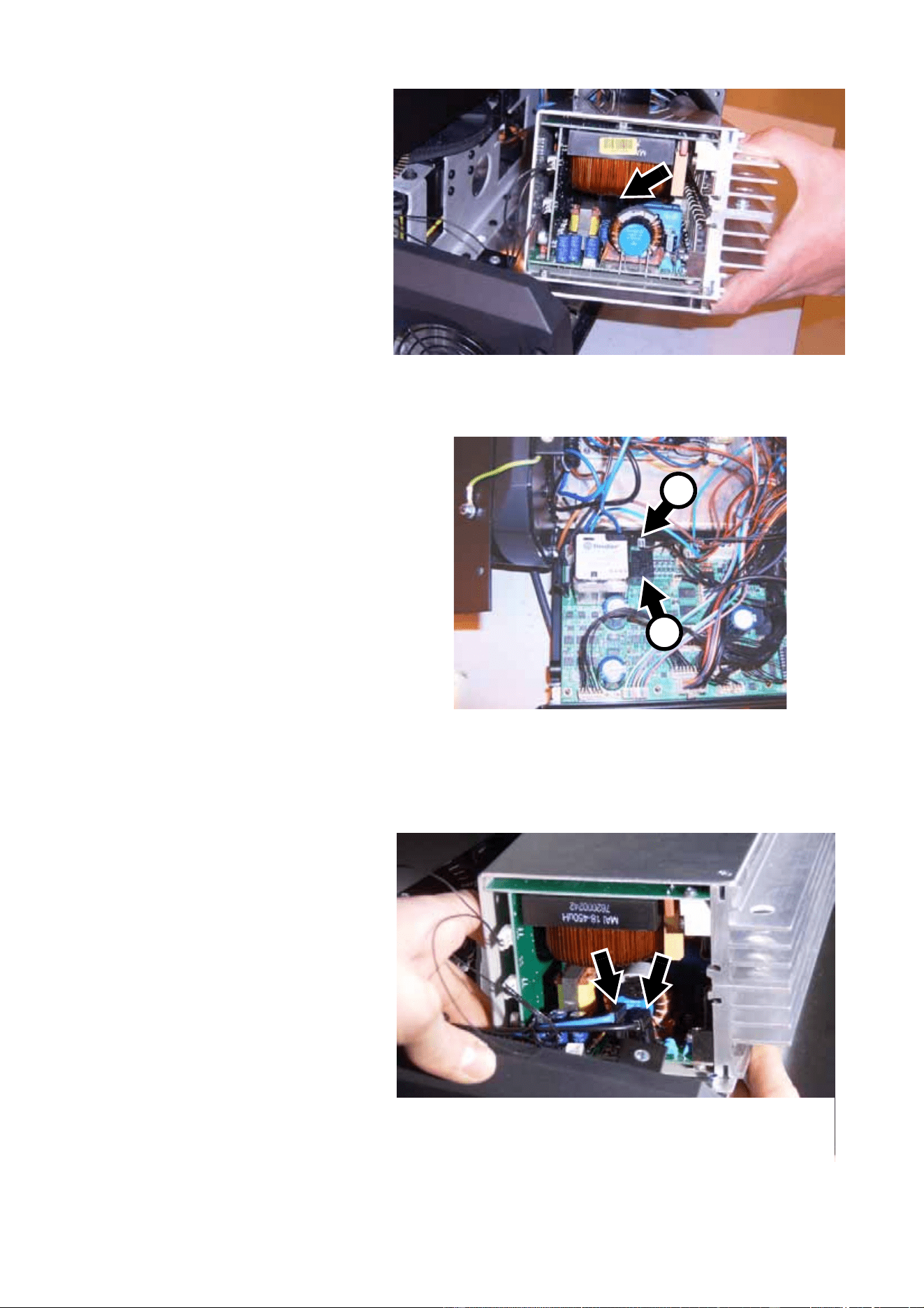
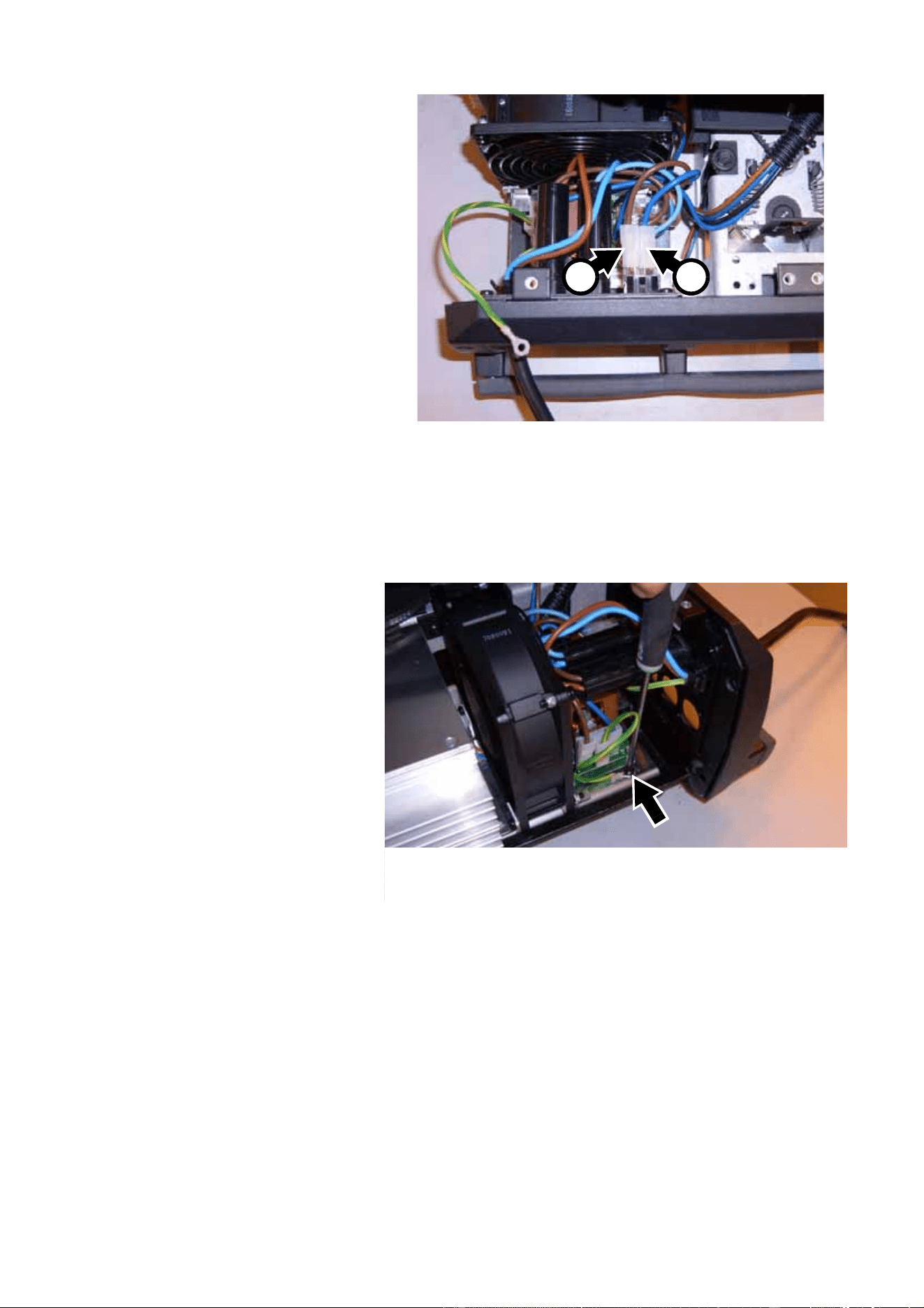
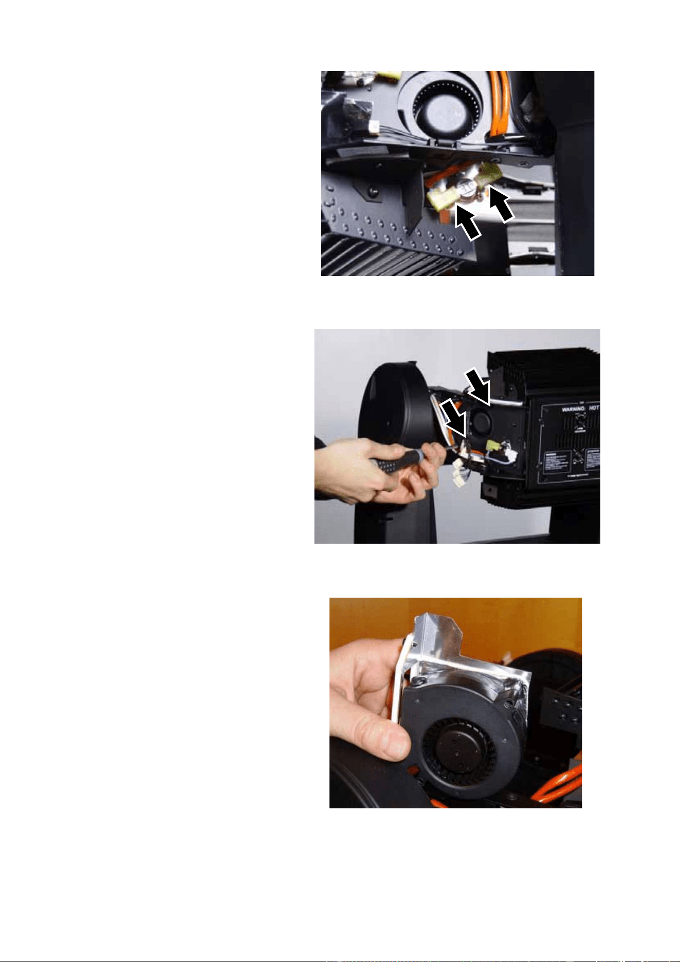
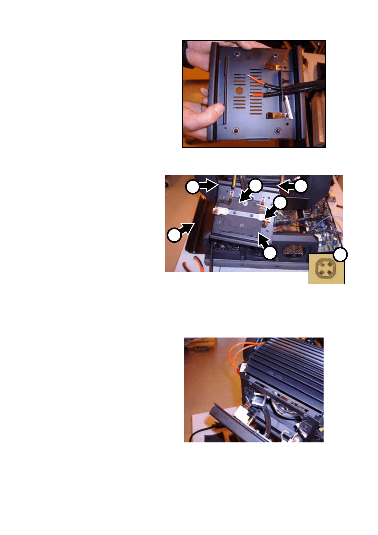
9. See Figure 8. Lift the ballast
up slightly and disconnect
the two ignitor leads (one
blue, one black) from their
spade connectors A. Then
disconnect the reduced lamp
power (dimmer) circuit
connector from connector
X200 B.
NB: Figure 8 shows the
ballast completely removed
from the fixture to make it
easier to see the connectors.
10. See Figure 9. Cut cable ties if
necessary and disconnect
the mains power leads from
PL1, PL2 and PL3 on the
mains filter PCB (arrowed)
that is part of the ballast
assembly.
11. See Figure 10. Unlock the
pan lock and swing the head
around for access, then use
a wire-cutter to cut the cable
ties and release the ballast
wiring harness (arrowed) that
runs from the ballast to the
main PCB.
Figure 8
A
A
B
Figure 9
Figure 10
MAC 2000 Wash XB Upgrade Kit Installation Guide – Page 8 of 30
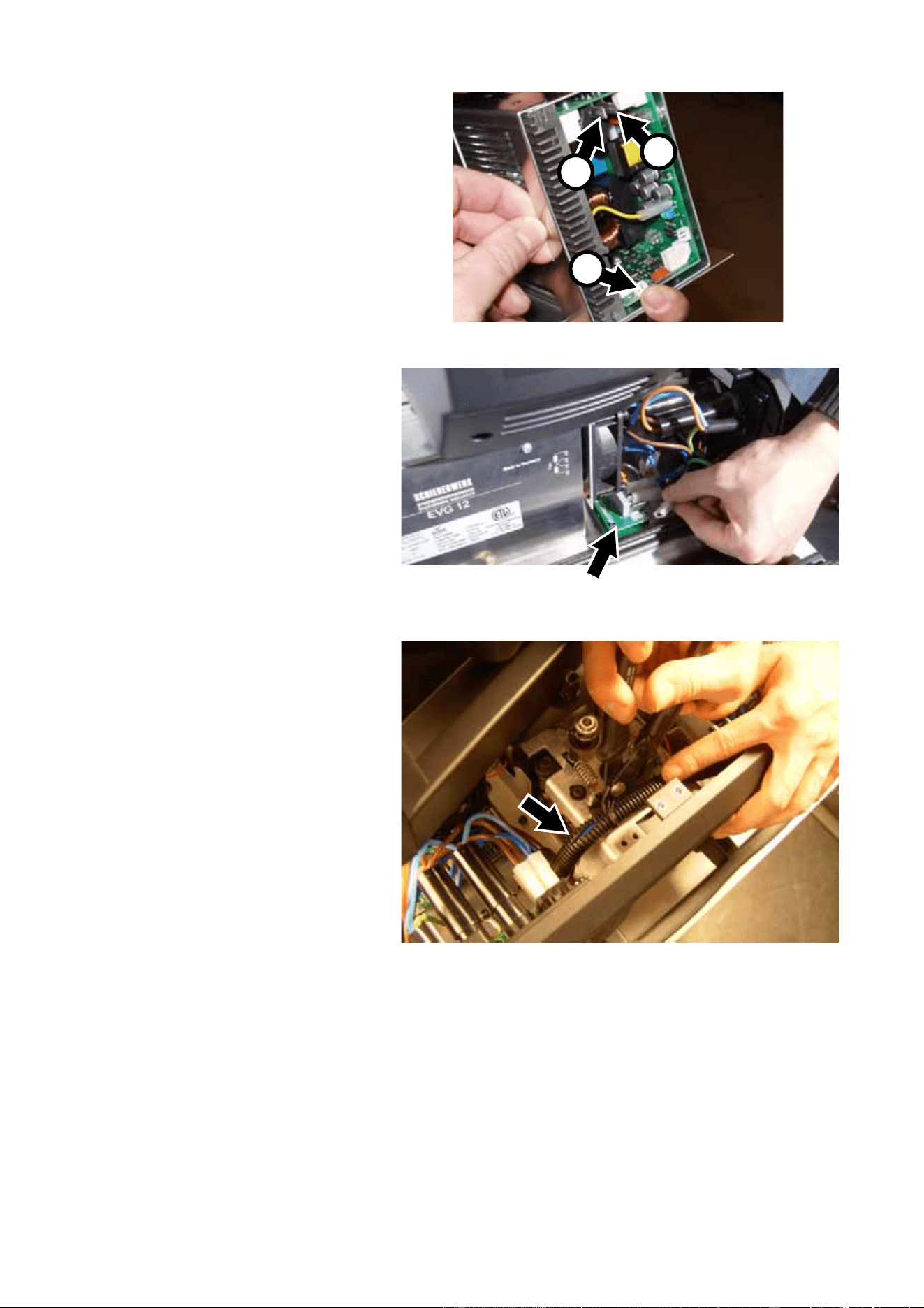
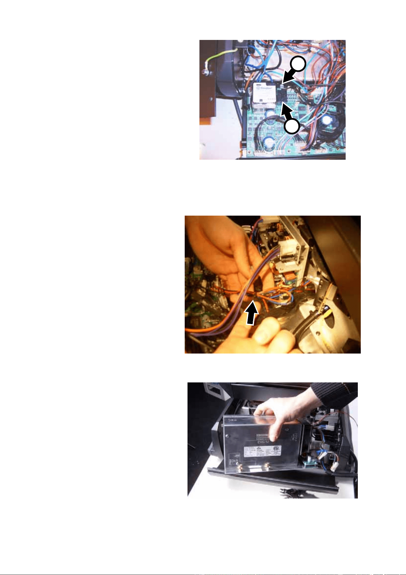
12. See Figure 11. Disconnect
the thick blue and brown
leads (arrowed) from the
SMPS (switch-mode power
supply).
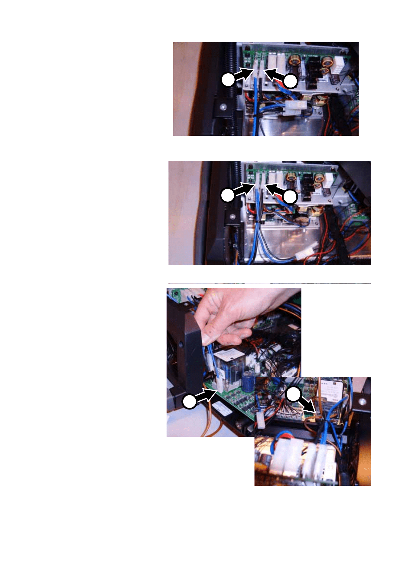
13. See Figure 12. Disconnect
the 2 blue leads, the black
lead and the brown lead from
connectors J4, J5, J6 and J8
(arrowed) around the lamp
on/off relay on the main PCB.
14. See Figure 13. Disconnect
the low-voltage ballast fan
connector (arrowed) from
connector PL58 (F7) on the
main PCB.
The new ballast has a 230 V
cooling fan, so the
low-voltage ballast fan
connector at PL58 on the
main PCB will no longer be
used when you install new
components.
Figure 11
Figure 12
Figure 13
MAC 2000 Wash XB Upgrade Kit Installation Guide – Page 9 of 30
15. See Figure 14. Disconnect
the reduced lamp power
(dimmer) circuit connector A
from connector PL49 behind
the reduced lamp power
relay B on the main PCB.
16. See Figure 15. Cut the cable
tie (arrowed) on the ballast
fan leads.
17. See Figure 16. Lift the ballast
out of the base of the fixture
and set aside for possible
return to Martin under the
buy-back scheme (see
“Introduction” on page 1).
Figure 14
A
B
Figure 15
Figure 16
MAC 2000 Wash XB Upgrade Kit Installation Guide – Page 10 of 30
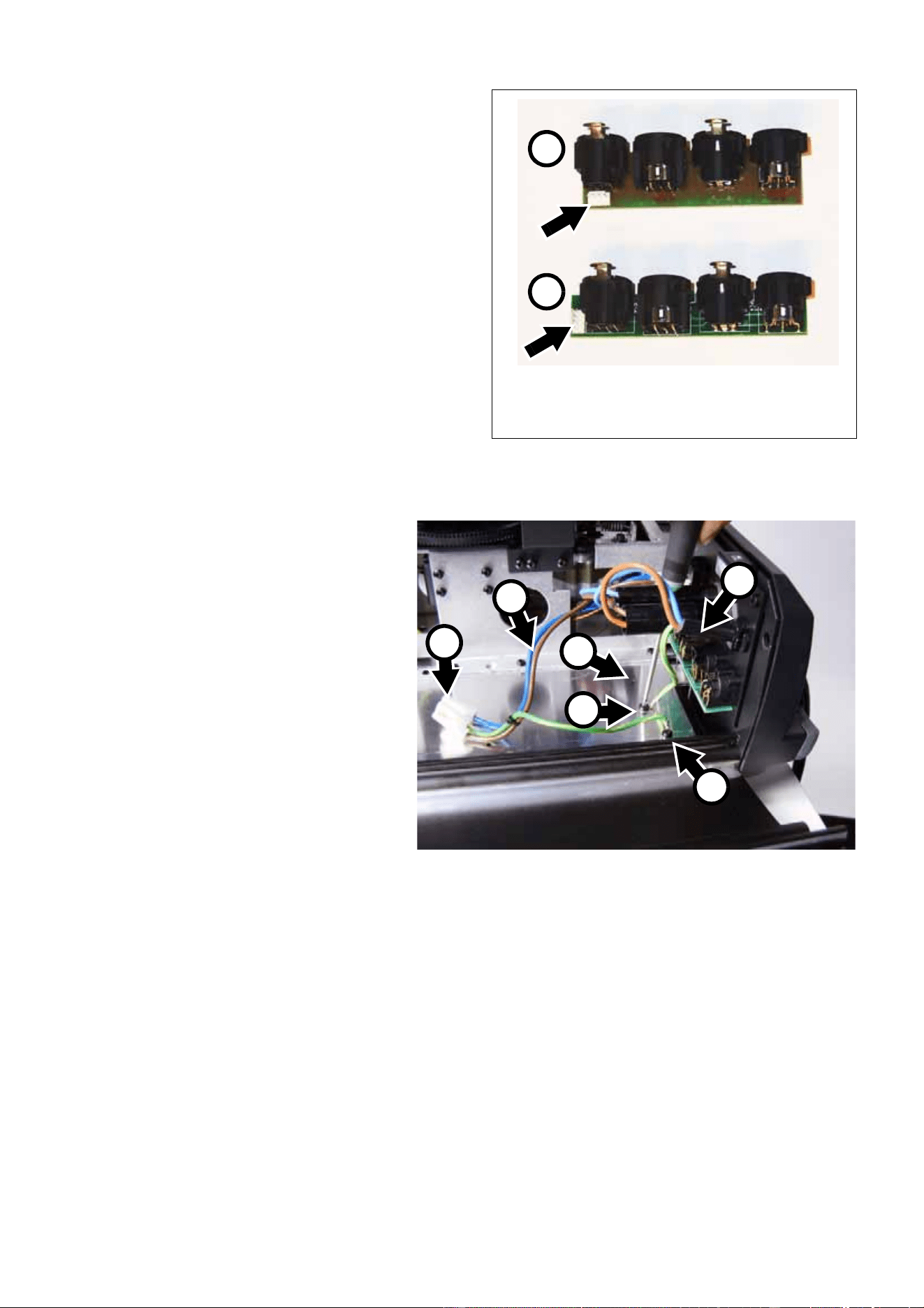
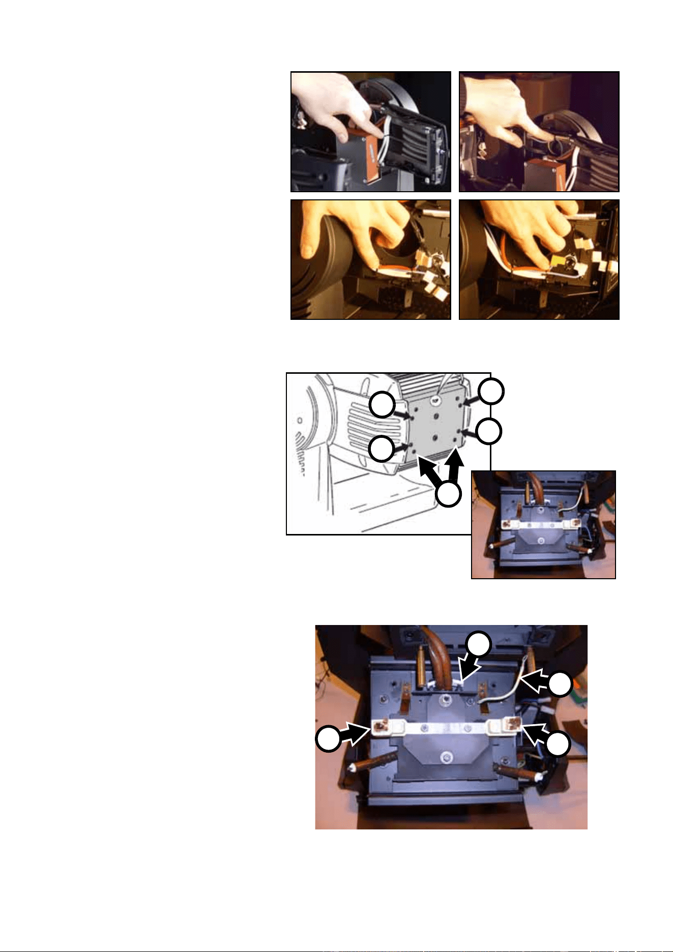
18. See Figure 17. Two types of XLR connector
modules have been fitted to the MAC 2000
Wash. If your fixture has the wider type
module A with the 4-pin connector (arrowed)
behind the XLR sockets, there will not be
enough space to install the new ballast so
you must replace the module with the
narrower type B with the 4-pin connector
(arrowed) in line with the sockets at the end
of the PCB. A module type B is supplied in
the Upgrade Kit (P/N 62004554, see “H” in
Table 1). If the narrower type module B is
already installed, just keep the module
supplied in the Upgrade Kit as a spare.
To replace the XLR module, unplug the
module at its 4-pin connector, unscrew the 8
screws (PZ1, P/N 08200102) around the
XLR sockets on the connections plate and lift
the module out of the fixture. Install the new
XLR module supplied with the Upgrade Kit re-using the 8 screws, and connect the plug to the new
module’s 4-pin connector.
19. See Figure 18. You must now
relocate the mains input
cable ground (earth) lead to
make space for the new
ballast. First, strip some of
the outer insulation from the
mains cable at A.
20. See Figure 18. Unscrew the
Torx 20 screw B (P/N
08070701) that fastens the
lead to the metal base plate.
Throw this screw away. Move
the mains input cable ground
lead to the existing hole C in
the base plate and fasten it to
the base plate with one of the
new Torx 20 screws,
P/N 08070701, supplied in
the Upgrade Kit (see “V” in
Table 1). To make sure the
lead does not foul the new
ballast, fasten the screw with
the lead trailing out towards
the fixture’s XLR connectors.
Remove screw D from the mains filter ground lead. This screw is no longer required. Disconnect the
blue and brown leads E from the fixture’s power on/off switch, and remove the ground lead and blue
and brown leads with their connector F. These leads are no longer required. New leads are supplied
installed on the mains filter on the new ballast assembly.
Warning! For safety reasons, the two ground (earth) leads – one from the fixture’s mains input cable and
one from the mains filter on the ballast assembly – shown at B and D in Figure 18 MUST be
fastened to the base plate separately with two separate screws when the new ballast assembly is
installed. DO NOT take a short-cut and use one single screw to fasten these two ground leads to
the base plate together, or you will create a safety risk, void the product warranty and make the
product illegal.
Figure 17
A
B
Figure 18
B
C
A
F
D
E
MAC 2000 Wash XB Upgrade Kit Installation Guide – Page 11 of 30
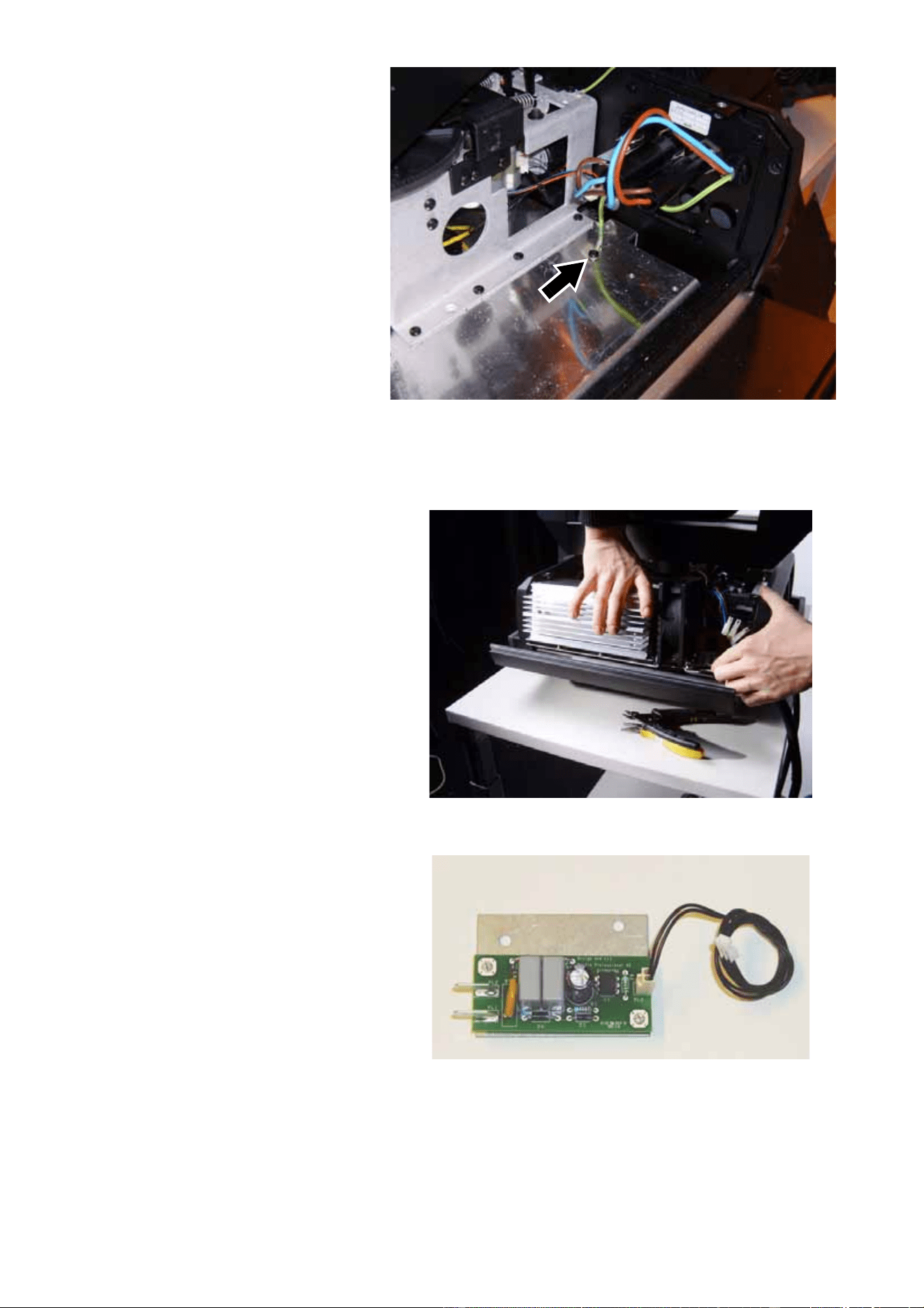
21. When you have completed
step 20. the fixture should
look as shown in Figure 19
with the relocated mains
input cable ground lead
(arrowed) fastened to the
base plate and trailing back
towards the XLR connectors.
22. See Figure 20. Place the new
ballast loosely in the base
and check that it will not foul
any wiring or other
component when installed.
Adjust wiring or components
if necessary, Do not fasten
the ballast to the fixture yet
because you must make
electrical connections first.
23. See Figure 21. An
opto-switch for the remote
lamp on/off circuit is supplied
with the Upgrade Kit (see “J”
in Table 1).
Figure 19
Figure 20
Figure 21
MAC 2000 Wash XB Upgrade Kit Installation Guide – Page 12 of 30
24. See Figure 22. Remove the
two Torx 20 screws
(P/N 08070701) arrowed
from the chassis facing the
main PCB, noting that a
ground (earth) lead is
fastened to one of the
screws.
25. See Figure 23. Fasten the
remote lamp on/off
opto-switch A to the base as
shown, re-using the original 2
screws and re-installing the
ground lead on the screw
where it was originally
located. A pair of leads with
connectors is supplied
installed on the remote lamp
on/off opto-switch. Both
connectors are marked LA.
See Figure 23. One
connector is installed at B on
the remote lamp on/off
opto-switch PCB. Route the
two leads alongside the
ballast wiring harness C over
to the ballast
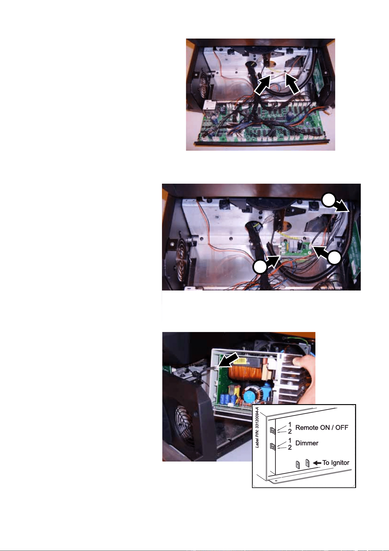
26. See Figure 24. A jumper will
normally be fitted on the upper
low-voltage multi-connector
X301 (arrowed) on the ballast
PCB. Remove the jumper and
connect the pair of leads from
the remote lamp on/off
opto-switch to connector X301
as shown in Figure 24.
Figure 22
C
A
Figure 23
B
Figure 24
MAC 2000 Wash XB Upgrade Kit Installation Guide – Page 13 of 30
27. See Figure 25. Connect the
reduced lamp power
(dimmer) circuit leads
supplied with the Upgrade Kit
(P/N 11730006, see “K” in
Table 1) to the lower
low-voltage multi-connector
X200 (arrowed) on the ballast
PCB.
28. See Figure 26. Route the
reduced lamp power
(dimmer) circuit leads
alongside the ballast wiring
harness over to the main
PCB and plug them into
connector PL49 A behind the
reduced lamp power relay B
on the main PCB.
29. See Figure 27. Connect the
blue lead and black lead from
the ignitor (starter) to the
spade connectors (arrowed) in
the base of the new ballast.
Polarity is not important – the
blue and black leads are
interchangeable.
Figure 25
Figure 26
A
B
Figure 27
MAC 2000 Wash XB Upgrade Kit Installation Guide – Page 14 of 30
30. See Figure 28. Route the
ballast wiring harness from
the mains filter on the ballast
PCB over the connections
panel side of the base to the
lamp on/off relay on the main
PCB. Connect the long blue
lead A from the mains filter to
spade connector PL108 on
the SMPS PCB. Connect the
long black lead B to spade
connector PL105.
31. See Figure 29. A short blue
lead C is secured with a
cable tie to the end of the
ballast wiring harness.
Connect one end of this short
blue lead to spade connector
PL109 on the SMPS PCB.
Connect one end of the short
black lead D to spade
connector PL106.
32. See Figure 30. Connect the
other end of the short blue
lead C to spade connector J6
beside the lamp on/off relay
on the main PCB. Connect
the other end of the short
black lead D to spade
connector J4 on the other
side of the lamp on/off relay.
Figure 28
A
B
Figure 29
C
D
Figure 30
C
D
MAC 2000 Wash XB Upgrade Kit Installation Guide – Page 15 of 30
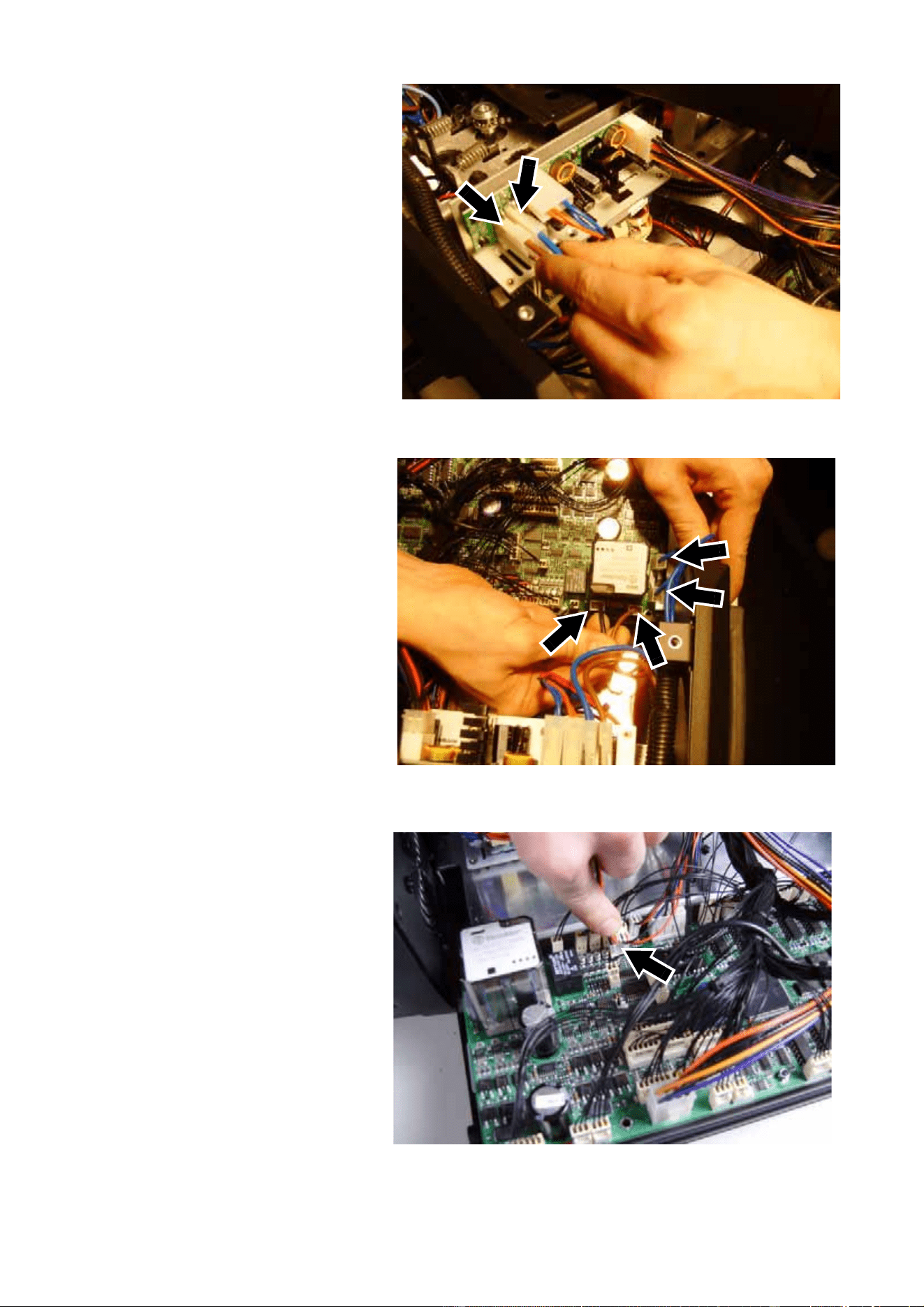
33. See Figure 31. Still working
with the ballast wiring
harness from the mains filter,
connect the double spade
connector with the blue leads
A to connector J8 beside the
lamp on/off relay, and
connect the double spade
connector with the brown
leads B to connector J5.
make sure that the double
spade connectors will not be
trapped or squeezed when
you close the PCB side
cover.
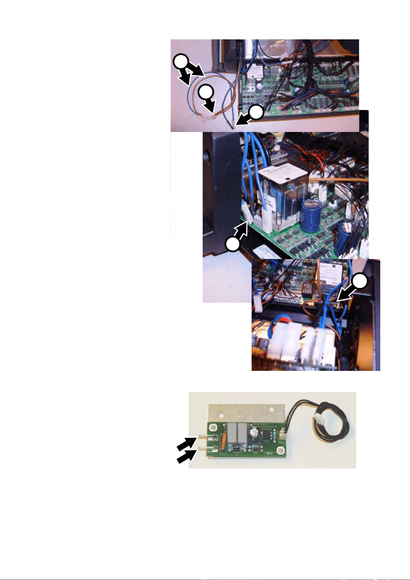
34. You are now left with one free
blue and one free brown lead
(C in Figure 31) connected to
the double spade connectors
you have just installed. See
Figure 32. Connect the free
blue lead and the free brown
lead to spade connectors
PL1 and PL2 (arrowed) on
the remote lamp on/off
opto-switch PCB you
installed in step 25. (photo
shows PCB before
installation). Polarity is not
important.
A
A
B
Figure 31
B
C
Figure 32
MAC 2000 Wash XB Upgrade Kit Installation Guide – Page 16 of 30
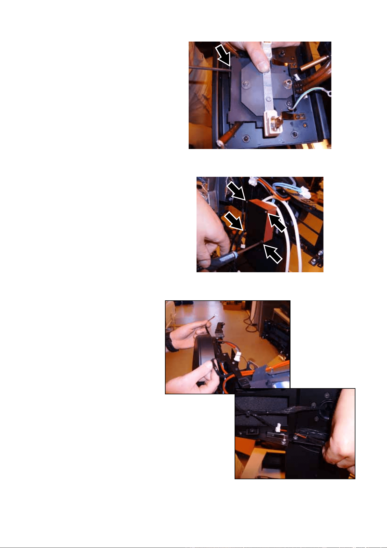
35. See Figure 33. Use a cable
tie to fasten the ballast wiring
harness in its sleeve along
the side panel and well away
from all moving parts.
36. See Figure 34. The
low-voltage leads from the
remote lamp on/off
opto-switch PCB to the
ballast and from the reduced
lamp power circuit on the
main PCB to the ballast must
also be secured. Use cable
ties to fasten them to the
main ballast output cable
sleeve as shown in the
photo.
Figure 33
Figure 34
MAC 2000 Wash XB Upgrade Kit Installation Guide – Page 17 of 30
37. See Figure 35. Connect the
brown Live power input lead
on the mains filter to the
spade connector A above the
existing brown lead on the
power on/off switch. Connect
the blue Neutral power input
lead on the mains filter to the
spade connector B above the
existing blue lead on the
power on/off switch.
38. Check that the new ballast is
correctly positioned in the
base. Lay the fixture on its
side and fasten the ballast
with the three Allen screws
(P/N 08111201, see “U” in
Table 1) supplied in the
Upgrade Kit, passing these
screws through the base in
the holes shown at A in
Figure 5 on page 6.
39. Reinstall the third screw from
the left in the bottom of the
base on the ballast side (see
Figure 4).
40. See Figure 36. Stand the
fixture upright again and
fasten the mains filter ground
lead to the base plate,
re-using the original screw in
the hole arrowed in Figure 36
and shown at D in Figure 18
on page 10.
41. Check that the wiring in the
base is correctly connected
with reference to “Schematic
wiring diagram” on page 4.
Check that all wiring is held
securely away from moving
parts. Attach wiring with extra
cable ties if necessary.
42. Reinstall the base side
covers shown in Figure 7 on
page 6. A new base cover A (P/N 55205504) for the main PCB side of the base and a new base
cover B (P/N 55205505) for the ballast side of the base are supplied in the Upgrade Kit. Fasten the
new covers’ ground leads to the base as shown in Figure 2 on page 5 and fasten the covers to the
base re-using the original eight PZ2 screws (P/N 08070502).
You will need to open the ballast side covers again for final safety testing after all work has been
completed. Closing the base covers at this point will ensure that no screws or other items fall into the
base while you work on the head.
Figure 35
A B
Figure 36
MAC 2000 Wash XB Upgrade Kit Installation Guide – Page 18 of 30
Replacement of components in the head
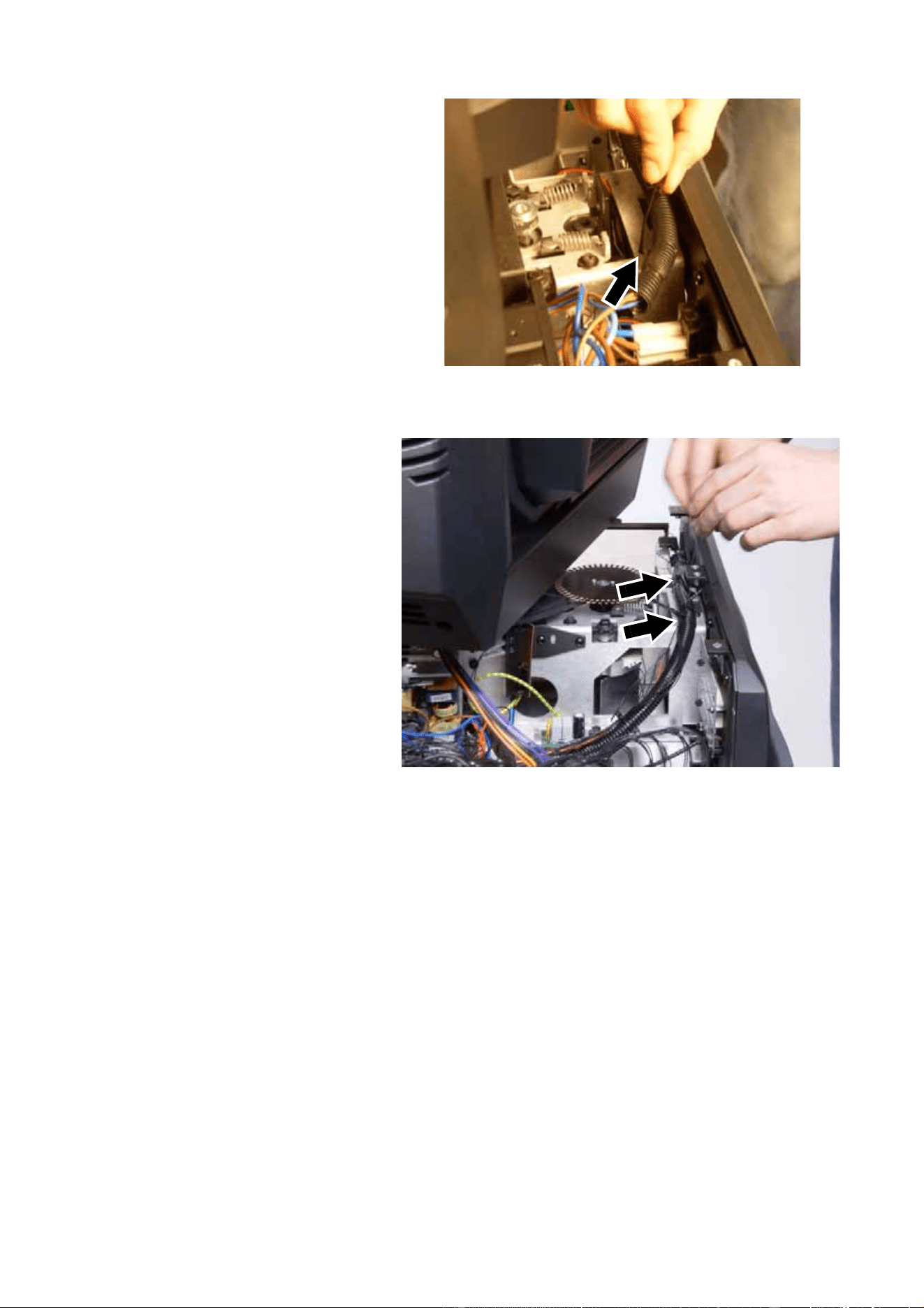
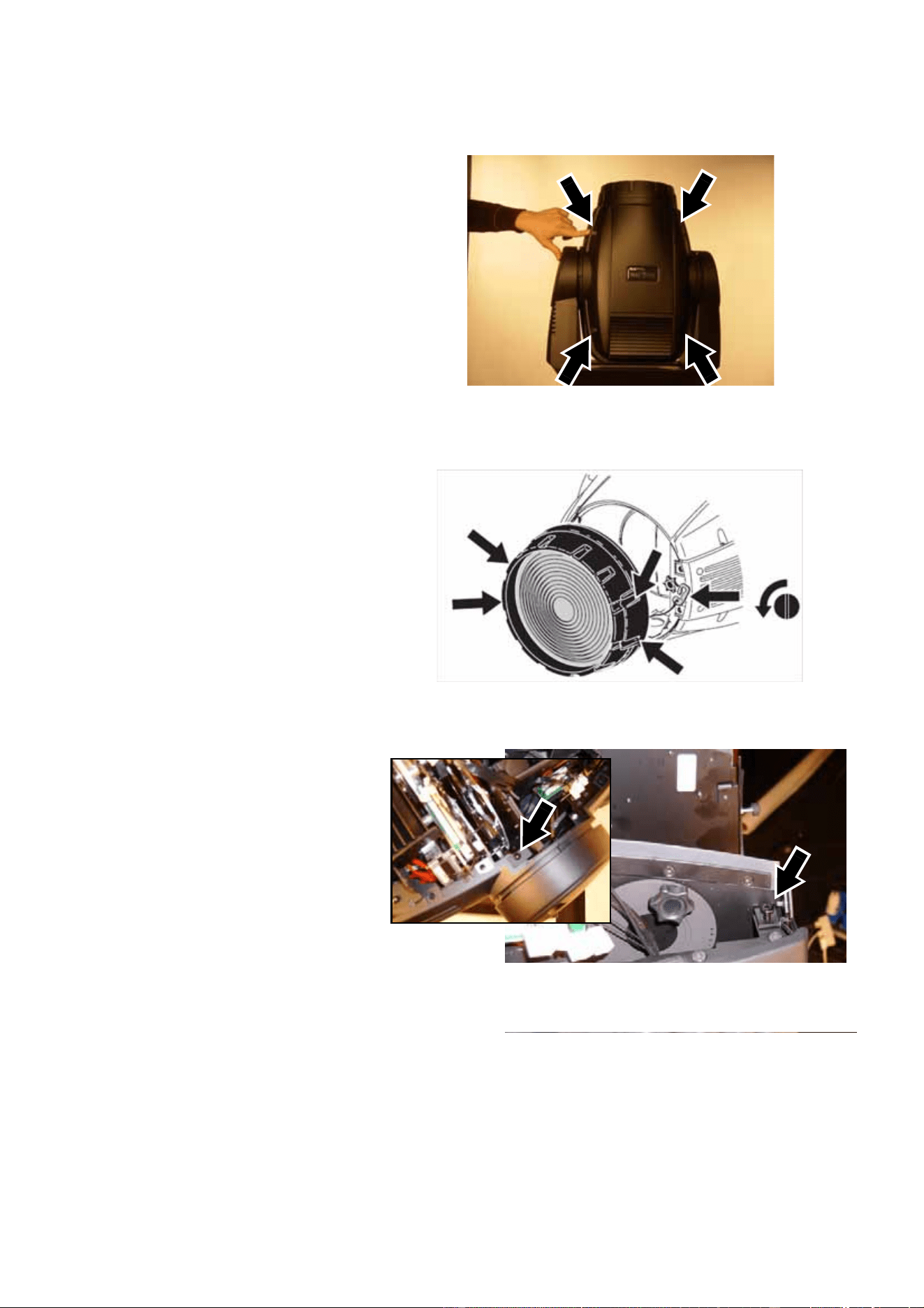
41. See Figure 37. Use a large
flathead screwdriver to
release the quarter-turn
retaining screws from both
head covers, unhook the
safety straps and remove the
covers. Keep the covers for
re-use.
42. See Figure 38. Use a large
flathead screwdriver to release
the four quarter-turn retaining
screws that hold the front lens,
loosen the safety strap
thumbscrew, unhook the
safety strap and remove the
front lens. Keep the lens for
re-use.
43. See Figure 39. Remove the
four zoom/focus module
retaining screws (PZ2, P/N
08070404), two on each side
of the head. Keep the screws
for re-use during
re-installation.
Figure 37
Figure 38
Figure 39
MAC 2000 Wash XB Upgrade Kit Installation Guide – Page 19 of 30
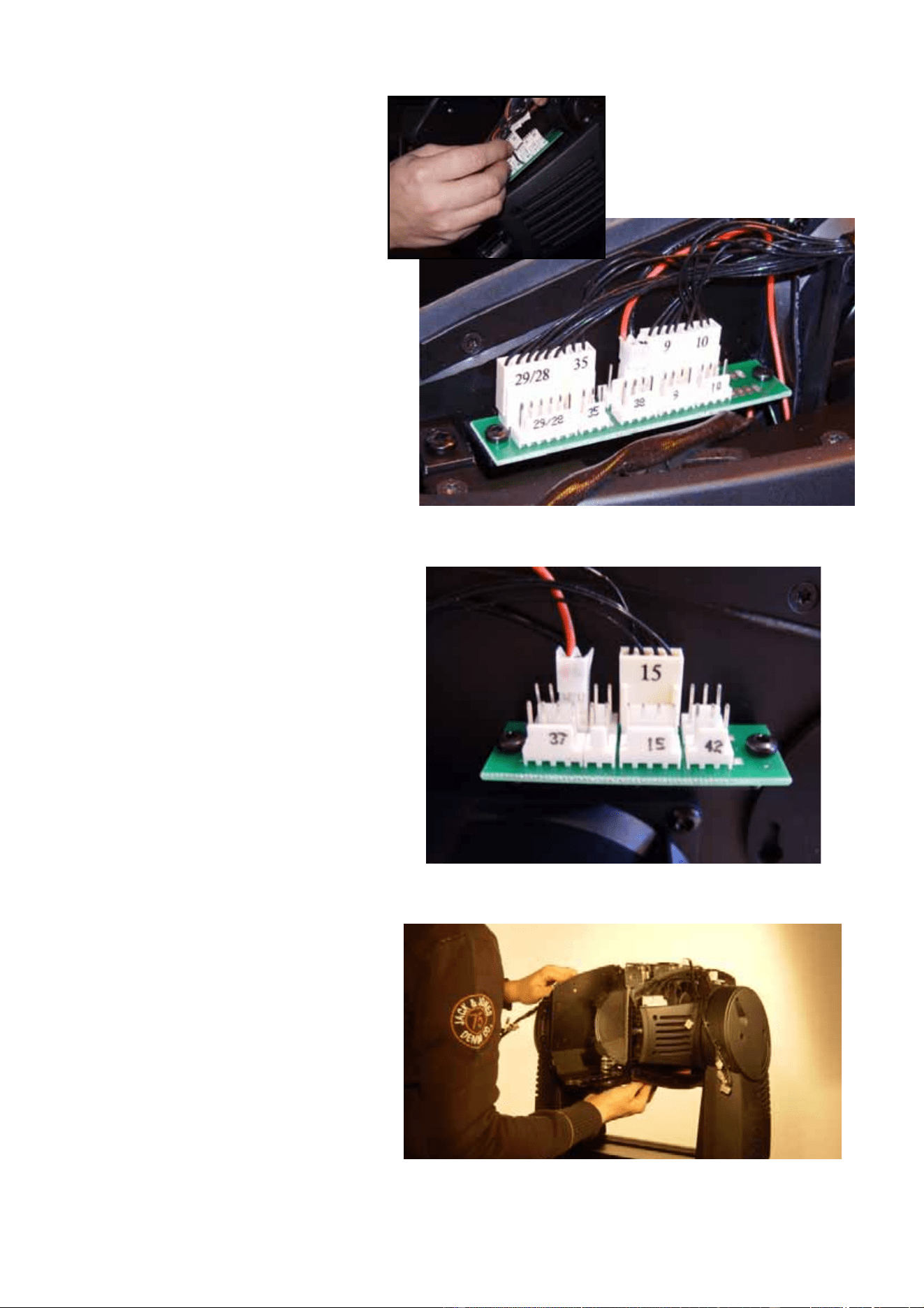
44. Disconnect all the outer row
of zoom/focus module
multi-connectors plus
number 38 connector on the
inner row on the left side of
the head, leaving the
connectors as shown in
Figure 40.
45. Disconnect all the
zoom/focus module
multi-connectors apart from
number 15 connector and a
connector at number 37 on
the inner row on the right side
of the head, leaving the
connectors as shown in
Figure 41.
46. See Figure 42. Lift the
zoom/focus module out of the
head and set it to one side.
Figure 40
Figure 41
Figure 42
MAC 2000 Wash XB Upgrade Kit Installation Guide – Page 20 of 30
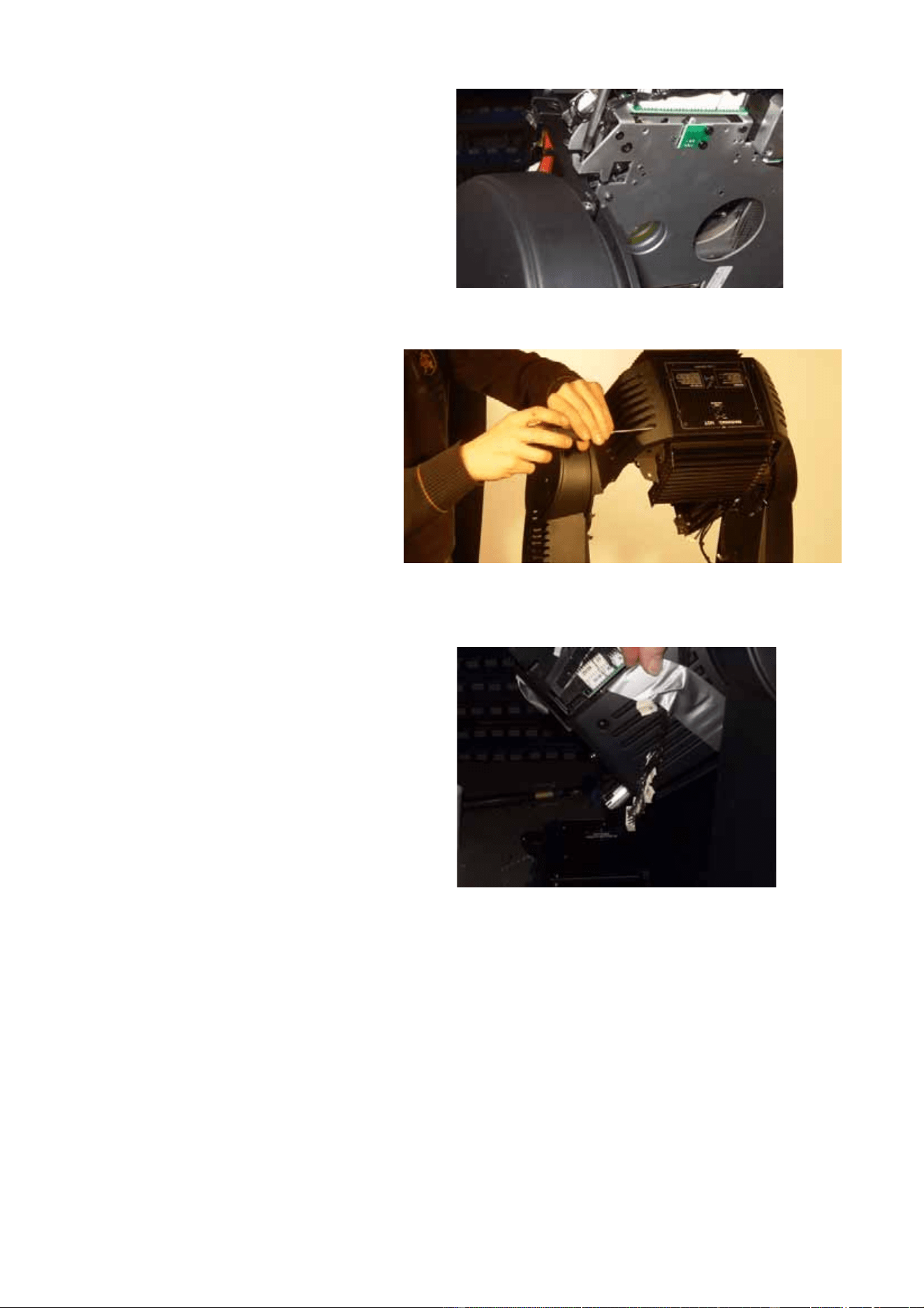
47. See Figure 43. Remove the
four screws (PZ2, P/N
08070404) that hold the CMY
module, disconnect the
module’s multi-connectors
marked 16, 17, 18, 19, 20,
34, 41 and T and lift the
module out of the head. Keep
the screws for re-use during
re-installation. This module is
no longer required, as a new
CMY module is supplied in
the Upgrade Kit.
48. See Figure 44. Remove the
two retaining screws (PZ2,
P/N 08070404) from each
rear head side cover and
remove both rear side
covers. Keep the screws and
covers for re-use during
re-installation.
49. Remove the two retaining
screws (PZ2, P/N 08070404)
from the left-hand front head
side cover and remove the
cover. Keep the screws and
cover for re-use during
re-installation.
50. See Figure 45. We
recommend that you tape
loose wiring to each side of
the head temporarily to keep
it out of the way and avoid
damage.
Figure 43
Figure 44
Figure 45
MAC 2000 Wash XB Upgrade Kit Installation Guide – Page 21 of 30
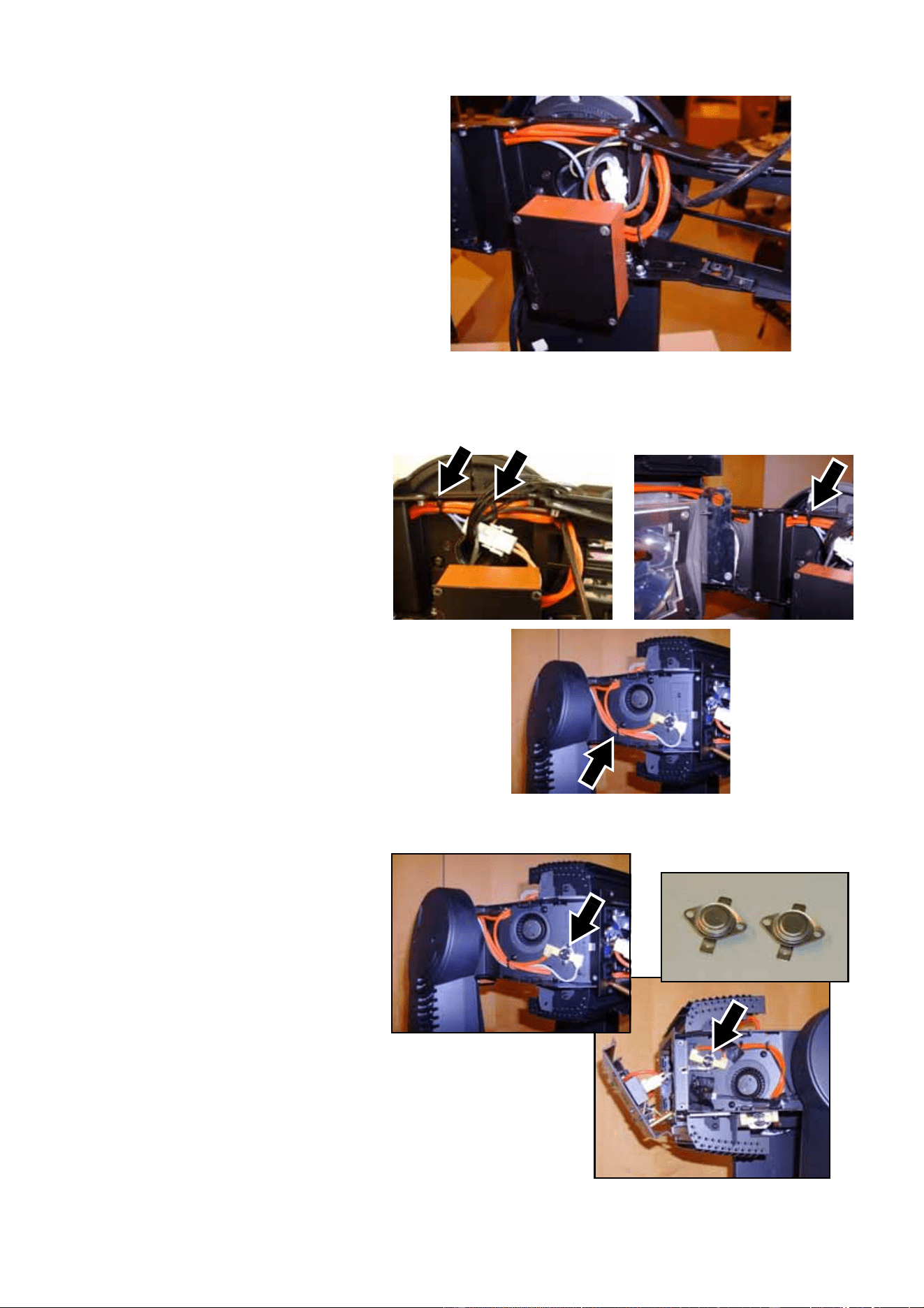
51. See Figure 46. Disconnect
the leads (arrowed) from the
thermoswitch on the
right-hand side lamp fan
assembly.
52. See Figure 47. Cut cable ties
as necessary and pull the
lamp fan power leads back
towards the fans on both
sides of the head until the
leads hang free. Remove the
fan mounting screws
(arrowed, PZ2, P/N
08200107) and remove both
the lamp cooling fans
complete with their metal
heat shields including the
thermoswitch mounted on
the right-hand heat shield.
Keep the screws for re-use
later. The fans with their heat
shields and thermoswitch are
no longer required, as new
items are supplied in the
Upgrade Kit.
53. See Figure 48. A total of four
new fans are supplied in the
upgrade kit. The two new
lamp cooling fans (right-hand
fan with thermoswitch =
P/N 62406058 and left-hand
fan = P/N 62406064) are
mounted on metal heat
shields. Install the new fans
with their heat shields,
re-using the existing
mounting screws. You are
screwing into the plastic fan
housings, so do not
overtighten screws. Install
the fan with the thermoswitch
on the right-hand side of the
fixture where the old
thermoswitch was, and
connect the spade
connectors from the old thermoswitch (see Figure 46) to the new one. Do not route fan power leads
to their connectors yet, as this is easier with the lamp leads from the ignitor to the lamp removed.
Figure 46
Figure 47
Figure 48
MAC 2000 Wash XB Upgrade Kit Installation Guide – Page 22 of 30
54. See Figure 49. Cut the cable
ties holding the ignitor wiring.
55. See Figure 50. Release the 4
quarter-turn screws (A) in the
rear lamp housing cover.
Open the cover and remove
the lamp. Remove the two
Torx 20 cover retaining
screws (B) to release the
lampholder/rear cover
assembly and let it hang from
the lamp leads and ground
lead (the photo shows the
lamp leads already released
from their terminals, but you
will release them in the next
step). Keep the rear cover
retaining screws for re-use.
56. See Figure 51. Unscrew the
lamp lead clamp screws A
and release the leads from
their terminals in the
lampholder. Unscrew and
release the lampholder
ground lead B. Release the
lamp lead clamp C.
Figure 49
Figure 50
B
A
A
A
A
Figure 51
A
A
B
C
MAC 2000 Wash XB Upgrade Kit Installation Guide – Page 23 of 30
57. See Figure 52. Release the
lamp rear plate by levering
with a flathead screwdriver
(arrowed), then pull the lamp
leads clear of the rear cover.
You can now remove the
lampholder /rear cover
assembly completely.
58. See Figure 53. Release the
lamp leads all the way
forward to the ignitor, noting
how the lamp leads are
routed. Disconnect the ignitor
input connector, remove the
four ignitor mounting screws
(arrowed) and remove the
ignitor. Keep the screws for
re-use. The ignitor is no
longer required, as a new
ignitor is supplied with the
Upgrade Kit.
59. See Figure 54. Route the
lamp fan leads from the fans
to the front of the head as the
original leads were routed.
Figure 52
Figure 53
Figure 54
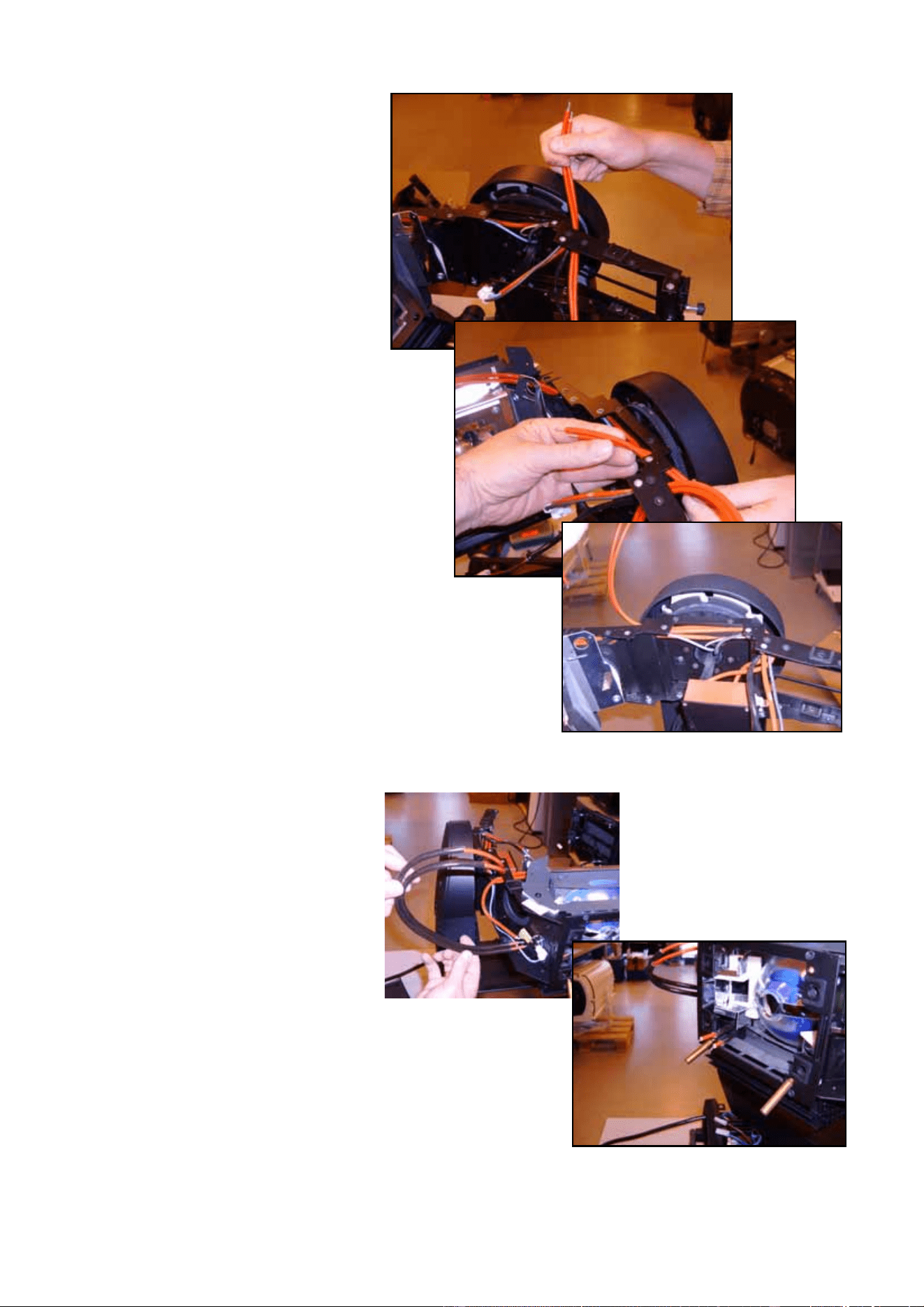
MAC 2000 Wash XB Upgrade Kit Installation Guide – Page 24 of 30
60. See Figure 55. Hold the
ignitor loosely in position and
route the lamp leads from the
ignitor back towards the lamp
compartment as the original
leads were routed.
61. See Figure 56. Install the
heat sleeve supplied in the
Upgrade Kit on the lamp
leads and thread the lamp
leads into the lamp
compartment.
Figure 55
Figure 56
MAC 2000 Wash XB Upgrade Kit Installation Guide – Page 25 of 30
62. See Figure 57. Hold the new
rear lampholder assembly
(P/N 55205111) supplied in
the Upgrade Kit up to the
back of the head and thread
the lamp leads behind the
rear lampholder plate
towards the lampholder
terminals. You may need to
release and remove the rear
lampholder plate temporarily
(as shown in the photo) to
make it easier to pass the
leads behind it.
63. See Figure 58. Clamp the
lamp leads into the
lampholder terminals A.
Fasten the lampholder
ground lead B to the head
re-using the original screw in
the same hole as the original
lead. Pull the lamp leads
towards the ignitor to
eliminate any slack in the
lampholder housing, but
make sure they are not
kinked or under tension.
Clamp the lamp leads in
place by applying the
push-on locking washer E
supplied with the Upgrade Kit
(P/N 08074402). Install the
lampholder/rear cover
assembly on its mounting pillars D in the back of the head, re-using the original screws. Apply
Loctite 243 on their threads before tightening.
64. See Figure 59. Pull the lamp
leads back through the fixture
towards the ignitor leaving
only enough slack as is
necessary to open the rear
lamp housing cover.
Important!Leave as little slack as possible
in the lamp leads in the lamp
housing.
Figure 57
Figure 58
A
A
B
C
D
D
E
Figure 59
MAC 2000 Wash XB Upgrade Kit Installation Guide – Page 26 of 30
65. See Figure 60. Fasten the
ignitor in its mounting bracket
re-using the original four
screws. Connect the ignitor
input connector. Secure
wiring with cable ties.
Important! Pull the lamp leads back
towards the ignitor so that the
only place where there is slack
in the leads is next to the
ignitor, as shown in Figure 60.
66. See Figure 61. Secure the
lamp leads with cable ties.
67. See Figure 62. Replace the
thermoswitches (arrowed) in
both sides of the head with
the two new thermoswitches
(P/N 05040023) supplied in
the Upgrade Kit, re-using the
existing screws.
Figure 60
Figure 61
Figure 62
MAC 2000 Wash XB Upgrade Kit Installation Guide – Page 27 of 30
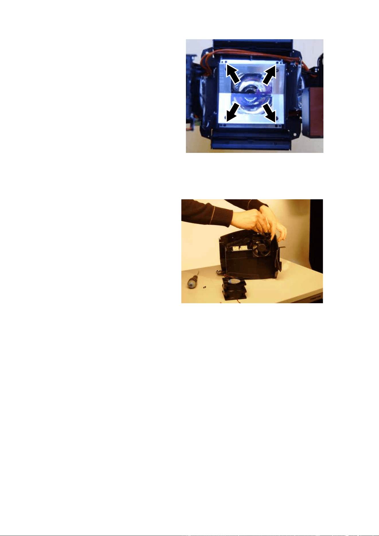
68. See Figure 63. Remove the 4
retaining screws (arrowed)
from the heat shield
assembly and remove the
assembly. You will need to
open the bend-over tabs and
move the thermoswitch
wiring out of the way for
access to two of the screws.
Keep the screws for re-use.
Now is a good time to clean
the reflector using 99.9%
isopropyl alcohol.
69. Install the new heat shield
assembly (P/N 62323015
supplied in the Upgrade Kit,
re-using the original screws,
with the bend-over tabs on
the same side as the
thermoswitch wiring. After tightening the screws, bend the tabs down to secure the thermoswitch
wiring around the upper side of the heat shield as it was previously.
70. See Figure 64. Place the
zoom/focus module on a
workbench. Cut the cable ties
holding the effect cooling fan
wiring. Disconnect the fans,
making a note of which
connectors they were
plugged into, then remove
the 4 mounting screws from
each fan and remove the
fans from the zoom/focus
module. The fans and
mounting screws are no
longer required, as new items
are supplied in the Upgrade
Kit.
Figure 63
Figure 64
MAC 2000 Wash XB Upgrade Kit Installation Guide – Page 28 of 30
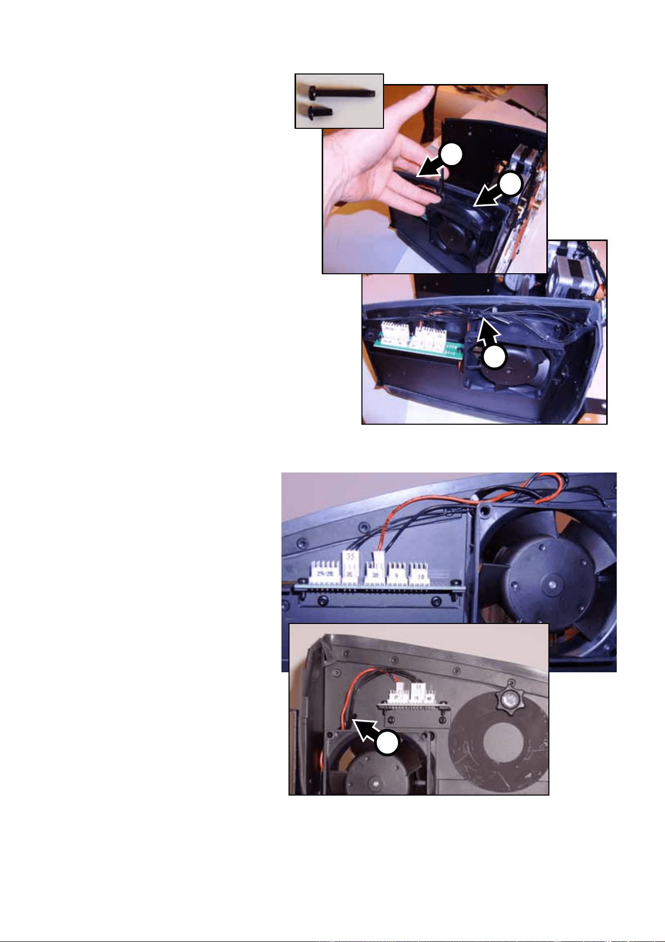
71. See Figure 65. Two new fans
(P/N 62222079) and eight
new mounting screws
(P/N 08070700) are supplied
in the Upgrade Kit. The new
screws are much shorter
than the fan mounting screws
you have just removed and
must be tightened on the
inner flanges (as shown at A)
of the fan housing, using a
screwdriver thin enough to
pass through the holes in the
outer flanges. Use the new
screws to install the 2 new
effect cooling fans in place of
the old ones. Install both fans
with their labels facing
inwards as shown in Figure
65 and install a wire retaining
clip (P/N 13101010) supplied
in the Upgrade Kit on the
front top mounting screw B of
the left-hand side fan and
rear top mounting screw of
the right-hand side fan.
72. Route all wiring out of the
way of the fans and plug the
fans into the connectors
where the old fans where
plugged in (see Figure 66).
Secure wiring with cable ties
and the wire retaining clips (C
in Figure 65 and Figure 66).
Make sure that leads cannot
hang in front of fans.
73. You have now installed all the
necessary components in the
head and zoom/focus
module.
74. Make a final check that all
wiring is routed away from
moving parts and
high-temperature
components and secured
with cable ties. Then install
the new CMY module
(P/N 55205110) supplied with
the Upgrade Kit and original
zoom/focus module,
replacing all connectors in
their original positions using
the numbering system to
guide you.
75. Clean or replace air filters, if necessary.
Figure 65
B
A
C
Figure 66
C
MAC 2000 Wash XB Upgrade Kit Installation Guide – Page 29 of 30
76. Replace all covers and replace the front lens, remembering to attach all safety straps.
Important!When installing the new lamp, take the precautions listed in the MAC 2000 Wash user manual to
avoid damage to the lamp.
77. Install the new 1500 watt lamp (P/N 97010322) supplied in the Upgrade Kit following the instructions
in the MAC 2000 Wash XB user manual (P/N 35000219) also supplied in the Upgrade Kit.
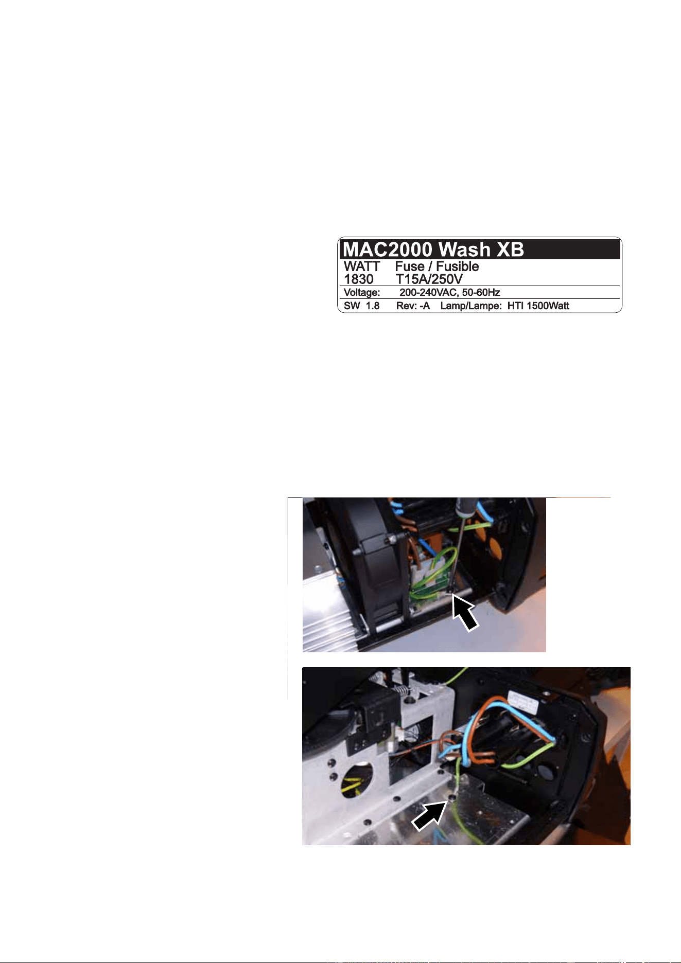
Product labelling
Warning! As soon as you have upgraded the
MAC 2000 Wash to the XB model, you
must apply the new product label (P/N
33140086) supplied in the Upgrade Kit
and illustrated in Figure 67 on top of
the serial number label, so that the
details of the XB model replace the
details of the existing model. Failure to
do so will create a significant safety
risk, void the product warranty and
make the product illegal.
Safety testing
Warning! The two tests described below must be carried out before the upgraded MAC 2000 Wash XB can
be considered safe. Do not operate the fixture until it has passed these tests.
Ground bond test (earth bond test)
68. Open the ballast side base
cover. Test the resistance
between the ground (earth)
conductor in the power cable
and each of the two ground
leads (see Figure 19) on the
chassis plate in turn. If
resistance exceeds 0.75 ohms,
clean and re-establish all
connections and repeat the test
until you measure less than
0.75 ohms between the ground
conductor in the power cable
and each of the two ground
leads. Do not proceed to the
next test until the fixture passes
this test.
69. Reinstall the ballast side cover.
Figure 67
Figure 68

MAC 2000 Wash XB Upgrade Kit Installation Guide – Page 30 of 30
High-potential dielectric withstand test
Warning! Dangerous voltage. Follow all safety instructions printed in your appliance tester’s user manual
and on your appliance tester.
70. Ensure that the fixture’s power cable is not connected to power. Temporarily link the live (brown) and
neutral (blue) conductors in the fixture’s power cable together so that there is electrical continuity
between them.
71. Connect one terminal of a PAT (portable appliance tester) device to the combined live and neutral
conductors in the fixture’s power cable. Connect the other terminal of the PAT device to the ground
conductor in the fixture’s power cable.
72. Make sure that the fixture’s main on/off power switch is set to ON.
73. You are about to apply a very dangerous and potentially lethal voltage. Ensure that it is impossible
for exposed conductive components in or on the fixture to come into contact with persons, or any
conductive surface or substance that persons may touch, during this test.
74. Set the maximum current on your PAT device to 20 mA, then use the PAT device to apply 1500 VAC
for a maximum of 1 second to the conductors you have connected it to.
75. If a flashover or arcing occurs, disconnect the PAT device, check all points of the installation, then
repeat the test.
76. Separate the live and neutral conductors again before connecting the fixture to normal AC power.
Lamp adjustment
Before operating an upgraded MAC 2000 Wash XB, carry out lamp adjustment as described in the MAC
2000 Wash XB user manual (P/N 35000219) supplied with the Upgrade Kit.
Product information
For specifications and other information about the product you have upgraded, please refer to the MAC
2000 Wash XB user manual supplied with the MAC 2000 Wash XB Upgrade Kit. This user manual is also
available for download from the Support area of the Martin website at http://www.martin.com.
Martin Professional A/S • Olof Palmes Allé 18 • 8200 Aarhus N • Denmark
Tel: +45 8740 0000 • Fax +45 8740 0010 • www.martin.com