MUCAR JS501/JS502
Quick Start Manual
Introduction to OBD Diagnostics
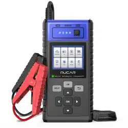
1. Product Descriptions
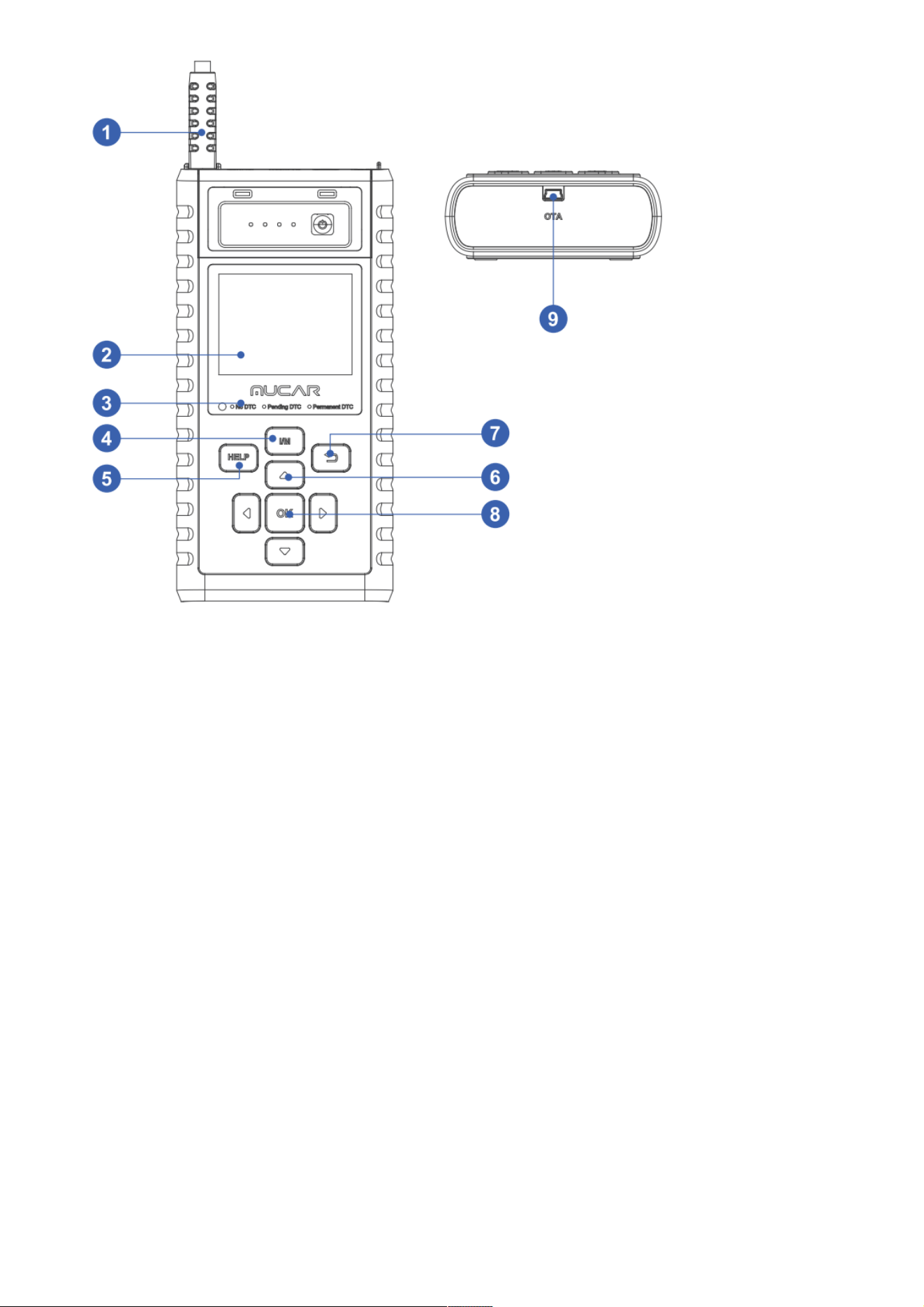
1.1 Diagnostic Cable: Standard OBDII diagnostic cable
1.2 LCD Display: 2.8 inch display (240*320)
1.3 Code severity alert: Three status indicators
1.4 I/M Button :Quickly enter "I/M READINESS" to view the data flow
1.5 Help: About OBD instructions, about data flow instructions, about printing instructions,
about exhaust ready instructions
1.6 Up, down, left and right keys: Used to select interactive functions
1.7 Return key: Return to upper function
1.8 OK Return: Confirm button
1.9 Mini usb:Used to upgrade software and print functions
Code Severity Alert
Code severity reminder: By reading the code, you can quickly determine whether your
vehicle needs to be repaired immediately, By reading the code, you can quickly determine
whether your vehicle needs to be repaired immediately or repaired until you get home.LED
indicator warning: There are three LED indicators on the barcode reader.NO DTC: Your
vehicle is in good condition. Pending DTC: You need to solve the problem and clear the
code. Permanent DTC: There is a serious problem with your vehicle. If these problems
cannot be resolved, you may fail the emission test.
EN
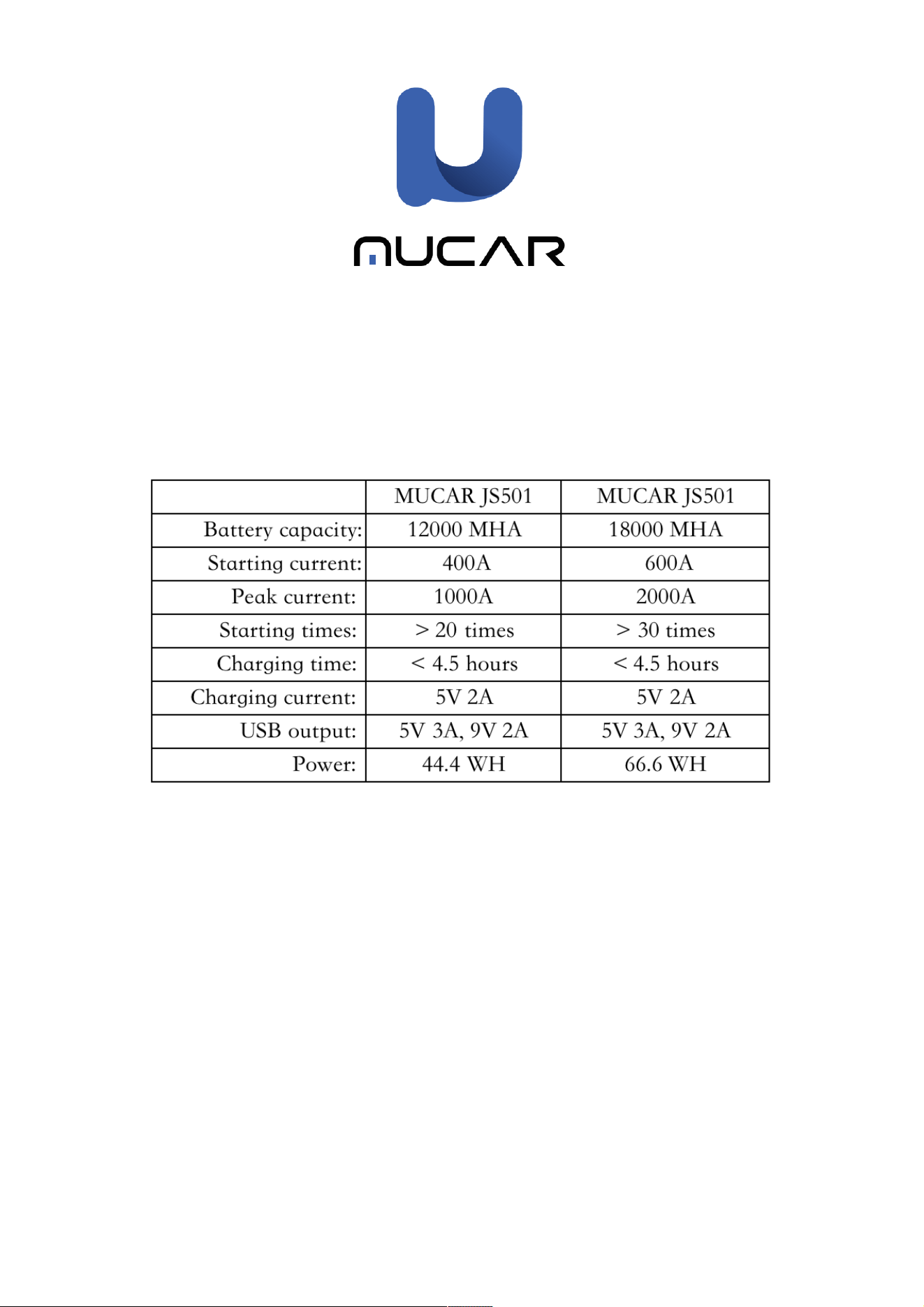
Technical Specifications
Display: 2.8 inch display
Working Environment: 0℃ ~ 50 ℃ (32 ~ 122 ℉ )
Storage Environment: -20℃ ~ 60℃ (-4 ~ 140 ℉ )
Power Supply: 9-18V vehicle power
Supported Protocols: ISO9141, KWP2000 (ISO 14230), J1850PWM,J1850VPM and CAN
OBDII protocol
Function Description
The most comprehensive personal OBD scanner
Compatible with vehicles after 1996 and vehicles with updated OBDII protocol
Read & clear DTCS, check and turn off engine light
Live data stream in graph for an effective troubleshooting
O2 sensor, on-board monitor & EVAP system for emission inspection
Built-in DTC lookup library, no need to search for DTC definitions
View VIN, CID and CVN, quickly read vehicle identification
Supports 8 Languages including English, French, Spanish, German, Russian, Polskie,
Italian and Portuguese
Prints diagnostic data report immediately for your inspection
2.How To Use
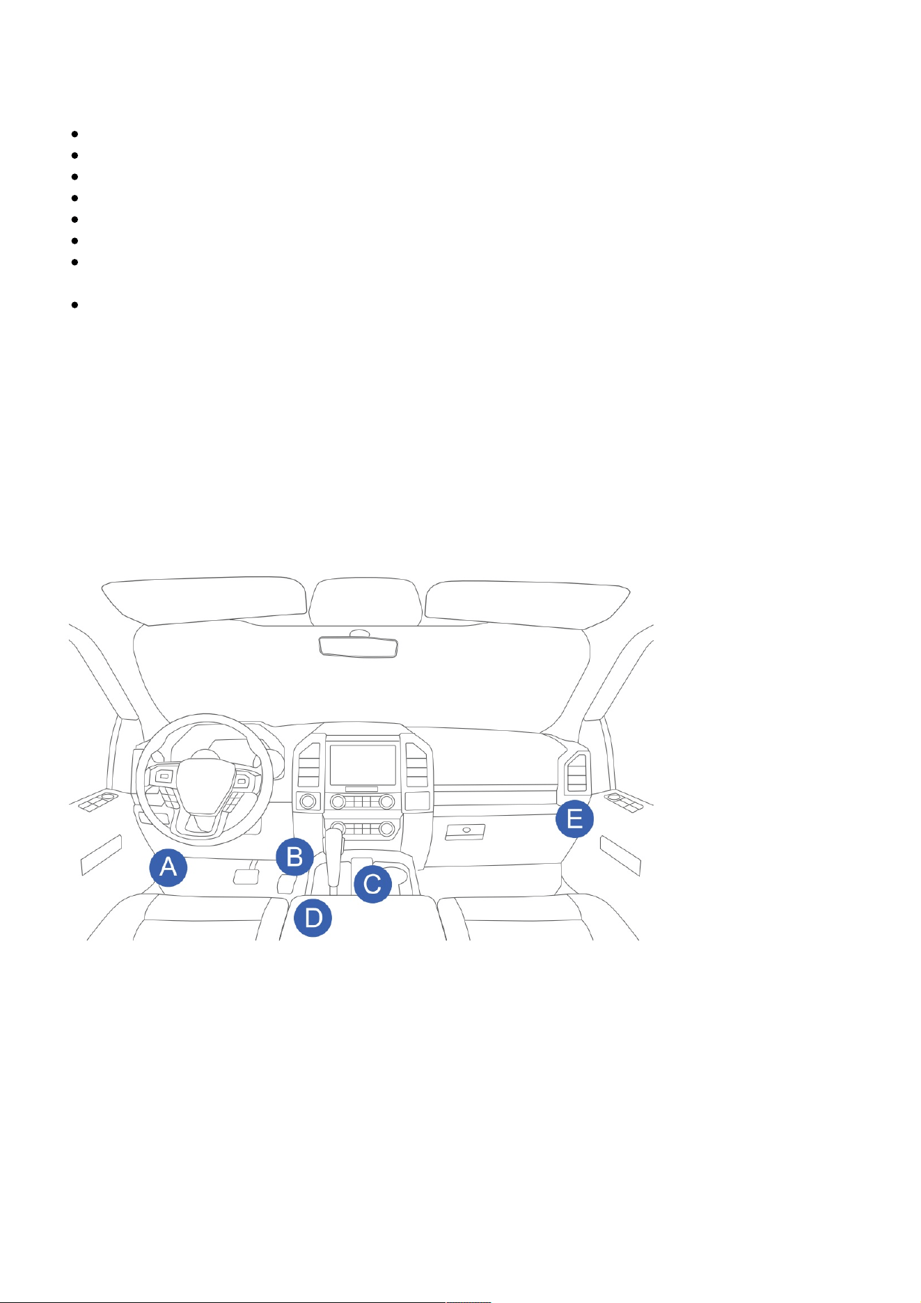
Data Link Connector (DLC) Location
The DLC (Data Link Connector or Diagnostic Link Connector) is typically a 16pin connector where
diagnostic code readers interface with the vehicle’s onboard computer. The DLC is usually
located 12 inches from the center of the instrument panel (dash), under or around the driver’s
side for most vehicles. If Data Link Connector is not located under dashboard, a label should be
there telling location. For some Asian and European vehicles, the DLC is located behind the
ashtray and the ashtray must be removed to access the connector. If the DLC cannot be found,
refer to the vehicle’s service manual for the location.
Note: Turn on the ignition of the vehicle, the voltage range of the device should be 9-18V,
and the throttle should be in the closed position.
Application Overview
When the code reader boots up, the Home screen opens. This screen shows all applications
loaded on the unit. Following applications are preloaded into the code reader:
● Diagnostics : leads to OBDII screens for all 9 generic OBD system tests.
● IM Readiness:option allows to view a snapshot of the operations for the emission system
on OBDII/EOBD vehicles.
● Lookup : leads to screens for diagnostic trouble code lookup.
● Review Data : leads to screens for access to tested data files.
● Print : leads to screens for access to printing function

● Help : You will find the device OBD function and system instructions
● Setup :leads to screens for adjusting default settings to meet your own preference when
using the code reader.
● Info : leads to screen that shows information about the code reader.
2.1 Select "Diagnosis", click "OK" to enter the system diagnosis, select the vehicle type,
and enter the diagnosis function list.Select "READ CODE" and click "OK" to select vehicle
type to view DTC diagnostic data,Select "ERASE CODES" to clear the fault code,Select”
I/M READINESS” and click "OK" to view the I/M data flow,Select "DATA STREAM" View all
data streams,Next click "OK", and finally you can view the graphics data flow,Select
"FREEZE FRAME" and click "OK" to view the freeze frame data stream,Select "O2 SENSOR
TEST" and click "OK" to view O2 Sensor data Stream,Select "ON-BOARD MONITORING"
and click "OK" to view On-Board Monitor data streams,Select "EVAP SYSTEM” and click
"OK" to view EVAP data streams.
2.2 Select” I/M READINESS” and click "OK" to view the I/M data flow.
2.3 Select "REVIEW" and click "OK" to enter the REVIEW DATA list. Select "Review DTC" and
Next "OK" to View diagnostic records and delete records.
2.4 Select "DTC LOOKUP" and click "OK" to query fault code analysis
2.5 Select "Print" and click "OK" to enter th e "UPLOAD RECORD" interface to view the
prompts, click "Help and I/M" to view the prompts and operate whether to delete the
information.
2.6 Select "Help" and click "OK". You will find the device OBD function and system
instructions.
2.7 Select "Settings" and click "OK" to set the native language, unit of measure, record
mode and sound .
2.8 Select "info" and click "OK" to view local information .
EN
3. Update
The tool can be updated via a USB cable.
Note: Make sure that your computer has Internet connection.
3.1 Please log in to http://www.mythinkcar.com official website and find the "THINKOBD
Updata TOOL", download tool "Product Updata Tool Setup.exe" on your computer. Unzip
and install it on your computer (compatible with Windows XP, 7, 8, and 10).
3.2 When the installation is complete, connect one end of the USB data cable to the USB
port of the computer, Type-c port on the other end of the tool.
3.3 . First insert the device into the computer identification port, then open the JS501/502
upgrade tool. Find the "COMFLG.INI" file and open, and change the "Serial Name" in the file
as same as the computer and device port "USB-COM name"
3.4 Finally, open the "CReaderV Plus Upgrade Tool.exe" of the JS501/502 installation
package file, and click "Start Upgrade" to complete the upgrade.
4. Vehicle Connection
4.1 Locate vehicle’s DLC socket: The DLC (Diagnostic Link Connector) is usually located 12
inches form the center of the steering wheel under or around the driver’s side for most
vehicles, if the DLC cannot be found refer to the vehicle’s service manual for the location
4.2 Connect the diagnostic cable to the vehicle’s DLC ,the tool will be automatically powered
up.
4.3 The tool is now ready to work.
Caution:
Don’t forget to remove the MUCAR emergency starter powerFrom the OBD port after use.
Keep the MUCAR emergency starter poweraway from water,gasoline or any other liquids.
Introduction to Emergency Activation
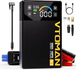
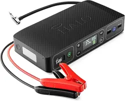
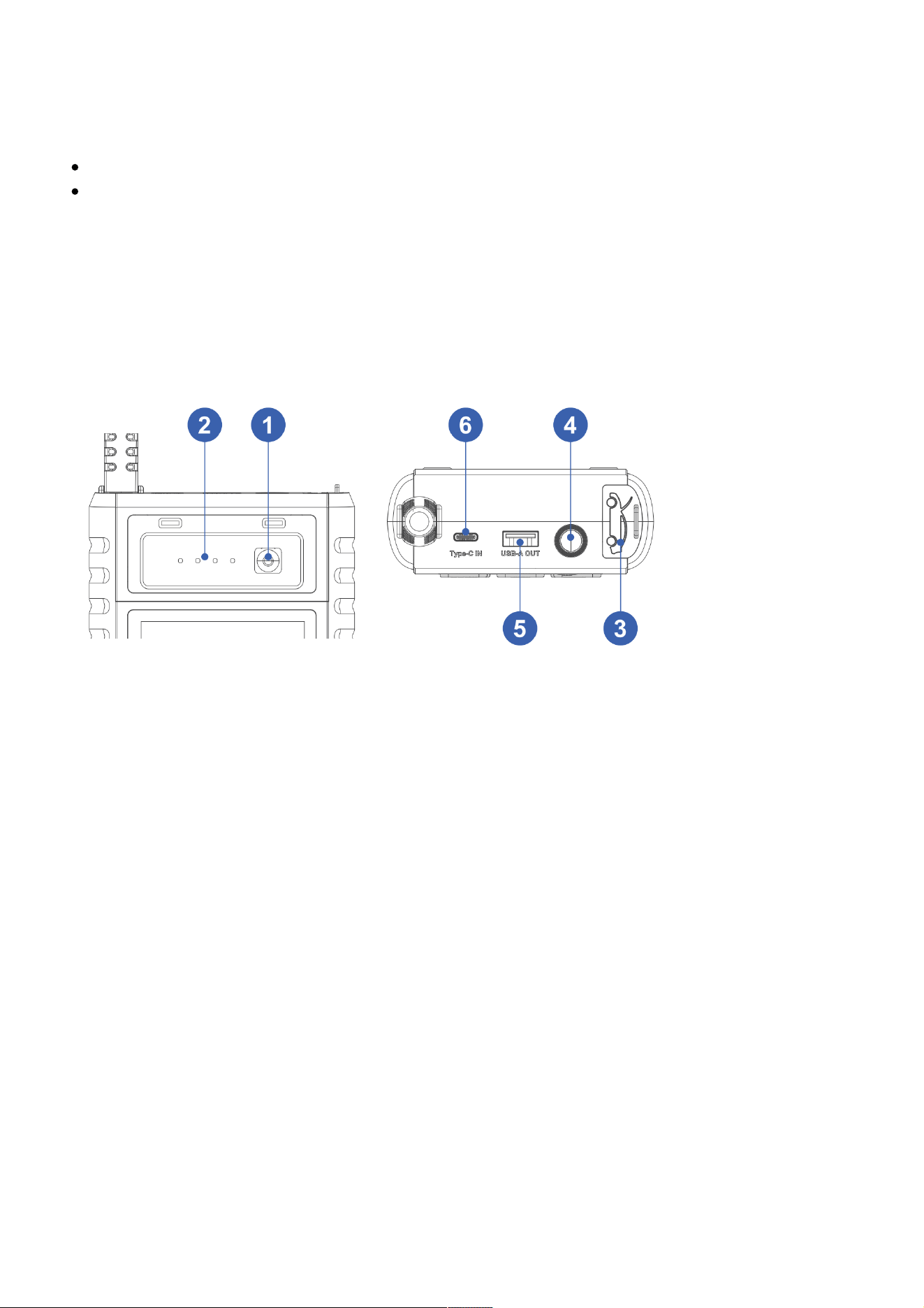
5. Product Introduction
5.1 ON/OFF : Long press 5 seconds to switch on/off
5.2 Power display light : Display the remaining power
5.3 Battery clip insertion port : Correctly inserted into the emergency start interface ,red and
black battery clip corresponds to the positive and negative battery poles.
5.4 LED work light : Diapay the working status
5.5 USB-A out : Cell phone and other electronic devices charging port
5.6 TYPE-C in :Emergency power charging port . Important reminder, Please do not short-circuit
the emergency start interface measurement!
6. How To Use.
6.1 Will be equipped with a power adapter into the charging socket
6.2 The power adapter plug into the host 5V3A input TYPE-C port
To 12V car start
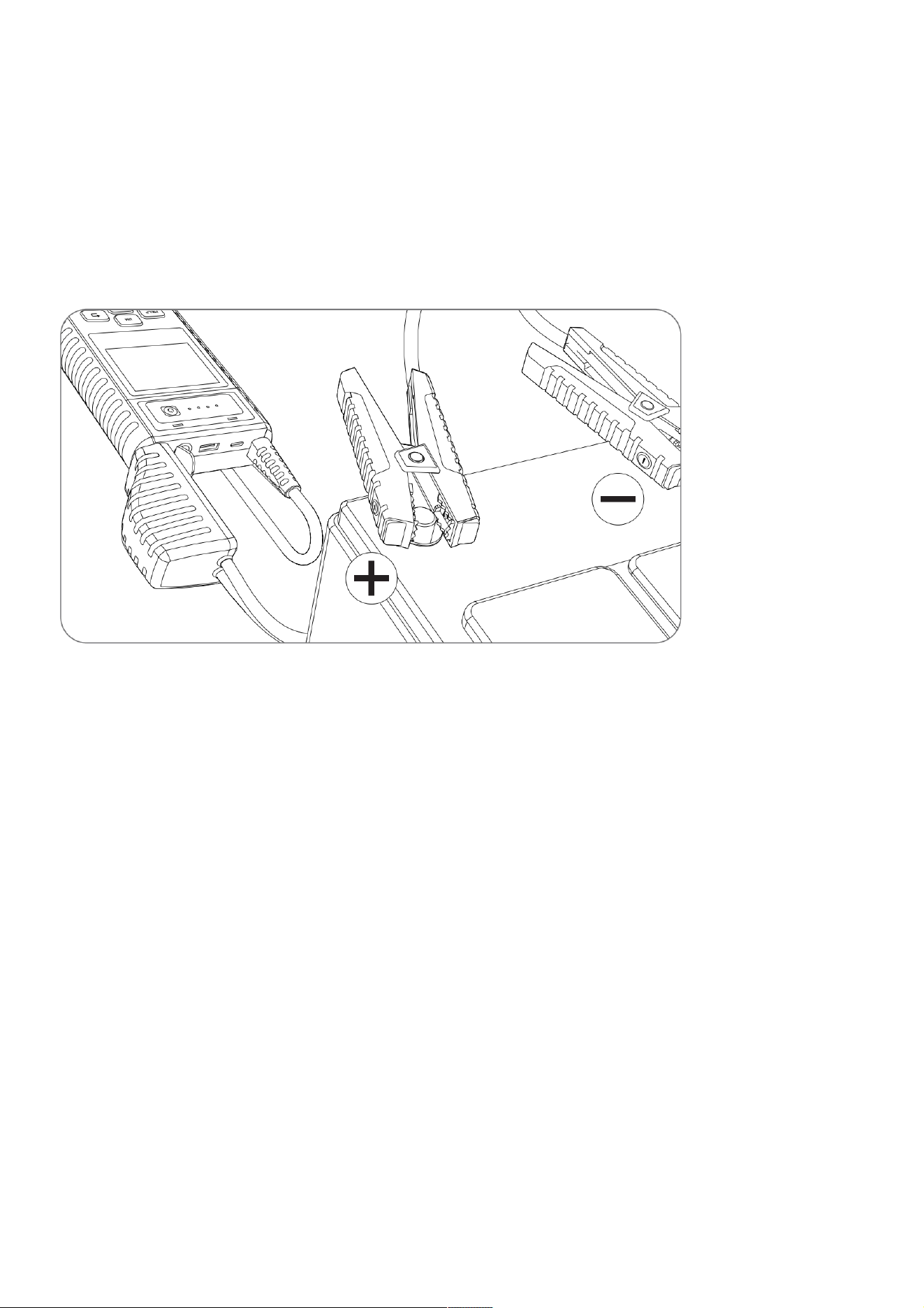
6.3 To confirm that the host power indicator in more than 60% (more than 3 grid power).
6.4 The red clip clamps the positive (+) pole of the battery, the black clip clamps the negative (-)
pole of the battery
6.5 The battery cable connector into the car interface of the starter power
6.6 Turn the car ignition switch to the start (START) position
6.7 After the car starts, unplug it immediately
6.8 Remove the battery clip clamp
Charging mobile phones/tablets and other electronic products
6.9 Select the appropriate charging connector and adapter cable
6.10 Connect the USB-A OUT output port of the adapter cable to the charging connector to the
phone/tablet and other electronic products. (Support Output:5V-3A, 9V-2A, 12V-1.5A)
6.11 Touch the switch button to start charging mobile phones/tablets and other electronic
products
LED light different modes switch
Press the display switch button for a second to start the light lighting function. Then short press
the switch button, in order to: strong light, flashing, SOS mode.
Tip: The product does not contain the following toxic and harmful elements

7. Frequently Asked Questions:
7.1 Q: How to turn off the mobile power?
A: The product has an intelligent detection function, once there is no load, or the end of
charging electronic products, the mobile power will automatically hibernate to save power so as
not to lose.
7.2 Q: How long does it take to charge the device to the host?
A: Home or car charger through the TYPE-C input takes about 4.5 hours to be completely full.
7.3 Q: How many times can the device charge the phone?
A: Depends on the capacity of your phone battery size, Iphone13 for example, can be filled 4
times.
7.4 Q: How many times can the device start a 3.0L gasoline car?
A: It can start the car about 25 times continuously.
7.5 Q: How long is the life of the device?
A: Under normal use, it can be used for 3-5 years.
7.6 Q: The device is fully charged and not used, how long can be stored to start the car?
A: The circuit design of the device is very scientific, do not use the storage 6-12 months are no
problem, but in order to extend the service life, it is recommended that every three months
charging.
7.7 Q: Touch the switch button, the product does not have any response
A: Because the product voltage is too low, low-voltage protection function to start, cut off the
circuit, please insert the charging plug into the 15V1A input port to activate
8. Warranty Terms
This warranty applies only to users and distributors who purchase MUCAR INC
www.mythinkcar.com MUCAR JS501/502 products through normal procedures. Provide free

warranty within one year. MUCAR warranty including electronic products for damages
caused by defects in materials or workmanship. Damages to the equipment or components
caused by abusing, unauthorized modification, using for non-designed purposes, operation
in a manner not specified in the instructions, etc.are not covered by this warranty. The
compensation for dashboard damage caused by the defect of this equipment is limited to
repair or replacement. MUCAR does not bear any indirect and incidental losses. MUCAR will
judge the nature of the equipment damage according to its prescribed inspection methods.
No agents, employees or business representatives of MUCAR are authorized to make any
confirmation, notice or promise related to MUCAR products.
Please contact Online Customers Service via the order interface.
Customer Service Email: support@mythinkcar.com
Official Website: www.mythinkcar.com
Products tutorial, videos, FAQ and coverage list are available on MUCAR official website.