

M1 MkII Owner’s
Manual

Table of contents
▪ 1: Product Safety and Conformity . . . . . . . . . . . . . . . . . . . . . . . . . . . . . . . . . . . . . . . . . . . . . . . . . . . . 3
▪ 2: Introduction . . . . . . . . . . . . . . . . . . . . . . . . . . . . . . . . . . . . . . . . . . . . . . . . . . . . . . . . . . . . . . . . . . 5
▪ 3: Installation . . . . . . . . . . . . . . . . . . . . . . . . . . . . . . . . . . . . . . . . . . . . . . . . . . . . . . . . . . . . . . . . . . . 6
▪ 3.1: Electrical Installation . . . . . . . . . . . . . . . . . . . . . . . . . . . . . . . . . . . . . . . . . . . . . . . . . . . . . . . 7
▪ Speaker Cables . . . . . . . . . . . . . . . . . . . . . . . . . . . . . . . . . . . . . . . . . . . . . . . . . . . . . . . . . . 7
▪ Signal Wiring . . . . . . . . . . . . . . . . . . . . . . . . . . . . . . . . . . . . . . . . . . . . . . . . . . . . . . . . . . . . 7
▪ 3.2: Positioning . . . . . . . . . . . . . . . . . . . . . . . . . . . . . . . . . . . . . . . . . . . . . . . . . . . . . . . . . . . . . . 9
▪ Orientation . . . . . . . . . . . . . . . . . . . . . . . . . . . . . . . . . . . . . . . . . . . . . . . . . . . . . . . . . . . . . . 9
▪ 4: Setting up and adjusting. . . . . . . . . . . . . . . . . . . . . . . . . . . . . . . . . . . . . . . . . . . . . . . . . . . . . . . . 11
▪ 4.1: First time power up with DA2 or DCA800/1400 . . . . . . . . . . . . . . . . . . . . . . . . . . . . . . . . . . 12
▪ 4.2: Running in . . . . . . . . . . . . . . . . . . . . . . . . . . . . . . . . . . . . . . . . . . . . . . . . . . . . . . . . . . . . . 13
▪ 4.3: Testing and alignment. . . . . . . . . . . . . . . . . . . . . . . . . . . . . . . . . . . . . . . . . . . . . . . . . . . . . 14
▪ System Gain/Level Calibration . . . . . . . . . . . . . . . . . . . . . . . . . . . . . . . . . . . . . . . . . . . . . . . 14
▪ 5: Protection . . . . . . . . . . . . . . . . . . . . . . . . . . . . . . . . . . . . . . . . . . . . . . . . . . . . . . . . . . . . . . . . . . 15
▪ 6: Care and Maintenance . . . . . . . . . . . . . . . . . . . . . . . . . . . . . . . . . . . . . . . . . . . . . . . . . . . . . . . . . 16
▪ 7: Servicing & Spare parts . . . . . . . . . . . . . . . . . . . . . . . . . . . . . . . . . . . . . . . . . . . . . . . . . . . . . . . . 17
▪ 8: Technical Specifications . . . . . . . . . . . . . . . . . . . . . . . . . . . . . . . . . . . . . . . . . . . . . . . . . . . . . . . . 18
2 M1 MkII Owner’s Manual
1: Product Safety and
Conformity
The M1 MkII is a professional loudspeaker intended for professional users working in a professional environment;
therefore, a certain level of knowledge of audio equipment operation is assumed.
About this guide
Used expressions and symbols
In this guide, the following signs and symbols are used:
The exclamation point within an equilateral triangle is intended to alert the user to the presence of important
operating and maintenance (servicing) instructions in the literature accompanying the product.
WARNING
Indicates, in combination with a safety sign, a potentially hazardous situation which, if not avoided, could result in
death or serious injury.
Important safety instructions
1. Read these instructions.
2. Keep these instructions.
3. Heed all warnings.
4. Follow all instructions.
5. Do not use this apparatus near water.
6. Clean only with a dry cloth.
7. Do not install near any heat sources such as radiators, heat registers, stoves, or other apparatus (including
amplifiers) that produce heat.
8. Only use attachments/accessories specified by the manufacturer.
9. Use only with the cart, stand, tripod, bracket, or table specified by the manufacturer, or sold with the
apparatus. When a cart is used, use caution when moving the cart/apparatus combination to avoid injury
from tip-over.
10. No naked flame sources, such as lighted candles, should be placed on the apparatus.
WARNING
To reduce the risk of fire or electric shock, this apparatus should not be exposed to rain or moisture and objects
filled with liquids, such as vases, should not be placed on this apparatus.
WARNING
1: Product Safety and Conformity 3

Our speakers are very heavy. Ensure appropriate lifting methods are employed when moving them.
WARNING
Never place a loudspeaker in an unstable location. A loudspeaker may fall, causing serious personal injury or
death. Use only appropriate stands or brackets to mount the loudspeaker.
High sound pressure levels
To prevent possible hearing damage, avoid listening at high volume levels for extended periods of time.
Unpacking
After unpacking, ensure the system is complete and inspect the device and all accessories for any transport
damage. Transport damage may be expected if the packaging is already severely damaged. Do not attempt to
start up a damaged device.
If the contents are incomplete or damaged, please contact your Dynaudio distributor.
Distributor addresses can be found on the Internet at dynaudio.com.
Removing the protection cap
The tweeter is protected by a cap to prevent damage during transport and unpacking. After you have unpacked
the speaker, remove the cap by just pulling it straight out.
Packaging material
The packaging has been designed to be reusable, provided it has not been damaged during transport. Keep the
original packaging and use it for all further transport.
CE declaration of conformity
The CE declaration of conformity can be found online:
https://dynaudio.com/support/ce-conformity-declarations
Correct disposal of this product
This marking on the product, accessories, packaging or literature indicates that the product and its electronic
accessories should not be disposed of with other household waste as stated in the European Directive 2012/19/
EU on Waste Electrical and Electronic Equipment (WEEE). The crossed-out bin symbol is printed on all products
as a reminder.
By ensuring this product is disposed of correctly, you will help prevent potential negative consequences for the
environment and human health. Recycling of materials helps to conserve natural resources.
Household users should contact either the retailer where they purchased this product or their local government
oce for details on where and how to recycle these items in an environmentally safe manner.
Business users should contact their supplier and check the terms and conditions of the purchase contract. This
product and its electronic accessories should not be mixed with other commercial wastes for disposal.
Waste may be taken to a special collection site or can be delivered free of charge to the dealer when purchasing
a new equivalent or without obligation to make a new purchase for equipment smaller than 25 cm.
4 M1 MkII Owner’s Manual

2: Introduction
The M1 MkII is a 2-way passive monitor system designed as a high-quality nearfield monitor. It is typically used
with a stereo power amplifier, such as the Dynaudio Acoustics DA2 or DCA800.
For surround monitoring applications, the M1 MkII is typically complemented by a sub-bass loudspeaker system,
along with surround speakers as needed.
2: Introduction 5

3: Installation
6 M1 MkII Owner’s Manual
3.1: Electrical Installation
In view of the “custom” nature of every installation for a monitor of this type, no cabling is supplied. The following
are required for the electrical installation of the M1 MkII system.
Speaker Cables
The connections between the speaker and amplifier should be kept as short as possible. The cable itself should
be high-quality speaker cable, eg 2.5 mm², 4 mm² or 6 mm² oxygen-free multi-strand copper. The speaker
terminations are on Gold screw down terminals.
The outputs of the amplifiers are on speakON connectors.
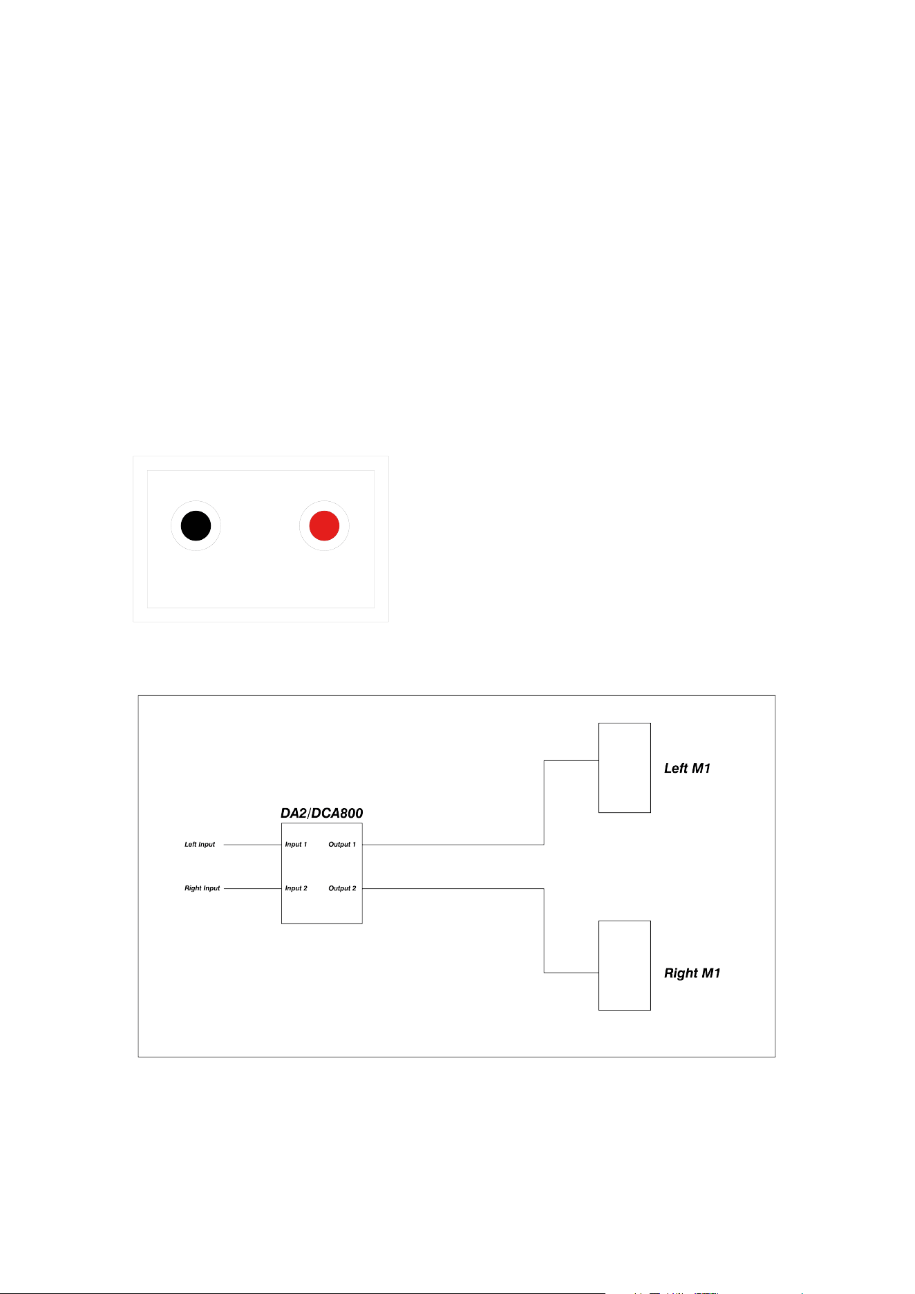
Signal Wiring
The inputs are balanced XLR connections. Always ensure that only high-quality XLR cables are used for
connection to the amplifiers. Typical system wiring configurations are shown in Figures 2 and 3.
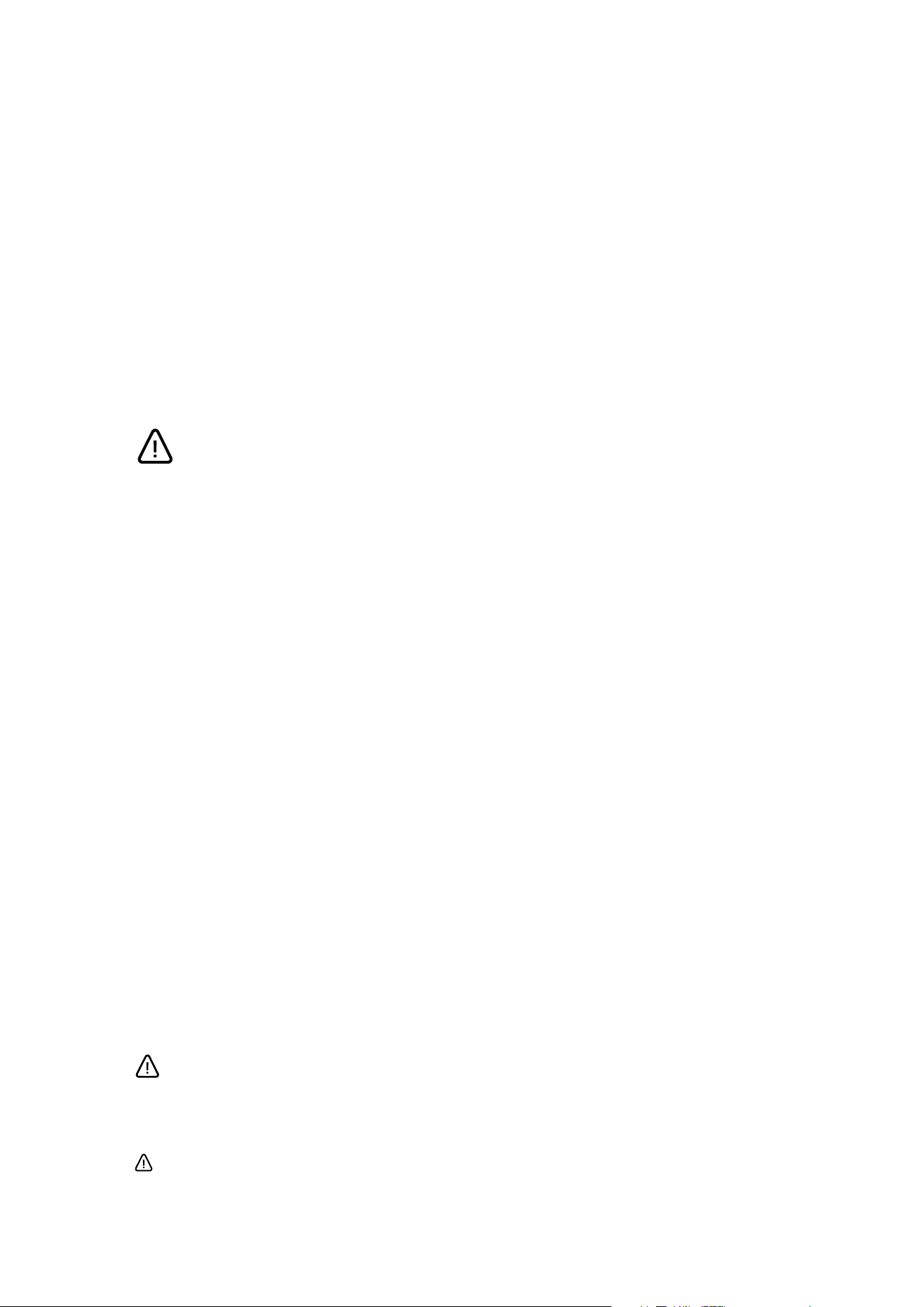
Figure 1: M1 MkII Connector panel. Red indicates +ve.
Figure 2a: Typical Stereo M1 MkII system with DA2/DCA800 amplifier
3: Installation 7
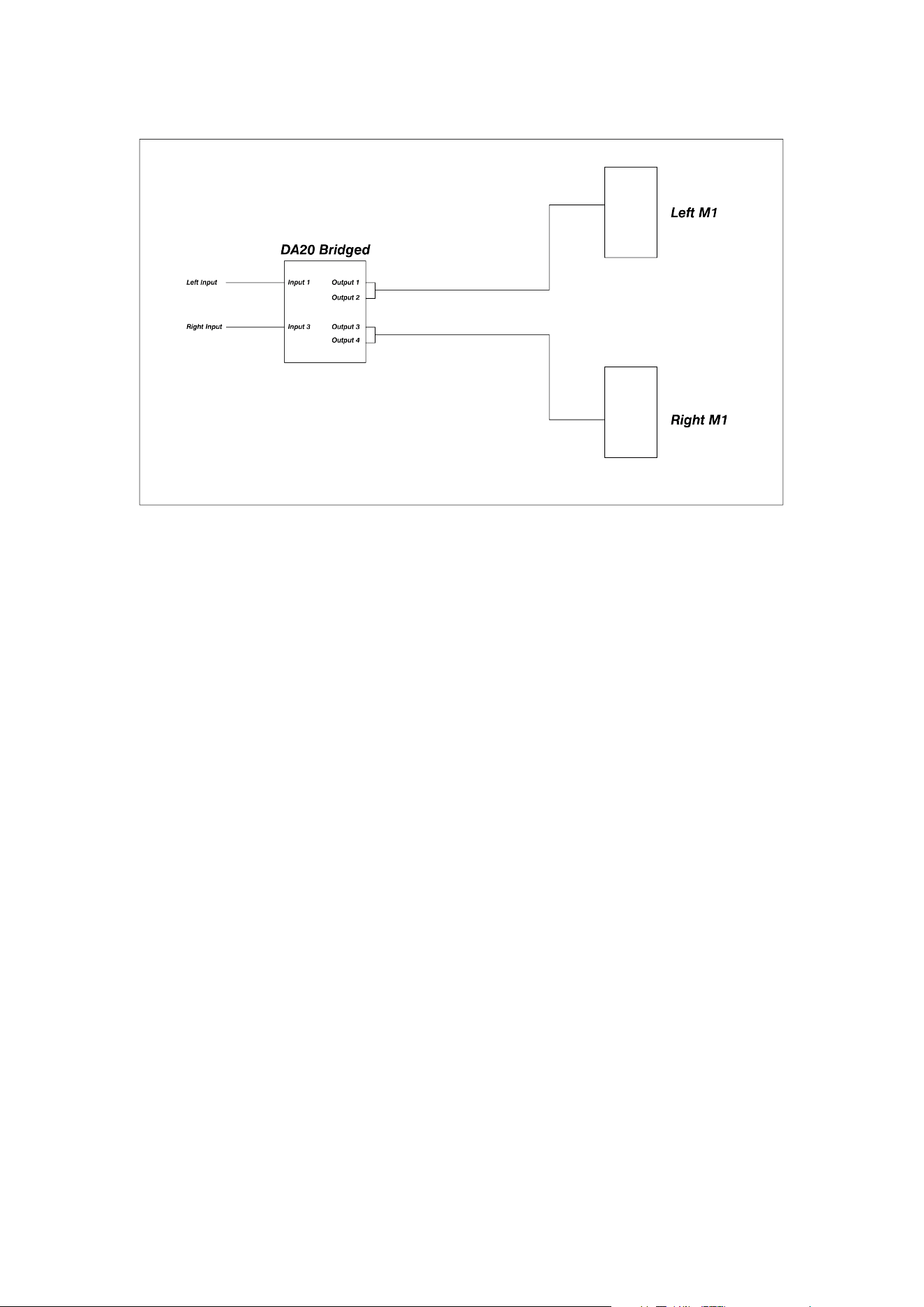
Figure 2b: Typical Stereo M1 MkII system with bridged Delta 20 amplifier
8 M1 MkII Owner’s Manual

3.2: Positioning
The M1 MkII loudspeaker is intended to be stand-mounted just in front of the mixing console/workstation. It can
be mounted on the console meter bridge if suitably substantial shelves are available. It can also be flush-mounted
into a wall, in which case the low-frequency output will be increased.
The optimum distance from the speaker to the listener is typically in the range of 1 to 3 meters.
The acoustic centre of the M1 MkII is midway between the centres of the two bass units. This point should be
angled towards the mixing position, both horizontally and vertically, to ensure the ecient acoustical summing of
all the drivers.
If the studio is seeking approval and licensing from Dolby, THX or a similar entity, then these parties or qualified
acoustic consultants should be consulted prior to installation, so that their specific requirements can be met.
If the M1 MkII is to be used behind a screen, then a woven, acoustically transparent screen must be used. These
introduce very small amounts of acoustic attenuation at high frequencies.
Orientation
The illustration below demonstrates the optimum speaker orientation for a stereo M1 MkII system.
The M1 MkII cabinets should subtend at an angle of 60 degrees from the mix position to form an equilateral
triangle between the two loudspeakers and the mix position. The distance between the mix position and each M1
MkII should be no less than 1m to ensure correct acoustical summing of drivers.
Setout is based on the speaker acoustic centre (midway between the centres of the two bass units).
The cabinets should be set at a height such that all drivers have a clear path to the listening position, with no
screens or other obstructions in the way. This may require tilting the speaker to aim the acoustic centre of the M1
MkII directly at the mix position.
The aiming point at the mix position is typically 1.2m o the floor, but this can be varied to suit individual users.
Dolby Atmos HE guidelines recommend a listening height of 1.2 m.
3: Installation 9
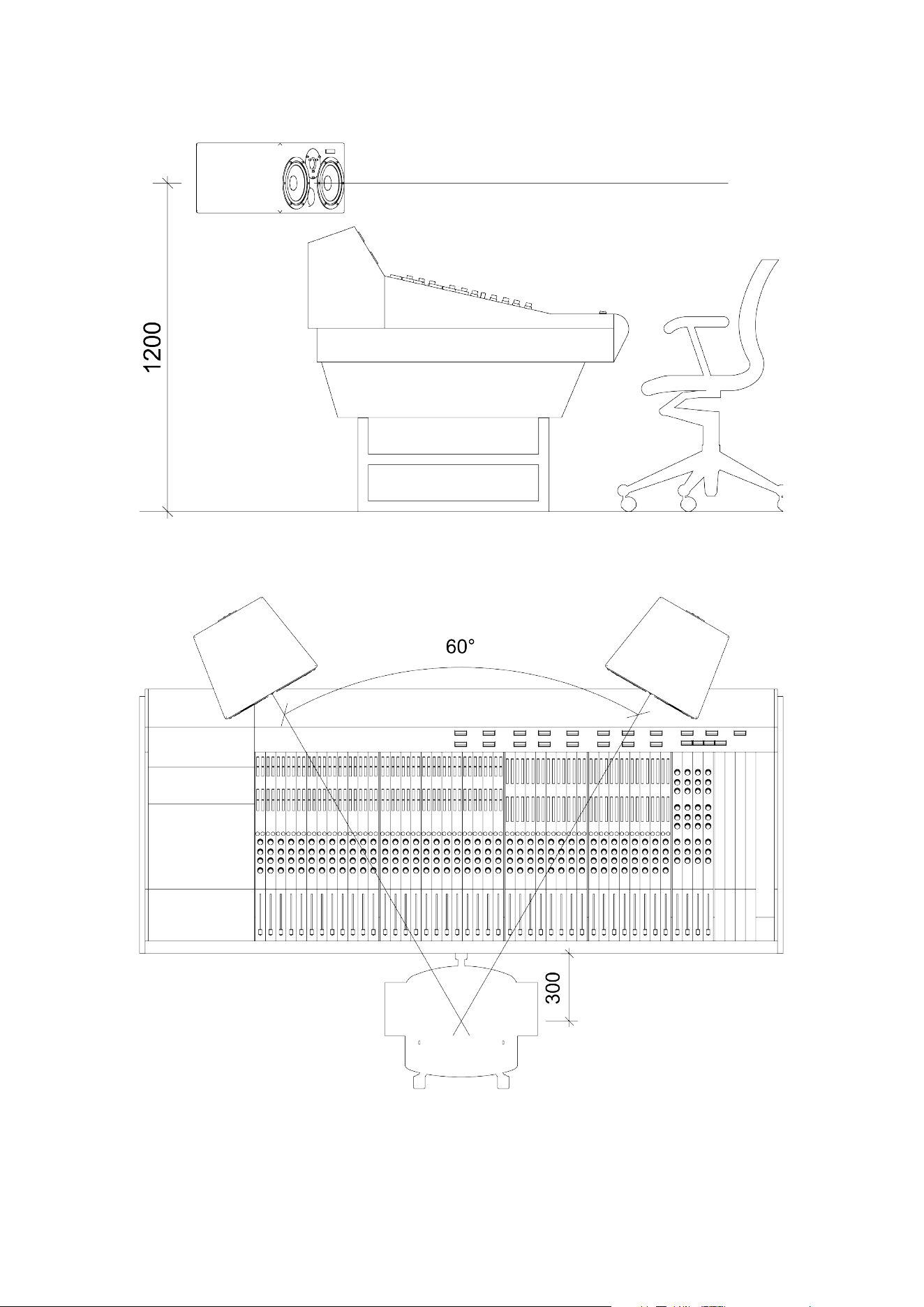
Figure 3a: Typical Stereo M1 MkII layout – side view
Figure 3b: Typical Stereo M1 MkII layout – top view
10 M1 MkII Owner’s Manual

4: Setting up and
adjusting
4: Setting up and adjusting 11

4.1: First time power up with DA2 or
DCA800/1400
Check that the system has been wired and set up according to the previous instructions, then simply switch on
the amplifier. Check for any hum or buzz, then play some music into the system at a low level. Verify that routing
and phasing are correct, then increase the level to a moderate level.
12 M1 MkII Owner’s Manual

4.2: Running in
Running in is essential before any judgments are passed or the system is subjected to the maximum level. Failure
to observe this can permanently damage the drivers, resulting in degraded performance for the system’s lifetime.
The easiest way to run a system in is to set the level controls roughly by ear as above, then connect a continuous
music source (eg, a CD player in repeat mode) and leave it to run for at least 12 hours at medium volume levels.
This will achieve a minimum of running in. The system will be run in fully after 5 to 6 days of continuous use. Note
that if the system is left unused for a period of time (days), it may take a few minutes to return to normal
performance after being switched on.
4: Setting up and adjusting 13

4.3: Testing and alignment
Once the system is suciently operational, it can be properly aligned. Dynaudio Acoustics strongly recommends
that the final setup and alignment be carried out by a qualified engineer with extensive expertise in acoustics and
the use of the appropriate test equipment that is required to align the M1 MkII system. Please contact our in-
house technical support team if you require any assistance.
In any room, various room eects will corrupt the perfectly flat response available from the M1 MkII, although it
should be possible to get a reasonably good response. If serious dips, peaks or notches are visible in the
frequency response, the room may require specific acoustic treatment by a reputable acoustic consultant. It may
be possible to fix some anomalies in the response using outboard equalisation upstream of the amplifier.
System Gain/Level Calibration
In the case of the DA2 amplifier, there is no gain adjustment, so gain is controlled by the console, preamp, or
DAW upstream of the amplifier.
The DCA amplifiers do have level controls, which can be set in conjunction with the console, preamp, or DAW
level controls to provide a comfortable working range.
14 M1 MkII Owner’s Manual

5: Protection
The cones of the LF drivers will be seen to move during normal playback. However, if this gets to a point where
the curved rubber surround is straightening out, then driver damage is likely.
The passive crossover features a self-resetting fuse on the HF unit, providing some protection against long-term
overloading. It is a slow-reacting device, however, so it will not protect against high-level transients, pops, and
thumps.
If the HF unit stops working, turn the level down to its lowest setting, then wait for a while. If the fuse has operated,
it should come back on.
If audible distortion is heard, this is a good sign that the speaker and/or amplifier is being overdriven. Turn it down.
5: Protection 15

6: Care and
Maintenance
High-quality components are used in the M1 MkII, which should provide a long, trouble-free life. Here are a few
hints to help them on their way.
▪ Never touch the drive units, especially the tweeter, which is very easily damaged. If the speakers are being
moved or work is going on nearby, replace the plastic tweeter protection domes that came with the
system.
▪ Avoid running the system into clipping or distortion. The amplifiers have clipping indicators on their front
panels. When an amplifier clips, it can send potentially damaging DC components to the drive units. They
may not fail immediately, but prolonged exposure to this will ultimately lead to failure. Set limiters to prevent
this from occurring.
▪ Avoid unplugging or switching o any equipment that is connected to the monitor system without first
muting the crossovers or switching o the amplifiers. Large spikes are often generated when equipment is
switched o, which will be amplified to a potentially damaging level.
▪ The amplifier power suggested for the M1 MkII is specified at a level to oer the best possible reproduction
of dynamics and short-term transients, and as such is capable of damaging the system if run continuously
at high levels.
▪ The very low distortion of these monitors means that it is easy to reach high SPLs without realising it. This
can be potentially damaging to both the monitors and the user’s ears. Take care of your monitoring levels.
16 M1 MkII Owner’s Manual

7: Servicing & Spare
parts
Drive units have been designed with easy replacement in mind. In the unlikely event that a replacement is required
for any of these parts, contact your dealer. They will supply you with the appropriate Dynaudio Acoustics spare
parts.
M1 MkII spare part numbers Contents
DA 81909 Single tweeter
DA 84073 Single bass driver
Please quote these references when ordering spares.
If you have trouble obtaining parts from your local dealer, don’t hesitate to get in touch with the Dynaudio service
centre:
https://dynaudio.com/faq/kb-tickets/new
Do not send any goods directly. Always contact us first.
WARRANTY
This product is guaranteed against defects in materials and workmanship for 2 years from the date of purchase.
This warranty is void if the unit has been tampered with or modified in any way, or in our opinion, has not been
used in accordance with the instructions above.
7: Servicing & Spare parts 17

8: Technical
Specifications
Size 256 (H) × 476 (W) × 393 (D) mm
Drivers 2 × Dynaudio 17 cm MSP Bass (6.5 inch)
- 1 × Dynaudio Esotar 3 Tweeter (1 inch)
Impedance 4 ohm
Connectors 4 mm Binding Posts as standard (Options Available)
Crossover
The system uses a high-eciency passive network with a
crossover frequency of 1650 Hz
Amplification
Amplifiers of 200 W to 500 W/ch – 4 ohm would normally be
specified.
Frequency response 45 Hz to 20 kHz (±3 dB, room dependent)
Typical peak SPL 122 dB @ 2 m, 2 cabinets driven
T.H.D. less than 1% at 90 dB
Weight 14 kg
↻ 2025-11-28
18 M1 MkII Owner’s Manual