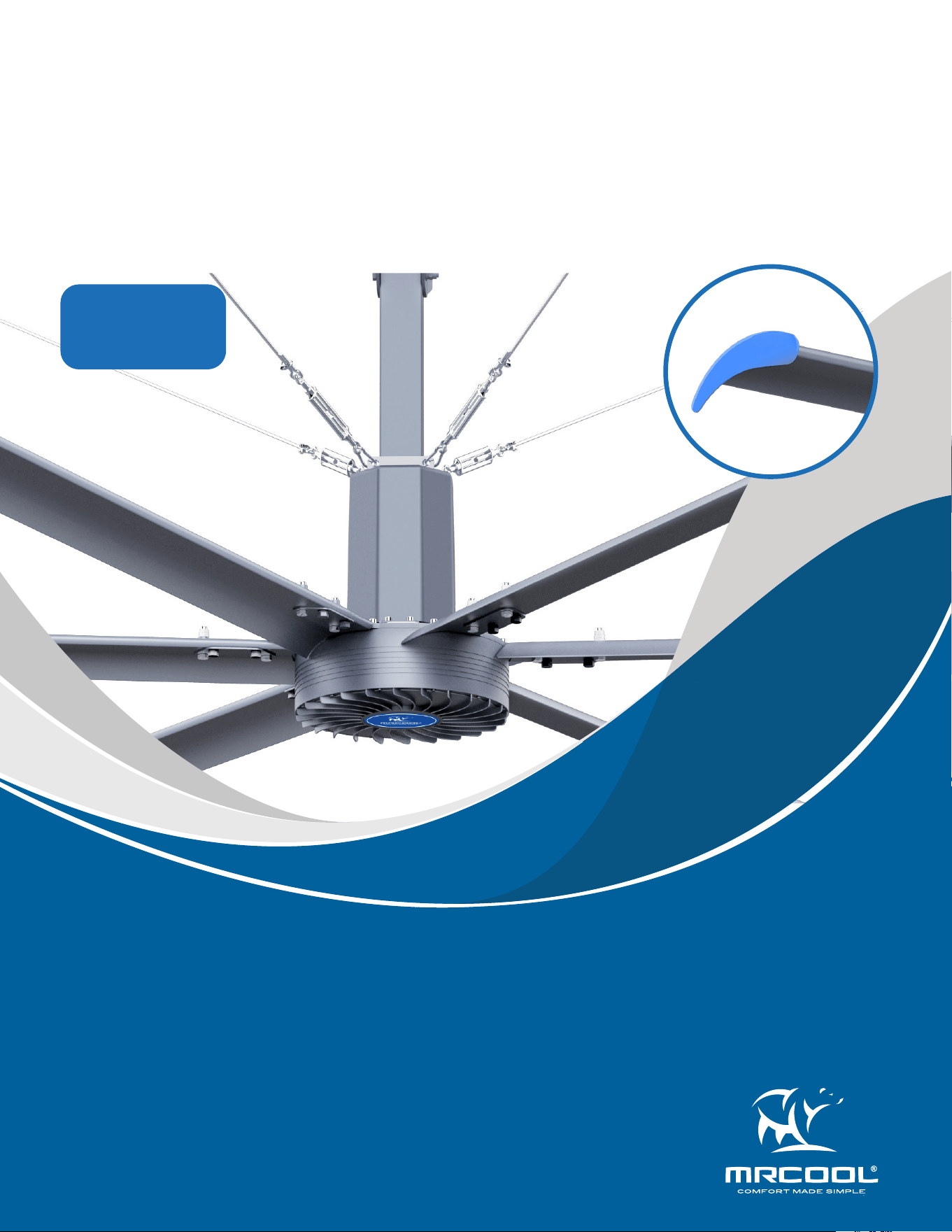
Industrial HVLS Fan
Installation &
Owner’s Manual
Read this manual carefully before installation and keep it where
the operator can easily nd it for future reference.
Due to updates and constantly improving performance, the
information and instructions within this manual are subject to
change without notice.
Version Date: 10/23/2024
Please visit www.mrcool.com/documentation
to ensure you have the latest version of this manual.
MODELS:
MCFAN16PBGR
MCFAN24XBGR
mrcool.com1
CONTENTS
SAFETY PRECAUTIONS ..................................................................................................... 1
UNIT OVERVIEW ................................................................................................................ 2
2.1 Product Summary ................................................................................................ 2
2.2 Technical Parameters ........................................................................................ 2
2.3 Installation Data .................................................................................................. 2
2.4 Exploded View Unit Diagrams ............................................................................ 3
2.5 Packing Lists ......................................................................................................... 4
16-FOOT FAN INSTALLATION .......................................................................................... 6
24-FOOT FAN INSTALLATION ........................................................................................ 11
CONTROL PANEL OPERATION ...................................................................................... 17
TROUBLESHOOTING ...................................................................................................... 18
1
2
3
4
5
Contents
6
Incorrect usage may cause serious damage or injury.
The symbols below are used throughout this manual to indicate instructions that should be followed closely
or actions that should be avoided to prevent death, injury, and/or property damage.
Safety Precautions
Read Before Using
CAUTION
Indicates the possibility of
personal injury or loss of life.
Indicates the possibility of
property damage or serious
consequences.
WARNING
WARNING
1. Read this manual carefully before installation in order to prevent potential damage or injury.
2. Nonprofessionals are not allowed to repair, inspect, or replace parts.
3. In order to reduce the risk of electric shock, do not carry out wiring work within 1 minute of switching the power on or
o. (The capacitor will also retain power for a short time after power is switched o.)
4. When replacing or moving the power supply, cut o the power and wait for all indicators to be o for 1 minute before
operation.
5. If there is unusual oscillating movement, immediately stop the ceiling fan and contact MRCOOL, or a qualied service
professional. The means of attachment to the ceiling, such as hooks or other devices, must be xed with a sucient
strength to withstand 4 times the weight of the ceiling fan.
CAUTION
1. Use the correct controller according to the product model. Do not use an unmatched controller, which may cause
damage to the motor or controller.
2. Conrm whether the power is connected according to the marks and that there is no obstacle within the operating
range of the product before operation.
3. After operation, check whether the rotation direction of the product is correct (clockwise, when viewed from below).
4. This product should not be operated in freezing, corrosive, explosive, and severely dusty environment.
5. The installation and maintenance must be carried out by professionally trained or experienced personnel with
electrical certications.
mrcool.com 2
2
UNIT OVERVIEW
2
2.1 Product Summary
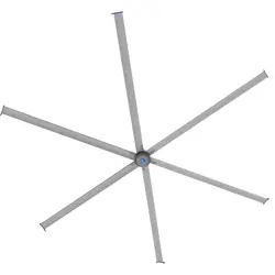
The MRCOOL® Industrial HVLS fan with permanent magnet frequency conversion is specically developed to
save energy, reduce consumption, and create a comfortable work environment. The independently designed
permanent magnet motor features a small, light weight size, high eciency, low noise, and variable frequency
speed regulation. This new type of ceiling fan is widely used in industrial plants, logistics warehouses, waiting
rooms, exhibition halls, gyms, and supermarkets for both ventilation and cooling. The fan can produce a large
amount of airow to create eective overall air circulation.
2.2 Technical Parameters
MCFAN16PBGR MCFAN24XBGR
Diameter-ft (m) 16 (5) 24 (7.3)
Power (kW) 0.75 1.5
Voltage (V) 1PH 220-240 1PH 220-240
Frequency (Hz) 50/60 50/60
Air Volume (m
3
/min) 10000 15500
Rotating Speed (rpm) 80 60
Number of Blades (Pcs)
5 6
Noise (dB(A)) 38 38
Motor Weight (kg) 22 42
Fan Weight (kg) 62 113
Coverage Area-ft
2
(m
2
) 1640 (500) 5577 (1700)
Mounting Bracket I-beam/square steel/concrete I-beam/square steel/concrete
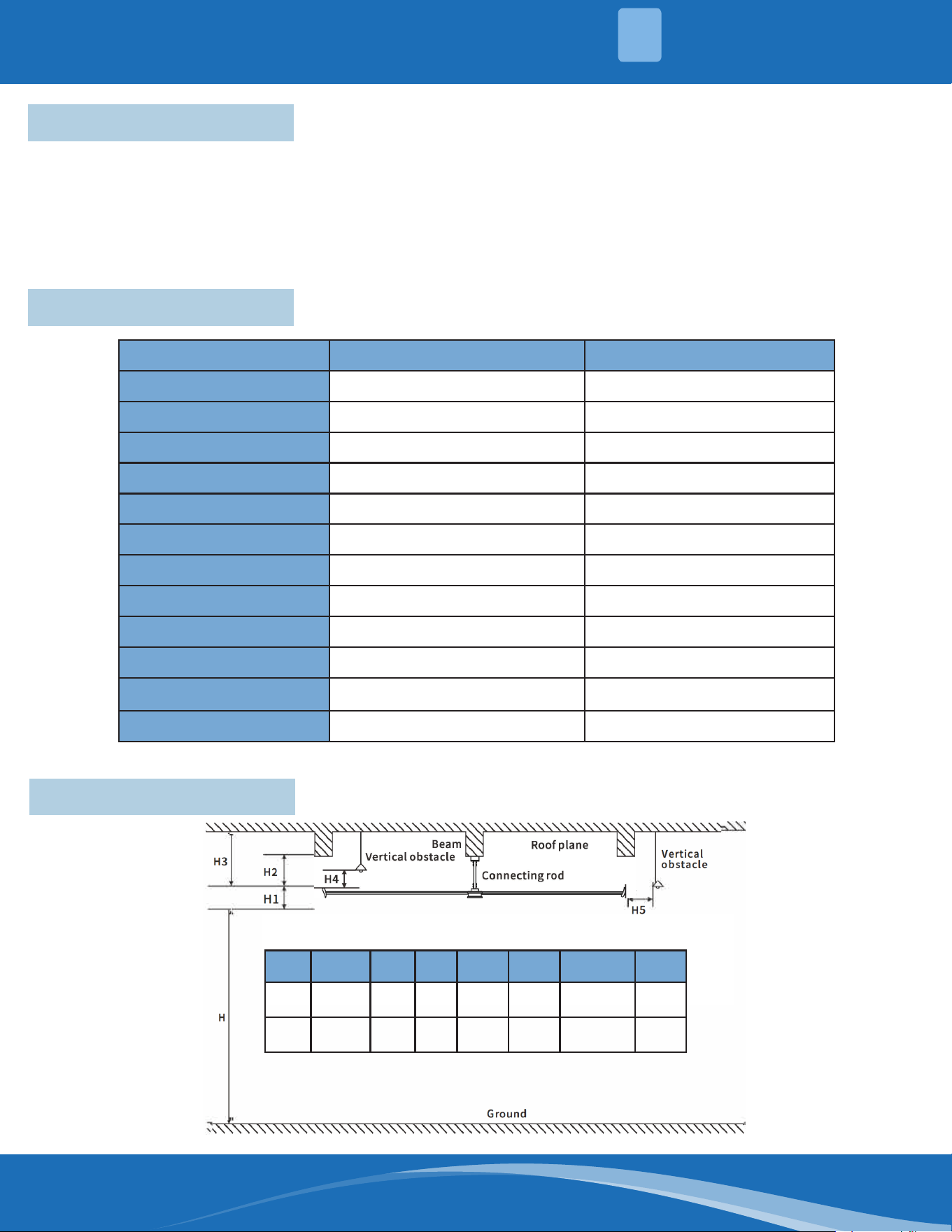
2.3 Installation Data
Specs. H H1 H2 H3 H4
Connecting
Rod
H5
16 ft
(5m)
11.8-19.7
(3.6-6)
0.49
(0.15)
≥0.98
(≥0.3)
≥1.9
(≥0.6m)
≥0.98
(≥0.3m)
1.9-6.6
(0.6-2m)
0.66
(≥0.2m)
24 ft
(7.3m)
16.4-39.3
(5-12)
0.66
(0.2m)
≥0.98
(≥0.3)
≥2.62
(≥0.8m)
≥0.98
(≥0.3m)
1.9-16.4
0.6-5m
0.66
(≥0.2m)
mrcool.com3
UNIT OVERVIEW
2
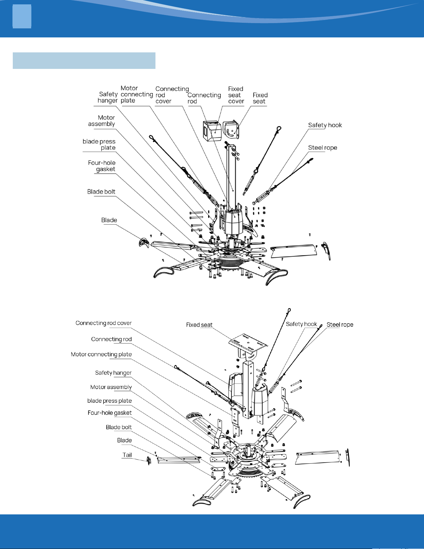
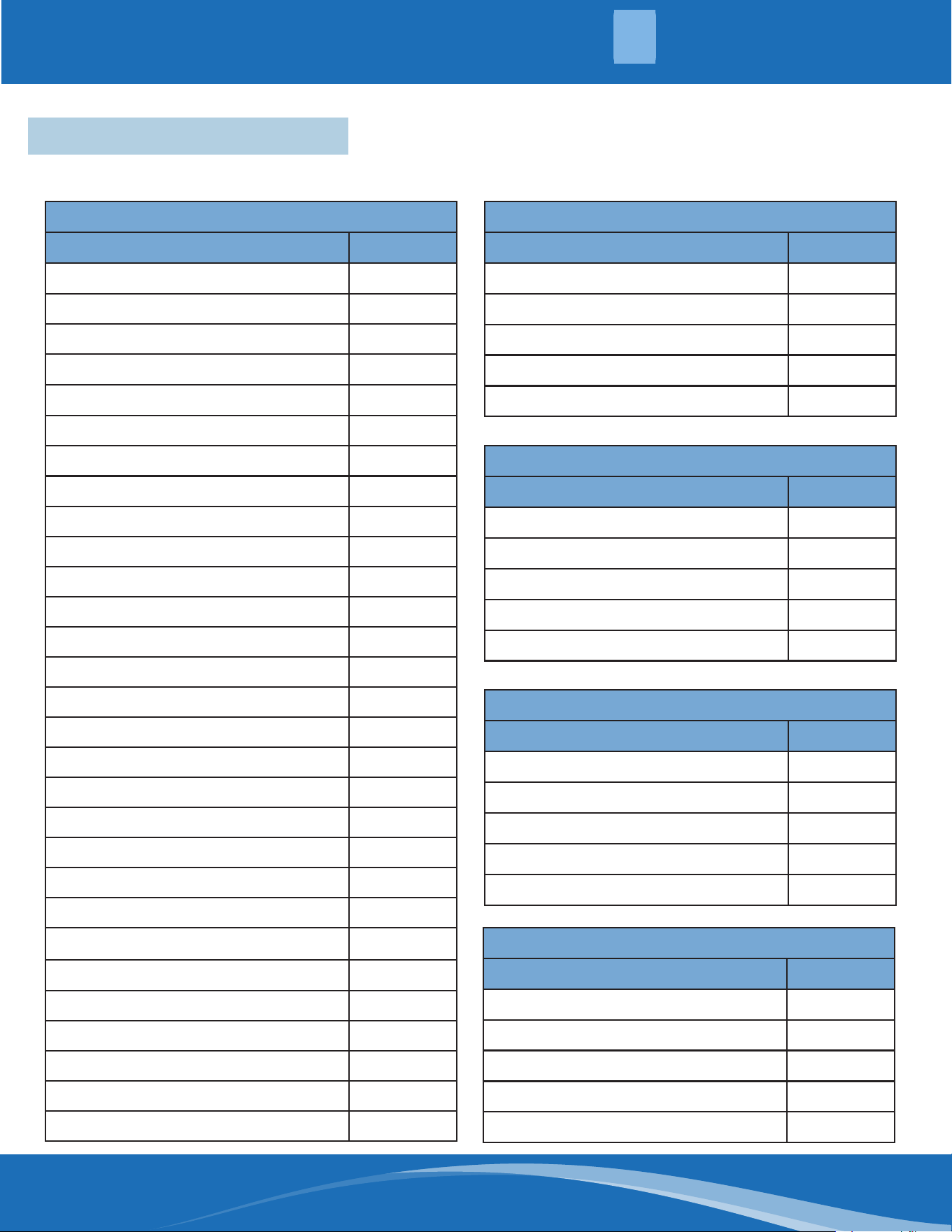
2.4 Exploded View Unit Diagrams
MCFAN16PBGR
MCFAN24XBGR
mrcool.com 4
4
UNIT OVERVIEW
2
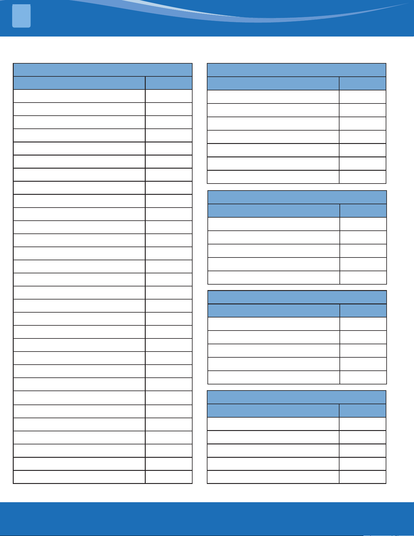
2.5 Packing Lists
MCFAN16PBGR
General Accessories
Name Quantity
Motor
1
Controller 1
M12x50 Hex Bolt (Full Thread) 10
M12x16 Hex Bolt (Full Thread)
10
M12 Hex Nylon Nut
10
Φ12 Standard Spring Washer 20
Four-Hole Gasket 5
Blade 5
Blade Press Plate 5
Tail Wing 5
M5*10 Self-Tapping Screw 10
60*60 Connecting Rod 1
6-6 Quick-Connect Terminal 1
M3*16 Philip's Head Screw 2
Connecting Rod Cover 2
M4*12 Cross Stainless Steel Screw 6
Motor Connecting Plate 2
Safety Hanger 2
M10x100 Hex Bolt 4
M10x80 Hex Bolt 2
Φ10 Flat Washer 12
Φ10 Spring Washer 6
M10 Hex Nylon Nut 6
Φ6 Steel Rope
1
M6 Slide Retainer 18
M8 Turnbuckles Hook 4
Locking Pin 4
16AWG*4 Cable 20
18AWG*2 Cable 20
Concrete Structure
Name Quantity
RC Structure 1
Fixed Base Cover 1
M12x100 Expansion Screw 4
M12x100 Expansion Screw Hook 2
4*10 Knurled Hand Screw 2
I-Shaped Steel Structure
Name Quantity
Press Plate 2
M10X60 Hex Bolt (Full Thread) 4
Ø10 Large Washer
8
Ø10 Spring Washer
4
M10 Hex Nylon Nut
4
Square Steel Structure
Name Quantity
Press Plate 1
M10X150 Hex Bolt (Full Thread) 4
Ø10 Large Washer 8
Ø10 Spring Washer 4
M10 Hex Nylon Nut 4
Installation Tools
Name Quantity
13-16 Open End Wrench 2
14-17 Open End Wrench 2
Cross Screwdriver 1
Slotted Screwdriver 1
5mm Inner Hex Spanner 1
mrcool.com5
UNIT OVERVIEW
2
MCFAN24XBGR
Concrete Structure
Name Quantity
L-Plate 2pcs/set 2
M12X45 Hex Bolt (full thread) 4
Ø12 Large Washer 8
Ø12 Spring Washer 4
M12 Hex Nylon Nut 4
M12x100 Expansion Screw 10
M12x100 Expansion Screw Hook 4
I-Shaped Steel Structure
Name Quantity
Press Plate 2
M12X60 Hex Bolt (Full Thread) 4
Ø12 Large Washer
8
Ø12 Spring Washer
4
M12 Hex Nylon Nut
4
Square Steel Structure
Name Quantity
Press Plate 1
M12x160 Hex Bolt (Full Thread) 4
Ø12 Large Washer 8
Ø12 Spring Washer 4
M12 Hex Nylon Nut 4
Installation Tools
Name Quantity
13-16 Open End Wrench 2
14-17 Open End Wrench 2
Cross Screwdriver 1
Slotted Screwdriver 1
5mm Inner Hex Spanner 1
General Accessories
Name Quantity
Motor 1
Controller 1
M12x50 Hex Bolt (Full Thread) 12
M12x16 Hex Bolt (Full Thread) 12
M12 Hex Nylon Nut 12
Φ12 Standard Spring Washer 24
Four-Hole Gasket 6
Blade 6
Blade Press Plate 6
Tail Wing 6
M5*10 Self-Tapping Screw 12
80*80 Connecting Rod 1
6-6 Quick-Connect Terminal 1
M3*16 Philip's Head Screw 2
Connecting Rod Cover 2
M4*12 Cross Stainless Steel Screw 6
Motor Connecting Plate 2
Safety Hanger 2
M12x140 Hex Bolt 2
M12x130 Hex Bolt 2
M12x100 Hex Bolt 2
Φ12 Flat Washer 12
Φ12 Spring Washer 6
M12 Hex Nylon Nut 6
Φ6 Steel Rope 1
M6 Slide Retainer 18
M10 Turnbuckles Hook 4
Locking Pin 4
14AWG*4 Cable 30
18AWG*2 Cable 30
mrcool.com 6
6
16-FT FAN INSTALLATION
3
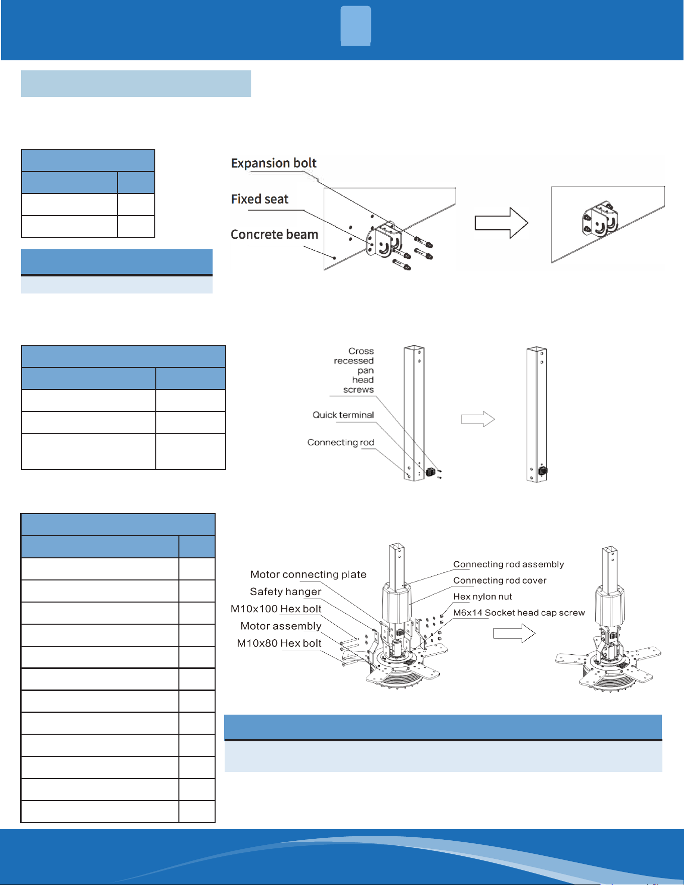
Step 1:
Determine the installation position of the fan, and mark it with the xed seat. Drill the mounting hole with a 12mm
drill bit (hole depth >3.15" (80mm)), then install the M10X80 expansion bolts to secure the xed seat.
Accessories Needed:
Name Qty.
Fixed Seat 1
Expansion Bolt 4
NOTE
Install expansion bolts securely.
Step 3:
Install the connecting rod on the motor and screw it without tightening.
Accessories Needed:
Name Qty.
Motor Assembly 1
Connecting Rod Assembly 1
Motor Connecting Plate 2
Safety Hanger 2
Connecting Rod Cover 1
M5X10 Slotted Screw 2
M6X14 Hex Bolt 4
M10X100 Hex Bolt 2
M10X80 Hex Bolt 2
M10 Hex Nylon Nut 4
Ø10 Large Washer 8
Ø10 Spring Washer 4
NOTE
Ensure the blade bracket on the motor assembly is installed in the correct
direction. (See the gure above.)
3 - 16 ft. Fan Installation Steps
Step 2:
Install the quick terminal on the connecting rod, screw and lock it tightly.
Accessories Needed:
Name Qty.
Connecting Rod 1
Quick Terminal 1
Cross Recessed Pan
Head Screws M3x16
2
mrcool.com7
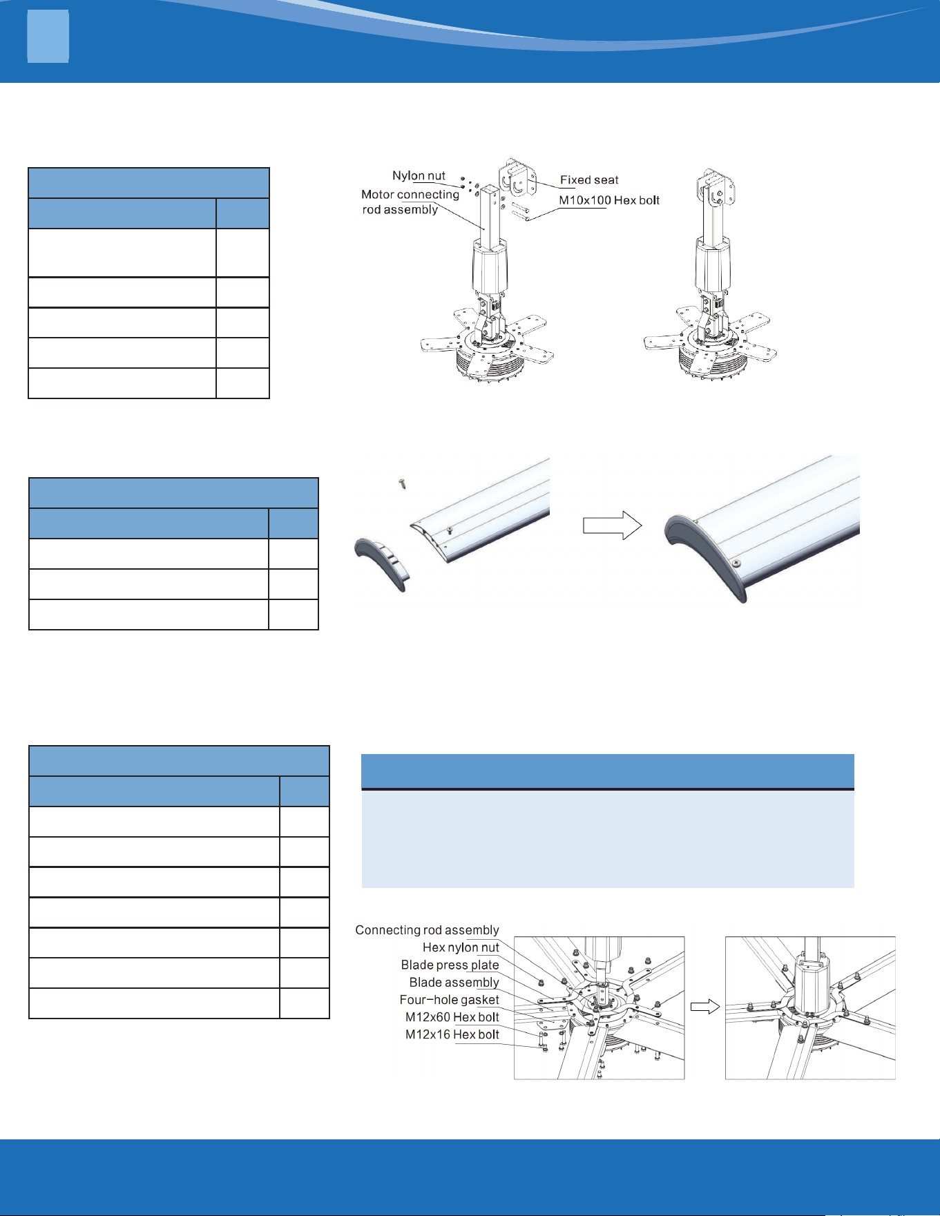
Step 5:
Install the blade tail on the blade and lock it.
Accessories Needed:
Name Qty.
Blade 5
Tail plane 5
ST4.8X10 Self Tapping Screw 10
Step 6:
Install the tail blade assembly on the motor. Install the screws and pull the blade outward from the center of the
motor. Install the blade screws without tightening.
Accessories Needed:
Name Qty.
Blade Assembly 5
Four-Hole Gasket 5
Blade Press Plate 5
M12X50Hex Bolt (Full Thread) 10
M12X16 Hex Bolt (Full Thread) 10
M12 Hex Nylon Nut 10
Ø12 Spring Washer 20
NOTE
Before tightening the fan blade screws, pull the blade
outward from the center of the motor. Adjust the levelness
of the motor and the verticality of the connecting rod before
tightening the screws and check whether all the screws are
tightened.
16-FT FAN INSTALLATION
3
Accessories Needed:
Name Qty.
Motor Connecting
Rod Assembly
1
M10X100 Hex Bolt 2
M10 Hex Nylon Nut 2
Ø10 Large Washer 4
Ø Spring Washer 2
Step 4:
Install the connecting rod motor assembly on the xed seat and screw it without tightening.
mrcool.com 8
8
Step 7:
Adjust the levelness of the motor and the verticality of the connecting rod, tighten the connecting rod and blade
screws, install the xed base cover and tighten the screws.
NOTE
Before tightening the fan blade screws, pull the blade outward from the
center of the motor. Adjust the levelness of the motor and the verticality
of the connecting rod before tightening the screws and check whether all
the screws are tightened.
16-FT FAN INSTALLATION
3
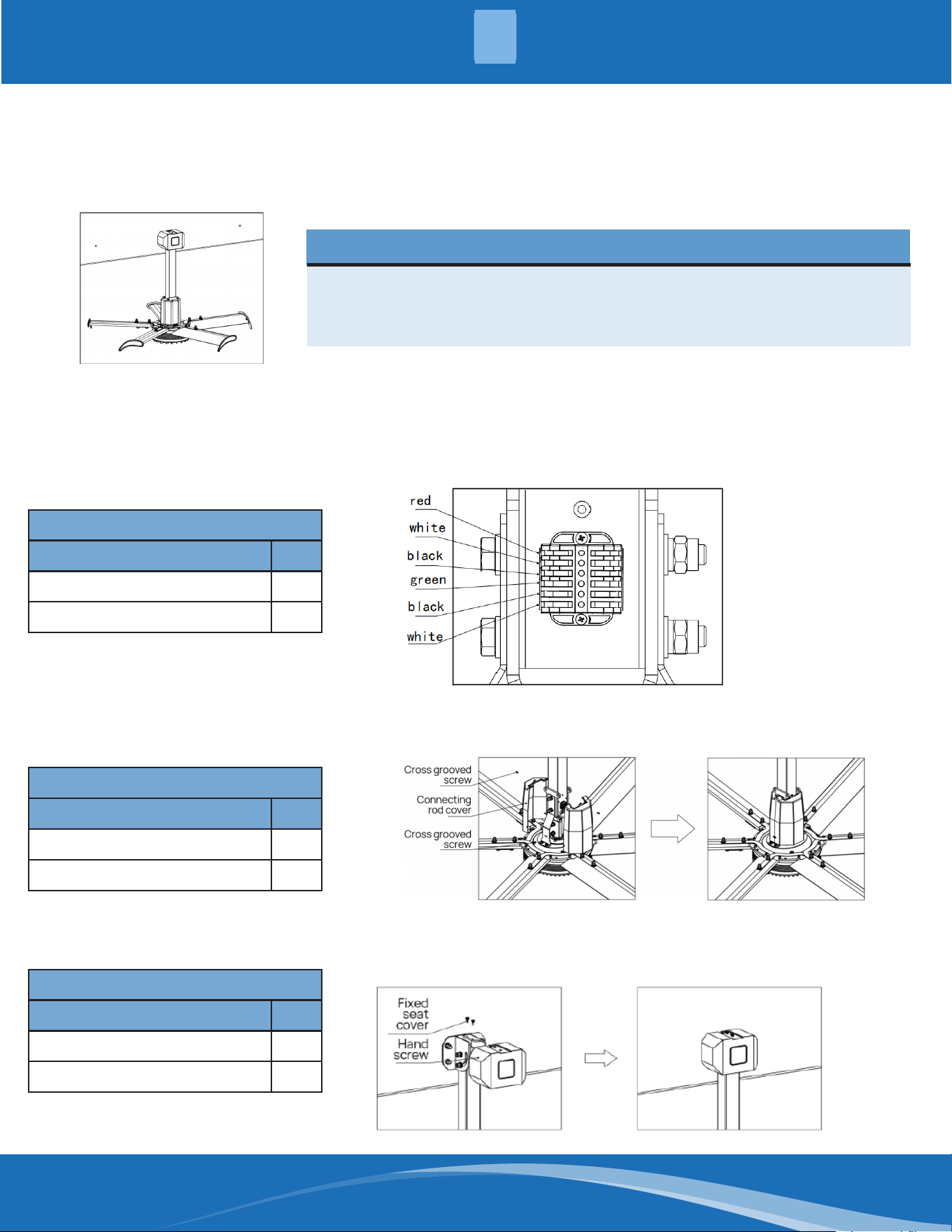
Step 8:
Arrange the power cable from the ceiling fan to the controller, and insert the motor lead wire and the fanpower
cable into the wiring clip: From bottom to top red, white, black, green, black, white.
Accessories Needed:
Name Qty.
Cable 12AWGX4X20m 1
Cable18AWGX2X20M 1
Step 9:
Install the connecting rod cover, screw and lock it as shown.
Accessories Needed:
Name Qty.
Connecting Rod Cover 2
M4X12 Cross Screw 6
Step 10:
Install the xed seat cover as shown and lock it with the head screw.
Accessories Needed:
Name Qty.
Fixed Seat Cover 1
Hand Screw M4 2
mrcool.com9
16-FT FAN INSTALLATION
3
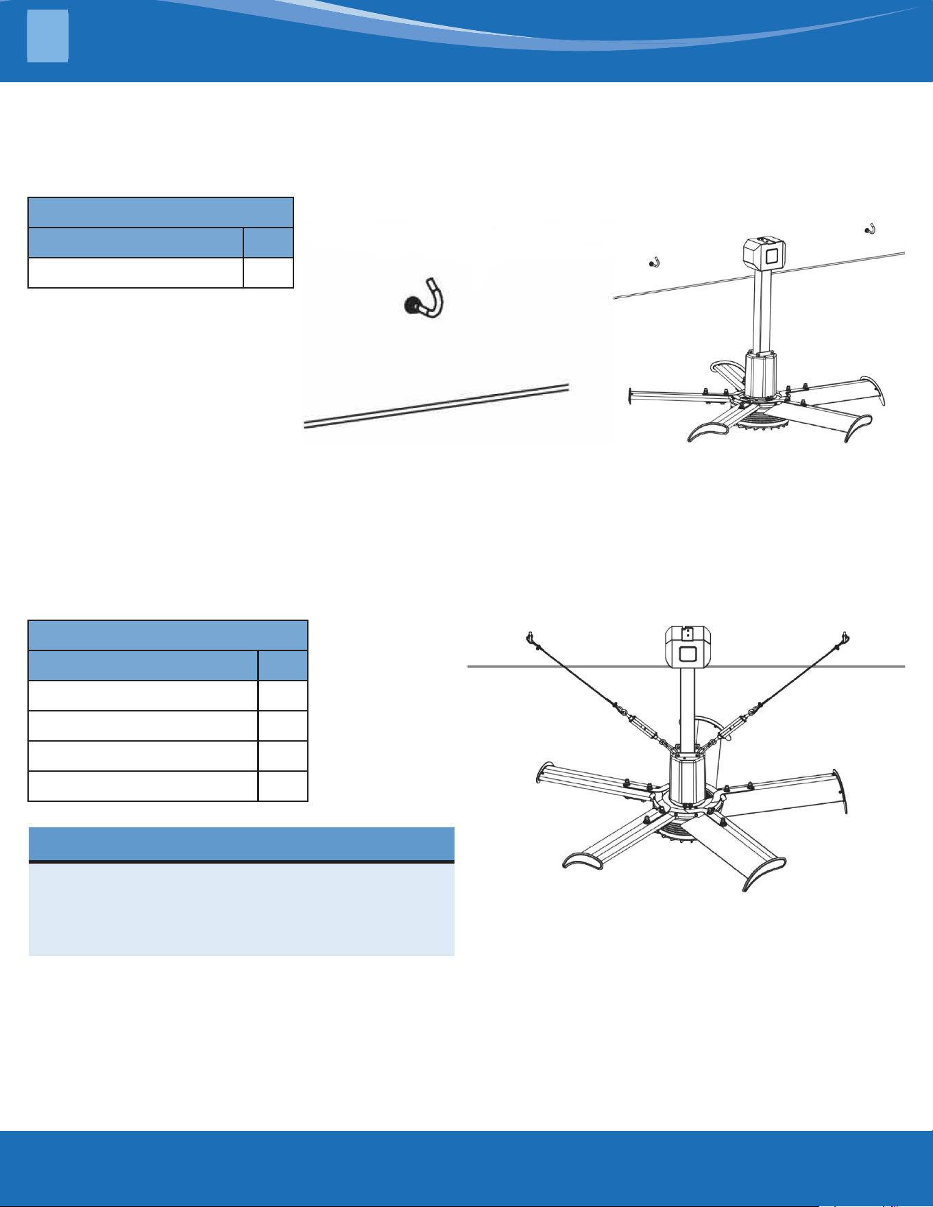
NOTE
The included angle between the steel rope and the
connecting rod is greater than 30° and less than 45°.
The steel rope clamp shall be securely installed and
the steel rope can be adjusted by the elastic hook.
Step 11:
Determine the position of the expansion bolt hook, drill the mounting hole with a 14mm drill bit (hole depth >
80mm), install the M12X100 expansion bolt hook with the opening upward and tighten the expansion screw hook.
Accessories Needed:
Name Qty.
Expansion Bolt Hook 4
Step 12:
Fix the steel rope on the elastic hook with the steel rope clamp and x the other end on the steel rope hook. Install
the hook on the connecting plate of the ceiling fan motor. One end of the steel rope is xed on the expansion
screw hook with the steel rope clamp and adjust the tension of the steel rope with the elastic hook (until the steel
rope is just straight).
Accessories Needed:
Name Qty.
M6 Steel Rope Clamp 8
30m Steel Rope 1
Elastic Hook 2
Steel Rope Hook 4
mrcool.com 10
10
16-FT FAN INSTALLATION
3
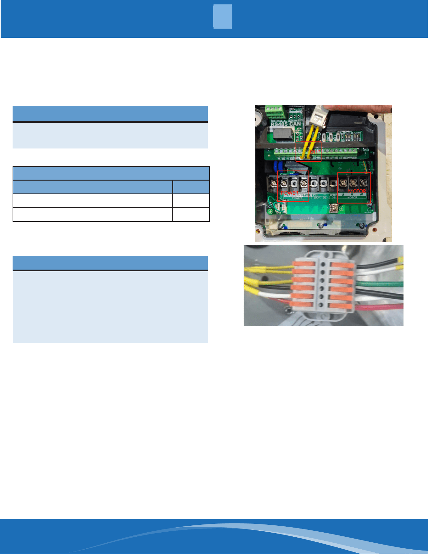
Step 13:
Select the location to install the controller. Connect the motor and the main power to the controller as required.
Check whether there are obstacles that would interfere with operation. Control the fan according to the operation
manual of the controller.
NOTE
The phase sequence of the motor connected to the
controller cannot be out of order.
Accessories Needed:
Name Qty.
Permanent Magnet Motor Controller 1
Rubber Sheathed Cable 2
NOTE
Do not connect the main power directly to the
ceiling fan. Conrm whether the power voltage
matches the controller voltage. After connecting the
wire, pull to verify that the wire is secured. When
connecting the fast terminal, the power cord should
be peeled 13/16" (10mm) and inserted into the card
slot as a depth of 5/8" (17mm).
mrcool.com11
4 - 24 ft. Fan Installation Steps
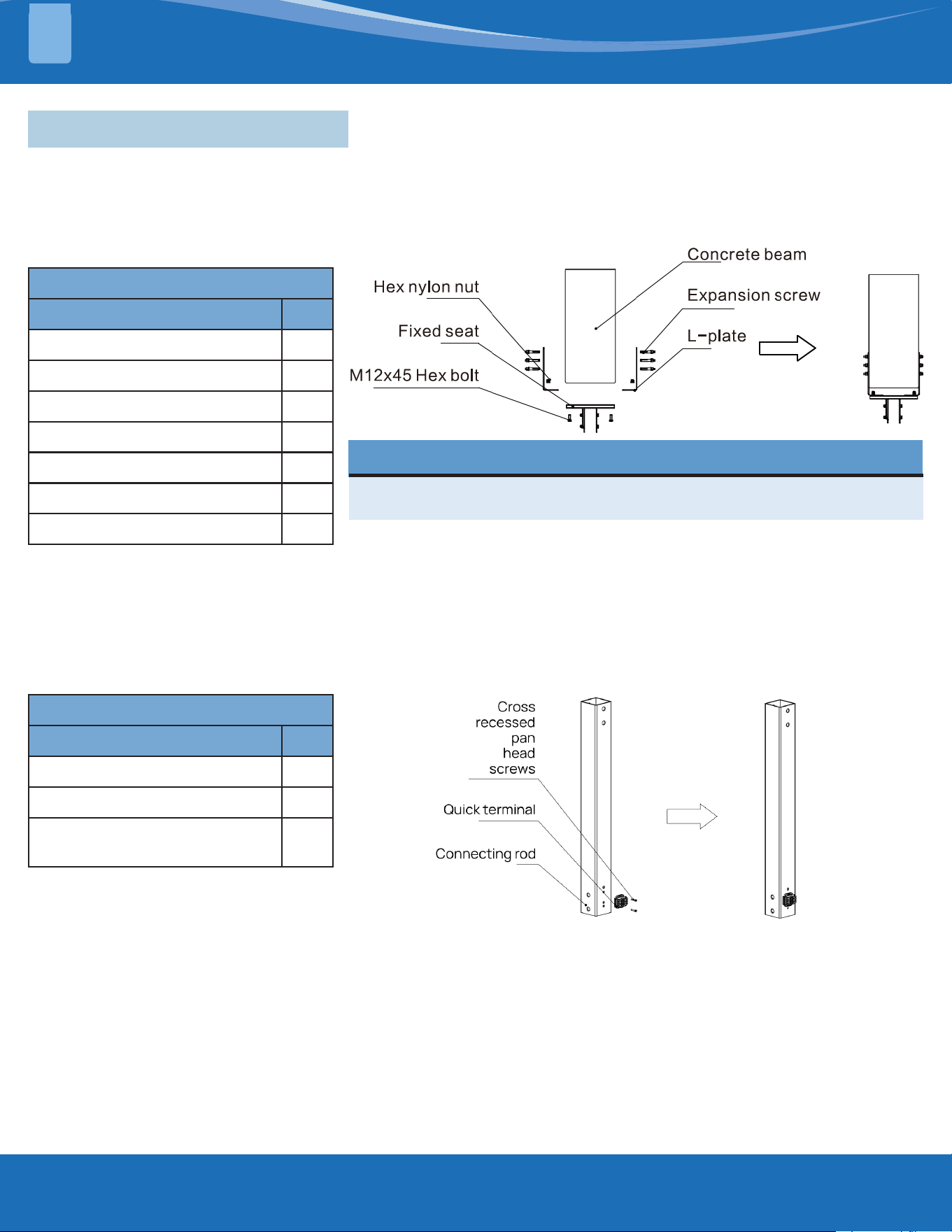
Step 1:
Determine the installation position of the ceiling fan, and mark it with the xed seat L-plate. Drill the mounting
hole with a 14mm drill bit (hole depth >80mm), install the M12X100 expansion screw, install the L-plate on the
expansion screw, adjust the levelness of the L-plate, tighten the expansion screw and install the xed seat under
the L-plate and tighten it.
Accessories Needed:
Name Qty.
Fixed Seat 1
L-Plate 2
M12X45 Hex Bolt (Full Thread) 4
Ø12 Large Washer 8
Ø12 Spring Washer 4
M12 Hex Nylon Nut 4
M12X100 Expansion Screw 10
NOTE
Both the L-plate and the xed seat shall be installed horizontally and
symmetrically at both ends.
24-FT FAN INSTALLATION
4
Step 2:
Install the quick terminal on the connecting rod, screw and lock it tightly.
Accessories Needed:
Name Qty.
Connecting Rod 1
Quick Terminal 1
Cross Recessed Pan Head
Screws M3x16
2
mrcool.com 12
12
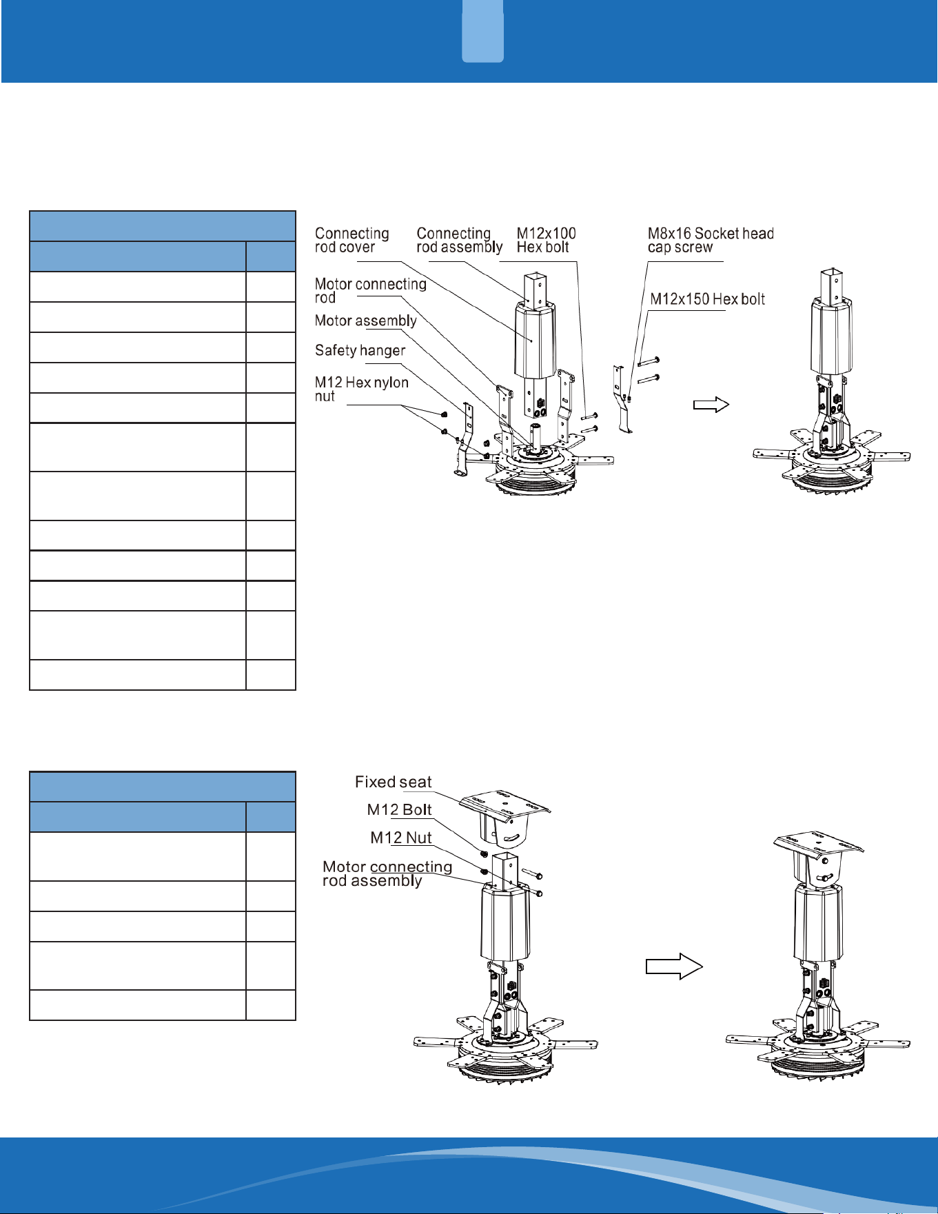
Step 3:
Install the connecting rod on the motor, install the connecting rod screws and safety hanger screws, and screw it
without tightening.
Accessories Needed:
Name Qty.
Motor Assembly 1
Connecting Rod Assembly 1
Motor Connecting Plate 2
Bracket Connecting Plate 2
Connecting Rod Cover 2
M5X10 Cross Recessed
Screw
2
M8X20 Socket Heat Cap
Screw
4
M12X150 Hex Bolt 2
M12X100 Hex Bolt 2
Ø12 Large Washer 8
Ø12 Standard Spring
Washer
4
M12X100 Hex Bolt 4
Step 4:
Install the mounted motor connecting rod assembly on the xed seat and screw it without tightening.
Accessories Needed:
Name Qty.
Motor Connecting Rod
Assembly
1
M12X130 Hex Bolt 2
Ø12 Large Washer 4
Ø12 Standard Spring
Washer
2
M12 Hex Nylon Nut 2
24-FT FAN INSTALLATION
4
mrcool.com13
24-FT FAN INSTALLATION
4
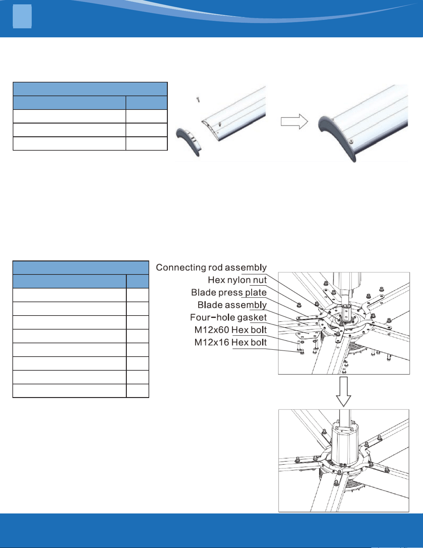
Step 6:
Install the tail blade assembly on the motor, install the screws and pull the blade outward from the center of the
motor. Screw the blade without tightening.
Accessories Needed:
Name Qty.
Blade Assembly 6
M12X50 Hex Bolt (Full Thread) 12
M12X16 Hex Bolt (Full Thread) 12
Blade Press Plate 6
Four-Hole Gasket 6
M12 Hex Bolt 12
Ø12 Spring Washer 24
Ø12 Flat Washer 12
Step 5:
Install the blade tail on the blade and lock it.
Accessories Needed:
Name Qty.
Blade 6
Tail Plane 6
ST4.8x16 Self Tapping Screw 12
mrcool.com 14
14
24-FT FAN INSTALLATION
4
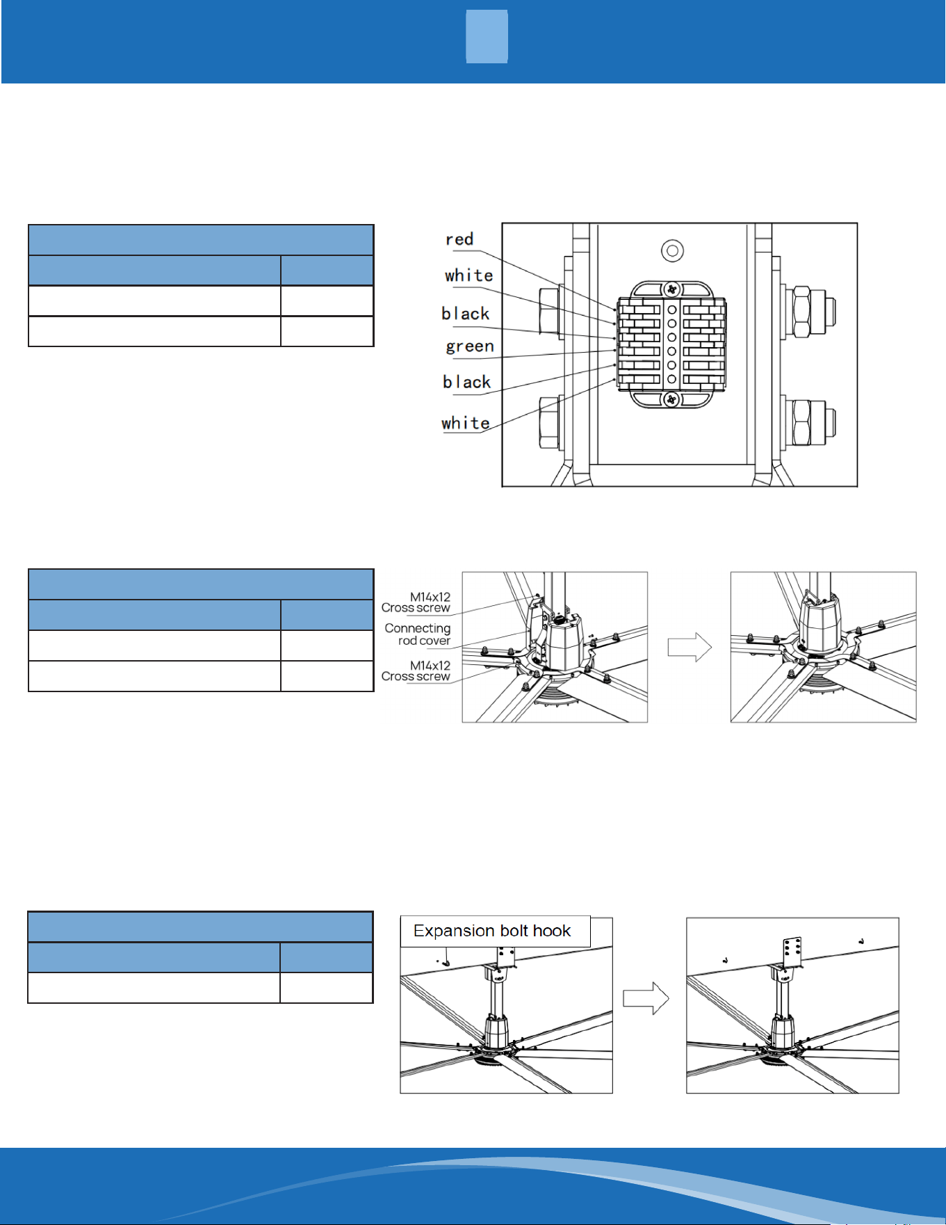
Step 8:
Install the connecting rod cover, screw and lock as shown below.
Step 7:
Arrange the wiring from the ceiling fan to the controller, insert the motor lead wire and the fan power wire into the
wiring clip. Arrange from bottom to top according to the diagram: red, white, black, green, black, white.
Accessories Needed:
Name Qty.
Cable14AWGX4X30M 1
Cable18AWGX2X30M
1
Accessories Needed:
Name Qty.
Connecting Rod Cover 2
M4X12 Cross Screw 6
Step 9:
Determine the position of the expansion bolt hook, drill the mounting hole with a 14mm drill bit (hole depth
80mm), install the M12X100 expansion bolt hook with the opening upward and tighten the expansion screw
hook.
Accessories Needed:
Name Qty.
Expansion Bolt Hook 4
mrcool.com15
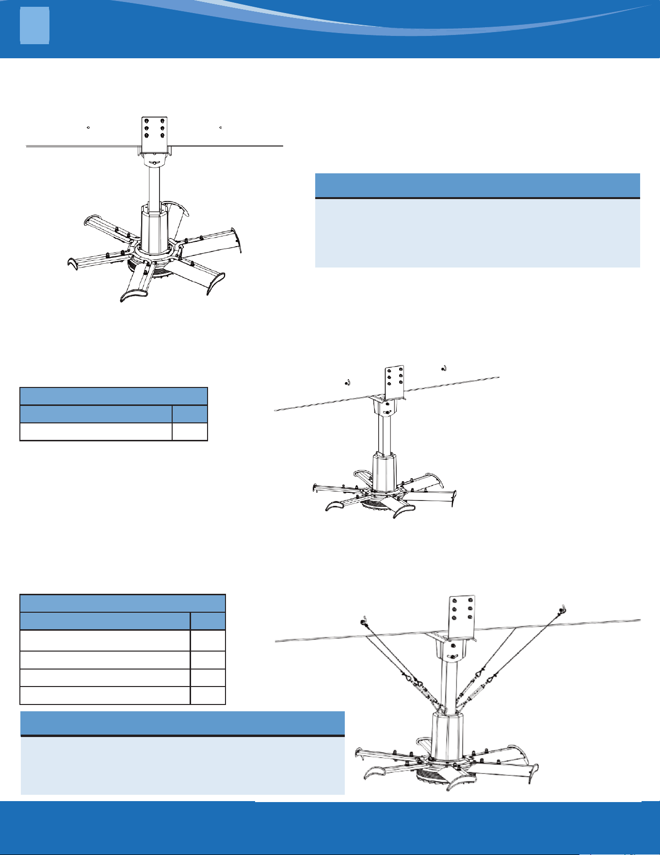
Step 10:
Adjust the levelness of the motor and the verticality of the connecting rod, tighten the connecting rod and blade
screws, install the xed seat cover, and tighten the screws.
NOTE
Before tightening the blade screws, pull the blade
outward from the center of the motor. Adjust the
levelness of the motor and the verticality of the
connecting rod before tightening the screws and check
whether all the screws are tightened.
Step 11:
Determine the position of the expansion screw hook, drill the mounting hole with a 14mm drill bit (hole depth
>80mm), install the M12X100 expansion screw hook with the opening upward and tighten the expansion screw
hook.
Accessories Needed:
Name Qty.
Expansion Screw Hook 4
Step 12:
Fix the steel rope on the O end of the turn buckle with the steel rope clamp. Install the end of the turn buckle on
the connecting plate of the fan motor, x the end of the steel rope on the expansion screw hook with the steel
rope clamp, and adjust the tightness of the steel rope with the turn buckle (the steel rope is just straight).
Accessories Needed:
Name Qty.
M6 Steel Rope Clamp
16
6X10S+FC-6 30m Steel Rope 1
Elastic Hook 4
Steel Rope Hook 4
NOTE
The included angle between the steel rope and the
connecting rod is greater than 30° and less than 45°. The
steel rope clamp should be securely installed and the
steel rope can be adjusted by the turn hook.
24-FT FAN INSTALLATION
4
mrcool.com 16
16
Step 13:
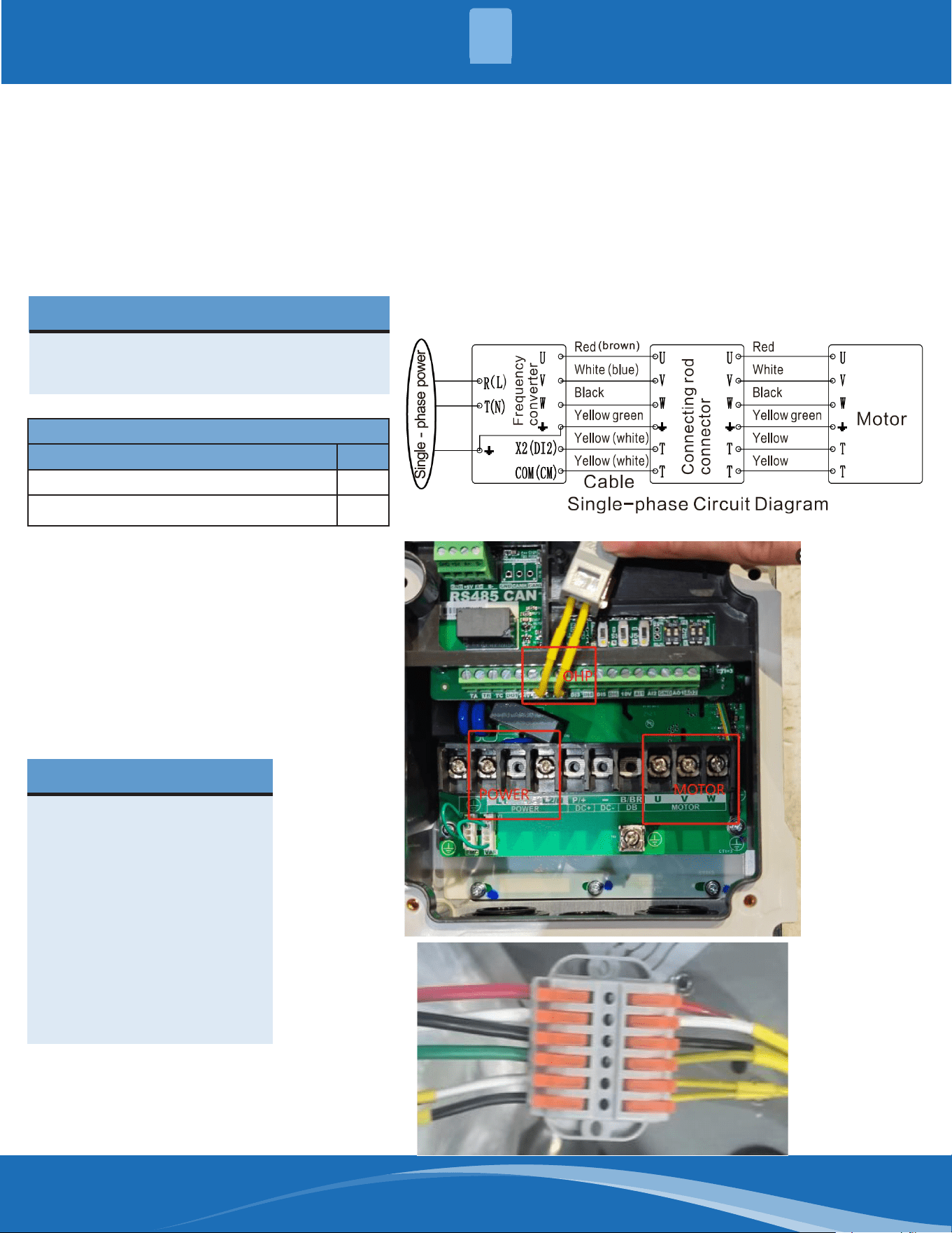
Select the location to install the controller. Connect the motor and the main power to the controller as required.
Check whether there are obstacles around the fan to aect its operation and operate the fan according to the
operation manual of the controller.
NOTE
The phase sequence of the motor
connected to the controller cannot be
incorrect.
Accessories Needed:
Name Qty.
Permanent Magnet Motor Controller 1
Rubber Sheathed Cable
2
NOTE
Do not connect the main
power directly to the ceiling
fan. Conrm whether the
power voltage matches the
controller voltage. After
connecting the power cord,
pull to verify the power cord
is reliable. When connecting
the fast terminal, the power
cord should be peeled
10mm and inserted into
the card slot at a depth of
17mm.
24-FT FAN INSTALLATION
4
mrcool.com17
CONTROL PANEL OPERATION
5
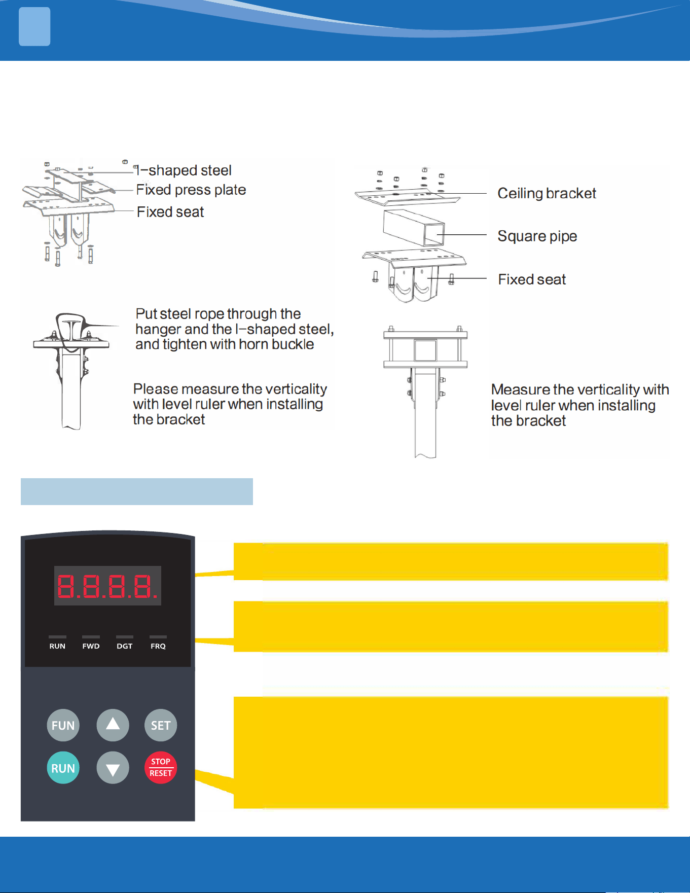
I-Shaped Steel Structure Installation
Diagram:
(The rest are the same as 16 ft. fan.) Expansion screw
hook is not available and the end of the steel rope can
be tied to the I-beam with the steel rope clamp.
Square-Steel Structure Installation
Diagram:
(The rest are the same as 16 ft. fan.) Expansion screw
hook is not available and the end of the steel rope can
be tied to the square steel beam with the steel rope
clamp.
5 - Control Panel Operation
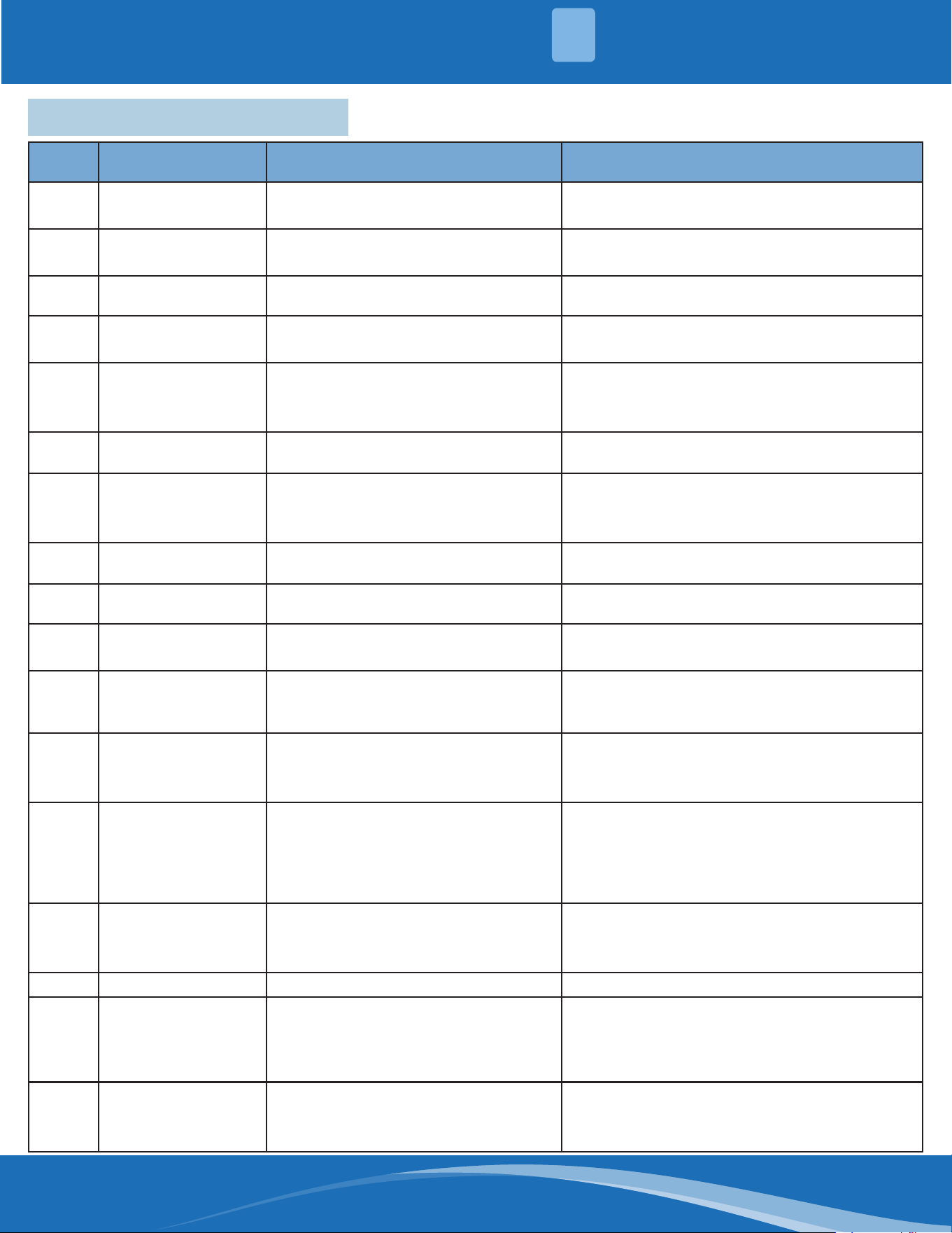
The panel covers three sections: data display section, status indicating section, and keypad operating section.
LED shows running frequency, ashing target frequency, function code,
parameter value, or fault code.
4 LEDs indicate working status. RUN is lit when running. FWD is lit when
working forward. FRQ is lit when showing.
Press "Fun" for function code, and "Set" for original parameters. Up and
down arrow keys can be used to select function codes and parameters.
Press "Set" again to conrm. In keypad control mode, the up and down
keys can also be used for dynamic speed control. "Run" and "Stop/Reset"
keys control start and stop. Press "Stop/Reset" key to reset inverter to fault
status.
mrcool.com 18
18
TROUBLESHOOTING
6
6 - Troubleshooting
Fault
Code
Description Causes Solutions
OC
Over-current
protection
-Short circuit at output side
-Motor is locked or overloaded
-Check whether the motor cable is damaged
-Check whether the motor is stuck
OE
DC over-voltage
protection
-Power voltage is too high
-Deceleration inertia is too large
-Check whether the rated voltage is input
-Increase deceleration time
PF1
Input phase loss
protection
-Phase loss of input power -Check whether the power input is normal
OL1
Converter overload
protection
Overload -Reduce load
-Increase the capacity of converter
OL2
Motor overload
protection
Overload -Reduce load
-Check mechanical devices
-Increase the capacity of converter
LU
Under-voltage
protection
Input voltage is too low Check whether the power voltage is normal
OH
Converter overheat
protection
-The n is too dirty
-The fan is damaged
-Ambient temperature is too high
-Clean the air inlet and n
-Replace the fan
-Increase ventilation
ESP
External fault External emergency stop terminal
functions
Check the external terminal fault signal
Err2
Parameter
measurement error
Motor is not connected during
parameter
Connect the motor correctly
Err3
Current fault before
operation
There is current alarm signal before
operation
-Check whether the cable is securely connected
-Contact the manufacturer
Err4
Current zero
deviation fault
-Cable is loose
-The current detection device is
damaged
-Check and connect the cable again
-Contact the manufacturer
PFO
Output phase loss -Motor is disconnected
-Motor is broken
-Frequency converter has fault
-Check the motor connecting wire carefully
-Replace the motor
-Contact the manufacturer
GP
Grounding
Protection
-Motor cable is damaged & short-
circuited to the ground
-The motor insulation is damaged &
short-circuited to the ground
-Frequency converter has fault
-Replace the cable
-Repair the motor
-Contact the manufacturer
PCE
PMSM
maladjustment fault
-Acceleration time is too short
-Overload
-Motor is locked
-Increase the acceleration time
-Check whether the motor is overloaded
ALM on Faulty Report fault Stop/Reset
OH1
Motor overheat
protection
-Ambient temperature is too high
-Open circuit of temperature control
circuit
-Motor temperature is too high
-Increase ventilation
-Repair the temperature control circuit
-Increase motor heat dissipation
Key
Failure
Instruction is invalid -Cable is loose
-Frequency converter has fault
-Plug the cable securely
-Turn o the power and power on again
-Contact the manufacturer

Industrial HVLS Fan
The design and specications of this product and/or manual are subject to change without prior notice.
Consult with the sales agency or manufacturer for details.