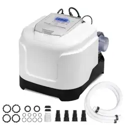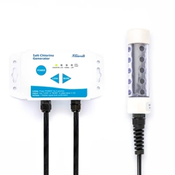
SKU: 90187 / 90188 / 90189
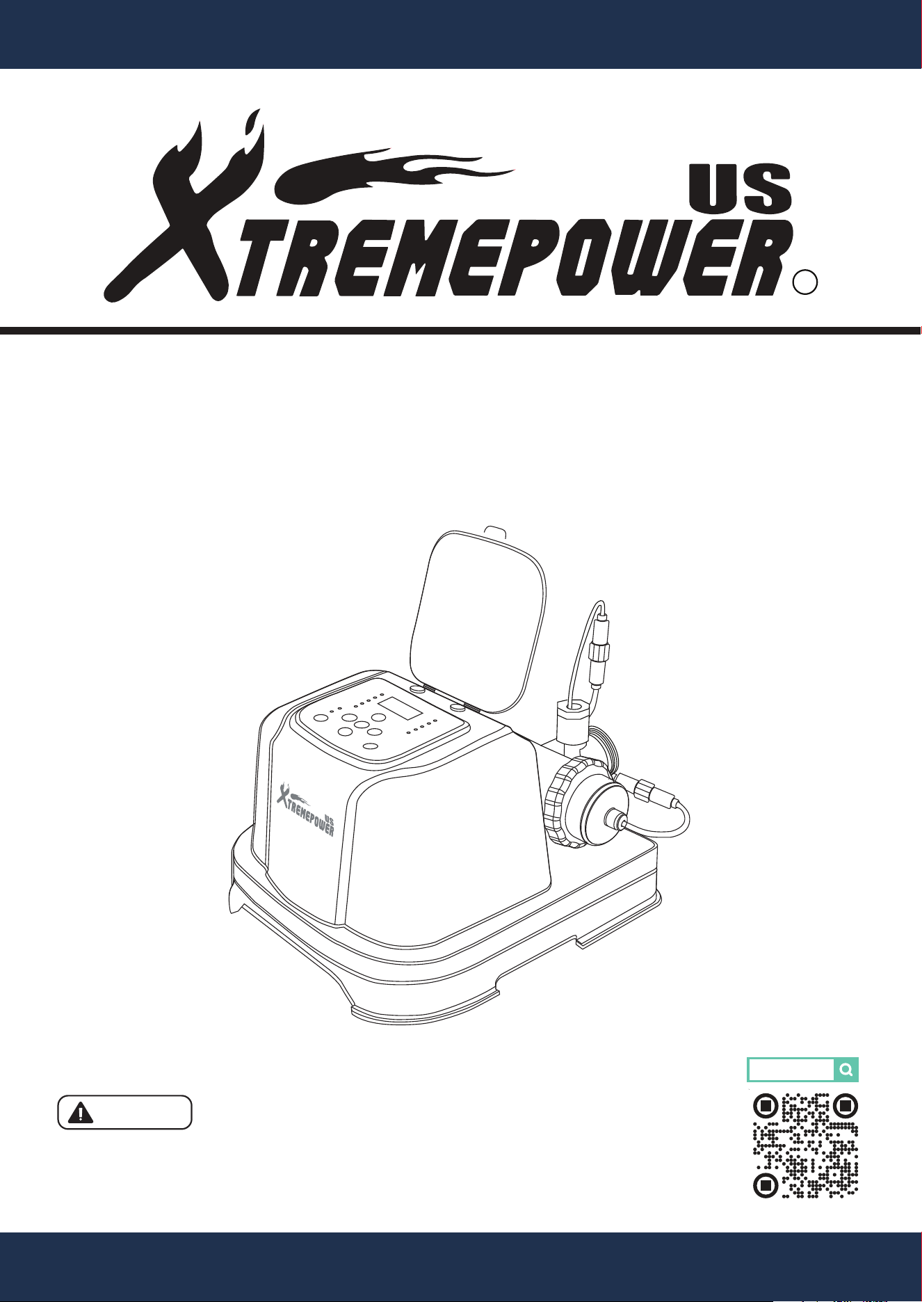
ABOVE-GROUND POOL SALT CHLORINATOR
5,000 / 10,000 / 20,000 GALLON
90187-89
Read all safety warnings and instructions. Failure to follow the warnings and
instructions may result in electric shock, fire and/or serious injury. Save all
warnings and instructions for future reference.
INSTALLATION AND USER’S GUIDE
DANGER
Low Salt
High Salt
Error
Boost
On / O
Pool Size
Flow
Add Salt
Salinity
Generating
sleep
Auto
AI Mode

TABLE OF CONTENTS
1
TABLE OF CONTENTS
IMPORTANT SAFETY INSTRUCTIONS
OVERVIEW (PRODUCT INFORMATION)
DIMENSIONS
INSTALLATION
INSTALLATION INSTRUCTIONS
OPERATION
CONTROL PANEL / FUNTIONS OF INDICATOR / FUNTIONS OF OPERATION
REPLACEMENT PARTS 23
Disclaimer
Legends and Symbols
DISCLAIMER 24
1
24
2
2-3
4
6
7
7-8
Customer Service and Technical Support 24
PRODUCT INTRODUCTION
5
9
TROUBLESHOOTING
22
10-21
TROUBLESHOOTING
22
PARTS DIAGRAM
23
PACKAGING CONTENTS
4
PARTS LIST
23
SPECIFICATION
6
CUSTOMER SERVICE
If you have any questions about ordering our pool pumps and replacement parts or pool products,
please feel free to contact us using the following contact information:
Customer Service and Technical Support
Phone: (909) 628-0880
Email: [email protected]
Hours of Operation: Monday – Friday, 9AM – 4PM (CST)
IMPORTANT SAFETY INSTRUCTIONS
2
For safety reasons, children should not be allowed to use this product. Packing
materials and plastic bags are not toys. Keep them away from children to prevent the risk of
suffocation.
Failure to comply with all instructions and warnings may lead to severe bodily
injury or even death. For optimal safety and functionality, it is advisable to have the product installed
and serviced by a certified service professional. Prior to using this product, installers, operators,
and owners must carefully review these warnings and all instructions provided in the owner's
manual. It is essential to leave these warnings and the owner's manual with the owner for their
reference and safety.
ATTENTION INSTALLER: This manual contains vital information regarding the installation,
operation, and safe use of this product. It is essential to provide this manual to the end user of the
product. Failure to read and follow all instructions could lead to severe injuries.
USE OF NON-XTREMEPOWERUS REPLACEMENT PARTS VOIDS WARRANTY
DANGER: Ignoring these hazards can result in death, severe personal injury, or
significant property damage.
WARNING: Indicates potential hazards that can result in severe personal injury,
death, or significant property damage. Ignoring these warnings presents a real
danger.
CAUTION: Indicates potential hazards that can result in minor or moderate
personal injury, property damage, or actions that are unpredictable and unsafe.
Ignoring these cautions presents a potential hazard.
NOTICE: This label indicates important special instructions that are not directly
related to hazards.
This guide provides instructions for installing and using the Above-Ground Pool Salt Chlorinator.
For inquiries about the equipment, please contact XtremepowerUS.
This guide contains important information about safely installing and operating this product. After
installation, make sure to share this information with the owner/operator or leave it with them for
their reference.
Legends and Symbols
When encountering the safety-alert symbol on the equipment or within this manual, pay attention to
the following signal words and remain vigilant about the potential for personal injury.
IMPORTANT SAFETY INSTRUCTIONS
DANGER
WARNING
WARNING
CAUTION
NOTE
DANGER
3
DANGER
WARNING
CAUTION
• Storable Pools Only: Use this product with storable pools, not permanently-installed pools. The
pool must be installed no closer than 6 feet (1.8 m) from any electrical outlet, with portable
appliances kept at least 5 feet (1.5 m) away to reduce the risk of electric shock.
• Proper Installation and Use: Incorrect installation or use could lead to reduced product efficiency
and safety hazards.
NOTE
• These guidelines address common risks and do not cover all potential dangers. Always exercise
caution and use good judgment when engaging in water activities. For use with portable
above-ground pools only.
• Outdoor Use Only: This product is designed exclusively for outdoor use.
• Supervision Required: Never allow children to use this product unsupervised. Children and
those with disabilities must be closely monitored to prevent injury.
• Assembly and Disassembly: These tasks should only be performed by adults to prevent acci-
dents.
• Electric Shock Prevention: Always disconnect the product from the electrical outlet before clean-
ing, servicing, or making adjustments. Do not replace the supply cord as this could lead to elec-
tric shock; if damaged, replace the appliance. Avoid using extension cords or adapters and
ensure a properly located outlet is used.
• Risk of Electric Shock: Do not bury the electrical cord or place it where it can be damaged.
Always use a grounded type receptacle equipped with a ground-fault circuit interrupter (GFCI).
Do not use the unit with a damaged cell housing or if improperly assembled. Ensure the GFCI
functions correctly by testing it; if it fails or if it trips without the test button being pressed, discon-
tinue use and seek professional repair. Failure to comply may result in severe injury or death.
IMPORTANT SAFETY INSTRUCTIONS
PRODUCT OVERVIEW
4
OVERVIEW (PRODUCT INFORMATION)
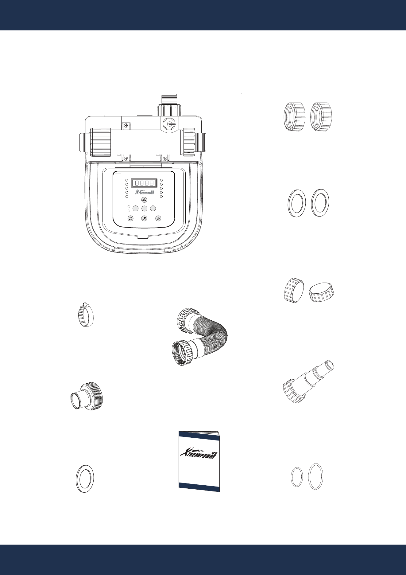
PACKAGING CONTENTS
PARTS#: 5
GASKET
1 PC(S)
PARTS#:
4
38 TO 32 INTERFACE
1 PC(S)
SALTWATER SYSTEM
1 PC(S)
INSTRUCTION
MANUAL
1 PC(S)
PARTS#: 11
32/38 HOSE
FITTING
2 PC(S)
PARTS#: 12 &13
O-RING
2 PC(S)
PARTS#: 10
HOSE NUT
2 PC(S)
PARTS#: 8
WATER SEALING
GASKET
2 PC(S)
BOOST
ERROR
POOL SIZE
ADD SALT
FLOW
ON / OFF
HIGH SALT
LOW SALT
SALINITY
GENERATING
SLEEP
-
+
MENU
AUTO
AI MODE
PARTS#: 3
HOOP
1 PC(S)
PARTS#: 7
SHORT HOSE
CONNECTOR
1 PC(S)
PARTS#: 9
T1 SEALING
NUT
3 PC(S)
5
PRODUCT INFORMATION
PRODUCT OVERVIEW
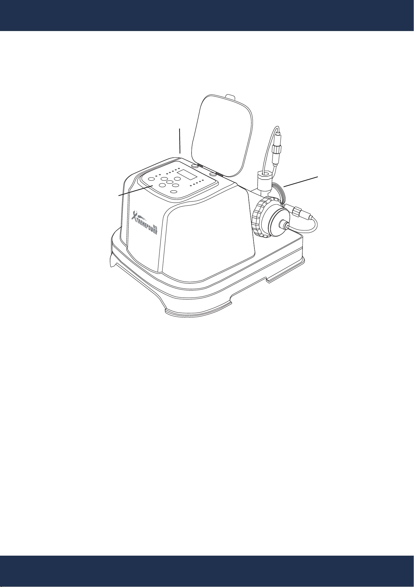
ELECTRONIC
CONTROL PANEL
INLET
OUTLET
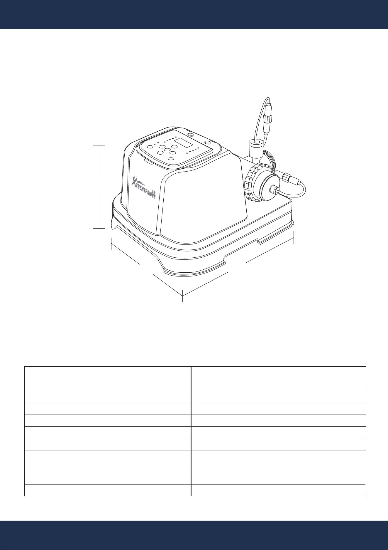
The XtremePower US About Ground Pool Salt Chlorinators are advanced water treatment systems
that utilize dissolved salt to generate chlorine for swimming pool sanitation. Through the process of
electrolysis, the system converts salt into chlorine gas and its active forms—hypochlorous acid and
sodium hypochlorite—which are widely used and highly effective disinfectants for pool water.
Designed for residential swimming pools, these systems provide a reliable and efficient method of
maintaining clean, clear, and hygienic water while reducing the need for manual chemical handling.
The About Ground Pool Salt Chlorinators feature an advanced automatic adjustment system, which
intelligently regulates chlorine production based on pool size and environmental conditions. This
ensures optimal water quality while improving energy efficiency and reducing maintenance effort.
INTRODUCTION
SALTWATER SYSTEM
Low Salt
High Salt
Error
Boost
On / O
Pool Size
Flow
Add Salt
Salinity
Generating
sleep
Auto
AI Mode
6
PRODUCT OVERVIEW
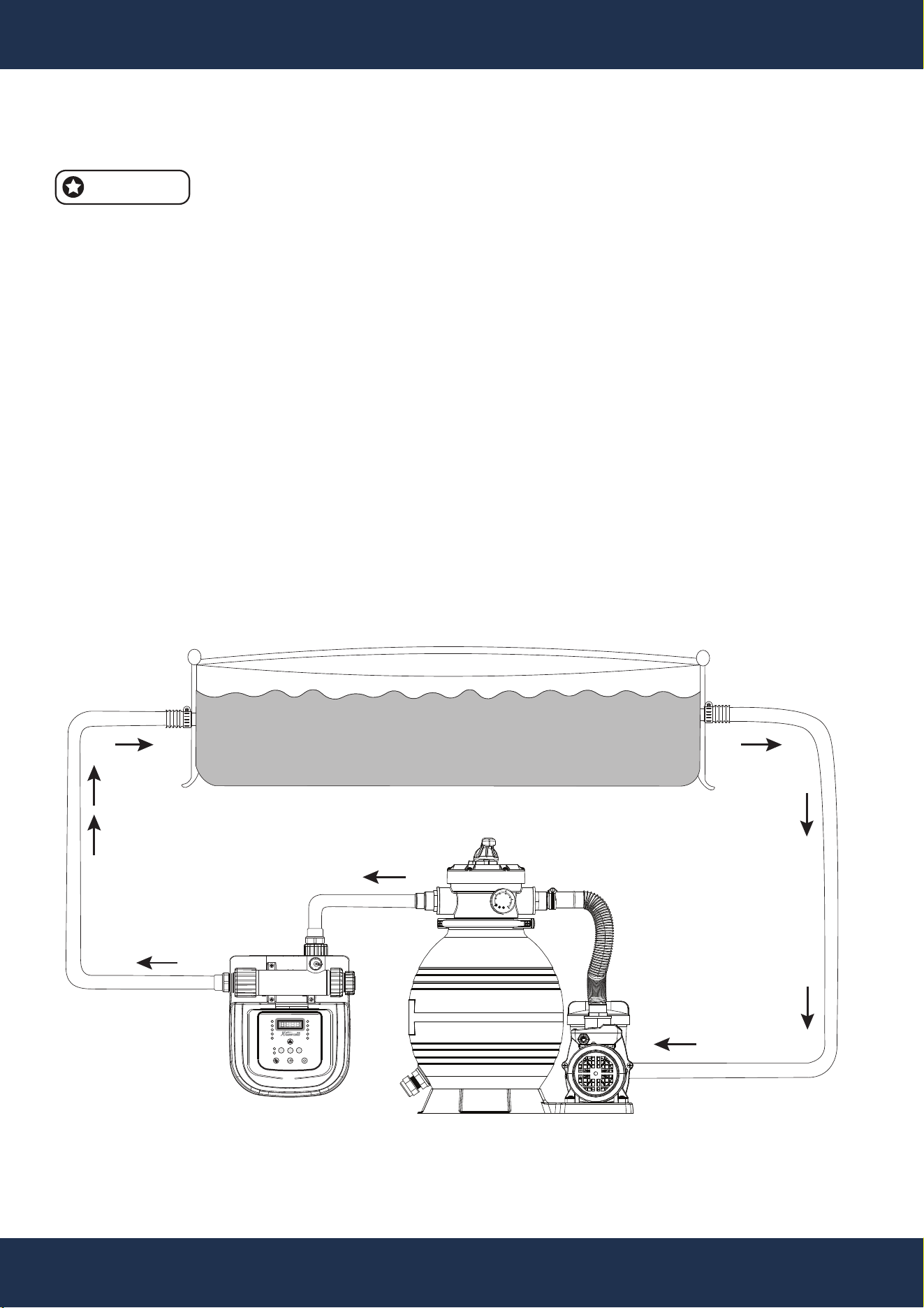
SPECIFICATION
DIMENSIONS
SKU
POOL TYPE
POOL CAPACITY
PRODUCT DIMENSION
PRODUCT WEIGHT
VOLTAGE
FREQUENCY
MAXIMUM POWER
IDEAL SALT LEVEL
CELL OUTPUT / HOUR
FILTER PUMP MINIMUM FLOW RATE
90187 / 90188 / 90189
ABOVE-GROUND POOLS
UP TO 5,000 / 10,000 / 20,000 GALLONS
15.72 x 14.17 x 10.43 INCH(s)
10 LB(s)
120V
60 Hz
115 W
3000 - 4000 PPM
5 / 10 / 20 GRAMS PER HOUR
3300 GPH (GALLON PER HOUR)
14.17 IN
15.72 IN
10.43 IN
Low Salt
High Salt
Error
Boost
On / O
Pool Size
Flow
Add Salt
Salinity
Generating
sleep
Auto
AI Mode
7
INSTALLATION
INSTALLATION INSTRUCTIONS
INSTALLATION
NOTE
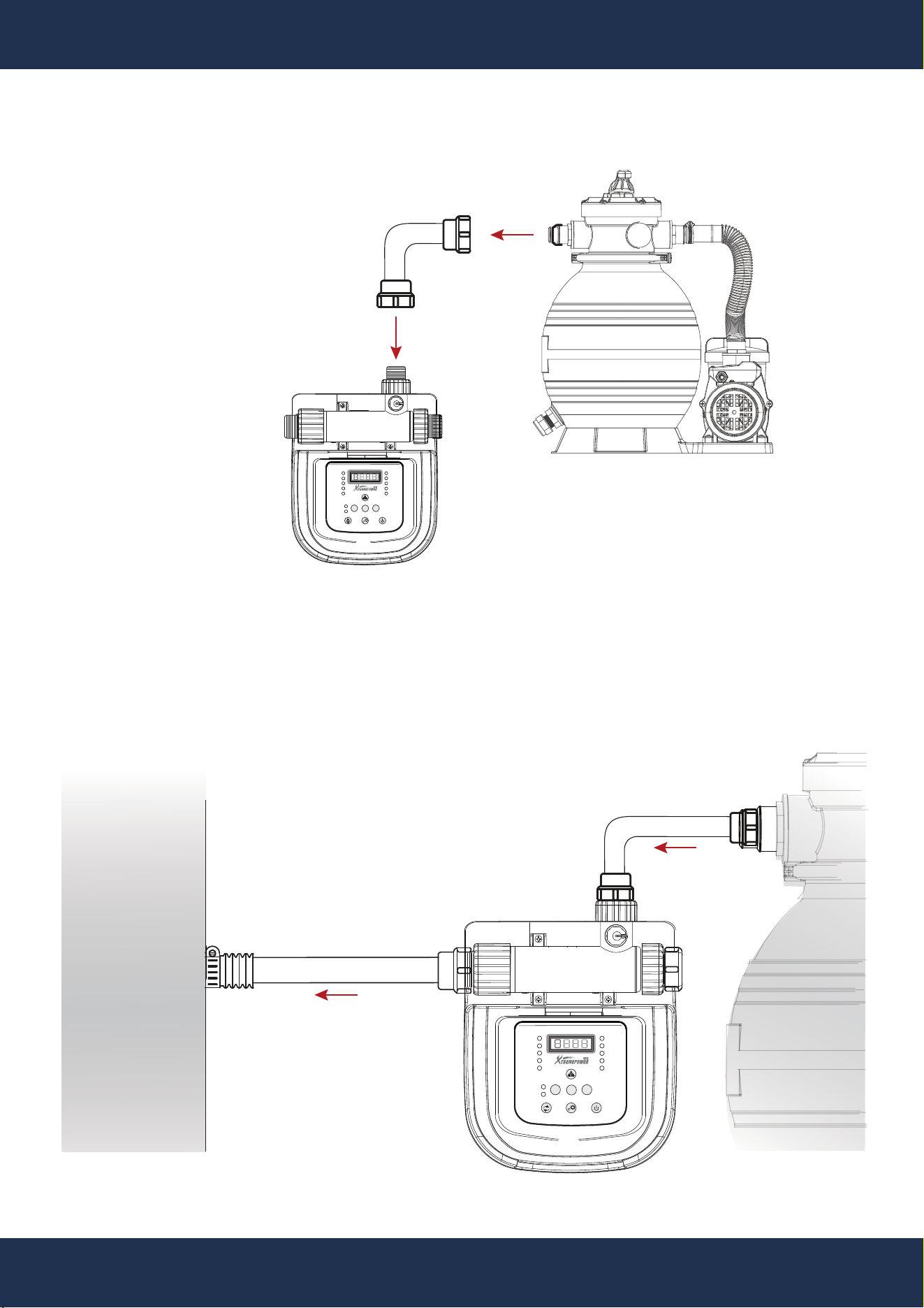
• Install the Saltwater System as the final component in the water return line to the pool to protect
the titanium plates.
• Ensure a separate filter pump with a flow rate between 700 to 3300 GPH (2650 to 11,355 LPH)
for effective operation.
• Pool Preparation: Assemble a new pool and filter pump, or shut off the existing setup.
• Positioning: Position the Saltwater System downstream of the pump and filter (see Figure A).
• Connections: Connect the system inlet to the pump outlet using appropriate hoses and
adapters, depending on the pump and pool connections (see Figure B).
• Secure Connections: Tighten all connections securely to prevent leaks.
• Testing: Test the system to ensure proper function before regular use.
POOL PUMP AND SAND FILTER
(NOT INCLUDED)
BOOST
ERROR
POOL SIZE
ADD SALT
FLOW
ON / OFF
HIGH SALT
LOW SALT
SALINITY
GENERATING
SLEEP
-
+
MENU
AUTO
AI MODE
Figure A Above-Ground Swimming Pool Equipment Layout
ABOVE-GROUND POOL WITH SALTWATER
POOL CLEAR
SALTWATER
SYSTEM
POOL
INLET PORT
POOL
OUTLET PORT
psi
bar
KL1.6
1
0
10
20
30
50
60
2
3
4
40
POOL PUMP AND SAND FILTER
(NOT INCLUDED)
POOL CLEAR
SALTWATER
SYSTEM
8
INSTALLATION
PARTS#: 8
Figure B Water Intake Hose Connection
PUMP OUTLET PORT
SALTWATER SYSTEM
INLET PORT
BOOST
ERROR
POOL SIZE
ADD SALT
FLOW
ON / OFF
HIGH SALT
LOW SALT
SALINITY
GENERATING
SLEEP
-
+
MENU
AUTO
AI MODE
Figure C Water Hose Connection Completed
POOL CLEAR
SALTWATER
SYSTEM
ABOVE
GROUND
POOL
POOL
PUMP
BOOST
ERROR
POOL SIZE
ADD SALT
FLOW
ON / OFF
HIGH SALT
LOW SALT
SALINITY
GENERATING
SLEEP
-
+
MENU
AUTO
AI MODE
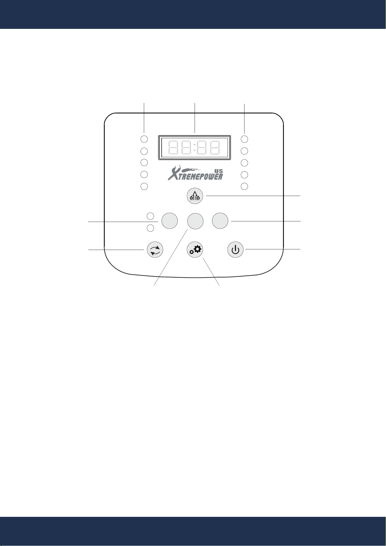
Pool Size: Pool size indicator. When the blue light is on, the digital display indicates the current
swimming pool size.
Flow: Flow switch indicator. The red light remains on to indicate that no water is flowing through
the system. The display panel shows “-FL-” and flashes to indicate that water flow is present but
not yet stable.
Add Salt: Add salt indicator. When the yellow light is on, the digital display indicates the amount of
salt that should be added.
Salinity: Salinity indicator. When the blue light is on, the digital display indicates the current salinity
level.
Generating / Sleep: Operation indicator. The red light indicates that chlorine production has
stopped, whereas the green light indicates that chlorine is being produced.
9
CONTROL PANEL
Interface Overview
OPERATION
DISPLAY
SETTINGS KEY
TRANSFER KEY POWER KEY
PLUS KEY
MINUS KEY
OPERATIONAL INDICATORS
▪ RED: SHUTDOWN
▪ BLUE: IN OPERATION
▪ GREEN: STANDBY MODE
MENU KEY
BOOST KEY
INDICATORS LIGHT
INDICATORS LIGHT
BOOST
ERROR
POOL SIZE
ADD SALT
FLOW
ON / OFF
HIGH SALT
LOW SALT
SALINITY
GENERATING
SLEEP
-
+
MENU
AUTO
AI MODE
FUNTIONS OF THE INDICATORS
OPERATION
10
OPERATION
Auto: Auto mode indicator. The green light is on when the system is set to auto mode.
AI Mode: AI mode indicator. The green light is on when the system is set to AI mode.
Boost: Boost mode indicator. The blue light is on when the system is set to boost mode.
Low Salt: Low salt indicator. The red light remains on, indicating that the salinity is below
the minimum threshold. In this condition, the electrode stops producing chlorine and salt must be
added. A flashing red light indicates low salinity and that salt should be added.
High Salt: High salt indicator. The red light remains on, indicating that the salinity exceeds the
maximum threshold. In this condition, the electrode stops producing chlorine and water must be
added. A flashing red light indicates excessively high salinity and that water should be added.
Error: Error indicator. The red light indicates that an error has occurred, and the electrode has
stopped producing chlorine.
On/Off: Power indicator. The green light indicates that the salt chlorinator is on.
FUNTIONS OF THE INDICATORS
FUNTION OF THE KEY
Power Key: Press this key to turn the power on or off.
Setting Key: Press this key to set the pool size or to activate the child lock function.
Transfer Key: Press this key to switch between auto mode and manual mode.
Plus Key (+): Press this key to increase values or to change the temperature unit.
Minus Key (–): Press this key to decrease values or to change the temperature unit.
Menu Key: Press this key to switch the display interface.
Boost Key: Press this key to activate boost mode.
+
-
MENU
11
OPERATION
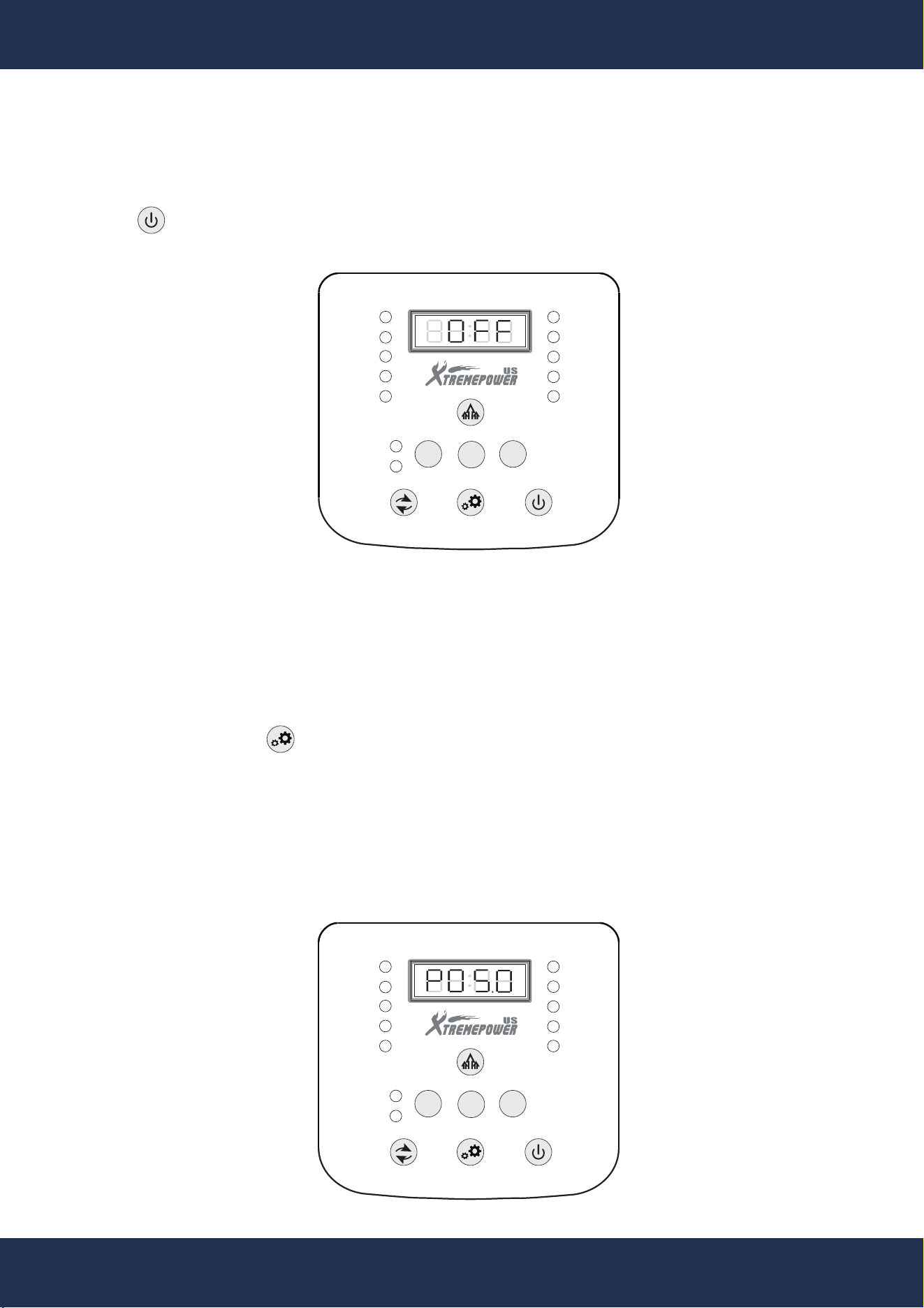
1. SYSTEM START/STOP
Press the Power key to turn the system on or off. The ON/OFF indicator illuminates or turns off
accordingly, indicating the system status. When the device is turned off, the display panel shows
“OFF.”
FUNTIONS OPERATION
BOOST
ERROR
POOL SIZE
ADD SALT
FLOW
ON / OFF
HIGH SALT
LOW SALT
SALINITY
GENERATING
SLEEP
-
+
MENU
AUTO
AI MODE
2. POOL SIZE SETTING
a) Initial Setting
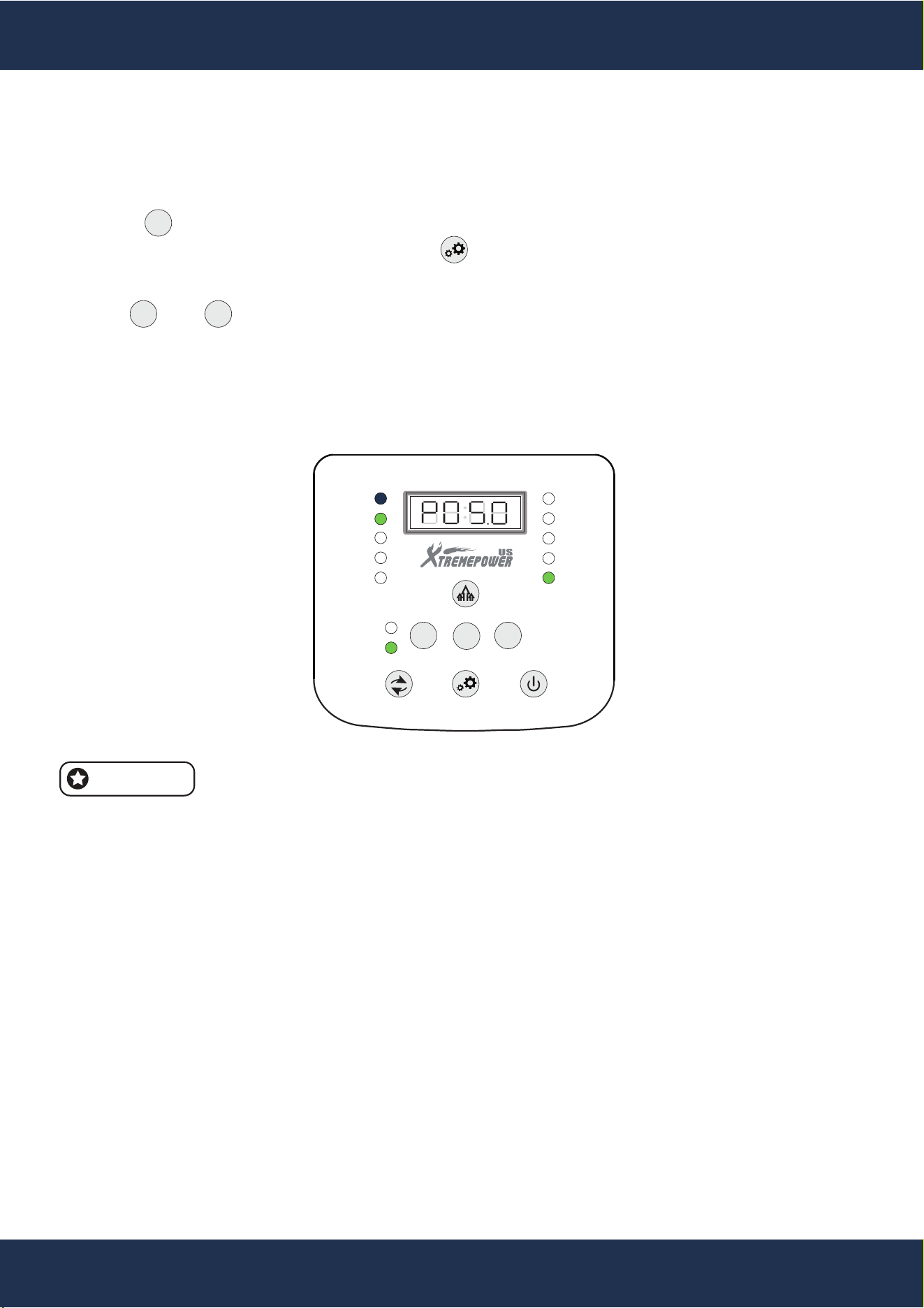
When the device is powered on for the first time, it performs a self-check. After completion, the
display panel shows “PXX.X” and flashes, indicating that the pool size can be set.
Use the “+” and “–” keys to adjust the pool size. The adjustment increment is 100 gallons, and the
unit is gallons. Press the Setting key to save the selection.
If no setting is made within 30 seconds, the system automatically applies a default pool size and
enters the water flow detection interface.
Default Pool Size Values:
▪ 90187: 5,000 GALLONS
▪ 90188: 10,000 GALLONS
▪ 90189: 20,000 GALLONS
BOOST
ERROR
POOL SIZE
ADD SALT
FLOW
ON / OFF
HIGH SALT
LOW SALT
SALINITY
GENERATING
SLEEP
-
+
MENU
AUTO
AI MODE
12
OPERATION
FUNTIONS OPERATION
b) Normal Setting
Press the Setting key to access the pool size setting interface.
The display panel shows “PXX.X.” Press the Setting key again; the value will flash, indicating
that it can be adjusted.
Use the and keys to adjust the value. Press the Setting key to save and exit.
In AI mode, the system automatically adjusts chlorine production time based on parameters such as
temperature and pool size to ensure adequate chlorine levels and extend electrode life.
In Auto mode, the operating time remains unchanged after the pool size is set.
The adjustable range depends on the salt cell model. Values outside the allowable
range cannot be selected.
Pool Size Ranges:
▪ 90187: 5,000 GALLONS
▪ 90188: 10,000 GALLONS
▪ 90189: 20,000 GALLONS
When this interface is active, the Pool Size indicator remains solid blue.
3. WATER FLOW DETECTION
a) Initial Detection
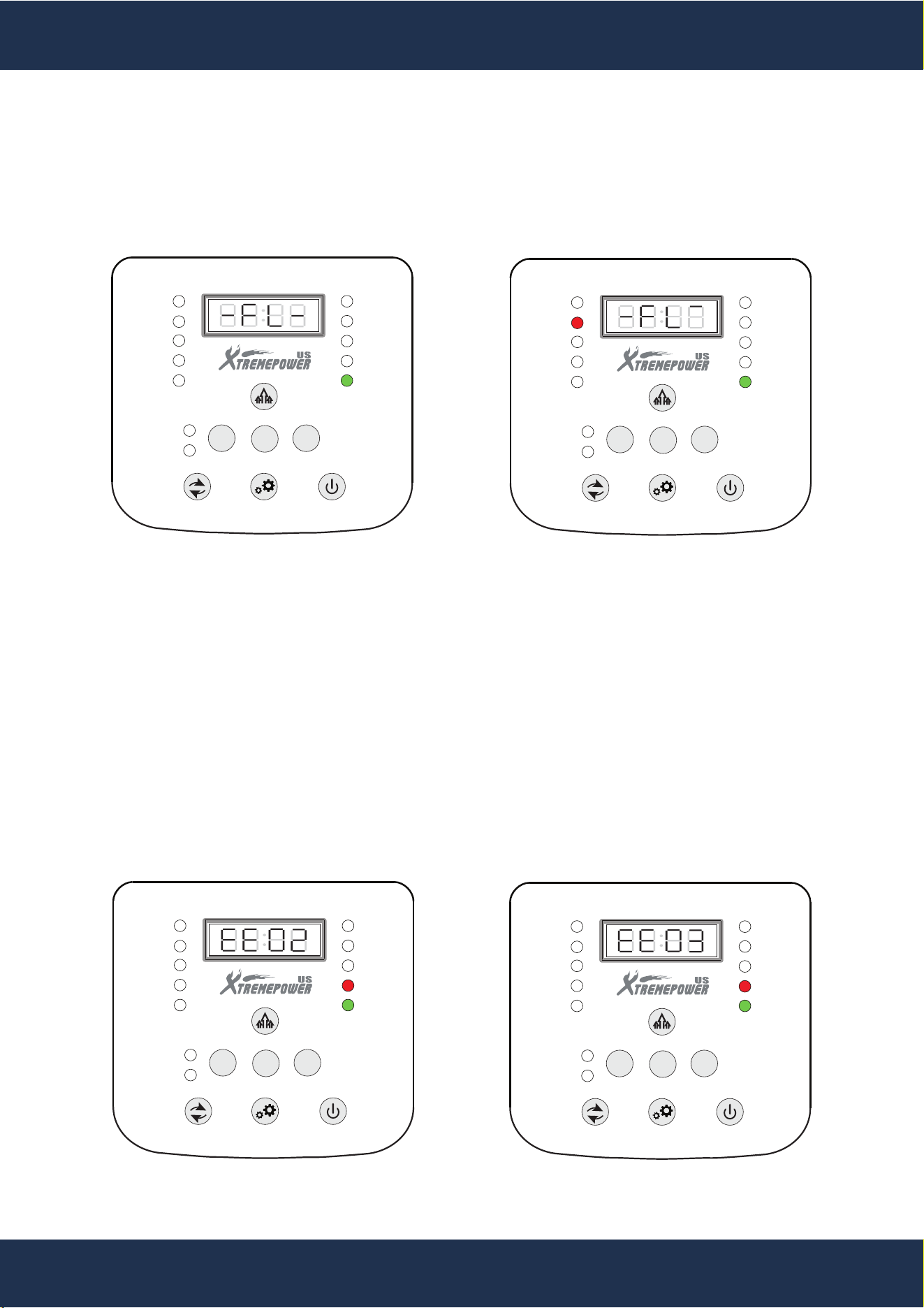
When water flow is detected, the display panel shows “-FL-” and flashes. After one minute of
continuous detection, the system begins operation, and the flow indicator turns solid green.If water
flow is interrupted, detection restarts, and the indicator turns red. During detection, all keys except
the Power key are locked.
BOOST
ERROR
POOL SIZE
ADD SALT
FLOW
ON / OFF
HIGH SALT
LOW SALT
SALINITY
GENERATING
SLEEP
-
+
MENU
AUTO
AI MODE
NOTE
+
-
MENU
13
OPERATION
FUNTIONS OPERATION
BOOST
ERROR
POOL SIZE
ADD SALT
FLOW
ON / OFF
HIGH SALT
LOW SALT
SALINITY
GENERATING
SLEEP
-
+
MENU
AUTO
AI MODE
BOOST
ERROR
POOL SIZE
ADD SALT
FLOW
ON / OFF
HIGH SALT
LOW SALT
SALINITY
GENERATING
SLEEP
-
+
MENU
AUTO
AI MODE
b) Detection During Operation
If the system is operating and no water flow is detected, the display panel continues to show “-FL-,”
and the flow indicator remains red.
4. WATER TEMPERATURE DETECTION
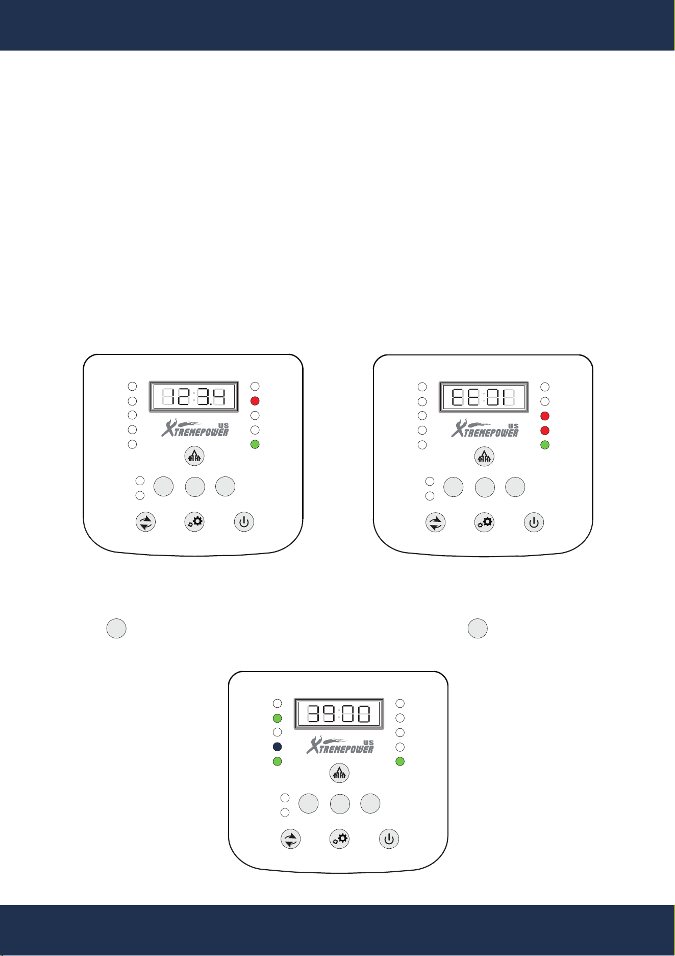
After water flow detection, the system initiates temperature monitoring. The operating temperature
range is 50°F to 140°F.
If the temperature falls outside this range, the system activates a protection program and stops
operation.
▪ “EE02”: Temperature above 140°F (error indicator turns red)
▪ “EE03”: Temperature below 50°F (error indicator turns red)
The system resumes normal operation once the temperature returns to the acceptable range.
In a high-temperature condition, operation resumes when the temperature drops below 131°F.
In a low-temperature condition, operation resumes when the temperature rises above 55.4°F.
BOOST
ERROR
POOL SIZE
ADD SALT
FLOW
ON / OFF
HIGH SALT
LOW SALT
SALINITY
GENERATING
SLEEP
-
+
MENU
AUTO
AI MODE
BOOST
ERROR
POOL SIZE
ADD SALT
FLOW
ON / OFF
HIGH SALT
LOW SALT
SALINITY
GENERATING
SLEEP
-
+
MENU
AUTO
AI MODE
HIGH TEMP LOW TEMP
14
OPERATION
FUNTIONS OPERATION
5. SALT SALINITH DETECTION
a) Salinity Range and Alerts
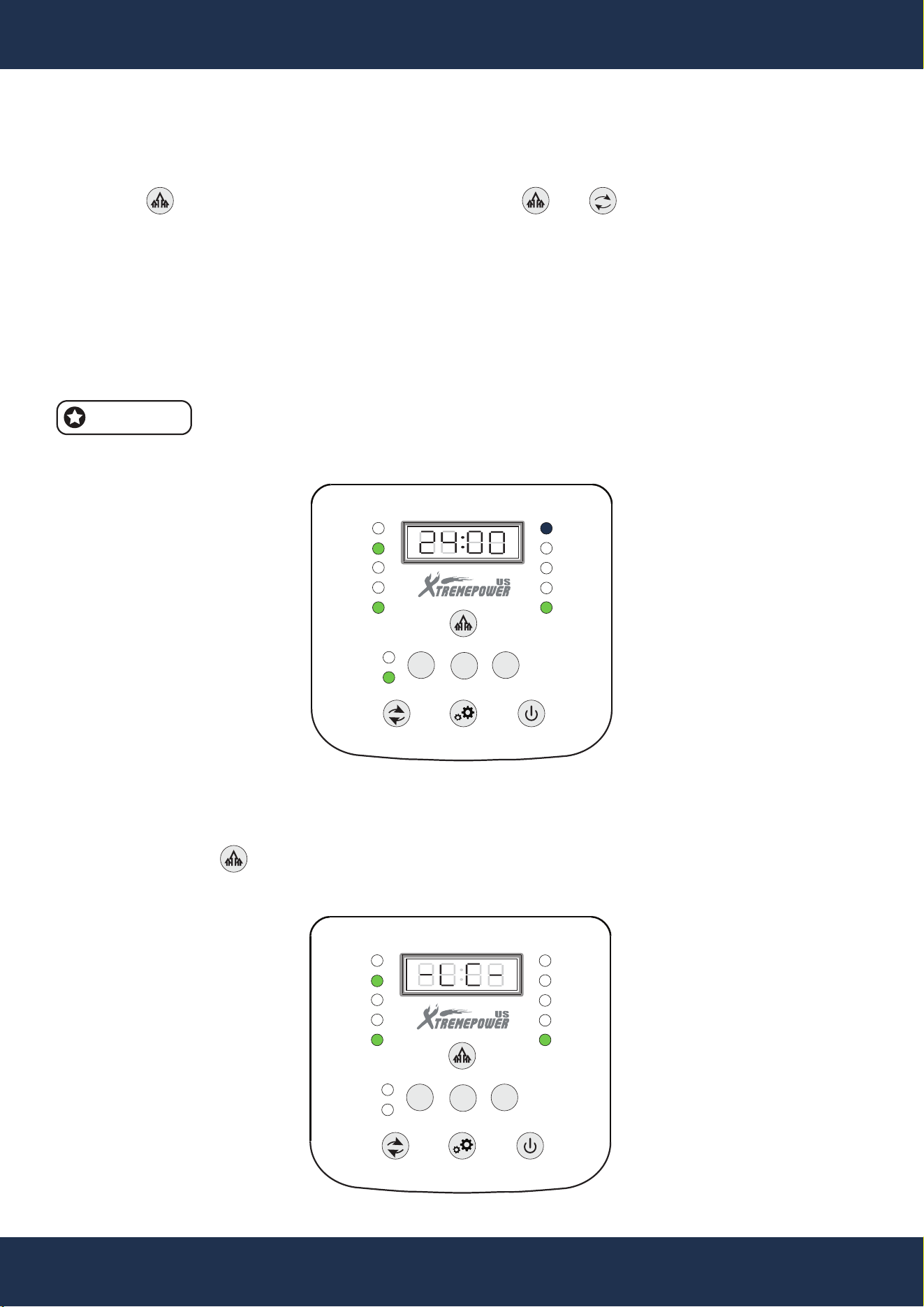
The operating salinity range is 2300–5500 ppm, with an ideal range of 3400–3600 ppm.
▪ 2300–2800 ppm: Warning state; Low Salt indicator flashes red
▪ Below 2300 ppm: Low Salt and Add Salt indicators turn on; the display shows the required salt
amount (unit: lb). The system stops operation.
▪ 4500–5500 ppm: Warning state; High Salt indicator flashes red
▪ Above 5500 ppm: High Salt and Error indicators turn on; the display shows error code “EE01.”
The system stops operation
The system resumes operation once salinity returns to the normal range.
BOOST
ERROR
POOL SIZE
ADD SALT
FLOW
ON / OFF
HIGH SALT
LOW SALT
SALINITY
GENERATING
SLEEP
-
+
MENU
AUTO
AI MODE
BOOST
ERROR
POOL SIZE
ADD SALT
FLOW
ON / OFF
HIGH SALT
LOW SALT
SALINITY
GENERATING
SLEEP
-
+
MENU
AUTO
AI MODE
LOW SALT SALINITY HIGH SALT SALINITY
b) Viewing Salinity
Press the shortcut key to display the current salinity (ppm). Press again to navigate to the
next screen, or allow the display to exit automatically after 6 seconds.
MENU MENU
BOOST
ERROR
POOL SIZE
ADD SALT
FLOW
ON / OFF
HIGH SALT
LOW SALT
SALINITY
GENERATING
SLEEP
-
+
MENU
AUTO
AI MODE
15
OPERATION
6. Boost Mode
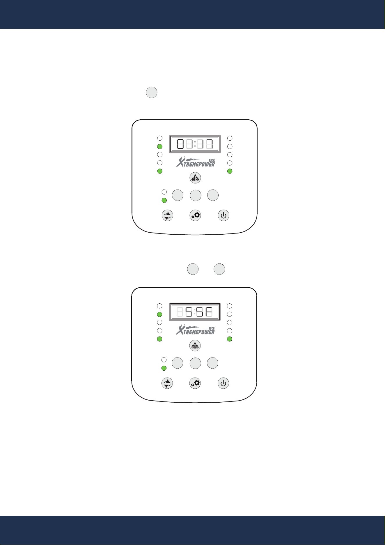
Press the Boost key to activate Boost mode. Press or to exit Boost mode.
When Boost mode is active:
▪ The Boost indicator turns blue
▪ Chlorine production runs continuously for 24 hours
After 24 hours, the system enters a 30-minute rest period (Generating/Sleep indicator turns red),
then returns to the previously selected mode (Auto or AI).
Boost mode is recommended during initial use, after extended inactivity, or when
chlorine production is insufficient.
FUNTIONS OPERATION
7. Child Lock Function
Press and hold the Boost key for more than 3 seconds to enable or disable the child lock.
NOTE
BOOST
ERROR
POOL SIZE
ADD SALT
FLOW
ON / OFF
HIGH SALT
LOW SALT
SALINITY
GENERATING
SLEEP
-
+
MENU
AUTO
AI MODE
BOOST
ERROR
POOL SIZE
ADD SALT
FLOW
ON / OFF
HIGH SALT
LOW SALT
SALINITY
GENERATING
SLEEP
-
+
MENU
AUTO
AI MODE
BOOST MODE
16
OPERATION
8. MENU INTERFACE
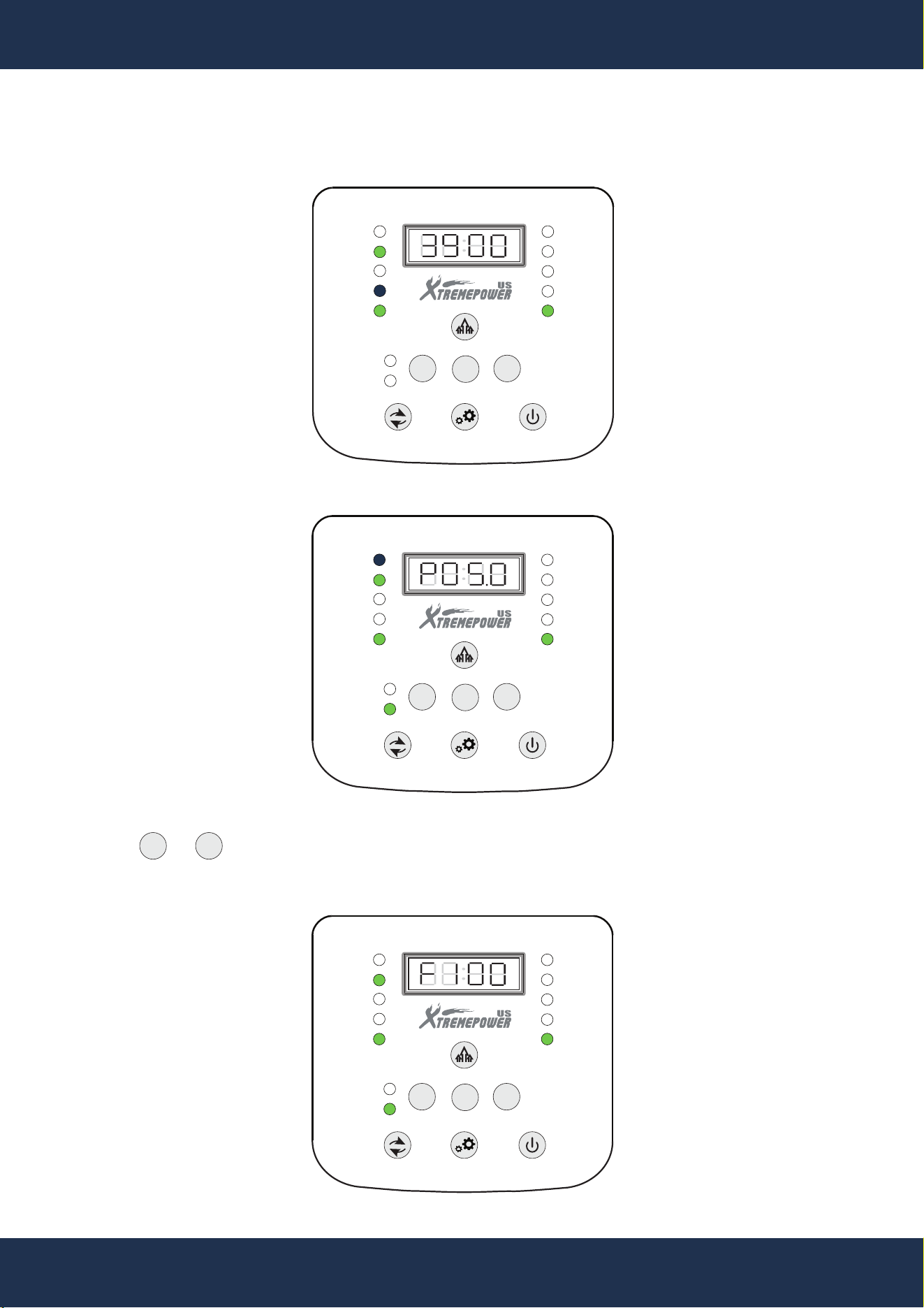
From the default display, press the Menu key to cycle through the following screens:
▪ Chlorine production/rest countdown
FUNTIONS OPERATION
+
-
MENU
▪ Water temperature (°F) — adjustable using or key.
BOOST
ERROR
POOL SIZE
ADD SALT
FLOW
ON / OFF
HIGH SALT
LOW SALT
SALINITY
GENERATING
SLEEP
-
+
MENU
AUTO
AI MODE
BOOST
ERROR
POOL SIZE
ADD SALT
FLOW
ON / OFF
HIGH SALT
LOW SALT
SALINITY
GENERATING
SLEEP
-
+
MENU
AUTO
AI MODE
17
OPERATION
FUNTIONS OPERATION
▪ Instant salinity
BOOST
ERROR
POOL SIZE
ADD SALT
FLOW
ON / OFF
HIGH SALT
LOW SALT
SALINITY
GENERATING
SLEEP
-
+
MENU
AUTO
AI MODE
▪ Pool size
BOOST
ERROR
POOL SIZE
ADD SALT
FLOW
ON / OFF
HIGH SALT
LOW SALT
SALINITY
GENERATING
SLEEP
-
+
MENU
AUTO
AI MODE
BOOST
ERROR
POOL SIZE
ADD SALT
FLOW
ON / OFF
HIGH SALT
LOW SALT
SALINITY
GENERATING
SLEEP
-
+
MENU
AUTO
AI MODE
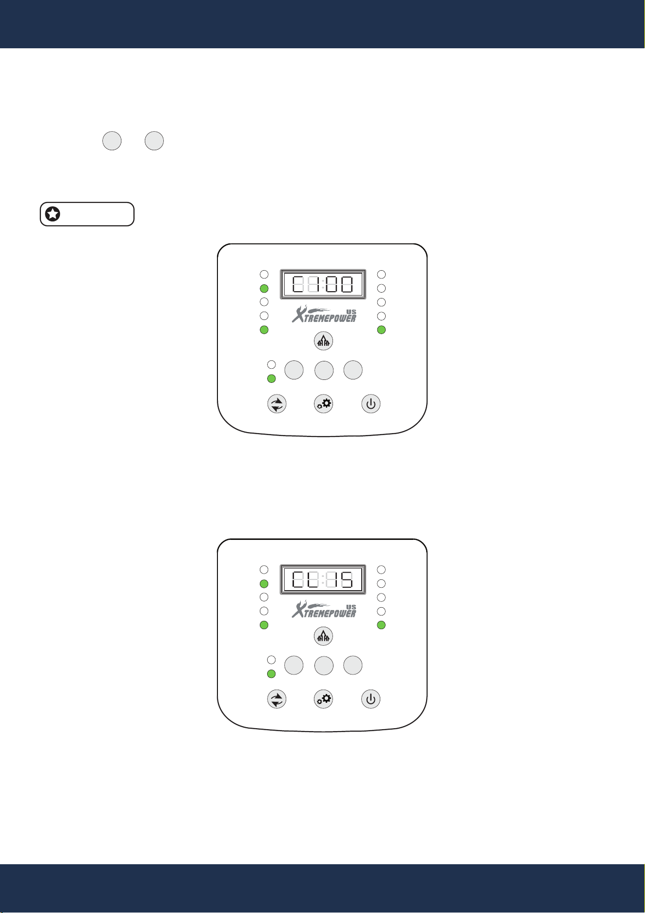
▪ Salt calibration coefficient - default: F100; adjustable from F75 to F120.
Press the or key to adjust the valve, the salt salinity will be adjusted with the value F75 to
F120.
For example: F120 represents salt concentration = 120%* basic salt salinity.
+
-
18
OPERATION
FUNTIONS OPERATION
BOOST
ERROR
POOL SIZE
ADD SALT
FLOW
ON / OFF
HIGH SALT
LOW SALT
SALINITY
GENERATING
SLEEP
-
+
MENU
AUTO
AI MODE
BOOST
ERROR
POOL SIZE
ADD SALT
FLOW
ON / OFF
HIGH SALT
LOW SALT
SALINITY
GENERATING
SLEEP
-
+
MENU
AUTO
AI MODE
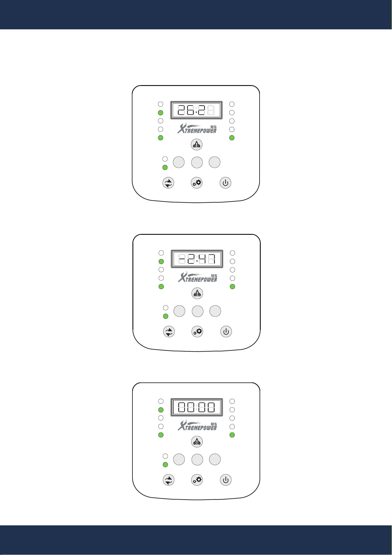
▪ Chlorine output adjustment - default: C100
Press the or key to adjust the valve, the salt salinity will be adjusted with the value C80 to
C120.
For example: C120 represents salt concentration = 120%* basic chlorine production time.
This function is only available in AI mode.
▪ Salt cell model (automatically detected: CL05, CL10, CL15, CL20)
The machine will automatically identify the electrode model. There is no need to manually set the
electrode, as it can be used immediately.
+
-
NOTE
19
OPERATION
FUNTIONS OPERATION
BOOST
ERROR
POOL SIZE
ADD SALT
FLOW
ON / OFF
HIGH SALT
LOW SALT
SALINITY
GENERATING
SLEEP
-
+
MENU
AUTO
AI MODE
BOOST
ERROR
POOL SIZE
ADD SALT
FLOW
ON / OFF
HIGH SALT
LOW SALT
SALINITY
GENERATING
SLEEP
-
+
MENU
AUTO
AI MODE
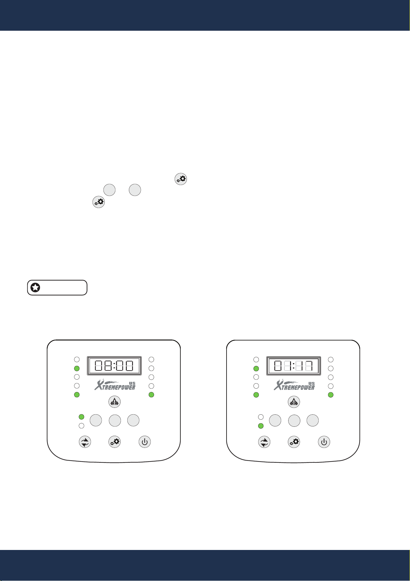
▪ Salt cell voltage (V)
▪ Current of the Salt Cell (A)
▪ Total Chlorine Production Time
BOOST
ERROR
POOL SIZE
ADD SALT
FLOW
ON / OFF
HIGH SALT
LOW SALT
SALINITY
GENERATING
SLEEP
-
+
MENU
AUTO
AI MODE
20
OPERATION
FUNTIONS OPERATION
9. AUTO AND AI MODE
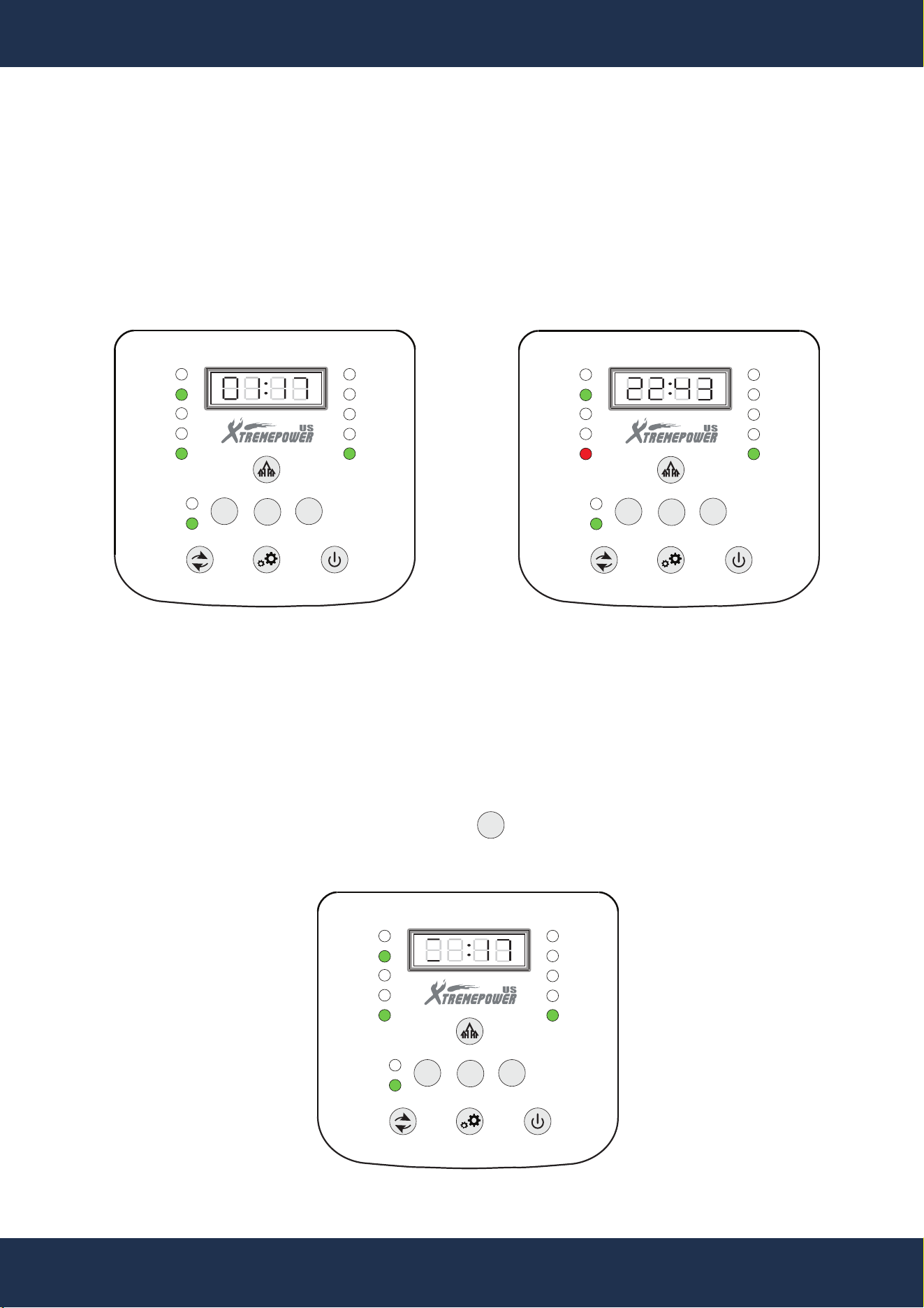
AUTO MODE
In Auto mode, the chlorine production time is manually set and stored in memory.
For example: If set to 8 hours, the system operates for 8 hours and rests for 16 hours. This cycle
repeats, even after a power interruption.
Adjustment Procedure:
▪ Switch to Auto mode
▪ In the default interface, press the Setting key (time display flashes)
▪ Adjust using or (range: 00:30–12:00)
▪ Press the Setting key to confirm
The chlorine production time remains fixed unless manually changed.
AI MODE
Switch to AI mode and set the correct pool size. The system automatically calculates and adjusts
chlorine production time based on environmental conditions and salinity.
Production time may vary due to temperature and weather. Reduced production
at low temperatures is normal.
+
-
NOTE
BOOST
ERROR
POOL SIZE
ADD SALT
FLOW
ON / OFF
HIGH SALT
LOW SALT
SALINITY
GENERATING
SLEEP
-
+
MENU
AUTO
AI MODE
BOOST
ERROR
POOL SIZE
ADD SALT
FLOW
ON / OFF
HIGH SALT
LOW SALT
SALINITY
GENERATING
SLEEP
-
+
MENU
AUTO
AI MODE
AUTO MODE AI MODE
21
OPERATION
FUNTIONS OPERATION
10. OPERATING STATUS
Green indicator: Chlorine is being generated; the display shows remaining working time
Red indicator: System is resting; the display shows remaining rest time
The countdown screen is the default interface and operates on a 24-hour cycle.
+
11. SALT CELL SELF-CLEANING
The salt cell automatically reverses polarity every 8 hours for self-cleaning.
To manually reverse polarity, press and hold the key. Successful reversal can be verified by
observing a change in current direction.
BOOST
ERROR
POOL SIZE
ADD SALT
FLOW
ON / OFF
HIGH SALT
LOW SALT
SALINITY
GENERATING
SLEEP
-
+
MENU
AUTO
AI MODE
BOOST
ERROR
POOL SIZE
ADD SALT
FLOW
ON / OFF
HIGH SALT
LOW SALT
SALINITY
GENERATING
SLEEP
-
+
MENU
AUTO
AI MODE
WORKING STATUS RESTING STATUS
BOOST
ERROR
POOL SIZE
ADD SALT
FLOW
ON / OFF
HIGH SALT
LOW SALT
SALINITY
GENERATING
SLEEP
-
+
MENU
AUTO
AI MODE
22
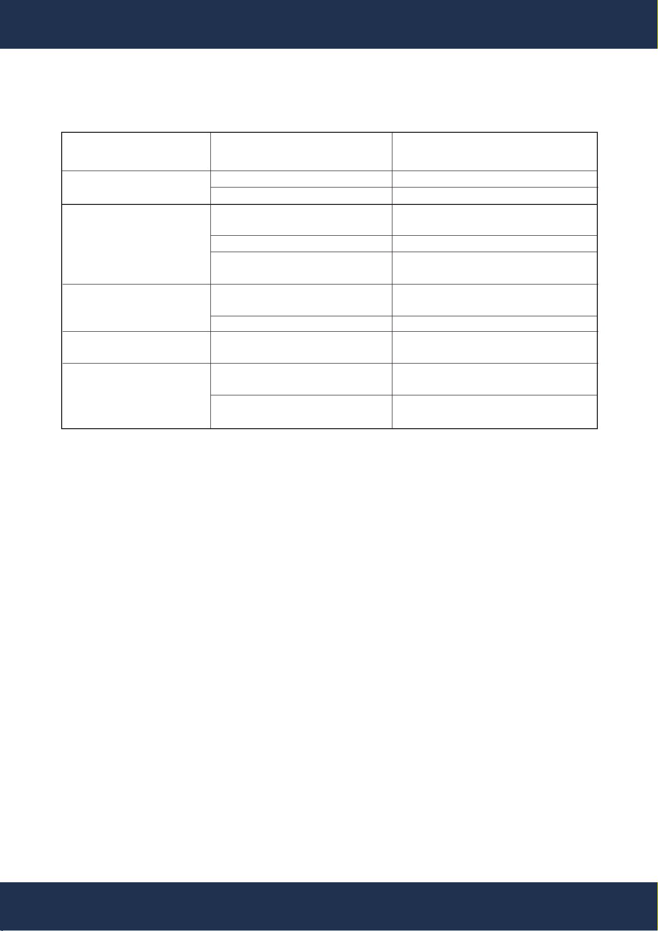
TROUBLESHOOTING
SALT CONCENTRATION AND POOL SETTINGS
Water Flow Protection: FLOW Red Light
▪ Cause: Pump stopped or valves closed
▪ Solution: Start the circulation pump, check for blockages, and open valves.
▪ Cause: Faulty flow switch or loose connections
▪ Solution: Replace the flow switch if the pump is on and the switch is closed.
High Salt Alert: HIGH Blue Light, GENERATING Bright Blue
▪ Cause: Excessive salt concentration
▪ Solution: Dilute by partially draining and refilling with fresh water.
Overcurrent Protection: HIGH Red Light, GENERATING Bright Green
▪ Cause: High salt concentration or generator blockage
▪ Solution: Clean the generator, check the salt level, and restart the system.
Low Salt Alert: LOW Blue Light
▪ Cause: Salt level below 700 PPM
▪ Solution: Add salt to the pool.
Low Current: LOW Red Light
▪ Cause: Extremely low salt level or circuit break
▪ Solution: Check the generator and salt level. Replace the generator if necessary,
especially if it's beyond its expected lifespan.
SITUATION
No LED Display
On the Panel
Chlorinate
Output is
Not Enough
Error Light On
Display Panel
Showing FL
Connections
Leaking
POSSIBLE CAUSE
No power supply
LED panel broken
Working time is not
enough
pH not normal
Chlorine loss as intense
sunlight exposure
Low water temperature
High water temperature
High salt salinity
The inlet / outlet of the
hose is clogged
The nut is not securely
tight
The connection fitting
is missing
SUGGESTION
Turn on the power switch
Contact the service center
Increase the working time
Keep pH 7.2 - 7.7
Put the pool shaded place
See Water Temperature
Detection
See Salt Salinity Detection
Clear the hose
Ensure the nut is tightened
Ensure all the fittings are
intact and in place
TROUBLESHOOTING
23
REPLACEMENT PARTS
REPLACEMENT PARTS
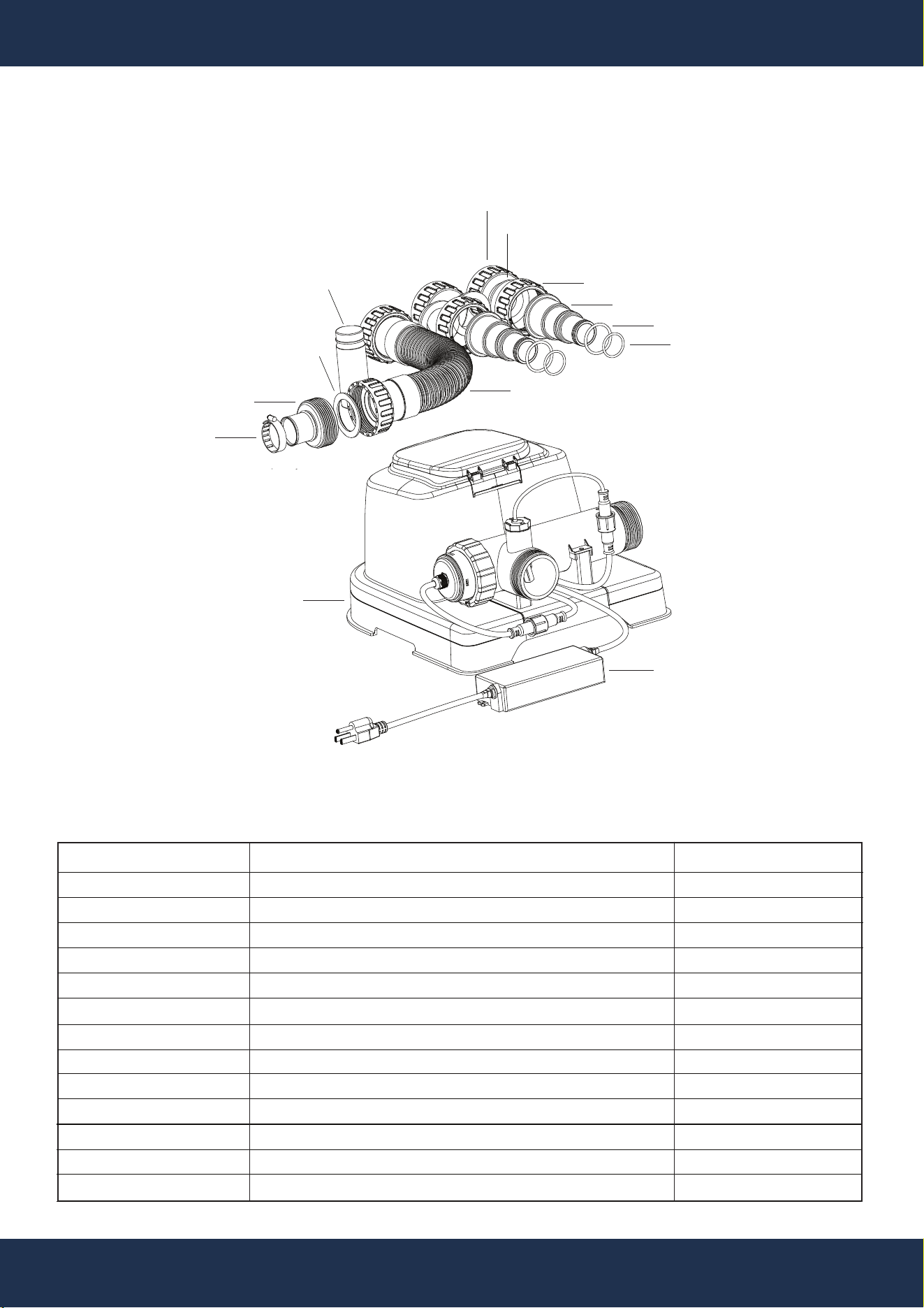
PARTS DIAGRAM
ITEM
1
2
3
4
5
6
7
8
9
10
11
12
13
DESCRIPTION
Control Box
Power Adapter
German-Style Hoop
38 to 32 Interface
Gasket
Reagents
Short Hose Connection Assembly
Water-Sealing Nut
T1-Sealing Gasket
Hose Nut
32/38 Hose Fitting
O-Ring
O-Ring
QTY
1
1
1
1
1
1
1
2
3
2
2
2
2
PARTS#: 2
PARTS#: 1
PARTS#: 3
PARTS#: 8
PARTS#: 9
PARTS#: 10
PARTS#: 4
PARTS#: 5
PARTS#: 6
PARTS#: 7
PARTS#: 12
PARTS#: 11
PARTS#: 13
PARTS LIST

24
DISCLAIMER
DISCLAIMER
PLEASE READ THE FOLLOWING CAREFULLY
The manufacturer and/or distributor have provided the parts list and assembly diagram in this
manual for reference purposes only. They do not make any representation or warranty to the buyer
that they are qualified to make repairs to the product or replace any parts of the product. In fact, the
manufacturer and/or distributor expressly state that all repairs and parts replacements should be
undertaken by certified and licensed technicians, and not by the buyer.
The buyer assumes all risk and liability arising from their repairs to the original product or
replacement parts or arising from their installation of replacement parts. It is strongly advised that
qualified professionals handle any repairs or replacements to ensure safety and proper functioning
of the product. Improper installation and operation may result in injury, property damage, or voiding
of warranty. The manufacturer and/or distributor shall not be held responsible for any accidents,
damages, or malfunctions resulting from the buyer's installation and operation of the product. It is
essential to follow all safety guidelines and recommendations provided in this manual and to seek
professional assistance if unsure about the installation or operation procedures.
CUSTOMER SERVICE
If you have any questions about ordering our pool pumps and replacement parts or pool products,
please feel free to contact us using the following contact information:
Customer Service and Technical Support
Phone: (909) 628-0880
Email: [email protected]
Hours of Operation: Monday – Friday, 9AM – 4PM (CST)