ERM ELECTRONIC SYSTEMS LTD
16 Hasar Shapira St. Rishon Lezion
7570418 Israel
Email: [email protected]
Tel: +972-3-9413313
TAGLINK BRIDGE
TECHNICAL MANUAL
Release 1.3
© Copyright 2024 by ERM Electronic Systems Ltd.


TagLINK Bridge Manual Rev-1.3 Page 3
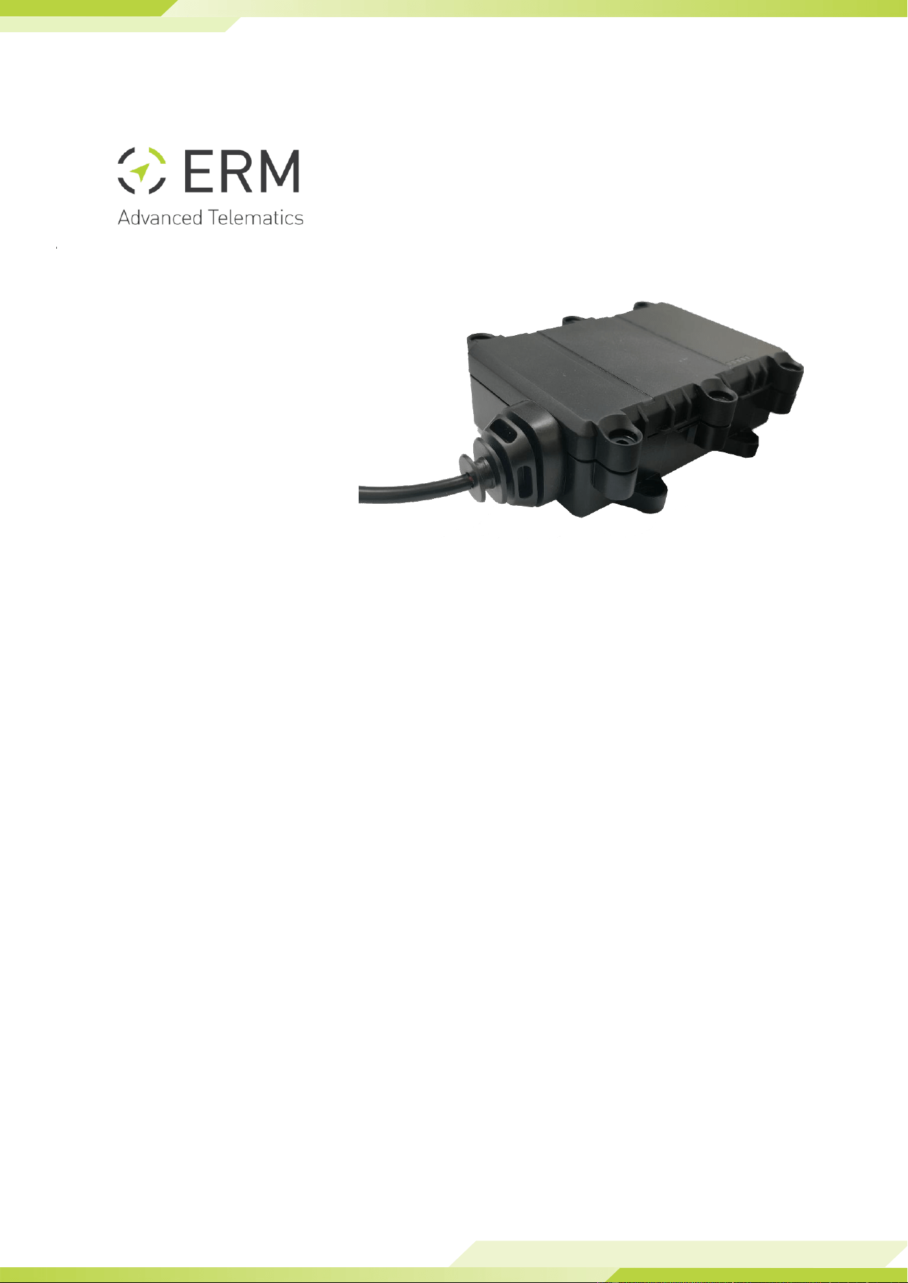
1. Product Description
The TagLINK Bridge is designed as an Automotive Bluetooth Bridge for Wiliot pixel
passive tags.
The TagLINK Bridge key features:
● Bluetooth v4.2 transceiver
● Embedded 360° RF antennas
● Internal backup battery – Optional
● 4 Pin automotive connector and Micro USB for external power
● Firmware & configuration update Over-The-Air (OTA)
1.1 Technical Specifications
Communication
BLE 4.2 module + Optimized antenna
Connectors
4-pin Molex connector, Micro USB
Power Supply
9-32VDC / USB
Backup battery
Optional - Rechargeable, 3.6V, 750mAh (Li-Poly or Li-ion)
Configuration/
Firmware Update
OTA
Operating temperature
0 to 45°C
Storage temperature
-20 to 80°C
Dimensions
10.8cm x 3.9cm x 8.7cm
Weight (NET)
65g
Durability
IP65
Max. relative humidity
90+/-5%
TagLINK Bridge Manual Rev-1.3 Page 4
2. Installation
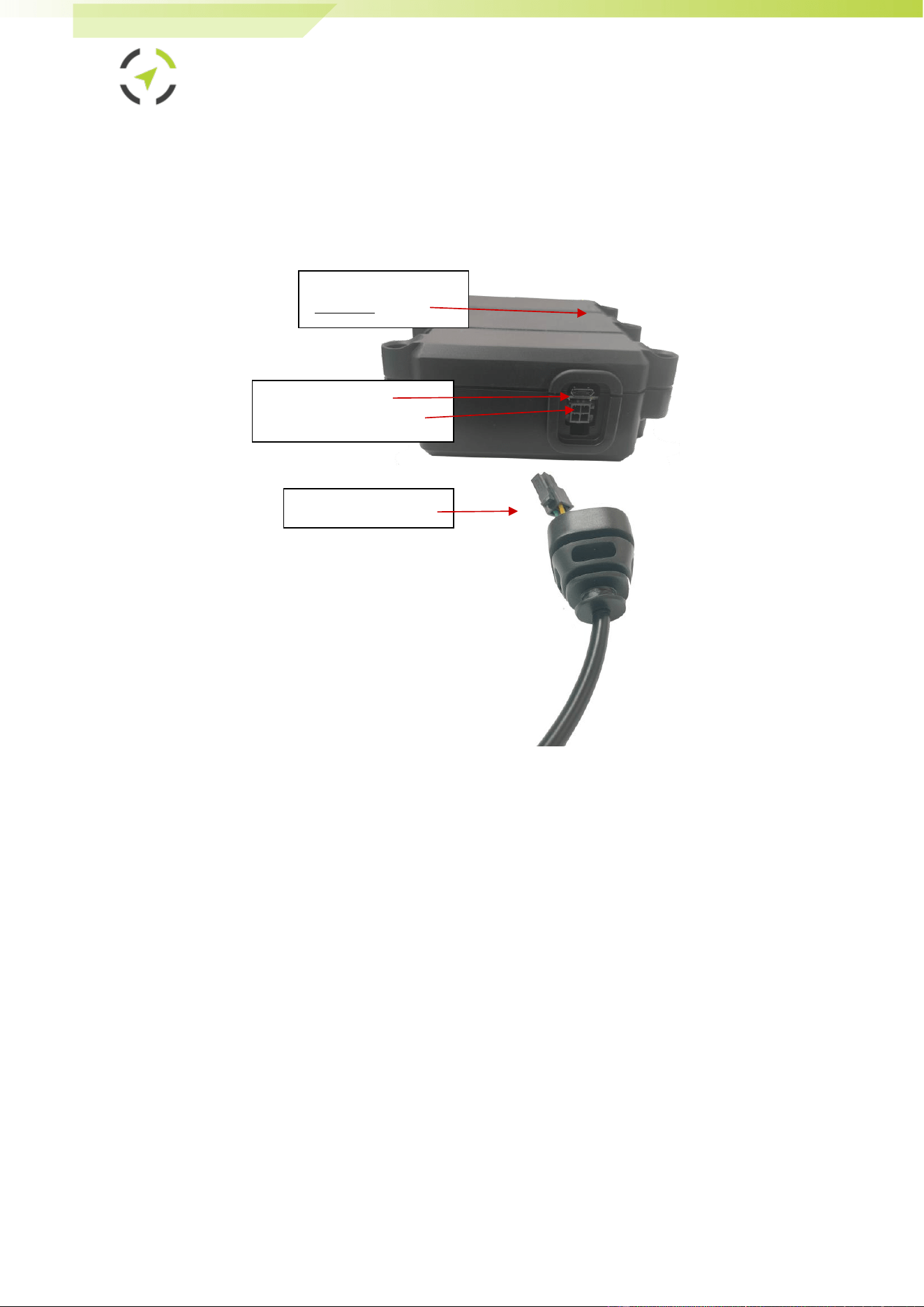
1. Unwrap the device wire harness but do not connect it to the device yet.
Refer to the following picture of the TagLINK Bridge connectors when
performing connections in the subsequent steps of this procedure.
2. If using the automotive type harness:
● Connect the red wire (pin #1) to positive 12/24v power (when
installation is in Vehicle - via a 3A fuse to the vehicle battery (+30)).
- In a vehicle installation, make sure this positive feed remains live
even when the Ignition switch is turned OFF and when starting the
engine. The fuse must be removed from the fuse housing during
installation.
● Connect the black wire (pin #5) to the ground (-) power (in vehicle
installation – to the vehicle chassis or any grounded part of the
vehicle).
- Make sure the connection is free of paint or dirt to assure a good
conductive ground connection
3. If using a Micro USB cable:
● Connect the Micro USB cable to the plug and the other side to a USB
power source.
Micro USB connector
4 Pin Automotive connector
Rubber seal and harness
LED Indicators
(Upper side)

TagLINK Bridge Manual Rev-1.3 Page 5
4. To finalize the installation, Identify the desired location in which to install
the device. Installation location should be clean, free of water, heat, and
large metallic objects. For the best reception, install the TagLINK Bridge in
an elevated position than the monitored elements.
5. Place the device in the selected location but do not affix it yet.
6. Secure the device in its preferred location. Remember, the flat bottom
side opposite the LEDs can be attached to any surface. Choose your
mounting method from the following options:
a. Double-sided adhesive sticker: This is the easiest option for
smooth, clean surfaces.
b. Cable ties: Thread cable ties through the designated holes (if
available) and fasten them securely to a suitable anchor point.
c. Screws: Use screws if a permanent and sturdy mounting is
necessary. Remember to choose screws appropriate for the
surface material and ensure they don't damage the device.
- Make sure the surface is clean and dry before using
adhesive stickers.
- For optimal signal reception, avoid mounting the device
directly on metal surfaces.
- Double-check that the device is level and securely attached
before use.
TagLINK Bridge Manual Rev-1.3 Page 6
3. Safety Instructions
● Personal safety is of paramount importance. Please follow all safety
instructions when installing ERM products
In a vehicle implementation:
- Always disconnect power when performing installation by removing the
negative connection of the vehicle battery. Never work when power is
connected.
- Always connect the positive wire using a 3A fuse.
- Reconnect the external power only after the installation is fully completed,
making sure all wires are safely insulated.
- Use appropriate work tools.
- Maintain good ventilation and lighting in the work area.
- Never leave bare wires. Trim all wires not in use in such a way that no bare
conductors remain, and fix them securely in place.
- Perform installation in a dry environment.
- Install ERM devices away from any heat sources.
- Do not install ERM devices in the engine compartment or on the vehicle’s
exterior.
- Install ERM devices away from large metallic bodies and never install them in
small gaps between metallic objects.
4. Troubleshooting
1. Device is Not Powering ON (No LED Indicator):
- Check Power Connection: Ensure the device is correctly connected to the
power source.
- Inspect Power Supply: Confirm the wires are properly connected: black
wire to GND, red wire to +12/24V, and green wire to IGN.
- If there's no voltage, consider using an alternate power source.
- Inspect for Damage: Verify the device does not show any signs of
physical damage.
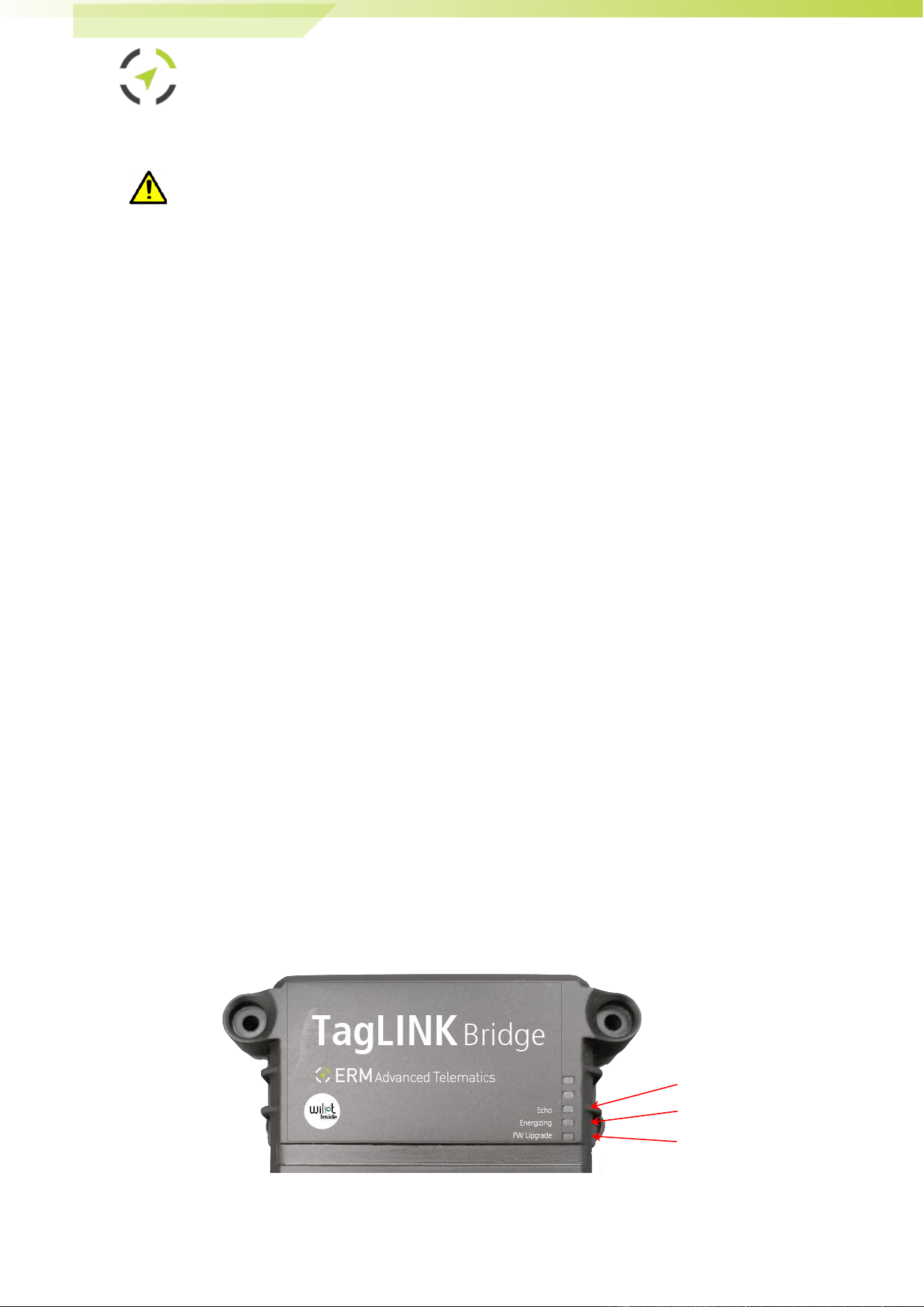
2. LED Indications:
Follow the below indications to better understand the situation:
Green LED
Red LED
Blue LED

TagLINK Bridge Manual Rev-1.3 Page 7
Blue LED (Echo LED) has the following blink patterns:
MODE
LED Activity
Description
Advertising Mode
First 30 seconds
from waking up
Bridge is advertising
Echoing Mode
Blinking, single
speed
Indicates the bridge has a tags packet in its
buffer (transmission queue). It means that
the bridge received Wiliot packets and
forwards them on.
Keep Alive Mode
Two fast blinks in
a row
Indicates the bridge is alive (sends beacons
management packets). When there is no
energizing and no packets to echo.
Red LED (Energizing LED) has the following blink patterns:
MODE
LED Activity
Description
Energizing Mode
ON, if
energizing is
configured
Indicates the bridge pattern includes
energizing mode.
OFF
Indicates the current pattern used does not
include energizing.
Dual Band &
Energies Energizing
Mode
Continuous
This mode will only be active if energizing
with Sub-1G.
Green LED (Firmware Upgrade LED) has the following blink patterns:
MODE
LED Activity
Description
Upgrade Mode
ON
Indicates the bridge firmware is being
upgraded.

TagLINK Bridge Manual Rev-1.3 Page 8
5. ERM Contact Information
ERM Advanced Telematics
16 Hasar Shapira Street, Rishon Lezion, 75704, Israel
Telephone: +972-(0)3-941-3313, Fax: +972-(0)3-941-3330
Web / Ticketing System: www.ermtelematics.com
Support email: suppo[email protected]

FCC warning statements:
This equipment has been tested and found to comply with the limits for a Class
B digital device, pursuant to part 15 of the FCC Rules. These limits are
designed to provide reasonable protection against harmful interference in a
residential installation. This equipment generates, uses and can radiate radio
frequency energy and, if not installed and used in accordance with the
instructions, may cause harmful interference to radio communications.
However, there is no guarantee that interference will not occur in a particular
installation. If this equipment does cause harmful interference to radio or
television reception, which can be determined by turning the equipment off and
on, the user is encouraged to try to correct the interference by one or more of
the following measures:
• Reorient or relocate the receiving antenna.
• Increase the separation between the equipment and receiver.
• Connect the equipment into an outlet on a circuit different from that to which
the receiver is connected.
• Consult the dealer or an experienced radio/TV technician for help.
Caution: Any changes or modifications to this device not explicitly approved
by manufacturer could void your authority to operate this equipment.
This device complies with part 15 of the FCC Rules. Operation is subject to the
following two conditions: (1) This device may not cause harmful interference,
and (2) this device must accept any interference received, including
interference that may cause undesired operation.
The device has been evaluated to meet general RF exposure requirement This
equipment complies with FCC radiation exposure limits set forth for an uncontrolled
environment.
This equipment should be installed and operated with minimum distance 20cm
between the radiator & your body.