
1
LinkTap
DT1 User Manual
1. Product Overview
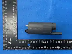
The LinkTap DT1 is a data transmission unit that connects to one wired sensor, such
as the LinkTap SP1S Wired Soil Sensor. The sensor takes measurements and sends
the data to the DT1, which then transmits it wirelessly to a LinkTap Gateway.
2. Safety Information
Small parts, including the battery cover, are a choking hazard. Keep them
away from children.
Use one 1.5 V AA alkaline or lithium battery. Do not use carbon-zinc, NiMH or
Ni-Cd batteries, and do not mix batteries of different types, brands or ages.
Observe polarity: the positive terminal faces the battery cover.
Do not recharge a non-rechargeable battery, and do not short-circuit,
puncture, crush, heat or incinerate a battery.
Remove the battery if the sensor will not be used for an extended period.
Leakage corrodes the electronics and voids the warranty.
If a battery has leaked, remove it with gloves, wipe the compartment with a
dry cloth, and do not reuse the sensor until it has been checked.
3. Setup
Before you start
You need:
2
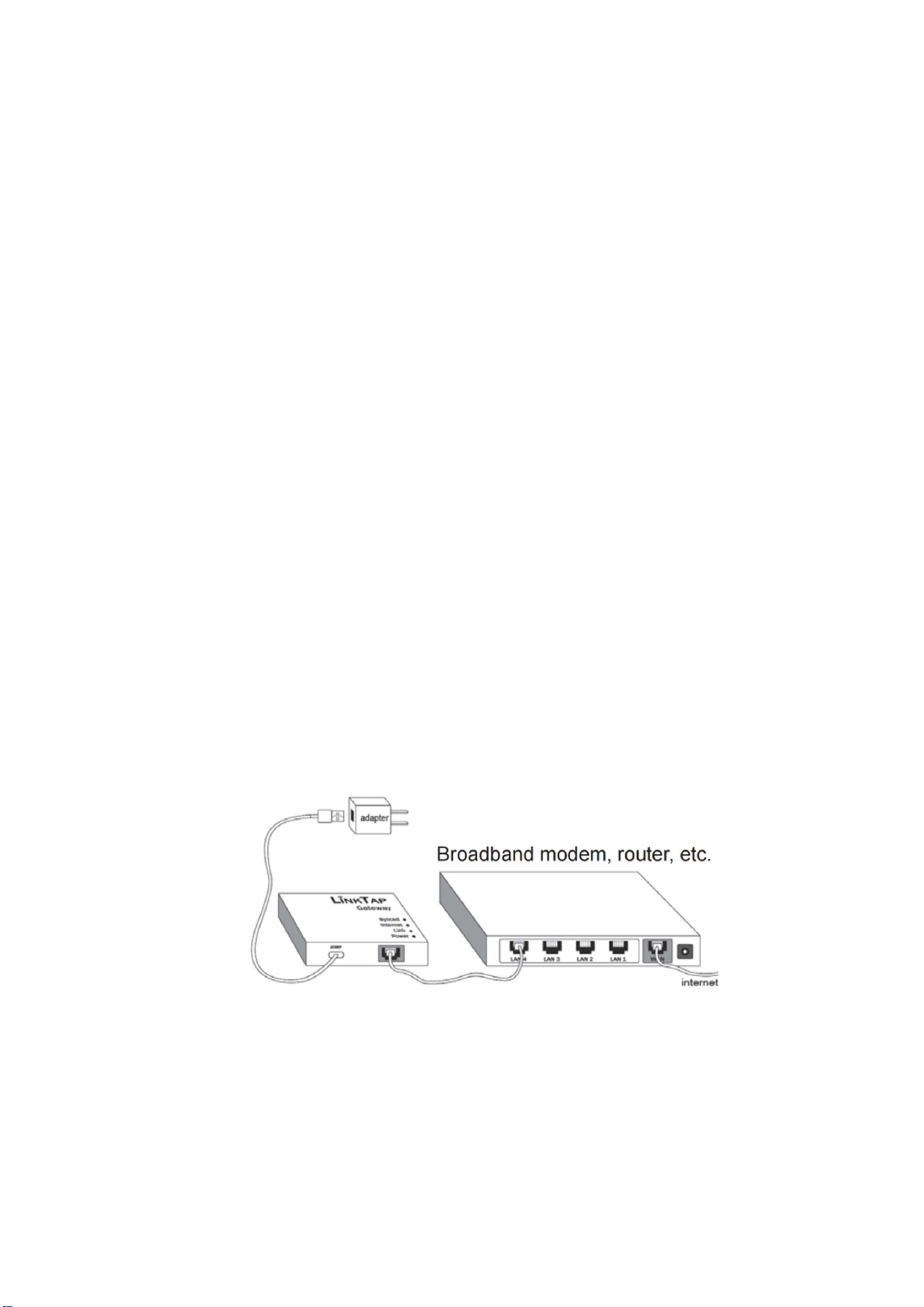
A powered LinkTap Gateway connected to your broadband router, and a
LinkTap account.
The LinkTap app (iOS, Android) or the web app at link-tap.com/signin.
One 1.5 V AA alkaline or lithium battery.
The DT1 uses the same LinkTap Gateway as LinkTap water timers and
ValveLinkers. One Gateway supports up to 15 devices in any combination — for
example 15 DT1, or 10 timers and 5 DT1. If you already have a LinkTap system in
the house, start at Step 3.
Step 1: Connect the Gateway
Use the supplied Ethernet cable to connect the LinkTap Gateway to any available LAN
port on your home broadband modem, router, network switch, or Wi-Fi repeater.
Then power the gateway using the supplied USB power cable and power adapter.
When all three gateway indicators — Power, Link, and Internet — turn solid green,
the gateway has successfully connected to the cloud server. This process usually
takes from 10 seconds to several minutes.
Note: To reduce possible wireless interference, place the LinkTap Gateway at least 60
cm away from power supplies and other electronic devices. Placing the gateway in a
higher location may help improve wireless coverage.
Step 2: Register the Gateway
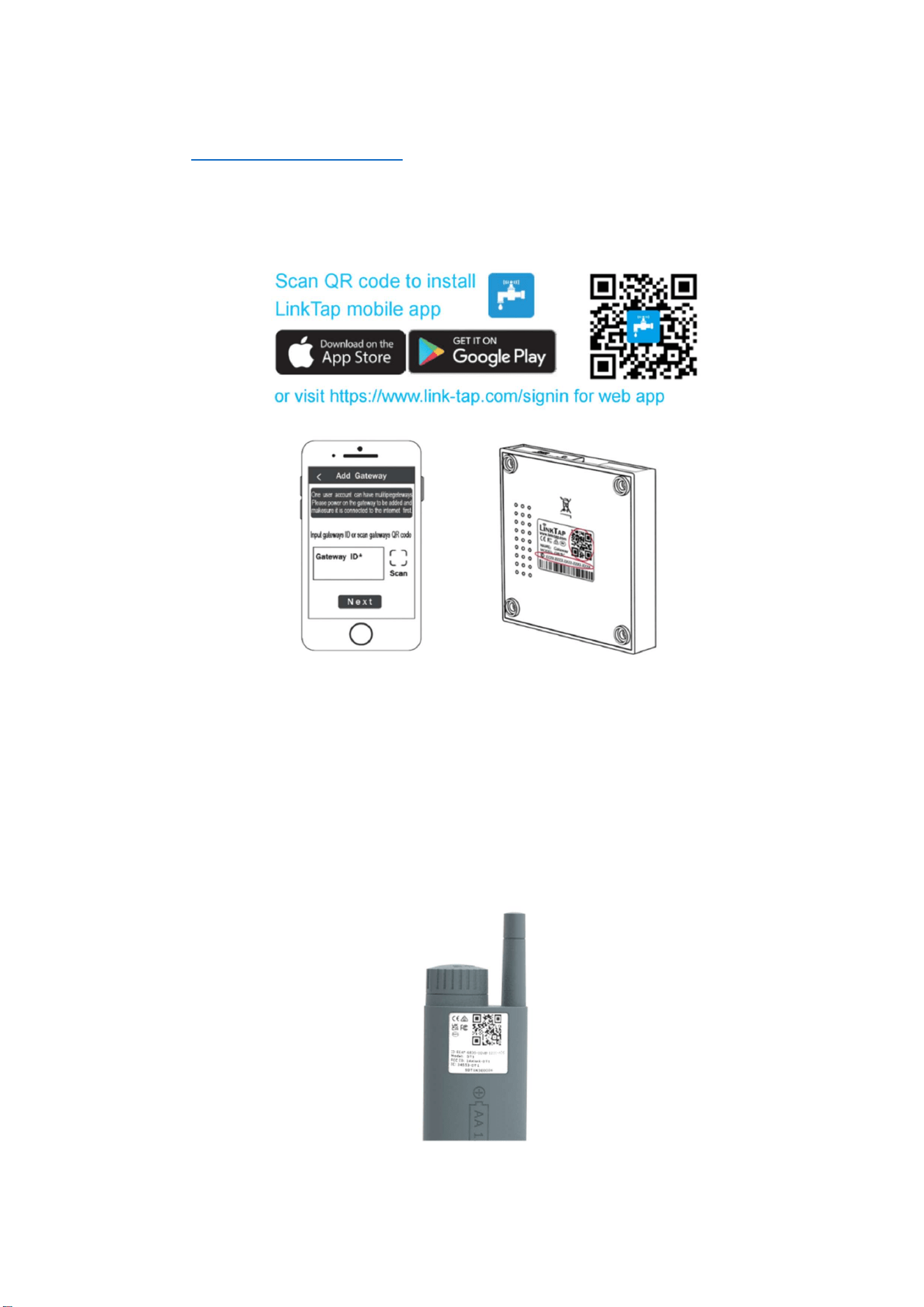
Use the free LinkTap mobile app or the LinkTap web app to register your user
3
account and gateway.
Web app: https://www.link-tap.com
After registration is complete, the Synced indicator on the gateway will turn solid
green.
Step 3: Add the DT1
In the LinkTap app, scan the QR code label on the DT1 to associate it with your
gateway.
After successful pairing, the newly added DT1 will appear in the sensor list in the
4
app.
Step 4: Install the battery
Use one 1.5V AA alkaline battery or one 1.5V AA lithium battery.
Do not use:
carbon-zinc batteries,
NiMH rechargeable batteries,
NiCd rechargeable batteries.
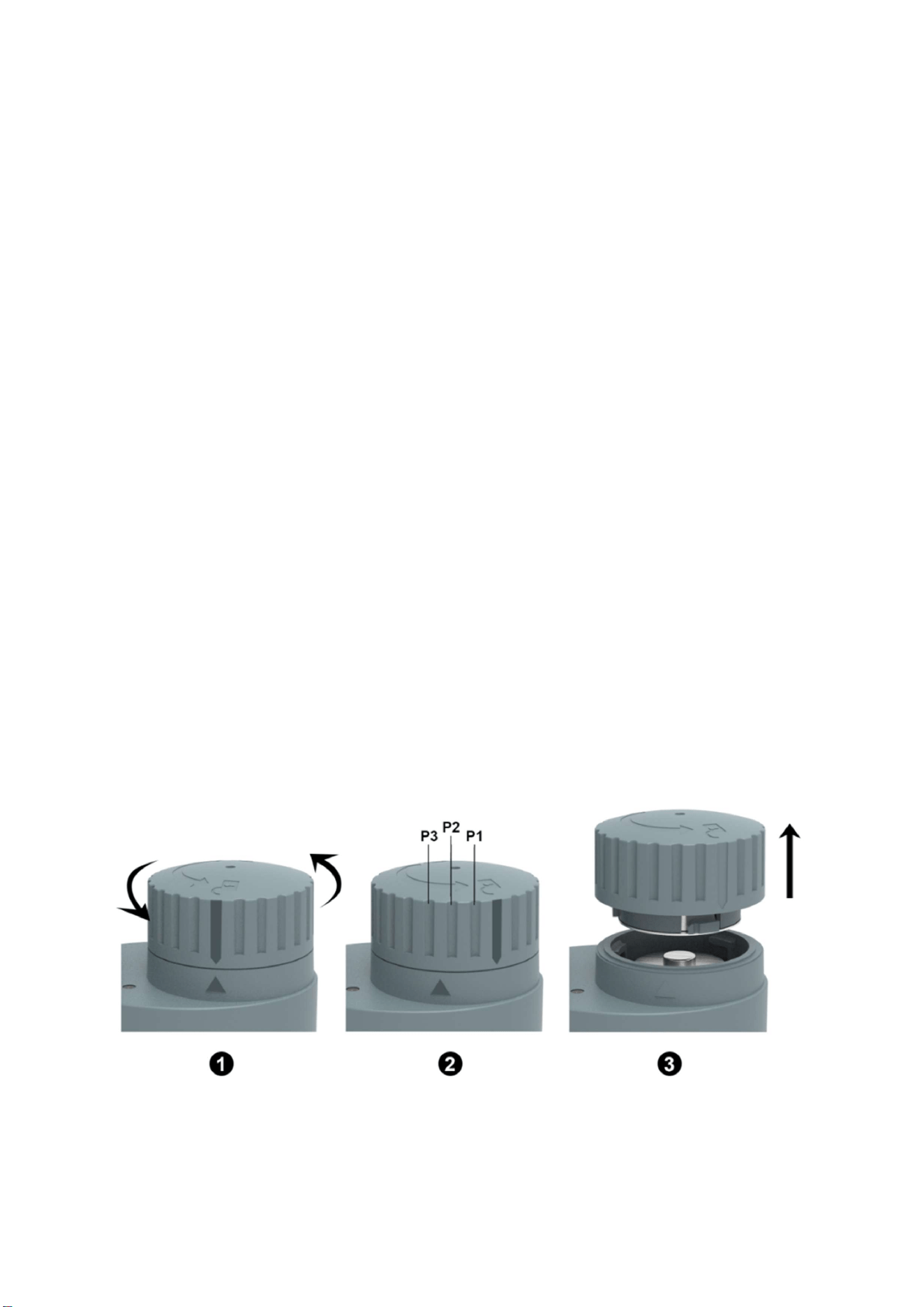
1. Open the Battery Compartment
Turn the battery compartment cover counterclockwise until the triangle alignment
mark on the device body is aligned between the P2 and P3 grooves on the battery
cover. The cover will then pop up automatically. Remove it.
2. Insert the Battery
Insert one 1.5V AA battery into the battery compartment in the correct direction:
3. Close the Battery Compartment
Align the area between the P2 and P3 grooves on the battery cover with the triangle
alignment mark on the device body, then put the cover back in place and press it
down. Rotate the cover clockwise until the long anti-slip groove is fully aligned with
the triangle mark. The cover is then fully locked.
After the battery is installed, the DT1 indicator will begin flashing green as it starts
connecting to the gateway. This process usually takes about 1 minute.
5
When the indicator remains solid green, the DT1 has successfully connected to the
gateway.
To save battery power, the indicator will automatically turn off after 15 seconds.
Step 5: Install the DT1 in a Suitable Location
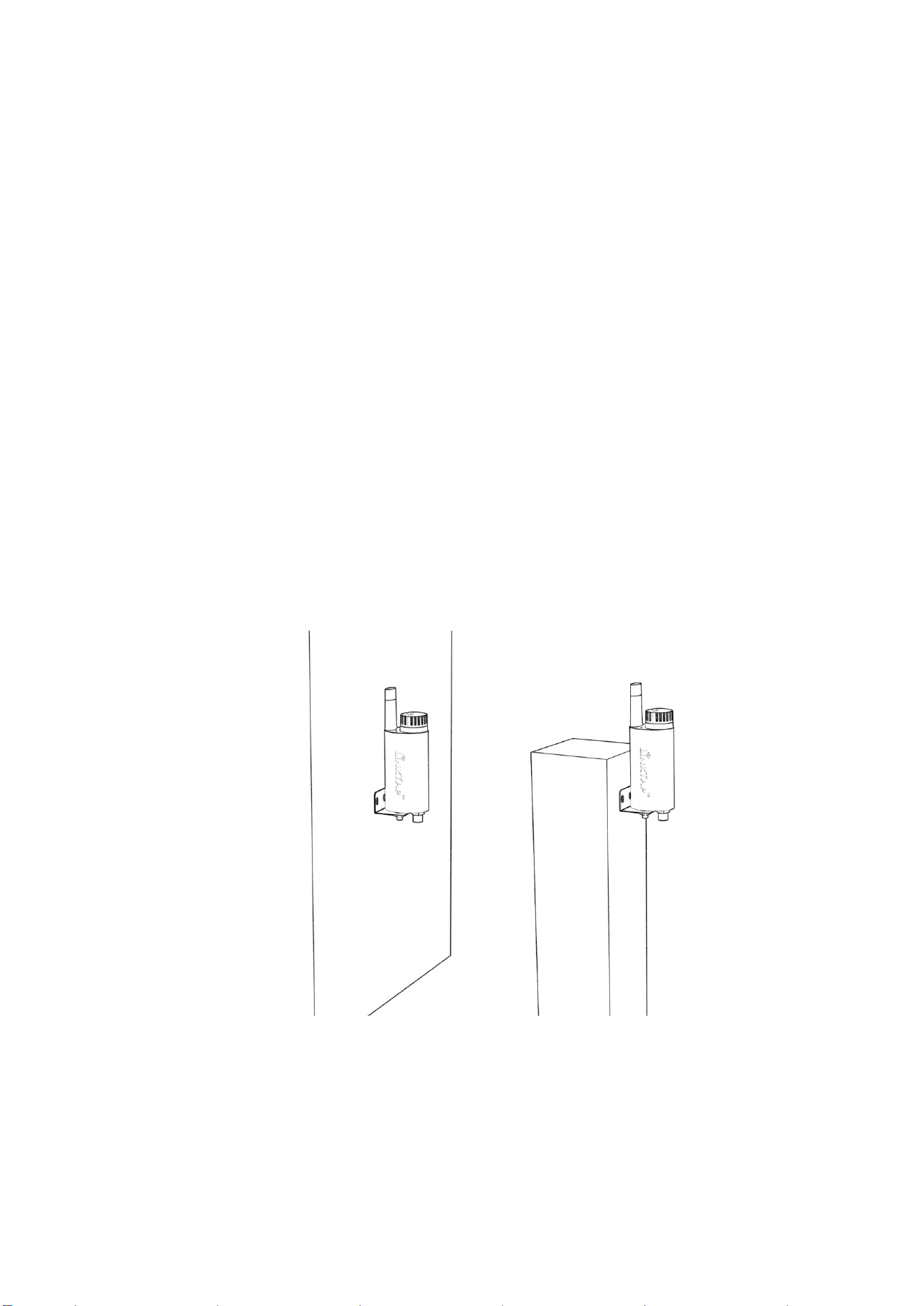
The DT1 can be installed on a wall or a wooden stake. To ensure stable wireless
communication between the DT1 and the gateway, follow these recommendations:
Install the DT1 at least 60 cm above the ground.
Avoid obstructions such as metal structures, water tanks, Low-E glass, and
dense foliage.
To maintain waterproof performance:
Keep the power switch and connectors facing downward.
Install the device vertically.
Step 6: Connect the SP1S Soil Sensor to the DT1
6
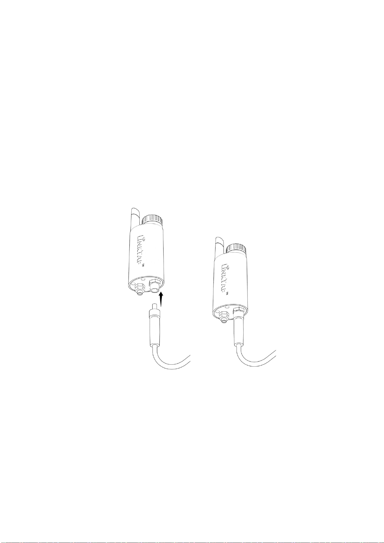
Insert the connector of the soil sensor cable fully into the Sensor port of the DT1 and
tighten it securely.
⚠ Note
The DT1’s Sensor port is keyed. Align the notch carefully before insertion. Do not
force it, as this may damage the connector.
Also prevent foreign matter from entering the Sensor port, as this may cause
abnormal sensor connection behavior.
After the connection is completed, information for the SP1S soil sensor will appear in
the sensor list under the DT1 in the app within 10 minutes at most.
Tip
To reduce power consumption, the DT1 periodically checks the connection status of
7
the SP1S. Therefore, after connecting the sensor, it may take up to 10 minutes
before its status and data appear in the app.
If you want to speed up the process, you can use either of the following methods:
Method 1: Tap Find Sensor under Device Settings for the DT1.
Method 2: Unscrew and reinstall the battery cover to restart the DT1.
If the sensor still does not appear as expected, please refer to the troubleshooting
section or visit the official FAQ: www.link-tap.com/faq
4. Status Indicator Definitions
The DT1 is equipped with a dual-color LED indicator, which shows the device
working status through different colors and flashing patterns.
Device
Operating Stage
Indicator Status
Meaning
From startup until
successfully
connecting to the
gateway
Flashes red once,
then flashes
green once
Startup self-check completed; the device
has powered on and the LED is
functioning normally.
Flashes red once,
then flashes
green once (or
may not flash
Battery level is too low and the system
cannot complete the startup process.
8
green), then turns
off
Flashes red for 15
seconds, then
starts flashing
green
Battery level is low. The system can still
start, but it can no longer maintain
normal sensor operation. Replace the
battery as soon as possible.
Continues
flashing red for
more than 15
seconds
Battery is depleted and the system
cannot operate normally.
After successfully
connecting to the
gateway
Solid green for 15
seconds, then
turns off
Connected to the gateway and
operating normally.
5. Specifications
Dimensions 43 mm (L) × 34 mm (W) × 120 mm (H)
Power Supply 1 × 1.5V AA battery (alkaline / lithium)
Battery Life
More than 10 months
* Tested in a laboratory environment using factory default
parameters.
Operating
Temperature
Operating temperature: -31°C to 60°C
Protection Rating IP66
Wireless Range Up to 200 m, line of sight

9
Wireless
Frequency
2.4 GHz ISM band
Wireless Security AES-256 encryption
6. Warranty, Disclaimer, and Support
6.1 Limited Warranty
LinkTap provides a limited warranty for this product against defects in materials and
workmanship under normal residential use.
The warranty period is: 1 years from the date of original purchase.
During the warranty period, LinkTap will, at its discretion, repair or replace the
defective product or defective component free of charge, provided that the product
has been used, installed, and maintained in accordance with this user manual.
To obtain warranty service, proof of purchase may be required.
6.2 Warranty Coverage
This limited warranty covers defects caused by:
Manufacturing defects
Material defects
Failure of electronic components under normal use
Defects occurring during normal installation and operation as described in this
manual
Replacement products or parts may be new, refurbished, or functionally
equivalent, subject to local laws and LinkTap’s warranty policy.
6.3 Warranty Exclusions
This warranty does not cover damage or malfunction caused by:
Improper installation, misuse, abuse, neglect, or unauthorized modification
Failure to follow the instructions in this user manual
Use of incorrect batteries, mixed batteries, rechargeable batteries where not

10
recommended, or leaking batteries
Incorrect external power supply voltage, polarity, or wiring
Physical damage, impact, dropping, crushing, or excessive force
Bent, broken, corroded, or damaged sensor probes
Water ingress caused by incorrect installation direction, loose covers, damaged
seals, or improperly tightened connectors
Damage caused by insects, animals, rodents, or plant roots
Damage caused by extreme weather, lightning, flooding, fire, frost, freezing, or
other natural events
Exposure to chemicals, fertilizers, pesticides, solvents, corrosive substances, salt
spray, or contaminated environments beyond normal garden use
Normal wear and tear
Consumable parts, including batteries
Signal problems caused by building structures, wireless interference, network
issues, gateway placement, or Internet service interruptions
Use in commercial, industrial, agricultural production, or safety-critical
applications unless expressly approved by LinkTap
This warranty also does not cover any labor cost, removal cost, reinstallation cost,
travel cost, shipping cost, or any indirect cost unless required by applicable law.
6.4 Disclaimer
This product is designed to provide environmental monitoring data to assist with
garden irrigation management. It is not intended to be used as a precision laboratory
instrument, safety device, medical device, or the sole basis for critical irrigation,
agricultural, environmental, or property-protection decisions.
Soil moisture, soil temperature, EC, air temperature, and air humidity readings may
be affected by many external factors, including but not limited to:
Soil type and soil structure
Soil compaction and air gaps around the probes
Installation depth and position
Root distribution
Stones, metal objects, fertilizer granules, or organic matter near the probes
Local salinity and fertilizer concentration
Soil temperature variation
Sensor aging, contamination, or corrosion
Wireless communication conditions
Gateway and Internet connectivity
App configuration and firmware version
Therefore, measurement data should be used as a reference for irrigation decisions
and should not be considered an absolute guarantee of soil or plant condition.
Users are responsible for verifying that the product is suitable for their specific
application and local environmental conditions.

11
6.5 Limitation of Liability
To the maximum extent permitted by applicable law, LinkTap shall not be liable for
any direct, indirect, incidental, consequential, special, or punitive damages arising
from the use or inability to use this product.
This includes, but is not limited to:
Plant damage or plant death
Lawn, garden, greenhouse, or landscape damage
Water loss, overwatering, or underwatering
Soil nutrient imbalance or fertilizer-related loss
Property damage
Loss of data
Loss of revenue, profit, or business opportunity
Costs related to inspection, removal, replacement, or reinstallation
Network, Internet, cloud service, or third-party platform interruptions
The total liability of LinkTap, if any, shall not exceed the original purchase price paid
for the product.
6.6 User Responsibility
The user is responsible for:
Installing the product correctly according to this manual
Selecting the appropriate soil type in the app
Checking sensor readings after installation
Maintaining proper soil contact around the probes
Keeping connectors clean and properly tightened
Replacing battery when required
Ensuring safe cable routing to prevent tripping hazards
Confirming that the gateway, network, and app remain operational
Monitoring irrigation results and plant condition regularly
This product is intended to assist irrigation management, but it does not replace
regular inspection of plants, soil, irrigation equipment, and local weather conditions.
6.7 Product Updates and App Changes
LinkTap may update product firmware, app functions, cloud services, user interface
designs, and documentation from time to time to improve performance, reliability, and
user experience.
Descriptions, screenshots, features, and functions in this manual may differ from the

12
actual app or product firmware version.
For the latest instructions, please refer to:
LinkTap App
Official FAQ: www.link-tap.com/faq
Device Health Check Tool: www.link-tap.com/health
Web App: https://www.link-tap.com
6.8 Support
For warranty service, troubleshooting assistance, or product support, please contact
LinkTap after-sales support ([email protected]) or visit the official website.
When contacting customer support, please provide:
Product model
App account information
A description of the issue
Photos or videos showing the installation, wiring, sensor position, and indicator
status, if applicable
FCC Statement
Changes or modifications not expressly approved by the party responsible for
compliance could void the user's authority
to operate the equipment.
This equipment has been tested and found to comply with the limits for a Class B digital
device, pursuant to Part 15 of
the FCC Rules. These limits are designed to provide reasonable protection against
harmful interference in a
residential installation. This equipment generates uses and can radiate radio frequency
energy and, if not installed and
used in accordance with the instructions, may cause harmful interference to radio
communications. However, there is no
guarantee that interference will not occur in a particular installation. If this equipment
does cause harmful
interference to radio or television reception, which can be determined by turning the
equipment off and on, the user is
encouraged to try to correct the interference by one or more of the following measures:
-- Reorient or relocate the receiving antenna.
-- Increase the separation between the equipment and receiver.
-- Connect the equipment into an outlet on a circuit different from that to which the
receiver is connected.
-- Consult the dealer or an experienced radio/TV technician for help
This device complies with part 15 of the FCC rules. Operation is subject to the following
two conditions (1)this device
may not cause harmful interference, and (2) this device must accept any interference
received, including interference
that may cause undesired operation.
This equipment complies with FCC radiation exposure limits set forth for an
uncontrolled environment. This

13
equipment should be installed and operated with minimum distance 20cm between the
radiator & your body.
IC statement
This device contains licence-exempt transmitter(s)/receiver(s) that comply with
Innovation, Science
and Economic DevelopmentCanada’s licence-exempt RSS(s). Operation is subject to the
following
two conditions:
(1) This device may not cause interference.
(2) This device must accept any interference, including interference that may cause
undesired
operation of the device.
The term “IC: “ before the certification/registration number only signifies that the
Industry Canada
technical specifications were met.
This product meets the applicable Industry Canada technical specifications.
Cet appareil contient des émetteurs / récepteurs exemptés de licence conformes aux
RSS (RSS)
d'Innovation, Sciences etDéveloppement économique Canada. L'exploitation est
autorisée aux
deux conditions suivantes : (1) l'appareil ne doit pasproduire de brouillage,et (2)
l'utilisateur de
l'appareil doit accepter tout brouillage radioélectrique subi, même si le brouillage est
susceptible
d'en compromettre le fonctionnement.
L'émetteur/récepteur exempt de licence contenu dans le présent appareil est conforme
auxCNR
d'Innovation, Sciences et Développement économique Canada applicables aux
appareils radio
exempts de licence.
L'exploitation est autorisée aux deux conditions suivantes :
1)L'appareil ne doit pas produire de brouillage;
2)L'appareil doit accepter tout brouillage radioélectrique subi, même si le brouillage est
susceptible
d'en compromettre lefonctionnement.
This transmitter must not be co-located or operating in conjunction with any other
antenna
ortransmitter. This equipment should be installed and operated with a minimum
distance of
20centimeters between the radiator and your body.
Cet émetteur ne doit pas être Co-placé ou ne fonctionnant en même temps qu'aucune
autre
antenne ouémetteur. Cet équipementdevrait être installé et actionné avec une distance
minimum
de 20 centimètres entre le radiateur et votre corps.