
E3981
Rev F 2/2/24
Engineering and technical data are subject to change without notice.
FEDERAL INDUSTRIES 215 Federal Ave Belleville, WI 53508
INSTALLATION & OPERATIONS INSTRUCTIONS
VHSS: Heated Models

E3981 VHSS 2
CONTENTS
(1) Introduction ............................................................................................................................................................. 3
1.1 Serial Number ................................................................................................................................................ 3
(2) Warning Labels & Safety Instructions ..................................................................................................................... 4
(3) PRIOR TO UNPACKING EQUIPMENT! ................................................................................................................. 5
(4) General Electrical & Grounding .............................................................................................................................. 6
4.1 Cord Connected ............................................................................................................................................. 6
(5) Installation Instructions ........................................................................................................................................... 7
5.1 Locating The Display Case ............................................................................................................................ 7
5.2 Removing Case From Shipping Skid ............................................................................................................. 7
5.3 Single Case Installation (Stand alone units) .................................................................................................. 8
5.4 Prior to Initial Use ........................................................................................................................................... 9
(6) Joining kit installation (VHSS to VHSS) ................................................................................................................ 10
6.1 Installation for joined cases (Lineups) .......................................................................................................... 10
(7) Feature Overview .................................................................................................................................................. 13
(8) Shelving Installation and Removal ........................................................................................................................ 14
8.1 Shelf Brackets and Supports........................................................................................................................ 14
(9) SLIDE-IN LEG & CASTER ADJUSTMENTS ........................................................................................................ 17
(10) Control Operation ............................................................................................................................................. 19
(11) Food Packaging Recommendations ................................................................................................................ 21
(12) Cleaning Instructions ........................................................................................................................................ 22
12.1 Daily Cleaning .............................................................................................................................................. 22
12.2 Weekly Cleaning .......................................................................................................................................... 22
(13) Service .............................................................................................................................................................. 24
(14) Sale & Disposal ................................................................................................................................................ 25
14.1 Owner Responsibility ................................................................................................................................... 25
(15) Troubleshooting ................................................................................................................................................ 26
(16) Wiring Diagrams ............................................................................................................................................... 27
16.1 VHSS2460, VHSS3660, VHSS4860, VHSS2478, VHSS3678 .................................................................... 27
16.2 VHSS4878 .................................................................................................................................................... 28
(17) VHSS Service Parts ......................................................................................................................................... 29
(18) Options ............................................................................................................................................................. 32
18.1 Rear Swinging Door ..................................................................................................................................... 32
18.2 Rear Sliding Doors ....................................................................................................................................... 33
E3981 VHSS 3
(1) INTRODUCTION
Thank you for purchasing a Federal Industries display case. This manual contains important
instructions for installing and servicing your new display case. A repair parts list and wiring
diagram are also included in the manual. Read all of these documents carefully before installing
or servicing your case.
NOTICE
Read this manual before installing your case. Keep this manual and
refer to it before doing any service on the equipment. Failure to do so
could result in personal injury or damage to the case.
NOTICE
Installation and service of the electrical components in the case must
be performed by a licensed electrician.
The portions of this manual covering components contain technical
instructions intended only for persons qualified to perform electrical
work.
DANGER
Improper or faulty hookup of electrical components in the case can
result in severe injury or death.
All electrical wiring hookups must be done in accordance with all
applicable local, regional, or national standards.
1.1 SERIAL NUMBER
Record the model and serial numbers of the case for easy reference. Always refer to both model
and serial numbers in your correspondence with Federal regarding the case.
Case Model__________________________ Serial Number______________________
This manual cannot cover every installation, use, or service situation. If you need additional
information, call or write us:
WARRANTY/TECHNICAL SERVICE DEPARTMENT
Parts Town
1200 Greenbriar Dr.
Addison, IL 60101
Toll Free: (833) 238-8168
Email: [email protected]
E3981 VHSS 4
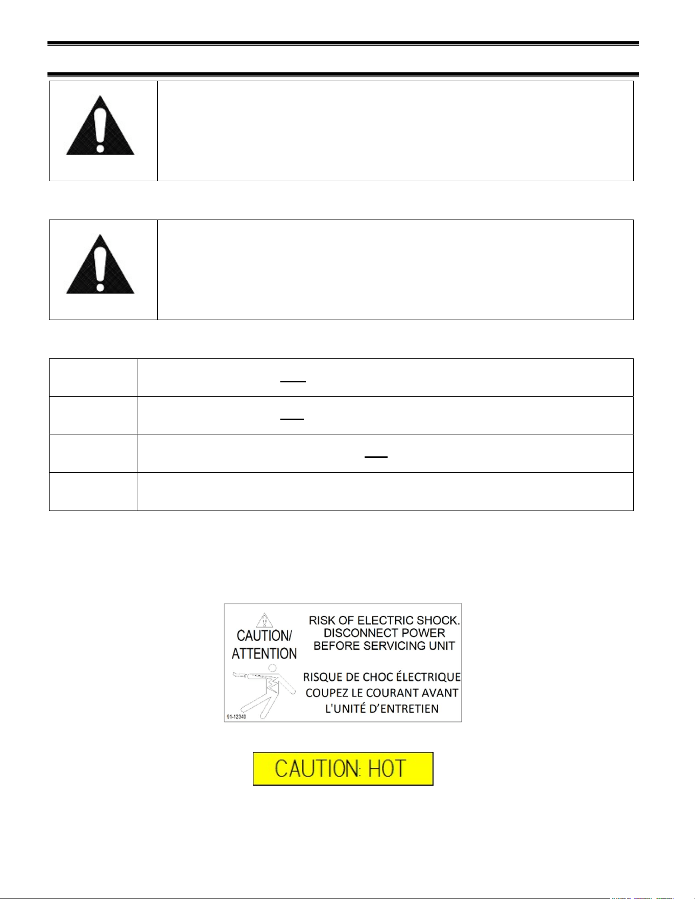
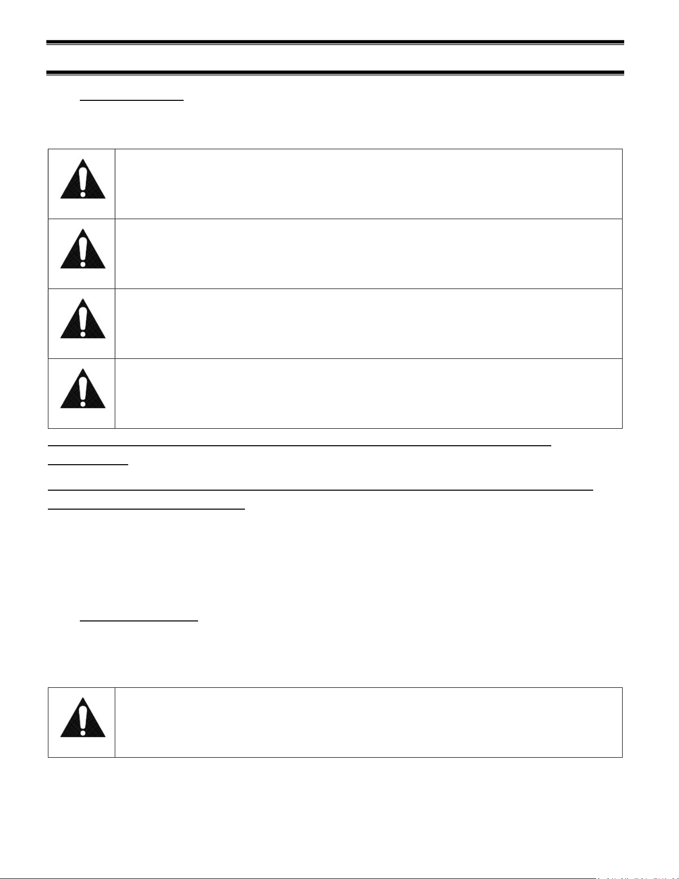
(2) WARNING LABELS & SAFETY INSTRUCTIONS
This is the safety-alert symbol. When you see this symbol on your
case or in the manual, be alert to the potential for personal injury or
damage to your equipment.
Be sure you understand all safety messages and always follow recommended precautions and
safe operating procedures.
NOTICE TO EMPLOYERS:
You must make sure that everyone who installs, uses, or services your
case is thoroughly familiar with all safety information and procedures.
Important safety information is presented in this section and throughout the manual. The
following signal words are used in the warning and safety messages:
DANGER: Severe injury or death will occur if you ignore the message.
WARNING: Severe injury or death can occur if you ignore the message.
CAUTION: Minor injury or damage to your case can occur if you ignore the message.
NOTICE:
This is important installation, operation, or service information. If you ignore the
message, you may damage your case.
The warning and safety labels shown throughout this manual are placed on your Federal
Industries case at the factory. Follow all warning label instructions. If any warning or safety labels
become lost or damaged, call our customer service department at (800) 356-4206 for
replacements.
Located at front of unit and on shelves

E3981 VHSS 5
(3) PRIOR TO UNPACKING EQUIPMENT!
Inspect for shipping damage.
You are responsible for filing all freight claims with the delivering truck line. Inspect all
cartons and crates for damage as soon as they arrive. If damage is noted to shipping crates,
cartons, or if a shortage is found, note this on the bill of lading (all copies) prior to signing.
If damage is discovered when the case is uncrated, immediately call the delivering truck line
and follow-up the call with a written report indicating concealed damage to your shipment.
Ask for an immediate inspection of your concealed damaged item. Crating material must be
retained to show the inspector from the truck line.
E3981 VHSS 6
(4) GENERAL ELECTRICAL & GROUNDING
WARNING:
Improper or faulty hookup of electrical components in the display case
can result in severe injury or death.
4.1 CORD CONNECTED
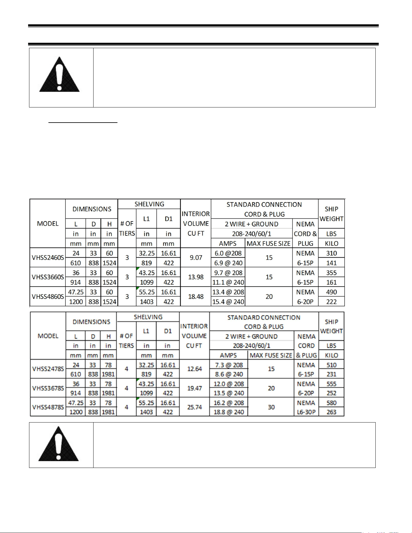
All standard models are supplied with a power cord that is properly sized to the amperage
requirements of the case. See the rating plate for specific unit requirements. This can be
located as shown in the “FEATURE IDENTIFICATION” section of this manual.
The cord is factory installed protruding from the bottom rear corner of the case.
A separate circuit for each display case is required to prevent other appliances on the
same circuit from overloading the circuit and causing malfunction.
CAUTION
Risk of Electric Shock. If the cord or plug becomes damaged, replace
only with a cord and plug of the same type.
E3981 VHSS 7
(5) INSTALLATION INSTRUCTIONS
5.1 LOCATING THE DISPLAY CASE
The case(s) should be located where it is not subjected to the direct rays of the sun, heating
ducts, grills, radiator, or ceiling fans, nor should it be located near open doors or main door
entrances. Also, avoid locations where there is excessive air movement or air disturbances and
avoid high humidity locations such as near cases with water misting or fogging devices. Failure
to locate this case as stated will reduce the performance of your display and will affect
temperature of interior of case and product.
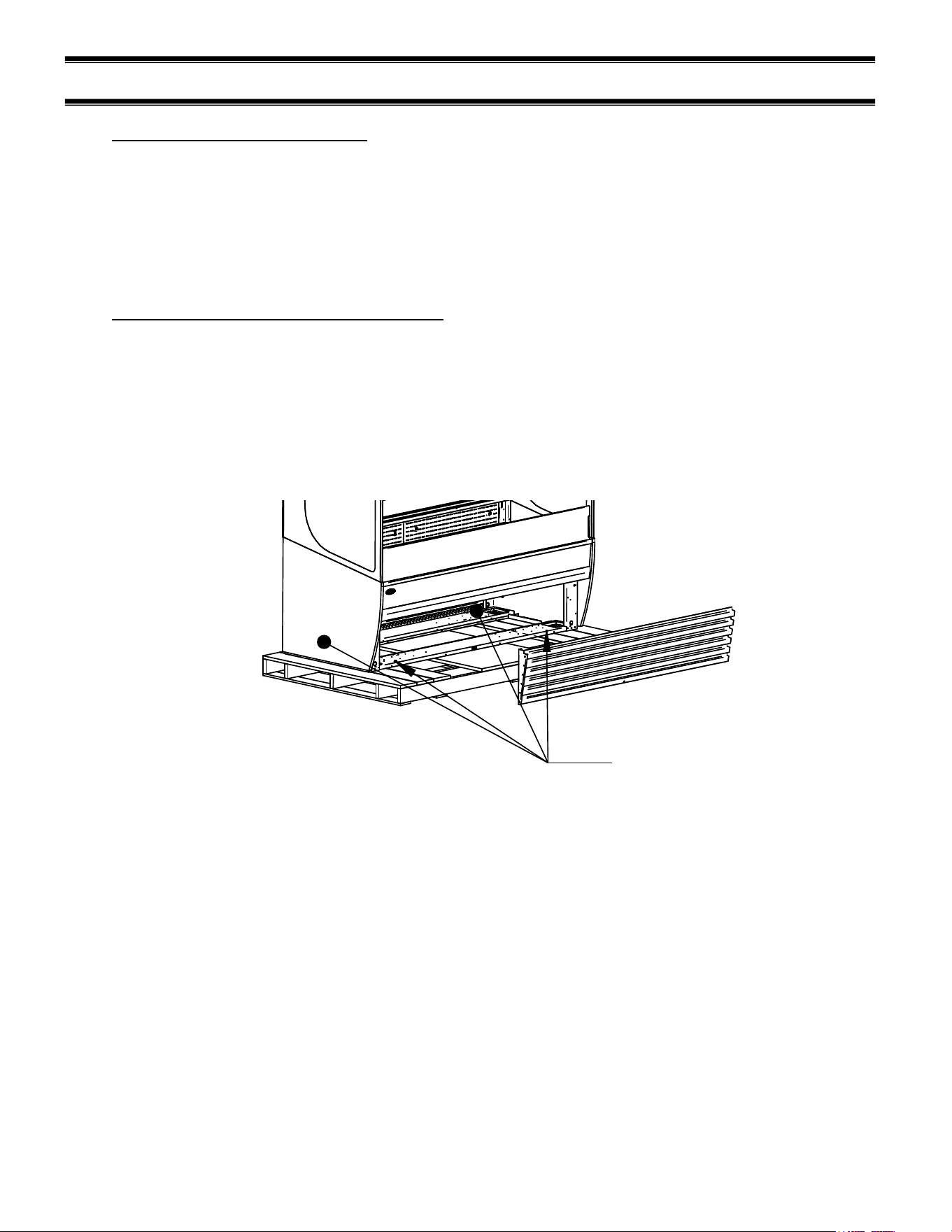
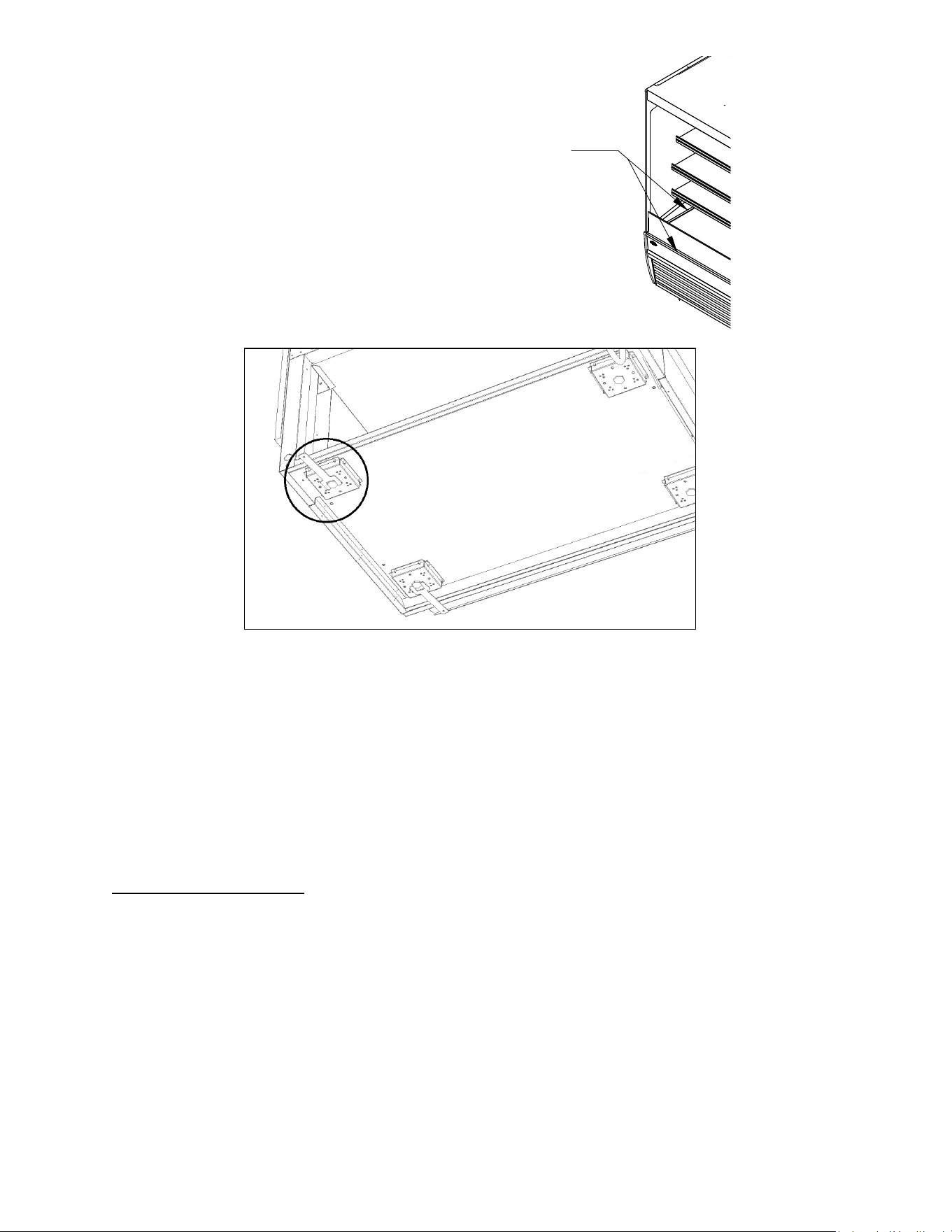
5.2 REMOVING CASE FROM SHIPPING SKID
Be sure to leave shelf packaging material intact for this step.
First remove the base front and rear panels
Two or more people should be involved in moving the unit from the pallet onto the ground.
Remove the (4) 1/4” screws that secure the case to the skid. These screws are located in the
front and rear corners of the base rails. Base front and rear panels must be removed to access
these bolts.
LAG BOLT
LOCATIONS
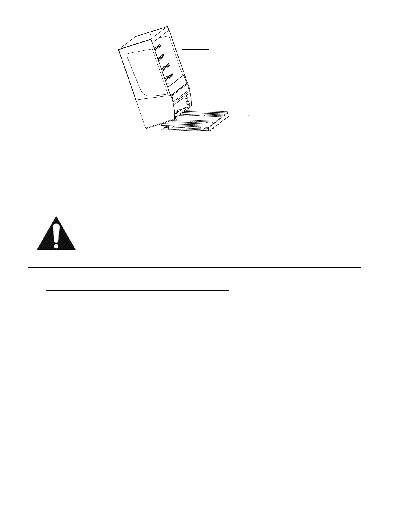
Once all the bolts are removed, slide the unit off the back of the shipping pallet, and tilt it so the
rear corner touches the ground. Then have someone move pallet out from under the case and
gently tilt the case forward until it touches the floor.
NOTE: see page 18 for removal of slide-in cases from pallet.
E3981 VHSS 8
REMOVE CASE OFF OF FRONT OR BACK OF SKID ONLY
PULL SKID AWAY FROM CASE
AND GENTLY SET CASE ON FLOOR
5.2.1 Removing Packaging Material
Remove bubble wrap and packing material for all shelves and panel, brackets, etc. If it is
necessary to remove tape residue from plastic materials, use cleaning compounds
recommended in the cleaning section of this manual.
5.2.2 Lifting and Moving the Case
Caution:
Do not push or pull against the glass air deflector on front of case. Doing
so can cause the glass to break. Do not push or pull on side glass or pull
on base panel. Doing so will break glass or pull out panel mounting
screws. Care must be taken not to damage the case when removing it
from the skid or moving the case.
5.3 SINGLE CASE INSTALLATION (STAND ALONE UNITS)
Leveling the Case
A wrench is included to aid in adjusting leg levelers.
Check the left-to-right level of the case along front of plastic air deflector retainer.
Check the front-to-rear level of the case along the interior ends of the case.
E3981 VHSS 9
LEVEL CASE USING THESE SURFACES
Adjust the (4) outside leg levelers as needed to level the case in each direction.
NOTE: If necessary, use a wood or plastic shim under each leg leveler to avoid scratching the
tile floor.
Sealing Unit to The Floor
After the unit is positioned and the leg levelers are turned out, the unit needs to be sealed to the
floor for NSF approved installation.
5.4 PRIOR TO INITIAL USE
Unit must be cleaned as indicated in the “WEEKLY CLEANING” section of this manual before
initial use.
E3981 VHSS 10
(6) JOINING KIT INSTALLATION (VHSS TO VHSS)
6.1 INSTALLATION FOR JOINED CASES (LINEUPS)
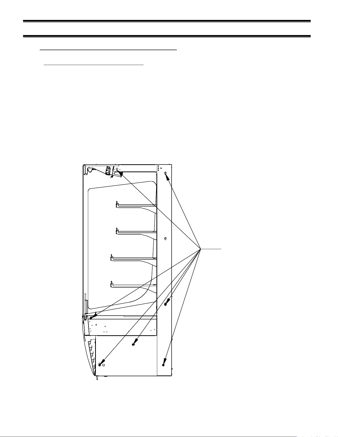
6.1.1 Join heated to heated (VHSS to VHSS)
1. Remove all Shelves, display deck, interior back panel(s), exterior back(s), front and
rear base panel, and ceiling.
2. Position the right or left most unit in the desired position for the lineup to start, and level
this case.
3. Push the 2
nd
case next to the 1
st
and line them up as closely as possible.
4. Adjust the leveling legs of the 2
nd
case until the units and joining holes align with each
other.
5. Using (7) holes noted below, bolt units together with the supplied hardware, and attach
joining trim to remove the gap between the decks in the joined units. Re-use the screws
in the uprights, as well as the self-drilling screws provided with the kit.
JOINING HOLES
E3981 VHSS 11
6. Replace all panels that were previously removed.
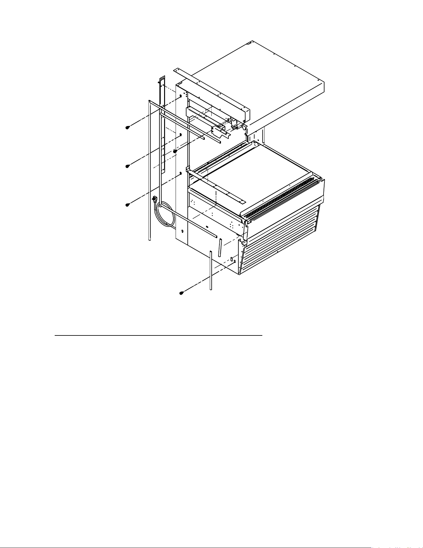
6.1.2 Join units with glass divider, or join heated to non-refrigerated
For this joining configuration, one unit will come with a lower end panel preinstalled with
glass. Five bolt holes will be exposed on the outside of this panel and are the locations that
will be used to join the units together. This kit also comes with top and rear exterior trim,
but no interior trim.
1. Remove all Shelves, display deck, interior back panel(s), exterior back(s), front and rear
base panel, and loosen honeycomb (see cleaning section for honeycomb removal)
material on the unfinished end to expose the holes used to bolt units together.
2. Position the right or left most unit in the desired position for the lineup to start, and level
this case.
3. Push the 2
nd
case next to the 1
st
and line them up as closely as possible.
4. Adjust the leveling legs of the 2
nd
case until the bolt holes align with the mating holes in the
joining case.
5. Push the units together so that the through bolts go through the case to be joined.
6. Using the hardware provided (1/4-20 screw, washer, lock washer), screw the 2
nd
case with
the unfinished end into the first case.
E3981 VHSS 12
A
DETAIL A
TOP JOIN TRIM
REAR JOIN TRIM
7. Finish the joining process loosening the glass trim on the case to slide the joining trim over
the existing trim and secure with the existing fasteners. Do this for both the top trim and
the rear trim.
FRONT VIEW
8. Replace any panels previously removed. Units are now joined.
E3981 VHSS 13
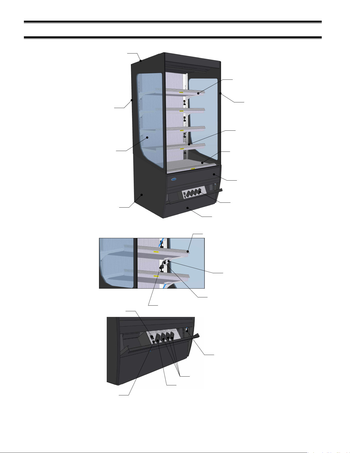
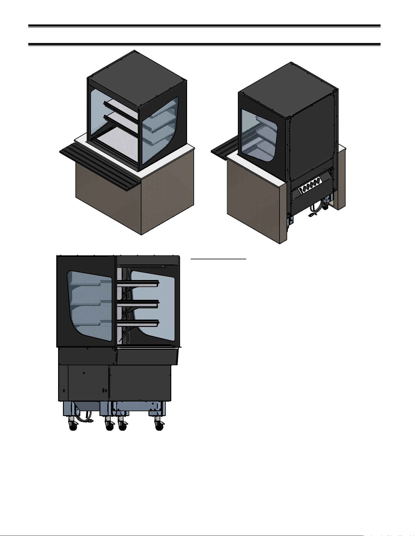
(7) FEATURE OVERVIEW
FLIP-DOWN
CONTROL PANEL
DISPLAY DECK
SHELF 1 (BTM)
SHELF 4 (TOP)
END PANEL
END GLASS
TOP GLASS TRIM
REAR GLASS TRIM
FRONT PANEL
CONTROL DOOR ASSEMBLY
GLASS TRIM
EXTRUSION
SHELF BRACKET
PRICE TAG MOLDING
HEATER CORD
HEATER RECEPTACLE
POWER SWITCH
LIGHT SWITCH
DECK HEATER
CONTROL
SHELF HEATER CONTROLS
DOOR MAGNET
E3981 VHSS 14
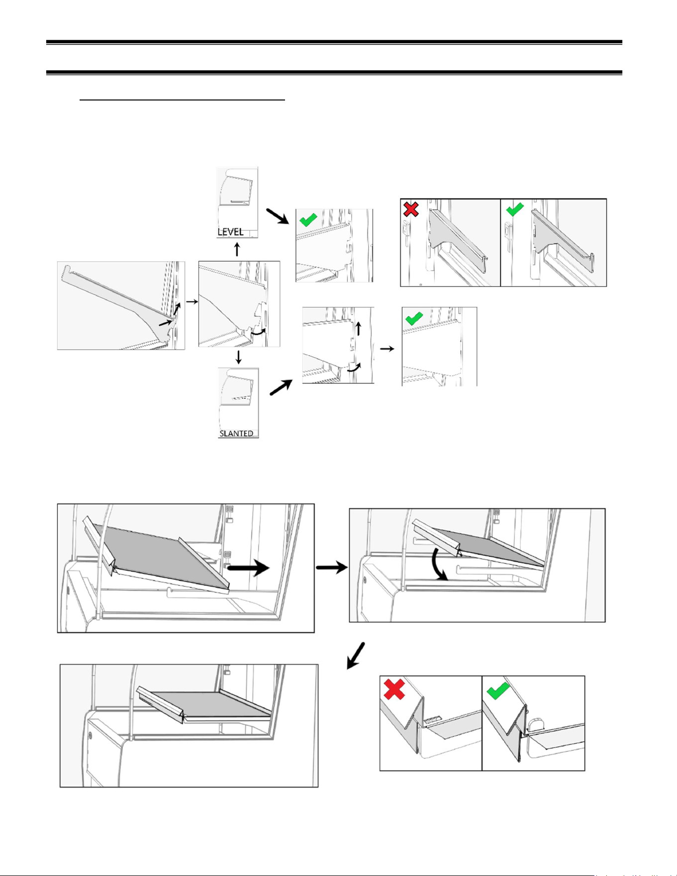
(8) SHELVING INSTALLATION AND REMOVAL
8.1 SHELF BRACKETS AND SUPPORTS
Follow the instructions shown in the diagram below to install shelf brackets. Follow the “LEVEL”
path if you want shelves to have no tilt or follow the “SLANTED” path if you want shelves with tilt.
Ensure brackets are well seated and face the proper direction.
Lay back of shelf across both brackets. Slide it to the rear and then lay the front of the shelf down.
Check that the retaining tab of the shelf brackets protrudes through the slot in the shelf.
E3981 VHSS 15
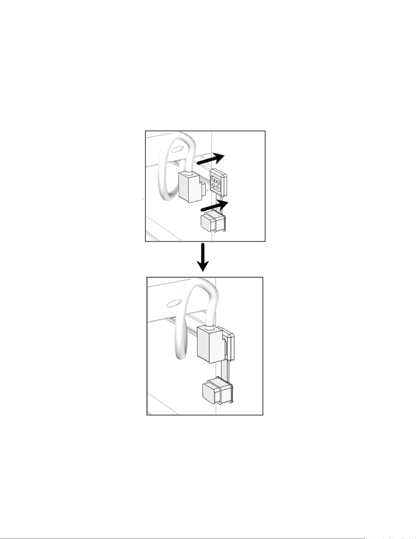
Make the heater connections from the back of the shelf into the receptacle of the vertical frame of
the unit. Remove the receptacle cap and push the heater cord (the heater cord comes out of the
left side of the shelf) into the nearest heater receptacle. The cord will only insert in one direction
as shown below.
Once power is applied to the display case you will be able to check if the cord connection has
been adequately made.
Tip: If the rear of the unit is accessible, it may be easier to remove the rear panel and make this
connection from the back of the case.
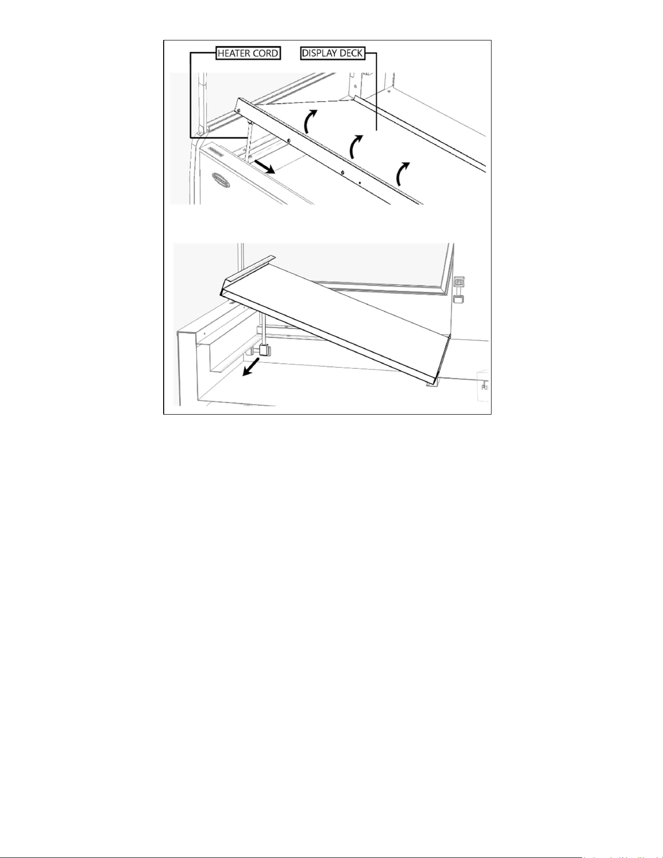
E3981 VHSS 16
To remove the deck simply lift on the front handle and rotate the front of the deck upward. Hold
the assembly in place and use your other hand to disengage the heater cord from the tub. Then
simply lift the deck from the unit. Installation is the reverse of removal.
E3981 VHSS 17
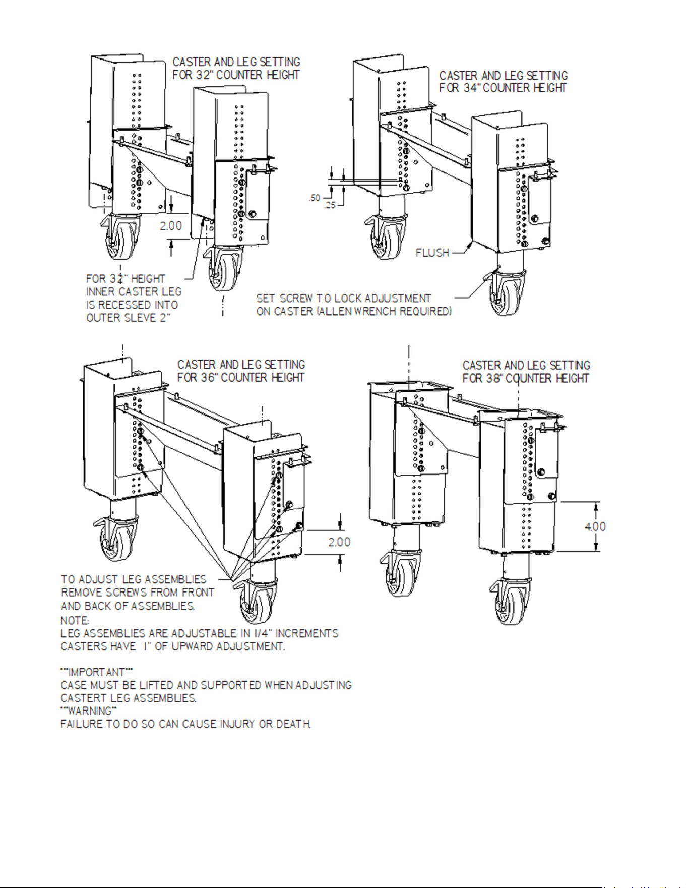
(9) SLIDE-IN LEG & CASTER ADJUSTMENTS
Slide In Models
Designed to slide/roll into a counter with an open
back.
Hot cases are available with rear mounted controls
only.
Case counter height is set at 34” from the factory.
Leg assemblies are adjustable in 1/4" increments.
Adjustable casters have 1” of upward adjustment to
fine tune height to match counter surfaces.
Casters are double locking in swivel and roll
directions.
The next page shows common counter height
adjustments.
***IMPORTANT***
CASE MUST BE LIFTED AND SECURED
TO ADJUST CASTER/LEG ASSEMBLIES.
***WARING***
FAILURE TO DO SO CAN CAUSE SEVERE
INJURY OR DEATH.
E3981 VHSS 18
NOTE: some leg adjustments can be done before the case is removed from the pallet
E3981 VHSS 19
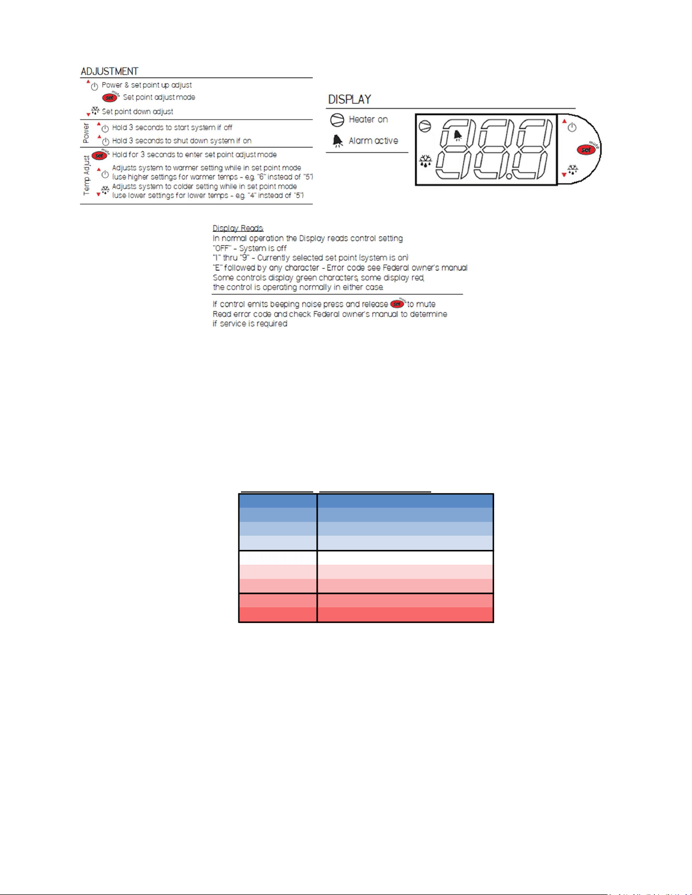
(10) CONTROL OPERATION
The controls are found behind the front panel pictured below. Pull forward on the short handle of
the flip down panel and gently rotate the panel down and let it rest on the toe kick. This exposes
the control panel. You now have access to the main power switch, light switch, and the heating
controls.
CONTROL PURPOSE
POWER ON/OFF
POWER ENTIRE UNIT OFF OR ON; TURNS
OFF ALL LIGHTS, HEATERS, AND
CONTROLS
LIGHTS ON/OFF TURN ALL LIGHTS ON OR OFF
TOP SHELF
CHANGE SHELF TEMPERATURE
SETPOINT AND TURN SHELF ON OR OFF
MIDDLE SHELF 2
MIDDLE SHELF 1
BOTTOM SHELF
DECK
NOTICE
Load items at 170°F or warmer. At time of loading, items stocked in unit MUST be pre-
heated at 170°F or warmer.
E3981 VHSS 20
Use the following procedure to adjust the control setpoints.
Error code E0=Temperature probe disconnected or failed.
The temperature controllers each reference one temperature probe that is mounted in the deck or
shelf depending on the control. Do not locate the probe to a different position.
Shelf temperature settings are digitally controlled via factory settings 1-9. Setting “1” provides the
coolest surface temperatures while setting “9” will provide the warmest.
Control Setting Food Reccomendations
Coolest 1 Cookies, Pastries, Non-perishables
2
3
4
5 Sandwiches
6
7
8 Rotisserie Chicken, Pizza, Fries
Warmest 9
E3981 VHSS 21
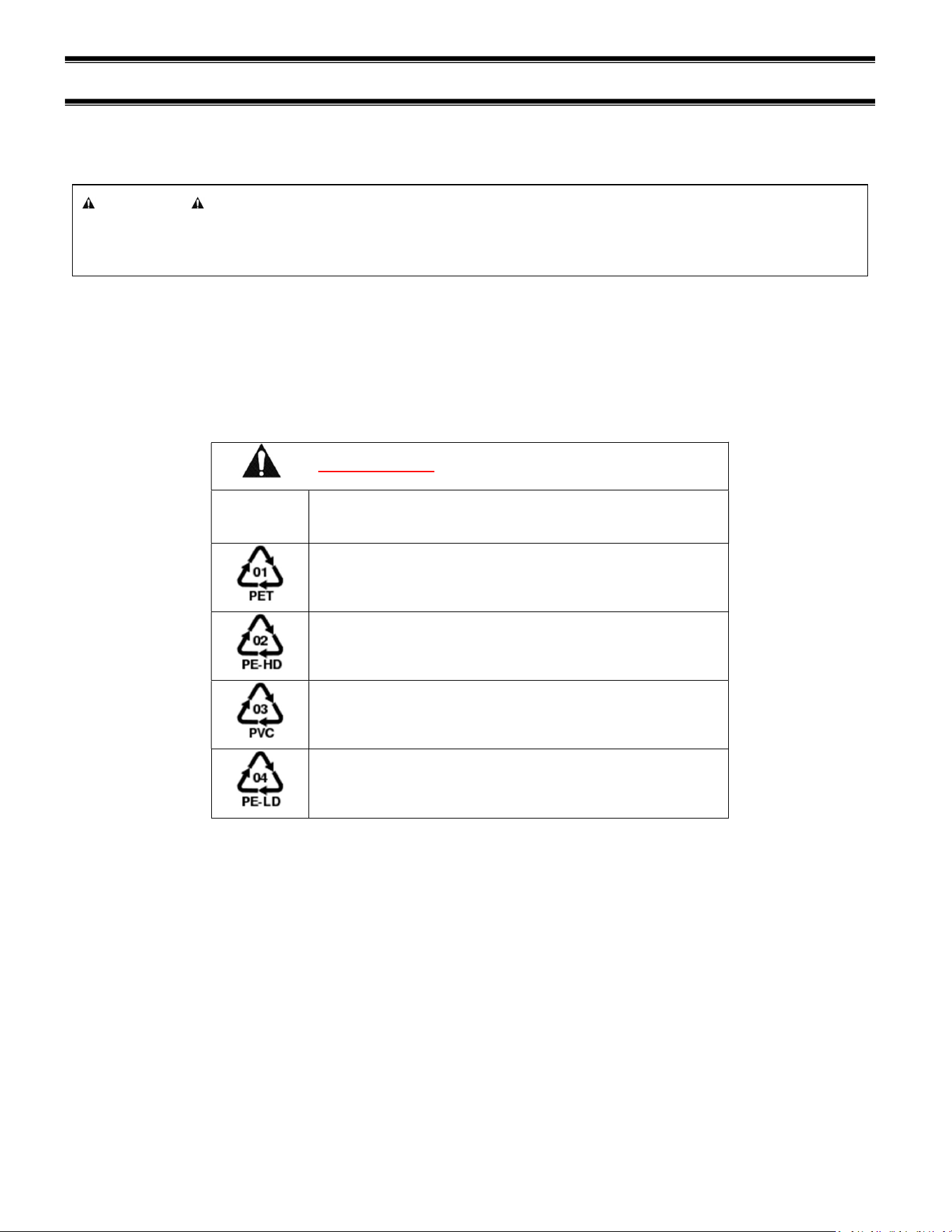
(11) FOOD PACKAGING RECOMMENDATIONS
This merchandiser is designed to be used with pre-packaged product only. All food items placed
in the merchandiser must be packaged. No foods should be placed in the merchandiser without
packaging.
Not all packaging is compatible with this merchandiser. Any packaging material with a rating of
less than 250°F should not be used.
Typically, polypropylene (recycle code 5) works well, but check with the manufacturer first to get
an accurate assessment of the application.
DO NOT USE the following packaging materials:
Recycle
Code Material Name
Polyethylene terephthalate
High-density polyethylene
Polyvinyl chloride
Low-density polyethylene
Materials listed in the table above will not survive the high temperature conditions of this
merchandiser.
NOTICE
Load items at 170°F or warmer. At time of loading, items stocked in unit MUST be pre-
heated at 170°F or warmer.
E3981 VHSS 22
(12) CLEANING INSTRUCTIONS
12.1 DAILY CLEANING
The case should be cleaned thoroughly, as described in the weekly cleaning section before it is
used for the first time.
NOTICE:
Avoid splashing or soaking any electrical components with water to prevent
electrical damage to the case.
NOTICE:
Shut off power switch and remove all product from case. Allow enough time
for the unit to reach room temperature before proceeding with cleaning.
NOTICE:
Remove all product from case before proceeding with cleaning procedure.
NOTICE:
This case is not designed to be cleaned by flushing.
Note: For major spills or foreign material buildup perform the weekly cleaning
instructions.
Note: Detergents are not recommended and do not use abrasive cleaners or pads to
prevent scratching of surfaces.
1. Clean all foreign materials from the door opening.
1. Wipe complete interior of both the upper & lower areas of case using a damp cloth.
2. The remaining exterior surface should be wiped down using any ammoniated cleaners or soapy
warm water.
12.2 WEEKLY CLEANING
This procedure is recommended on a weekly basis. It may need to be performed more often if
necessary, to maintain a clean, sanitary case. The case should be cleaned to this procedure before
using the first time.
NOTICE:
Avoid splashing or soaking any electrical components with water to prevent
electrical damage to the case.
E3981 VHSS 23
NOTICE:
Shut off power switches and remove all product from case. Allow enough
time for the unit to reach room temperature before proceeding with cleaning.
NOTICE:
Remove all product from case before proceeding with cleaning procedure.
NOTICE:
This case is not designed to be cleaned by flushing.
1. Side, and rear door glass can be cleaned with common window cleaners.
2. Remove interior shelving and display deck from unit as described in the “Shelving Installation and
Removal” section of this manual.
3. Clean all shelves, shelf supports, shelf light deflectors, shelf brackets, shelf standards using warm
soapy water and a brush. Rinse thoroughly and allow to dry.
4. Remove the display deck and clean using warm soapy water and a brush. Rinse thoroughly and
allow to dry.
5. Clean the entire interior of the case using warm soapy water. Wipe off all soapy water with a
damp cloth and allow to dry. (DO NOT use solvents such as Acetone, Benzene, Carbon
Tetrachloride, and Lacquer Thinners)
6. Reassemble all components in reverse order.
7. The exterior surfaces should be wiped down using any ammoniated cleansers or warm soapy
water.

E3981 VHSS 24
(13) SERVICE
Service Information
Before any service work is
performed on the case, make
sure all power is disconnected to
the case.
To find a service company in your area, please visit our website at
https://federalind.com/support-service/service-rep-locator. There you can also find self-
service tools to help you get the answers you need faster!
For warranty service requests and all technical support, including compressors and other
service parts please contact:
- Phone: (833) 238-8168
- Email: techservice@partstown.com
Federal Industries has partnered with Parts Town for ALL Non-Warranty Part Identification,
Pricing, Lead Times, Orders & Freight Quotes. Please contact Parts Town directly if you
need parts:
- Website: PartsTown.com
- Phone: 833-809-8188
WARNING
RISK OF ELECTRIC
SHOCK
DISCONNECT POWER
BEFORE SERVICING UNIT

E3981 VHSS 25
(14) SALE & DISPOSAL
14.1 OWNER RESPONSIBILITY
If you sell or give away your Federal Industries case you must make sure that all safety labels
and the Installation-Service Manual are included with it. If you need replacement labels or
manuals, Federal Industries will provide them free of charge. Contact the customer service
department at Federal Industries at (800) 356-4206.
The customer service department at Federal Industries should be contacted at the time of sale or
disposal of your case so records may be kept of its new location.

E3981 VHSS 26
(15) TROUBLESHOOTING
Pre-Service Checklist
You may avoid the cost and inconvenience of an unnecessary service call by first
reviewing this checklist of frequently encountered situations that can cause unsatisfactory
case performance.
Case Does Not Operate
Check for disconnected power supply.
Check for tripped breaker on blown fuse.
Check that the thermostat display is on and is not displaying an error.
Lights Do Not Operate
Check that light switch is on.
Check for tripped breaker or blown fuse.
Check that light cords are plugged in correctly to sockets. Check connector on LED
light, and connector on
Temperature is too low
Increase control setpoint
Check supply voltage to case is above 208V
Look for HVAC discharge vents, fans, and other possible air disruptions.
If using rack, check rack orientation. Flip rack over if needed so product is closer to
the shelf surface.
Temperature is too high
Turn down control setpoint
Check the control for errors and contact service
Use supplied food rack to reduce heat intensity on food
Control Error
Turn the main power switch to off to power down the unit
Wait 10s, and power the unit back on
If error is still present, ensure all heater cords are seated fully into their receptacles.
E3981 VHSS 27
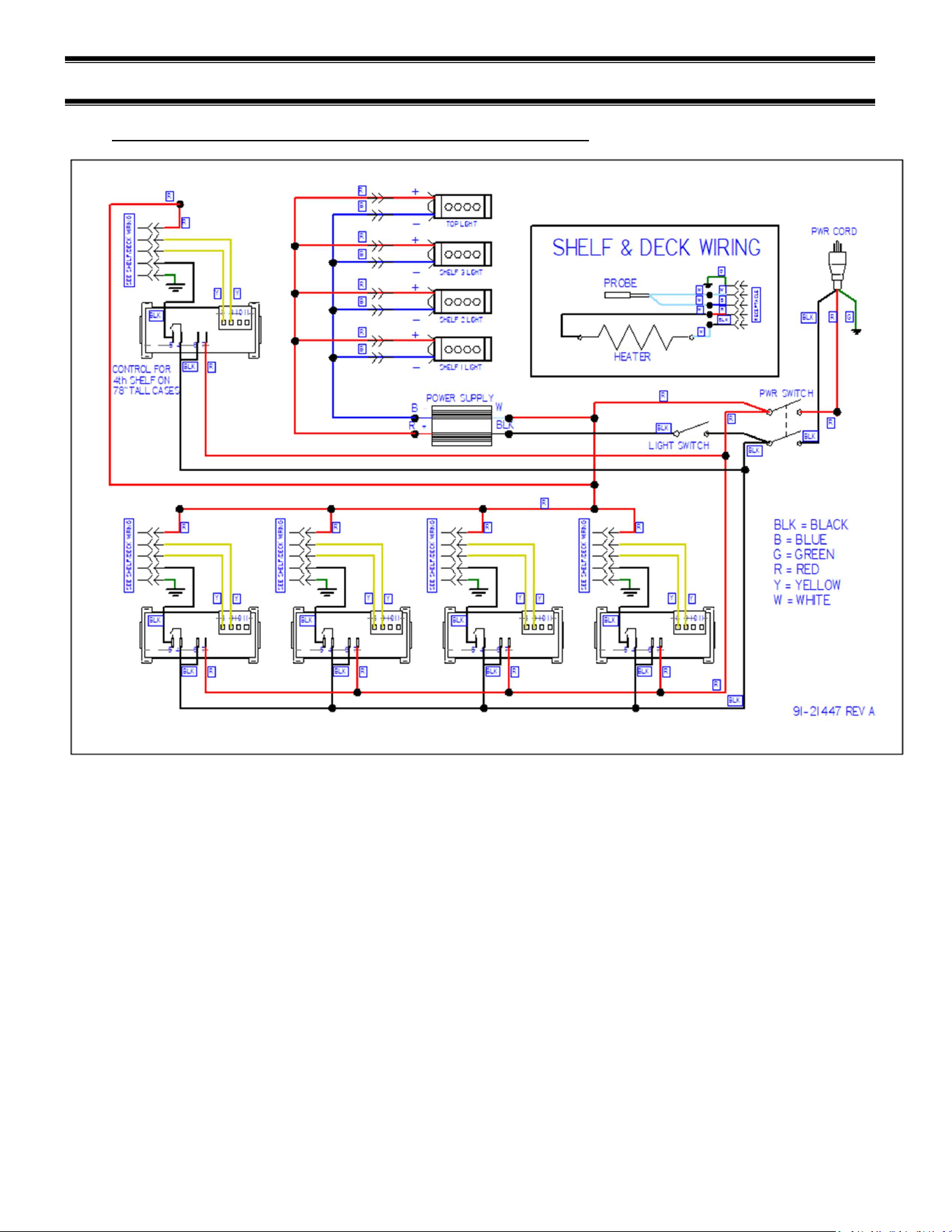
(16) WIRING DIAGRAMS
16.1 VHSS2460, VHSS3660, VHSS4860, VHSS2478, VHSS3678
E3981 VHSS 28
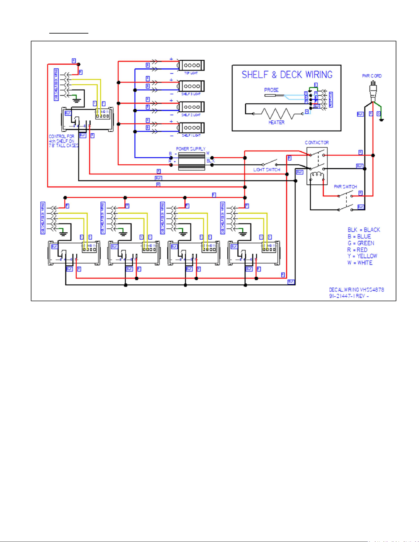
16.2 VHSS4878
E3981 VHSS 29
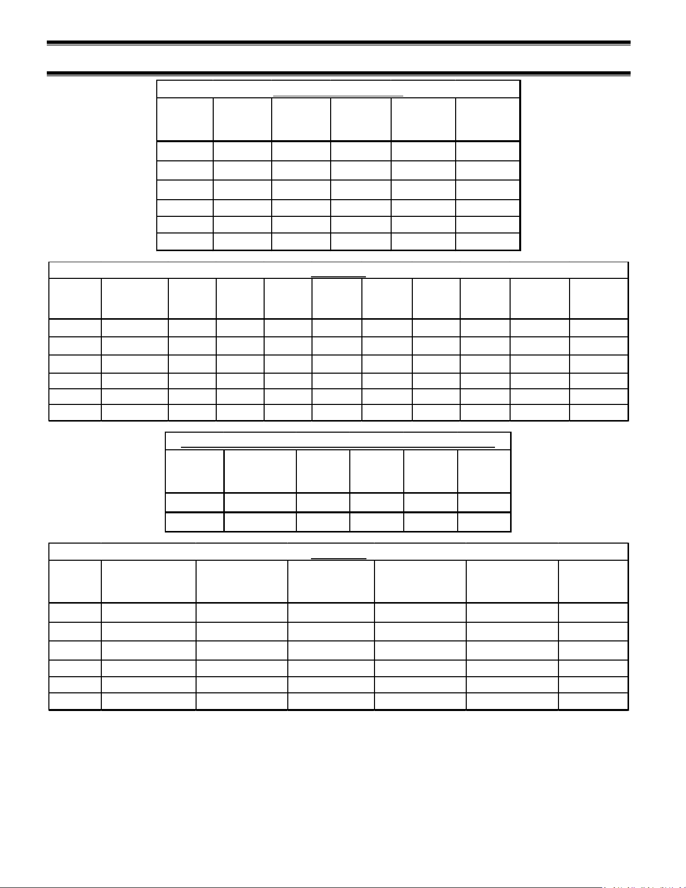
(17) VHSS SERVICE PARTS
Model Shelf Part# Deck Part#
LEFT SHELF
BRACKET
RIGHT SHELF
BRACKET
CAUTION
HOT STICKER
VHSS2460 SA6035-S SA6041-S 67-21204-L 67-21204-R 91-10207
VHSS3660 SA6035-1S SA6041-1S 67-21204-L 67-21204-R 91-10207
VHSS4860 SA6035-2S SA6041-2S 67-21204-L 67-21204-R 91-10207
VHSS2478
SA6035-S
SA6041-S
67-21204-L
67-21204-R
91-10207
VHSS3678
SA6035-1S
SA6041-1S
67-21204-L
67-21204-R
91-10207
VHSS4878 SA6035-2S SA6041-2S 67-21204-L 67-21204-R 91-10207
Heated Shelves and Deck
Model
TEMPERATURE
CONTROLS
POWER
SWITCH
LIGHT
SWITCH
LED
POWER
SUPPLY
POWER
CORD
WIRE
HARNESS,
CONTROL
WIRE
HARNESS,
HEATER
HARNESS,
LIGHTS
RECEPTACLE,
HEATER
RELAY,DPST-
NO 30AMP
240V
VHSS2460 32-19865-16 41-18186 41-11066 39-20986 43-17839 43-21534 43-21098 43-21009 43-21100 -
VHSS3660 32-19865-16 41-18186 41-11066 39-20986 43-17839 43-21534 43-21098 43-21009 43-21100 -
VHSS4860 32-19865-16 41-18186 41-11066 39-20986 43-19090 43-21534 43-21098 43-21009 43-21100 -
VHSS2478
32-19865-16
41-18186
41-11066
39-20986
43-17839
43-21534
43-21098
43-21009
43-21100
-
VHSS3678
32-19865-16
41-18186
41-11066
39-20986
43-19090
43-21534
43-21098
43-21009
43-21100
-
VHSS4878 32-19865-16 41-18186 41-11066 39-20986 43-20234 43-21534 43-21098 43-21009 43-21100 41-21577
ELECTRICAL
Model
INSTRUCTION
DECAL
DOOR
MAGNET
HINGE
RIVET
HINGE
BUSHING
PLASTIC
RIVET
VHSS 91-21417 56-17636 77-12280 81-21489 77-21488
VHSS-SLD
91-21417
--- --- --- ---
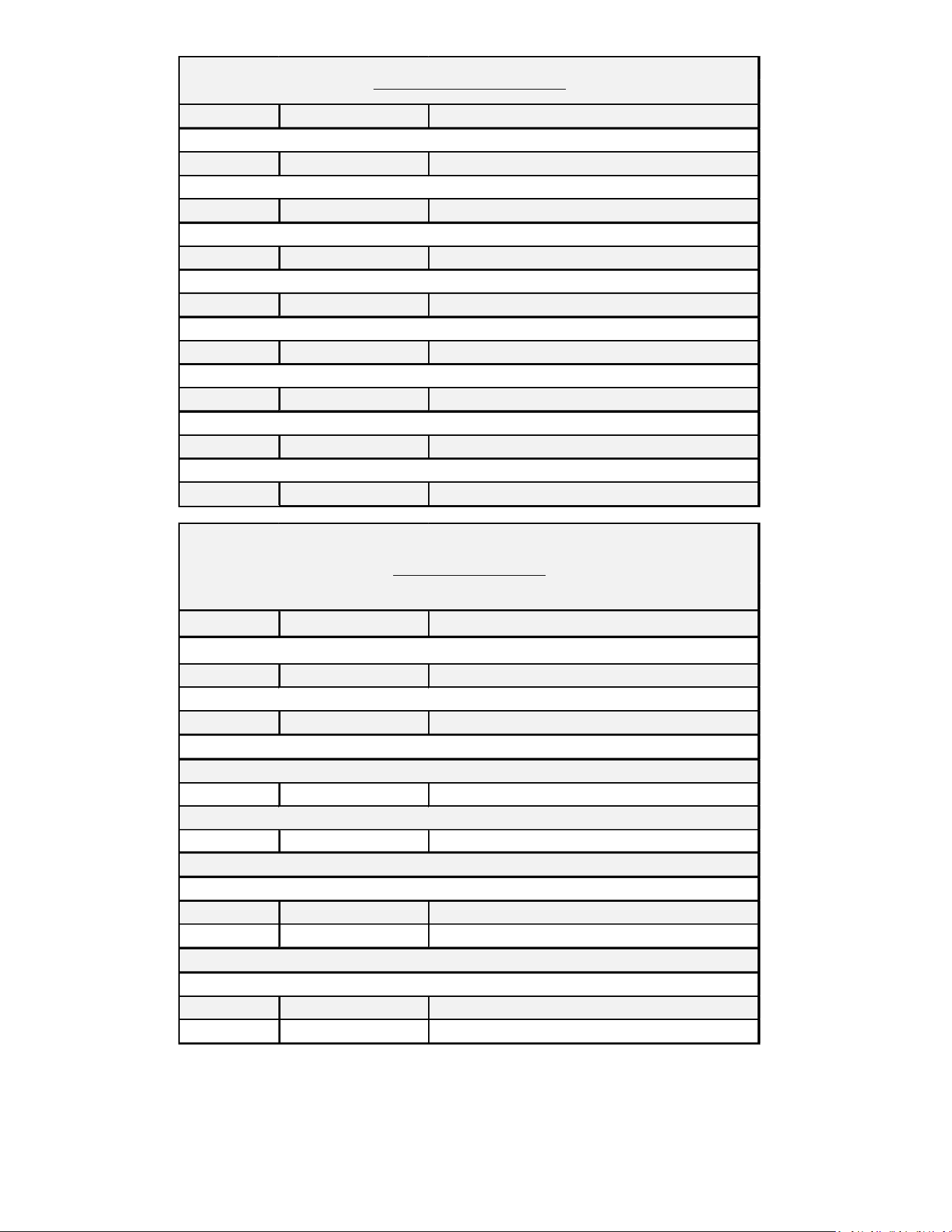
CONTROL PANEL ASSEMBLY (SEE ELECTRICAL FOR CONTROLS)
Model
TOP LIGHT SHELF LIGHT
LED LIGHT CORDS,
SHELF
LED LIGHT CORDS,
TOP LIGHT
LED MOUNTING
CLIP
SHELF LIGHT
CORD CLIP
VHSS2460 42-20871-20C35 42-20871-18C35 43-21333 43-20862-1B 67-20869-30 67-20952
VHSS3660 42-20871-30C35 42-20871-25C35 43-21333 43-20862-1B 67-20869-30 67-20952
VHSS4860 42-20871-42C35 42-20871-38C35 43-21333 43-20862-1B 67-20869-30 67-20952
VHSS2478
42-20871-20C35
42-20871-18C35
43-21333
43-20862-1B
67-20869-30
67-20952
VHSS3678
42-20871-30C35
42-20871-25C35
43-21333
43-20862-1B
67-20869-30
67-20952
VHSS4878 42-20871-42C35 42-20871-38C35 43-21333 43-20862-1B 67-20869-30 67-20952
LED LIGHTS
E3981 VHSS 30
LEFT RIGHT
BLACK 50-21330-2B 50-21330-2B
BLACK 50-21330-12LB 50-21330-12RB
BLACK 50-21330-1B 50-21330-1B
BLACK 50-21330-11LB 50-21330-11RB
BLACK 50-21299-2B 50-21299-2B
BLACK 50-21299-12LB 50-21299-12RB
BLACK 50-21299-1B 50-21299-1B
BLACK 50-21619-11LB 50-21619-11RB
END GLASS PANELS CURVED CLEAR 60" TALL
END GLASS PANELS CURVED REFLECTIVE 60" TALL
END GLASS PANELS CURVED CLEAR 78" TALL
END GLASS PANELS CURVED REFLECTIVE 78" TALL
GLASS END PANELS VISION
END GLASS PANELS SQUARE CLEAR 60" TALL
END GLASS PANELS SQUARE REFLECTIVE 60" TALL
END GLASS PANELS SQUARE CLEAR 78" TALL
END GLASS PANELS SQUARE REFLECTIVE 78" TALL
LEFT RIGHT
BLACK 50-21605-2B 50-21605-2B
50-21605-12LB 50-21605-12RB
BLACK 50-21619-2B 50-21619-2B
50-21619-12LB 50-21619-12RB
BLACK 68-21623-23L 68-21623-23R
WHITE 68-21623-26L 68-21623-26R
BLACK 68-21622-23L 68-21622-23R
WHITE 68-21622-26L 68-21622-26R
END PANELS SLIDE-IN
END GLASS PANELS SQUARE CLEAR
END GLASS PANELS SQUARE REFLECTIVE
END GLASS PANELS CURVED CLEAR
END GLASS PANELS CURVED REFLECTIVE
END PANELS FOR SOLID END STRAIGHT PROFILE LAMINATED, 60IN HEIGHT
END PANELS FOR SOLID END CURVED PROFILE LAMINATED, 60IN HEIGHT

E3981 VHSS 31
LEGS AND CASTERS
Description PART# QTY/CASE
LEG LEVELER ASSEMBLY SA4368-1 4
LEG LEVELER 65-21273 4
HOUSING SA4295 4
6" LEG ASSEMBLY SA4368-2 4
6" LEG 65-12886 4
SCREW, 1/4-20 75-10948 16
HOUSING SA4295 4
4" CASTER ASSEMBLY SA4368-3 4
4" CASTER 65-10675 4
SCREW, 1/4-20 75-10948 16
HOUSING SA4295 4
2.5" CASTER ASSEMBLY SA4368-20 4
2.5" CASTER 65-15185 4
SCREW, 1/4-20 75-10948 16
HOUSING SA4295 4
RECESSED CASTER ASSEMBLY SA4368-4 4
2.5" CASTER 65-17352 4
SCREW, 1/4-20 75-10948 16
HOUSING M15895-2 4
6" SEISMIC LEG ASSEMBLY SA4368-13 4
6" SEISMIC LEG 65-19069 4
SCREW, 1/4-20 75-10948 16
HOUSING SA4295 4
4
ADJUSTABLE CASTERS SLIDE-IN 65-21657 4
SCREW, 1/4-20 75-10948 64
INNER SLIDE HOUSING M21799 4
OUTER SLIDE HOUSING M21798 4
BRACE SLIDE HOUSING M21814 2
SLIDE -IN ADJUSTABLE CASTER ASSEMBLIES
E3981 VHSS 32
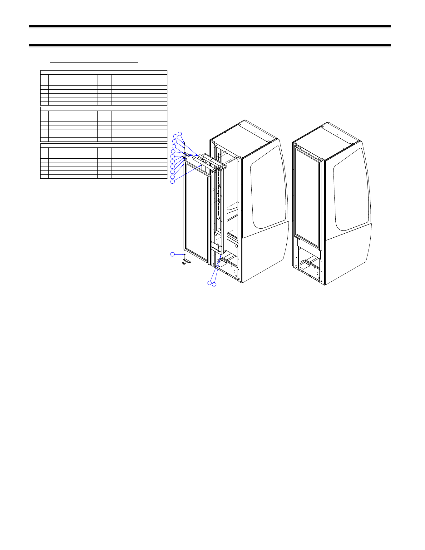
(18) OPTIONS
18.1 REAR SWINGING DOOR
9
10
11
12
14
13
1
2
3
4
5
7
8
6
828/829-9640-INTB BLACK INTERIOR PARTS REAR SWING DOOR VHSS/VNSS2460/2478
ITEM PART #
828-9640
VHSS2460
QTY
828-9640
VHSS2460
PART #
829-9640
VHSS2478
QTY
829-9640
VHSS2478
BILL
DESIG.
COLOR
DESIG.
DESCRIPTION
4 75-11483 12 75-11483 12 INT B SCREW,8-18X.5,PH TR,TEK2,410SS
11 M21576-11LB 1 M21576-1LB 1 INT B LINER,DOOR SIDE
12 M21576-11RB 1 M21576-1RB 1 INT B LINER,DOOR SIDE
13 M21577-5B 1 M21577-5B 1 INT B LINER,DOOR TOP
14 M21577-B 1 M21577-B 1 INT B LINER,DOOR BOTTOM
828/829-9640-INTW WHITE NTERIOR PARTS REAR SWING DOOR VHSS/VNSS2460/2478
ITEM PART #
828-9640
VHSS2460
QTY
828-9640
VHSS2460
PART #
829-9640
VHSS2478
QTY
829-9640
VHSS2478
BILL
DESIG.
COLOR
DESIG.
DESCRIPTION
4 75-11483 12 75-11483 12 INT W SCREW,8-18X.5,PH TR,TEK2,410SS
11 M21576-11LW 1 M21576-1LW 1 INT W LINER,DOOR SIDE
12 M21576-11RW 1 M21576-1RW 1 INT W LINER,DOOR SIDE
13 M21577-5W 1 M21577-5W 1 INT W LINER,DOOR TOP
14 M21577-W 1 M21577-W 1 INT W LINER,DOOR BOTTOM
828/829-9640-INTS S/S INTERIOR PARTS REAR SWING DOOR VHSS/VNSS2460/2478
ITEM PART #
828-9640
VHSS2460
QTY
828-9640
VHSS2460
PART #
829-9640
VHSS2478
QTY
829-9640
VHSS2478
BILL
DESIG.
COLOR
DESIG.
DESCRIPTION
4 75-11483 12 75-11483 12 INT S SCREW,8-18X.5,PH TR,TEK2,410SS
11 M21576-11LS 1 M21576-1LS 1 INT S LINER,DOOR SIDE
12 M21576-11RS 1 M21576-1RS 1 INT S LINER,DOOR SIDE
13 M21577-5S 1 M21577-5S 1 INT S LINER,DOOR TOP
14 M21577-S 1 M21577-S 1 INT S LINER,DOOR BOTTOM
E3981 VHSS 33
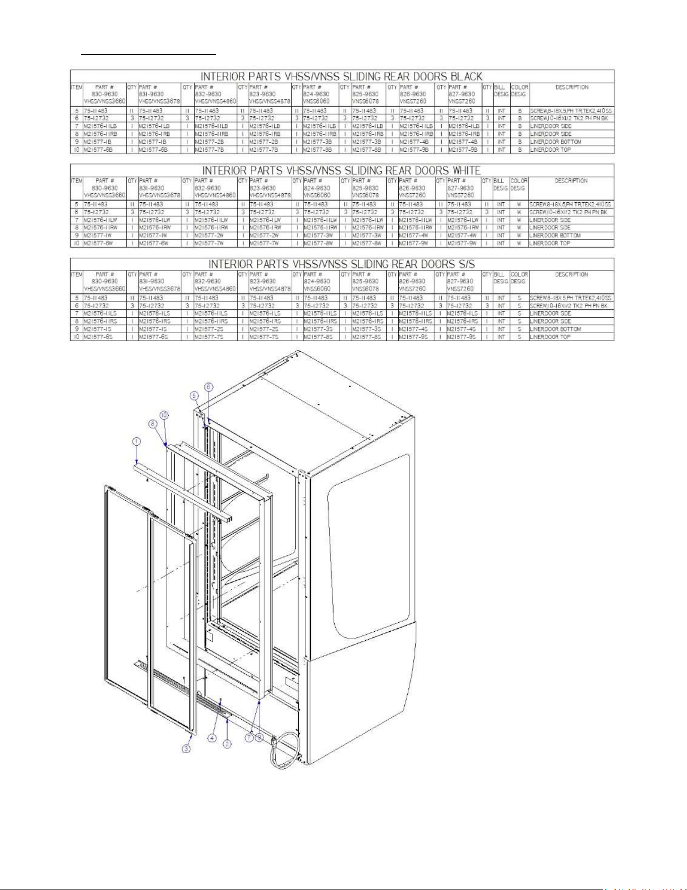
18.2 REAR SLIDING DOORS

E3981 VHSS 34
REV
CHANGE RECORD
APP’D DATE ECN#
- INITIAL RELEASE JTR 11/16/21 -
A Added quick start guide, and made corrections JTR 12/8/21 -
B Separated quick start guide JTR 12/21/21 3763
C Added VHSS4878 case info & updated 91-21447 diagram to Rev A ADC 7/13/2022 3778
D Added EO error code, wire harness control 43-21534 was 43-21093 SES 10/4/22 3813
E Added slide-in BJW 8/8/23 3870
F Updated Joining Kit BJW 02/02/24 3898
California Residents Only.
WARNING
This product can expose you to chemicals including chromium which is known to the State of California to
cause cancer and birth defects or other reproductive harm. For more information go to
www.P65Warnings.ca.gov