E3980-20
Rev 0 1/30/25
Engineering and technical data are subject to change without notice.
FEDERAL INDUSTRIES 215 Federal Ave Belleville, WI 53508
INSTALLATION & OPERATIONS INSTRUCTIONS
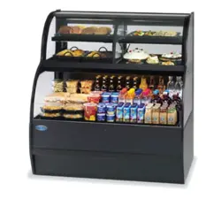
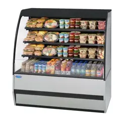
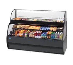
VRSS, VRSL, & VRSSL-MLK: Self-Contained & Remote Refrigerated
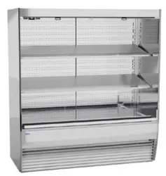
VNSS: Non-Refrigerated Displays

E3980 VISION R290
2
TABLE OF CONTENTS
Table of Contents .................................................................................................................................. 2
(1) Introduction ................................................................................................................................ 3
1.1 Serial Number ......................................................................................................................... 3
(2) Warning Labels & Safety Instructions......................................................................................... 4
(3) REFRIGERATION WARNING INSTALLATION-REPAIR-DECOMMISSIONING ................... 5
(4) Feature Identification ................................................................................................................ 11
(5) Base Component LayoutS ....................................................................................................... 13
(6) Panel Removal ......................................................................................................................... 18
6.1 VRSS & VRSL Models .......................................................................................................... 18
6.2 VRSL-MLK ModelsL ............................................................................................................. 19
(7) Prior to Unpacking Equipment .................................................................................................. 20
(8) Installation instructions ............................................................................................................. 21
8.1 Locating The Display Case ................................................................................................... 21
8.2 Removing Case From Shipping Skid .................................................................................... 22
8.3 Single Case Installation (Stand alone units) ......................................................................... 24
8.4 Installation for joined cases (Lineups) ................................................................................... 24
8.5 installation in an alcove ......................................................................................................... 27
(9) Shelf installation and removal .................................................................................................. 28
(10) Security Night Cover (Optional) ................................................................................................ 31
(11) Slide-In Models -Leg & Caster Adjustments ............................................................................. 32
(12) Electronic Temperature Control (Refrigerated units only) ........................................................ 35
(13) Initial Startup (Refrigerated units only) ..................................................................................... 38
(14) Cleaning Instructions ................................................................................................................ 40
14.1 Daily Cleaning ...................................................................................................................... 40
14.2 Weekly Cleaning ................................................................................................................... 40
14.3 Cleaning Condenser Coil ...................................................................................................... 42
(15) Service ..................................................................................................................................... 43
(16) SALE & Decommissioning ....................................................................................................... 44
(17) Electrical and refrigeration specs ............................................................................................. 45
(18) Wiring Diagram ........................................................................................................................ 47
18.1 VRSS Self Contained R290 .................................................................................................. 47
18.2 VRSS Remote ...................................................................................................................... 48
18.3 VNSS .................................................................................................................................... 48
18.4 VRSL-MLK ............................................................................................................................ 49
E3980 VISION R290
3
(19) Service Parts ............................................................................................................................ 50
Introduction
Thank you for purchasing a Federal Industries display case. This manual contains important
instructions for installing and servicing your new display case. A repair parts list and wiring diagram
are also included in the manual. Read all these documents carefully before installing or servicing your
case.
NOTICE
Read this manual before installing your case. Keep this manual and
refer to it before doing any service on the equipment. Failure to do so
could result in personal injury or damage to the case.
NOTICE
Installation and service of the electrical components in the case must
be performed by a licensed electrician.
The portions of this manual covering components contain technical
instructions intended only for persons qualified to perform electrical
work.
DANGER
Improper or faulty hookup of electrical components in the case can
result in severe injury or death.
All electrical wiring hookups must be done in accordance with all
applicable local, regional, or national standards.
1.1 SERIAL NUMBER
Record the model and serial numbers of the case for easy reference. Always refer to both model and serial
numbers in your correspondence with Federal regarding the case.
Case Model__________________________ Serial Number______________________
This manual cannot cover every installation, use, or service situation. If you need additional information, call or
write us:
WARRANTY/TECHNICAL SERVICE DEPARTMENT
Parts Town
1200 Greenbriar Dr.
Addison, IL 60101
Toll Free: (833) 238-8168
Email: [email protected]
E3980 VISION R290
4
(2) WARNING LABELS & SAFETY INSTRUCTIONS
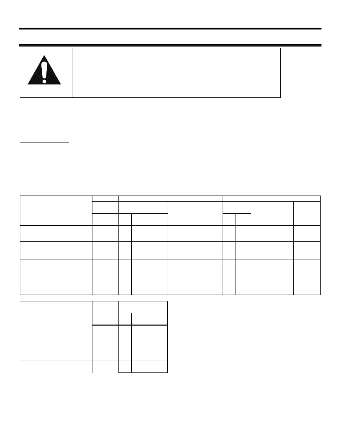
This is the safety-alert symbol. When you see this symbol on your
case or in the manual, be alert to the potential for personal injury or
damage to your equipment.
Be sure you understand all the safety messages and always follow recommended precautions and
safe operating procedures.
NOTICE TO EMPLOYERS:
You must make sure that everyone who installs, uses, or services
your case is thoroughly familiar with all safety information and
procedures.
Important safety information is presented in this section and throughout the manual. The following
signal words are used in the warning and safety messages:
DANGER: Severe injury or death will occur if you ignore the message.
WARNING: Severe injury or death can occur if you ignore the message.
CAUTION: Minor injury or damage to your case can occur if you ignore the message.
NOTICE:
This is important installation, operation, or service information. If you ignore
the message, you may damage your case.
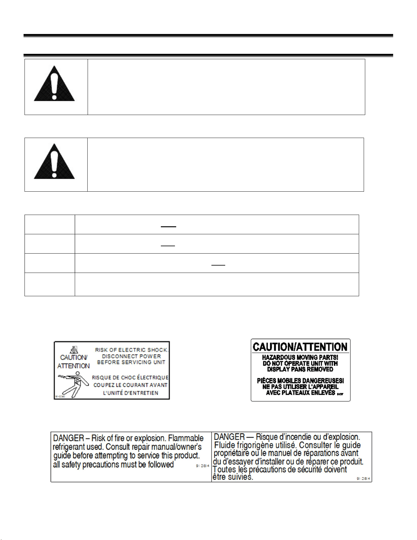
The warning and safety labels shown throughout this manual are placed on your Federal
Industries case at the factory. Follow all warning label instructions. If any warning or safety labels
become lost or damaged, call our customer service department at (800) 356-4206 for
replacements.
This label is located behind the removable base This label is located under display
deck panels display and under deck pans.
This label is located by condensing unit
E3980 VISION R290
5
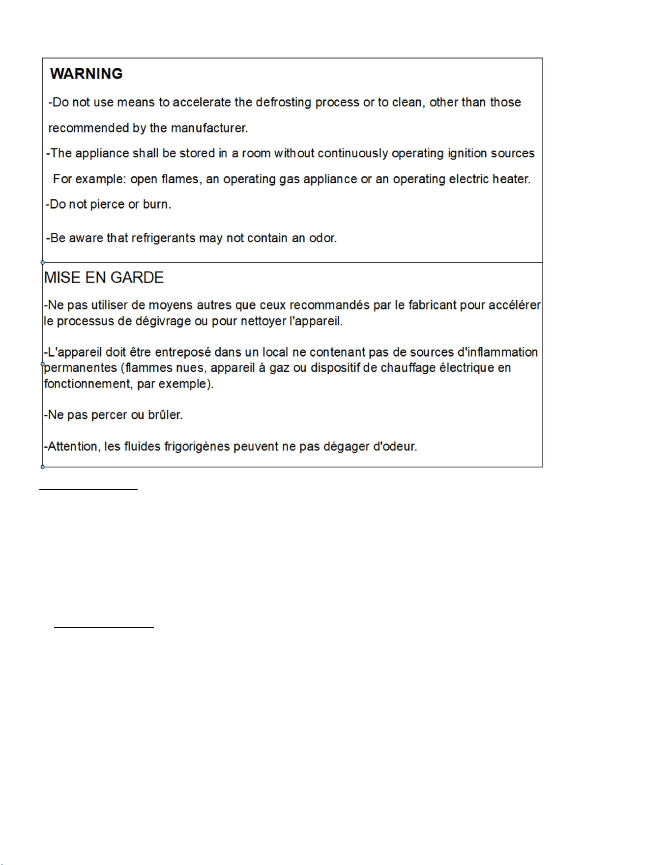
(3) REFRIGERATION WARNING
INSTALLATION-REPAIR-DECOMMISSIONING
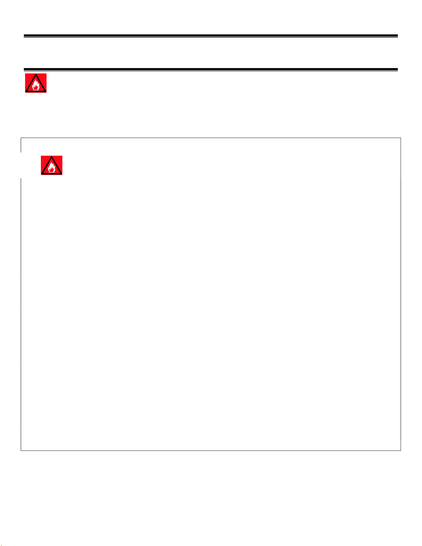
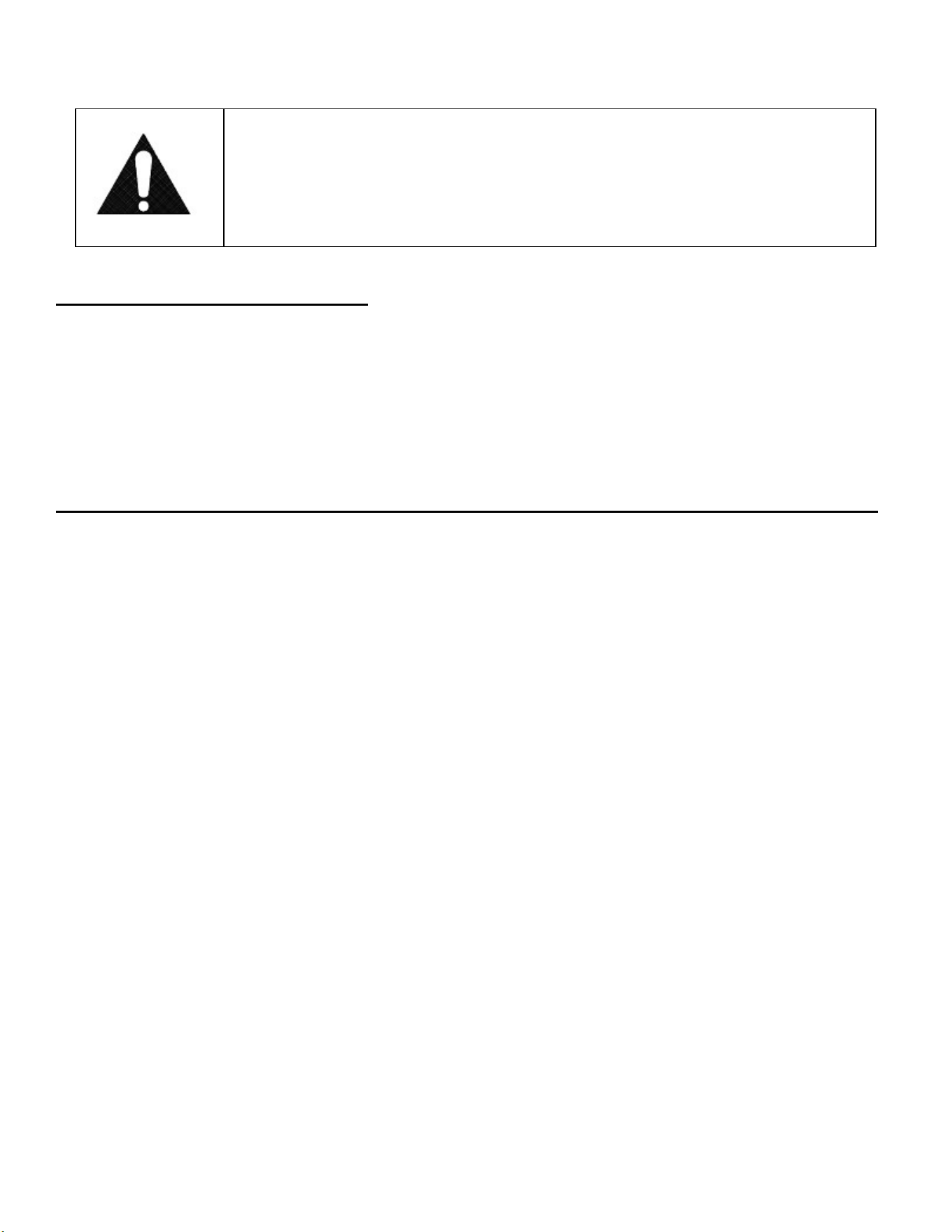
This is the Danger-Flammable symbol. When you see this symbol on your case or in the manual, be alert
to the potential for risk of fire or explosion.
Be sure you understand all the safety messages and always follow recommended precautions and
safe operating procedures.
DANGER
Risk of fire or explosion. Flammable refrigerant used. To be repaired only by trained service personnel.
Do not puncture refrigerant tubing. Dispose of properly in accordance with federal or local regulations
Consult repair manual/owner’s guide before attempting to service this product. All safety precautions
must be followed.
Follow handling instructions carefully in compliance with national regulations.
Auxiliary devices which may be ignition sources shall not be installed in the ductwork, other than
auxiliary devices listed for use with the specific appliance.
Do not store explosive substances (such as aerosol cans with a flammable propellant) in this case.
Do not use an electrical appliance INSIDE the food storage compartments unless its type is
recommended by manufacturer.
Flammable refrigerant type specified on case nameplate is on the serial label.
APPLIES TO R290 REFRIGERANT MODELS ONLY! Contains a charge of R290 refrigerant with a lower
flammability limit (LFL) of .038kg/m³. See table for amount of charge.
E3980 VISION R290
6
3. Qualification: All refrigeration and electrical maintenance, service, and repair must be performed
by a Certified Technician that is trained in the required flammable refrigerants safety procedures.
Technicians must read the entire section “REFRIGERATION WARNINGS SECTION” of this manual.
Including but not limited to the following:
a) breaking into the refrigerating circuit.
b) opening of sealed components.
c) opening of ventilated enclosures.
4.Checks to Area: Prior to beginning work on systems containing FLAMMABLE REFRIGERANTS,
safety checks are necessary to ensure that the risk of ignition is minimized prior to conducting work
on the system.
-Capacitors are discharged: this shall be done in a safe manner to avoid the possibility of sparkling.
- No live electrical components and wiring are exposed while charging, recovering or purging the
system.
- Continuity of earth bonding.
-Work shall be undertaken under a controlled procedure to minimize the risk of a
flammable gas or vapor being present while the work is being performed.

E3980 VISION R290
7
-All maintenance staff and others working in the local area should be instructed on the nature of the
work being carried out. Work in confined spaces shall be avoided.
-The area shall be checked with an appropriate refrigerant detector prior to and during
work, to ensure the technician is aware of potentially toxic or flammable atmospheres.
Ensure that the leak detection equipment being used is suitable for use with all applicable
refrigerants, i.e., non-sparking, adequately sealed, or intrinsically safe.
-If any hot work is to be conducted on the refrigerating equipment or any associated parts,
appropriate fire extinguishing equipment shall be available on hand. A dry chemical or CO2 fire
extinguisher should be adjacent to the charging area.
-No person carrying out work in relation to a REFRIGERATING SYSTEM which involves exposing
any pipe work shall use any sources of ignition in such a manner that it may lead to the risk of fire or
explosion. All possible ignition sources, including cigarette smoking, should be kept sufficiently far
away from the site of installation, repairing, removing and disposal, during which refrigerant can
possibly be released to the surrounding space. Prior to work taking place, the area around the
equipment shall be surveyed to make sure that there are no flammable hazards or ignition risks. “No
Smoking” signs shall be displayed.
-Ensure that the area is in the open or that it is adequately ventilated before breaking into the system
or conducting any hot work. A degree of ventilation shall continue during the period that the work is
carried out. The ventilation should safely disperse any released refrigerant and preferably expel it
externally into the atmosphere.
-Where electrical components are being changed, they shall be fit for the purpose and to the correct
specification so as to minimize the risk of possible ignition due to incorrect parts. At all times, the
manufacturer’s maintenance and service guidelines shall be followed. If in doubt, consult the
manufacturer’s technical department for assistance. The following checks shall be applied to
installations using flammable refrigerants:
a) the actual REFRIGERANT CHARGE is in accordance with the room size within which the
refrigerant containing parts are installed.
b) The ventilation machinery and outlets are operating adequately and are not obstructed.
c) Markings of the equipment continue to be visible and legible. Markings and signs
that are illegible shall be corrected.
d) Refrigerating pipes or components are installed in a position where they are
unlikely to be exposed to any substance which may corrode refrigerant containing
-Repair and maintenance to electrical components shall include initial safety checks and
component inspection procedures. If a fault exists that could compromise safety, then no electrical
supply shall be connected to the circuit until it is satisfactorily dealt with. If the fault cannot be
corrected immediately but it is necessary to continue operation, an
An adequate temporary solution should be used. This shall be reported to the owner of the Initial
safety checks shall include:
5. Repairs to sealed components
-During repairs to sealed components, all electrical supplies shall be

E3980 VISION R290
8
disconnected from the equipment being worked upon prior to any removal of sealed
covers, etc. If it is necessary to have an electrical supply to equipment during
servicing, then a permanently operating form of leak detection shall be located at the most critical
point to warn of a potentially hazardous situation.
-Particular attention shall be paid to the following to ensure that by working on
electrical components, the casing is not altered in such a way that the level of protection is affected.
This shall include damage to cables, excessive number of connections, terminals not made to original
specification, damage to seals, incorrect fitting of glands, etc. Ensure that the apparatus is mounted
securely.
Ensure that seals or sealing materials have not degraded to the point that they no longer serve the
purpose of preventing the egress of flammable atmospheres. Replacement parts shall be in
accordance with the manufacturer’s specifications.
-Do not apply any permanent inductive or capacitance loads to the circuit without ensuring that this
will not exceed the permissible voltage and current permitted for the equipment in use.
NOTE The use of silicon sealants can inhibit the effectiveness of some types of leak detection
equipment. Intrinsically safe components do not have to be isolated prior to working on them.
8. Detection of flammable refrigerants: Under no circumstances shall potential ignition sources be
used in the searching for or detection of refrigerant leaks. A halide torch (or any other detector using
a naked flame) shall not be used.
The following leak detection methods are deemed acceptable for all refrigerant systems:
-Electronic leak detectors may be used to detect refrigerant leaks but, in the case of
FLAMMABLE REFRIGERANTS, the sensitivity might not be adequate or might need recalibration.
(Detection equipment shall be calibrated in a refrigerant-free area.) Ensure that the detector is not a
potential source of ignition and is suitable for the refrigerant used. Leak detection equipment shall be
set at a percentage of the LFL of the refrigerant and shall be calibrated to the refrigerant employed,
and the appropriate percentage of gas (25 % maximum) is confirmed.
-Leak detection fluids are also suitable for use with most refrigerants but the use of
detergents containing chlorine shall be avoided as the chlorine can react with the
refrigerant and corrode the copper pipework.
NOTE Examples of leak detection fluids are
– bubble method,
– fluorescent method agents.
If a leak is suspected, all naked flames shall be removed/extinguished.
If a leakage of refrigerant is found which requires brazing, all the refrigerants shall be
recovered from the system, or isolated (by means of shut off valves) in a part of the system
remote from the leak.
9. Removal and Evacuation: When breaking into the refrigerant circuit to make repairs-or for any
other purpose-conventional procedures shall be used. However, for flammable refrigerants it is

E3980 VISION R290
9
important that the best practice be followed, since flammability is a consideration. The following
procedure shall be adhered to:
a. Safely remove refrigerant following local and national regulations.
b. Purge the circuit with inert gas.
c. Evacuate (optional for A2L).
d. Purge with inert gas (optional for A2L).
e. Open the circuit by cutting or brazing.
The refrigerant change shall be recovered into the correct recovery cylinders if venting is not allowed
by local and national codes. For appliances containing flammable refrigerants, the system shall be
purged with oxygen-free nitrogen to render the appliance safe for flammable refrigerants. This
process might need to be repeated several times. Compressed air or oxygen shall not be used for
purging refrigerant systems. For appliances containing flammable refrigerants, refrigerant purging
shall be achieved by breaking the vacuum in the system with oxygen-free nitrogen and continuing to
fill until the working pressure is achieved, then venting to atmosphere, and finally pulling down to a
vacuum (optional for A2L). This process shall be repeated until no refrigerant is within the system
(optional for A2L). When the final oxygen-free nitrogen change is used, the system shall be vented
down to atmospheric pressure to enable work to take place. Ensure that the outlet for the vacuum
pump is not close to any potential ignition sources and that ventilation is available.
10. Charging procedures: In addition to conventional charging procedures, the following
requirements shall be followed.
a. Ensure that contamination of different refrigerants does not occur when using charging equipment.
Hoses or lines shall be as short as possible to minimize the amount of refrigerant contained in them.
b. Cylinders should be kept in an appropriate position according to the instructions.
c. Ensure that the REFRIGERATING SYSTEM is earthed prior to charging the system with
refrigerant.
d. Label the system when charging is complete (if not already).
e. Extreme care shall be taken not to overfill the REFRIGERATING SYSTEM.
11. Decommissioning: Before carrying out this procedure, it is essential that the technician is
completely familiar with the equipment and all its details. It is recommended good practice that all
refrigerants are recovered safely. Prior to the task being carried out, an oil and refrigerant sample
shall be taken in case analysis is required prior to re-use of recovered refrigerant. It is essential that
electrical power is available before the task commences.
a. Become familiar with the equipment and its operation.
b. Isolate the system electrically.
c. Before attempting the procedure, ensure that:
i. Mechanical handling equipment is available, if required, for handling refrigerant cylinders.
ii. All personal protective equipment is available and is being used correctly.
iii. The recovery process is always supervised by a competent person.
iv. Recovery equipment and cylinders conform to the appropriate standards.
d. Pump down the refrigerant system, if possible.

E3980 VISION R290
10
e. If a vacuum is not possible, make a manifold so that refrigerant can be removed from various parts
of the system.
f. Make sure that the cylinder is situated on the scales before recovery takes place.
g. Start the recovery machine and operate in accordance with instructions.
h. Do not overfill cylinders (no more than 80% volume liquid charge).
i. Do not exceed the maximum working pressure of the cylinder, even temporarily.
j. When the cylinders have been filled correctly and the process completed, make sure that the
cylinders and the equipment are removed from the site properly and all isolation valves on the
equipment are closed off.
k. Recovered refrigerant shall not be charged into another refrigerating system unless it has been
cleaned and checked.
12. Labeling: Equipment shall be labeled stating that it has been de-commissioned and emptied of
refrigerant. The label shall be dated and signed. For appliances containing flammable refrigerants,
ensure that there are labels on the equipment stating the equipment contains flammable refrigerant.
13.Recovery: When removing the refrigerant from a system, either for servicing or decommissioning,
it is recommended good practice that all refrigerants are removed safely.
When transferring refrigerant into cylinders, ensure that only appropriate refrigerant recovery
cylinders are employed. Ensure that the correct number of cylinders for holding the total system
charge is available. All cylinders to be used are designated for the recovered refrigerant and labeled
for that refrigerant (i.e., special cylinders for the recovery of refrigerant). Cylinders shall be complete
with pressure-relief valve and associated shut-off valve in good working order. Empty recovery
cylinders are evacuated and, if possible, cooled before recovery occurs.
The recovery equipment shall be in good working order with a set of instructions concerning the
equipment that is at hand and shall be suitable for the recovery of all appropriate refrigerants
including, when applicable, FLAMMABLE REFRIGERANTS. In addition, a set of calibrated weighing
scales shall be available and in good working order. Hoses shall be complete with leak-free
disconnect coupling and in good condition. Before using the recovery machine, check that it is in
satisfactory working order, has been properly maintained and that any associated electrical
components are sealed to prevent ignition in the event of refrigerant release. Consult manufacturer if
in doubt.
The recovered refrigerant shall be returned to the refrigerant supplier in the correct recovery cylinder,
and the relevant waste transfer note arranged. Do not mix refrigerants in recovery units and
especially not in cylinders.
If compressors or compressor oils are to be removed, ensure that they have been evacuated to an
acceptable level to make certain that FLAMMABLE REFRIGERANT does not remain within the
lubricant. The evacuation process shall be carried out prior to returning the compressor to the
suppliers. Only electric heating to the compressor body shall be employed to accelerate this process.
When oil is drained from a system, it shall be carried out safely.
E3980 VISION R290
11
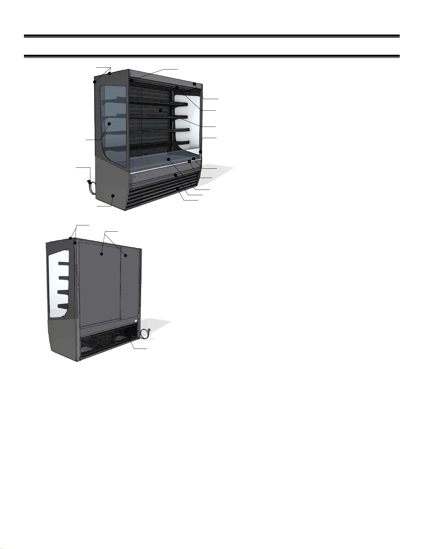
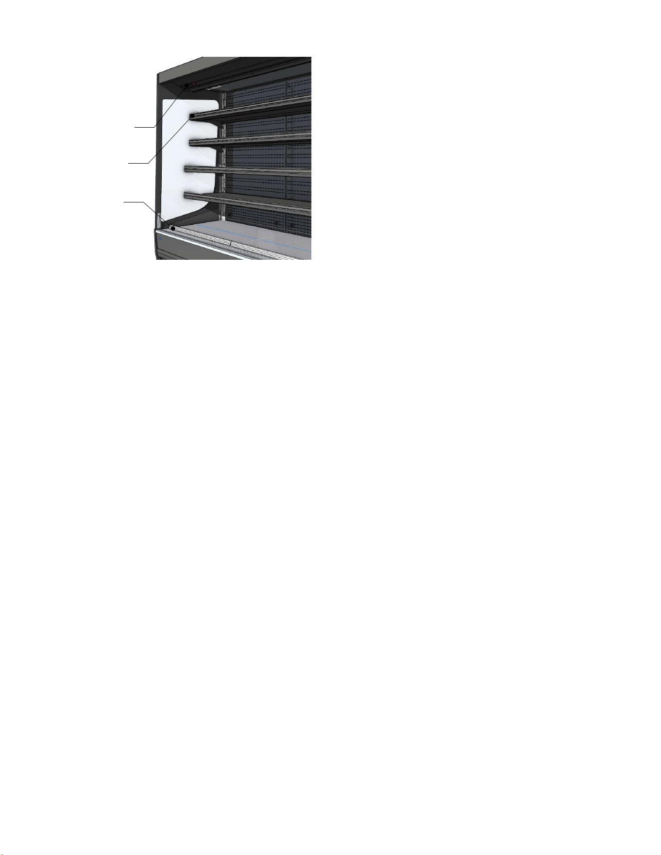
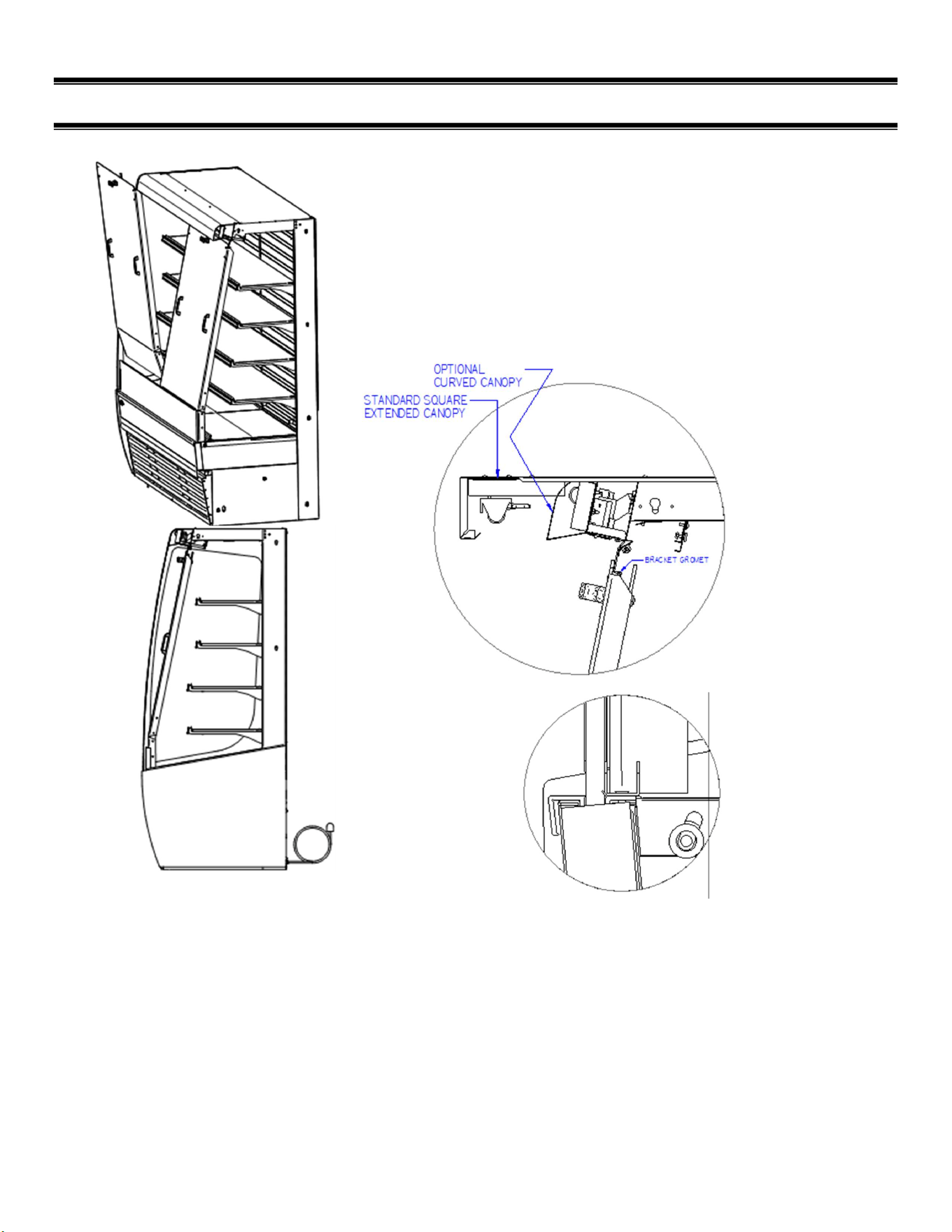
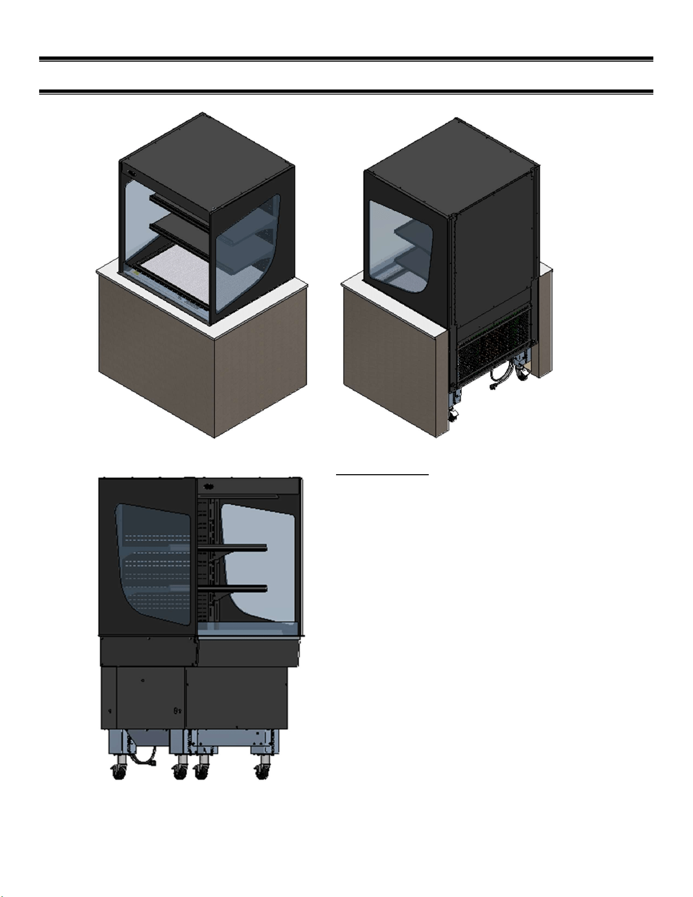
(4) FEATURE IDENTIFICATION
FRONT BASE PANEL/GRILLE
BOTTOM END
CORD AND PLUG
END GLASS
AIR DEFLECTOR
CONTROLS
END GLASS TRIM
AIR DEFLECTOR RETAINER
AIR DEFLECTOR RETAINER BRACKET
INTERIOR BACK PANEL
CANOPY
FRONT VALENCE
AIR DISCHARGE
AIR RETURN
BACK PANELS
END GLASS TRIM
REAR BASE PANEL/GRILLE
E3980 VISION R290
12
CONTROLS
PRICE TAG MOLDING
PRICE TAG MOLDING
E3980 VISION R290
13
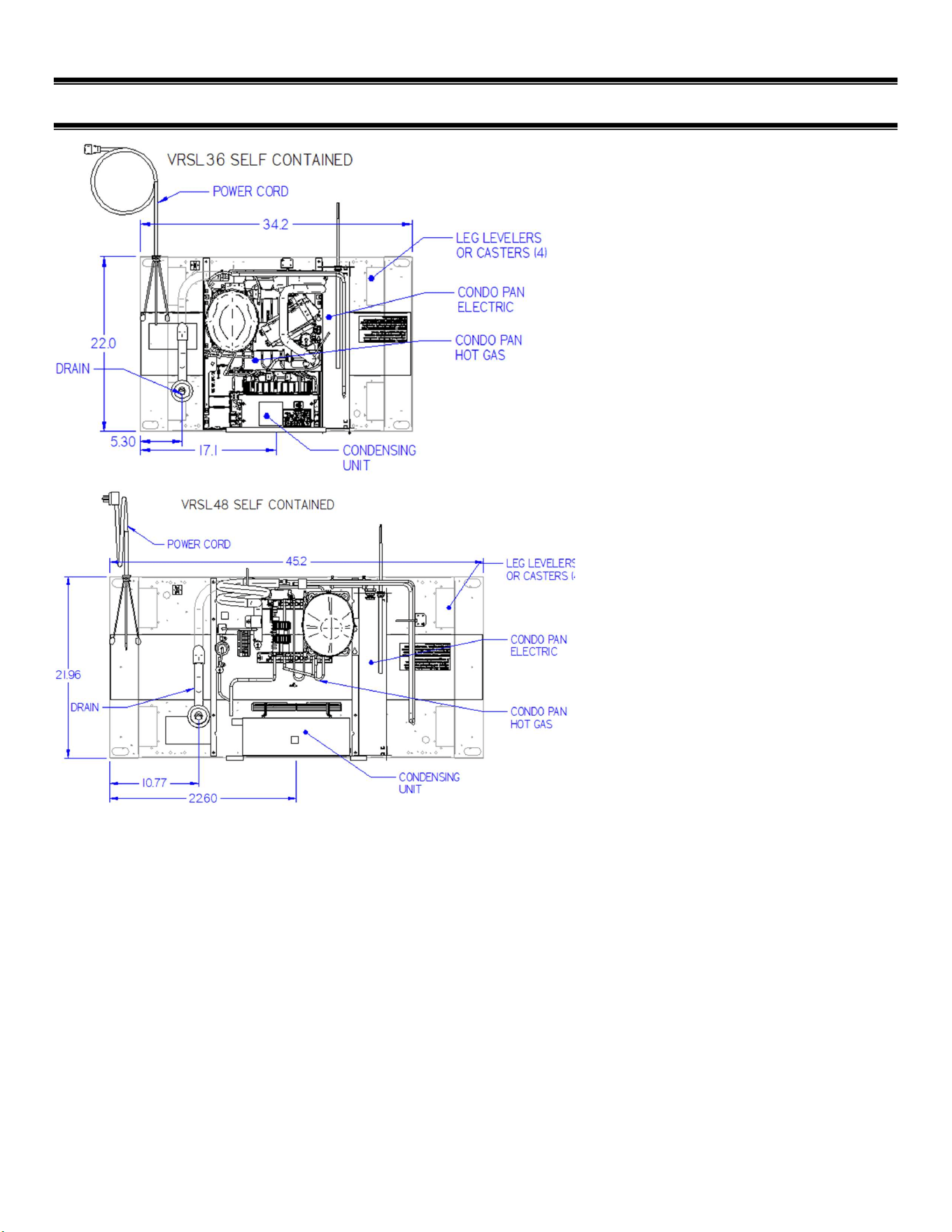
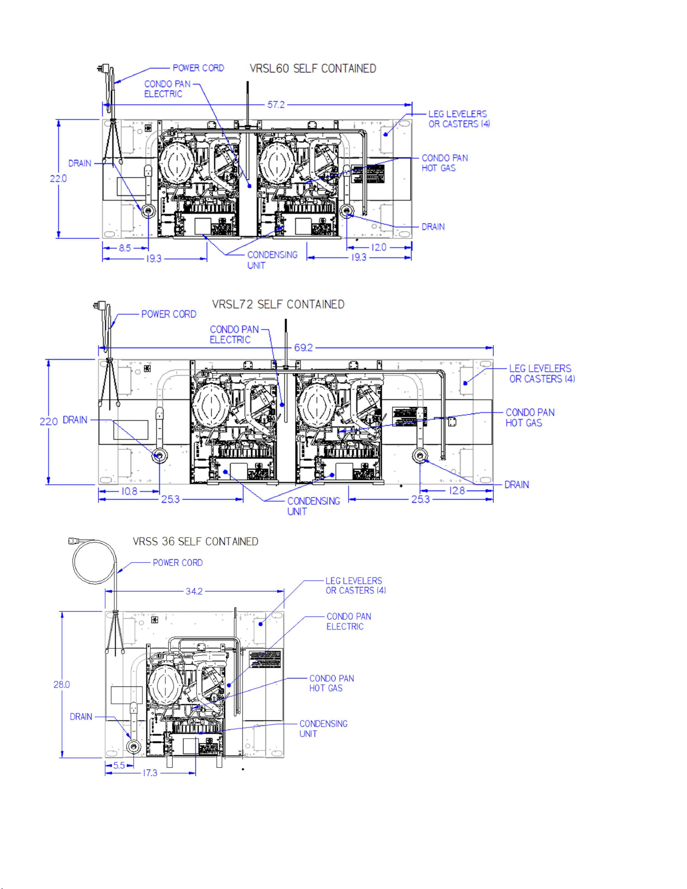
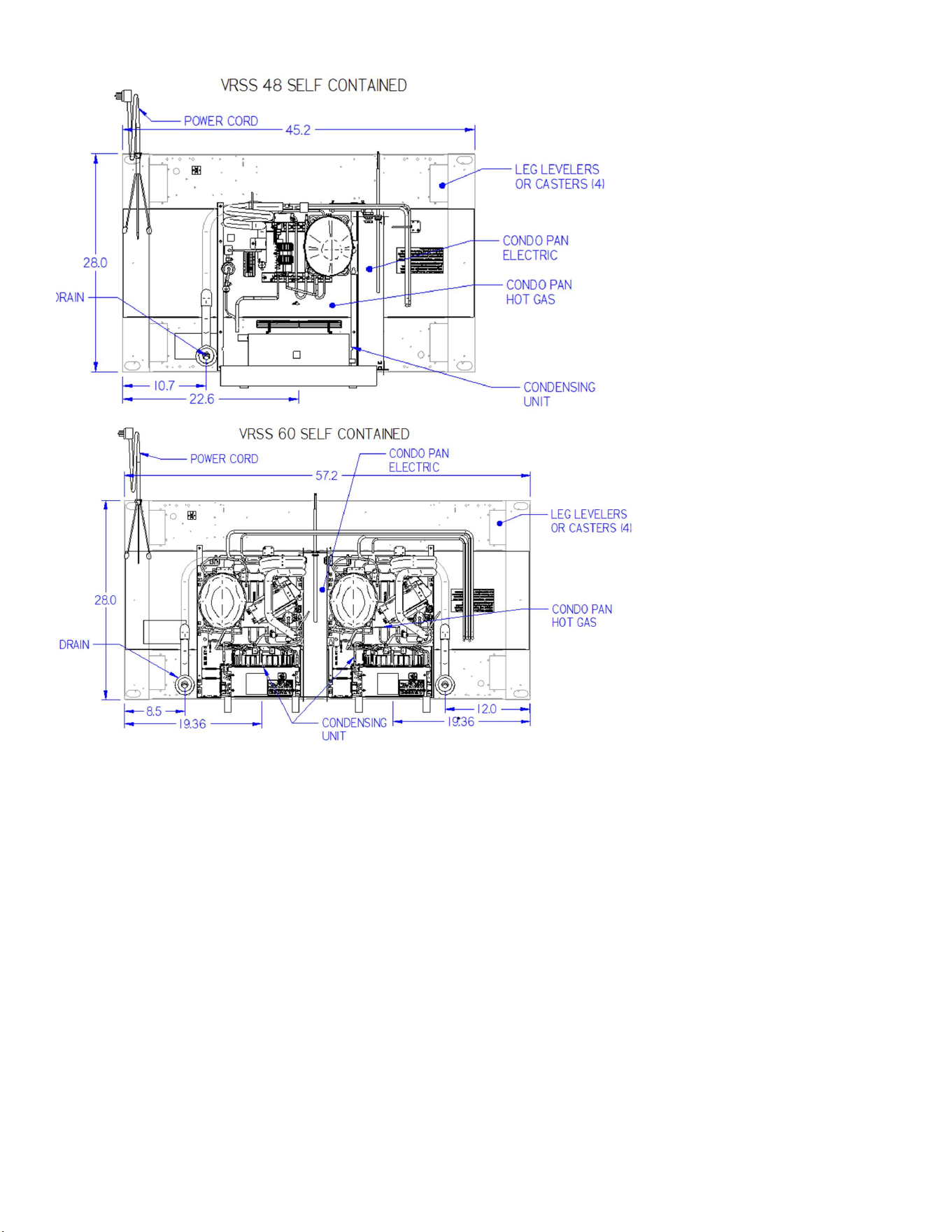
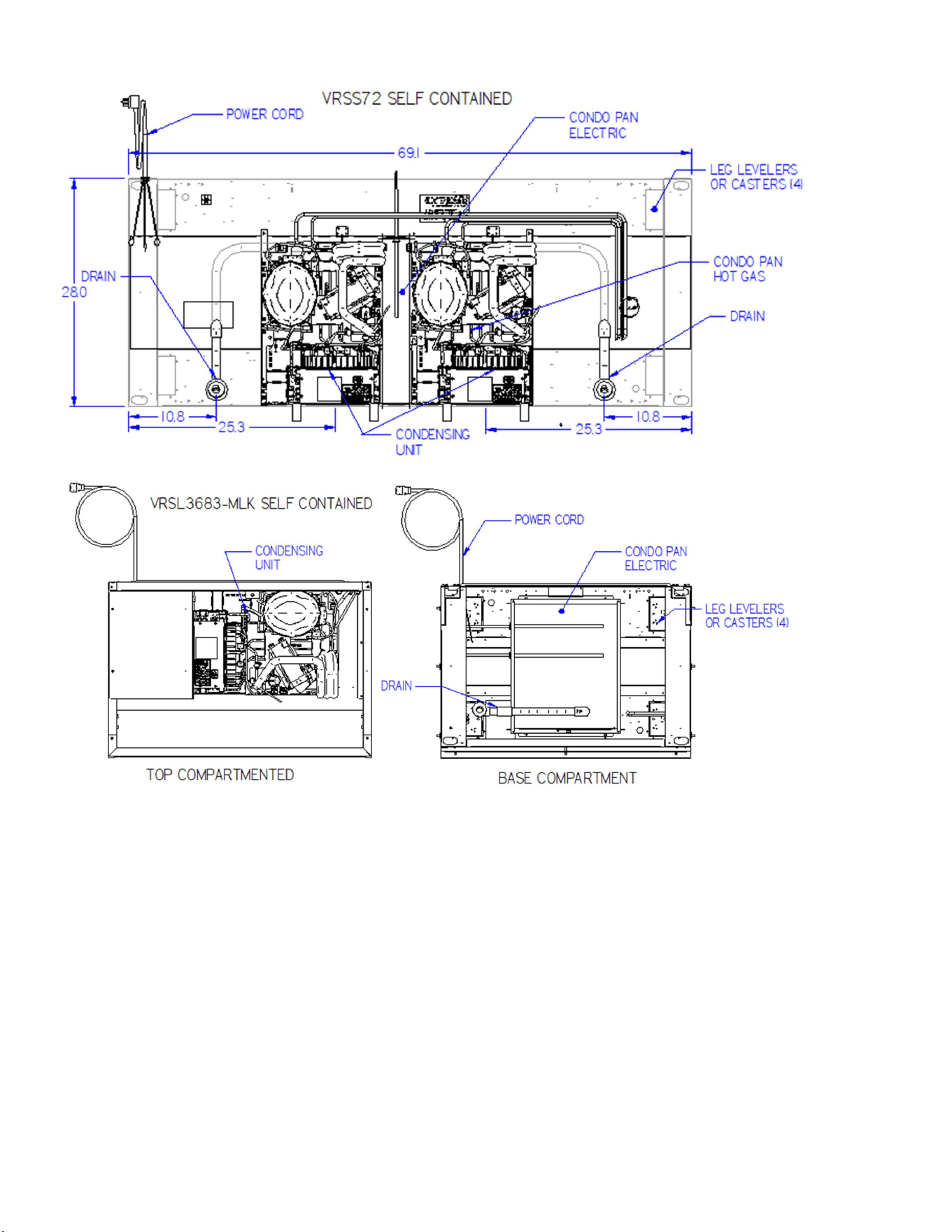
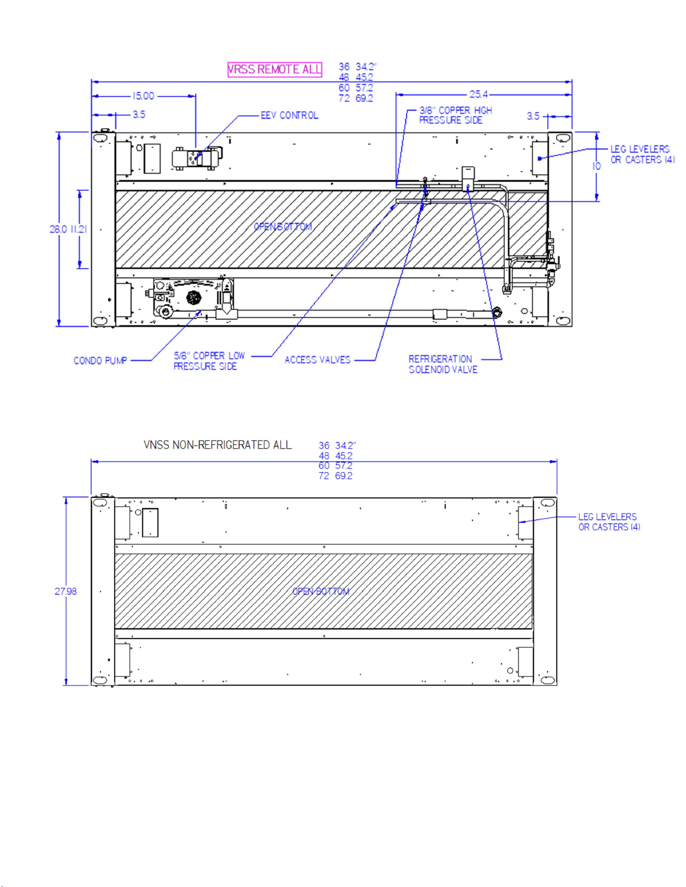
(5) BASE COMPONENT LAYOUTS
E3980 VISION R290
14
E3980 VISION R290
15
E3980 VISION R290
16
E3980 VISION R290
17
E3980 VISION R290
18
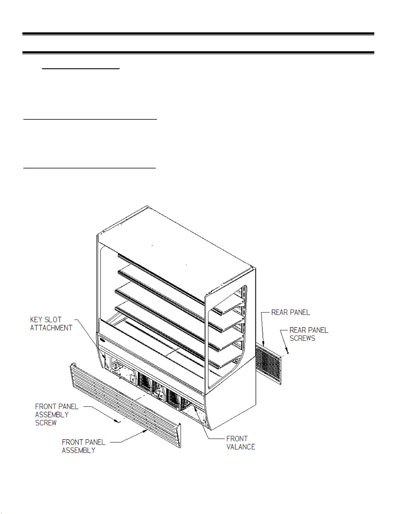
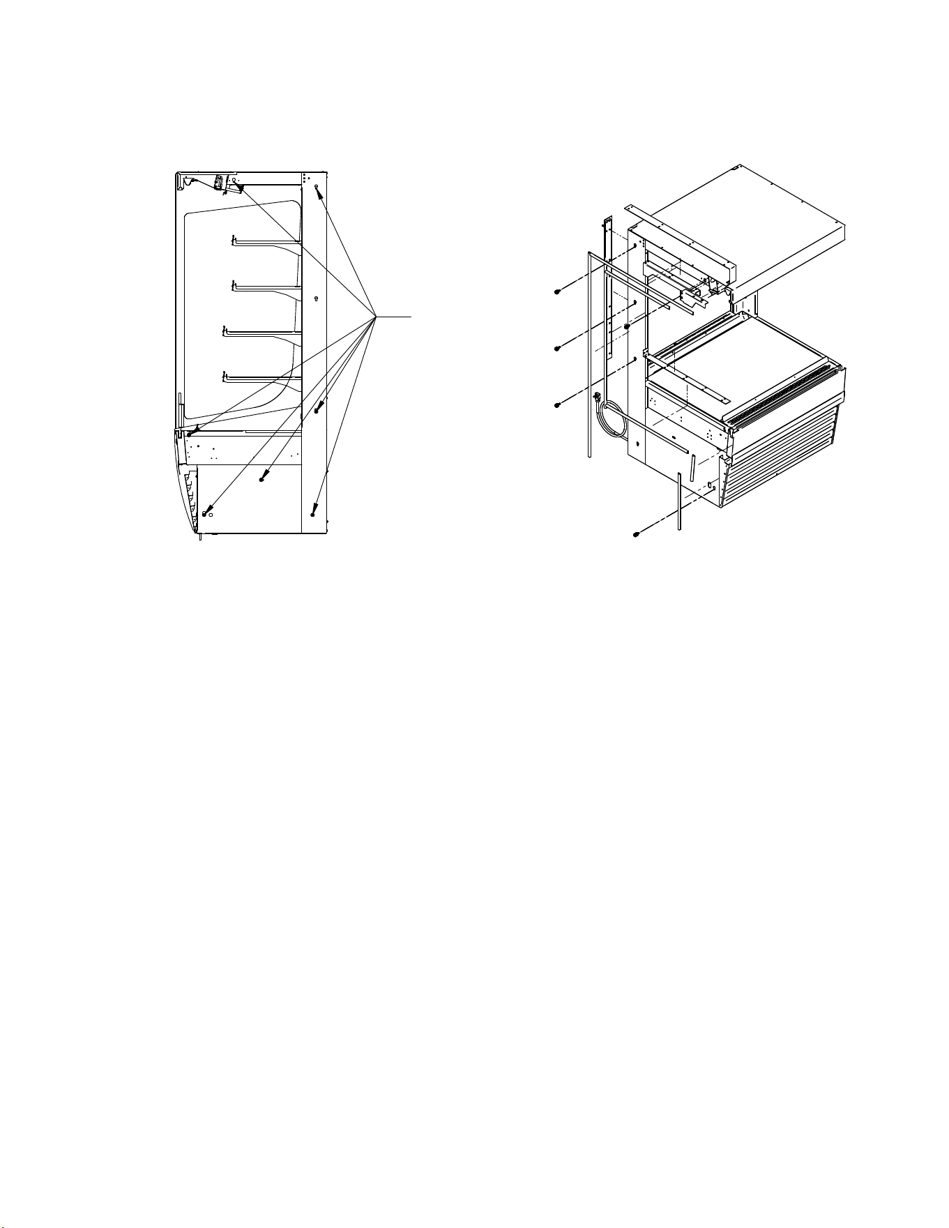
(6) PANEL REMOVAL
6.1 VRSS & VRSL MODELS
On these models the condenser and condensate pan are in the bottom base compartment. The Front
& rear panels can be removed to service and access components.
Disconnect Power before Removing any Panels.
Front Panel Removal (VRSS & VRSL):
-Remove center screw from bottom of front panel.
-Lift Front Panel Assembly Up slightly to unhook panel assembly from Key Slots.
-pull bottom of Front Panel outward from under front Valance.
-Reinstall in reverse order, be sure to hook all (4) key slots on panel on to screws.
Rear Panel Removal (VRSS & VRSL):
-Remove the rear panel screws located around the perimeter of the Rear Panel.
-Remove rear panel.
-Reinstall in reverse order
E3980 VISION R290
19
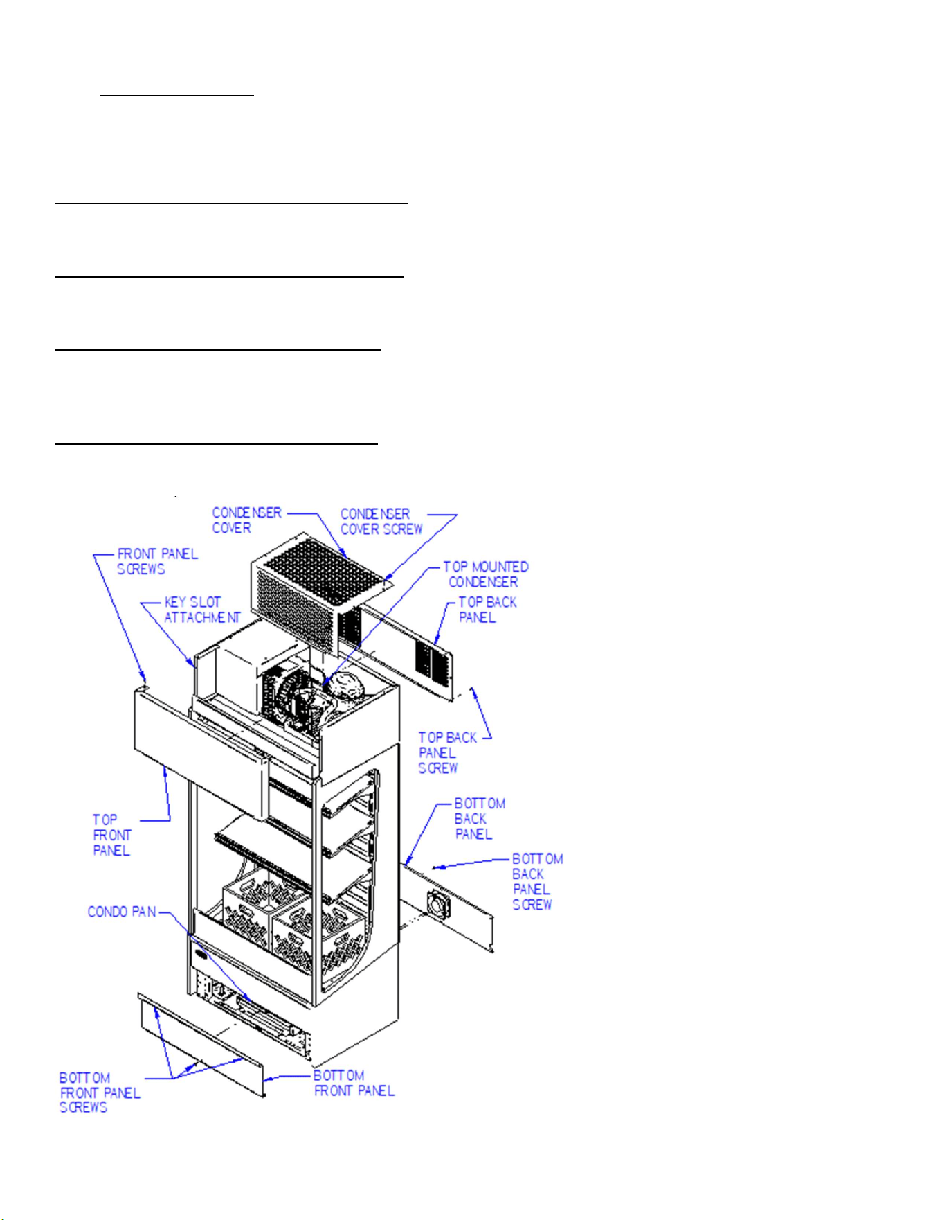
6.2 VRSL-MLK MODEL
On the Milk model the condenser is located on the top of the unit and condensate pan is located at
the bottom base compartment. The Front & rear panels on top and bottom of case can be removed to
service and access components. Disconnect Power before Removing any Panels.
Front Bottom Panel Removal (VRSL-MLK):
-Remove the center screw from bottom of front panel & the screws located under the top lip.
-Remove bottom front panel, Reinstall in reverse order.
Rear Bottom Panel Removal (VRSL-MLK):
-Remove the rear panel screws located around the perimeter of the Rear Panel.
-Remove the rear panel along with Fan. Reinstall in reverse order.
Front Top Panel Removal (VRSL-MLK):
-Remove (2) screws located on each side of top of front panel.
-Lift the Top Front Panel Assembly Up slightly to unhook panel assembly from Key Slots.
-Remove Top Front panel, Reinstall in reverse order.
Rear Top Panel Removal (VRSL-MLK):
-Remove the top rear panel screws located around the perimeter of the Top Rear Panel.
-Remove rear panel. Reinstall in reverse order

E3980 VISION R290
20
(7) PRIOR TO UNPACKING EQUIPMENT!
Inspect for shipping damage.
You are responsible for filing all freight claims with the delivery truck line. Inspect all cartons
and crates for damage as soon as they arrive. If damage is noted to shipping crates, cartons,
or if a shortage is found, note this on the bill of lading (all copies) prior to signing.
If damage is discovered when the case is uncrated, immediately call the delivery truck line and
follow-up the call with a written report indicating concealed damage to your shipment. Ask for
an immediate inspection of your concealed damaged item. Crating material must be retained to
show the inspector from the truck line.
E3980 VISION R290
21
(8) INSTALLATION INSTRUCTIONS
IMPORTANT: Read this Section of this manual located on page 5.
“REFRIGERATION WARNING &INSTALLATION-REPAIR-DECOMMISSIONING”
All refrigeration and electrical work must be performed by certified technicians.
8.1 LOCATING THE DISPLAY CASE
NOTICE
This refrigerated display case is designed to operate in a maximum
environment of 80 DEG. F and 55% relative humidity. Exceeding these
limits will cause poor case performance and sweating.
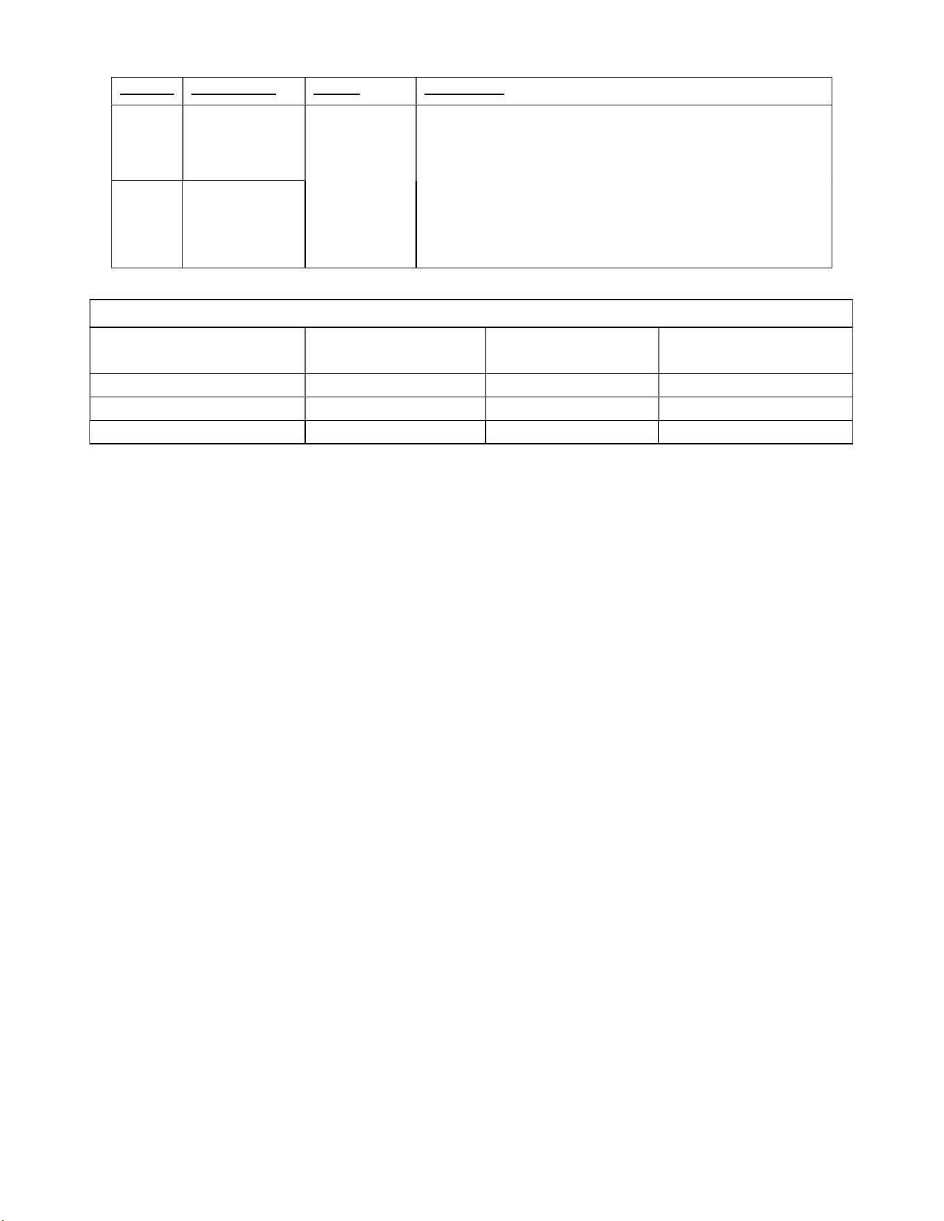
This case is designed for a class 3 environment.
Test room
climate
class
Dry bulb
temperature
[°F]
Relative
Humidity
[%] Dew point [°F]
Water vapor
mass in dry air
[lbm
water/lbm air]
Required
Test Lab
Temperature
[°F]
3
77.0
60
62.06
.012
89.6
NSF TYPE 1 Temperature cannot exceed 75 deg F and 55% humidity.
The case(s) should be located where it is not subjected to the direct rays of the sun, heating ducts,
grills, radiator, or ceiling fans, nor should it be located near open doors or main door entrances. Also,
avoid locations where there is excessive air movement or air disturbances and avoid high humidity
locations such as near cases with water misting or fogging devices. Failure to locate this case as
stated will reduce the performance of your display and will affect the temperature of interior of case
and product.
If this case or cases are to be located against a wall there should be at least 6” between the case and
the wall and 18” from top to ceiling to allow air circulation. Failure to give adequate space may cause
poor performance and exterior surfaces to sweat.
E3980 VISION R290
22
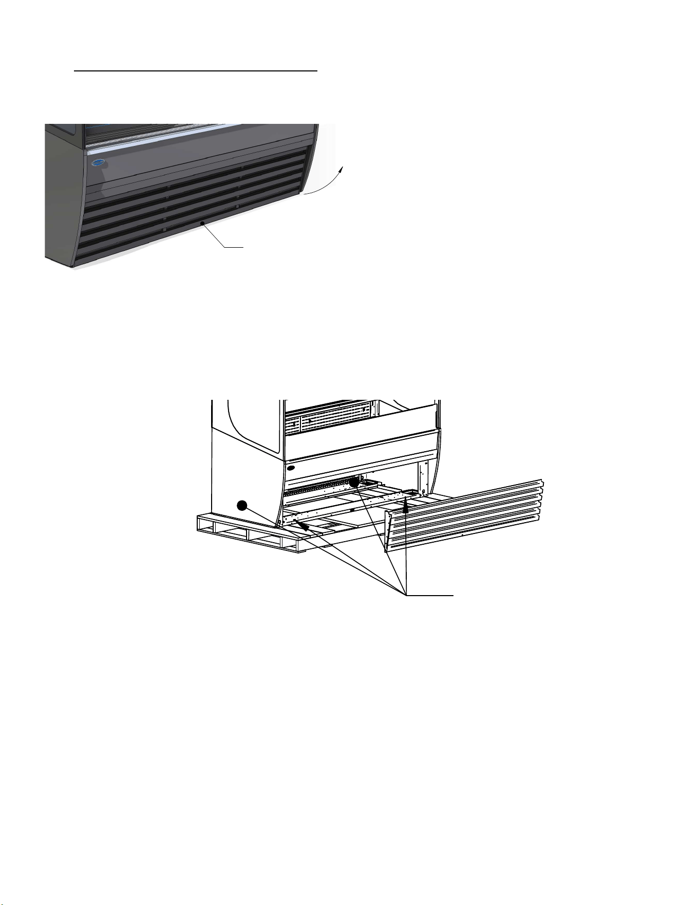
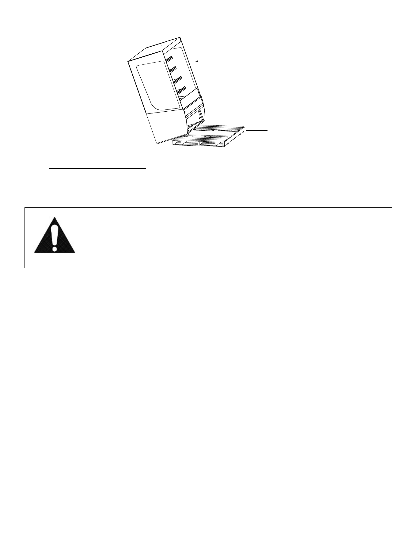
8.2 REMOVING CASE FROM SHIPPING SKID
Be sure to leave shelf packaging material intact for this step.
First remove the base front and rear panels
REMOVE FRONT PANEL SCREW
THEN LIFT UP
ROTATE BOTTOM OF PANEL FORWARD
AND SLIDE OUT FROM BEHIND VALENCE
Two or more people should be involved in moving the unit from the pallet onto the ground.
Remove the (4) 1/4” screws that secure the case to the skid. These screws are in the front and rear
corners of the base rails. Base front and rear panels must be removed to access these bolts.
LAG BOLT
LOCATIONS
Once all the bolts are removed, slide the unit off the back of the shipping pallet, and tilt it so the rear
corner touches the ground. Someone must move the pallet out from under the case and gently tilt the
case forward until it touches the floor.
NOTE: see page 20 for removal of slide-in cases from pallet
E3980 VISION R290
23
REMOVE CASE OFF OF FRONT OR BACK OF SKID ONLY
PULL SKID AWAY FROM CASE
AND GENTLY SET CASE ON FLOOR
8.2.1 Removing Packaging Material
Remove bubble wrap and packing material for all shelves and panel, brackets, etc. If it is
necessary to remove tape residue from plastic materials, use cleaning compounds
recommended in the cleaning section of this manual. “Lifting and Moving the Case”
Caution:
Do not push or pull against the glass air deflector on front of case. Doing so
can cause the glass to break. Do not push or pull on the side glass or pull on
the base panel. Doing so will break glass or pull out the panel mounting
screws. Care must be taken not to damage the case when removing it from
the skid or moving the case.
E3980 VISION R290
24
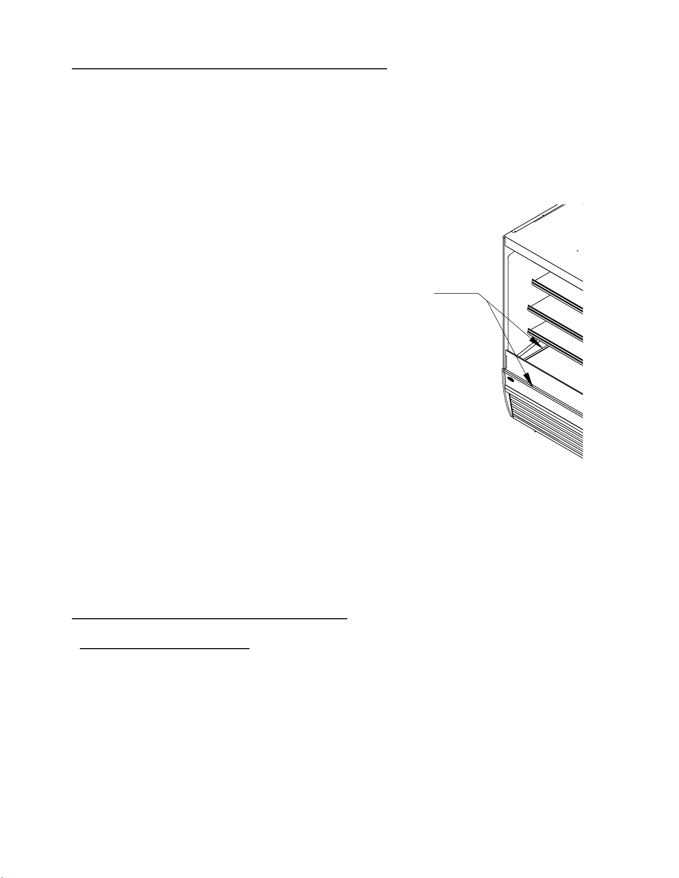
8.3 SINGLE CASE INSTALLATION (STAND ALONE UNITS)
Leveling the Case
It is important that the case is level. This will allow for proper drainage of condensate water from
evaporator coil. A wrench is included to aid in adjusting the leg levelers.
Check the left-to-right level of the case along front of plastic air deflector retainer.
Check the front-to-rear level of the case along the interior ends of the case.
LEVEL CASE USING THESE SURFACES
Adjust the (4) outside leg levelers as needed to level the case in each direction.
NOTE: If necessary, use a wood or plastic shim under each leg leveler to avoid scratching the tile
floor.
Sealing Unit to The Floor
After the unit is positioned and the leg levelers are turned out, the unit needs to be sealed to the floor
for NSF approved installation.
8.4 INSTALLATION FOR JOINED CASES (LINEUPS)
8.4.1 Join refrigerated to refrigerated
1. Remove all Shelves, display deck, interior back panel(s), exterior back(s), front and rear
base panel, and loosen honeycomb (see cleaning section for honeycomb removal) material
on the unfinished end to expose the holes used to bolt units together.
2. Position the right or left most unit in the desired position for the lineup to start, and level this
case.
3. Push the 2
nd
case next to the 1
st
and line them up as closely as possible.
4. Adjust the leveling legs of the 2
nd
case until the units and joining holes align with each
other.
E3980 VISION R290
25
5. Using (7) holes noted below, bolt units together with the supplied hardware, and attach
joining trim to remove the gap between the decks in the joined units. Re-use the screws in
the uprights, as well as the self-drilling screws provided with the kit.
JOINING HOLES
6. Replace all panels that were previously removed and re-insert honeycomb
E3980 VISION R290
26
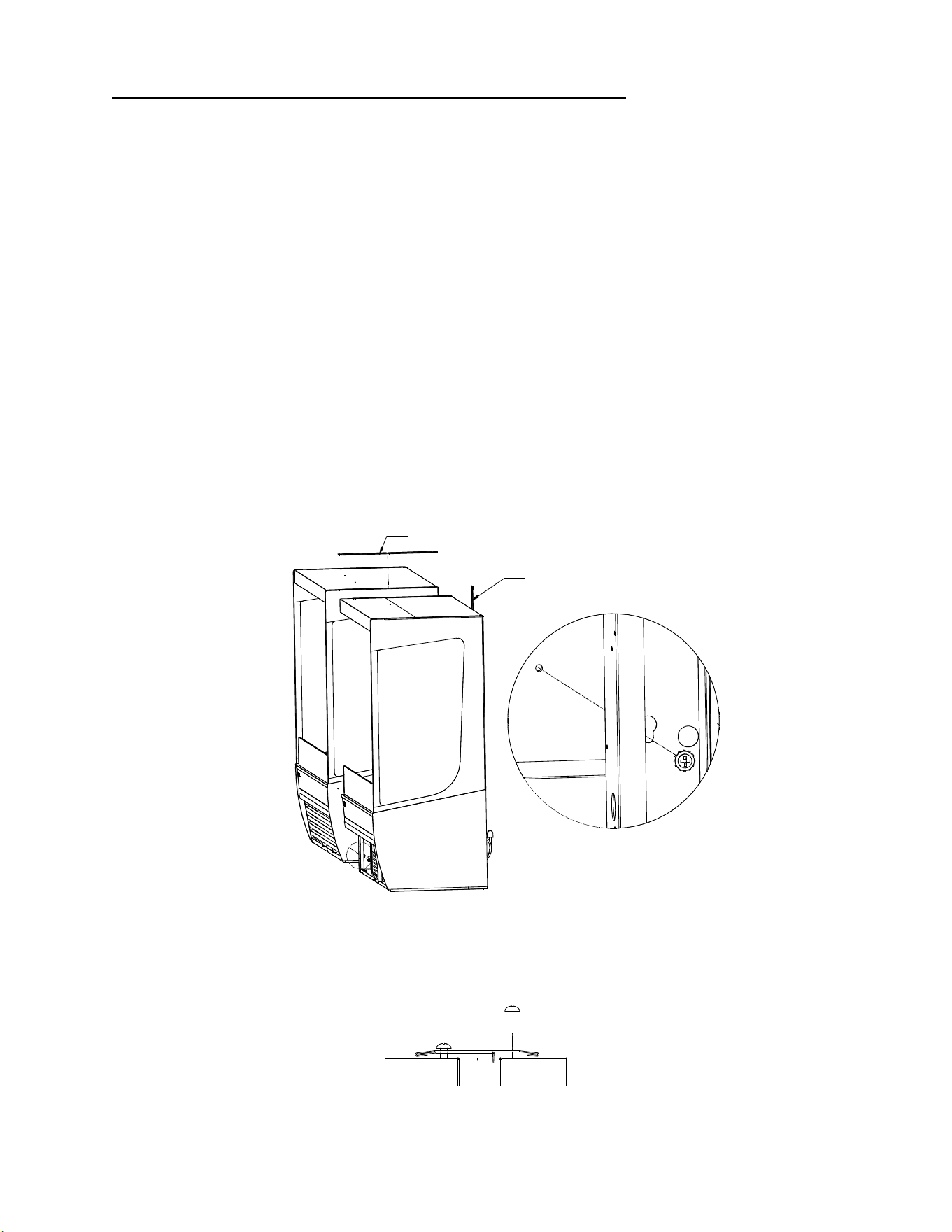
8.4.2 Join units with glass divider, or join refrigerated too non-refrigerated
For this joining configuration, one unit will come with a lower end panel preinstalled with glass.
Five bolt holes will be exposed on the outside of this panel and are the locations that will be
used to join the units together. This kit also comes with top and rear exterior trim, but no
interior trim.
1. Remove all Shelves, display deck, interior back panel(s), exterior back(s), front and rear base
panel, and loosen honeycomb (see cleaning section for honeycomb removal) material on the
unfinished end to expose the holes used to bolt units together.
2. Position the right or left most unit in the desired position for the lineup to start, and level this
case.
3. Push the 2
nd
case next to the 1
st
and line them up as closely as possible.
4. Adjust the leveling legs of the 2
nd
case until the bolt holes align with the mating holes in the
joining case.
5. Push the units together so that the bolts go through the case to be joined.
6. Using the hardware provided (1/4-20 screw, washer, lock washer), screw the 2
nd
case with the
unfinished end into the first case.
A
DETAIL A
TOP JOIN TRIM
REAR JOIN TRIM
7. Finish the joining process by loosening the glass trim on the case to slide the joining trim over
the existing trim and secure with the existing fasteners. Do this for both the top trim and the
rear trim.
FRONT VIEW
E3980 VISION R290
27
8. Replace any panels previously removed. Units are now joined.
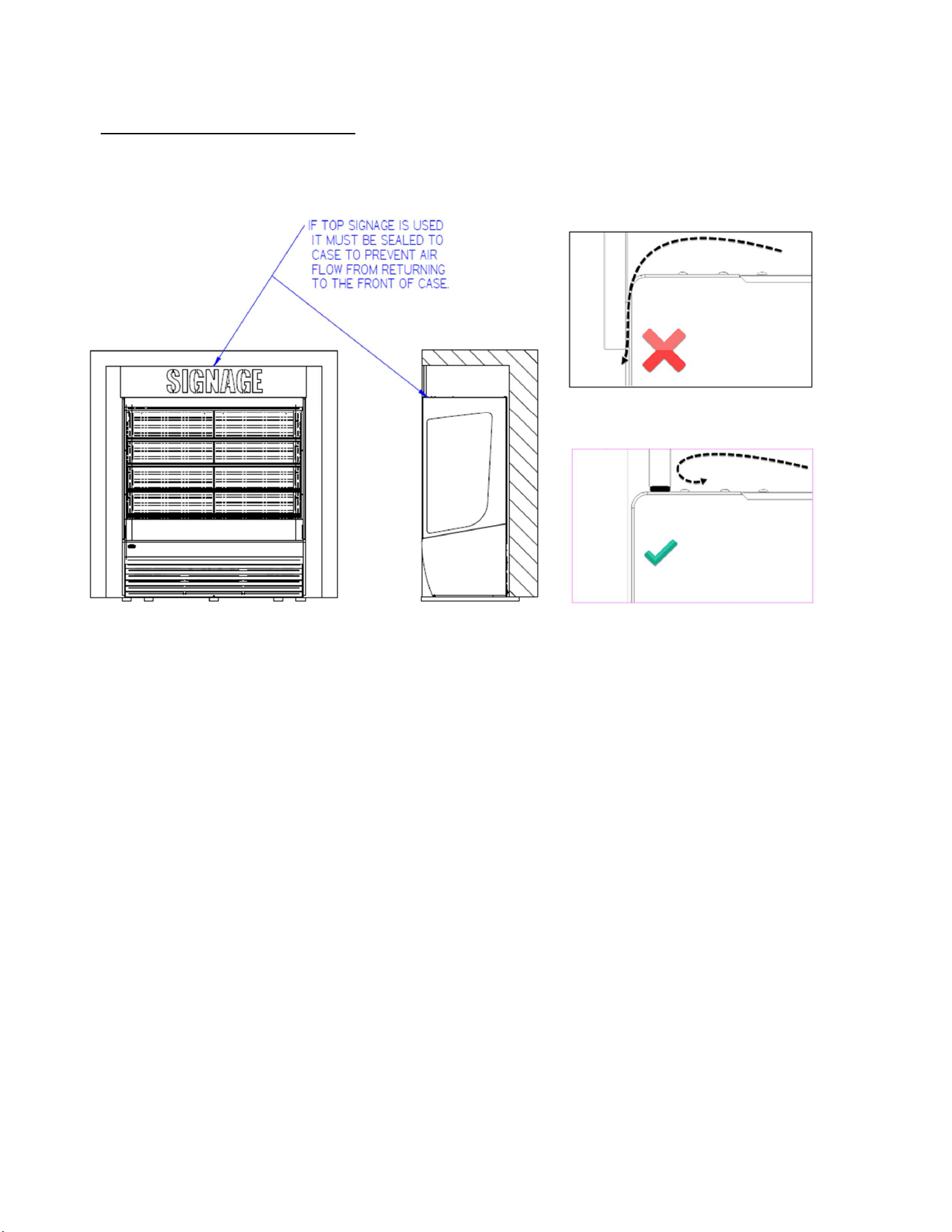
8.5 INSTALLATION IN AN ALCOVE
When installing a case in an alcove make sure any signage above the case is sealed to prevent
airflow from returning into the case.
E3980 VISION R290
28
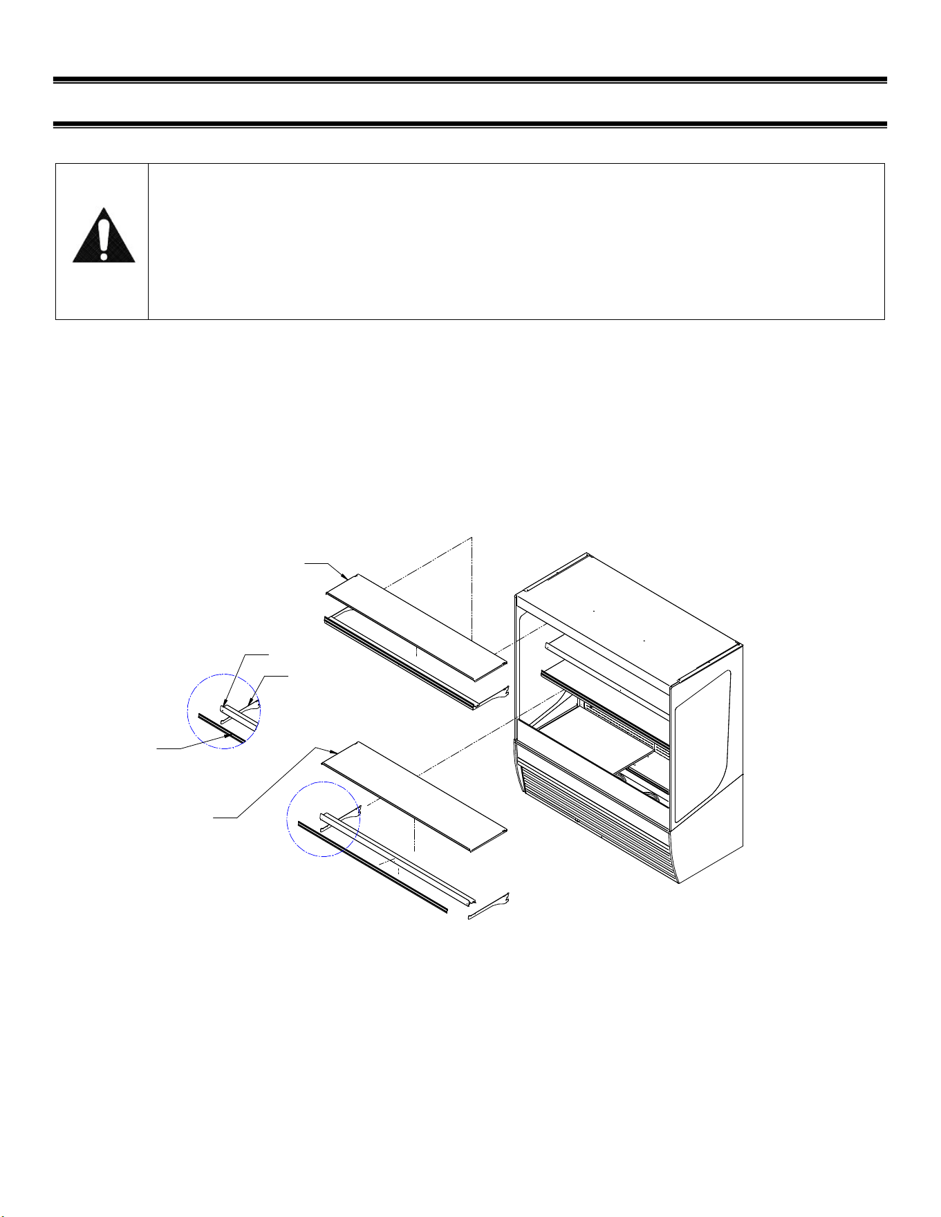
(9) SHELF INSTALLATION AND REMOVAL
Shelf brackets and supports
NOTICE: Improper shelf configuration will cause
performance issues
VRSS 78in tall units have two different shelf depths. The lower two shelves are
longer, the upper two to three shelves are shorter. The longer shelves must be
installed as the lowest shelves or the unit’s air curtain will be disrupted and the
unit will not maintain product temperature.
Shelves are pre-installed in the factory. To change shelf positions, remove the shelf, then shelf
support, then brackets. Relocate the brackets to the desired shelf position. The left bracket and right
bracket must be at the same height. This can be ensured by counting the position of the notch in the
shelf standard. If you have shelf lights, the wire running to the light must be unplugged prior to moving
the shelves. Note how the wire runs through the shelf support, and shelf.
Allow a minimum of 2” between the top of product and bottom of shelf to allow proper air flow around
product.
A
DETAIL A
SUPPORT
BRACKET
PRICE TAG MOLDING
(NOT REMOVABLE)
SHELF (17IN)
SHELF (15IN)
E3980 VISION R290
29
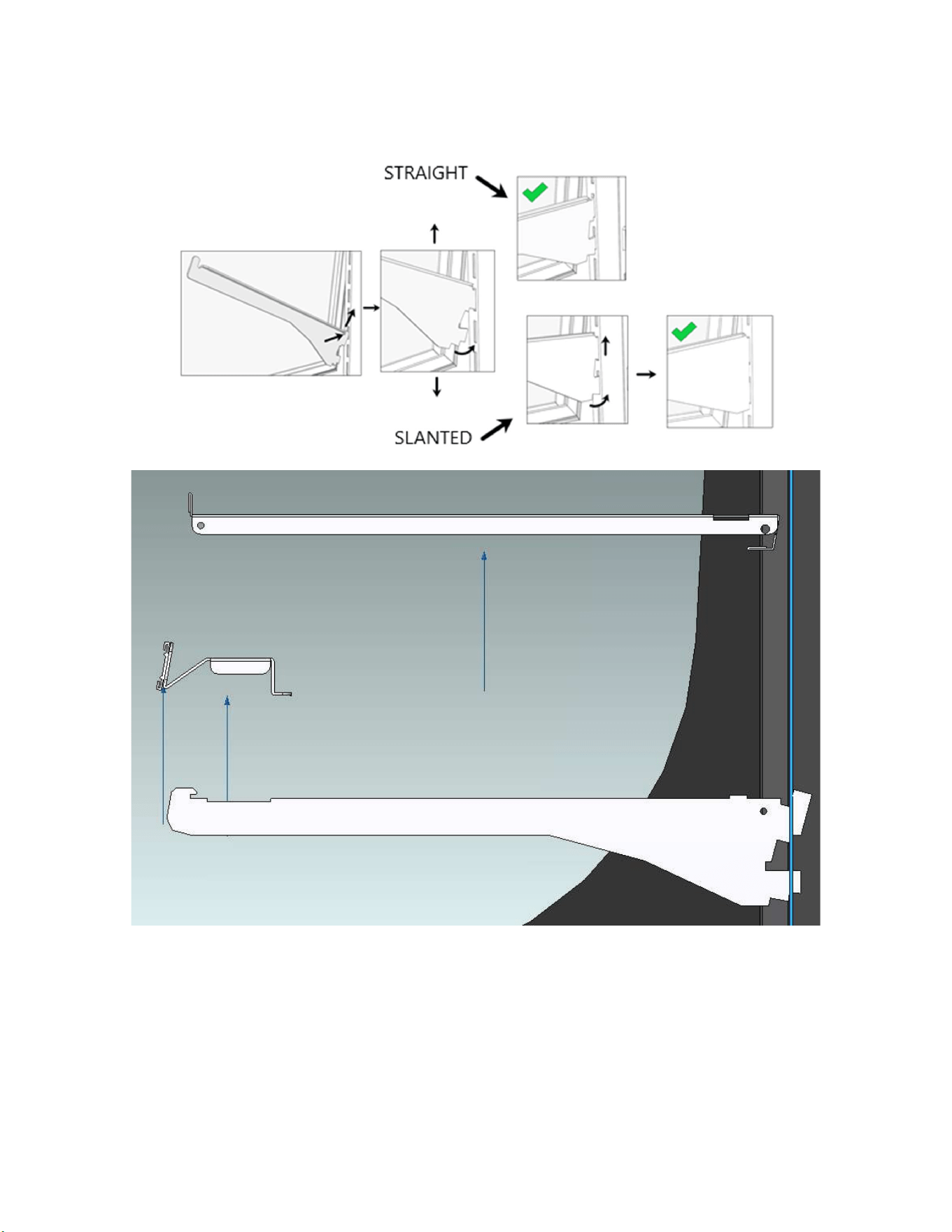
The diagram below illustrates how to straighten or angle the shelves. To angle the bracket, be sure to
have the top hook of the bracket in its slot and to pull up while rotating down to the most extreme
downward position. To angle the shelf, first angle both brackets, and install the shelf as normal.
E3980 VISION R290
30
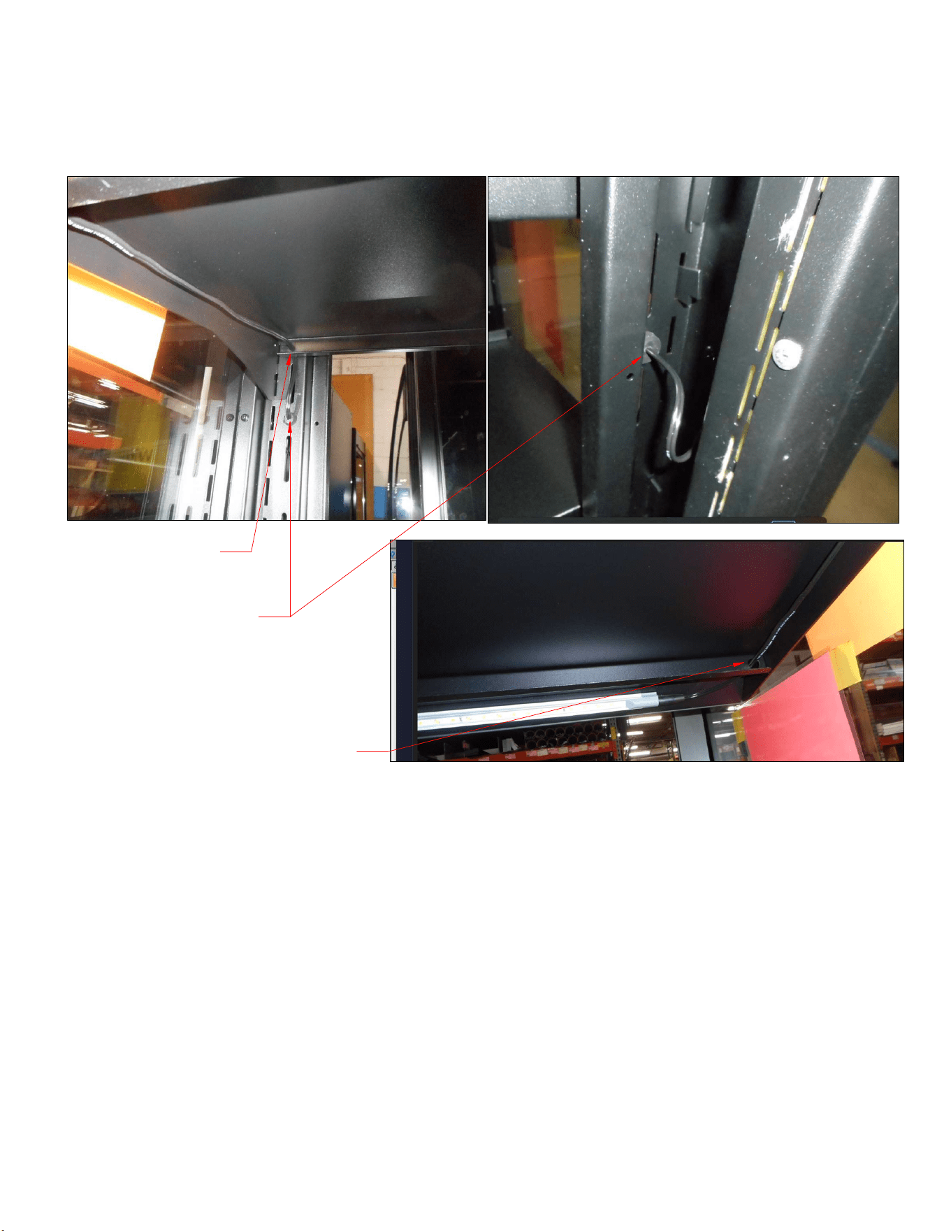
INSTALLING SHELF LIGHT CORDS
CORD GOES THRU HOLE IN SHELF SUPPORT
CORD HOOKS IN SLOT ON
BACK FLANGE OF SHELF
PUSH EXCESS SHELF CORD
BACK INTO GROMMET
E3980 VISION R290
31
(10) SECURITY NIGHT COVER (OPTIONAL)
.
1. Install the security cover into the preinstalled retaining brackets by first
inserting the bottom with the top of the cover tilted out.
2. Insert the bottom of the security cover into the lower u-clip retainer by
rotating the top of the assembly toward the case and dropping the cover
down into place.
3. The top of the cover will sit against the upper retainer bracket.
4. Once the cover is in position, lock the latch using the key in the
t-handle of the security cover panel.
When installing the security cover panel, ensure that the bottom of the panel is seated in the
lower u-clip, and that the latch fully engages behind the upper retaining bracket.
5. Install the security cover into the preinstalled retaining brackets by first inserting the bottom with the top
of the cover tilted out.
6. Insert the bottom of the security cover into the lower u-clip retainer by rotating the top of the security
cover assembly in toward the case and dropping the cover down into place.
7. The top of the cover will sit against the upper retainer bracket.
Once the cover is in position, lock the latch using the key in the t-handle of the security cover panel.
E3980 VISION R290
32
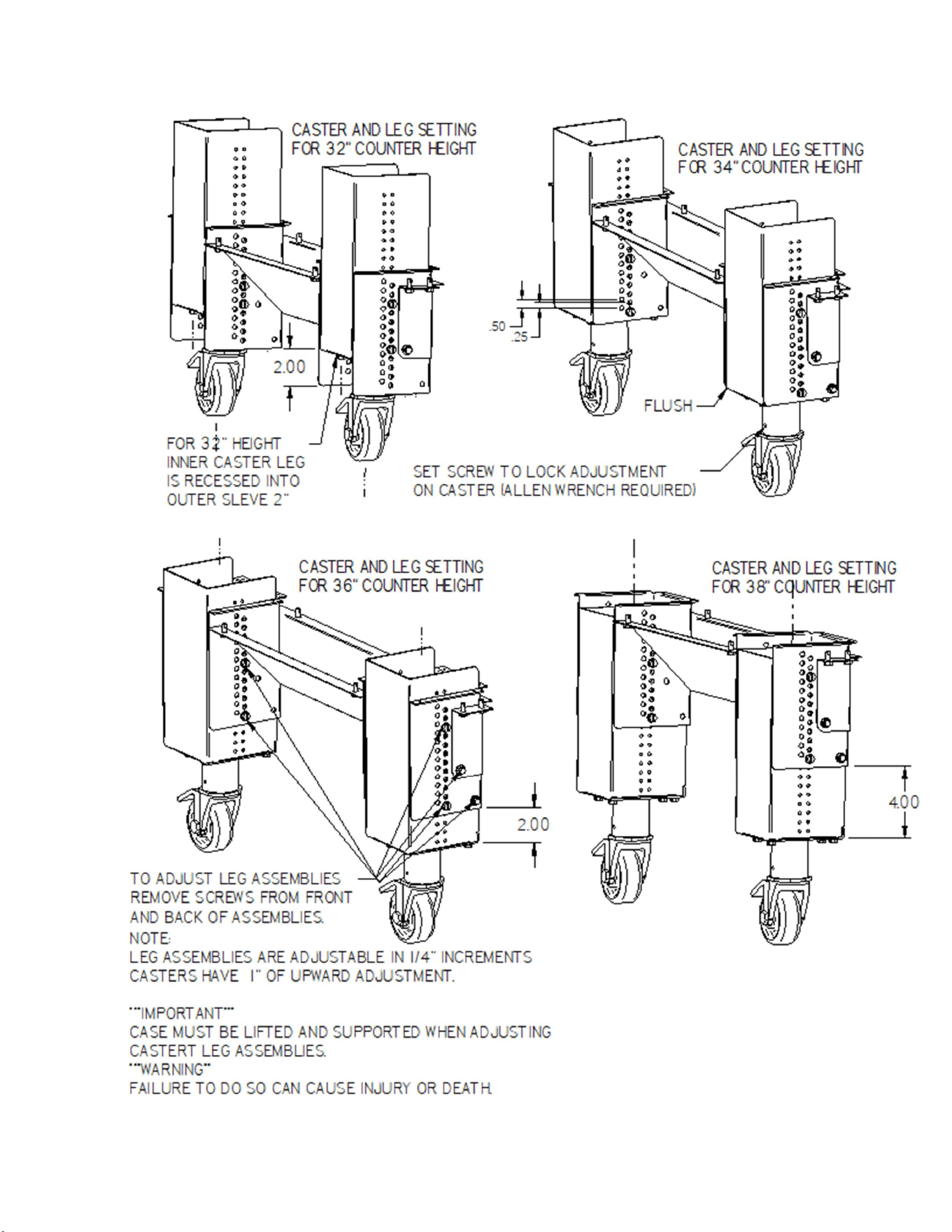
(11) Slide-In Models -Leg & Caster Adjustments
Slide In Models
Designed to slide/roll into a counter with an open
back.
Refrigerated cases are available with rear
condenser air intake and discharge only.
Case counter height is set at 34” from the factory.
Leg assemblies are adjustable in 1/4" increments.
Adjustable casters have 1” of upward adjustment to
fine tune height to match counter surfaces.
Casters lock in the swivel and roll directions.
The next page shows common counter height
adjustments.
***IMPORTANT***
CASE MUST BE LIFTED AND SECURED
TO ADJUST CASTER/LEG ASSEMBLIES.
***WARING***
FAILURE TO DO SO CAN CAUSE SEVERE
INJURY OR DEATH.
E3980 VISION R290
33

E3980 VISION R290
34
NOTE: some leg adjustment can be done before case is removed from the pallet.
E3980 VISION R290
35
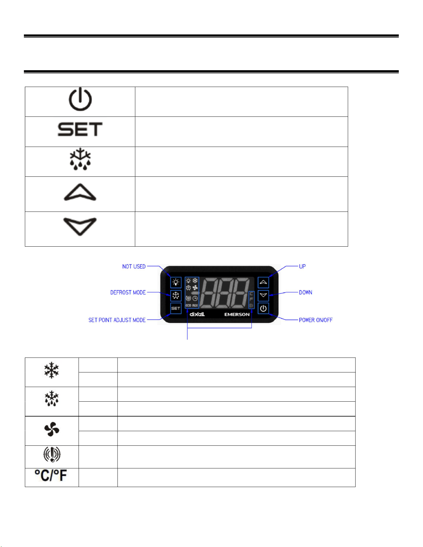
(12) ELECTRONIC TEMPERATURE CONTROL (REFRIGERATED
UNITS ONLY)
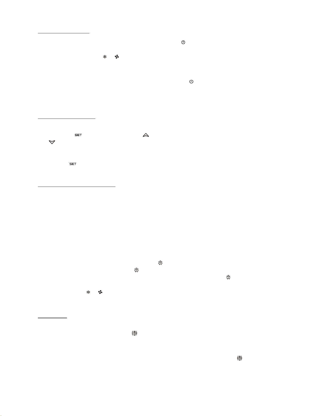
Power on/off: Press and hold to turn system on or off.
Set: Press and hold to enter the set point adjustment
menu.
Defrost: Press and hold to initiate a manual defrost.
Up: Change set points when in set point adjustment
menu. When not in set point menu, shows maximum
temperature of the display probe.
Down: Change set points when in set point adjustment
menu. When not in set point menu, it shows minimum
temperature of the display probe.
Display indication symbols
On Compressor on
Flashing
Minimum compressor off time in progress
On Unit in defrost mode
Flashing
Defrost delay
On Condenser fan running
Flashing
Minimum condenser fan off time in progress
On Alarm occurring. See the error code section below.
On Indicates temperature unit of measure.
E3980 VISION R290
36
12.1.1 Powering on control
To turn refrigeration control power on, press and hold “ ” for approx. three seconds. When the
control power turns on, the display will read the cabinet probe temperature. The compressor and
condenser fan run indicators ( & ) will illuminate on the display, meaning that the compressor and
condenser fan are running. (Note: the control may already be in the on mode when shipped from
factory).
To turn refrigeration control power to off, press and hold “ ” for approx. three seconds. When the
control powers off the display will read “OFF”. When refrigeration control is in the off-mode cabinet
lights and evaporator fans will still operate, but the compressor will not turn on causing the case to
gradually reach room temperature.
12.1.2 Adjusting the set point
The set point is what determines how cold the display case will hold food and beverage. To adjust the
set point press the “ ” button. Then press “ ” button to increase the set point number (colder) or
press the “ ” button to decrease the set point number (warmer). There are nine (9) available set
points numbers, the higher the number of the set point, the colder the display case will run, with
setting “9” being the coldest and setting “1” being the warmest. Once you have chosen your desired
setting press the “ ” button again to confirm your choice. The control cutout temperature for the
selected setpoint will briefly be displayed if the setpoint is changed.
12.1.3 Entering manual defrost mode
The control is programmed to automatically initiate a defrost by two different methods, involving time
and temperature, as outlined in the “Defrost Cycle” section (Pg.) of “ELECTRONIC CONTROL
PARAMETERS AND EXPLANATION OF OPERATION.” While it is uncommon that the automatic
defrost cycles would insufficiently defrost the case, a Manual Defrost mode is available if this
situation arises.
Note: The control will not allow the initiation of a manual defrost within 30 minutes of completion of
another defrost cycle, manual or automatic.
To initiate the manual defrost press and hold the “ ” button approx. three seconds. The defrost is
initiated when the defrost mode indicator illuminates on the display. The control display will then
return to reading the probe temperature. When the defrost mode indicator turns off the defrost is
complete and the compressor will turn on automatically and the compressor and condenser fan
indicator will be shown ( & ).
12.1.4 Error codes
It is possible for error codes to be displayed on the control screen. In the event of a malfunction an
alarm will sound and the alarm indicator will be displayed. An error code or codes will flash
intermittently on the display. If there are multiple codes, the display will continuously cycle through
them.
Mute: You may mute the alarm by pressing any button. The red alarm symbol and all error codes
will still be displayed. When the fault is remedied, the control will return to normal operation and will
automatically clear the codes from the display.
E3980 VISION R290
37
Display
Description Cause Resolution
“P1”
Air discharge
temperature
probe failure
Probe signal
is interrupted
or short-
circuited
Check to ensure probe wires and quick disconnect are
secure in control.
Check probe resistance to table below. If 0 resistance is
present, check wiring insulation. If infinite resistance is
present, check for breaks in wiring (meter will likely read
overload or very high in the mega-ohm range).
Ensure that probes are wired per the wiring diagram
provided. Replace probe if other remedies fail, or if
probe resistance deviates from “Table 3” below.
“P2”
Defrost
temperature
probe failure
TEMPERATURE PROBE COMMON RESISTANCE CHART
Probe Temp
Maximum
Resistance [kΩ]
Normal
Resistance [kΩ]
Minimum
Resistance [kΩ]
32°F(0°C) 27.83 27.28 26.74
77°F(25°C) 10.1 10 9.9
212°F(100°C) 1 0.97 0.94
E3980 VISION R290
38
(13) INITIAL STARTUP (REFRIGERATED UNITS ONLY)
NOTICE
This refrigerated display case is designed to operate in a maximum
environment of 80 DEG. F and 55% relative humidity. Exceeding these
limits will cause poor case performance and sweating.
1. Prior to initial startup be sure to clean the case as described in the “Weekly Cleaning” section
of the manual.
2. Be sure that the display deck(s) and shelves are in the desired locations.
3. Be sure front and rear base panels are in place and secured.
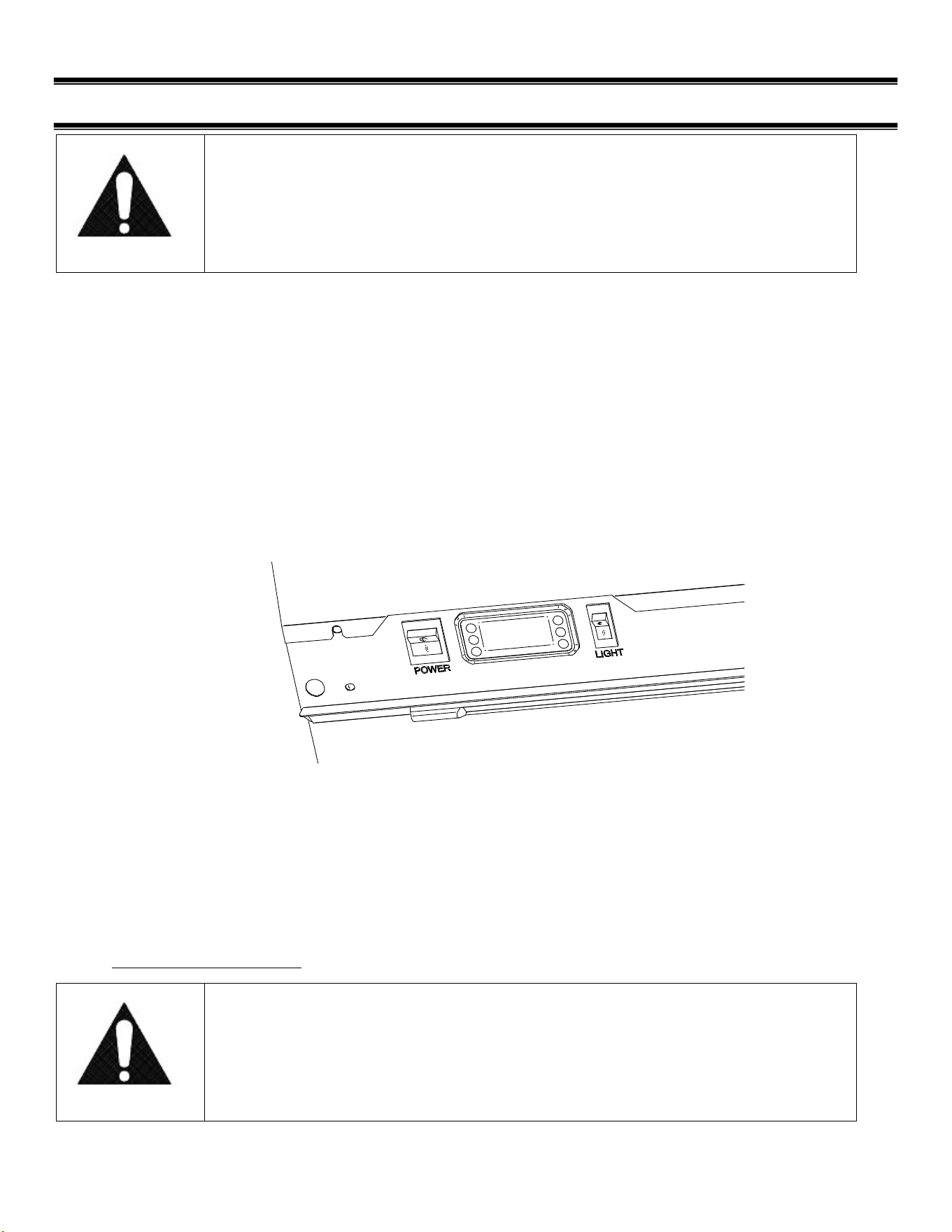
4. Plug in the unit to the appropriate wall outlet and turn unit’s power switch (marked “POWER”)
to the on or “I” position.
5. If the control reads “OFF” then press and hold the control’s power button to turn it on.
6. In a few moments the refrigeration system will turn on.
7. Use the switch labeled “LIGHT” to turn on all top/shelf lights.
For more detailed information on control operation see the section “Electronic Temperature
Control”
At start up from a warm unit, it is recommended that the temperature control is set to a mid-
setting, such as 5. After the unit has gone through several cycles, adjust the control to a
warmer or colder setting, if necessary, to maintain desired product temperature. Allow
refrigerated models to run for at least two hours before placing pre-chilled product into display
area.
13.1.1 Placing Product into Case
NOTICE
CASE MUST BE STOCKED WITH PRE-CHILLED PRODUCT 38° OR
COLDER.
E3980 VISION R290
39
Do not exceed 150 pounds of weight per shelf. Heavy products should be distributed evenly
across the entire shelving area.
Determine desired shelving location before placing product in case. Product must be removed to
readjust shelf location.
Allow a minimum of 2” between top of product and bottom of next shelf up.
Do not overhang the front or rear of the shelves with product. Improper clearance in front and rear
of the shelf will block the refrigerated airflow and will cause product loss.
Do not block the slots along the front and rear air discharge slots. Covering these slots will block
the refrigerated airflow and could cause product loss.
Allow refrigerated models to run for at least two hours before placing pre-chilled (38°F or less)
product into the case.
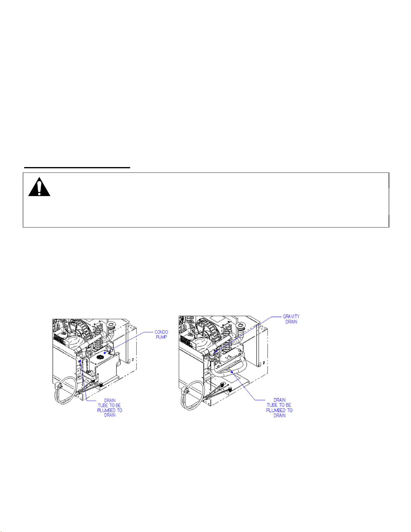
Condensate Evaporator
NOTICE: Steam from the condensate evaporator may be visible around the
base of the merchandiser during normal operation.
This merchandiser is furnished with an electric condensate evaporator, and no plumbing
connections are required.
If the merchandiser is supplied with either an electric condensate pump or floor drain option,
the hose inside case will need to be routed to the nearest drain.
If desired the condensate drain tubes can be changed to bypass the condensate system and
run directly to drain. Bypassing the Factory condensate system must be performed by a
qualified plumber and electrician.
This is an open merchandiser and can produce a large amount of condensate water.
To ensure that adequate evaporator capacity is available, a high wattage heater is
used.
Inspect condensate pan and drain tubes to be sure nothing has become dislodged during
shipment and that nothing is leaking. Tightening or adjusting clamps or hoses may be required.
E3980 VISION R290
40
(14) CLEANING INSTRUCTIONS
14.1 DAILY CLEANING
The case should be cleaned thoroughly, as described in the weekly cleaning section before it is used
for the first time.
NOTICE:
Avoid splashing or soaking any electrical components with water to
prevent electrical damage to the case.
NOTICE:
Shut off lights, disconnect power and remove all products from case.
Allow sufficient time for the unit to reach room temperature before
proceeding with cleaning.
NOTICE:
Remove all products from the case before proceeding with cleaning
procedure.
NOTICE:
This case is not designed to be cleaned by flushing.
Note: For major spills or foreign material buildup perform the weekly cleaning
instructions.
Note: Detergents are not recommended and do not use abrasive cleaners or pads to
prevent scratching of surfaces.
1. Clean all foreign materials from the door opening.
2. Completely wipe the interior of both the upper & lower areas of case using a damp cloth.
3. The remaining exterior surface should be wiped down using any ammoniated cleaners or
soapy warm water.
14.2 WEEKLY CLEANING
This procedure is recommended on a weekly basis. It may need to be performed more often if
necessary to maintain a clean, sanitary case. The case should be cleaned to the following procedure
before using case for the first time.
E3980 VISION R290
41
NOTICE:
Avoid splashing or soaking any electrical components with water to
prevent electrical damage to the case.
NOTICE:
Shut off lights, disconnect power and remove all products from case.
Allow sufficient time for the unit to reach room temperature before
proceeding with cleaning.
NOTICE:
Remove all products from the case before proceeding with cleaning
procedure.
NOTICE:
This case is not designed to be cleaned by flushing.
1. Side, and rear door glass can be cleaned with common window cleaners.
2. Remove interior shelving and display deck from unit as described in the “Shelving Installation
and Removal” section of this manual.
3. Clean all shelves, shelf supports, shelf light deflectors, shelf brackets, shelf standards using
warm soapy water and a brush. Rinse thoroughly and allow it to dry.
4. Remove the display deck and clean using warm soapy water and a brush. Rinse thoroughly
and allow it to dry.
5. Clean the entire interior of the case using warm soapy water. Wipe off all soapy water with a
damp cloth and allow it to dry. (DO NOT use solvents such as Acetone, Benzene, Carbon
Tetrachloride, and Lacquer Thinners)
6. Reassemble all components in reverse order.
7. The exterior surfaces should be wiped down using any ammoniated cleansers or warm soapy
water.
E3980 VISION R290
42
14.3 CLEANING CONDENSER COIL
NOTICE:
Condenser coil must be inspected/cleaned at regular intervals defined
below to ensure proper refrigeration performance and prevent
compressor failure. In some environments, it may be necessary to
clean more frequently. FAILURE TO CLEAN CONDENSER COIL WILL
VOID COMPRESSOR WARRANTY.
The condenser must be cleaned from the front of the case.
1. Disconnect power to the unit.
2. Depending on the model, remove either the front panels located on the base or Top Rear
panel to expose condenser fins.
3. Carefully vacuum the front surface of condenser coil. Take care not to bend coil fins with
vacuum cleaner nozzle.
4. Reinstall all panels and retaining screws and reconnect power.
14.3.1 Standard Condenser fan
It is very important that the Condenser coil is cleaned twice monthly to ensure proper
refrigeration performance and to prevent compressor failure. Failure to clean condenser coil
will void condenser warranty. In environments where deep fat fryers and grills are used, a
short cleaning schedule may be necessary. This may require the use of a no rinse coil
cleaning agent.
14.3.2 Optional Self-cleaning Reversing fan
In models equipped with the Self-Cleaning reversing fan option, Federal recommends the coil
should be inspected and cleaned within 1 month from initial install and inspected and cleaned
a minimum of every 3 months. Cleaning frequency may need to be adjusted, based on the
findings of each inspection. In environments where deep fat fryers and grills are used, a
shorter cleaning schedule may be necessary. This may require the use of a no rinse coil
cleaning agent.
The procedure for cleaning a unit equipped with the reversing fan is the same as the above
procedure for the standard condenser fan.
See last page of manual for condenser coil cleaning and inspection form.
E3980 VISION R290
43
(15) SERVICE
IMPORTANT: Read this Section of this manual located on page 5.
“REFRIGERATION WARNING &INSTALLATION-REPAIR-DECOMMISSIONING”
All refrigeration and electrical work must be performed by certified technicians.
Service Information
Before any service work is performed
on the case, make sure all power is
disconnected to the case.
To find a service company in your area, please visit our website at
https://federalind.com/support-service/service-rep-locator. There you can also find self-
service tools to help you get the answers you need faster!
For warranty service requests and all technical support, including compressors and other
service parts please contact:
- Phone: (833) 238-8168
- Email: techservice@partstown.com
Federal Industries has partnered with Parts Town for ALL Non-Warranty Part Identification,
Pricing, Lead Times, Orders & Freight Quotes. Please contact Parts Town directly if you need
parts:
- Website: PartsTown.com
- Phone: 833-809-8188
WARNING
RISK OF ELECTRIC
SHOCK
DISCONNECT POWER
BEFORE SERVICING UNIT

E3980 VISION R290
44
(16) SALE & DECOMMISSIONING
IMPORTANT: Read this Section of this manual located on page 5.
“REFRIGERATION WARNING &INSTALLATION-REPAIR-DECOMMISSIONING” All
refrigeration and electrical work must be performed by certified technicians
OWNER RESPONSIBILITY
If you sell or give away your Federal Industries case, you must make sure that all safety labels and
the Installation-Service Manual are included with it. If you need replacement labels or manuals,
Federal Industries will provide them free of charge. Contact the customer service department at
Federal Industries at (800) 356-4206.
The customer service department at Federal Industries should be contacted at the time of sale or
disposal of your case so records may be kept of its new location. Electrical and refrigeration specs
If you sell or give away your Federal Industries case, you should evacuate the refrigerant charge before
shipment.
Refrigerant Recovery/Recycling/Disposal
When recycling or discarding case, refrigerants MUST BE handled according to local, state
and federal codes, requirements and regulations.
If disposing of a refrigerated case that uses ozone depleting chemicals in its refrigeration
system, make sure the refrigerant is removed by a qualified service technician and properly
disposed of.
If you intentionally release refrigerant into the atmosphere, you may be subject to fines or other
penalties (under regulation mandated by environmental regulators and/or legislative edict.)
E3980 VISION R290
45
(17) ELECTRICAL AND REFRIGERATION SPECS
WARNING:
Improper or faulty hookup of electrical components in the
display case can result in severe injury or death.
IMPORTANT: Read this Section of this manual located on page 5.
“REFRIGERATION WARNING &INSTALLATION-REPAIR-DECOMMISSIONING”
All refrigeration and electrical work must be performed by certified technicians
Cord Connected
All standard models are supplied with a power cord that is properly sized to the amperage
requirements of the case. See the rating plate for specific unit requirements. This can be
located as shown in the “FEATURE IDENTIFICATION” section of this manual.
The cord is factory installed protruding from the bottom rear corner of the case.
A separate circuit for each display case is required to prevent other appliances on the same
circuit from overloading the circuit and causing malfunction.
VNSS7260S,VNSS7260C,
VNSS7278S,VNSS7278C
120/60/1 2 15
NEMA
5-15P
VNSS6060S,VNSS6060C,
VNSS6078S,VNSS6078C
120/60/1 2 15
NEMA
5-15P
VNSS4860S,VNSS4860C,
VNSS4878S,VNSS4878C
120/60/1 1.5 15
NEMA
5-15P
NON-REFRIGERATED DRY MODEL
ELECTRICAL
STANDARD CONNECTION
CORD & PLUG
2 WIRE +
GROUND
AMPS
VNSS3660S,VNSS3660C,
VNSS3678S,VNSS3678C
120/60/1 1.5 15
NEMA
5-15P
16 20
NEMA
6-20P
INTEGRATED
PAN
MAX
FUSE SIZE
NEMA
CORD &
REFRIGERANT
AMPS
NEMA
5-20P
120/60/1 16 20
ELECTRICAL
STANDARD CONNECTION
CORD & PLUG
REFRIGERANT
CONDENSATE
REMOVAL
PERMANENT
CONNECT
2 WIRE +
GROUND
AMPS
MAX
FUSE SIZE
NEMA
CORD &
VRSS7260S,VRSS7260C,VRSL7260S,
VRSS7278s,VRSS7278C,VRSL7278S
R290 3.5 15
VRSS4860S,VRSS4860C,VRSL4860S,
VRSS4878s,VRSS4878C,VRSL4878S
R290 3.0 15
MAX
FUSE
REFRIGERATED MODEL
SELF CONTAINED REMOTE
BTU'S
@ + 20°
CONDENSATE
REMOVAL
INTEGRATED
PAN
R449A 12,300 PUMP
PUMP
VRSS6060S,VRSS6060C,VRSL6060S,
VRSS6078s,VRSS6078C,VRSL6078S
R290 3.5 15 R449A 11,20016 20
INTEGRATED
PAN
NEMA
6-20P
208-240/60/1
208-240/60/1
R449A 9,580 PUMP
PUMP
VRSS3660S,VRSS3660C,VRSL3660S,
VRSS3678s,VRSS3678C,VRSL3678S,
VRSL3683S-MLK
R290 2.5 15 R449A 6,720
NEMA
6-15P
INTEGRATED
PAN
208-240/60/1 11 15
E3980 VISION R290
46
CAUTION
Risk of Electric Shock. If the cord or plug becomes damaged, replace
only with a cord and plug of the same type.
Cord Connected (STANDARD)
A factory installed power cord is properly sized to the amperage requirements of the case. See
the electrical data plate located on the rear exterior of the case for the proper circuit size for
each case.
The cord is factory installed protruding from the rear corner of the case.
A separate circuit for each display case is required to prevent other appliances on the same
circuit from overloading the circuit and causing malfunction.
Refrigerated Permanent Connected (REMOTE REFRIGERATED MODELS ONLY)
IMPORTANT: Read this Section of this manual located on page 5.
“REFRIGERATION WARNING &INSTALLATION-REPAIR-DECOMMISSIONING”
All refrigeration and electrical work must be performed by certified technicians
Only a licensed electrician must perform all case electrical connections.
All electrical wiring hookups must be done in accordance with all applicable local, regional, or
national electrical standards.
A separate circuit for each display case is required to prevent other appliances on the same
circuit from overloading the circuit and causing malfunction.
The electrical service must be grounded upon installation.
See the electrical data plate located at the rear of the case for proper circuit size and wire
ampacity.
The electrical connection box is accessible from the rear of the case with rear grill removed.
See grill removal section of this manual for grill removal procedure.
E3980 VISION R290
47
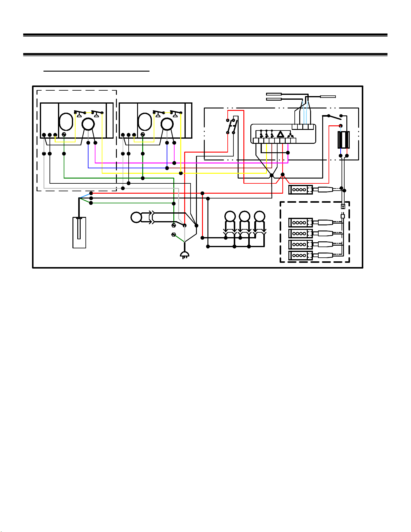
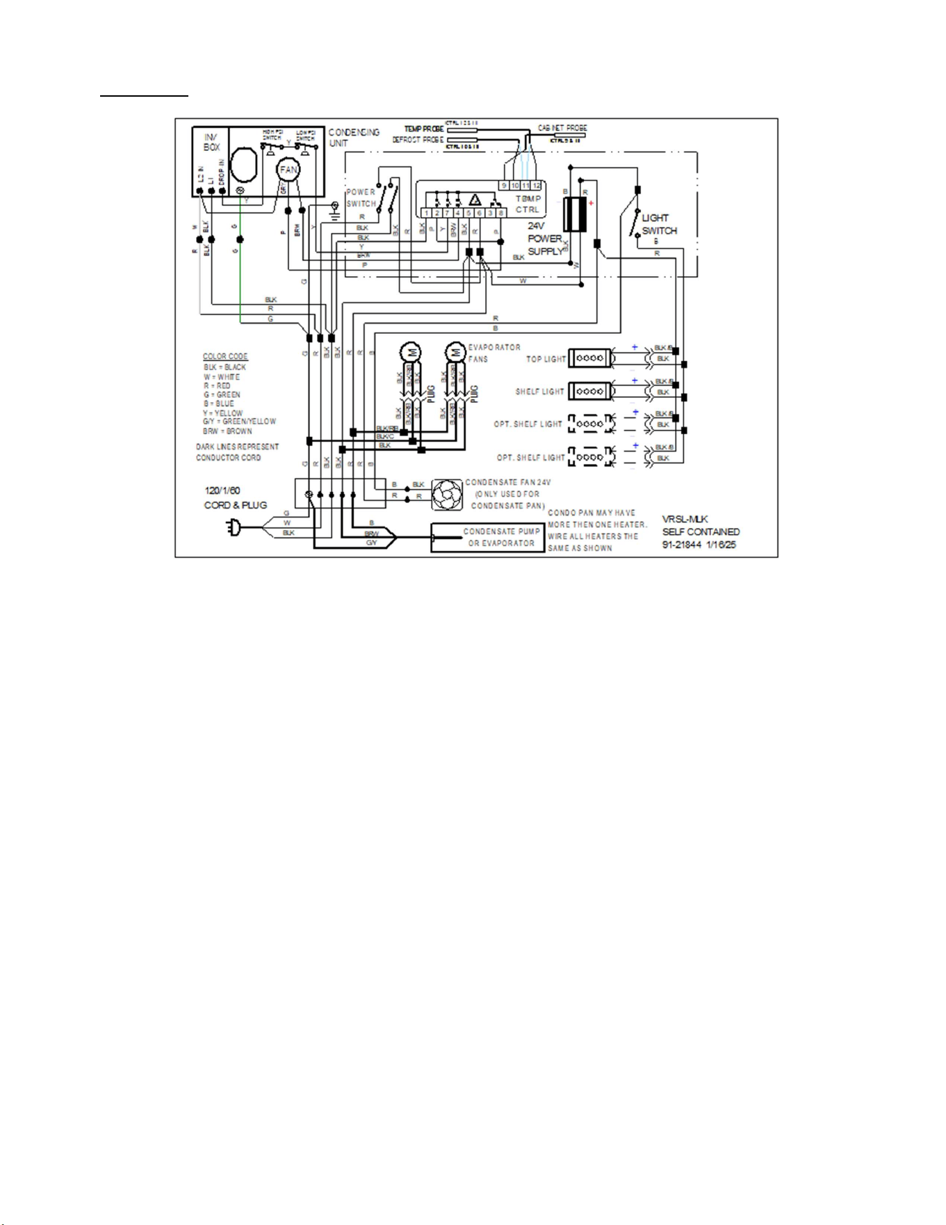
(18) WIRING DIAGRAM
18.1 VRSS SELF CONTAINED R290
VRSS &VRSL
SELF CONTAINED R290
91-21393-10 REV A
Y
POWER
SWITCH
LIGHT SWITCH
BLK
BLK
R
R
R
R
TOP LIGHT
R
BLK
B
BLK
R
R
G
W
BLK
W
G
EVAPORATOR FAN
(QTY MAY VARY)
24V POWER SUPPLY
M
PLUG
+
-
M
M
FAN
CONDENSING UNIT
BLK
W
R
BLK
BLK W/RIB
BRW
Y
BLK
BLK = BLACK
W = WHITE
R = RED
G = GREEN
BL = BLUE
Y = YELLOW
BRW = BROWN
P = PINK
ORG = ORANGE
GRY = GREY
BLK
G
BRW
P
OPTIONAL SHELF LIGHTS
QTY MAY VARY
CORD & PLUG
💧
CONDENSATE EVAPORATOR
(HEATER QTY MAY VARY)
OR OPTIONAL PUMP
BLK W/RIB
BLK
W/RIB
W/RIB
W/RIB
BLK
BLK
BLK
P
BLK
TEMP PROBE
DEFROST PROBE
(CTRL 9 & 11)
(CTRL 10 & 11)
(CTRL 12 & 11)
TEMP PROBE
DEFROST PROBE
(CTRL 9 & 11)
(CTRL 10 & 11)
(CTRL 12 & 11)
TEMP PROBE
DEFROST PROBE
CABINET PROBE
(CTRL 9 & 11)
(CTRL 10 & 11)
(CTRL 12 & 11)
BLK
W
INV
BOX
BLK
L1
L2 IN
DROP-IN
BLK
W
BLK
R
Y
BLK
G
R
BLK
BLK
G
BL
GRY
W
LOW PSI
SWITCH
HIGH PSI
SWITCH
2ND CONDENSING UNIT 5' & 6' ONLY
W
W
G
BLK
G
BLK
BL
G
BLK
~
1 2 7 4 5 6 3 8
9 10 11 12
TEMP
CTRL
FAN
INV
BOX
L1
L2 IN
DROP-IN
GRY
W
LOW PSI
SWITCH
HIGH PSI
SWITCH
Y
BASE FAN
WHEN USED
P
M
W/RIB
BLK
Y
BL
E3980 VISION R290
48
18.2 VRSS REMOTE
TEMP PROBE
DEFROST PROBE
POWER
SWITCH
LIGHT
SWITCH
BLK
R
R
R
R
TOP LIGHT
R
BLK
SHELF LIGHT
B
R
BLK
G
24V POWER
SUPPLY
COLOR CODE
M
PLUG
SHELF LIGHT
SHELF LIGHT
+
-
SHELF LIGHT
M
BLK
W
R
BLK
BLK W/RIB
Y
BLK = BLACK
W = WHITE
R = RED
G = GREEN
B = BLUE
Y = YELLOW
BRW = BROWN
P = PINK
ORG = ORANGE
BLK
OPTIONAL, QTY VARIES
💧
BLK W/RIB
BLK
W/RIB
W/RIB
BLK
BLK
FAN
4 5
RELAY
M
REMOTE
COMPRESSOR
HI/LO PRESS SW
Y
Y
OPTIONAL REMOTE
MOUNTED & WIRED
COMPONENTS
ALL FIELD WIRED
SEPARATE
POWER SUPPLY
PRESSURE
CONTROL
REMOTE
CABINET PROBE
(CTRL 9 & 11)
(CTRL 10 & 11)
(CTRL 12 & 11)
TEMP PROBE
DEFROST PROBE
LIGHT
SWITCH
BLK
BLK
R
G
R
R
R
TOP LIGHT
R
BLK
SHELF LIGHT
B
R
BLK
G
24V POWER
SUPPLY
COLOR CODE
M
PLUG
SHELF LIGHT
SHELF LIGHT
+
-
SHELF LIGHT
M
BLK
W
R
BLK
BLK W/RIB
BLK = BLACK
W = WHITE
R = RED
G = GREEN
B = BLUE
Y = YELLOW
BRW = BROWN
P = PINK
ORG = ORANGE
BLK
OPTIONAL, QTY VARIES
💧
BLK W/RIB
BLK
W/RIB
W/RIB
BLK
BLK
FAN
4 5
RELAY
M
REMOTE
COMPRESSOR
HI/LO PRESS SW
Y
Y
OPTIONAL REMOTE
MOUNTED & WIRED
COMPONENTS
ALL FIELD WIRED
SEPARATE
POWER SUPPLY
PRESSURE
CONTROL
REMOTE
CABINET PROBE
(CTRL 9 & 11)
(CTRL 10 & 11)
(CTRL 12 & 11)
TEMP PROBE
DEFROST PROBE
LIGHT
SWITCH
BLK
BLK
R
R
R
R
TOP LIGHT
R
BLK
SHELF LIGHT
B
R
R
BLK
G
EVAPORATOR FAN(S)
(QTY VARIES BETWEEN MODELS)
24V POWER
SUPPLY
COLOR CODE
M
PLUG
SHELF LIGHT
SHELF LIGHT
+
-
SHELF LIGHT
M
BLK
W
R
BLK
BLK W/RIB
BLK = BLACK
W = WHITE
R = RED
G = GREEN
B = BLUE
Y = YELLOW
BRW = BROWN
P = PINK
ORG = ORANGE
BLK
OPTIONAL
OPTIONAL, QTY VARIES
💧
CONDENSATE EVAPORATOR
OR PUMP
BLK W/RIB
BLK
W/RIB
W/RIB
BLK
BLK
FIELD WIRE
CONNECTION
FAN
4 5
RELAY
M
REMOTE
COMPRESSOR
HI/LO PRESS SW
Y
Y
OPTIONAL REMOTE
MOUNTED & WIRED
COMPONENTS
ALL FIELD WIRED
SEPARATE
POWER SUPPLY
PRESSURE
CONTROL
REMOTE
R
CABINET PROBE
(CTRL 9 & 11)
(CTRL 10 & 11)
(CTRL 12 & 11)
M
W/RIB
OPTIONAL
BASE EXHAUST FAN FOR REMOTE
W/FIELD INSTALL CONDENSATE PAN
EEV
5
4
3
2
1
TEMP PROBE
(EVAP OUTLET)
PRESS.
TRANS.
Blk
RedYelOrg
RSV-
Blue
GrnBlk
TEMP 3
Red TEMP 2TEMP 1
RIBBON
CABLE
LID PCB
BASE
PCB
M
3=NO
4=NC
5=CMN
EEV CON
TRO
L
S
~
1 2 7 4 5 6 3 8
9
10 11 12
TEMP
CTRL
BLK
BRW
BRW
BLK
Y
BLK
BLK
BLK
BLK
BLK
BLK
R
R
R
R
R
BLK
Y
Y
BRW
BRW
JUMPER 1 TO 5
VRSS REMOTE
91-21410-1 6/10/24
LLS
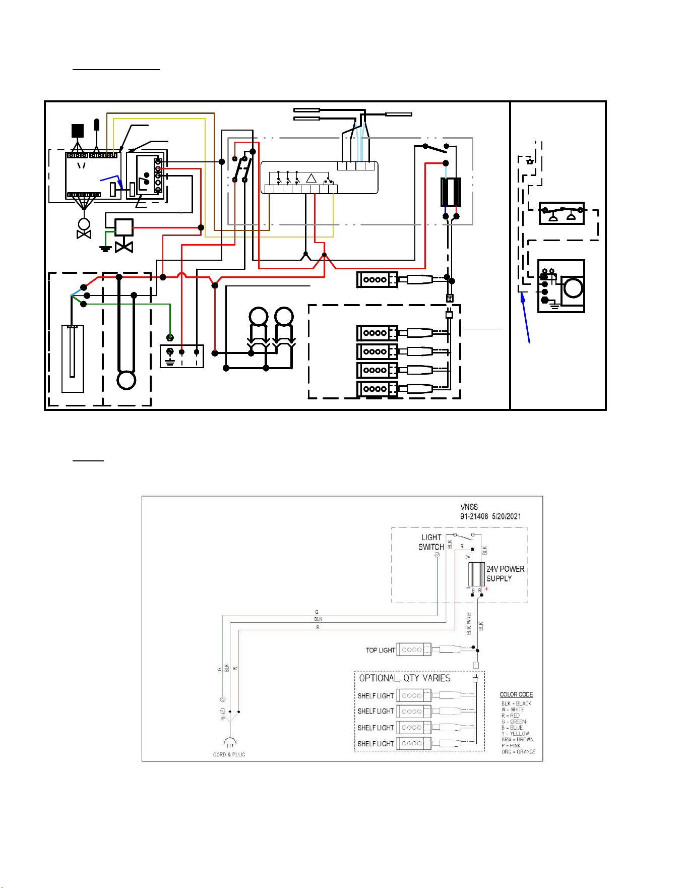
18.3 VNSS
E3980 VISION R290
49
18.4 VRSL-MLK
E3980 VISION R290
50
(19) SERVICE PARTS
QTY QTY QTY QTY QTY QTY QTY QTY QTY QTY QTY
2478 3683-MLK 3678 4878 6078 7278 2460 3660 4860 6060 7260
POWER CORD, 120V DRY (ALL VNSS UNITS)
43-20569
1 1 1 1 1 1 1 1 1 1 1
POWER CORD, 120V REFR NEMA 5-15 43-20569
1 1 --- --- --- --- 1 --- --- ---
POWER CORD, 240V REFR NEMA 6-15 43-20949
--- --- --- 1 --- --- --- --- 1 --- ---
POWER CORD, 240V REFR NEMA 6-20 43-19457
--- --- --- --- 1 1 --- --- --- 1 1
TEMP. CONT. 120V (NON-REVERSING FAN) 32-21341-27
--- 1 1 --- --- --- --- 1 --- --- ---
TEMP. CONT. 120V REMOTE 32-21341-17R
--- 1 1 --- --- --- --- 1 --- --- ---
TEMP. CONT. 120V (REVERSING FAN) 32-21341-28
--- 1 1 --- --- --- --- 1 --- --- ---
TEMP. CONT. 240V(NON-REVERSING FAN) 32-21342-27
--- --- --- 1 1 1 --- --- 1 1 1
TEMP. CONT. 240V REMOTE (AFTER 7/1/24) 32-21342-17R
--- --- --- 1 1 1 --- --- 1 1 1
TEMP. CONT. 240V (REVERSING FAN) 32-21342-28
--- --- --- 1 1 1 --- --- 1 1 1
TEMPERATURE PROBE 10' 32-19094
--- 3 3 2 2 3 --- 3 2 2 3
TEMPERATURE PROBE 20' 32-19866
--- --- --- 1 1 --- --- --- 1 1 ---
SWITCH,ROCKER POWER 22A 41-18186
--- 1 1 1 1 1 --- 1 1 1 1
SWITCH,ROCKER LIGHT22A 41-1066
1 1 1 1 1 1 1 1 1 1 1
HARNESS,SHELF LIGHTS 43-21333
1 1 1 1 1 1 --- 1 1 1 1
POWER SUPPLY 24V 100W 39-20555
1 1 1 1 1 1 --- 1 1 1 1
TOP LIGHT 42-20871-20C35
1 --- --- --- --- --- 1 --- --- --- ---
42-20871-30C35
--- 1 1 --- --- --- --- 1 --- --- ---
42-20871-42C35
--- --- --- 1 --- --- --- --- 1 --- ---
42-20871-54C35
--- --- --- --- 1 --- --- --- --- 1 ---
42-20871-66C35
--- --- --- --- --- 1 --- --- --- --- 1
SHELF LIGHTS 42-20871-20C35
4 --- --- --- --- --- 2 --- --- --- ---
42-20871-25C35
--- 4 4 --- --- --- --- 2 --- --- ---
42-20871-38C35
--- --- --- 4 --- --- --- --- 2 --- ---
42-20871-54C35
--- --- --- --- 4 --- --- --- --- 2 ---
42-20871-66C35
--- --- --- --- --- 4 --- --- --- --- 2
TAPE,LED LIGHT,DOUBLE SIDED
(QTY PER LED)
90-20985
40in
(.030
ROL)
49in
(.038 ROL)
49in
(.038
ROL)
70in
(.054
ROL)
102in
(.079
ROL)
126in
(0.098
ROL)
49in
(.038
ROL)
49in
(.038
ROL)
70in
(.054
ROL)
102in
(.079
ROL)
126in
(0.098
ROL)
QTY QTY QTY QTY QTY QTY QTY QTY QTY QTY QTY
2478 3683-MLK 3678 4878 6078 7278 2460 3660 4860 6060 7260
FAN MOTOR, BLADE, CORD, AND VENTURI VRSS 41-21237-14
--- --- --- --- --- --- --- 2 2 3 3
FAN MOTOR, BLADE, CORD, AND VENTURI VRSS 41-21237-16
--- 2 2 2 3 3 --- --- --- --- ---
FAN MOTOR, BLADE, CORD, AND VENTURI VRSL 41-21237-12
--- --- --- --- --- --- --- 2 --- 3 ---
FAN MOTOR, BLADE, CORD, AND VENTURI VRSL 41-21237-14
--- 2 2 --- 3 --- --- --- 2 --- 3
FAN MOTOR, BLADE, CORD, AND VENTURI VRSL 41-21237-16
--- --- --- 2 --- 3 --- --- --- --- ---
BASE FAN MOTOR, BLADE, CORD, AND VENTURI VRSS/VRSL 41-21237-20
--- --- 1 1 1 1 --- 1 1 1 1
FAN HARNESS 43-21501
--- 1 1 1 1 2 --- 1 1 2 2
TXV (SELF CONTAINED) 32-21749
--- --- --- 1 --- --- --- --- 1 --- ---
TXV (SELF CONTAINED) 32-21750
--- 1 1 2 2 --- 1 --- 2 2
EEV (REMOTE) 32-21228
--- 1 1 --- --- --- --- 1 --- --- ---
EEV (REMOTE) 32-21226
--- --- --- 1 1 1 --- --- 1 1 1
EEV PRESSURE TRANSDUCER (REMOTE) 32-21225
--- 1 1 1 1 1 --- 1 1 1 1
COIL,EVAPORATOR,36IN 33-21288-21
--- 1 1 --- --- --- --- 1 --- --- ---
COIL,EVAPORATOR,48IN 33-21288-22
--- --- --- 1 --- --- --- --- 1 --- ---
COIL,EVAPORATOR,60IN 33-21288-43
--- --- --- --- 1 --- --- --- --- 1 ---
COIL,EVAPORATOR,72IN 33-21288-44
--- --- --- --- --- 1 --- --- --- --- 1
COIL,EVAPORATOR,36IN REMOTE 33-21288-1
--- 1 1 --- --- --- --- 1 --- --- ---
COIL,EVAPORATOR,48IN REMOTE 33-21288-2
--- --- --- 1 --- --- --- --- 1 --- ---
COIL,EVAPORATOR,60IN REMOTE 33-21288-3
--- --- --- --- 1 --- --- --- --- 1 ---
COIL,EVAPORATOR,72IN REMOTE 33-21288-4
--- --- --- --- --- 1 --- --- --- --- 1
FILTER DRIER (REPLACEMENT) 32-12391
--- 1 1 1 1 1 --- 1 1 1 1
COMPRESSOR 30-21754-COMP
--- 1 1 --- 2 2 --- 1 --- 2 2
COMPRESSOR 30-21766-COMP
--- --- --- 1 --- --- --- --- 1 --- ---
CONDENSING UNIT 30-21754
--- 1 1 --- --- --- --- 1 --- --- ---
CONDENSING UNIT 30-21766
--- --- --- 1 --- --- --- --- 1 --- ---
CONDENSATE HEATER 600W 120V
40-19331 --- 1 1 --- --- --- --- 1 --- --- ---
CONDENSATE HEATER 600W 230V
40-19392 --- --- --- 1 1 1 --- --- 1 1 1
ELECTRICAL COMPONENTS
PART#
REFRIGERATION
PART#

E3980 VISION R290
51
E3980 VISION R290
52
QTY QTY QTY QTY QTY QTY QTY QTY QTY QTY QTY
2478
3683-MLK
3678 4878 6078 7278 2460 3660 4860 6060 7260
LEG LEVELER,1/2-13 X 2.5 65-21273
4
4 4 4 4 4 4 4 4 4 4
AIR DIFFUSER, 36IN W11823-1
---
1 1 --- --- --- --- 1 --- --- ---
AIR DIFFUSER, 48IN W11823-2
---
--- --- 1 --- --- --- --- 1 --- ---
AIR DIFFUSER, 60IN W11823-3
---
--- --- --- 2 --- --- --- --- 2 ---
AIR DIFFUSER, 72IN W11823-4
---
--- --- --- --- 2 --- --- --- --- 2
PVC TUB FITTING FOR COPPER AND ELECTRICAL 84-21557
---
2 2 2 2 2 --- 2 2 2 2
FITTING NUT 84-21558
---
2 2 2 2 2 --- 2 2 2 2
FITTING GASKET 84-21559
---
2 2 2 2 2 --- 2 2 2 2
SPRAY FOAM SEALANT 22-21574
---
1 1 1 1 1 --- 1 1 1 1
DRAIN ASSY,TUBE,RAID REAR AIR IN/OUT SA6228-1
---
--- --- --- 2 --- --- --- --- 2 ---
DRAIN ASSY,TUBE,REMOTE W/PUMP
---
1 1 1 --- --- --- 1 1 --- ---
THERMOPLASTIC DRAIN
84-70225
---
1 1 1 2 2 --- 1 1 2 2
DRAIN WASHER
M-6229
---
1 1 1 2 2 --- 1 1 2 2
AIR DEFLECTOR VRSS 78" TALL 51-21305-1
---
1 1 --- --- --- --- --- --- --- ---
51-21305-2
---
--- --- 1 --- --- --- --- --- --- ---
51-21305-3
---
--- --- --- 1 --- --- --- --- --- ---
51-21305-4
---
--- --- --- --- 1 --- --- --- --- ---
AIR DEFLECTOR VRSS 60" & VRSL ALL 51-21305-11
---
1 1 --- --- --- --- 1 --- --- ---
51-21305-12
---
--- --- 1 --- --- --- --- 1 --- ---
51-21305-13
---
--- --- --- 1 --- --- --- --- 1 ---
51-21305-14
---
--- --- --- --- 1 --- --- --- --- 1
AIR DEFLECTOR FOR CASES W/ROLL COVER
VRSS
51-21305-5
---
1 1 --- --- --- --- --- --- --- ---
51-21305-6
---
--- --- 1 --- --- --- --- --- --- ---
51-21305-7
---
--- --- --- 1 --- --- --- --- --- ---
51-21305-8
---
--- --- --- --- 1 --- --- --- --- ---
51-21305-15
---
--- --- --- --- --- --- 1 --- --- ---
51-21305-16
---
--- --- --- --- --- --- --- 1 --- ---
51-21305-17
---
--- --- --- --- --- --- --- --- 1 ---
51-21305-18
---
--- --- --- --- --- --- --- --- --- 1
AIR DEFLECTOR FOR CASES W/ROLL COVER
VRSL
51-21305-29
---
1 1 --- --- --- --- 1 --- --- ---
51-21305-30
---
--- --- 1 --- --- --- --- 1 --- ---
51-21305-31
---
--- --- --- 1 --- --- --- --- 1 ---
51-21305-32
---
--- --- --- --- 1 --- --- --- --- 1
AIR DEFLECTOR SLIDE-IN 60" TALL CASES ONLY
VRSS
51-21305-21
---
--- --- --- --- --- --- 1 --- --- ---
51-21305-22
---
--- --- --- --- --- --- --- 1 --- ---
51-21305-23
---
--- --- --- --- --- --- --- --- 1 ---
51-21305-24
---
--- --- --- --- --- --- --- --- --- 1
AIR DEFLECTOR SLIDE-IN W/ROLL COVER 60"
VRSS
51-21305-25
---
--- --- --- --- --- --- 1 --- --- ---
51-21305-26
---
--- --- --- --- --- --- --- 1 --- ---
51-21305-27
---
--- --- --- --- --- --- --- --- 1 ---
51-21305-28
---
--- --- --- --- --- --- --- --- --- 1
NIGHT CURTAIN 65-19300
---
1 1 --- --- 2 --- 1 --- --- 2
65-21374
---
--- --- 1 --- --- --- --- 1 --- ---
65-19458
---
--- --- --- 2 --- --- --- --- 2 ---
SECURITY COVER (OPTIONAL) KIT
VRSS
800-9611-BK
---
--- --- --- --- --- --- 1 --- --- ---
801-9611-BK
---
1 1 --- --- --- --- --- --- --- ---
802-9611-BK
---
--- --- --- --- --- --- --- 1 --- ---
803-9611-BK
---
--- --- 1 --- --- --- --- --- --- ---
804-9611-BK
---
--- --- --- --- --- --- --- --- 1 ---
805-9611-BK
---
--- --- --- 1 --- --- --- --- --- ---
806-9611-BK
---
--- --- --- --- --- --- --- --- --- 1
807-9611-BK
---
--- --- --- --- 1 --- --- --- --- ---
SECURITY COVER (OPTIONAL) KIT
VRSL
810-9611-EXTB
---
--- --- --- --- --- --- 1 --- --- ---
811-9611-EXTB
---
1 1 --- --- --- --- --- --- --- ---
812-9611-EXTB
---
--- --- --- --- --- --- --- 1 --- ---
813-9611-EXTB
---
--- --- 1 --- --- --- --- --- --- ---
814-9611-EXTB
---
--- --- --- --- --- --- --- --- 1 ---
815-9611-EXTB
---
--- --- --- 1 --- --- --- --- --- ---
816-9611-EXTB
---
--- --- --- --- --- --- --- --- --- 1
817-9611-EXTB
---
--- --- --- --- 1 --- --- --- --- ---
MISC COMPONENTS
PART#
E3980 VISION R290
53
QTY QTY QTY QTY QTY QTY QTY QTY QTY QTY QTY
2478
3683-MLK
3678 4878 6078 7278 2460 3660 4860 6060 7260
BASE FRONT GRILLE ASSEMBLY VISION
VRSS
SA6018-11B
--- 1 1 --- --- --- --- 1 --- --- ---
SA6018-12B
--- --- --- 1 --- --- --- --- 1 --- ---
SA6018-13B
--- --- --- --- 1 --- --- --- --- 1 ---
SA6018-14B
--- --- --- --- --- 1 --- --- --- --- 1
BASE FRONT GRILLE ASSEMBLY VISION VRSL SA6183-1B
--- 1 1 --- --- --- --- 1 --- --- ---
SA6183-2B
--- --- --- 1 --- --- --- --- 1 --- ---
SA6183-3B
--- --- --- --- 1 --- --- --- --- 1 ---
SA6183-4B
--- --- --- --- --- 1 --- --- --- --- 1
BASE FRONT PANEL
VRSL-MLK
M21963-1B
--- 1 --- --- --- --- --- --- --- --- ---
BASE FRONT PANEL
DRY
SA6294-B
1 --- --- --- --- --- 1 --- --- --- ---
SA6294-1B
--- 1 1 --- --- --- --- 1 --- --- ---
SA6294-2B
--- --- --- 1 --- --- --- --- 1 --- ---
SA6294-3B --- --- --- --- 1 --- --- --- --- 1 ---
SA6294-4B
--- --- --- --- --- 1 --- --- --- --- 1
BASE FRONT PANEL SLIDE-IN
VRSS
SA6294-1B
---
---
---
---
---
---
1
1
---
---
---
SA6294-2B --- --- --- --- --- --- --- --- 1 --- ---
SA6294-3B
---
---
---
---
---
---
---
---
---
1
---
SA6294-4B
---
---
---
---
---
---
---
---
---
---
1
DECAL, CAUTION ELECTRICAL SHOCK 91-12340 1 1 1 1 1 1 1 1 1 1 1
LOGO,FEDERAL 91-72523
1 1 1 1 1 1 1 1 1 1 1
QTY QTY QTY QTY QTY QTY QTY QTY QTY QTY QTY
2478
3683-MLK
3678 4878 6078 7278 2460 3660 4860 6060 7260
BOTTOM END PANEL BLACK LEFT
VRSS
68-21300-1LB
1 1 1 1 1 1 1 1 1 1 1
BOTTOM END PANEL BLACK RIGHT
VRSS
68-21300-1RB
1 1 1 1 1 1 1 1 1 1 1
BOTTOM END PANEL BLACK LEFT
VRSL
68-21713-1LB
1 1 1 1 1 1 1 1 1 1 1
BOTTOM END PANEL BLACK RIGHT
VRSL
68-21713-1RB
1 1 1 1 1 1 1 1 1 1 1
BOTTOM END PANEL BLACK LEFT
VRSL-MLK
68-21714-1LB
--- 1 --- --- --- --- --- --- --- --- ---
BOTTOM END PANEL BLACK RIGHT
VRSL-MLK
68-21714-1RB
--- 1 --- --- --- --- --- --- --- --- ---
GLASS END SQUARE BLACK LEFT VRSS 50-21330-1LB
1 1 1 1 1 1 --- --- --- --- ---
GLASS END SQUARE BLACK RIGHT
VRSS
50-21330-1RB
1 1 1 1 1 1 --- --- --- --- ---
GLASS END SQUARE BLACK LEFT
VRSS
50-21330-2LB
--- --- --- --- --- --- 1 1 1 1 1
GLASS END SQUARE BLACK RIGHT
VRSS
50-21330-2RB
--- --- --- --- --- --- 1 1 1 1 1
GLASS END CURVED BLACK LEFT
VRSS
50-21299-1LB
1 1 1 1 1 1 --- --- --- --- ---
GLASS END CURVED BLACK RIGHT
VRSS
50-21299-1RB
1 1 1 1 1 1 --- --- --- --- ---
GLASS END CURVED BLACK LEFT
VRSS
50-21299-2LB
--- --- --- --- --- --- 1 1 1 1 1
GLASS END CURVED BLACK RIGHT
VRSS
50-21299-2RB
--- --- --- --- --- --- 1 1 1 1 1
GLASS END SQUARE BLACK LEFT VRSL & VRSL-MLK 50-21714-1LB
1 1 1 1 1 1 --- --- --- --- ---
GLASS END SQUARE BLACK RIGHT
VRSL & VRSL-MLK
50-21714-1RB
1 1 1 1 1 1 --- --- --- --- ---
GLASS END SQUARE BLACK LEFT
VRSL
50-21714-2LB
--- --- --- --- --- --- 1 1 1 1 1
GLASS END SQUARE BLACK RIGHT VRSL
50-21714-2RB --- --- --- --- --- --- 1 1 1 1 1
ENDS COMPONENTS CONTINUED
PART#
PART#
MISC COMPONENTS CONTINUED
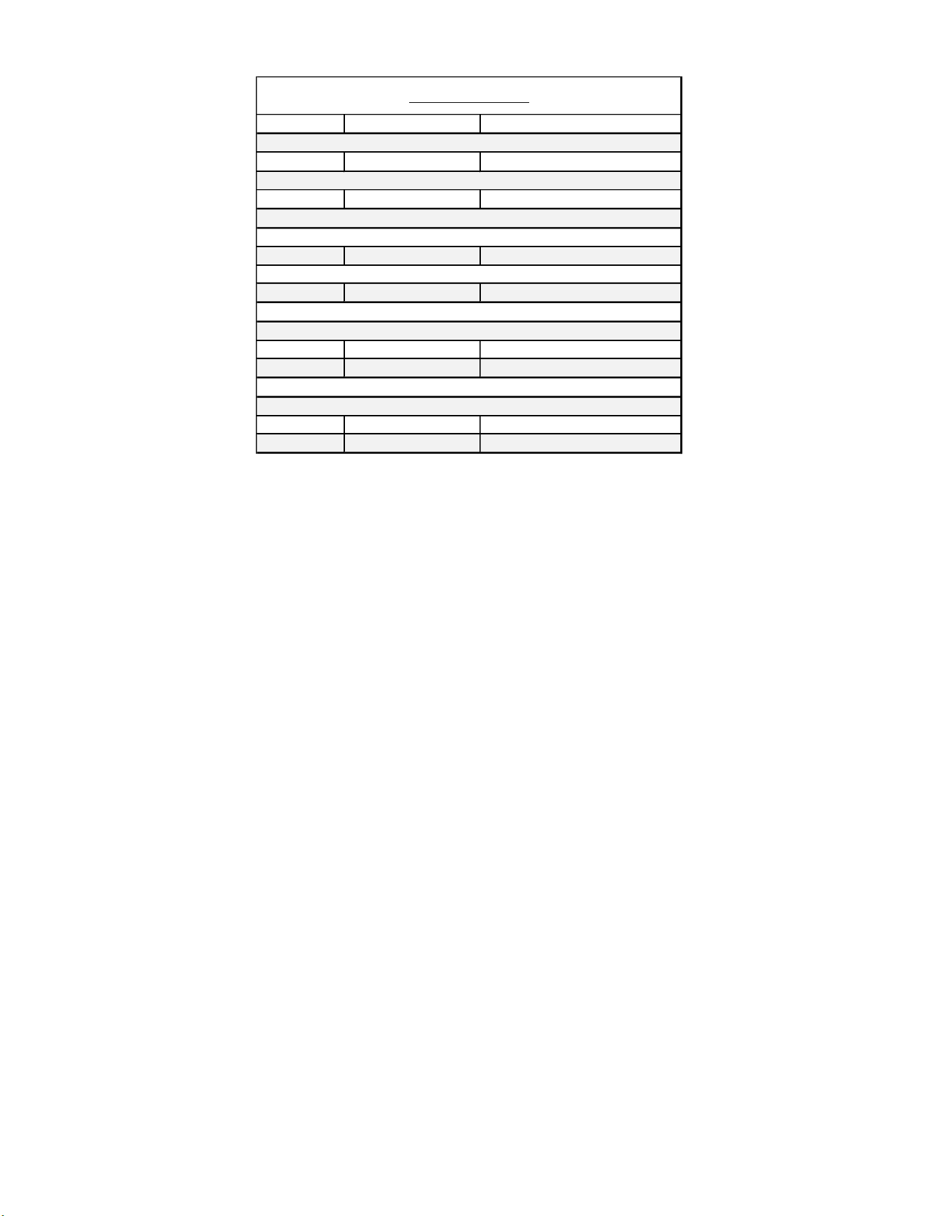
E3980 VISION R290
54
LEFT RIGHT
BLACK 50-21605-2B 50-21605-2B
50-21605-12LB 50-21605-12RB
BLACK 50-21619-2B 50-21619-2B
50-21619-12LB 50-21619-12RB
BLACK 68-21623-23L 68-21623-23R
WHITE 68-21623-26L 68-21623-26R
BLACK 68-21622-23L 68-21622-23R
WHITE 68-21622-26L 68-21622-26R
END PANELS SLIDE-IN
END GLASS PANELS SQUARE CLEAR
END GLASS PANELS CURVED CLEAR
END PANELS FOR SOLID END STRAIGHT PROFILE LAMINATED, 60IN HEIGHT
END GLASS PANELS SQUARE REFLECTIVE
END PANELS FOR SOLID END CURVED PROFILE LAMINATED, 60IN HEIGHT
END GLASS PANELS CURVED REFLECTIVE
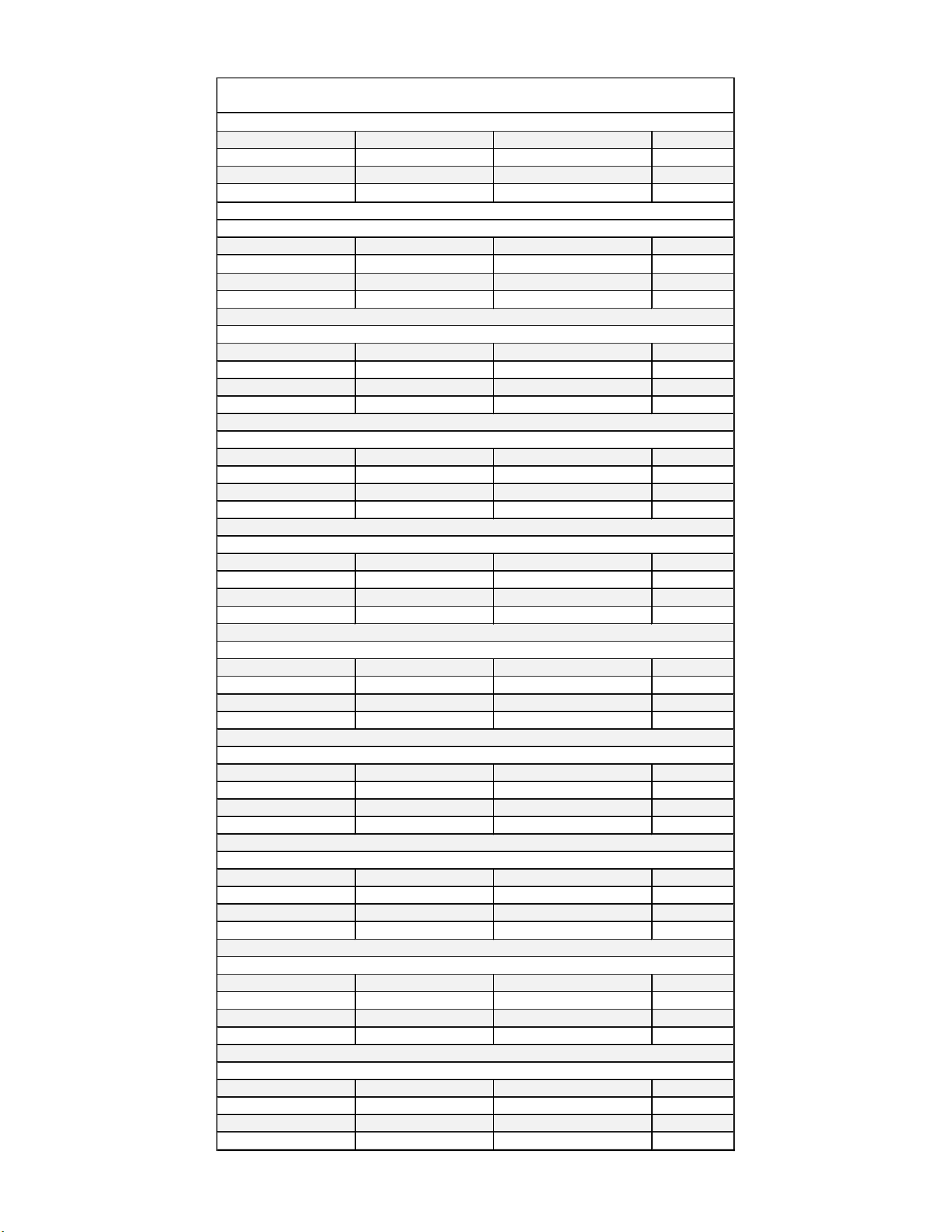
E3980 VISION R290
55
COLOR BRACKET (NEED TWO) SUPPORT SHELF
BLACK 67-21387-1B M21488-B M21487-10B
WHITE 67-21387-1W M21488-W M21487-10W
STAINLESS 67-21387-1S M21488-S M21487-10S
COLOR BRACKET (NEED TWO) SUPPORT SHELF
BLACK 67-21387-1B M21488-1B M21487-11B
WHITE 67-21387-1W M21488-1W M21487-11W
STAINLESS 67-21387-1S M21488-1S M21487-11S
COLOR BRACKET (NEED TWO) SUPPORT SHELF
BLACK 67-21387-1B M21488-2B M21487-12B
WHITE 67-21387-1W M21488-2W M21487-12W
STAINLESS 67-21387-1S M21488-2S M21487-12S
COLOR BRACKET (NEED TWO) SUPPORT SHELF
BLACK 67-21387-1B M21488-3B M21487-13B
WHITE 67-21387-1W M21488-3W M21487-13W
STAINLESS 67-21387-1S M21488-3S M21487-13S
COLOR BRACKET (NEED TWO) SUPPORT SHELF
BLACK 67-21387-1B M21488-4B M21487-14B
WHITE 67-21387-1W M21488-4W M21487-14W
STAINLESS 67-21387-1S M21488-4S M21487-14S
COLOR BRACKET (NEED TWO) SUPPORT SHELF
BLACK 67-21387-B M21488-B M21487-B
WHITE 67-21387-W M21488-W M21487-W
STAINLESS 67-21387-S M21488-S M21487-S
COLOR BRACKET (NEED TWO) SUPPORT SHELF
BLACK 67-21387-B M21488-1B M21487-1B
WHITE 67-21387-W M21488-1W M21487-1W
STAINLESS 67-21387-S M21488-1S M21487-1S
COLOR BRACKET (NEED TWO) SUPPORT SHELF
BLACK 67-21387-B M21488-2B M21487-2B
WHITE 67-21387-W M21488-2W M21487-2W
STAINLESS 67-21387-S M21488-2S M21487-2S
COLOR BRACKET (NEED TWO) SUPPORT SHELF
BLACK 67-21387-B M21488-3B M21487-3B
WHITE 67-21387-W M21488-3W M21487-3W
STAINLESS 67-21387-S M21488-3S M21487-3S
COLOR BRACKET (NEED TWO) SUPPORT SHELF
BLACK 67-21387-B M21488-4B M21487-4B
WHITE 67-21387-W M21488-4W M21487-4W
STAINLESS 67-21387-S M21488-4S M21487-4S
17IN DEEP SHELVES FOR BOTTOM TWO SHELVES OF 78IN TALL OR ANY 60IN TALL, 72IN LONG
17IN DEEP SHELVES FOR BOTTOM TWO SHELVES OF 78IN TALL OR ANY 60IN TALL, 60IN LONG
17IN DEEP SHELVES FOR BOTTOM TWO SHELVES OF 78IN TALL OR ANY 60IN TALL, 48IN LONG
17IN DEEP SHELVES FOR BOTTOM TWO SHELVES OF 78IN TALL OR ANY 60IN TALL, 36IN LONG
SHELF PARTS FOR 78IN, TOP 2-3 15IN DEEP SHELVES FOR 72IN LONG UNITS
SHELF PARTS FOR 78IN, TOP 2-3 15IN DEEP SHELVES FOR 60IN LONG UNITS
SHELF PARTS FOR 78IN, TOP 2-3 15IN DEEP SHELVES FOR 48IN LONG UNITS
METAL SHELVING
SHELF PARTS FOR 78IN, TOP 2-3 15IN DEEP SHELVES FOR 24IN LONG UNITS
17IN DEEP SHELVES FOR BOTTOM TWO SHELVES OF 78IN TALL OR ANY 60IN TALL, 24IN LONG
SHELF PARTS FOR 78IN, TOP 2-3 15IN DEEP SHELVES FOR 36IN LONG UNITS
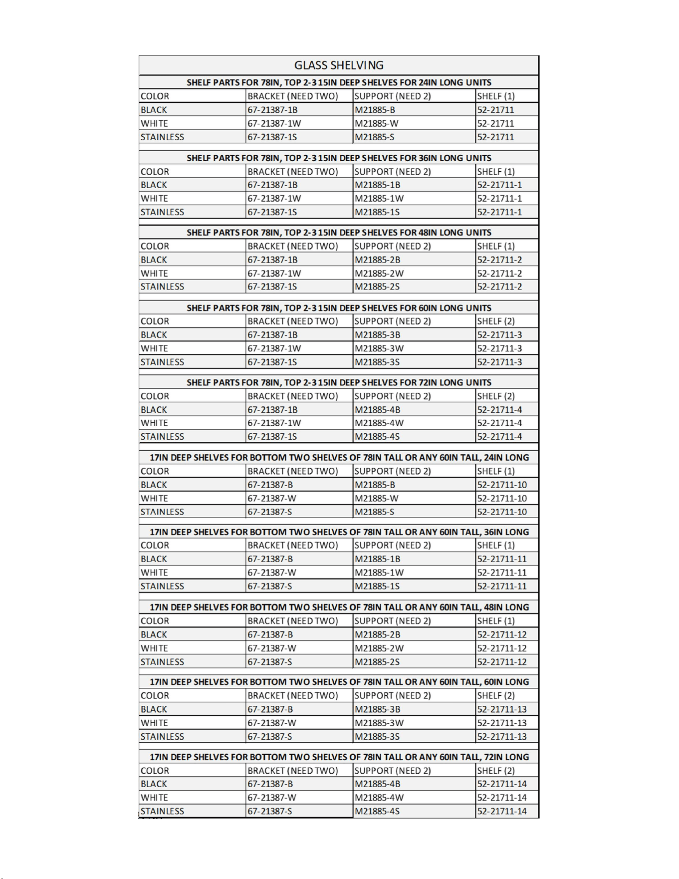
E3980 VISION R290
56
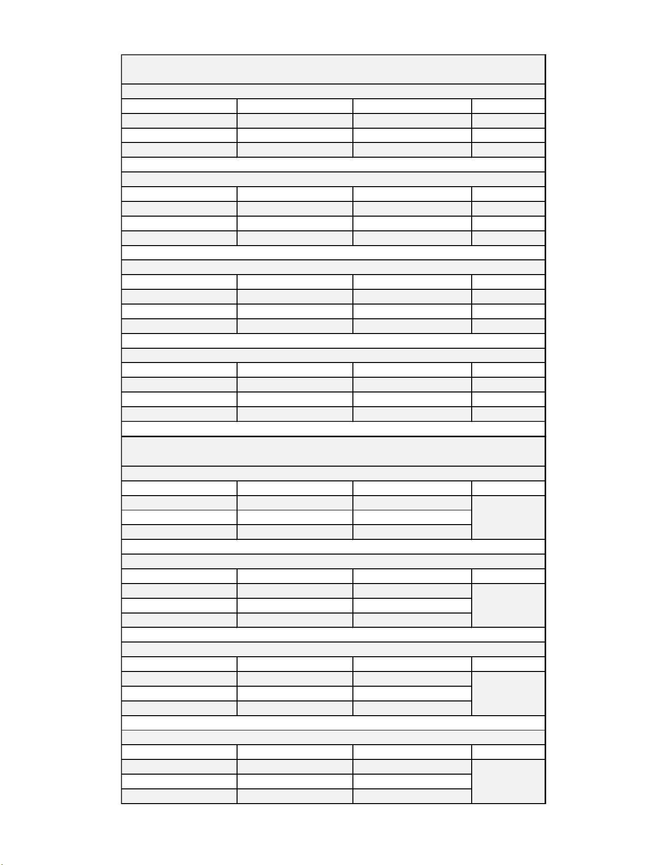
E3980 VISION R290
57
COLOR BRACKET (NEED TWO) SUPPORT SHELF
BLACK 67-21723-B M21488-1B M21487-16B
WHITE 67-21723-W M21488-1W M21487-16W
STAINLESS 67-21723-S M21488-1S M21487-16S
COLOR BRACKET (NEED TWO) SUPPORT SHELF
BLACK 67-21387-1B M21488-2B M21487-17B
WHITE 67-21387-1W M21488-2W M21487-17W
STAINLESS 67-21387-1S M21488-2S M21487-17S
COLOR BRACKET (NEED TWO) SUPPORT SHELF
BLACK 67-21387-1B M21488-3B M21487-18B
WHITE 67-21387-1W M21488-3W M21487-18W
STAINLESS 67-21387-1S M21488-3S M21487-18S
COLOR BRACKET (NEED TWO) SUPPORT SHELF
BLACK 67-21387-1B M21488-4B M21987-19B
WHITE 67-21387-1W M21488-4W M21987-19W
STAINLESS 67-21387-1S M21488-4S M21987-19S
COLOR BRACKET (NEED TWO) SUPPORT (NEED (2) SHELF
BLACK 67-21723-B M21488-1B
WHITE 67-21723-W M21488-1W
STAINLESS 67-21723-S M21488-1S
COLOR BRACKET (NEED TWO) SUPPORT (NEED (2) SHELF
BLACK 67-21387-1B M21488-2B
WHITE 67-21387-1W M21488-2W
STAINLESS 67-21387-1S M21488-2S
COLOR BRACKET (NEED TWO) SUPPORT (NEED (2) SHELF NEED (2)
BLACK 67-21387-1B M21488-3B
WHITE 67-21387-1W M21488-3W
STAINLESS 67-21387-1S M21488-3S
COLOR BRACKET (NEED TWO) SUPPORT (NEED (2) SHELF NEED (2)
BLACK 67-21387-1B M21488-4B
WHITE 67-21387-1W M21488-4W
STAINLESS 67-21387-1S M21488-4S
SHELF PARTS FOR 12.5"IN DEEP SHELVES FOR 36IN LONG UNITS
52-21711-21
52-21711-22
52-21711-23
52-21711-24
VRSL GLASS SHELVING
SHELF PARTS FOR 12.5 "IN DEEP SHELVES FOR 36IN LONG UNITS
SHELF PARTS FOR 12.5 "IN DEEP SHELVES FOR 36IN LONG UNITS
SHELF PARTS FOR 12.5"IN DEEP SHELVES FOR 36IN LONG UNITS
VRSL METAL SHELVING
SHELF PARTS FOR 12.5 "IN DEEP SHELVES FOR 36IN LONG UNITS
SHELF PARTS FOR 12.5"IN DEEP SHELVES FOR 36IN LONG UNITS
SHELF PARTS FOR 12.5"IN DEEP SHELVES FOR 36IN LONG UNITS
SHELF PARTS FOR 12.5"IN DEEP SHELVES FOR 36IN LONG UNITS
E3980 VISION R290
58
Description PART# QTY/CASE
LEG LEVELER ASSEMBLY SA4368-1 4
LEG LEVELER 65-21273 4
HOUSING SA4295 4
6" LEG ASSEMBLY SA4368-2 4
6" LEG 65-12886 4
SCREW, 1/4-20 75-10948 16
HOUSING SA4295 4
4" CASTER ASSEMBLY SA4368-3 4
4" CASTER 65-10675 4
SCREW, 1/4-20 75-10948 16
HOUSING SA4295 4
2.5" CASTER ASSEMBLY SA4368-20 4
2.5" CASTER 65-15185 4
SCREW, 1/4-20 75-10948 16
HOUSING SA4295 4
RECESSED CASTER ASSEMBLY SA4368-4 4
2.5" CASTER 65-17352 4
SCREW, 1/4-20 75-10948 16
HOUSING M15895-2 4
6" SEISMIC LEG ASSEMBLY SA4368-13 4
6" SEISMIC LEG 65-19069 4
SCREW, 1/4-20 75-10948 16
HOUSING SA4295 4
4
ADJUSTABLE CASTERS SLIDE-IN 65-21657 4
SCREW, 1/4-20 75-10948 64
INNER SLIDE HOUSING M21799 4
OUTER SLIDE HOUSING M21798 4
BRACE SLIDE HOUSING M21814 2
SLIDE -IN ADJUSTABLE CASTER ASSEMBLIES
LEGS AND CASTERS
E3980 VISION R290
59
LED Shelf Lights Kit#
VRSS/VNSS2460 828-9200-LEDK
VRSS/VNSS3660 800-9200-LEDK
VRSS/VNSS2478 829-9200-LEDK
VRSS/VNSS3678/VRSL-MLK 801-9200-LEDK
VRSS/VNSS4860 802-9200-LEDK
VRSS/VNSS4878 803-9200-LEDK
VRSS/VNSS6060 804-9200-LEDK
VRSS/VNSS6078 805-9200-LEDK
VRSS/VNSS7260 806-9200-LEDK
VRSS/VNSS7278 807-9200-LEDK
High Output Condensate Pan, Single Drain Units
Kit#
VRSS36 ONLY 800-9121-PANK
VRSS48 ONLY 802-9121-PANK
High Output Condensate Pan,
Dual
Drain Units
VRSS60 ONLY 804-9122-PANK
VRSS72 ONLY 806-9122-PANK
Kits
E3980 VISION R290
60
REV
CHANGE RECORD
APP’D
DATE
ECN#
-
INITIAL RELEASE SES 1/30/25
California Residents Only.
WARNING
This product can expose you to chemicals including chromium which is known to the State of California to
cause cancer and birth defects or other reproductive harm. For more information go to
www.P65Warnings.ca.gov
E3980 VISION R290
61
See also section 14.3
Cleaning Condenser Coil
Condenser Coil Inspection Sheet
When rating, 1 is good condition, 5 is poor condition
Unit Install Date:
Unit Serial Number:
Date
Initial
Dirt
(1 Like New -
5 Very Dirty)
Cleaned
Coil (Y/N)
Coil Fins
(1 Like New - 5
Highly Deformed)
Comments

E3980 VISION R290
62