1
IMPORTANT: READ THESE INSTRUCTIONS CAREFULLY BEFORE STARTING INSTALLATION OR USE.
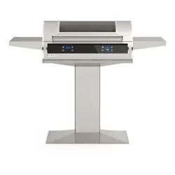
STAND-ALONE POST
Robert H. Peterson Co. • 14724 East Proctor Avenue • City of Industry, CA 91746
INSTALLATION INSTRUCTIONS
AND OWNER’S MANUAL
INSTALLER: Leave these instructions with consumer.
CONSUMER: Retain for future reference.
WARNING
Improper installation, adjustment, alteration,
service, or maintenance can cause injury or
property damage. For proper installation,
refer to the installation instructions. For
assistance or additional information,
consult a qualied professional service
technician or service agency.
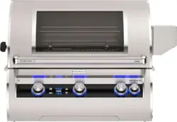
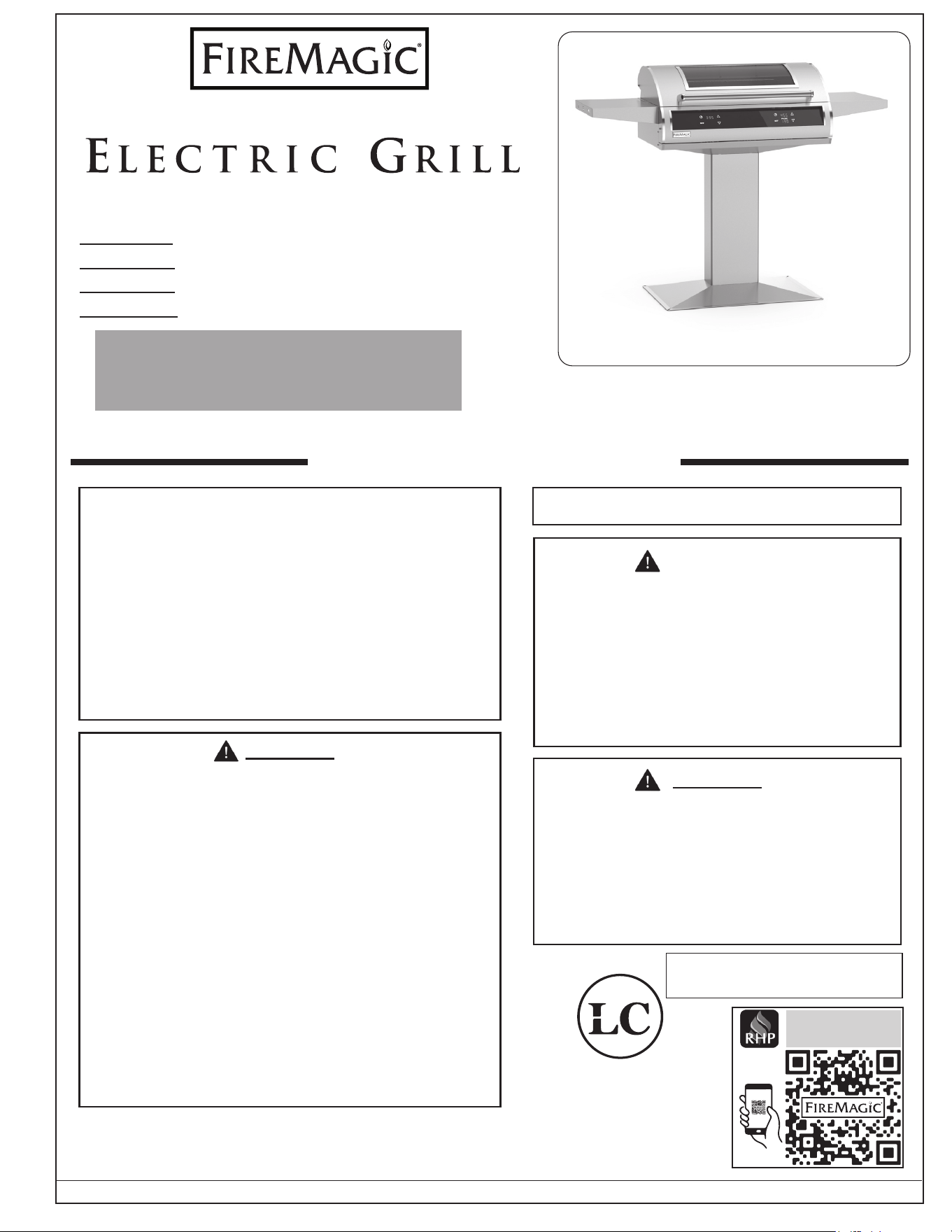
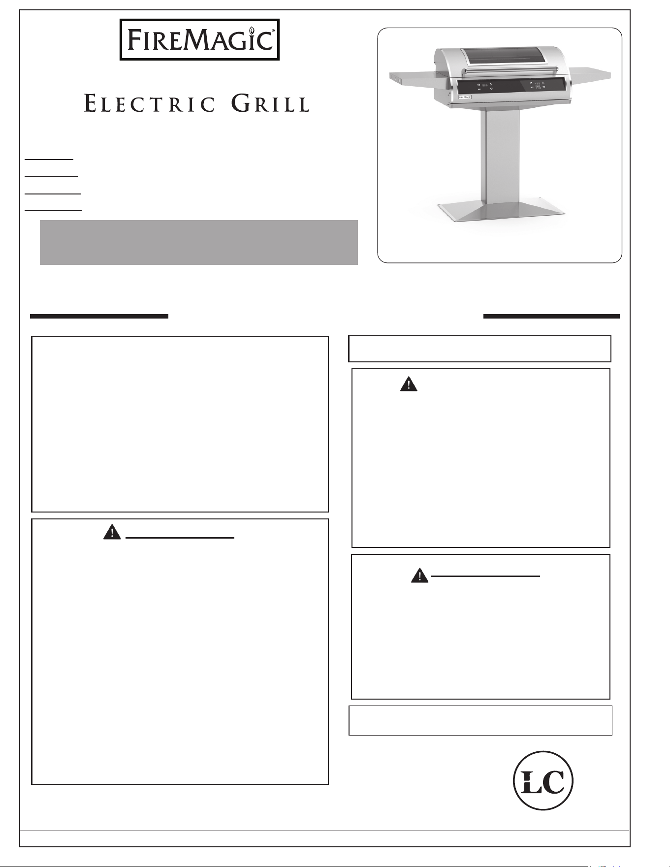
P6 Series w/ dual digital
controls and window shown
PLEASE READ AND FOLLOW
• Removing permanently axed rating warning
labels WILL void the warranty.
• Observe all local codes and ordinances when
installing this appliance. If no local codes are
applicable, wire unit in accordance with the
latest National Electrical Code, ANSI/NFPA
70, or the Canadian Electrical Code, CSA
C22.1, whichever is applicable.
WARNING
To minimize the risk of property damage
and/or personal injury, do not use a
flexible extension power-supply cord
unless it conforms with the specications
as listed in this manual (see IMPORTANT
SAFEGUARDS section).
NOT FOLLOWING THESE INSTRUCTIONS EXACTLY
WILL VOID THE MANUFACTURER'S WARRANTY.
WARNING
When connecting this appliance to a power
supply make sure that it is the same voltage
as the unit rating. Improper connection may
cause severe damage to the components or
decrease the performance of your Fire Magic
electric grill. A rating plate specifying voltage,
hertz, wattage, and amps is attached to the
rear of the unit and can be found in the MODEL
SPECIFICATIONS section. Also see the
IMPORTANT SAFEGUARDS section. To avoid
the risk of property damage and/or personal
injury, installation work and electrical wiring must
be performed by a qualied professional service
technician. This appliance must be installed in
accordance with this instruction.
SAFETY AND WARNING CODES
ONLY TO BE USED OUTDOORS
Cooking Grid U.S. Patent Nos.
D857,453 D862,984
SCAN
RHP CONNECT
APP
P6 Series: Patio Mount Standard Height (37")
AP Series: Patio Mount Accessible Height (32")
G6 Series: In-ground Mount Standard Height (37")
AG Series: In-ground Mount Accessible Height (32")
EL500s
Certied to:
ANSI/UL 1026
CSA C22.2 No. 60335-1
CSA C22.2 No. 60335-2-6
CSA C22.2 No. 60335-2-78
US
C
REV 1 - A - 2605071105
L-C2-744
2
Robert H. Peterson Co. • 14724 East Proctor Avenue • City of Industry, CA 91746
AVERTISSEMENT
L'installation inexacte, l'ajustement, le
changement, le service, ou l'entretien peuvent
causer des dommages ou des dégats
matériels. Pour l'installation appropriée,
référez-vous aux instructions d'installation.
Pour de l'aide ou des renseignements
supplémentaires, consulter une agence de
technicien de maintenance ou de service
professionnel qualié.
SVP LISEZ ET SUIVEZ
• L'enlèvement de manière permanente a apposé
des avertissements d'étiquette d'estimation
videra la garantie.
• Observez tous les codes et ordonnances
locaux en installant cet appareil. Si aucun code
local n'est applicable, unité de l selon le plus
défunt code électrique national, ANSI/NFPA 70,
ou le code électrique canadien, CSA C22.1,
celui qui est applicable.
AVERTISSEMENT
Pour réduire au minimum le risque de
dégats matériels et/ou de blessures,
n'employez pas une prolongation exible
puissance-fournissent la corde à moins
qu'elle se conforme aux caractéristiques
comme énuméré en ce manuel (voir la
section MISES EN GARDE IMPORTANT).
NON SUIVANT CES INSTRUCTIONS EXACTEMENT
VIDERONT LA GARANTIE DU FABRICANT.
AVERTISSEMENT
En reliant cet appareil à une alimentation d'énergie
assurez-vous que c'est la même tension que
l'estimation d'unité. Le raccordement inexact peut
endommager considérablement les composants
ou diminuer l'exécution de votre gril électrique de
Magic du feu. Une plaque signalétique spéciant
la tension, le hertz, la puissance et les ampères
est xée à l'arrière de l'appareil et se trouve
dans la section MODEL SPECIFICATIONS. Voir
aussi la section IMPORTANT SAFEGUARDS.
Pour éviter le risque de dommages aux biens et
/ ou des blessures, les travaux d'installation et
le câblage électrique doit être eectuée par un
technicien de service professionnel qualié. Cet
appareil doit être installé selon cette instruction.
SÛRETÉ ET CODES D'AVERTISSEMENT
À UTILISER UNIQUEMENT À L'EXTÉRIEUR
Grille de cuisson Numéros de brevets américains:
D857,453 D862,984
Série P6 avec doubles commandes
numériques et fenêtre achée
EL500s
Série P6: Hauteur Standard De Montage Sur Patio (37")
Série AP: Hauteur Accessible De Montage Sur Patio (32")
Série G6: Hauteur Standard De Montage En Terre (37")
Série AG: Hauteur Accessible De Montage En Terre (32")
Certié à :
ANSI/UL 1026
CSA C22.2 No. 60335-1
CSA C22.2 No. 60335-2-6
CSA C22.2 No. 60335-2-78
US
C
REV 1 - A - 2605071105
L-C2-744
IMPORTANT: LISEZ CES INSTRUCTIONS SOIGNEUSEMENT AVANT DE COMMENCER L'INSTALLATION OU L'UTILISATION.
INSTRUCTIONS D'INSTALLATION
ET MANUEL DU PROPRIÉTAIRE
INSTALLATEUR : Laissez ces instructions avec le consommateur. CONSOMMATEUR : Maintenez pour la future référence.
PIED AUTONOME

3
GETTING STARTED
GETTING STARTED
IMPORTANT SAFEGUARDS �����������������������������������������������������������������������������������������������������������������������������4
INSTALLATION REQUIREMENTS �����������������������������������������������������������������������������������������������������������������10
OVERHEAD CONSTRUCTION REQUIREMENTS ������������������������������������������������������������������������������������������������ 10
EXHAUST HOOD ������������������������������������������������������������������������������������������������������������������������������������������10
CLEARANCES ����������������������������������������������������������������������������������������������������������������������������������������������� 11
NOTES PAGE ����������������������������������������������������������������������������������������������������������������������������������������������������12
COOLING AIRFLOW �������������������������������������������������������������������������������������������������������������������������������������� 13
DIAGRAMMATICAL REPRESENTATIONS OF OUTDOOR AREAS �������������������������������������������������������������14
ELECTRICAL SAFETY ������������������������������������������������������������������������������������������������������������������������������������15
MODEL SPECIFICATIONS ������������������������������������������������������������������������������������������������������������������������������16
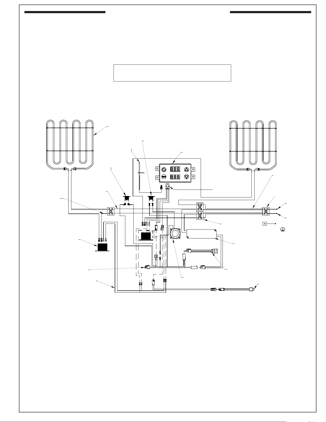
EL500s (single digital control models) WIRING DIAGRAM ������������������������������������������������������������������������������������� 19
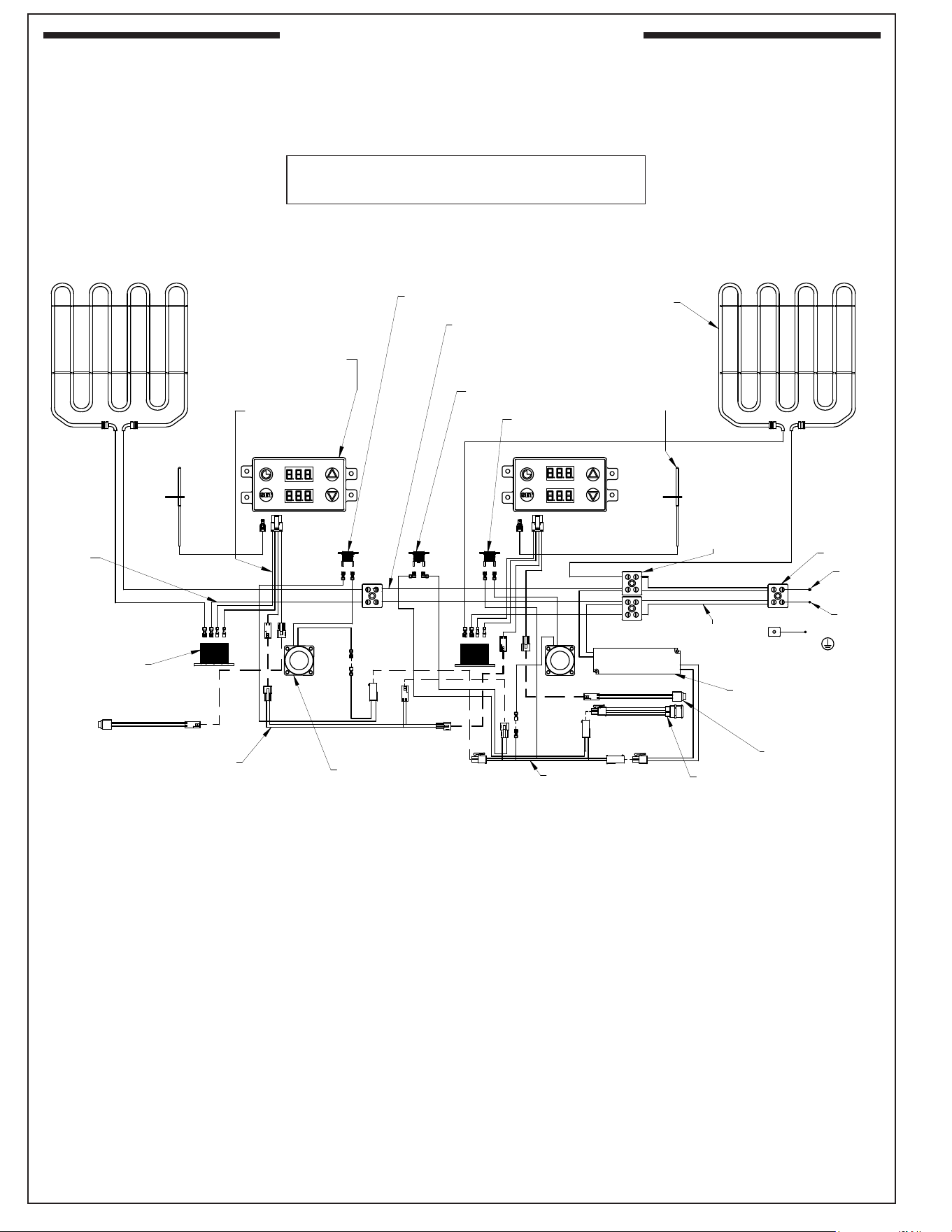
EL500s (dual digital control models) WIRING DIAGRAM ��������������������������������������������������������������������������������������� 20
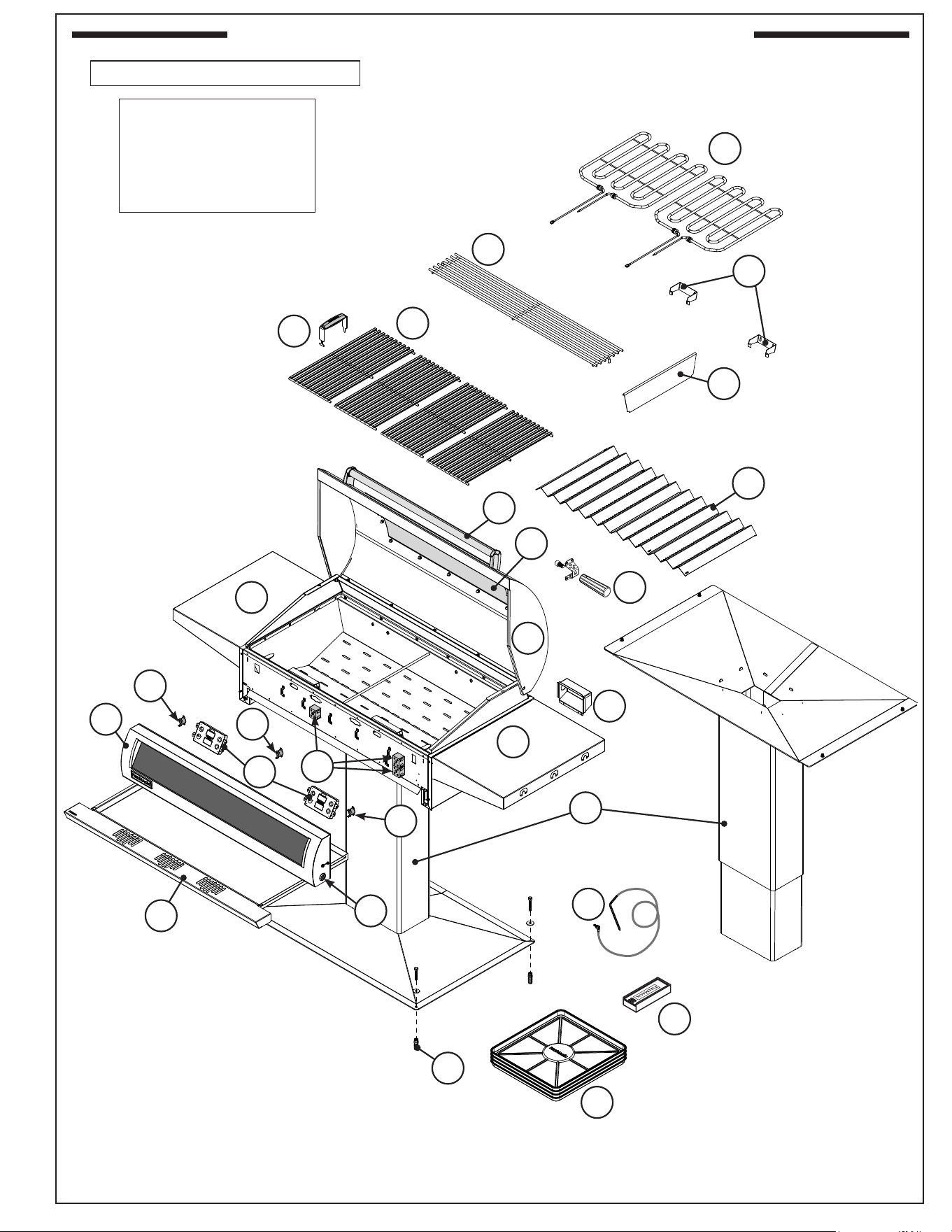
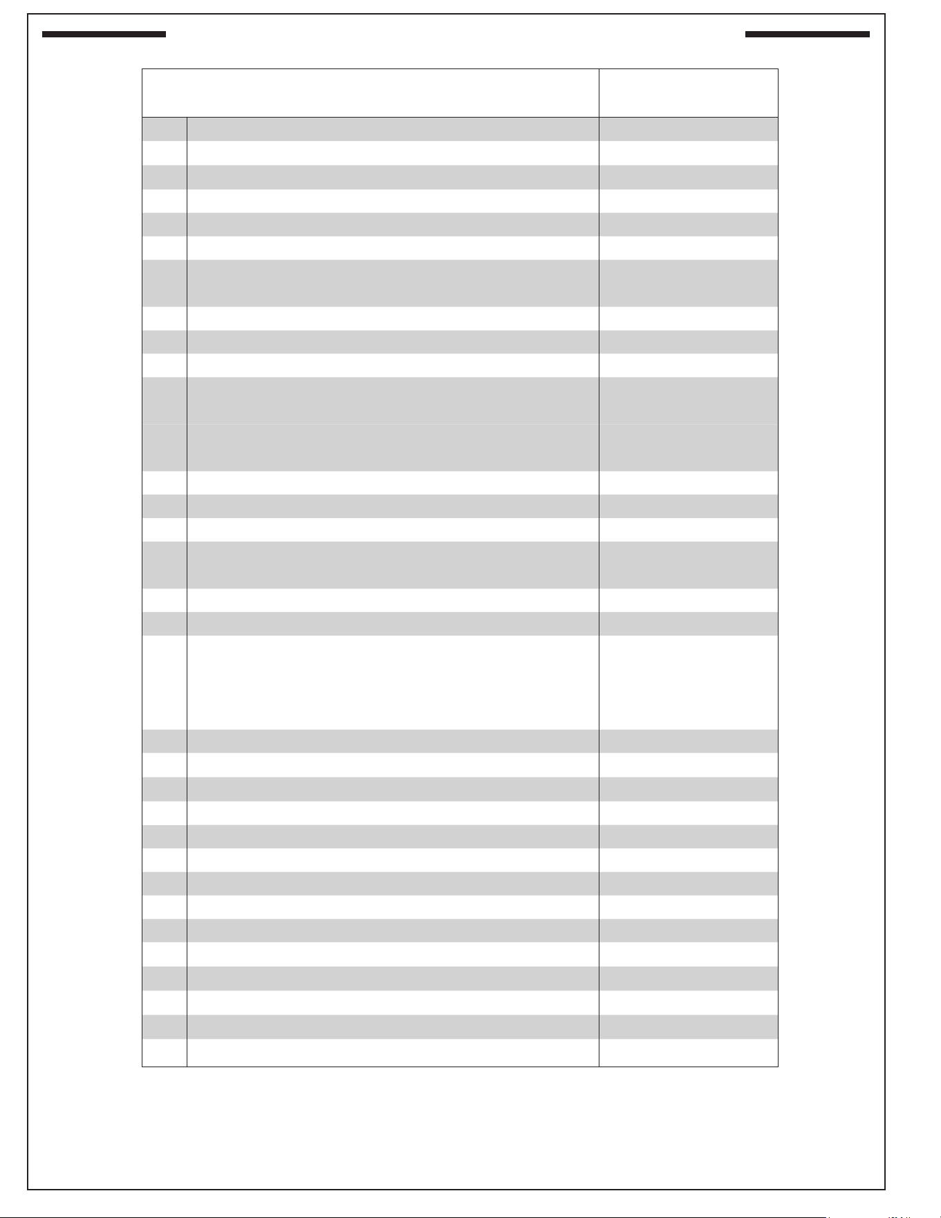
ELECTRIC GRILL REPLACEMENT PARTS LIST ������������������������������������������������������������������������������������������21
INSTALLATION
INSTALLATION PREPARATION ���������������������������������������������������������������������������������������������������������������������23
IMPORTANT SAFETY INFORMATION �����������������������������������������������������������������������������������������������������������23
LOCATION ��������������������������������������������������������������������������������������������������������������������������������������������������23
ELECTRICAL SETUP �������������������������������������������������������������������������������������������������������������������������������������25
PATIO MOUNT INSTALLATION ��������������������������������������������������������������������������������������������������������������������26
ABOVE-GROUND ELECTRICAL INSTALL METHOD ����������������������������������������������������������������������������������26
UNDERGROUND ELECTRICAL INSTALL METHOD �����������������������������������������������������������������������������������27
IN-GROUND POST INSTALLATION ���������������������������������������������������������������������������������������������������������������29
ABOVE GROUND ELECTRICAL INSTALL METHOD �����������������������������������������������������������������������������������29
UNDERGROUND ELECTRICAL INSTALL METHOD �����������������������������������������������������������������������������������31
COMMON INSTALLATION �����������������������������������������������������������������������������������������������������������������������������34
INSTALL VAPORIZER PANELS ������������������������������������������������������������������������������������������������������������������������� 34
INSTALL ZONE DIVIDER (dual control models) ��������������������������������������������������������������������������������������������������� 34
INSTALL COOKING GRIDS ����������������������������������������������������������������������������������������������������������������������������35
INSTALL WARMING RACK ������������������������������������������������������������������������������������������������������������������������������ 35
OPERATION TEST �������������������������������������������������������������������������������������������������������������������������������������������� 36
INSTALL DRIP TRAY ��������������������������������������������������������������������������������������������������������������������������������������36
INSTALL RIGID SHELVES ������������������������������������������������������������������������������������������������������������������������������� 36
INSTALL SIDE HANDLE KIT (AP Series Only)�����������������������������������������������������������������������������������������������������36
USE, CARE & SERVICE
USING THE GRILL ������������������������������������������������������������������������������������������������������������������������������������������� 37
USING THE ELECTRIC GRILL �����������������������������������������������������������������������������������������������������������������������37
DIGITAL THERMOMETER / THERMOSTAT ��������������������������������������������������������������������������������������������������38
SERVICING AND CLEANING �������������������������������������������������������������������������������������������������������������������������45
CLEANING YOUR ELECTRIC GRILL ���������������������������������������������������������������������������������������������������������������� 45
CONTROL PANEL REMOVAL ��������������������������������������������������������������������������������������������������������������������������47
NOTES PAGE ����������������������������������������������������������������������������������������������������������������������������������������������������48
TROUBLESHOOTING �������������������������������������������������������������������������������������������������������������������������������������� 49
WARRANTY �����������������������������������������������������������������������������������������������������������������������������������������������������50
CONTENTS
REV 1 - A - 2605071105
L-C2-744
4
WARNING!
When using electrical appliances, basic safety precautions must always be followed including the
following:
1. Read all instructions.
2. This product is for household use.
3. Do not touch hot surfaces. Always use the handle.
4. During use the appliance becomes hot. Care should be taken to avoid touching heating elements
inside the oven.
5. To protect against electrical shock, do not immerse cord, plugs, meat probe or grill in water or
other liquids.
6. Close supervision is necessary when any appliance is used by or near children.
7. This appliance is not intended for use by persons (including children) with reduced physical,
sensory or mental capabilities, or lack of experience and knowledge, unless they have been given
supervision or instruction concerning use of the appliance by a person responsible for their safety.
8. Children should be supervised to ensure that they do not play with the appliance.
9. Accessible parts may become hot during use. Young children should be kept away.
10. Allow the unit to cool before fully shutting o the main power source for cleaning, servicing, taking
o parts, or when unit will not be in use.
Note: After operating and turning o this unit, refrain from immediately disconnecting or
shutting o the main electrical supply. The electric fans continue operating to cool
the electronics rapidly. Always allow sucient cooling time prior to shutting o the electric
supply.
11. Do not operate any appliance with a damaged cord, plug, wiring or after the appliance malfunctions
or has been damaged in any manner. Regularly examine all electrical connections and contact
the nearest authorized service facility for repair or adjustment.
12. Approved electrical supply MUST be permanently anchored by an authorized installer.
13. The electrical supply must NOT be in contact with sharp points or edges.
14. Only use the temperature meat probe included with this appliance.
15. The use of accessory attachments not recommended by the appliance manufacturer may cause
injuries.
16. Before disconnecting from electrical supply, turn o unit via power switch, allow time for the unit
to cool completely, then shut-o electrical supply or remove plug from outlet as applicable.
17. Do not use appliance for other than intended use.
18. Charcoal or similar combustible fuels must not be used with this appliance.
19. This unit requires a dedicated Ground Fault Circuit Interrupter (GFCI) circuit breaker with
the addition of an electrical disconnect, or removable plug with receptacle (not included).
Use only a properly wired and inspected 230/240VAC (30 AMP minimum, single-phase) GFCI
GROUNDED 3-wire circuit breaker, electrical disconnect, or removable plug with receptacle
with this outdoor cooking appliance. The electrical disconnect, and plug with receptacle MUST
be outdoor-rated WEATHER-PROOF and IN-USE COVERED. Only use a properly grounded outlet.
Never remove the grounding plug or use with an adapter of 2 prongs. Installation and equipment
must be in compliance with the National Electric Code and all local codes.
IMPORTANT SAFEGUARDS
REV 1 - A - 2605071105
L-C2-744
5
IMPORTANT
IN THE EVENT OF A GREASE FIRE, IMMEDIATELY CUT OFF THE POWER SOURCE.
KEEP THE LID OPEN AND ALLOW THE FIRE TO EXTINGUISH ITSELF. KEEP AT A SAFE
DISTANCE. A THOROUGH INSPECTION BY A QUALIFIED PROFESSIONAL SERVICE
TECHNICIAN SHOULD BE CONDUCTED BEFORE FUTURE USE OF YOUR UNIT. THE
SERVICE TECHNICIAN WILL CHECK ALL ELECTRICAL WIRING FOR DAMAGE. ALL
WIRING MUST BE REPAIRED PRIOR TO FUTURE USE.
IMPORTANT SAFEGUARDS (cont.)
20. NEVER grill in the open rain or in standing water as this grill is an electric appliance.
21. Keep the appliance area clear and free from combustible materials, gasoline, and other ammable
vapors. ALL MINIMUM CLEARANCES STATED IN THE INSTALLATION REQUIREMENTS
SECTION MUST BE MAINTAINED.
22. The power to the unit must be made readily accessible to the operator through means of a dedicated
30 AMP single-phase GFCI circuit breaker.
23. The provisions of the National Electric Code as well as any local codes must be observed
when installing the product.
24. NEVER cover more than 75% of the cooking or grill surface with griddles, pots or pans.
Overheating of the electronic components will occur.
25. This appliance MUST NOT be left in operation when unattended. This appliance is designed as
an attended appliance.
26. Use extreme caution when removing drip tray. Only handle the drip tray after the unit has fully
cooled down.
27. In order to prevent tipping of the appliance, the base must be properly anchored to the ground (if
applicable). Refer to the INSTALLATION section for details.
28. Do not clean this product with a water spray (or similar). Reference the SERVICING AND CLEANING
section for cleaning information.
29. Before obtaining access to terminals, all supply circuits must be disconnected.
30. Danger of re: Do not store items on the cooking surfaces.
31. The cooking process has to be supervised. A short term cooking process has to be supervised
continuously.
32. Unattended cooking with greasy food or oil can be dangerous and may result in a re.
SAVE THESE INSTRUCTIONS
REV 1 - A - 2605071105
L-C2-744
6
WARNING:
• DO NOT TOUCH HOT SURFACES.
• TO PREVENT ELECTRIC SHOCK, UNPLUG OR DISCONNECT BEFORE
MAINTENANCE OR SERVICE.
• DO NOT IMMERSE IN WATER, DO NOT USE WHEN WET.
• OUTDOOR HOUSEHOLD USE ONLY.
• DO NOT INSTALL CLOSER THAN 8" TO A VERTICAL SURFACE.
• DO NOT INSTALL UNDER UNPROTECTED OVERHEAD COMBUSTIBLE
CONSTRUCTION.
• DO NOT INSTALL IN COMBUSTIBLE ENCLOSURE WITHOUT
INSULATION LINER.
FOR SUPPLY CONNECTIONS, USE 10AWG OR LARGER WIRES
SUITABLE FOR AT LEAST 105° C (221° F)
REMOVE PROTECTIVE COVERING FROM ALL EXTERIOR
SURFACES PRIOR TO USING. ALL EXTERIOR SURFACES
(EXCEPT GLASS) MAY BE CLEANED WITH STAINLESS STEEL
CLEANER.
IMPORTANT SAFEGUARDS (cont.)
CAUTION, HOT SURFACE
WARNING: CHARCOAL OR SIMILAR COMBUSTIBLE FUELS MUST NOT BE
USED WITH THIS APPLIANCE.
WARNING: ACCESSIBLE PARTS MAY BECOME HOT DURING USE. YOUNG
CHILDREN SHOULD BE KEPT AWAY.
REV 1 - A - 2605071105
L-C2-744
7
AVERTISSEMENTS!
Lors de l'utilisation d'appareils électriques, des précautions de sécurité de base doivent toujours être
suivies, y compris les suivantes :
1. Lisez toutes les instructions.
2. Ce produit est destiné à un usage domestique.
3. Ne touchez pas les surfaces chaudes. Utilisez toujours la poignée.
4. Lors de son utilisation, l'appareil devient chaud. Il convient de prendre des précautions pour éviter de
toucher les éléments chauants à l'intérieur du four.
5. Pour protéger contre les chocs électriques, ne plongez pas le cordon, les ches, la sonde à viande ou
le gril dans l'eau ou d'autres liquides.
6. Une surveillance étroite est nécessaire lorsque l'appareil est utilisé par ou à proximité d'enfants.
7. Cet appareil n'est pas destiné à être utilisé par des personnes (y compris les enfants) ayant des
capacités physiques, sensorielles ou mentales réduites, ou manquant d'expérience et de connaissances,
à moins qu'elles n'aient reçu une supervision ou des instructions concernant l'utilisation de l'appareil
par une personne responsable.
8. Les enfants doivent être supervisés an de s'assurer qu'ils ne jouent pas avec l'appareil.
9. Les parties accessibles peuvent devenir chaudes pendant l'utilisation. Les jeunes enfants doivent être
tenus à l'écart.
10. Laissez l'appareil refroidir avant de couper complètement la source d'alimentation principale pour le
nettoyage, l'entretien, le retrait des pièces ou lorsque l'appareil ne sera pas utilisé.
Note: Après avoir utilisé et éteint cet appareil, évitez de déconnecter ou de couper immédiatement
l'alimentation électrique principale. Les ventilateurs électriques continuent de fonctionner
pour refroidir rapidement les composants électroniques. Laissez toujours susamment
de temps pour le refroidissement avant de couper l'alimentation électrique.
11. N'utilisez aucun appareil avec un cordon, une che, un câblage endommagés ou après un
dysfonctionnement ou tout autre dommage. Examinez régulièrement toutes les connexions électriques
et contactez le centre de service agréé le plus proche pour toute réparation ou tout réglage.
12. L'alimentation électrique approuvée DOIT être xée de façon permanente par un installateur agréé.
13. L'alimentation électrique ne doit PAS être en contact avec des pointes ou des arêtes vives.
14. Utilisez uniquement la sonde à viande pour température fournie avec cet appareil.
15. L'utilisation d'accessoires non recommandés par le fabricant de l'appareil peut entraîner des blessures.
16. Avant de déconnecter l'appareil de l'alimentation électrique, éteignez l'appareil à l'aide de l'interrupteur,
laissez-le refroidir complètement, puis coupez l'alimentation électrique ou retirez la che de la prise,
selon le cas.
17. N'utilisez pas l'appareil à d'autres ns que celles pour lesquelles il est destiné.
18. Le charbon de bois ou des combustibles similaires ne doivent pas être utilisés avec cet appareil.
IMPORTANTES MESURES DE SÉCURITÉ
REV 1 - A - 2605071105
L-C2-744

8
IMPORTANT
EN CAS D'INCENDIE DE GRAISSE, COUPEZ IMMÉDIATEMENT L'ALIMENTATION ÉLECTRIQUE.
LAISSEZ LE COUVERCLE OUVERT ET LAISSEZ LE FEU S'ÉTEINDRE DE LUI-MÊME. GARDEZ
UNE DISTANCE SÛRE. UNE INSPECTION APPROFONDIE PAR UN TECHNICIEN DE SERVICE
QUALIFIÉ DOIT ÊTRE EFFECTUÉE AVANT UNE UTILISATION FUTURE DE VOTRE APPAREIL.
LE TECHNICIEN DE SERVICE VÉRIFIERA TOUT LE CÂBLAGE ÉLECTRIQUE POUR DÉTECTER
D'ÉVENTUELS DOMMAGES. TOUS LES CÂBLAGES DOIVENT ÊTRE RÉPARÉS AVANT UNE
UTILISATION FUTURE.
IMPORTANTES MESURES DE SÉCURITÉ (suite)
19. Cet appareil nécessite un disjoncteur dédié avec protection contre les défauts de mise à la terre
(GFCI), accompagné d'un dispositif de déconnexion électrique, ou d'une che amovible avec
prise (non incluse). Utilisez uniquement un disjoncteur GFCI de 230/240VAC (minimum 30 AMP,
monophasé), correctement inspecté, MIS À LA TERRE, À 3 FILS, dispositif de déconnexion
électrique ou che amovible avec prise pour cet appareil de cuisson extérieur. Le dispositif de
déconnexion électrique et la che avec prise DOIVENT être conçus pour une utilisation en extérieur,
résistants aux intempéries et avec un COUVERCLE POUR UTILISATION. Utilisez uniquement une prise
correctement mise à la terre. Ne retirez jamais la che de mise à la terre ni n’utilisez un adaptateur à
2 ches. L'installation et l'équipement doivent être conformes a u Code national de l'électricité
et à tous les codes locaux.
20. N'utilisez JAMAIS le gril sous la pluie ou dans de l'eau stagnante, car cet appareil est un appareil
électrique.
21. Gardez la zone de l'appareil dégagée et exempte de matériaux combustibles, d'essence et d'autres
vapeurs inammables. TOUTES LES MINIMUM CLEARANCES INDIQUÉES DANS LA SECTION
INSTALLATION REQUIREMENTS DOIVENT ÊTRE RESPECTÉES.
22. L'alimentation de l'appareil doit être facilement accessible à l'opérateur par l'intermédiaire d'un disjoncteur
GFCI monophasé de 30 AMP dédié.
23. Les dispositions du Code national de l'électricité ainsi que de tout code local doivent être
respectées lors de l'installation du produit.
24. N'IL FAUT JAMAIS couvrir plus de 75 % de la surface de cuisson ou du gril avec des plaques,
des casseroles ou des poêles. Cela entraînera une surchaue des composants électroniques.
25. Cet appareil NE DOIT PAS être laissé en fonctionnement sans surveillance. Cet appareil est conçu
pour être utilisé sous surveillance
26. Faites preuve d'une extrême prudence lors du retrait du bac de récupération. Manipulez le bac de
récupération uniquement après que l'appareil soit complètement refroidi.
27. An d'éviter le basculement de l'appareil, la base doit être correctement ancrée au sol (le cas échéant).
Reportez-vous à la section INSTALLATION pour plus de détails.
28. N'ayez pas recours à un jet d'eau (ou similaire) pour nettoyer ce produit. Reportez-vous à la section
SERVICING AND CLEANING pour les informations sur le nettoyage.
29. Avant d'accéder aux bornes, tous les circuits d'alimentation doivent être déconnectés.
30. Danger d'incendie : Ne rangez pas d'objets sur les surfaces de cuisson.
31. Le processus de cuisson doit être surveillé. Un processus de cuisson à court terme doit être surveillé
en continu.
32. La cuisson sans surveillance d'aliments gras ou d'huile peut être dangereuse et entraîner un incendie.
CONSERVEZ CES INSTRUCTIONS
REV 1 - A - 2605071105
L-C2-744

9
IMPORTANTES MESURES DE SÉCURITÉ (suite)
AVERTISSEMENTS!
• NE TOUCHEZ PAS LES SURFACES CHAUDES.
• POUR PRÉVENIR LES CHOCS ÉLECTRIQUES, DÉBRANCHEZ OU
DÉCONNECTEZ AVANT TOUT ENTRETIEN OU SERVICE.
• NE PAS IMMERSIONNER DANS L'EAU, NE PAS UTILISER LORSQU'IL EST
MOUILLÉ.
• UTILISATION DOMESTIQUE EN EXTÉRIEUR UNIQUEMENT.
• NE PAS INSTALLER À MOINS DE 8" D'UNE SURFACE VERTICALE.
• NE PAS INSTALLER SOUS UNE CONSTRUCTION COMBUSTIBLE NON
PROTÉGÉE AU-DEDANS.
• NE PAS INSTALLER DANS UNE ENVELOPPE COMBUSTIBLE SANS
REVÊTEMENT ISOLANT.
• ATTENTION, SURFACES CHAUDES
• RETIREZ LE REVÊTEMENT DE PROTECTION DE TOUTES LES SURFACES
EXTÉRIEURES AVANT UTILISATION. TOUTES LES SURFACES EXTÉRIEURES (SAUF
LE VERRE) PEUVENT ÊTRE NETTOYÉES AVEC UN NETTOYANT POUR INOX.
• POUR LES CONNEXIONS D'ALIMENTATION, UTILISEZ DES FILS DE 10AWG OU
PLUS GRANDS, ADAPTÉS POUR UNE TEMPÉRATURE D'AU MOINS 105 °C (221 °F).
• AVERTISSEMENT: LE CHARBON DE BOIS OU DES COMBUSTIBLES SIMILAIRES
NE DOIVENT PAS ÊTRE UTILISÉS AVEC CET APPAREIL.
• AVERTISSEMENT: LES PARTIES ACCESSIBLES PEUVENT DEVENIR CHAUDES
PENDANT L'UTILISATION. LES JEUNES ENFANTS DOIVENT ÊTRE TENUS À
L'ÉCART.
REV 1 - A - 2605071105
L-C2-744
10
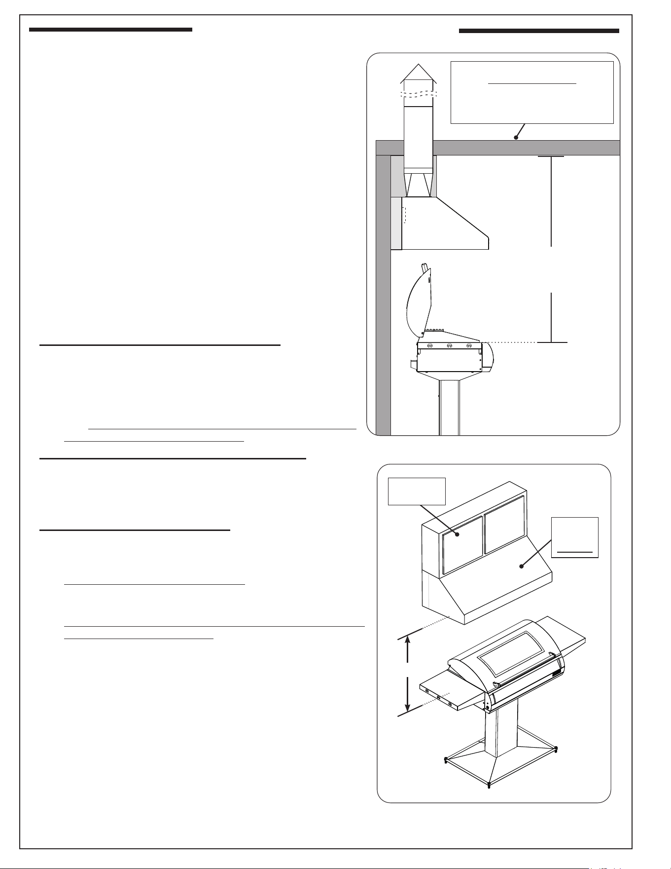
Fig. 10-2 Overhead cabinetry requirements
30" Min.
Combustible
cabinetry
Exhaust
hood
required
Fig. 10-1 Overhead (roof) requirements
EXHAUST HOOD
Combustible overhead construction:
Exhaust hood required
Non-combustible overhead
construction:
Exhaust hood highly recommended
OVERHEAD CONSTRUCTION (ROOF)
Min. 5'
from countertop to
non-combustible overhead
construction
INSTALLATION REQUIREMENTS
Installation must be performed by a qualied professional
service technician.
Any constructed outdoor area in which the appliance is
used shall comply with one of the following:
• An outdoor area with walls on three sides, and no
overhead cover
• Within a partial outdoor area that includes an overhead
cover and no more than two walls. The sidewalls may
be parallel, as in a breezeway, or at right angles to each
other
• Within a partial outdoor area that includes an overhead
cover with walls on three sides, and at least 30% or more
of the horizontal periphery of the enclosure that is open
and unrestricted
Note: All openings must be permanently open.
Note: Sliding doors, garage doors, windows, or screened
openings are not considered as permanent openings.
Refer to DIAGRAMMATICAL REPRESENTATIONS OF
OUTDOOR AREAS section.
OVERHEAD CONSTRUCTION REQUIREMENTS
Combustible overhead construction (roof):
• An exhaust hood is required. A minimum 5 foot
clearance is required between the cooking surface and
the overhead construction. (No combustible materials
are allowed within this area.) See Fig. 10-1.
• See EXHAUST HOOD section below for more details
and consult the instructions provided with the exhaust
hood for additional requirements.
Non-combustible overhead construction (roof):
• An exhaust hood is highly recommended. A minimum 5
foot clearance is required between the cooking surface
and the overhead construction. (No combustible materials
are allowed within this area.) See Fig. 10-1.
Combustible overhead cabinetry:
• An exhaust hood is required. A minimum clearance of
30" (Fig.10-2) is required between the cooking surface
and the exhaust hood. Any overhead cabinetry must be
directly above the exhaust hood. Cabinetry extending
to the left or right of the exhaust hood is not permitted.
• See EXHAUST HOOD section below for more details and
consult the instructions provided with the exhaust hood
for additional requirements.
EXHAUST HOOD
The exhaust hood helps extract smoke while cooking and
provides protection for the overhead construction.
When using an exhaust hood, the area above the cooking
surface of the grill must be covered with a hood larger than
the cooking area of the grill, and with a minimum of 1200 CFM
(cubic feet per minute) rated exhaust fan for proper outdoor
application.
Fire Magic vent hoods, spacers, and duct covers are available.
They meet all requirements. See Table 3 in the MODEL
SPECIFICATIONS section. Contact your local dealer.
For custom spacers, they must be constructed entirely of
non-combustible material only. For custom sots, they may
be constructed of wood, metal framing, etc.
11
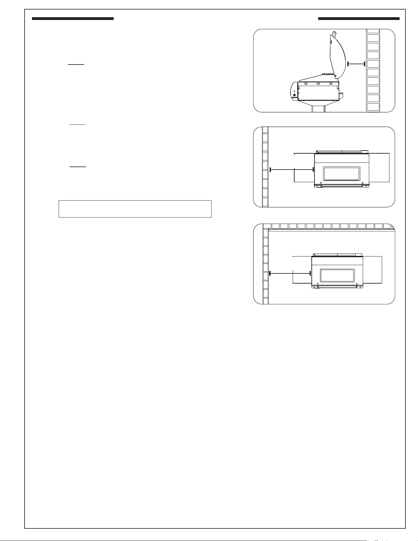
Fig. 11-1 Clearance 'A' Diagram
Min.
8"
(Clearance required
for rear wall)
Min.
24"
Min.
24"
Clearances continued on following page
CLEARANCES
Rear wall
The unit must have a minimum clearance of 8" from the rear
wall (see Fig. 11-1).
(To allow for proper ventilation and prevent dangerous
overheating.)
Side wall (if applicable)
The unit must have a minimum clearance of 24" from any
side walls (to account for variables in airow that could aect
performance). See Fig. 11-2.
Corner wall (if applicable)
The unit must have a minimum clearance of 24" from any
side walls (to account for variables in airow that could aect
performance). See Fig. 11-3.
INSTALLATION REQUIREMENTS (Cont.)
Fig. 11-3 Corner wall clearance
Fig. 11-2 Side wall clearance

12
NOTES PAGE
13
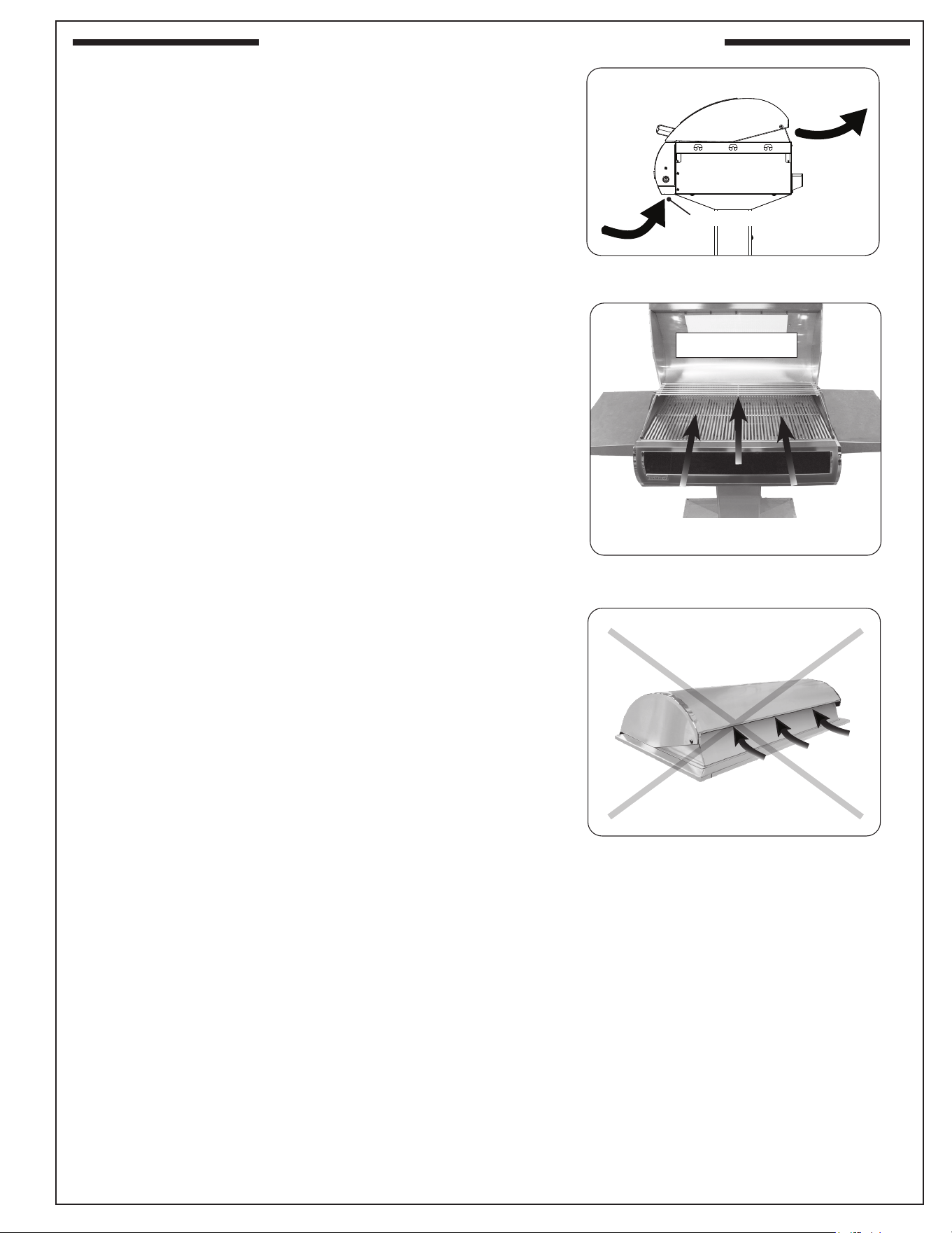
Fig. 13-2 Airow direction - CORRECT
Front air inlet (do not block)
Fig. 13-1 Airow diagram
YOU MUST PROTECT
REAR OVEN VENT FROM
PREVAILING WIND
Rear oven lid vent
INCORRECT
Fig. 13-3 Airow direction - INCORRECT
CORRECT
PLACE GRILL SO PREVAILING WIND
BLOWS TOWARD FRONT OF GRILL
COOLING AIRFLOW
Proper airow (front-to-back, Fig. 13-1) MUST be maintained
for the unit to perform as it was designed. If airow is blocked,
overheating will result. Do not block the front air inlet along the
bottom of the control panel.
CAUTION: Install the grill so that the prevailing wind blows
toward the front of the grill (Fig. 13-2). Wind
blowing into or across the rear oven lid vent
(Fig. 13-3) can cause poor performance and/
or dangerous overheating. A wind deector is
available for purchase to assist in proper airow
during windy conditions, See Table 2 for model
numbers. Follow the instructions included with
the wind deector for installation.
INSTALLATION REQUIREMENTS (Cont.)
14
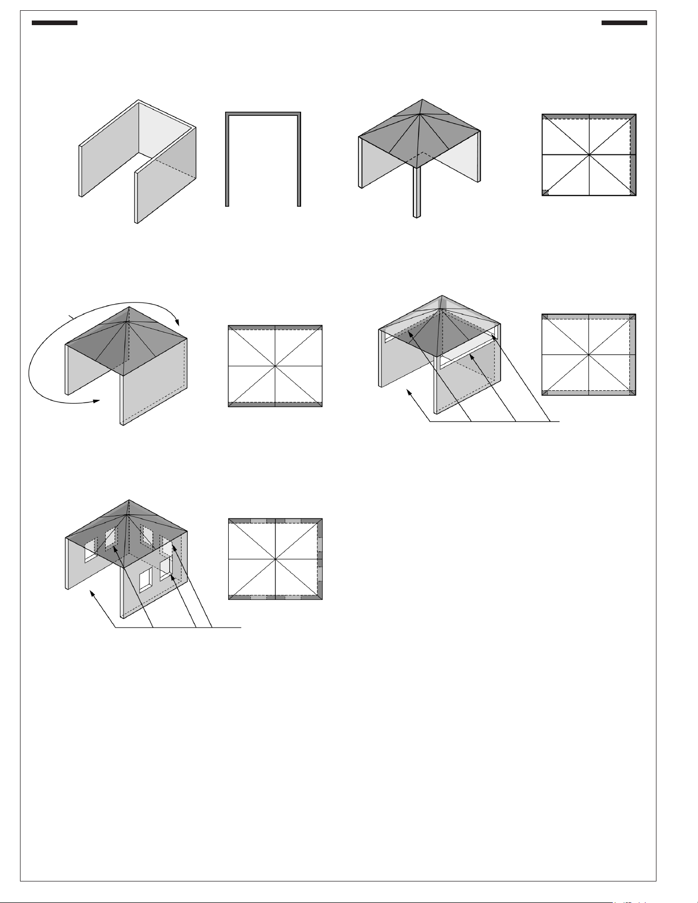
The following gures are diagrammatical representations of outdoor areas. See INSTALLATION
REQUIREMENTS section.
Fig. 14-1 Outdoor area - Example 1
Fig. 14-2 Outdoor area - Example 2
Fig. 14-3 Outdoor area - Example 3 Fig. 14-4 Outdoor area - Example 4
Fig. 14-5 Outdoor area - Example 5
Both ends open
30% or more of the horizontal
periphery of the enclosure is
open and unrestricted
30% or more of the horizontal
periphery of the enclosure is
open and unrestricted
DIAGRAMMATICAL REPRESENTATIONS OF OUTDOOR AREAS

15
• To protect against electric shock, do not immerse electrical wires, cord or plugs (as applicable) in water or
other liquid.
• Allow the unit to cool before fully shutting o the main power source for cleaning, servicing, taking o parts
or when unit will not be in use.
• Do not operate any outdoor cooking appliance with damaged wiring, or after the appliance malfunctions or
has been damaged in any manner. Contact the manufacturer for repair.
• Do not use an outdoor cooking appliance for purposes other than intended.
• Use only a properly wired and inspected 240VAC (30 AMP minimum, single-phase) GROUNDED
three-wire dedicated Ground Fault Circuit Interrupter (GFCI) circuit breaker with the addition of an
in-line electrical disconnect OR removable plug with outlet with this outdoor cooking appliance. The
electrical disconnect, and plug with receptacle MUST be outdoor-rated WEATHER-PROOF and IN-
USE COVERED.
• Use only a GFCI circuit breaker rated for 30 AMPS with this outdoor cooking appliance.
• Use only 10AWG (or larger) wires suitable for at least 221° F (105° C).
• The provisions of the National Electric Code as well as any local codes must be observed when
installing the product.
ELECTRICAL SAFETY
16
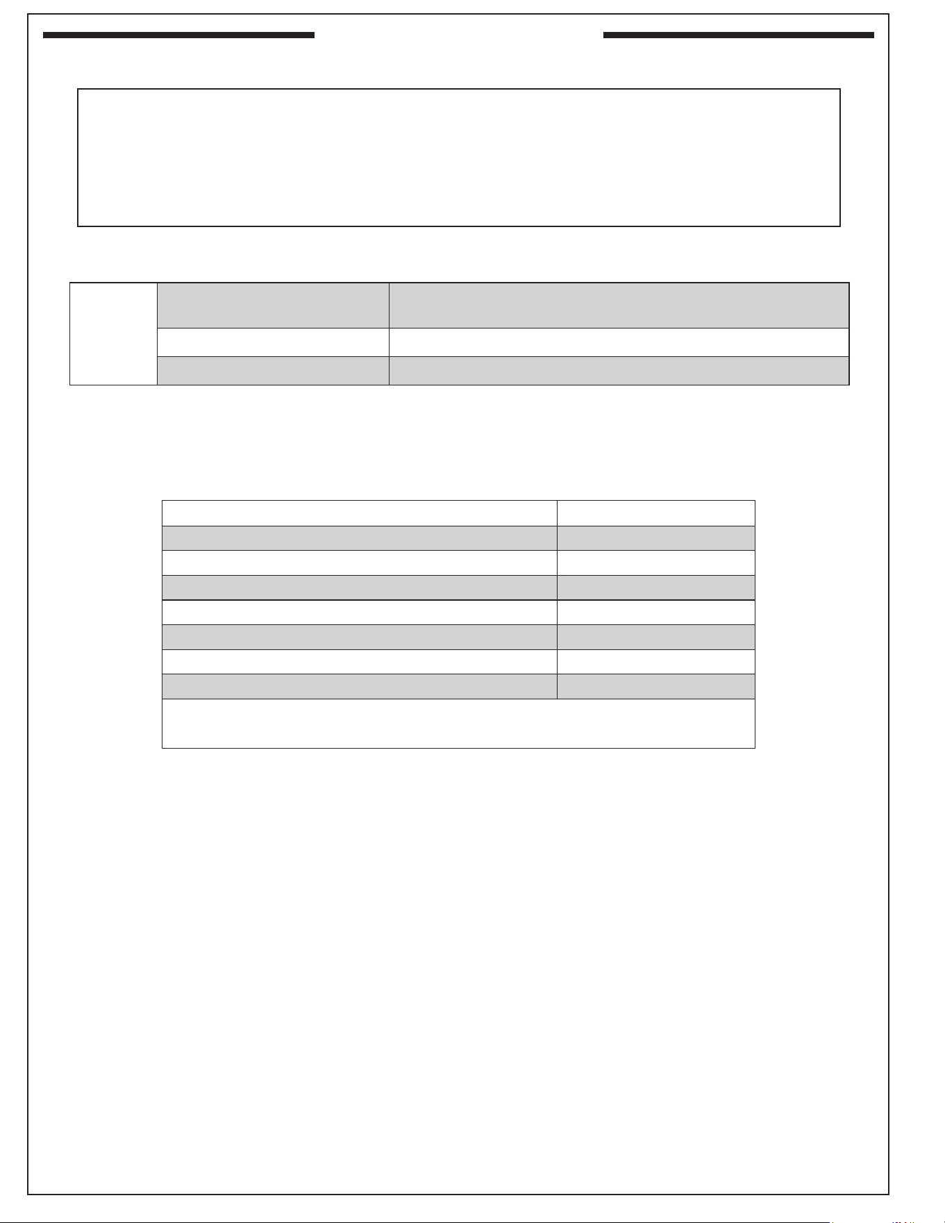
MODEL SPECIFICATIONS
EL500s
Input electrical requirements
230/240VAC / 30 AMP minimum / single-phase / 50/60 Hz
/ GFCI circuit breaker
Appliance rating 230/240VAC / 6,000 watts / 25 AMP / 50/60 Hz
Ingress protection IPX4
Table 1 - Product Specications
The unit rating label is located behind the unit. The unit serial number is located:
• on the underside of the drip tray handle (on a thermal label). It is recommended that the drip tray
rst be removed and cleaned / emptied of its contents, then turned over to view.
• axed to the grill body behind the control panel (on an aluminum tag)
• on the unit rating label located behind the unit
EL500s
Wind deector model # * 23116-19
Protective cover 3665F
Cooking grid scraper 3502-E
Griddle accessory 3522
Fire Magic vent hood model # * 36-VH-7
ŧ
Fire Magic vent hood spacer model # * 36-VH-7-02
ŧ
Fire Magic vent hood duct cover model # * 36-VH-7-DC
ŧ
*
If applicable, not included
ŧ This model meets the minimum size requirements; larger models are also acceptable.
Table 2 - Grill Supporting Products
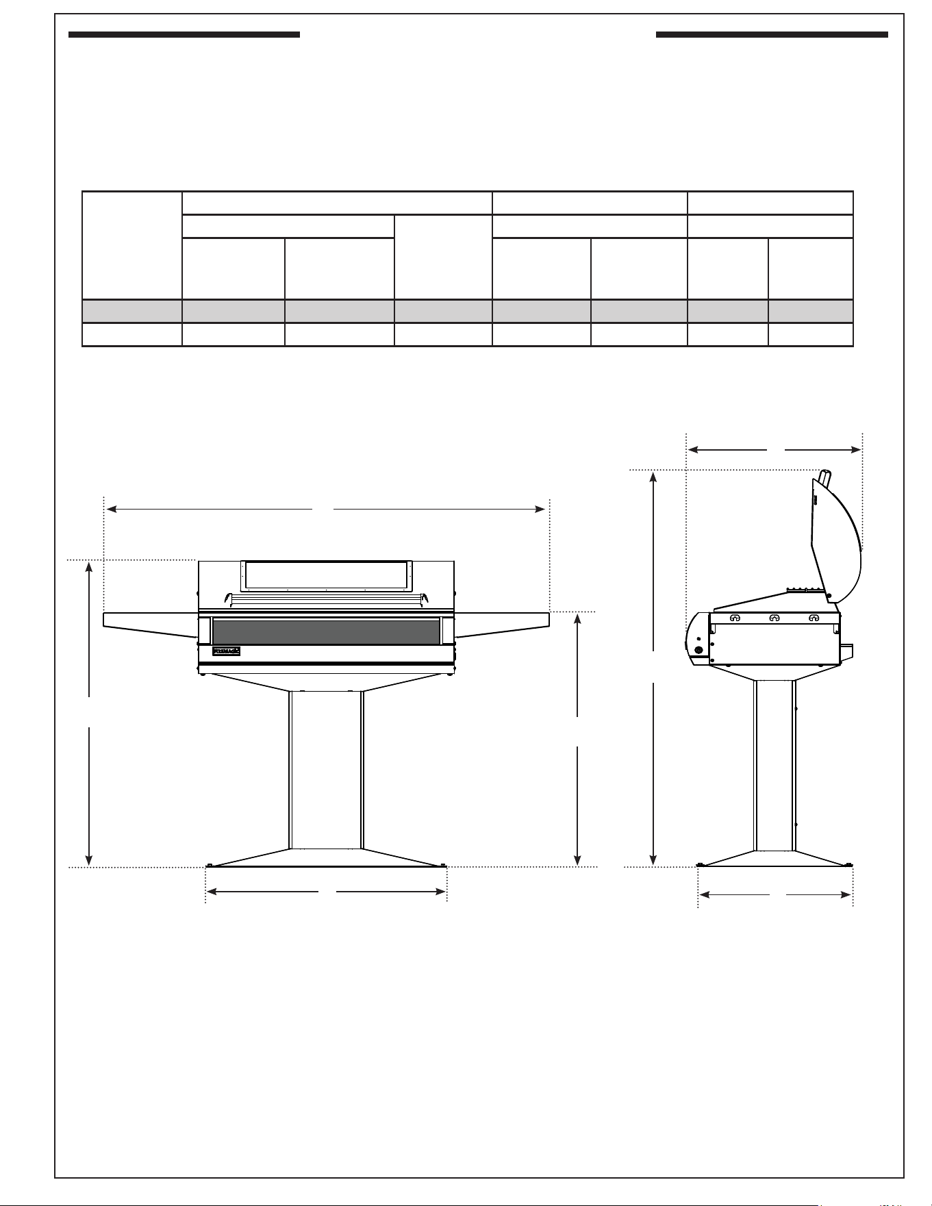
17
MODEL SPECIFICATIONS (CONT.)
Height Width Depth
Floor to top
Floor to top
of shelf (C)
(Left to right) (Front to back)
With oven lid
OPEN
(A)
With oven lid
CLOSED
(B)
Post base
(D)
Shelves
(E)
Post base
(F)
Maximum
outer
(G)
P6 Series 57
4
/
5
" 43
1
/
2
" 37" 30
1
/
4
" 56
1
/
8
" 20
1
/
4
" 23
3
/
4
"
AP Series 52
4
/
5
" 38
1
/
2
" 32" 30
1
/
4
" 56
1
/
8
" 20
1
/
4
" 23
3
/
4
"
Table 3 - Stand Alone Post Dimensions
Fig. 17-1
G
F
A
D
B
C
E
18
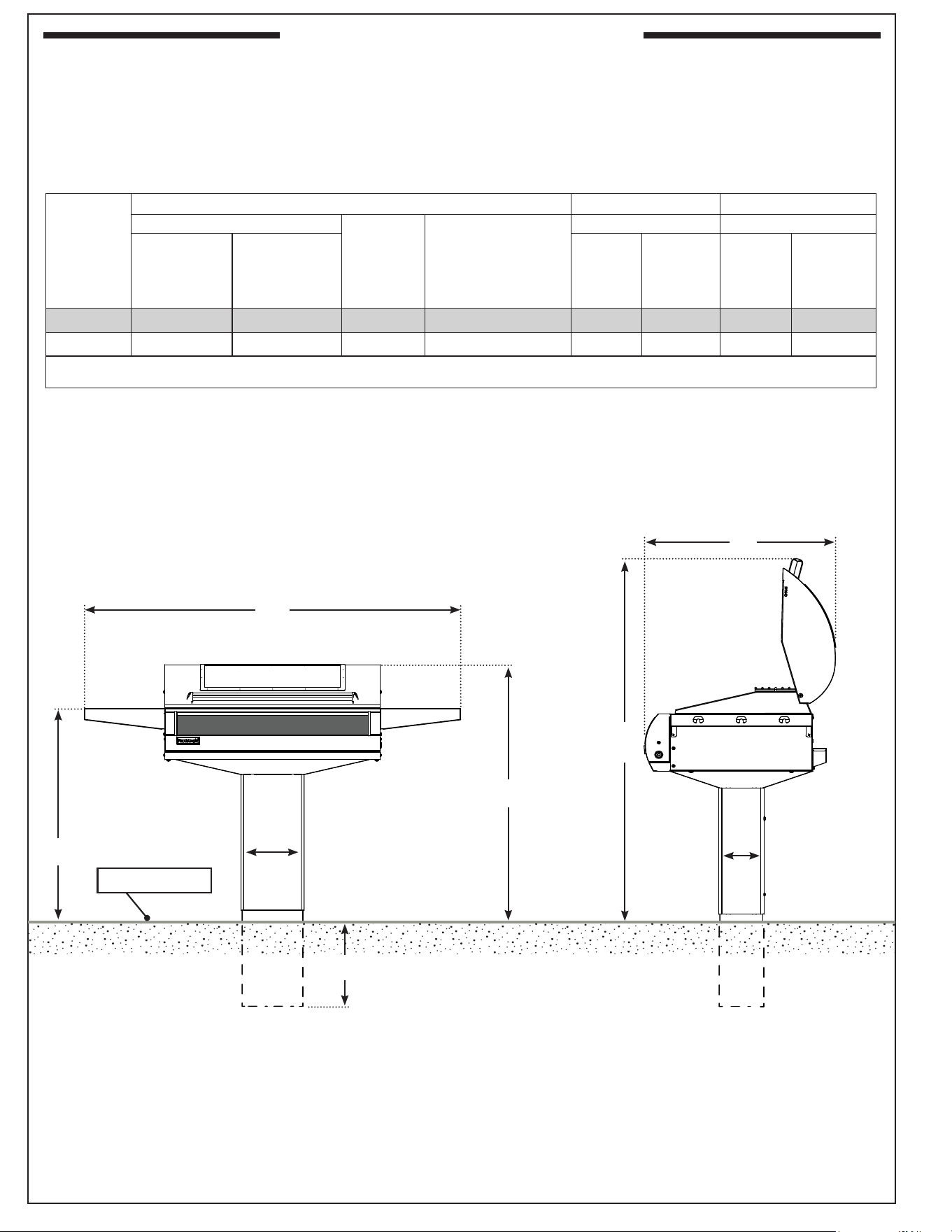
MODEL SPECIFICATIONS (CONT.)
Ground level
E
D
G
H
C
F
B
A
Model
Height* Width Depth
Floor to top
Floor to top
of shelf
(C)
Floor to bottom of
extension below
ground
(D)
Left to right Front to back
With oven lid
OPEN
(A)
With oven lid
CLOSED
(B)
Post
(E)
Shelves
(F)
Post
(G)
Maximum
outer
(H)
G6 Series 57
4
/5" 43
1
/2" 37” 18” 9
3
/8" 56
1
/8" 5
1
/2" 23
3
/4"
AG Series 52
4
/5" 38
1
/2" 32” 18” 9
3
/8" 56
1
/8" 5
1
/2" 23
3
/4"
*Note: Height dimensions are approximate from ground level once installed.
Table 4 - In-Ground Post Grill Dimensions
(AG Series shown)
19
MODEL SPECIFICATIONS (CONT.)
Note: In addition, a wire diagram can be found axed to
the rear of the unit.
Digital thermometer /
thermostat
Fig. 19-1
Ceramic
terminal block
harness
Thermostat
manual reset
switch
Power
supply
Ceramic
terminal
block
Power input
block
Thermal
switch
Heating
element
Panel mount
relay
DC brushless fan
Thermostat wire
harness
Main wire
harness
Thermocouple
Relay
wire
Wire harness
extension
Meat probe
jack
Thermometer
power switch
Input wire
harness
GND
EL500s (single digital control models)
WIRING DIAGRAM
L1
L2
~ 230/240
20
~ 230/240
Note: In addition, a wire diagram can be found axed to
the rear of the unit.
Digital thermometer /
thermostat
EL500s (dual digital control models)
WIRING DIAGRAM
Fig. 20-1
Ceramic terminal
block harness
Thermal switch
Power
supply
Ceramic
terminal
block
Power input
block
Thermostat manual
reset switch
Thermal
switch
Heating
element
Panel mount
relay
DC brushless fan
Thermostat wire
harness
Main wire
harness
Thermocouple
Relay
wire
Wire harness
extension
Meat probe
jack
Thermometer
power switch
Input wire
harness
GND
L1
L2
MODEL SPECIFICATIONS (CONT.)
21
1
20
2
19
28
9
26
27
32
21
IMPORTANT
Remove all packing
material (including any
protective coatings) and
discard prior to use.
10
10
Replacement parts can
be ordered from your
local Fire Magic dealer.
18
31
ELECTRIC GRILL REPLACEMENT PARTS LIST
6
8
7
4
3
30
(Dual digital control
model shown)
Your unit is packaged in (2) boxes.
13
29
29
5
11
12
22
22
EL500s
Item Description Part No. Qty.
1. Stainless cooking grid (set of 2) 3555-DS-2 2
2. Heating element 23116-16 2
3. Heating element rear support bracket 23115-52 2
4. Zone divider * 23116-02 1
5. Vaporizer panel (set of 4) 3066-S-4 1
6. Handle assy. 23116-03 1
7. Oven lid w/ window (only available on dual control models) 23116-04 1
or Oven lid w/o window
t
23116-12 1
8. Magic view window glass w/ kit * 23116-10 1
9. Warming rack 3681 1
10. Rigid shelves 25116-02 2
11. Patio post mount base w/ hardware (P6 models) 25116-01 1
or Patio post mount base w/ hardware (AP models)
t
25116-03 1
or In-ground post mount base w/ hardware (G6 models) 25116-04 1
or In-ground post mount base w/ hardware (AG models)
t
25116-05 1
12. Patio mount hardware kit w/ lag shields and lag screws 24330-25 1
13. Digital thermometer / thermostat 23115-55 1 or 2
▲
14. Wire harness adapter for digital thermometer / thermostat
t
24187-47 1 or 2
▲
15. Complete raceway w/ electronics (single control model)
t
23116-13 1
or Complete raceway w/ electronics (dual control model)
t
23116-05 1
16. Main harness
t
23116-06 1
17. Harness extension
t
23116-07 1
18. Control panel w/ raceway & electronics (single control model) 23116-14 1
or Control panel w/ raceway & electronics (dual control model) 23116-08 1
or Control panel w/ glass & no electronics (single control model) 23116-21 1
or Control panel w/ glass & no electronics (dual control model) 23116-22 1
19. Meat probe 24187-21 1
20. Drip tray 3097 1
21. Drip tray liners (set of 4) 3558 1
22. Thermometer power switch 24195-16 1
23.
Fan
t
23115-15 1 or 2
▲
24.
Relay
t
23115-16 2
25.
Power supply
t
24187-66 1
26.
Ceramic terminal block
24187-71 4
27.
Junction box
24187-70 1
28. Grid lifter 3519H 1
29. Thermal switch 23116-11 1 or 2
▲
30. Thermostat manual reset switch 23116-20 1
31. Meat probe bamboo storage box 24187-21-SB 1
32. Oven lid side handle kit (included w/ AP Series only) 3600-51 1
*
If equipped
t Not shown
▲
Single control model: qty 1, dual control model: qty 2
ELECTRIC GRILL REPLACEMENT PARTS LIST (CONT.)
23
IMPORTANT SAFETY INFORMATION
INSTALLATION PREPARATION
INSTALLATION
BE CAREFUL
If not installed and used correctly per these instructions,
this product can cause serious injury.
ASSEMBLY REQUIRES TWO OR MORE PEOPLE.
EXERCISE EXTREME CARE DURING ASSEMBLY AND INSTALLATION.
CAUTION: Installation and maintenance must be done by a qualied professional service technician. Read
these instructions before installing this unit. Be sure you understand all safety precautions and
warnings contained in this manual.
A. FOR OUTDOOR USE ONLY.
B. When shutting the unit down—be sure to allow time for the unit to cool down completely (via the fans)
before TURNING OFF THE MAIN ELECTRICAL SUPPLY.
C. WARNING: DO NOT MODIFY THIS UNIT OR ITS CONTROLS. Any changes will be dangerous. Improper
installation or use of the unit can cause serious injury or death.
D. Check state and local codes to determine if the unit is permitted in your locality before installation.
BEFORE YOU BEGIN
Important: Prior to installation ensure that all specications, dimensions, electrical requirements, and
minimum clearances stated in this manual are observed. You must read all warnings and
safety information, and understand all of the information in this manual. All installation
requirements must be observed and met.
• Conrm the installation site accommodates the unit installation method per the requirements in this manual.
• Be sure the power supply (circuit breaker) is turned o at its source.
• Wear gloves and use extreme caution whenever installing and handling this product and its
accessories as certain components have sharp edges that can cause personal injury.
• Remove all packing material (including any protective coatings) and discard prior to installation.
LOCATION
While following all requirements and safety information in this manual; determine and prepare the location of
the unit:
• Patio mount: a hard and level surface
• In-ground: a hole in the ground (18" left to right by 12" front to back, 18
1
/2" deep)
Important: The electrical setup must be considered when determining the location of the unit. See
ELECTRICAL SETUP section for details.
24
INSTALLATION PREPARATION (CONT.)
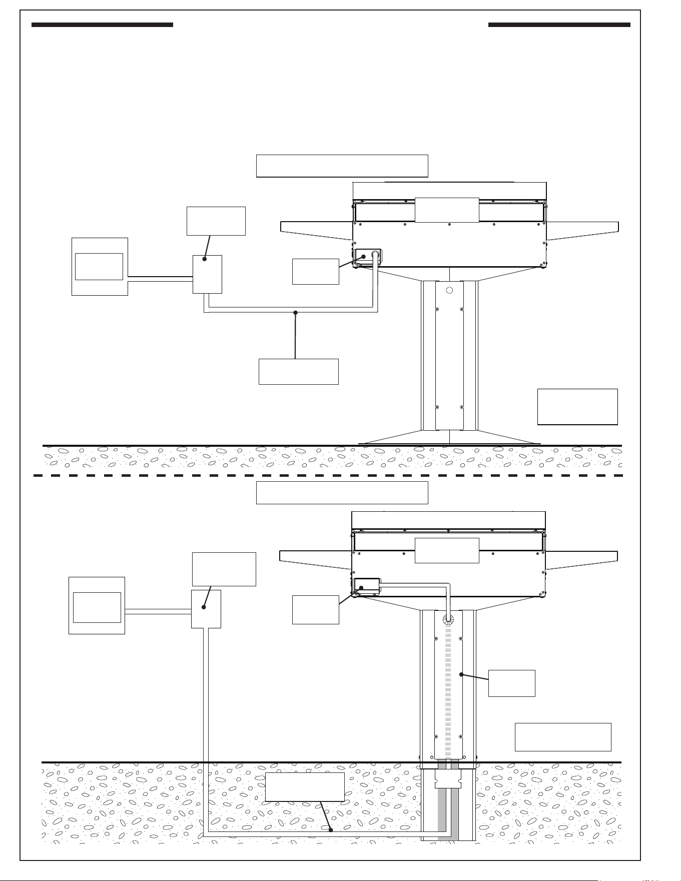
INSTALLATION OVERVIEW
Electrical wiring can be routed either underground, up the post base, and into the junction box,
or above ground, routed directly to the junction box. Refer to the methods outlined below for
proper electrical setup.
Important: Ensure your installation method complies with local codes. Review the ELECTRICAL
SETUP section on the following page for additional details.
ABOVE-GROUND METHOD
UNDERGROUND METHOD
Electrical
panel
Electrical
disconnect
Junction
box
Electrical run:
above-ground
Patio mount
shown
In-ground post
shown
Electrical run:
underground
Access
plate
Electric grill
rear view
Electric grill
rear view
Junction
box
Electrical
panel
Electrical
disconnect
Fig. 24-1
Fig. 24-2
25
ELECTRICAL SETUP
All electrical setup of this unit MUST be performed by a licensed electrician.
THIS UNIT IS DESIGNED FOR DIRECT HARD WIRING AND MUST BE POWERED BY A DEDICATED
GFCI CIRCUIT BREAKER. THE CIRCUIT BREAKER MUST BE RATED FOR 230/240VAC / 30 AMP
MINIMUM / 50/60HZ.
• The external wiring source can be routed up the post base from underground, or externally straight
into the junction box.
• The external wiring source should be a exible conduit or an approved exible cable (follow
local codes) suitable for this installation, and is of proper size to carry the load (10AWG or larger,
suitable for 221° F [105° C]).
• The appliance must be installed with the addition of an independent electrical disconnect OR
removable plug with outlet that is easily accessible. The electrical disconnect or plug conguration
must be installed in-line between the unit and circuit breaker. The disconnect or plug conguration
must be rated to properly carry the load. See Table 1 in the MODEL SPECIFICATIONS section,
IMPORTANT SAFEGUARDS section and the ELECTRICAL SAFETY section for all requirements.
• The unit must be easily disconnected from power for future maintenance and servicing.
CAUTION: Installation MUST be performed by a qualied professional service technician. OBSERVE THE
NATIONAL ELECTRIC CODE AND ALL LOCAL CODES.
• To gain access to the inside of the post, unscrew and carefully open the access plate on the rear
of the post using a medium Phillips-head screwdriver. Retain the screws.
INSTALLATION PREPARATION (CONT.)
REFER TO THE FOLLOWING PAGES TO LOCATE THE APPROPRIATE
SECTION FOR YOUR INSTALLATION METHOD:
PATIO MOUNT INSTALLATION
• Above-Ground Electrical Install Method
• Underground Electrical Install Method
OR
IN-GROUND POST INSTALLATION
• Above-Ground Electrical Install Method
• Underground Electrical Install Method
26
CAUTION: THE GRILL AND POST BASE ARE HEAVY AND
REQUIRES TWO OR MORE PEOPLE FOR
SAFE HANDLING.
INSTALLATION (ABOVE-GROUND METHOD)
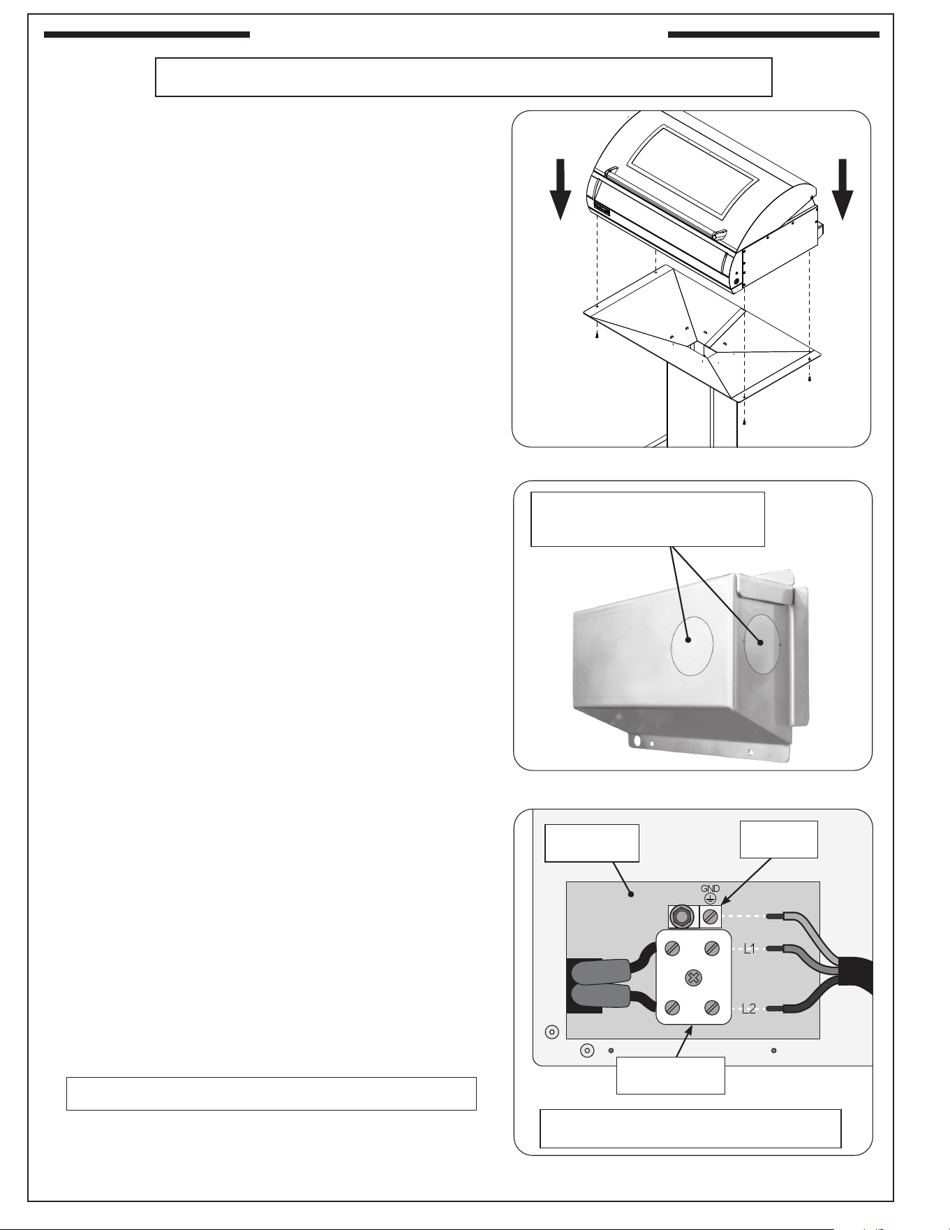
Mount Electric Grill To Post Base Assembly
It is not required to remove the control panel to install
this unit.
DO NOT lift the unit from the control panel when installing.
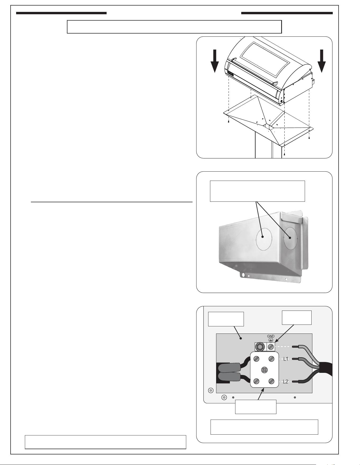
1. Carefully position the post base assembly at its designated
location.
2. Carefully place and align the electric grill onto the top of
the post assembly. Fasten the electric grill to the post base
assembly using the 4 included Phillips-head screws. See
Fig. 26-1.
Route Electrical To Rear Of Electric Grill
Refer to the INSTALLATION OVERVIEW section for an example
of the above-ground electrical installation method.
1. Route your electrical supply to the rear vicinity of the unit.
Observe the National Electric Code and all local codes.
2. Remove the junction box located on the rear of the unit.
Select and remove a knockout from the junction box that
will best suit your electrical setup. Route the wiring through
the selected knockout opening. See Fig. 26-2.
Note: Adding a strain relief bushing to the opening is
recommended (not included).
3. Connect the wires to the ceramic terminal block. Reference
the wiring information below and Fig. 26-3.
Line 1: Connect to L1 - top portion of ceramic terminal
block
Line 2: Connect to L2 - bottom portion of ceramic terminal
block
Ground: Connect to GND (ground) - aluminum grounding
lug
4. Ensure all wire connections are fully secure, switch ON the
electrical system and test the power to the unit.
5. Secure the junction box back onto the grill.
Secure Post Base Plate
Important: The patio mount base must be securely fastened
to a stable, level surface to ensure the grill remains
xed and upright at all times.
Ensure proper placement of the planned grill location and mark
the 4 holes. Drill the marked holes to a
1
/2" diameter x 1
1
/2"
depth. Insert the lag shields (see PARTS LIST) into the holes,
being sure that they are ush with the ground.
Align the holes on the post base over the lag shields in the
ground. Secure the base with the lag screws (see PARTS LIST)
using a
7
/16" nut driver.
~ 230-240
Fig. 26-3 Wire connection diagram
Connections / Circuit breaker rating:
230/240VAC / 30 AMP minimum / 50/60 Hz
Junction box
opening
Grounding
lug
Fig. 26-2 Junction box knockouts
1. Select and remove a knockout
2. Feed electrical through opening
3. Make connections to unit
Ceramic
terminal block
Fig. 26-1 Fasten grill to post base assembly
PATIO MOUNT INSTALLATION
Proceed to the COMMON INSTALLATION section
ABOVE-GROUND ELECTRICAL INSTALL METHOD

27
PATIO MOUNT INSTALLATION (CONT.)
CAUTION: THE GRILL AND POST BASE ARE HEAVY AND
REQUIRES TWO OR MORE PEOPLE FOR
SAFE HANDLING.
INSTALLATION (UNDERGROUND METHOD)
Refer to the INSTALLATION OVERVIEW section for an
example of the underground electrical installation method.
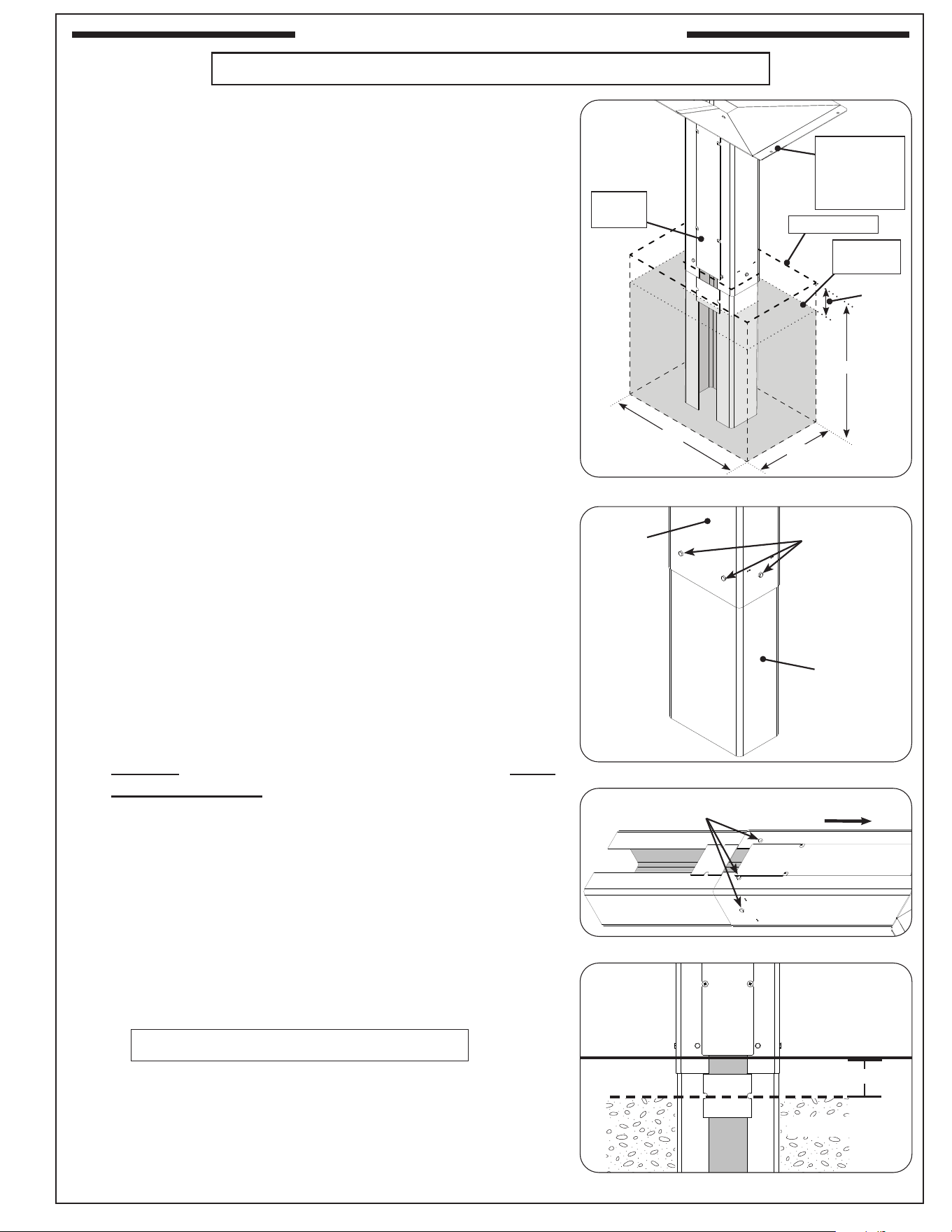
Route Electrical Through Post Base Assembly
1. Route the electrical wiring up from underground to the
planned grill location. Observe the National Electric Code
and all local codes.
Note: Ensure that the electrical wiring is of sucient length
to accommodate the length of the post, exit through
the top portion of the access plate and connect to the
junction box. An alternative option is to provide only
enough wiring to install a junction box (not included)
inside the post and extend the wiring from that point
once the post is secured.
2. Locate the rear access plate on the post base assembly
and remove it by unscrewing the four Phillips-head screws.
See Fig. 27-1, A.
3. Remove the knockout from the upper portion of the access
plate. See Fig. 27-1, B.
Note: Use one of the two knockouts as applicable for
your installation. The plastic grommet provided
is intended to be used with the inner knockout.
4. While placing the post base assembly in position:
• Tilt the post base slightly and carefully feed the electrical
wires (coming from underground) up from under the
post base (See Fig. 27-2, A)
• Guide wiring up the post assembly (See Fig. 27-2, B)
• Carefully rest the post base at its designated location
(See Fig. 27-2, C)
• Feed the electrical through the knockout hole of the
access plate and re-fasten the access plate (See Fig.
27-2, D)
• Install the grommet (included) onto the electrical and
slide the grommet up against the knockout hole and
snap into place (See Fig. 27-2, E)
Fig. 27-1 Remove access plate and knock-out
Procedure continued on following page
Fig. 27-2 Remove access plate and knock-out
A
Remove
access plate
B
Remove
knockout
A
B
D
C
Route
electrical up
through post
Guide wiring
Position
post base
Guide through
knockout opening
& re-fasten plate
Install
grommet
(included)
E
UNDERGROUND ELECTRICAL INSTALL METHOD
28
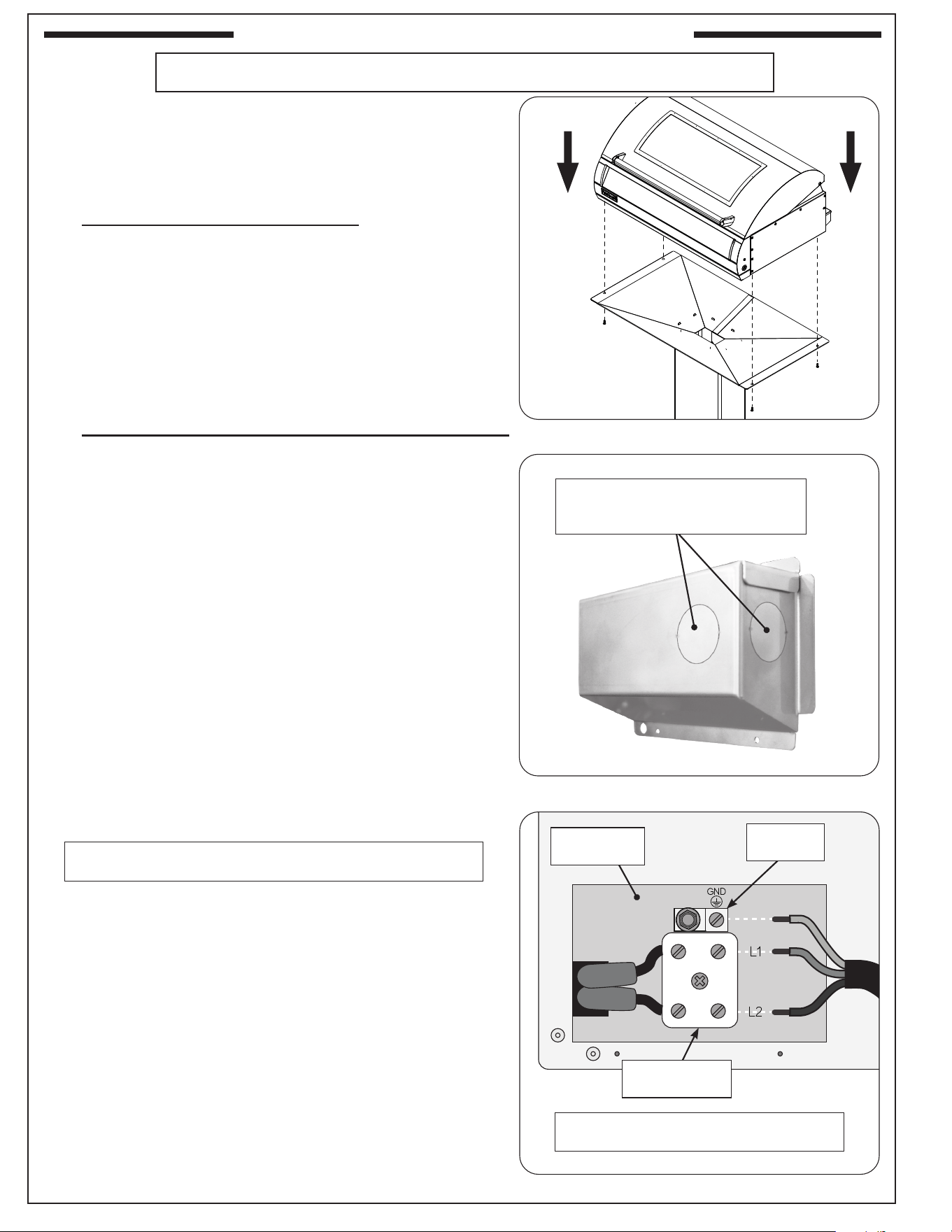
Mount Electric Grill To Post Base Assembly
It is not required to remove the control panel to install
this unit.
DO NOT lift the unit from the control panel when
installing.
Carefully place and align the electric grill onto the top of
the post assembly. Fasten the electric grill to the post base
assembly using the 4 included Phillips-head screws. See
Fig. 28-1.
Connect Electrical To Rear Of Electric Grill
1. Remove the junction box located on the rear of the unit.
Select and remove a knockout from the junction box
that will best suit your electrical setup. See Fig. 28-2.
2. Take the wiring that is exiting the top portion of the
post access plate and route it through the selected
knockout opening on the junction box. Reference the
INSTALLATION OVERVIEW section for a summarized
view of this installation.
Note: Adding a non-metallic strain relief bushing to the
opening is recommended (not included).
3. Connect the wires to the ceramic terminal block.
Reference the wiring information below and Fig. 28-3.
Line 1: Connect to L1 - top portion of ceramic terminal
block
Line 2: Connect to L2 - bottom portion of ceramic
terminal block
Ground: Connect to GND (ground) - aluminum
grounding lug
4. Ensure all wire connections are fully secure, switch
ON the electrical system and test the power to the unit.
5. Secure the junction box back onto the grill.
Secure Post Base Plate
Important: The patio mount base must be securely
fastened to a stable, level surface to ensure
the grill remains xed and upright at all times.
Ensure proper placement of the planned grill location and
mark the 4 holes. Drill the marked holes to a
1
/2" diameter
x 1
1
/2" depth. Insert the lag shields (see PARTS LIST) into
the holes, being sure that they are ush with the ground.
Align the holes on the post base over the lag shields in the
ground. Secure the base with the lag screws (see PARTS
LIST) using a
7
/16" nut driver.
Fig. 28-3 Wire connection diagram
Fig. 28-2 Junction box knockouts
1. Select and remove a knockout
2. Feed wires through opening
3. Make connections to unit
PATIO MOUNT INSTALLATION (CONT.)
Proceed to the COMMON INSTALLATION section
Fig. 28-1 Fasten grill to post base assembly
UNDERGROUND ELECTRICAL INSTALL METHOD (CONT.)
~ 230-240
Connections / Circuit breaker rating:
230/240VAC / 30 AMP minimum / 50/60 Hz
Junction box
opening
Grounding
lug
Ceramic
terminal block
29
IN-GROUND POST INSTALLATION
ABOVE GROUND ELECTRICAL INSTALL METHOD
DO NOT MOUNT THE ELECTRIC GRILL TO THE POST
ASSEMBLY AT THIS POINT.
PREPARE FOR INSTALLATION
Consult a qualied professional installer / licensed contractor.
The method of electrical installation in this section is for routing
the electrical supply directly to the junction box. Refer to the
INSTALLATION OVERVIEW section for an example of the above-
ground electrical installation method.
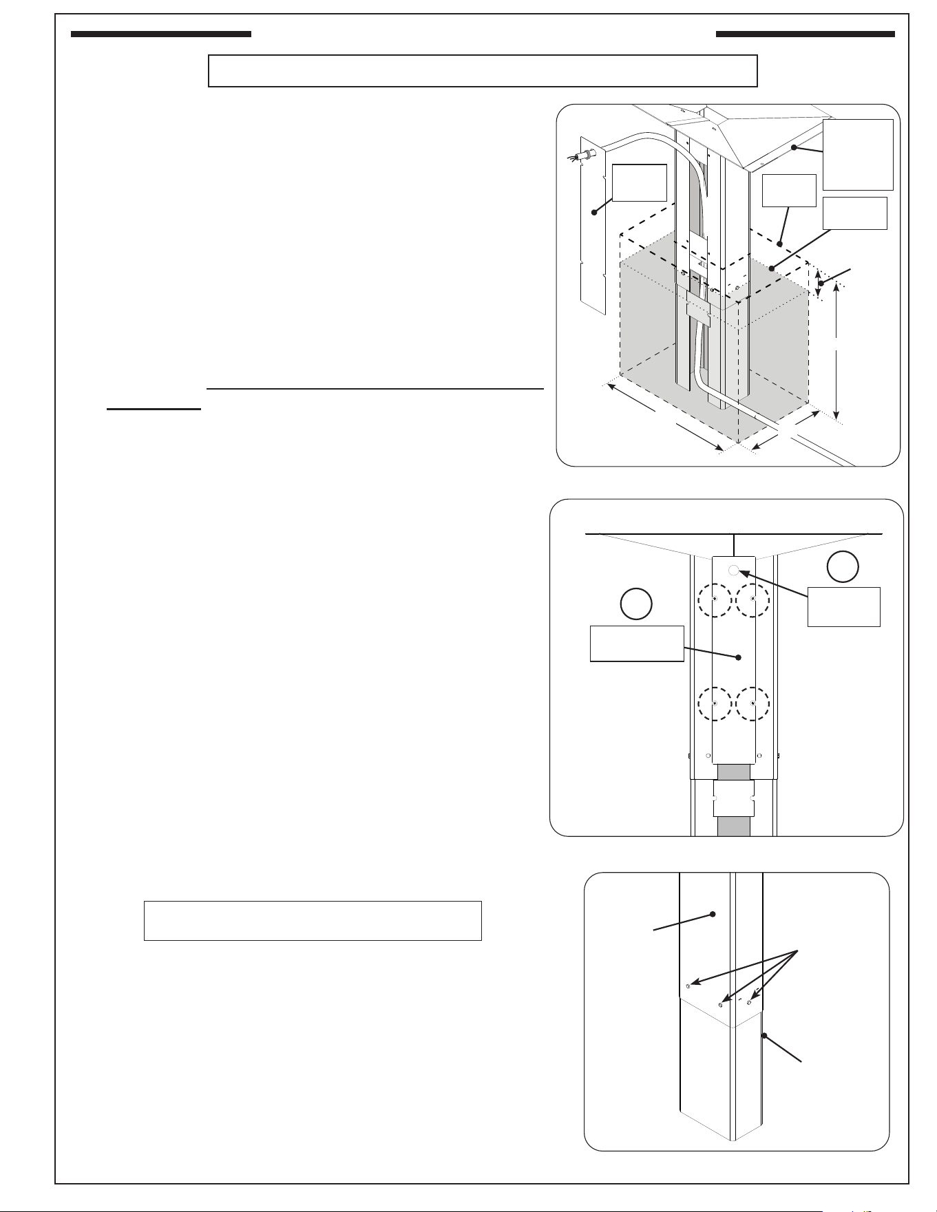
ATTACH POST EXTENSION
1. Attach the extension to the bottom of the grill post so that
the open portion is facing the same direction as the access
plate and the six holes in the extension line up with the six
(6) weld-nuts in the post (see Fig. 29-1 and Fig. 29-2).
2. From outside the joined post and extension, insert one of
the
1
/
4
" - 20 X
1
/
2"
bolts (supplied) into each of the six (6)
bolt holes and tighten each bolt using a
7
/
16
" socket driver
or wrench (see Fig. 29-2 and Fig. 29-3).
Note: There is one hole on the left and right sides of the
post, and two holes on the front and back.
POUR CONCRETE & PLACE POST IN GROUND
1. Dig a hole for the post and extension approximately 18" wide,
12" front-to-back, and 18
1
/2" deep. See Fig. 29-1.
Note: The actual depth of the hole should be such that the top
of the post mount assembly is approximately 29
1
/2" (G6
models) and 24
1
/2" (AG models) above ground level.
2. Prepare the concrete to be used for the install.
3. Carefully orient the post into the installation hole and verify
proper positioning. See Fig. 29-1.
4. Remove the post.
5. Pour the concrete mixture into the hole to approximately 3-5"
below the ground level. See Fig. 29-4.
6. While the concrete is still wet, carefully lower the extended
grill post.
7. Orient the post assembly per plan, and support it so that it
remains in an up right, level and aligned position while the
concrete drys.
Post
Extension
(position
access plate
side toward
back)
Install
provided bolts
into 6 holes
around post
Fig. 29-2 Install extension to post
Bolts
To grill
Fig. 29-3 Fasten extension to post
Ground level
Concrete level
Fig. 29-4 In-ground post orientation
3-5"
Procedure continued on following page
Fig. 29-1 Installation overview
Provide
support to
ensure level
and aligned
Access
plate
12"
18
1
/2"
18"
Concrete
level
Ground level
3-5"
30
IN-GROUND POST INSTALLATION (CONT.)
ABOVE GROUND ELECTRICAL INSTALL METHOD (CONT.)
Mount Electric Grill To Post Base Assembly
It is not required to remove the control panel to mount the
electric grill.
DO NOT lift the unit from the control panel when installing.
1. Verify the concrete is completely dry.
2. Carefully place and align the electric grill onto the top of
the post assembly. Fasten the electric grill to the post base
assembly using the 4 included Phillips-head screws. See
Fig. 30-1.
Route Electrical To Rear Of Electric Grill
Refer to the INSTALLATION OVERVIEW section for an
example of the above-ground electrical installation method.
1. Route your electrical supply to the rear vicinity of the unit.
Observe the National Electric Code and all local codes.
2. Remove the junction box located on the rear of the unit.
Select and remove a knockout from the junction box that
will best suit your electrical setup. Route the wiring through
the selected knockout opening. See Fig. 30-2.
Note: Adding a strain relief bushing to the opening is
recommended (not included).
3. Connect the wires to the ceramic terminal block. Reference
the wiring information below and Fig. 30-3.
Line 1: Connect to L1 - top portion of ceramic terminal
block
Line 2: Connect to L2 - bottom portion of ceramic terminal
block
Ground: Connect to GND (ground) - aluminum grounding
lug
4. Ensure all wire connections are fully secure, switch ON the
electrical system and test the power to the unit.
5. Secure the junction box back onto the grill.
Fig. 30-3 Wire connection diagram
Fig. 30-2 Junction box knockouts
1. Select and remove a knockout
2. Feed electrical through opening
3. Make connections to unit
Fig. 30-1 Fasten grill to post base assembly
Proceed to the COMMON INSTALLATION section
~ 230-240
Connections / Circuit breaker rating:
230/240VAC / 30 AMP minimum / 50/60 Hz
Junction box
opening
Grounding
lug
Ceramic
terminal block
31
IN-GROUND POST INSTALLATION (CONT.)
UNDERGROUND ELECTRICAL INSTALL METHOD
DO NOT MOUNT THE ELECTRIC GRILL TO THE POST
ASSEMBLY AT THIS POINT.
PREPARE FOR INSTALLATION
Consult a qualied professional installer / licensed contractor.
The method of electrical installation in this section is for routing
the electrical supply underground, up the post assembly, and
out to the junction box. Refer to the INSTALLATION OVERVIEW
section and Fig. 31-1 for an example of the underground electrical
installation method.
ROUTE ELECTRICAL WIRING TO INSTALLATION SITE
1. Route the electrical wiring up from underground to the planned
grill location. Observe the National Electric Code and all
local codes.
Note: Ensure that the electrical wiring is of sucient length to
accommodate the length of the post, exit through the top
portion of the access plate and connect to the electric
grill's junction box. An alternative option is to provide only
enough wiring to install an additional junction box (not
included) inside the post and extend the wiring from that
point once the post is secured.
2. Locate the rear access plate on the post base assembly
and remove it by unscrewing the four Phillips-head screws.
See Fig. 31-2, A.
3. Remove the knockout from the upper portion of the access
plate. See Fig. 31-2, B.
Note: Use one of the two knockouts as applicable for
your installation. The plastic grommet provided is
intended to be used with the inner knockout.
ATTACH POST EXTENSION
1. Attach the extension to the bottom of the grill post so that
the open portion is facing the same direction as the access
plate and the ve holes in the extension line up with the six
(6) weld-nuts in the post (see Fig. 31-3).
Fig. 31-1 Installation overview
Fig. 31-2 Remove access plate and knock-out
A
Remove
access plate
B
Remove
knockout
Provide
support
to ensure
level
Access
plate
Post
Extension
(position
access plate
side toward
back)
Install
provided bolts
into 6 holes
around post
Fig. 31-3 Install extension to post
12"
18
1
/2"
18"
Concrete
level
Ground
level
3-5"
Procedure continued on following page
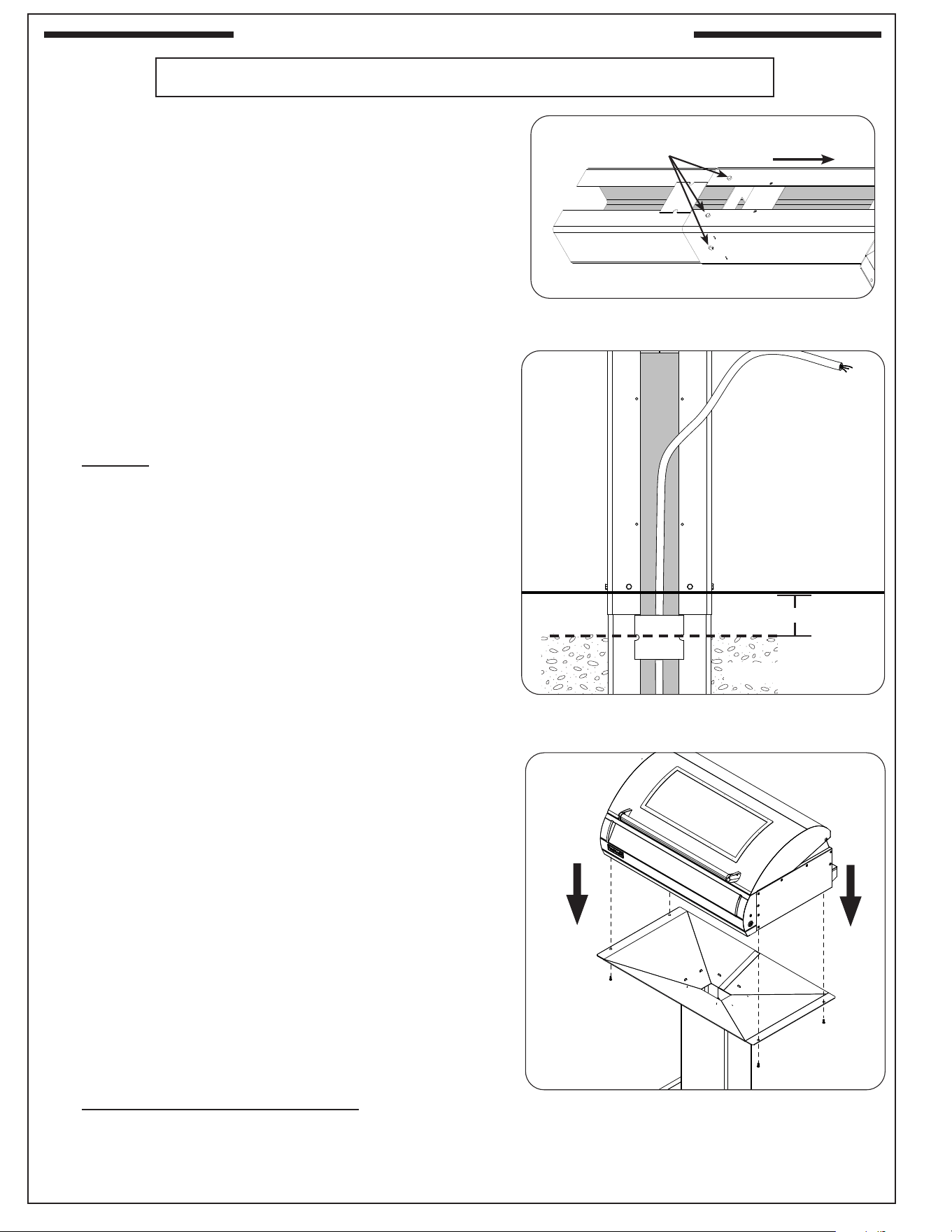
32
IN-GROUND POST INSTALLATION (CONT.)
UNDERGROUND ELECTRICAL INSTALL METHOD (CONT.)
2. From outside the joined post and extension, insert one of
the
1
/
4
" - 20 X
1
/
2"
bolts (supplied) into each of the six (6)
bolt holes and tighten each bolt using a
7
/
16
" socket driver
or wrench (see Fig. 32-1).
Note: There is one hole on the left and right sides of the post,
and two holes on the front and back.
POUR CONCRETE & PLACE POST IN GROUND
1. Where the electrical wiring is exiting the ground, dig a hole
for the post and extension approximately 18" wide, 12"
front-to-back, and 18
1
/2" deep. See Fig. 32-2.
Note: The actual depth of the hole should be such that the top
of the post mount assembly is approximately 29
1
/2" (G6
models) and 24
1
/2" (AG models) above ground level.
2. Prepare the concrete to be used for the install.
3. Carefully orient the post over the electrical supply line
and into the installation hole. Verify proper positioning.
See Fig. 32-2.
Important: Verify that the electrical supply line is running up
through the post hole. It must extend high enough
to reach the grill electrical connection point (or
enough to install a junction box inside the post, not
supplied) and remain safely above the level of the
concrete when poured.
4. Remove the post, then protect the end of the electrical
supply line with a plastic bag and/or tape to avoid getting
concrete or other debris on the supply wires.
5. Pour the concrete mixture into the hole to approximately
3-5" below the ground level taking care to protect the
electrical wiring. See Fig. 32-2.
6. While the concrete is still wet, carefully lower the extended
grill post into the hole while routing the electrical wiring
through the clearance hole in the bottom of the post.
7. Orient the post assembly per plan, and support it so that
it remains in an upright, level and aligned position while
the concrete drys.
Note: The post assembly should be positioned just
above ground level to ensure that the access plate
remains accessible and can be easily removed.
Mount Electric Grill To Post Base Assembly
It is not required to remove the control panel to install
this unit.
DO NOT lift the unit from the control panel when installing.
1. Verify the concrete is completely dry.
2. Carefully place and align the electric grill onto the top of
the post assembly. Fasten the electric grill to the post base
assembly using the 4 included Phillips-head screws. See
Fig. 32-3.
Fig. 32-3 Fasten grill to post base assembly
Bolts
To grill
Fig. 32-1 Fasten extension to post
Fig. 32-2 Remove access plate and knock-out
Ground level
Concrete level
3-5"
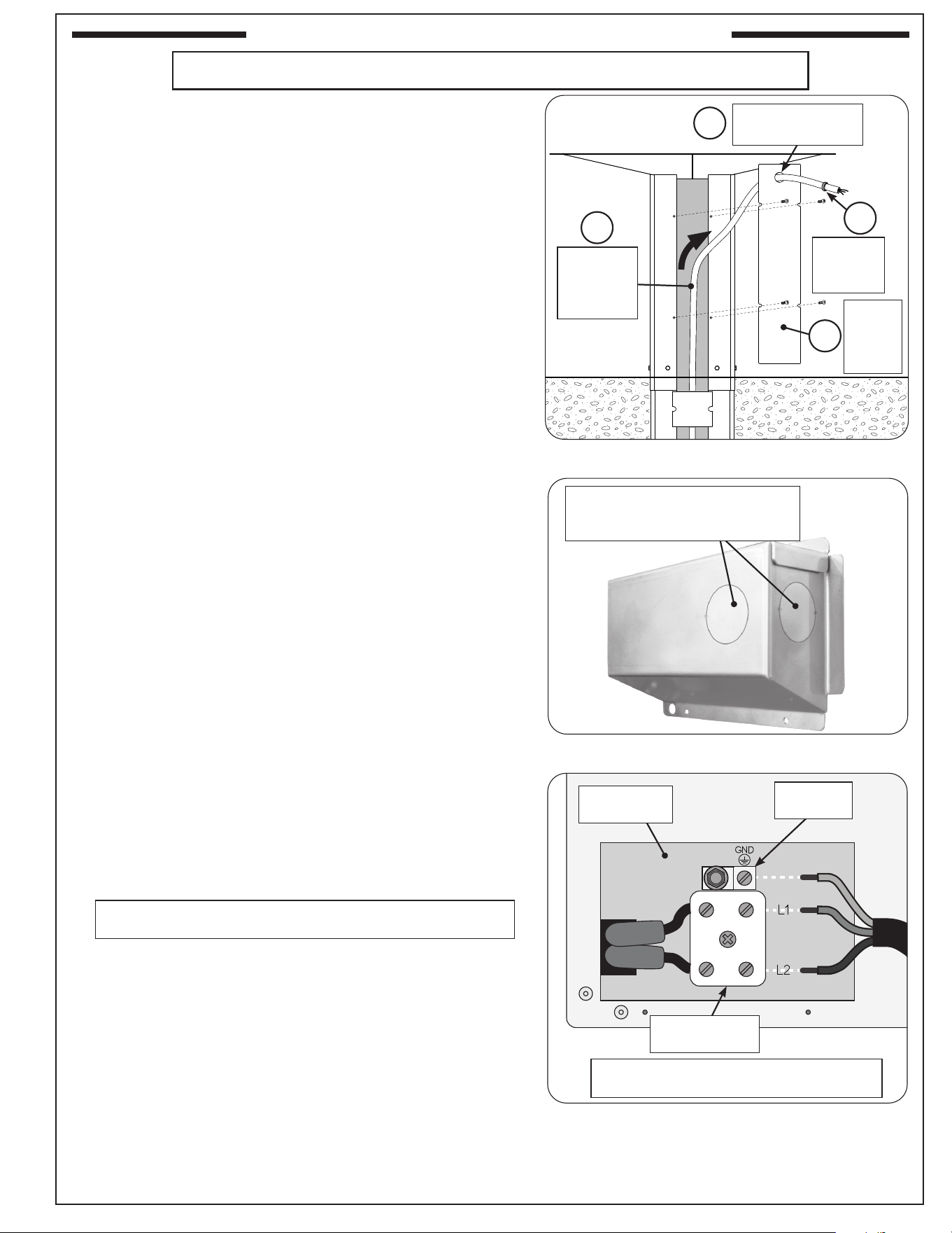
33
IN-GROUND POST INSTALLATION (CONT.)
UNDERGROUND ELECTRICAL INSTALL METHOD (CONT.)
Connect Electrical To Rear Of Electric Grill
Observe the National Electric Code and all local codes.
1. Prepare electrical for connection:
• Guide wiring up the post assembly (See Fig. 33-1, A).
• Feed the electrical through the knockout hole of the
access plate (see Fig. 33-1, B) and re-fasten the
access plate (see Fig. 33-1, C).
Note: Use one of the two knockouts as applicable for
your installation. The plastic grommet provided
is intended to be used with the inner knockout.
• Install the grommet (included) onto the electrical and
slide the grommet up against the knockout hole and
snap into place (See Fig. 33-1, D).
2. Remove the junction box located on the rear of the unit.
Select and remove a knockout from the junction box that
will best suit your electrical setup. See Fig. 33-2.
3. Take the wiring that is exiting the top portion of the
post access plate and route it through the selected
knockout opening on the junction box. Reference the
INSTALLATION OVERVIEW section for a summarized
view of this installation.
Note: Adding a non-metallic strain relief bushing to the
opening is recommended (not included).
4. Connect the wires to the ceramic terminal block. Reference
the wiring information below and Fig. 33-3.
Line 1: Connect to L1 - top portion of ceramic terminal
block
Line 2: Connect to L2 - bottom portion of ceramic terminal
block
Ground: Connect to GND (ground) - aluminum grounding
lug
5. Ensure all wire connections are fully secure, switch ON
the electrical system and test the power to the unit.
6. Secure the junction box back onto the grill.
Fig. 33-3 Wire connection diagram
Fig. 33-2 Junction box knockouts
1. Select and remove a knockout
2. Feed wires through opening
3. Make connections to unit
Proceed to the COMMON INSTALLATION section
Fig. 33-1 Remove access plate and knock-out
A
B
Guide through
knockout opening
Install
grommet
(included)
D
Route
electrical
up through
post
Re-
fasten
access
plate
C
~ 230-240
Connections / Circuit breaker rating:
230/240VAC / 30 AMP minimum / 50/60 Hz
Junction box
opening
Grounding
lug
Ceramic
terminal block
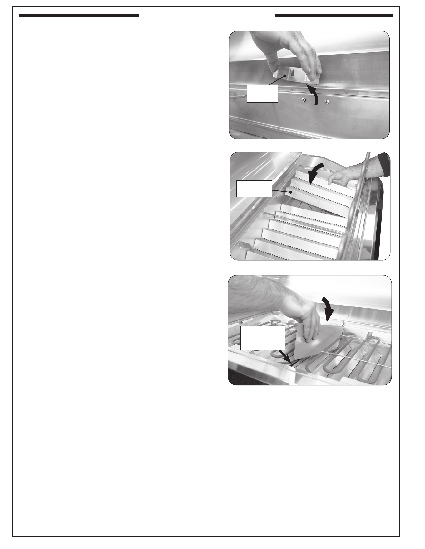
34
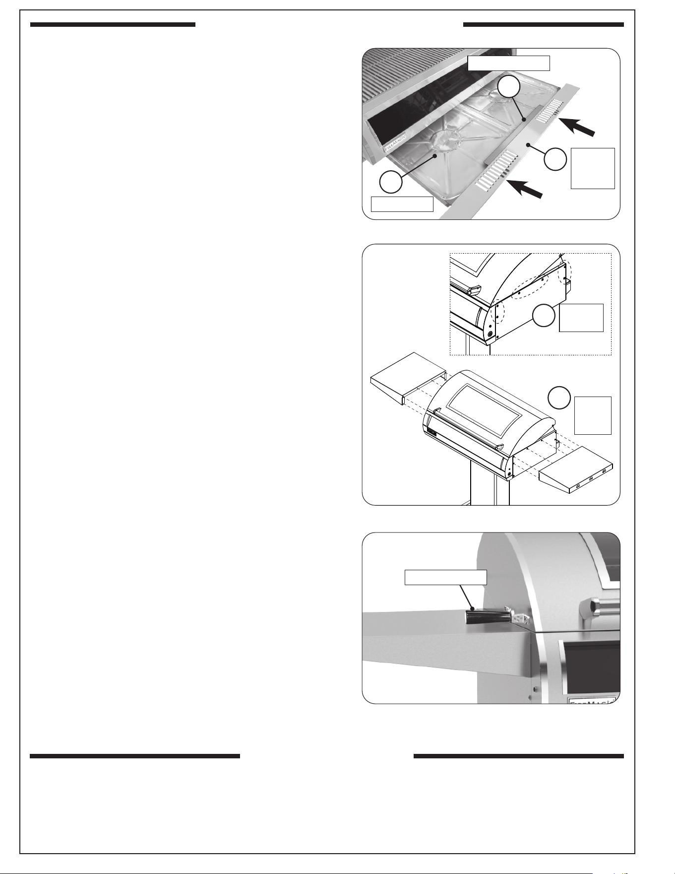
INSTALL VAPORIZER PANELS
1. Pull and swing the heating element(s) to the "up position"
by lifting the rear-end of the element up and away from
the rear support bracket.
2. Locate the rear heating element support bracket and
slightly loosen the two screws. Detach and remove the
bracket by sliding it upward. See Fig. 34-1.
Note: It is only necessary to remove one support bracket
to give clearance for vaporizer installation.
3. With the support bracket removed, carefully place the
vaporizer panels down into the electric grill as shown
in Fig. 34-2.
4. Reinstall the rear support bracket.
INSTALL ZONE DIVIDER (dual control models)
Locate the zone divider and carefully hook it over the center
wire rod as shown in Fig. 34-3.
Fig. 34-1 Remove element support bracket
Fig. 34-2 Install vaporizer panels
Support
bracket
Vaporizer
panel
COMMON INSTALLATION
Fig. 34-3 Install zone divider
Hang zone
divider from
wire rod
35
COMMON INSTALLATION (CONT.)
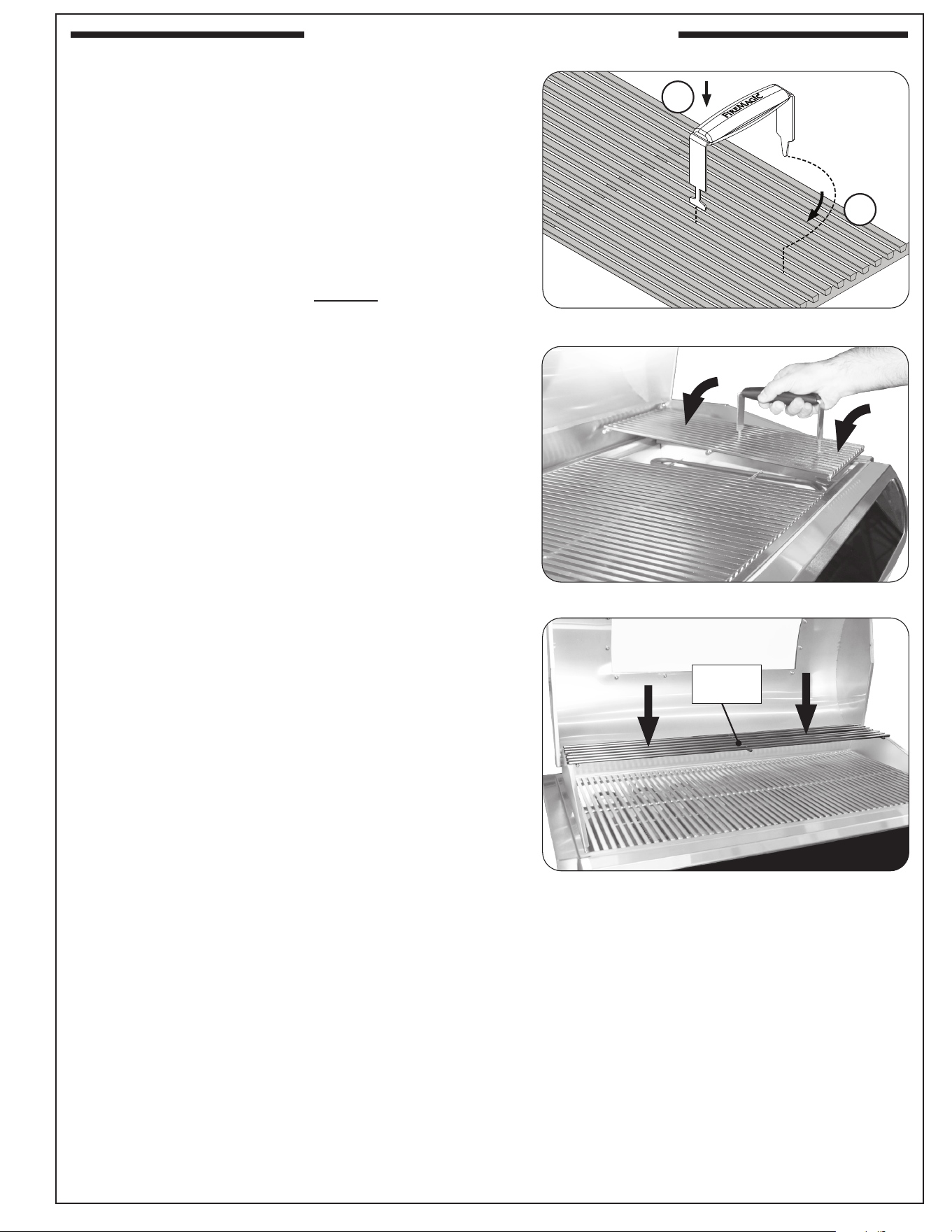
INSTALL COOKING GRIDS
Note: Wear heat-resistant gloves if necessary.
Note: Do not leave the lifter on any hot surfaces.
1. With the prongs facing downward, insert the notched-
end of the lifter between two grid rods, then rotate, as
shown in Fig. 35-1, A & B.
Note: To balance, insert the notched-end of the lifter
in the middle front half of the cooking grid.
2. Insert the rear pointed-end of the lifter between the same
two rods (Fig. 35-1, B) and carefully lift the cooking grid
and place onto the front and rear grid rests of the grill
(see Fig. 35-2). Repeat for all other cooking grids.
INSTALL WARMING RACK
Install the warming rack by carefully inserting the two feet
through the holes found on the raised walls of the unit (see
Fig. 35-3).
Fig. 35-2 Install cooking grids
Fig. 35-1 Install cooking grids
A
B
Fig. 35-3 Install warming rack
Warming
rack
36
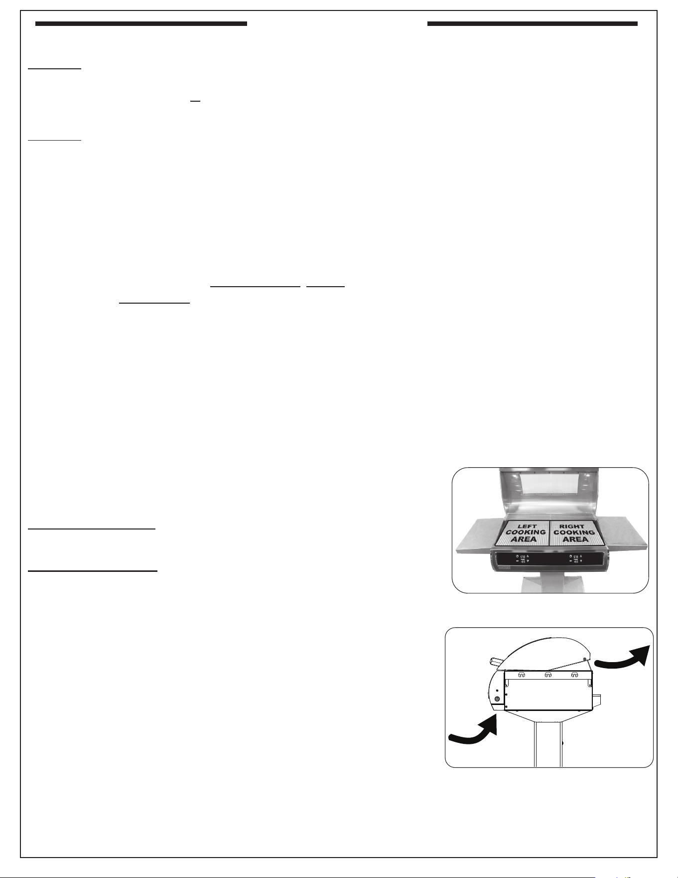
COMMON INSTALLATION (CONT.)
INSTALL DRIP TRAY
Your grill includes drip tray liners (4 pcs).
1. Take two liners and place into the drip tray . For easiest
drip tray liner installation:
• Ensure the drip tray is fully removed from the grill
• Place the liners (Fig. 36-1, A) underneath the tab at
the front portion of the drip tray (Fig. 36-1, B)
• Position the rear portion of the liner to t under the
rear lip
2. Fully insert the drip tray with liners into the bottom front
opening of the electric grill (Fig. 36-1, C).
Note: For easiest drip tray assembly installation, insert the
tray in an upward angle to clear the bearings.
INSTALL RIGID SHELVES
1. Locate and remove the Phillips-head screws shown in
Fig. 36-2, A.
2. Position a shelf against the side of the electric grill body,
aligning the holes.
3. Insert the six screws and hand-tighten slightly (see Fig.
36-2, B).
4. Once all screws are inserted and started, fully tighten
with a screwdriver.
5. Repeat the process for the other shelf.
INSTALL SIDE HANDLE KIT (AP Series Only)
AP Series Electric Grills include an oven lid side handle
kit. To install, follow the instructions included with the kit.
Reference Fig. 36-3.
After installation, perform an operation test of the grill and its features/components. Refer to the following
sections for details.
OPERATION TEST
A
Place liners
Place under tab
C
Install
drip tray
assy
Fig. 36-1 Install drip tray
B
Fig. 36-2 Install rigid shelves
Fig. 36-3 Install side handle kit (if equipped)
Side handle kit
A
Remove
screws
B
Align
and
fasten
37
BEFORE INITIAL USE
Ensure that:
• the unit has been properly installed and tested by a qualied professional service technician and as instructed in this manual.
• you have read and understand all of the information in this manual.
BEFORE EACH USE
Ensure that:
• the recommended vent openings and surrounding area of the enclosure are clear at all times.
• the cooking area and drip tray are clean, and the drip tray is properly installed.
• you inspect all electrical connections for damage, cuts, wear, and tear. Replace any damaged components prior to use.
OPERATION
• The unit (including the window glass, if equipped) becomes HOT during use. NEVER touch any part of the cooking area or
surrounding hot surfaces with bare hands. Use long-handled insulated BBQ tools and wear an insulated glove / oven mitt.
• Always keep your face and body as far from the unit as possible during use. Avoid wearing loose-tting clothing as they could
ignite.
• This appliance is designed as an attended appliance. DO NOT leave this appliance in operation when unattended.
• NEVER cover more than 75% of the cooking surface with griddles, pots or pans to prevent overheating.
• After each use, press the thermometer power button to shut o the unit.
• The unit’s fans will stay in operation, even after the unit has been turned o to quickly cool down the electronics.
Important: DO NOT CUT OFF THE UNIT FROM POWER UNTIL THE FANS SHUT OFF AUTOMATICALLY AND THE
ELECTRONICS HAVE COOLED DOWN TO A SAFE TEMPERATURE.
After reading and understanding all bullets above, follow these steps to start the heating elements and use your grill:
1. Begin heating the grill per the DIGITAL THERMOMETER / THERMOSTAT section. See the THERMOMETER/THERMOSTAT & COOKING
AREAS section below for additional details.
2. Set the element to the desired temperature (repeat for the second thermostat if applicable), close the hood, and allow the grill to preheat for at
least 15 minutes or until desired cooking temperature is reached.
3. Place the food on the grill and cook as desired. Monitor the temperature, and adjust the
heat setting if necessary.
4. See the sections below and the following pages for all other information regarding use.
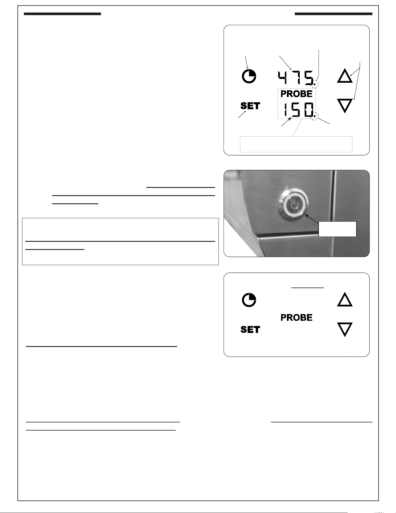
THERMOMETER/THERMOSTAT & COOKING AREAS
Models with single control: The heating element and meat probe are controlled by the glass-
touch digital thermometer/thermostat - see DIGITAL THERMOMETER/THERMOSTAT section
for operation.
Models with dual controls: Your grill is divided into two cooking areas and are controlled
independently by the two glass-touch digital thermometer/thermostats (Fig. 37-1). The left digital
thermometer controls and monitors the left heating element and left meat probe jack, and the
right digital thermometer controls and monitors the right heating element and right meat probe
jack - see DIGITAL THERMOMETER/THERMOSTAT section for operation.
WIND CONSIDERATIONS
Proper airow (front-to-back, Fig. 37-2) MUST be maintained for the unit to perform as it was
designed. See the INSTALLATION REQUIREMENTS section for details.
When using the unit in windy conditions, the wind can disrupt the airow and cause overheating.
To prevent overheating during windy conditions, do not leave the hood closed with the element(s)
on max setting for more than 15 minutes.
AFTER EACH USE
1. Operate at 700° F with hood closed for 10-15 minutes to burn o all grease.
2. Turn o the grill and brush/scrape the cooking grids to remove all residue.
CAUTION: Use long-handled insulated BBQ tools and wear an insulated glove / oven mitt.
3. When the grill is cool, check and clean the drip tray. Then cover the grill.
Note: For additional cleaning information, refer to the SERVICING AND CLEANING section.
Fig. 37-2 Airow diagram
USING THE ELECTRIC GRILL
Fig. 37-1 Cooking areas
(dual control models)
USE, CARE, & SERVICE
USING THE GRILL
38
To operate the unit via the RHP Connect app, visit the link
below or scan the QR code on the cover page of this manual
to download the app onto your mobile device and for app
operating instructions.
https://remagicgrills.com/digital-touch-control/
Important: Ensure the thermometer rmware is up to date
using the RHP Connect app.
Models with a single control are equipped with a touch-panel
controlled digital thermometer/thermostat for temperature
adjustment, meat probe temperature monitoring, and timed
cooking.
Models with dual controls are equipped with two touch-panel
controlled digital thermometer/thermostats. Each side of the
grill has a dedicated temperature control, meat probe jack for
temperature monitoring, and timed cooking.
Note: The following information provides guidance on
operating a single thermometer/thermostat. For
models with dual controls, each thermometer/
thermostat is individually controlled for each
cooking area. See USING THE ELECTRIC GRILL
section.
Read the following sections completely regarding thermometer/
thermostat operation. Refer to Fig. 38-1 for thermometer
orientation and button locations.
Power ON / OFF
The thermometer power switch is located on the right side
of the control panel (Fig. 38-2). It controls the power to the
digital thermometer/thermostat.
Press thermometer power switch to turn ON: The digital
controls will illuminate and the thermometer/thermostat will
wait in “standby mode” until turned on for use. If the meat
probe is plugged in, PROBE will also illuminate. See Fig. 38-3.
• The thermometer/thermostat must to be turned on manually via the touch controls before any functions on
the grill can be used. To turn ON, see the Turn ON Thermostat/Thermometer Functions section.
• If the unit remains in standby mode without any button presses for 10 minutes, the illuminated buttons will
turn o. To turn back on, swipe your hand across the general buttons area to illuminate the buttons.
Press thermometer power switch to turn OFF: The appliance will shut o. The power switch MUST be in
the OFF position when the grill is not in use.
• The fans will remain on to continue cooling the electronics, see OPERATION section under USING THE
GRILL section of this manual.
• To cut the grill completely from electrical power, it will need to be disconnected from the main power source
(via power cord, GFCI disconnect, or circuit breaker as applicable).
• Dual control models: To turn o ONE side of the grill (controls and heat) and keep controlling the other,
press and hold the TIMER and SET buttons (on the side you wish to turn o) until the temp. displays turn o.
Fig. 38-3 Standby mode
(Only these icons will be illuminated
when in standby mode)
Fig. 38-2 Press thermometer power switch
Thermometer
power switch
Grilling
temp.
Meat probe temp.
Fig. 38-1 Orientation (default screen)
Arrows for
adjusting
Alarm
ON
Heating
element ON
Timer
button
Set
button
Probe area only illuminates when a meat probe
is plugged into the corresponding jack
FOR OPTIMAL PERFORMANCE:
Keep the oven lid closed during cooking. This will maintain
the cooking temp. (Frequently opening or leaving the lid
open during cooking will result in greater temperature loss.)
DIGITAL THERMOMETER / THERMOSTAT
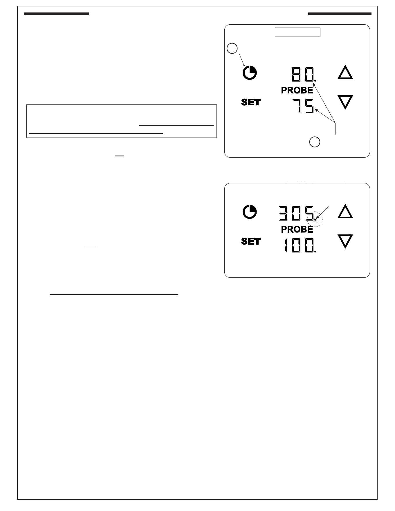
39
Turn ON Thermometer/Thermostat functions
1. Turn on the power source to the appliance.
2. Press the thermometer power switch.
3. Press and hold the TIMER button (Fig. 39-1, A) until the
remainder of the displays illuminate (Fig. 39-1, B). This is
the “default screen”. The default screen displays your
temperatures. The top display is the grilling temperature,
and the bottom display is the meat probe temperature (if
plugged in).
• The dot next to the grilling temp. indicates that the
heating element is on. The dot turns on and off
intermittently as the element maintains the set temp.
See Fig. 39-2.
• The unit automatically preheats to the default temperature
of 450° F. To set your desired temperature, see the Set
Grilling Temperature section on the following page.
• The thermometer/thermostat will automatically shut
o 4 hours from the time the thermometer/thermostat
functions are turned on. The thermometer/thermostat
sits in “idle mode” until it is turned back on for use. See
Idle Mode section for details.
• To turn o one of the thermometer/thermostats and
continue operating the other, choose the thermometer
you wish to turn o, press and hold the SET and TIMER
buttons until the temperature display turns o. The
thermometer and heating element are turned o. Press
and hold the TIMER button to turn back on if desired.
Note: Operating in cold weather conditions: If the unit is
powered on during cold weather (32° F or below) and
the TOP display reads “- - -”, Allow the unit sucient
time to preheat.The thermometer is not calibrated to
read temperatures at or below 32° F. Allow the heating
elements to warm up and the display will resume normal
functioning once the unit temp rises above 32° F.
CAUTION: ONCE THE THERMOMETER/THERMOSTAT
FUNCTIONS ARE TURNED ON, THE ELEMENT WILL
AUTOMATICALLY BEGIN TO PREHEAT!
Fig. 39-1 Turn on thermometer/thermostat
Temp displays
will illuminate
Press and hold
TIMER button
A
B
Fig. 39-2 Heating element ON
Heating element
ON
(Default screen)
DIGITAL THERMOMETER / THERMOSTAT (CONT.)
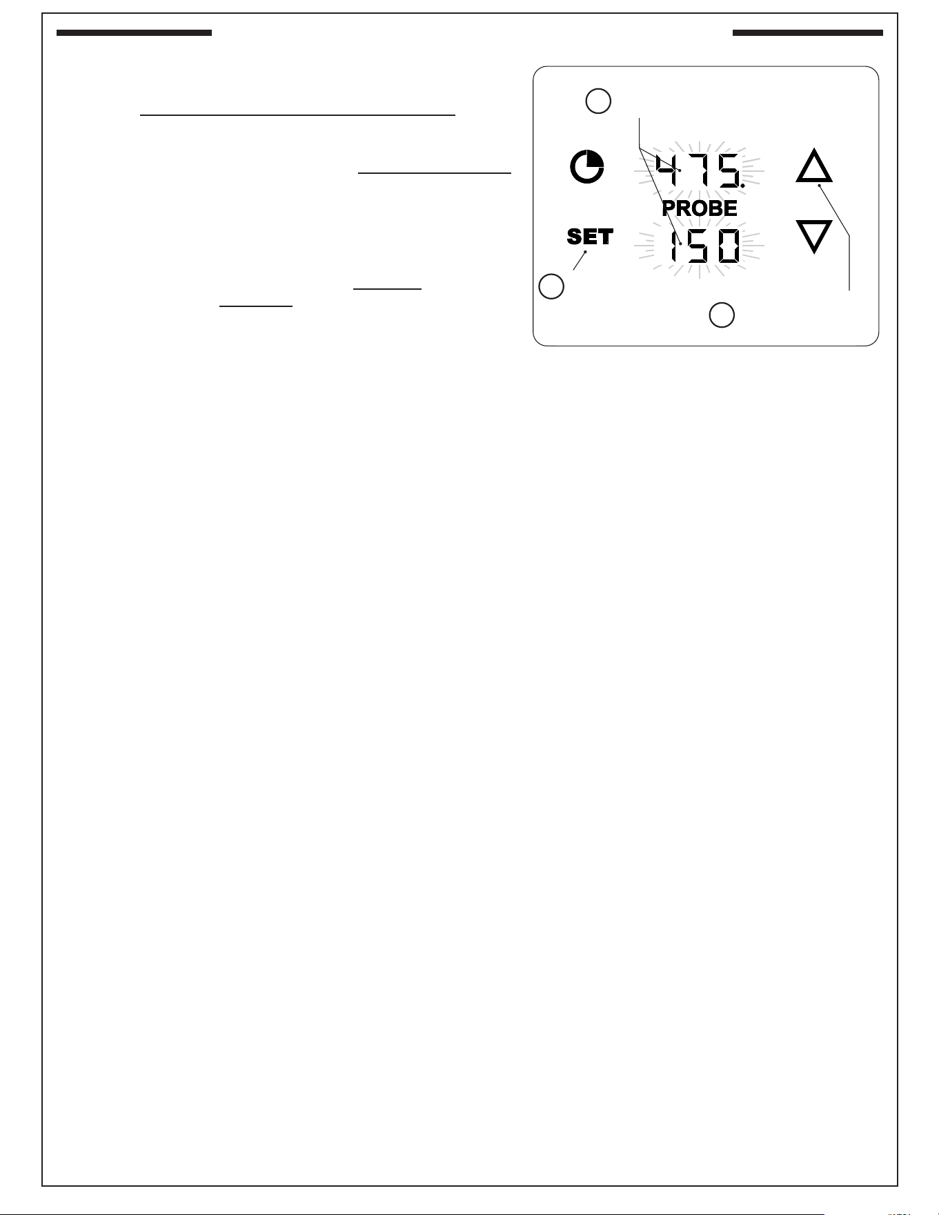
40
Fig. 40-1 Set grilling temp.
Temp displays
will BLINK
Press
SET
A
B
Press UP ARROW,
then adjust grilling temp.
using UP or DOWN
C
Set Grilling Temperature
1. With the thermometer/thermostat on, press the SET button
once. The grilling and probe displays will blink. (While
blinking, either area can be selected to enter their settings.)
See Fig. 40-1, A and B.
2. Press the UP ARROW to select the grilling temp settings,
then use the up or down arrows to set the desired temp.
(Fig. 40-1, C).
Note: Short pressing the arrows will adjust in increments of
5°. Holding down an UP or DOWN arrow (for several
seconds) will adjust the temp. rapidly.
• The default setting is 450° F. The minimum temp setting
is 200° F. The maximum temp. setting is 700° F.
Note: The grilling temp controls the temperature inside of the
grill. (This is the thermostat function.)
3. Press the SET button to conrm (or wait 5 seconds to
conrm automatically). Once conrmed it will resume to
the “default screen”.
• The temp. display will climb until it reaches the set
temperature. Once reached, the set temp will remain
displayed regardless of the actual temperature although
frequent lid opening/closing, environmental conditions,
and cold food insertion causes the temp. to uctuate, the
set temp will display the target temp. until a new temp.
is set. The element dot will remain illuminated until the
targeted temp. is reached.
DIGITAL THERMOMETER / THERMOSTAT (CONT.)
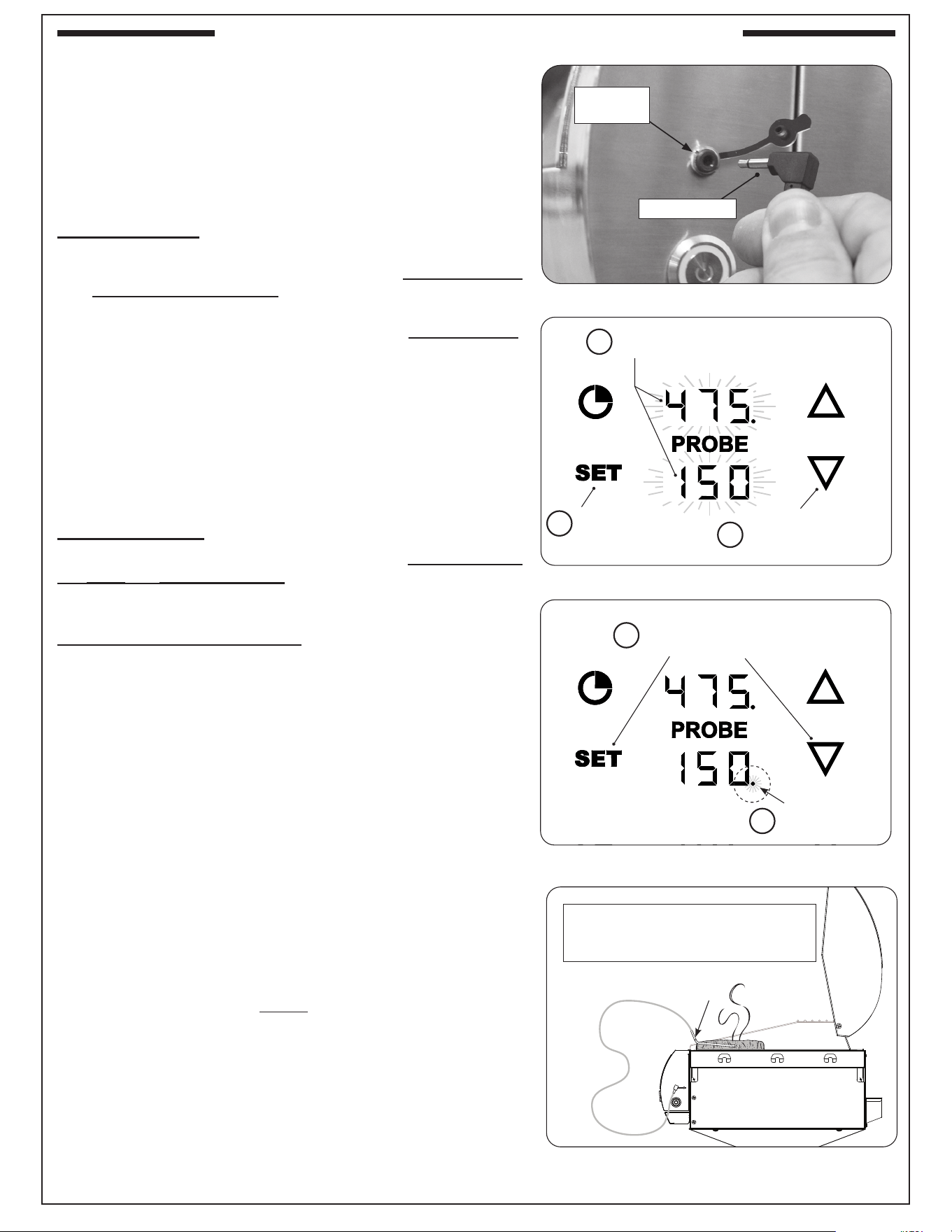
41
Fig. 41-2 Set probe temperature
Temp displays
will BLINK
Press
SET
A
B
Press DOWN ARROW,
then adjust probe temp.
using UP or DOWN
C
Fig. 41-3 Set probe alarm
Probe alarm
dot will turn on
Press and hold
SET & DOWN ARROW
A
B
Setting Meat Probe Temp. & Meat Probe Alarm
Plug the meat probe into the meat probe jack found on the right
side of the control panel as shown in Fig. 41-1. Dual control
models are equipped with two meat probe jacks (one on each
side of the control panel).
Note: The digital display does not illuminate any probe
information unless the meat probe is plugged in.
Meat probe temp:
1. With the thermometer/thermostat on and the meat probe
plugged in, press the SET button once. The grilling and
probe displays will blink. (While blinking, either area can
be selected to enter their settings.) See Fig. 41-2, A and B.
2. Press the DOWN ARROW to select the probe settings,
then you may use the up or down arrows to set the desired
temp (Fig. 41-2, C).
Note: Short pressing the arrows will adjust in increments of
1°. Holding down an UP or DOWN ARROW (for several
seconds) will adjust the temp. rapidly.
• The default probe setting is 160° F.
3. Press the SET button to conrm immediately or wait 5
seconds and it will conrm automatically. Once conrmed
it will resume to the “default screen”.
Meat probe alarm:
Once the desired probe temp. has been set, press and hold
the SET and DOWN ARROW until a dot appears next to the
PROBE temperature. The dot indicates the probe alarm is on.
See Fig. 41-3, A and B.
To disable the meat probe alarm, press and hold the SET and
DOWN ARROW until the dot disappears. The alarm is o.
• Inserting the meat probe into the cooking meat will give an
actual temp. reading. The display will ash and the alarm
will sound when the set temp. is reached.
• Press any of the four buttons to silence.
• The meat probe may be left attached to the meat for
long-term use with the oven hood closed.
• Probe tip must remain in the center of the thickest part of
the meat when in use. Leaving the meat probe protruding
through the meat while the oven hood is closed will damage
the meat probe. The probe is calibrated specically for use
at temperatures between 125˚F and 180˚F. Tip exposure
of 200˚F or more for extended time will damage probe and
it will need to be replaced.
• If wire shows visible damage, meat probe needs to be
replaced.
• Heat-resistant gloves MUST be worn when handling the
hot meat probe.
• Cleaning the meat probe under running water is permittable,
DO NOT fully submerge in water. It is NOT dishwasher-
safe.
• Meat probe must be dried completely before use.
• Meat probe must be stored in the bamboo storage box
when not in use.
Fig. 41-1 Plug in meat probe
MEAT PROBE
Meat probe
jack
Fig. 41-4 Meat probe
Meat
probe
Wear heat-resistant gloves and use
extreme caution when handling the
hot meat probe.
DIGITAL THERMOMETER / THERMOSTAT (CONT.)
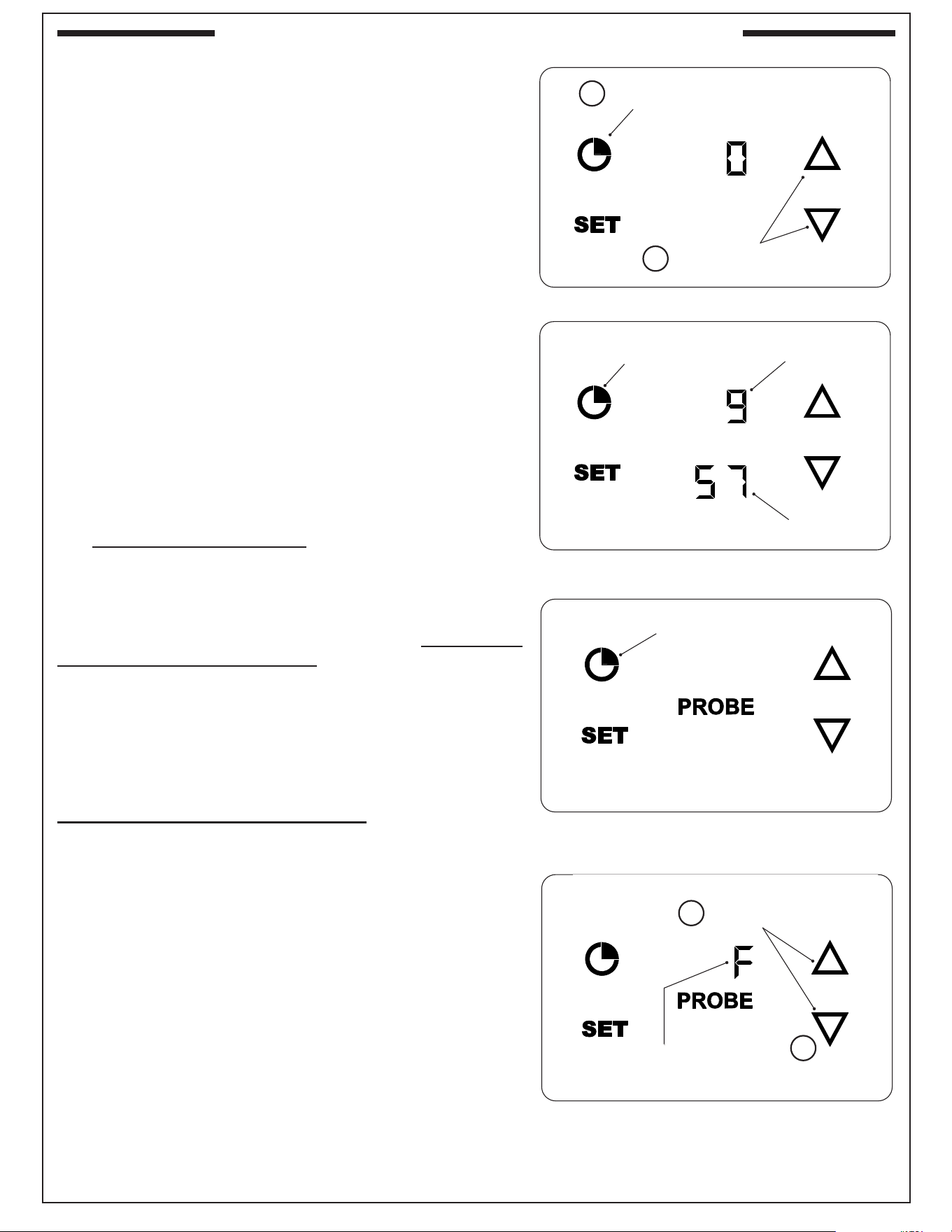
42
Setting the Timer
1. With the thermometer/thermostat on, press the TIMER
button once (Fig. 42-1, A). A zero will display indicating
that no timer is set.
2. Press the UP or DOWN arrows to enter the desired amount
of time or to modify an existing set time (Fig. 42-1, B).
Note: Short pressing the arrows will adjust in increments of
one minute. Holding down the UP or DOWN arrow (for
several seconds) will adjust the time rapidly.
3. Press the TIMER or SET button (or wait 5 seconds) to
conrm. The timer will start counting down and the display
will resume to the “default screen”.
• To check the timer status, press the TIMER button and the
display will show the live countdown (for 5 seconds then,
return to the default screen). See Fig. 42-2.
• The upper display indicates minutes and the lower display
indicates seconds (see Fig. 42-2).
• When the timer has 10 seconds left, the countdown will
display. Once the timer reaches zero the display will start
ashing and the alarm will sound.
• Press any of the four buttons to silence and return to the
“default screen”.
• To cancel an active timer: follow steps 1 and 2 above
and adjust the time down to zero.
Idle Mode
The thermometer/thermostat will automatically turn o and
enter “idle mode” after 4 hours from the time the thermometer/
thermostat functions are turned on. The heating elements and
all functions will turn o as a safety measure.
Similar to “standby mode”, idle mode screen appears the
same with the controls illuminated (Fig. 42-3), but this mode also
memorizes your last settings used (as long as the thermometer
power switch remains on). This will allow you to resume right
where you left o.
To exit idle mode and resume grilling: press and hold the
SET TIMER button until the remainder of the displays illuminate.
See Fig. 42-3. The displays will fully illuminate and the heating
element will turn back on.
Note: If the unit remains in idle mode without any button
presses for 10 minutes, the illuminated buttons will
turn o. To turn back on, swipe your hand across the
general button area to illuminate the buttons.
Changing Temperature Unit
1. Press and hold the UP and DOWN arrows until °F or °C is
displayed (Fig. 42-4, A).
2. Press the UP or DOWN arrow to select the desired temp
unit (Fig. 42-4, B).
3. Press SET (or wait 5 seconds) to conrm. The display will
return to the default screen with the newly set temperature
unit.
Fig. 42-3 Idle mode
Fig. 42-4 Change temp. unit
Use arrows to enter
desired temp. unit
(Fahrenheit unit
shown here)
Press and hold
UP & DOWN ARROWS
A
B
Fig. 42-1 Set timer
Use arrows to enter
desired amount of time
Press TIMER
button
A
B
Fig. 42-2 Check timer status
(Minutes)
(Seconds)
Press TIMER to
see status
To resume grilling, Press and
hold TIMER button
(Only these icons will be illuminated
when in idle mode)
DIGITAL THERMOMETER / THERMOSTAT (CONT.)
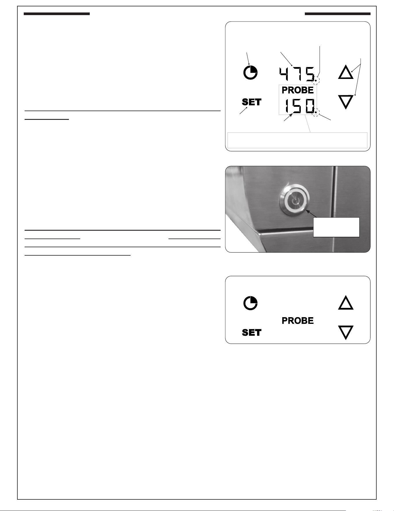
43
Lisez intégralement les sections suivantes concernant le
fonctionnement du thermomètre/thermostat. Référez-vous à la
Fig. 43-1 pour l’orientation du thermomètre et l’emplacement
des boutons.
COMMENT METTRE EN MARCHE ET ÉTEINDRE
L’interrupteur d’alimentation du thermomètre se trouve sur
le côté droit du panneau de commande (Fig. 43-2). Il contrôle
l’alimentation du thermomètre/thermostat numérique.
Appuyez sur l’interrupteur d’alimentation du thermomètre
pour allumer: Les commandes numériques s’allumeront, et
le thermomètre/thermostat restera en mode veille jusqu’à son
activation pour une utilisation. Si la sonde à viande est branchée,
PROBE s’allumera également. Voir Fig. 43-3.
• Le thermomètre/thermostat doit être activé manuellement
via les commandes tactiles avant de pouvoir utiliser les
fonctions du gril. Pour l’allumer, consultez la section ‘Activer
les fonctions du thermostat/thermomètre’.
• Si l’appareil reste en mode veille sans aucune pression
de bouton pendant 10 minutes, les boutons éclairés
s’éteindront. Pour les rallumer, passez votre main sur la
zone générale des boutons pour les illuminer.
Appuyez sur l’interrupteur d’alimentation du thermomètre
pour éteindre.: L’appareil s’éteindra. L’interrupteur
d’alimentation DOIT être en position OFF lorsque le gril
n’est pas en cours d’utilisation.
• Les ventilateurs resteront en marche pour continuer à
refroidir l’électronique, voir la section ‘OPERATION’ sous
la section ‘USING THE GRILL’ de ce manuel.
• Pour couper complètement l’alimentation électrique du gril, il
devra être déconnecté de la source d’alimentation principale
(via le cordon d’alimentation, la déconnexion GFCI, ou le
disjoncteur, selon le cas).
• Modèles de contrôle double: Pour éteindre UN côté du
gril (commandes et chaleur) tout en continuant à contrôler
l’autre, appuyez et maintenez enfoncés les boutons TIMER
et SET (du côté que vous souhaitez éteindre) jusqu’à ce
que les achages de température s’éteignent.
Température
de grillage
Température de la
sonde à viande
Fig. 43-1 Orientation (écran par défaut)
Fig. 43-2 Appuyez sur l’interrupteur
du thermomètre
Fig. 43-3 Mode veille
Flèches pour
ajuster
(Seuls ces icônes seront éclairés en mode veille)
Alarme
ACTIVÉE
Élément
chauant
ALLUMÉ
Bouton de
minuterie
Bouton de
réglage
Interrupteur
d’alimentation du
thermomètre
La zone de la sonde s’illumine uniquement lorsque la sonde
à viande est branchée dans la prise correspondante.
THERMOMÈTRE NUMÉRIQUE / THERMOSTAT
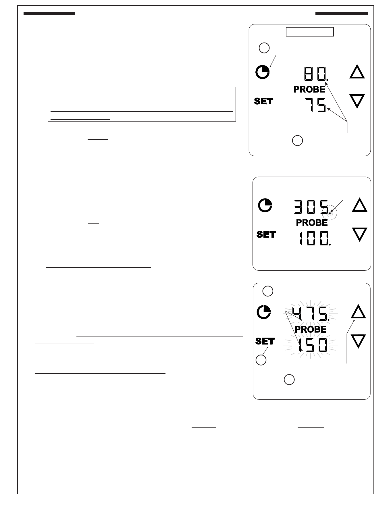
44
Fig. 44-1 Turn on thermometer/
Thermostat
Les achages de
température s’illumineront
Appuyez et maintenez
enfoncé le bouton TIMER
A
B
Fig. 44-2 Élément chauant ACTIVÉ
Élément chauant
ACTIVÉ
(Écran par défaut)
Fig. 44-3 Réglez température cuisson
Les achages de
température clignoteront
Appuyez
sur SET
A
B
C
Appuyez sur la FLÈCHE
VERS LE HAUT, puis ajustez
la température de cuisson en
utilisant les touches VERS LE
HAUT ou VERS LE BAS
Activer Les Fonctions Du Thermomètre/Thermostat
1. Allumez la source d’alimentation de l’appareil.
2. Appuyez sur l’interrupteur d’alimentation du thermomètre.
3. Appuyez et maintenez enfoncé le bouton TIMER (Fig. 44-1, A) jusqu’à
ce que le reste des achages s’allume (Fig. 44-1, B). Il s’agit de l’écran
par défaut. L’écran par défaut ache vos températures. L’achage
supérieur est la température de cuisson, et l’achage inférieur est la
température de la sonde à viande (si elle est branchée).
• Le point à côté de la température de cuisson indique que l’élément
chauant est activé. Le point s’allume et s’éteint de manière
intermittente lorsque l’élément maintient la température réglée.
Voir Fig. 44-2.
• L’unité préchaue automatiquement à la température par défaut de
450 °F. Pour régler la température souhaitée, consultez la section
‘Réglage de la température de cuisson’ ci-dessous.
• Le thermomètre/thermostat s’éteindra automatiquement 2 heures
après que les fonctions du thermomètre/thermostat sont activées.
Le thermomètre/thermostat reste en ‘mode veille’ jusqu’à ce qu’il
soit à nouveau activé pour une utilisation. Consultez la section
Mode veille pour plus de détails.
• Pour éteindre l’un des thermomètres/thermostats et continuer à
utiliser l’autre, sélectionnez le thermomètre que vous souhaitez
éteindre, appuyez et maintenez les boutons SET et TIMER jusqu’à
ce que l’achage de la température s’éteigne. Le thermomètre et
l’élément chauant sont éteints. Appuyez et maintenez le bouton
TIMER pour le réactiver si nécessaire.
Note: Fonctionnement par temps froid: Si l’unité est allumée par temps
froid (32 °F ou moins) et que l’achage SUPÉRIEUR indique ‘- -
-’, laissez à l’unité susamment de temps pour préchauer. Le
thermomètre n’est pas calibré pour lire les températures à 32 °F
ou en dessous. Laissez les éléments chauants se réchauer,
et l’achage reprendra un fonctionnement normal une fois que
la température de l’unité dépassera 32 °F.
Réglage De La Température De Cuisson
1. Avec le thermomètre/thermostat allumé, appuyez une fois sur le
bouton SET. Les achages de la température de cuisson et de la
sonde clignoteront. (Pendant le clignotement, n’importe quelle zone
peut être sélectionnée pour entrer dans ses réglages.) Voir Fig. 44-3,
A et B.
2. Appuyez sur la FLÈCHE VERS LE HAUT pour sélectionner les
paramètres de la température de cuisson, puis utilisez les èches
vers le haut ou vers le bas pour régler la température souhaitée.
(Fig. 44-3, C).
Note: Appuyer brièvement sur les èches ajustera par incréments de
5°. Maintenir enfoncé une FLÈCHE VERS LE HAUT ou VERS
LE BAS (pendant plusieurs secondes) ajustera rapidement la
température.
• Le réglage par défaut est de 450 °F. Le réglage minimal est de 200 °F. Le réglage maximal est de 700 °F.
Note: La température de cuisson contrôle la température à l’intérieur du gril. (Il s’agit de la fonction du thermostat)
3. Appuyez sur le bouton SET pour conrmer (ou attendez 5 secondes pour une conrmation automatique). Une
fois conrmé, l’écran reviendra à l’écran par défaut.
• L’achage de la température augmentera jusqu’à atteindre la température réglée. Une fois atteinte, la
température réglée restera achée, indépendamment de la température réelle (bien que l’ouverture/
frermeture fréquente du couvercle, les conditions environnementales et l’insertion d’aliments froids puissent
faire uctuer la température, la température réglée achera la température cible jusqu’à ce qu’une nouvelle
température soit réglée). Le point de l’élément restera allumé jusqu’à ce que la température cible soit atteinte.
CAUTION: UNE FOIS QUE LES FONCTIONS DU
THERMOMÈTRE/THERMOSTAT SONT ACTIVÉES,
L’ÉLÉMENT COMMENCERA AUTOMATIQUEMENT À
PRÉCHAUFFER !
THERMOMÈTRE NUMÉRIQUE / THERMOSTAT (suite)
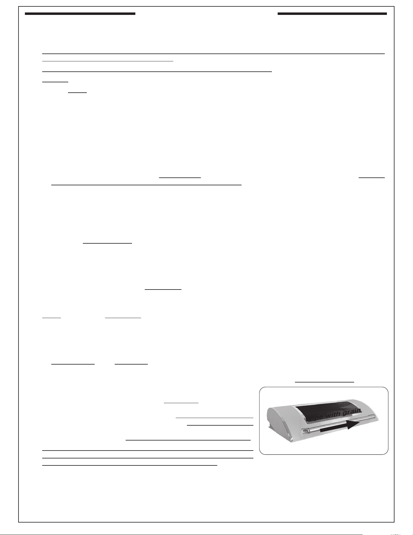
45
SERVICING AND CLEANING
Your electric grill requires regular cleaning and maintenance. Refer to these instructions for details. Performing these
procedures will ensure proper operation, appearance, and safety.
WARNINGS
• Prior to servicing or cleaning make sure the unit is completely cool, the unit is o, and the power supply is disconnected
(as applicable and unless otherwise stated).
• Wear appropriate gloves and safety glasses during any servicing or cleaning.
• DO NOT spray any cleaner or liquids on the unit when hot.
• The unit MUST be cleaned regularly to prevent grease build-up and other food deposits. A clean and well maintained
unit prevents the risk of grease build-up and grease res.
• Verify proper operation after servicing or deep cleaning.
• See IMPORTANT SAFEGUARDS section for additional related information.
CLEANING YOUR ELECTRIC GRILL
Before Each Use
1. Inspect and clean the exterior surfaces of the unit: With a cool grill, clean any dust, grease, splatter, or spills as
needed with a damp clean cloth.
2. Clean the glass:
• Clean the glass control panel with a non-abrasive quality brand glass cleaner and a clean gentle cloth. DO NOT
use other cleaners or chemicals to prevent scratching the glass.
• Clean the Magic View Window (interior and exterior) with a quality brand glass cleaner and clean cloth.
After Each Use
1. Clean the cooking grids: Operate at 700° F with hood closed for 10-15 minutes to burn o all grease. Turn o the
grill and brush/scrape the cooking grids to remove all residue. Use long-handled insulated BBQ tools and wear an
insulated glove / oven mitt.
Important: The cooking element is self-cleaning (it does not require manual cleaning).
2. Check and clean your drip tray: When the unit is cool, carefully remove the drip tray and dispose of contents
appropriately. If tray is equipped with a liner, dispose of the liner. Clean tray in a soapy water solution if needed. For
tough deposits, a copper pad can be used. Rinse and dry completely. Replace a new liner and insert the tray back
into the electric grill. Order more drip tray liners through your dealer.
3. Cover your grill: Once the unit is dry and cool, cover your grill with a Fire Magic protective cover (not included).
Twice A Year (or as needed) - Deep Clean
1. Interior of grill: In addition to cleaning the cooking grids and drip tray, a deep clean of the interior and all components
MUST be performed twice a year (or as needed depending on use). Follow the steps below.
a. With a cool unit, open the oven lid and remove the cooking grids and inner liners. Clean all components in a soapy
water solution, rinse, dry, and set aside. For tough deposits, a copper pad can be used. The components can also
be cleaned in a dishwasher.
Note: Refer to the parts list and INNER LINER REMOVAL section as needed.
b. Grill inner walls: use a grill cleaner and a copper pad to scrub the inner walls. Fire Magic grill cleaner is recommended.
Follow instructions provided with the grill cleaner.
Wipe down the entire surface of the inner walls with a wet, clean, heavy-duty rag. Remove all cleaner.
c. Re-install all components removed during this process.
2. Exterior of grill: With a cool grill, use a grill cleaner (or a soapy water
solution) and a clean cloth to remove grease and dirt from the grill exterior.
For tough deposits, a copper pad can be used. Always wipe with the grain.
Rinse and dry completely. Then follow up with a stainless steel cleaner
and a clean cloth. To clean the magic view window (if equipped), use a
quality brand glass cleaner. DO NOT use other cleaners or chemicals.
If this routine cleaning is not performed, the stainless steel may become
dull and develop surface rust (due to use and atmospheric conditions).
If left uncleaned, signicant damage and pitting may occur.
Important: DO NOT use steel wool, any other metal tools, or any other cleaners/chemicals to clean the exterior other
than recommended above. Such items promote rust.
Note: Due to the nature of stainless steel, temperatures produced by the cooking process will cause discoloration. This
can be reduced by routine cleaning.
3. Glass surfaces: For hard water stains on glass, it is recommended to clean the glass using a white vinegar / water
solution and wiping clean with a soft cloth.
Wipe with grain
Fig. 45-1 Wipe with grain

46
For Environments High In Salt, Chloride, Or Other Corrosive Chemicals
When this grill is installed in a corrosive environment such as near the ocean (salt air), poolside (chlorine and/or
pool chemicals) or any other location with exposure to high salt/chloride content or corrosive chemicals/solutions,
it will be more susceptible to corrosion and MUST be maintained/cleaned more frequently.
• DO NOT store any corrosive chemicals (chlorine, hydrochloric acid, fertilizer, etc.) near your stainless steel unit.
• DO NOT allow any corrosive materials (masonry dust, debris, etc.) to settle on your stainless steel unit.
• These environments, chemicals, and materials may cause the 304 stainless steel to develop surface rust and
consequently pitting. Under these conditions the unit exterior MUST be cleaned at least monthly. Inspect your grill
often and clean accordingly.
Protecting Your Electric Grill
An optional Fire Magic protective cover will protect your grill when not in use. Install the cover on a cool and dry unit. DO
NOT cover a damp grill. During high humidity or after rainy conditions, remove the cover to dry trapped moisture if present.
(If the cover is installed over a damp unit it can cause surface rust.)
Ensure that the INSIDE of the cover is DRY before putting it back on the grill.
SERVICING AND CLEANING (Cont.)
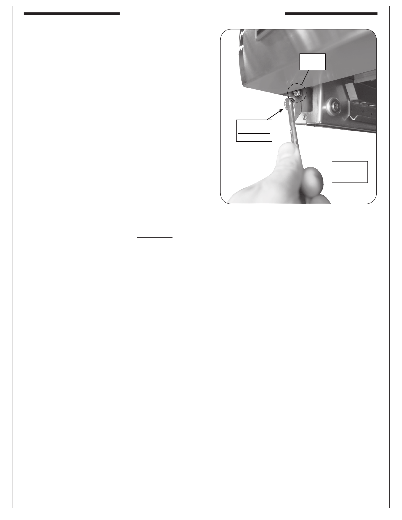
47
CONTROL PANEL REMOVAL
The interior of the control panel must only be accessed
by a qualied professional service technician.
1. Ensure the grill is completely cool and the
power to the unit is disconnected.
2. Slide the drip tray outward partially to allow enough
room to access the control panel securing nuts.
3. Loosen the nuts underneath the left and right sides
of the control panel with a
11
/
32
" wrench (see Fig.
47-1), then lift the panel until it is freed from the
screws. Carefully rest the bottom of the control
panel on the drip tray. The top of the control panel
is supported by the internal chains.
Important: When opening, take caution to not
damage any wiring.
4. If wire disconnections are required, reference the
wire diagram in the MODEL SPECIFICATIONS
section in this instruction manual or the wire diagram
label axed to the inside of the control panel.
Note: Whenever reconnecting any wires, apply a
small amount of dielectric grease to the male
connector, then make the connection. This will
ensure conductivity and prevent moisture from
aecting the contact.
Fig. 47-1 Remove control panel
Loosen
nuts
11
/32"
Closed-end
wrench
(Drip tray
removed for
clarity)
SERVICING AND CLEANING (Cont.)

48
NOTES PAGE
Please use this page to record any information about your unit that you may want to have at hand.

49
If you have trouble with the unit, please use this list to identify the problem. By trying one or more of the solutions
to the possible cause, you should be able to solve the problem. If this list does not cover your present problem,
or if you have other technical diculties with the unit, please contact your local dealer.
PROBLEM POSSIBLE CAUSE CORRECTION
Grill does not work
1. Power failure 1. Check if power is available.
2. Power not connected properly 2. Make sure the power source and powering
equipment is properly connected and tested.
3. Thermostat switch protection
engaged
3. Electronics overheated and activated
thermostat switch. A qualied professional
service technician must reset the thermal
switch and inspect the unit thoroughly.
4. GFCI or circuit breaker may be
tripped
4. Reset GFCI or circuit breaker.
Thermometer/
thermostat does not
work
1. No power to unit 1. Ensure power is available.
2. Unit timed-out after 2 hrs (idle mode) 2. Swipe hand over controls to illuminate buttons
and power on thermometer/thermostat.
3. Faulty thermometer/thermostat 3. Contact your dealer.
4. Display reads: OH 4. The PCB board overheated. Cause may be
due to wind entering rear of lid, or grease re.
Allow to cool and turn back on. Check fans are
working properly. If still no function, contact your
local dealer.
5. Display reads: Err 5. Thermocouple disconnected or faulty. Check
connection or replace if faulty.
6. Probe display reads: - - - 6. Meat probe temp. exceeded limit. Let cool
and retry, if still not functioning call dealer to
replace.
Cooking element
does not work
1. No power to unit 1. Ensure power is available.
2. Bad element 2. Contact your dealer.
TROUBLESHOOTING
50
R.H. Peterson Co. • 14724 East Proctor Avenue • City of Industry, CA 91746
Quality Check
Date:______________
Electrical Leak Test: __________________________
Operation Test: __________________________
Inspector: __________________________
Model #:
Serial #:
A COPY OF YOUR SALES SLIP FOR PROOF OF PURCHASE IS REQUIRED
This warranty applies to the original purchaser for products which are installed in the United States or Canada and which are operated and maintained as
intended for single family residential usage (if the unit is installed in a commercial / multi-user setting, a separate Commercial / Multi-User Limited Warranty
applies and is available from RHP). This warranty is valid only with proof of purchase, commences on the date of purchase, and terminates (both as to original
and any replacement products) on the anniversary date of the original purchase of the product per the above schedules.
This warranty does not cover parts which become defective as a result of negligence, misuse, or use not in compliance with the Installation and Owner’s Manual,
accidental damage, improper handling, improper storage, improper installation, lack of required routine maintenance (as specied in the Installation and
Owner’s Manual), or electrical damage. Product must be installed as specied in the Installation and Owner’s Manual by a qualied professional installer.
This warranty does not apply to normal occurrences that may be expected with any outdoor product such as rust, corrosion, oxidation, or discoloration unless
the aected part becomes inoperable. RHP products including heating elements and controls are designed and certied to be used as a system. Modications
to products which are not specically authorized will void this warranty and could render the product to be unsafe. Heating elements, controls,Burners, valves,
parts, remotes, accessories, etc. used with this product must be RHP products or this warranty is void.
Warrantied items will be repaired or replaced at RHP's sole discretion. This warranty does not cover labor or labor related charges, except as provided by
separate specic written programs from RHP. All repair work must be performed by a qualied professional service person and requires prior approval of RHP.
RHP may require the defective product or part to be returned to the factory to determine the cause of failure. RHP will pay freight charges if the product or part
is determined to be defective. This warranty does not cover breakage in shipment from our independent distributor to its customer if the damage is determined
to have occurred during that shipment.
This warranty specically excludes liability for indirect, incidental, or consequential damages. Some states and provinces do not allow the exclusion or
limitation of incidental or consequential damages, so the above exclusion may not apply to you. This warranty gives you specied legal rights, and you may
have other rights that vary from state to state or province.
For additional information regarding this warranty, or to place a warranty claim, contact the RHP dealer where the product was purchased.
When contacting your RHP dealer or the R.H. Peterson Co., please provide the following information:
- Your name, address, telephone number, e-mail
- Sales receipt showing where purchased and date purchased
- Model number, serial number of product, date code
- Relevant information: installer, additions, repairs, when defect was rst noted
TO REGISTER YOUR PRODUCT ONLINE GO TO: WWW.RHPETERSON.COM,
AND CLICK ON PRODUCT REGISTRATION. THANK YOU FOR YOUR PURCHASE.
PETERSON FIRE MAGIC GRILLS AND ACCESSORIES
LIMITED WARRANTY
R.H. Peterson Co. ("RHP") warrants your Fire Magic
®
grill to be free from defects in material and workmanship.
Fire Magic cast stainless-steel gas burners, Choice stainless steel U shaped burners, cooking grids, and Barbecue and vent hood housings are
warranted as long as the original purchaser owns them -- LIFETIME. (Except as described below.)
Fire Magic brass valves, manifold assemblies, inner liners, porcelain housings (including ovens and barbecue faces), and backburner assemblies
(except ignition systems) are warranted for FIFTEEN (15) YEARS.
Fire Magic built-in pizza ovens and griddles (except ignition system and thermostat) are warranted for TEN (10) YEARS.
Fire Magic heating elements, Infra-red burners, avor grids, and charcoal stainless steel grills are warranted for FIVE (5) YEARS; except for the
charcoal pan, charcoal grid, analog thermometer, and ash catch tray, which are warranted for ONE (1) YEAR.
Fire Magic side burners, induction cooktops, exterior Glass Fiber Reinforced Concrete (GFRC) grill island systems, and all other grill, vent hood,
pizza oven and griddle components (except ignition systems and electronic parts) are warranted for THREE (3) YEARS.
Fire Magic Echelon gas grill, pizza oven and EL500 electric grill under glass touch screen electronic controls are warranted for TWO (2) YEARS.
Fire Magic grill, pizza oven and griddle ignition systems (excluding batteries), electronic components (including lights, digital thermometers and
thermostats) and accessories are warranted for ONE (1) YEAR.
WARRANTY