A WARNING!
Some dust created by power sanding, sawing, grinding, drilling, and
other construction activities contains chemicals known to the State
of California to cause cancer, birth defects or other reproductive
harm. Some examples of these chemicals are:
•
Lead from lead-based paints.
•
Crystalline silica from bricks, cement and other masonry products.
•
Arsenic and chromium from chemically-treated lumber.
Your risk from these exposures varies, depending on how often you
do this type of work. To reduce your exposure to these chemicals:
Work in a well ventilated area, and work with approved safety equip
ment, such as those dust masks that are specially designed to filter
out microscopic particles.
Symptom
Workpiece surface
is marred or
scratched.
Workpiece does
not move through
wheels without
excessive force.
Workpiece curve is
too high.
Workpiece curve is
not high enough.
Workpiece curve will
not form.
Workpiece has
wrinkles.
Possible Cause
Possible Solution
1. Too much wheel pressure. 1. Reduce wheel pressure.
2. Wheels are diy. 2. Clean and protect all wheel surfaces (see Page 16).
1. Too much wheel pressure. 1. Reduce wheel pressure.
2 Wheel bearings at fault. 2. Replace wheel bearings.
1. Lower wheel radius is too great.
1. Use a lower wheel with less radius (crown).
1. Lower wheel radius is not enough. 1. Start with lower wheel of least radius and work up to
correct radius for the operation.
1. Not enough wheel pressure. 1. Gradually increase wheel pressure.
2. Lower wheel has flat suace. 2. Use lower wheel(s) with a radius (crown).
1. Tracking pattern at fault. 1. Use a consistent and smooth tracking pattern that
overlaps with each back-and-foh pass.
2. Too much wheel pressure. 2. Start with least amount of pressure, then gradually
increase pressure when the curve stops forming.
-17-
TROUBLESOOTING
MACHINE DATA
SHEET
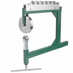
MODEL 61088
English Wheel Metal Shaping Benchtop
Product Dimensions:
Weight ............................................................................................................................................................................. 18 lbs.
Width (side-to-side)/Depth (front-to-back)/Height ....................................................................................... 1" x 23¼" x 19
1
16"
Shipping Dimensions:
Type ................................................................................................................................................................... Cardboard Box
Content. ...................................................................................................................................................................... Equipment
Weight .............................................................................................................................................................................. 30 lbs.
Width/Depth/Height ............................................................................................................................................... 2" x 21" x 25"
Overall Dimensions:
Number of Upper Wheels ......................................................................................................................................................... 1
Upper Wheel Diameter ......................................................................................................................................... 149mm (5a'')
Upper Wheel Contour ........................................................................................................................................................... Flat
Number of Lower Wheels ......................................................................................................................................................... 7
Lower Wheel Diameters ............................................................................................................................................. 50mm (2")
Lower Wheel Contours ........................................ Flat, ½" Radius, 1" Radius, 1 ½" Radius, 2½" Radius, 5" Radius, 9" Radius
Throat ................................................................................................................................................................................. 15%"
Main Specifications:
Capacity ..................................................................................................................... 16 Gauge Mild Steel, Aluminum, Copper
Construction
Frame ........................................................................................................................................................... Steel Tubing
Wheels ...................................................................................................................................................... Hardened Steel
Paint ......................................................................................................................................................... Powder Coated
Other Specifications:
Country Of Origin .............................................................................................................................................................. China
Warranty ........................................................................................................................................................................... 1 Year
Assembly Time ......................................................................................................................................................... 10 Minutes
Features:
-4-
Quick-Release Lever
Bench Mounted
1 Upper Wheel, 7 Lower Wheels
Wheel Storage Rack
&WARNING
Damage to your eyes, hands and feet could
result from using this tool without proper
protective gear. Always wear safety glasses,
leather gloves, and steel toe footwear when
operating this tool.
NOTICE
If you are not experienced with this type
of machine, WE STRONGLY RECOMMEND
that you seek additional training outside of
this manual. Read books/magazines or get
formal training before beginning any proj
ects. Regardless of the content in this sec
tion, Stark Tools will not be held liable
for accidents caused by lack of training.
Tracking Tips
•
Stretching metal into a curve should be a
gradual process.a lwaysstart withjustenough
wheel pressure to prevent the workpiece from
skipping or slipping through the wheel fter
the initial curve has formed, increase the
pressure slightly and continue stretching the
metal. r epeat this process until the desired
curve is attained. using too much pressure
will damage the workpiece surface and pro
duce poor results.
•
Start with the lower wheel that has the least
radius (crown), then increase the wheel radi
us a step at a time until the desired curve is
reached.
•
Practice with a scrap piece that is the same
material and thickness as the final operation.
•
Leave a frame around the workpiece of
approximately 1" that does not go through
the wheels. as the center of the workpiece
stretches and the frame does not, the metal
is forced to bend into a curve.
•
Take your time. Many passes through the
wheels with gradual increases in pressure
and lower wheel radii will produce good
results and reduce the risk of damaging the
workpiece surface.
•
Overlap each pass with the previous one in
a back-and-forth, smooth movement through
the wheels. t here are many patterns of
tracking that will produce different results.
Choosing the correct pattern for your opera
tion is a matter of research and experience.
-13-
OPERATION
SPECIFICATIONS
&WARNING
WEARING PROPER APPAREL. Do not wear
clothing, apparel or jewel that can become
entangled in moving parts. Always tie back or
cover long hair. Wear non-slip footwear to avoid
accidental slips, which could cause loss of work
piece control.
HAZARDOUS DUST. Dust created while using
machine may cause cancer, birth defects, or
long-term respiratory damage. Be aware of dust
hazards associated with each workpiece material,
and always wear a NIOSH-approved respirator to
reduce your risk.
HEARING PROTECTION. Always wear hear
ing protection when operating or obseing loud
machinery. Extended exposure to this noise
without hearing protection can cause permanent
hearing loss.
REMOVE ADJUSTING TOOLS. Tools left on
machinery can become dangerous projectiles
upon startup. Never leave chuck keys, wrenches,
or any other tools on machine. Always verify
removal before starting!
INTENDED USAGE. Only use machine for its
intended purpose and never make modifications
not approved by Grizzly. Modifying machine or
using it differently than intended may result in
malfunction or mechanical failure that can lead to
serious personal inju or death!
AWKWARD POSITIONS. Keep proper footing
and balance at all times when operating machine.
Do not overreach! Avoid awkward hand positions
that make workpiece control difficult or increase
the risk of accidental inju.
CHILDREN & BYSTANDERS. Keep children and
bystanders at a safe distance from the work area.
Stop using machine if they become a distraction.
GUARDS & COVERS. Guards and covers reduce
accidental contact with moving parts or flying
debris. Make sure they are properly installed,
undamaged, and working correctly.
-6-
FORCING MACHINERY. Do not force machine.
It will do the job safer and better at the rate for
which it was designed.
NEVER STAND ON MACHINE. Serious inju
may occur if machine is tipped or if the cutting
tool is unintentionally contacted.
STABLE MACHINE. Unexpected movement dur
ing operation greatly increases risk of inju or
loss of control. Before starting, verify machine is
stable and mobile base (if used) is locked.
USE RECOMMENDED ACCESSORIES. Consult
this owner's manual or the manufacturer for rec
ommended accessories. Using improper acces
sories will increase the risk of serious injury.
UNATTENDED OPERATION. To reduce the
risk of accidental inju, turn machine OFF and
ensure all moving parts completely stop before
walking away. Never leave machine running
while unattended.
MAINTAIN WITH CARE. Follow all maintenance
instructions and lubrication schedules to keep
machine in good working condition. A machine
that is improperly maintained could malfunction,
leading to serious personal inju or death.
CHECK DAMAGED PARTS. Regularly inspect
machine for any condition that may affect safe
operation. Immediately repair or replace damaged
or mis-adjusted parts before operating machine.
MAINTAIN POWER CORDS. When disconnect
ing cord-connected machines from power, grab
and pull the plug-NOT the cord. Pulling the cord
may damage the wires inside. Do not handle
cord/plug with wet hands. Avoid cord damage by
keeping it away from heated surfaces, high traffic
areas, harsh chemicals, and wet/damp locations.
3.
Lay the frame down flat and thread the lower
wheel adjustment screw into the frame oppo
site the wheel bracket (see Fi
g
ure 6
)
.
Adjustment
P
·
Screw
Wheel
Bracket
Fi
g
ure 6. Lower wheel adjustment screw
installed.
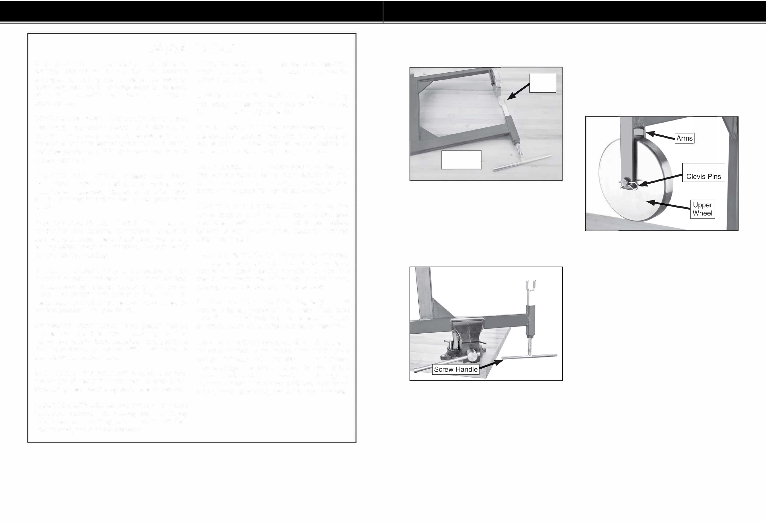
4. Secure the assembly into the bench-mounted
vise, as described on the previous page.
Note: Make sure the adjustment screw han
dle has enough cleance from the bench to
fully rotate (see gure 7).
Fi
g
ure 7. Adequate clearance to fully rotate
adjustment screw handle.
5.
Position the upper wheel between the frame
arms, insert the upper wheel clevis pin through
the arms and wheel, and secure the pin with
the hairpin cotter pin (see Fi
g
ure 8
)
.
Note: If the cotter pin does not easily slide
into the clevis pin hole, insert it as far as you
can and use a small hammer to tap it the rest
of the way.
Cotter &
Fi
g
ure 8. Upper wheel installed.
Continued on next page -�►�
-11-
OPERATION
SAFETY WARNINGS
Unpacking
Your machine was carefully packaged for safe
transportation. Remove the packaging materials
from around your machine and inspect it.
Save the containers and all packing materials for
possible inspection by the carrier or its agent.
Otherwise, filing a ight claim can be dicult.
When you are completely satisfied with the condi
tion of your shipment, inventory the contents.
&WARNING
SUFFOCATION HAZARD!
Keep children and pets away
from plastic bags or packing
materials
shipped
with
this
, ..
machine. Discard immediately.
,
-8-
Needed for Setup
The following are needed to complete the setup
process, but are not included with your machine.
Description
Qty
•
Small Hammer ............................................ 1
•
Wrench or Socket 12mm ............................ 1
•
Wrench or Socket 14mm ............................ 1
•
Vise Secured to Workbench ...................... 1
•
Sturdy Workbench ..................................... 1
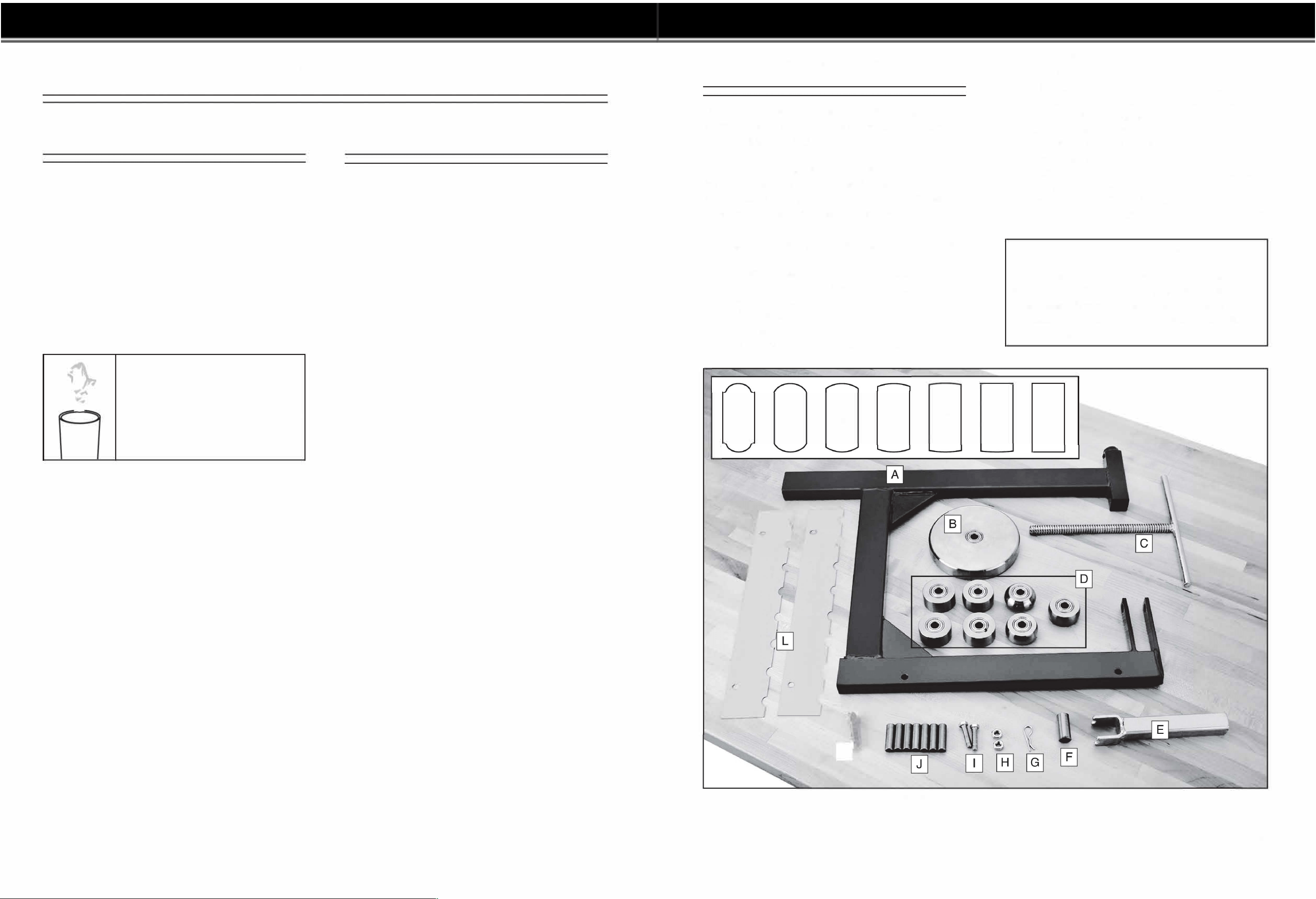
Inventory
The following is a description of the main compo
nents shipped with your machine. Lay the compo
nents out to inventory them.
If any non-proprietary parts are missing
(
e.g. a
nut or a washer
)
, we will gladly replace them; or
for the sake of expediency, replacements can be
obtained at your local hardware store.
Shipping Inventory: (Figure 2)
Qty
A. Frame ......................................................... 1
B.
Upper Wheel .............................................. 1
C.
Lower Wheel Ad
j
usting Screw .................... 1
D. Lower Wheels ............................................. 1
-½" Radius ............................................... 1
-1" Radius ................................................. 1
-1 ½" Radius ............................................. 1
½"
1"
)
)
(
'
1
½
"
2
½
"
5"
r
J
9"
-2½" Radius ............................................. 1
-5" Radius ................................................ 1
-9" Radius ................................................ 1
-Flat .......................................................... 1
E. Lower Wheel Bracket ................................. 1
F.
Bracket Spacer Rod ................................... 1
G.
Hairpin Cotter Pin %" x 1s" ....................... 1
H. Hex Nuts ¼"-20 .......................................... 2
I.
Hex Bolts ¼"-20 x 1 ¼" ............................... 2
J.
Lower Wheel Axle Rods ............................. 7
K.
Upper Wheel Clevis Pin ............................. 1
L.
Wheel Storage Racks ................................. 2
NOTICE
If you cannot find an item on this list, care
fully check the machine and the packaging
materials. Some of these items may be pre
installed for shipping or become misplaced
during unpacking.
Flat
Figure 2. Model 61088
-9-
SETTING UP
PACKAGE CONTENTS
Workbench
Mounting
The forces exerted on the English wheel during
operation are substantial. The English wheel must
be firmly secured in a vise
(
see Figure 3 for an
example
)
that is solidly attached to a workbench
or table that will support the weight and dynamic
pressures of the operation.
Make sure that you have a wobench and vise
setup for the English Wheel before performing
the Assembly instructions. Refer to Page 15 for
options.
Note: Use pieces of cardboard or wood between
the se ja and the frame to prevent frame dam
age.
Figure 3. Example of Model 61088 secured in
vise mounted to a workbench.
&CAUTION
Make sure the workbench that the English
wheel will be mounted on is stable and
can support the weight of the tool, the
workpiece, and the forces exerted during
operation.
-10-
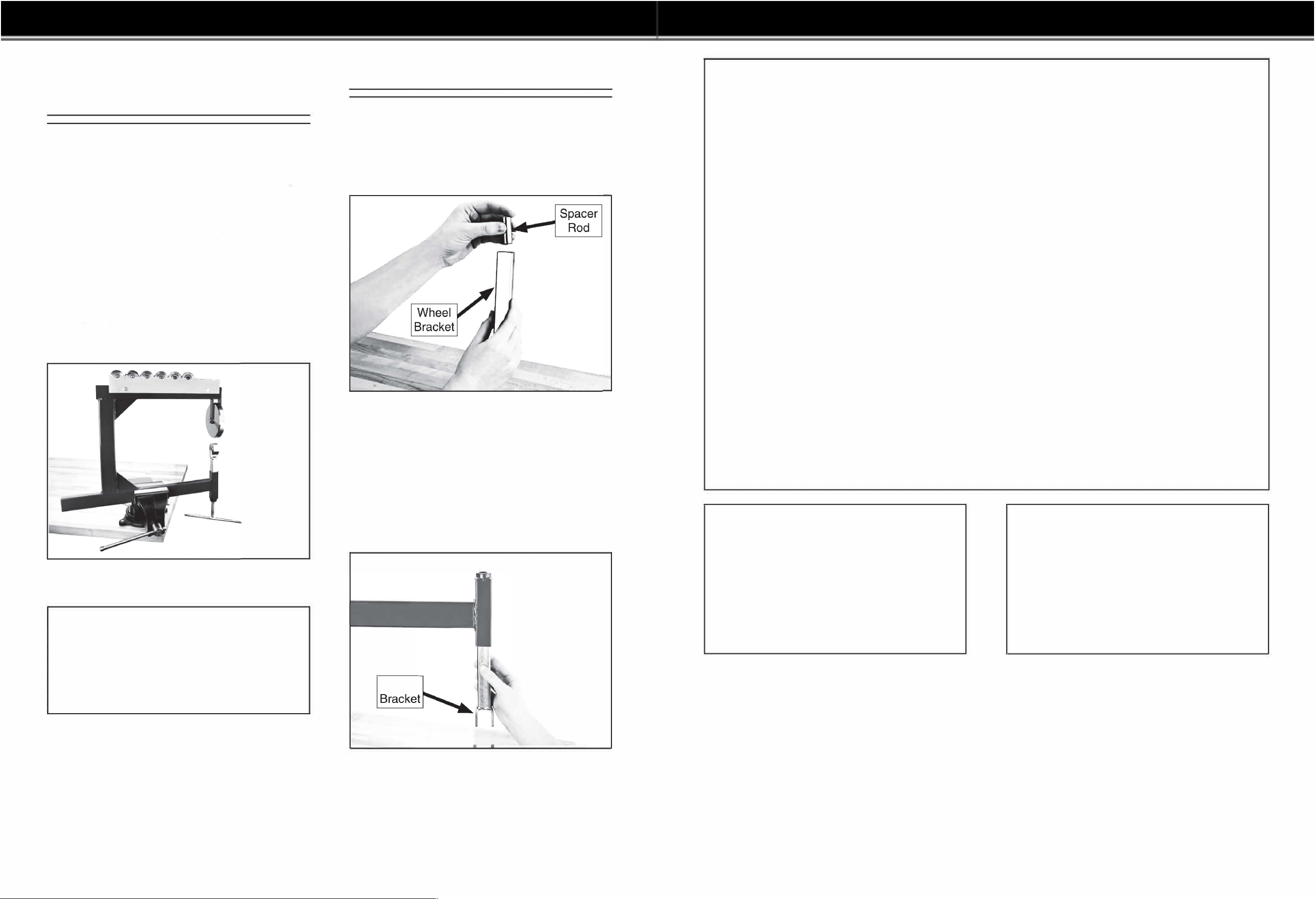
Assembly
To assemble the English wheel:
1.
Insert the bracket spacer rod into the bot
tom of the lower wheel bracket, as shown in
Figure 4.
Figure 4. Inserting spacer rod into wheel
bracket.
2.
Turn the frame upside down and inse the
lower wheel bracket into the frame, as shown
in Figure 5.
Note: Inserting the wheel bracket into the
frame when it is upside down will keep the
spacer d inside the bcket.
Wheel
Figure 5. Inserting wheel bracket into frame.
RNING
Additional Safety for English Wheel
Metal Shaping Benchtop
METAL EDGES. t he sharp edges of sheet metal
can quickly cut your ngers or hands. always wear
Reavy leather gloves when handling sheet metal.
lways chamfer and deburr sharp metal edges
�
efore inserting them into the English wheel.
INCHING HAZARD. t he rolling momentum of
the wheels can pull your ngers between them
resulting in pinching injuries. always keep your
hands away from the wheel path when moving the
�
orkpiece through the wheels.
RUSHING HAZARD. if the heavy wheels or
frame should unexpectedly fall, crushing injuries
could result. always make sure the frame is
rmly secured to a bench-mounted vise that can
properly support the weight and pressures of the
operation. Make sure the wheels are properly
installed on the support brackets or storage rack.
Wear steel-toed boots.
&WARNING
Like all machinery there is potential danger
when operating this machine. Accidents
are frequently caused by lack of familiarity
or failure to pay attention. Use this machine
with respect and caution to decrease the
risk of operator injury. If normal safety pre
cautions are overlooked or ignored, seri
ous personal injury may occur.
TOOL INSPECTION. using the English wheel
with excessively worn or damaged parts could
cause the tool to fail and present in
j
ury hazards,
as well as yield poor results. always inspect each
part of the English wheel before beginning opera
tions.
TOOL USAGE. t his English wheel was designed
only to form curves in sheet metal material such
as steel or aluminum. Do not attempt to process
any other material (e.g., glass, ceramic, plastic,
etc.) that could result in material or tool breakage.
Do not modify this tool in any way and do not
exceed the capacity of 16 gauge sheet metal.
BODY POSITION. I osing your balance while
tracking could result in impact injuries or lacera
tion injuries from the sheet metal. Make sure your
body and footing are balanced and in a good posi
tion to support your movement and momentum
while tracking.
&CAUTION
No list of safety guidelines can be com
plete. Every shop environment is different.
Always consider safety first, as it applies
to your individual working conditions. Use
this and other machinery with caution and
respect. Failure to do so could result in
serious personal injury, damage to equip
ment, or poor work results.
-7-
ASSEMBLY
WARNINGS
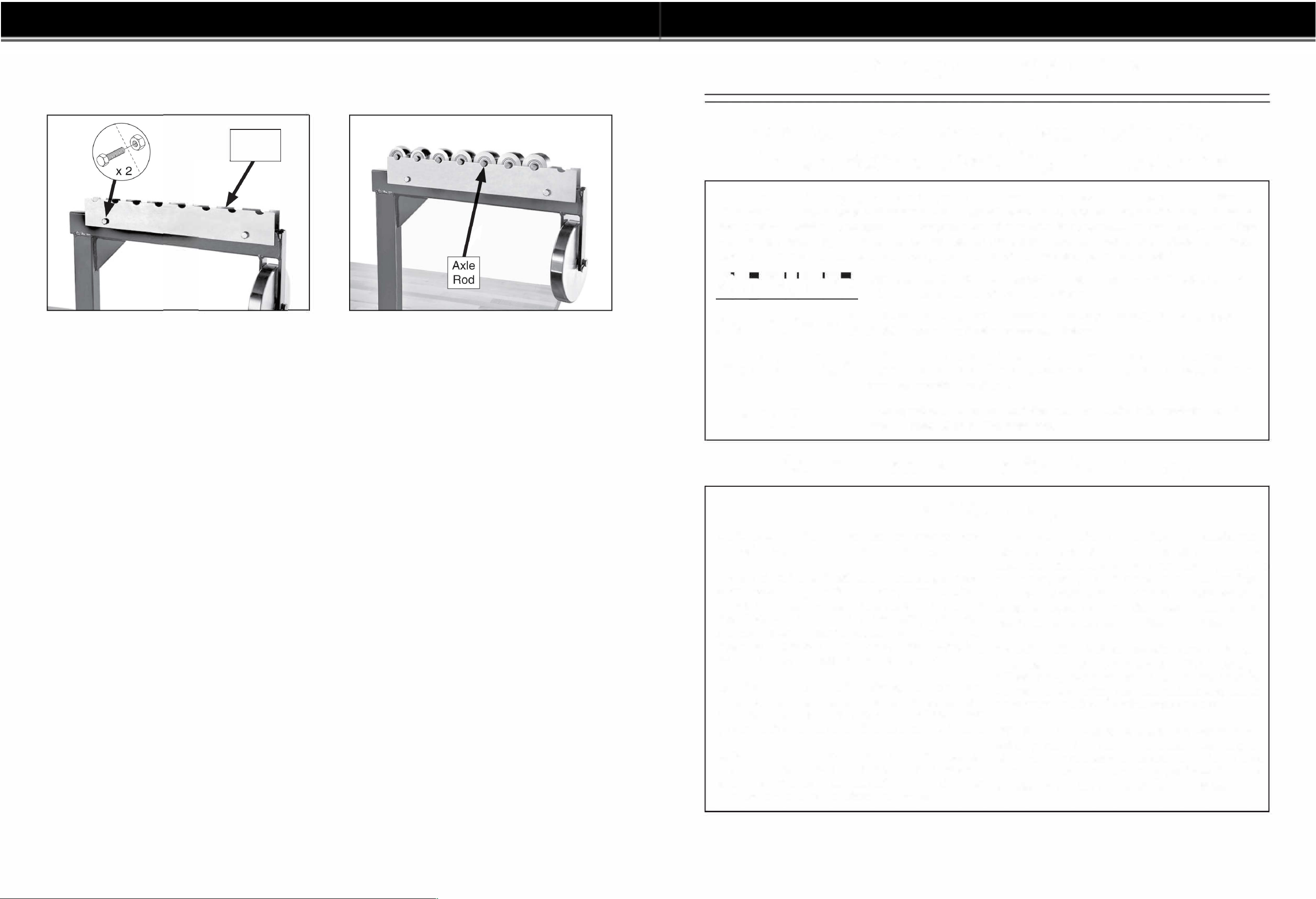
6.
Attach the lower wheel storage racks to the
frame top with (2) ¼"-20 x 1 ¼" hex bolts and
(2) ¼"-20 hex nuts (see Figure 9).
-12-
Storage
Racks
Figure 9. Storage racks installed.
7.
Insert a lower wheel axle rod into each lower
wheel, then place the assemblies on the
wheel storage racks (see Figure 10).
Figure 10. Lower wheel assemblies on wheel
storage racks.
For Your Own Safety, Read Instruction
Manual Before Operating This Machine
The purpose of safety symbols is to attract your attention to possible hazardous conditions.
This manual uses a series of symbols and signal words intended to convey the level of impor
tance of the safety messages. The progression of symbols is described below. Remember that
safety messages by themselves do not eliminate danger and are not a substitute for proper
accident prevention measures. Always use common sense and good judgment.
r1� ,,� � i1
&WARNING
Indicates an imminently hazardous situation which, if not avoided,
WILL result in death or serious injury.
Indicates a potentially hazardous situation which, if not avoided,
COULD result in death or serious injury.
&CAUTION
Indicates a potentially hazardous situation which, if not avoided,
MAY result in minor or moderate injury. It may also be used to alert
against unsafe practices.
NOTICE
This symbol is used to alert the user to useful information about
proper operation of the machine.
Safety Instructions for Machinery
&WARNING
OWNER'S MANUAL. read and understand this
owner' s manual BEForE using machine.
TRAINED OPERATORS ONLY. untrained oper
ators have a higher risk of being hurt or killed.
only allow trained/supervised people to use this
machine. When machine is not being used, dis
connect power, remove switch keys, or lock-out
machine to prevent unauthorized use-especially
around children. Make workshop kid proof!
DANGEROUS ENVIRONMENTS. Do not use
machinery in areas that are wet, cluttered, or have
poor lighting. operating machinery in these areas
greatly increases the risk of accidents and injury.
MENTAL ALERTNESS REQUIRED. Full mental
alertness is required for safe operation of machin
ery. never operate under the influence of drugs or
alcohol, when tired, or when distracted.
ELECTRICAL EQUIPMENT INJURY RISKS. you
can be shocked, burned, or killed by touching live
electrical components or improperly grounded
machinery. reduce this risk, only allow qualified
service personnel to do electrical installation or
repair work, and always disconnect power before
accessing or exposing electrical equipment.
DISCONNECT POWER FIRST. always discon
nect machine from power supply BEForE making
adjustments,changing tooling,orservicing machine.
this prevents an injury risk from unintended startup
or contact with live electrical components.
EYE PROTECTION. always wear ansi-approved
safety glasses or a face shield when operating or
observing machinery to reduce the risk of eye
injury or blindness from flying particles. Everyday
eyeglasses are not approved safety glasses.
-5-
ASSEMBLY
SAFETY WARNINGS
Basic Operations
The individual results from using an English wheel
are countless. Practice, read books/internet sites,
watch videos, and seek advice from experienced
wheelers to gain necessary knowledge and expe
rience to produce good results.
The procedure below is an example of a very
basic operation.
To use the English wheel:
1. Make sure the frame is firmly secured in a
bench-mounted vise that is solidly attached
to a bench or table that will support the
weight and pressures of the operation.
2.
Put on safety glasses, leather gloves, and
steel-toed boots.
3. Deburr the sharp edges of the workpiece
(see Accessories on Page 15 for an optional
deburring tool).
4. Mark a frame around the workpiece of approx
imately 1 ".
5.
Clean the wheels to remove any abrasive
material that could damage the surfaces of
the workpiece or wheels.
6.
Install the lower wheel with the least radius
(crown).
7.
Use the lower wheel adjustment screw to
raise the lower wheel up, leaving enough
room to insert the workpiece between the
wheels.
8.
Insert the workpiece between the wheels and
adjust the lower wheel so that the wheel pres
sure is just enough to prevent the workpiece
from skipping or slipping through the wheels.
-14
-
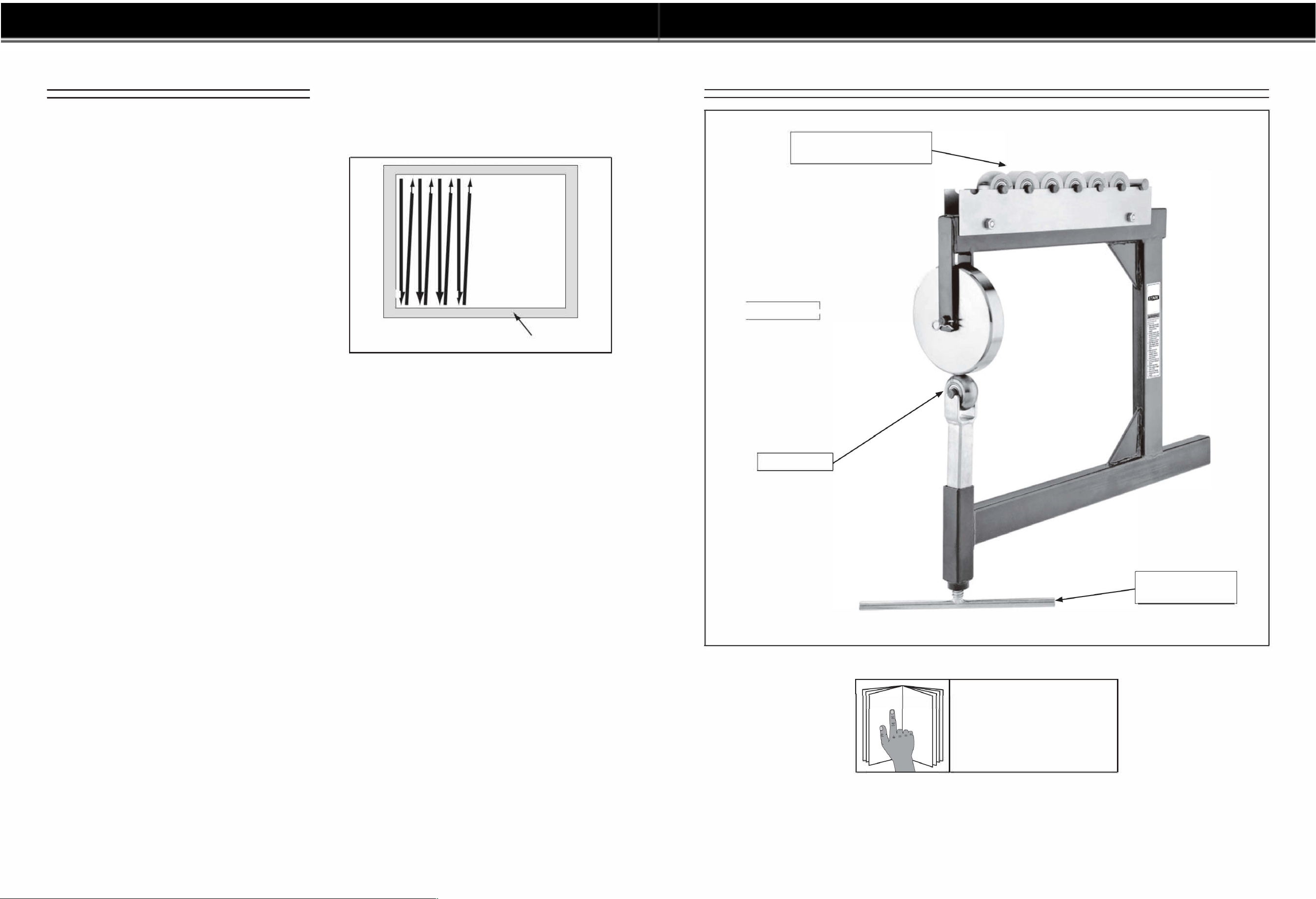
6.
Move the workpiece back and forth through
the wheels in an overlapping pattern (see
example in Figure 11 ).
Note: is example is just one of many pat
tes of tracking.
J l
J l
J l
J l
. .. and so on
11 1
Frame
Figure 11. Example of basic back-and-forth
tracking pattern.
7. When the workpiece no longer stretches,
rotate the lower wheel adjustment screw
clockwise to slightly increase the pressure.
8.
When maximum wheel pressure is reached
and the workpiece no long moves through the
wheels, change the lower wheel to the next
highest radius.
9.
Repeat Steps 5-8 until the desired curve is
attained.
Addition al Lo wer Wheels
& Storage Rack
/
I
Upper Wheel
1
-----•
Lower Wheel
Figure 1. Model 61088
&WARNING
To reduce your risk of
serious injury, read this
entire manual BEFORE
using machine.
Lower Wheel
Adjustment Screw
-3-
OPERATION
PARTS INFORMATION

Schedule
For optimum performance from your tool, follow
this maintenance schedule and refer to any spe
cific instructions given in this section.
Daily Check:
•
Damaged wheels.
•
Damaged or cracked frame.
•
Any other unsafe condition.
Daily Maintenance:
•
Clean and protect wheels.
-16-
Cleaning &
Protecting
Use clean shop rags to clean all wheel surfaces
and the wheel axle rods. Apply a metal protectant
(see Page 15), then wipe off any excess to leave
a thin coat.
Lubrication
The wheel bearings are factory lubricated and
sealed, and do not require lubrication. Merely
leave them alone unless they need replacement.
Periodically, remove the lower wheel adjustment
screw and wipe the threads with a lightly-oiled
shop rag.
INTRODUCTION ............................................................................................................................... 2
Machine Description ................................................................................................................... 2
Contact Info ................................................................................................................................ 2
Manual Accuracy ........................................................................................................................ 2
Identification ............................................................................................................................... 3
Machine Data Sheet. .................................................................................................................. 4
SECTION 1 : SAFETY ....................................................................................................................... 5
Safety Instructions for Machinery ............................................................................................... 5
Additional Safety for English Wheels ......................................................................................... 7
SECTION 2: SETUP ......................................................................................................................... 8
Unpacking .................................................................................................................................. 8
Needed for Setup ....................................................................................................................... 8
Inventory ..................................................................................................................................... 9
Workbench Mounting ............................................................................................................... 1 O
Assembly .................................................................................................................................. 1 O
SECTION 3: OPERATIONS ........................................................................................................... 13
Tracking Tips ............................................................................................................................ 13
Basic Operations ...................................................................................................................... 14
SECTION 4: ACCESSORIES ......................................................................................................... 15
SECTION 5: MAINTENANCE ......................................................................................................... 16
Schedule .................................................................................................................................. 16
Cleaning & Protecting .............................................................................................................. 16
Lubrication ................................................................................................................................ 16
SECTION 6: SERVICE ................................................................................................................... 17
Troubleshooting ........................................................................................................................ 17
SECTION 7: PARTS ....................................................................................................................... 18
MAINTENANCE
TABLE OF CONTENTS
-
2
-
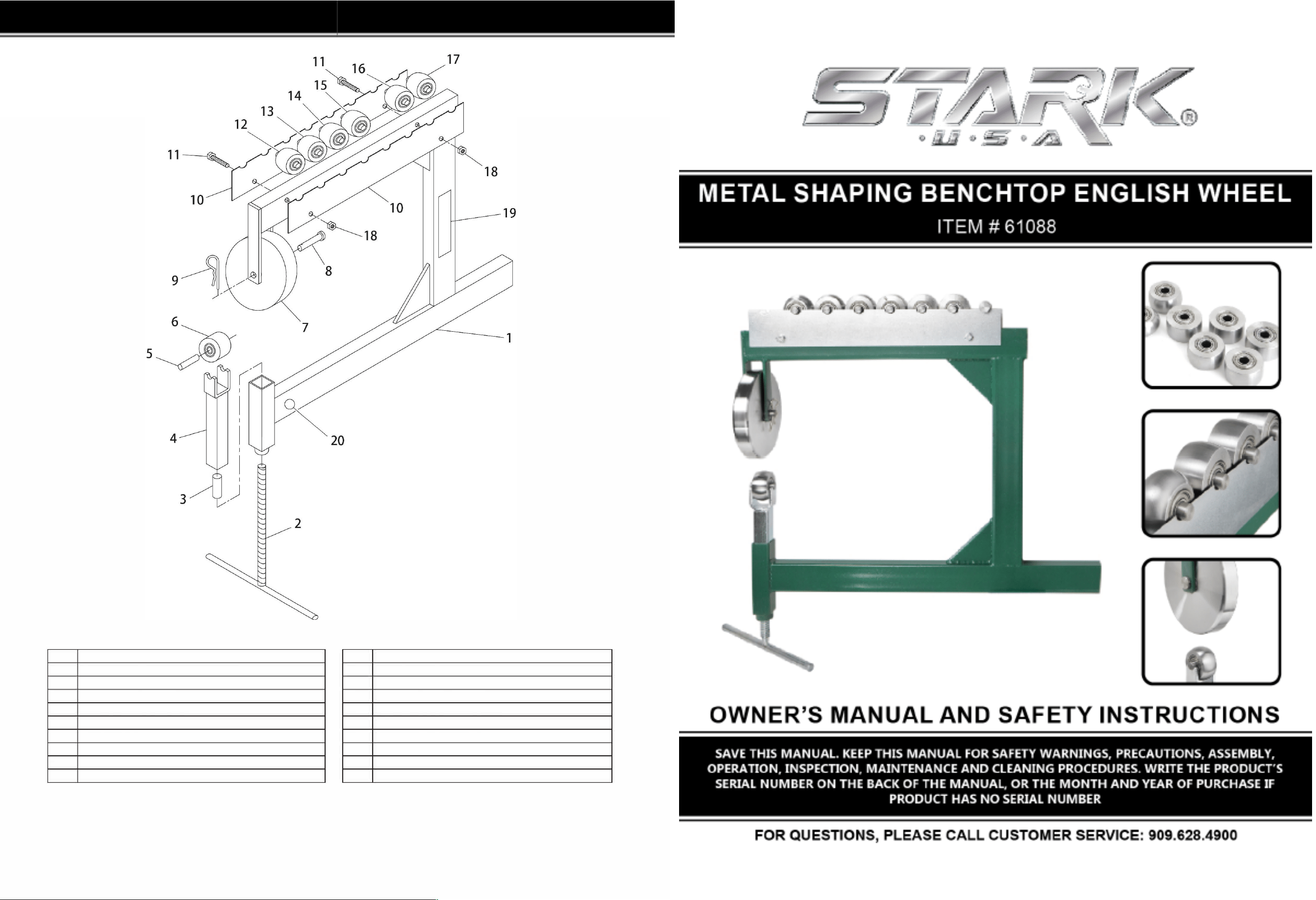
REF DESCRIPTION REF DESCRIPTION
1 FRAME 11 HEX BOLT 1/4-20 X 1-1/4
2 LOWER WHEEL ADJUSTMENT SCREW 12 LOWER WHEEL 1/2" RADIUS
3 BRACKET SPACER ROD 13 LOWER WHEEL 1" RADIUS
4 LOWER WHEEL BRACKET 14 LOWER WHEEL 1-1/2" RADIUS
5 LOWER WHEEL AXLE ROD 15 LOWER WHEEL 2-1/2" RADIUS
6 FLAT LOWER WHEEL 16 LOWER WHEEL 5" RADIUS
7 UPPER WHEEL 17 LOWER WHEEL 9" RADIUS
8 UPPER WHEEL CAPTIVE PIN 18 HEX NUT 1/4-20
9 HAIRPIN COTTER PIN 3/8 X 1-7 /8 19 MACHINE ID LABEL
10 WHEEL STORAGE RACK 20 GRIZZLY GREEN TOUCH-UP PAINT
-18-
PARTS INFORMATION
