
Operating Instructions and Parts Manual
45-inch English Wheel
Model: WH-45T
WALTER MEIER (Manufacturing), Inc.
427 New Sanford Road
LaVergne, Tennessee 30786 Part No. M-756151
Ph.: 800-274-6848 Revision A 06/2011
www.waltermeier.com Copyright © 2011 Walter Meier (Manufacturing), Inc.
2
Warranty and Service
Walter Meier (Manufacturing) Inc., warrants every product it sells. If one of our tools needs service or repair, one of
our Authorized Service Centers located throughout the United States can give you quick service. In most cases, any
of these Walter Meier Authorized Service Centers can authorize warranty repair, assist you in obtaining parts, or
perform routine maintenance and major repair on your JET
®
tools. For the name of an Authorized Service Center in
your area call 1-800-274-6848.
MORE INFORMATION
Walter Meier is consistently adding new products to the line. For complete, up-to-date product information, check with
your local Walter Meier distributor, or visit waltermeier.com.
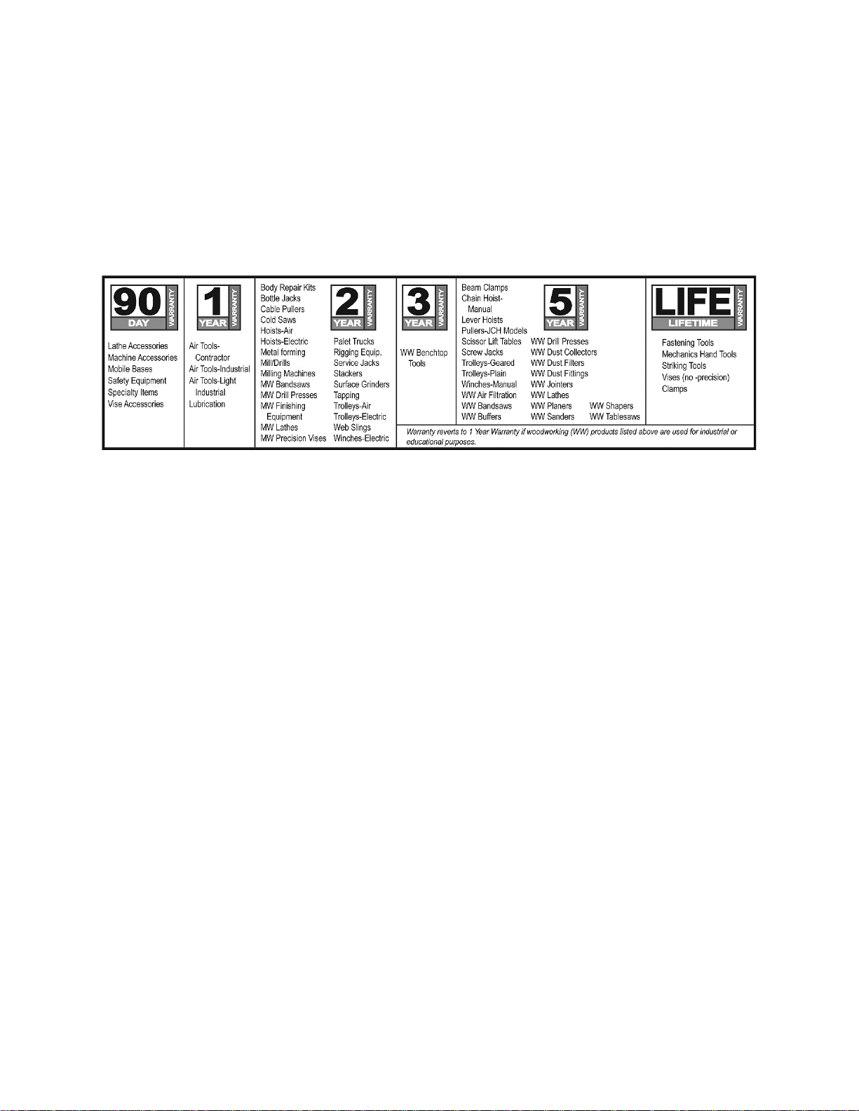
WARRANTY
JET products carry a limited warranty which varies in duration based upon the product (MW = Metalworking, WW =
Woodworking).
WHAT IS COVERED?
This warranty covers any defects in workmanship or materials subject to the exceptions stated below. Cutting tools,
abrasives and other consumables are excluded from warranty coverage.
WHO IS COVERED?
This warranty covers only the initial purchaser of the product.
WHAT IS THE PERIOD OF COVERAGE?
The general JET warranty lasts for the time period specified in the product literature of each product.
WHAT IS NOT COVERED?
Five Year Warranties do not cover woodworking (WW) products used for commercial, industrial or educational
purposes. Woodworking products with Five Year Warranties that are used for commercial, industrial or education
purposes revert to a One Year Warranty. This warranty does not cover defects due directly or indirectly to misuse,
abuse, negligence or accidents, normal wear-and-tear, improper repair or alterations, or lack of maintenance.
HOW TO GET SERVICE
The product or part must be returned for examination, postage prepaid, to a location designated by us. For the name
of the location nearest you, please call 1-800-274-6848.
You must provide proof of initial purchase date and an explanation of the complaint must accompany the
merchandise. If our inspection discloses a defect, we will repair or replace the product, or refund the purchase price,
at our option. We will return the repaired product or replacement at our expense unless it is determined by us that
there is no defect, or that the defect resulted from causes not within the scope of our warranty in which case we will,
at your direction, dispose of or return the product. In the event you choose to have the product returned, you will be
responsible for the shipping and handling costs of the return.
HOW STATE LAW APPLIES
This warranty gives you specific legal rights; you may also have other rights which vary from state to state.
LIMITATIONS ON THIS WARRANTY
WALTER MEIER (MANUFACTURING) INC., LIMITS ALL IMPLIED WARRANTIES TO THE PERIOD OF THE
LIMITED WARRANTY FOR EACH PRODUCT. EXCEPT AS STATED HEREIN, ANY IMPLIED WARRANTIES OR
MERCHANTABILITY AND FITNESS ARE EXCLUDED. SOME STATES DO NOT ALLOW LIMITATIONS ON HOW
LONG THE IMPLIED WARRANTY LASTS, SO THE ABOVE LIMITATION MAY NOT APPLY TO YOU.
WALTER MEIER SHALL IN NO EVENT BE LIABLE FOR DEATH, INJURIES TO PERSONS OR PROPERTY, OR
FOR INCIDENTAL, CONTINGENT, SPECIAL, OR CONSEQUENTIAL DAMAGES ARISING FROM THE USE OF
OUR PRODUCTS. SOME STATES DO NOT ALLOW THE EXCLUSION OR LIMITATION OF INCIDENTAL OR
CONSEQUENTIAL DAMAGES, SO THE ABOVE LIMITATION OR EXCLUSION MAY NOT APPLY TO YOU.
Walter Meier sells through distributors only. The specifications in Walter Meier catalogs are given as general
information and are not binding. Members of Walter Meier reserve the right to effect at any time, without prior notice,
those alterations to parts, fittings, and accessory equipment which they may deem necessary for any reason
whatsoever. JET
®
branded products are not sold in Canada by Walter Meier.

3
Table of Contents
Warranty and Service..........................................................................................................................2
Table of Contents ...............................................................................................................................3
Warnings............................................................................................................................................4
Introduction ........................................................................................................................................6
Specifications .....................................................................................................................................6
Unpacking and Setup ..........................................................................................................................7
Clea nup ..........................................................................................................................................7
Site Considerations .........................................................................................................................7
Moving the English Wheel ................................................................................................................7
Securing to Floor .............................................................................................................................7
Operation ...........................................................................................................................................7
Overview ........................................................................................................................................7
Basic Operations .............................................................................................................................8
Adjustments .......................................................................................................................................8
Replacing the Wheel .......................................................................................................................8
Rotating Wheels ..............................................................................................................................9
Rolling Tips ................................................................................................................................... 10
Adjusting the Quick Release Lever ................................................................................................. 10
Wheel Alignment ........................................................................................................................... 10
Lubrication ....................................................................................................................................... 11
Troubleshooting the WH-45T English Wheel....................................................................................... 12
Parts ................................................................................................................................................ 12
Ordering Replacement Parts .......................................................................................................... 12
Assembly Drawing for WH-45T English Wheel ................................................................................ 13
Parts List for WH-45T English Wheel .............................................................................................. 14
Wheel Chart .................................................................................................................................. 16
The specifications in this manual are given as general information and are not binding. Walter Meier
(Manufacturing) Inc., reserves the right to effect, at any time and without prior notice, changes or
alterations to parts, fittings, and accessory equipment deemed necessary for any reason whatsoever.

4
Warnings
1. Read and understand the entire owner’s manual before attempting assembly or operation.
2. Read and understand the warnings posted on the machine and in this manual. Failure to comply with
all of these warnings may cause serious injury.
3. Replace warning labels if they become obscured or removed.
4. This English wheel is designed and intended for use by properly trained and experienced personnel
only. If you are not familiar with the proper and safe operation of an English wheel, do not use until
proper training and knowledge have been obtained.
5. Do not use this English wheel for other than its intended use. If used for other purposes, Walter Meier
(Manufacturing) Inc., disclaims any real or implied warranty and holds itself harmless from any injury
that may result from that use.
6. Always wear approved safety glasses/face shields while using this English wheel. Everyday
eyeglasses only have impact resistant lenses; they are not safety glasses.
7. Before operating this English wheel, remove tie, rings, watches and other jewelry, and roll sleeves up
past the elbows. Remove all loose clothing and confine long hair. Non-slip footwear or anti-skid floor
strips are recommended.
8. Some dust created by power sanding, sawing, grinding, drilling and other construction activities
contain chemicals known to cause cancer, birth defects or other reproductive harm. Some examples
of these chemicals are:
• Lead from lead based paint.
• Crystalline silica from bricks, cement and other masonry products.
• Arsenic and chromium from chemically treated lumber.
Your risk of exposure varies, depending on how often you do this type of work. To reduce your
exposure to these chemicals, work in a well-ventilated area and work with approved safety
equipment, such as face or dust masks that are specifically designed to filter out microscopic
particles.
9. Do not operate this machine while tired or under the influence of drugs, alcohol or any medication.
10. Remove adjusting keys and wrenches. Form a habit of checking to see that keys and adjusting
wrenches are removed from the machine before using.
11. Keep safety guards in place at all times when the machine is in use. If removed for maintenance
purposes, use extreme caution and replace the guards immediately.
12. If possible, the English Wheel should be secured to the floor before use.
13. Check damaged parts. Before further use of the machine, a guard or other part that is damaged
should be carefully checked to determine that it will operate properly and perform its intended
function. Check for alignment of moving parts, binding of moving parts, breakage of parts, mounting
and any other conditions that may affect its operation. A guard or other part that is damaged should
be properly repaired or replaced.
14. Provide for adequate space surrounding work area and non-glare, overhead lighting.
15. Keep the floor around the machine clean and free of scrap material, oil and grease.
16. Keep visitors a safe distance from the work area. Keep children away.
17. Make your workshop child proof with padlocks, master switches or by removing starter keys.
18. Give your work undivided attention. Looking around, carrying on a conversation and “horse-play” are
careless acts that can result in serious injury.
19. Do not overreach. Keep proper footing and balance at all times.

5
20. Use the right tool at the correct feed rate. Do not force a tool or attachment to do a job for which it
was not designed. The right tool will do the job better and more safely.
21. Use recommended accessories; improper accessories may be hazardous.
22. Maintain tools with care. Keep wheels clean for best performance. Follow instructions for lubricating
and changing accessories.
23. Use leather gloves when handling steel work pieces.
24. Do not stand on the machine. Serious injury could occur if the machine tips over.
25. Remove loose items and unnecessary work pieces from the area before using the machine.
Familiarize yourself with the following safety notices used in this manual:
This means that if precautions are not heeded, it may result in minor injury and/or
possible machine damage.
This means that if precautions are not heeded, it may result in serious injury or possibly
even death.

6
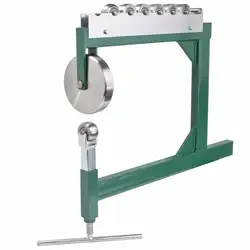
Introduction
This manual is provided by Walter Meier (Manufacturing) Inc., covering the safe operation and
maintenance procedures for the JET WH-45T English Wheel. This manual contains instructions on
installation, safety precautions, general operating procedures, maintenance instructions and parts
breakdown. This machine has been designed and constructed to provide years of trouble free operation if
used in accordance with instructions set forth in this manual. If there are any questions or comments,
please contact either your local supplier or Walter Meier. Walter Meier can also be reached at our web
site: www.waltermeier.com.
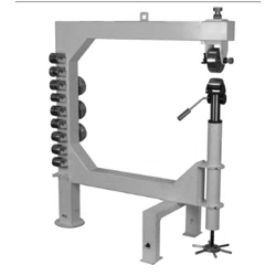
Specifications
Model...................................................................................................................................... WH-45T
Stock Number .......................................................................................................................... 756151
Number of lower wheels provided ...................................................................................................... 10
Number of upper wheels provided........................................................................................................ 4
Construction:
Frame .......................................................................... 4-3/4" square, 7-gauge gusseted steel tubing
Wheels ......................................................................................................................hardened steel
Number of lower wheel storage holders ......................................................................................... 10
Number of upper wheel storage holders .......................................................................................... 3
Capacities:
Mild Steel .............................................................................................................. 16 Gauge (0.06")
Aluminum .................................................................................................................................. 1/8"
Copper .................................................................................................................. 16 Gauge (0.05")
Dimensions:
Throat ........................................................................................................................................ 45"
Adjustment Post Diameter ..................................................................................................... 2-7/16"
Footprint ............................................................................................................................ 59" x 28"
Overall Dimensions, shipped...............................................................................67"L x 59" W x 15"H
Overall Dimensions, assembled ..........................................................................56"L x 28" W x 63"H
Weights:
Shipping .............................................................................................................................. 555 lbs.
Net ...................................................................................................................................... 458 lbs.
The above specifications were current at the time this manual was published, but because of our policy of
continuous improvement, Walter Meier reserves the right to change specifications at any time and without
prior notice, without incurring obligations.
Read and understand the entire contents of this manual before attempting
assembly or operation. Failure to comply may cause serious injury.
7
Unpacking and Setup
Cleanup
Exposed metal surfaces, including upper and
lower wheels, are coated with a protectant to
resist corrosion during shipment. Remove this
coating with a soft rag and a solvent or cleaner-
degreaser. Some parts may need to be removed
for thorough cleaning. Do not use gasoline,
acetone, lacquer thinner or other highly volatile
solvents, as these will damage painted surfaces.
Site Considerations
Floor Stability – Refer to the weight and footprint
specifications for the machine. Residential floors
may require additional reinforcement to support
both machine and operator.
Operating Clearances – When establishing a
location for your machine, consider existing and
anticipated needs, size of workpiece to be
processed, space for auxiliary stands, work
tables or other machinery that may be present.
To prevent personal injury,
do not allow unsupervised children or
visitors in your shop at any time!
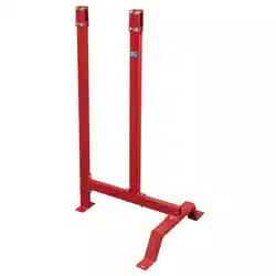
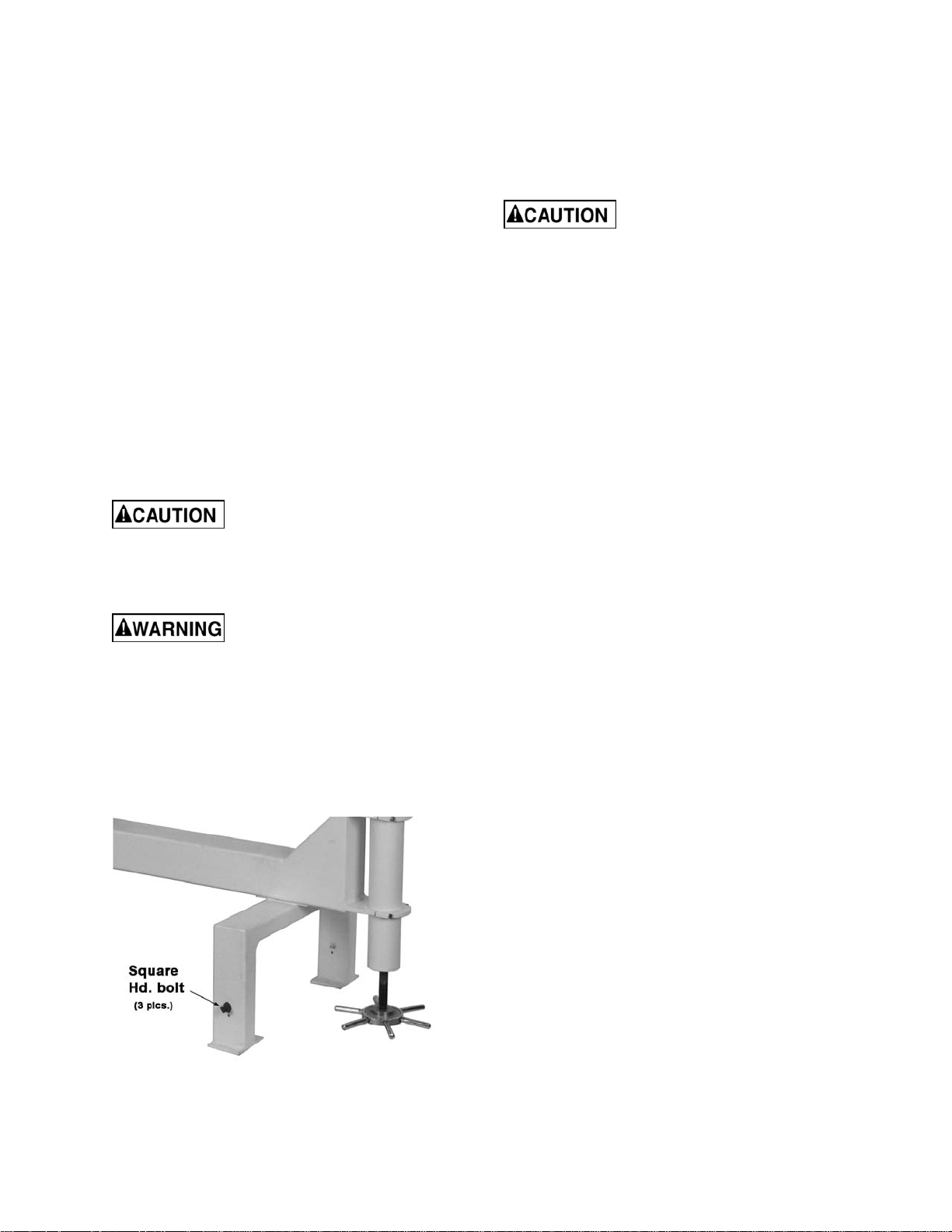
Moving the English Wheel
The WH-45T is a heavy
machine. Get assistance when unpacking.
Retractable wheels beneath the main column
and support legs allow the machine to be moved
by one person. Rotate the three square head
bolts (Figure 1) with a wrench to lower or raise
the wheels.
NOTE: Always retract the wheels before
operating the machine.
Figure 1
Securing to Floor
Mounting the machine to the floor is strongly
recommended (floor mounting hardware is not
included). Lag shield anchors with lag bolts and
anchor studs are recommended for anchoring to
a concrete floor. Research mounting methods
and choose one that best fits your application.
Secure machine to the floor
to prevent instability and possible tipping
during operation.
Operation
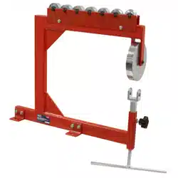
Overview
As the metal workpiece is rolled between the
upper wheel and lower wheel, it becomes longer
and thinner. At the same time, a track is pressed
into the metal, creating a convex curve in the
workpiece.
A variety of contours can be produced by
varying the amount and pattern of the tracks.
The English wheel can produce curves in mild
steel up to 16 gauge (0.06"), copper up to 16
gauge (0.05") and aluminum up to 1/8".
8
Basic Operations
1. Clean the workpiece and wheels thoroughly,
removing any grit or abrasive particles.
NOTE: Grit or dirt can mar the workpiece
and even damage the wheels.
De-burr sharp metal edges and wear leather
gloves while handling sheet metal, to
prevent injury to your hands.
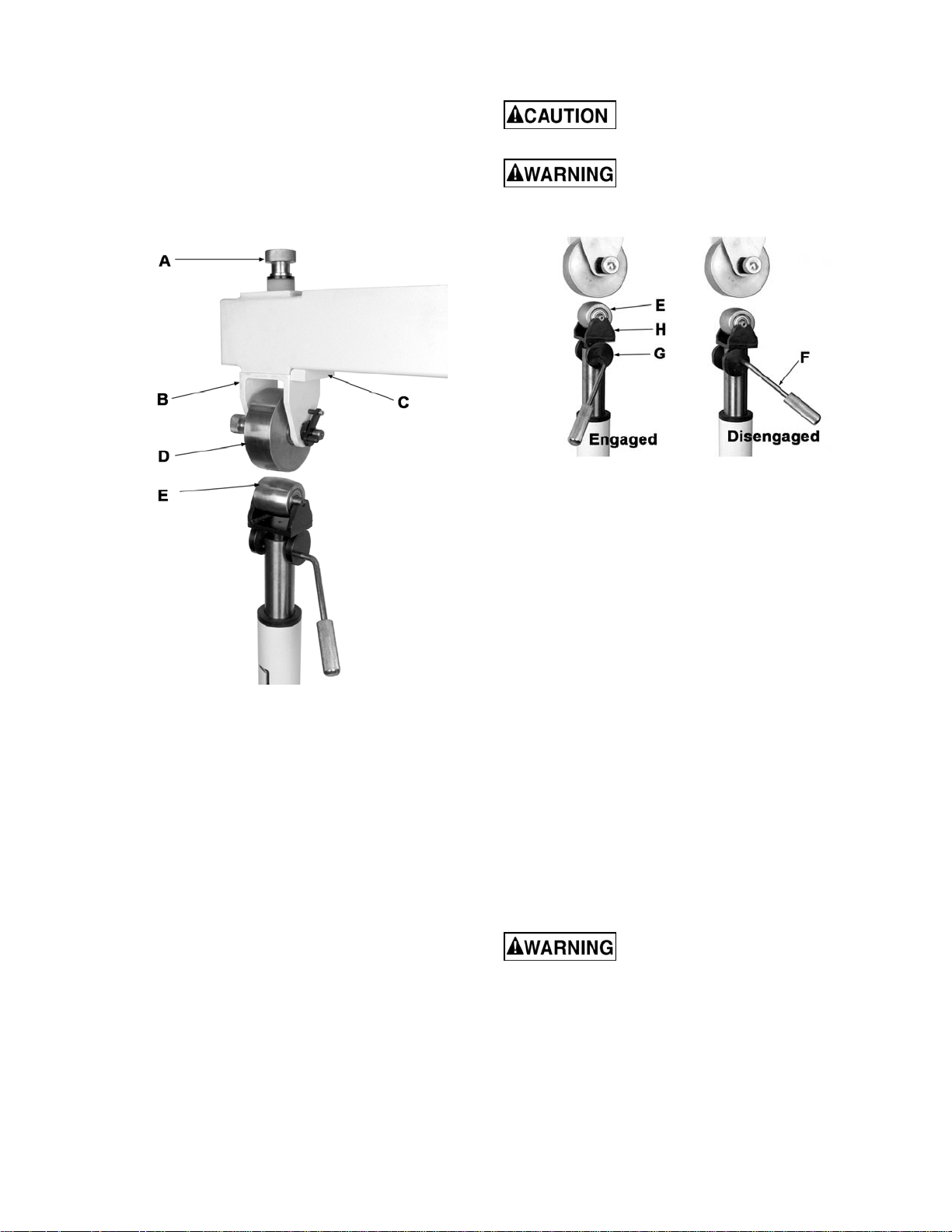
Figure 2
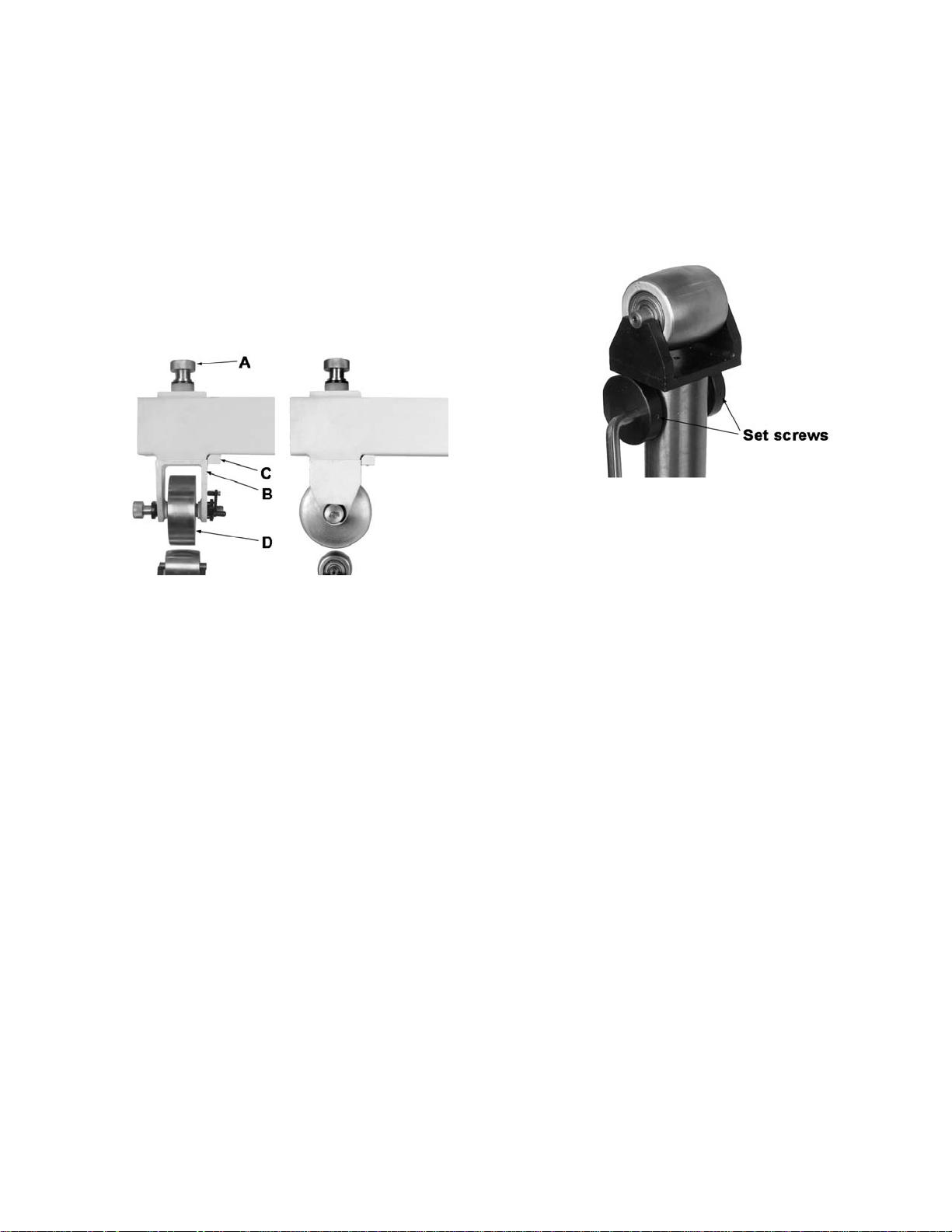
Refer to Figure 2:
2. Turn the upper wheel knob (A) clockwise to
raise the upper wheel bracket (B) against
the frame as shown.
Note: Make sure the upper wheel bracket
(B) and frame block (C) edges are parallel
so that they slide past each other when
raising the upper wheel bracket. Otherwise,
they may bind.
3. Check the distance between bottom of the
upper wheel (D) and top of the lower wheel
(E). They should be about an inch apart. To
adjust the distance, rotate the adjusting
wheel (shown in Figure 10) to raise or lower
the lower wheel (E).
Refer to Figure 3:
4. Place the quick release lever (F) in the
engaged position to raise the lower wheel
(E) to the operating position. Engaged
position is where the flat edge on the cam
(G) rests against the bottom of the lower
wheel bracket (H).
Pinch Hazard! Do not place
fingers in wheel path during operation.
Sharp metal edges can cause
lacerations. De-burr sharp edges and wear
leather gloves when handling.
Figure 3
5. Insert the workpiece between the wheels.
6. Rotate the adjusting wheel (shown in Figure
10) counter-clockwise until there is light
pressure on the workpiece.
7. Roll the workpiece up to an edge, rotate it
slightly then pull it back.
8. Turn the adjusting wheel counterclockwise
to increase pressure on the workpiece; turn
the adjusting wheel clockwise to decrease
pressure.
Note: To reinsert a workpiece or insert
another workpiece of the same thickness,
use the quick release lever (F, Figure 3).
Adjustments
Replacing the Wheel
The JET English Wheel is provided with 4 upper
wheels and 10 lower wheels. Their profiles are
shown at the back of this manual.
Hold upper wheel securely
when installing or removing. Wear steel-toed
footwear for personal safety.
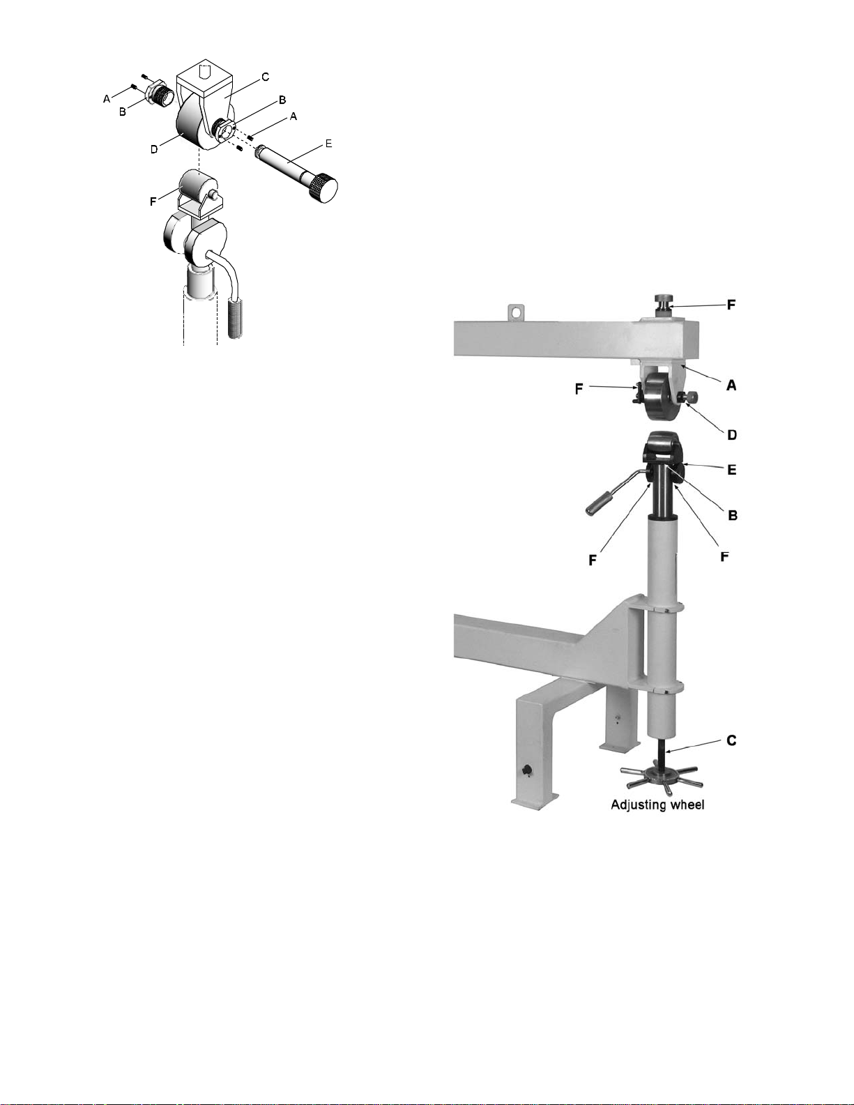
To replace an upper wheel:
Refer to Figure 4.
1. Raise the lower wheel (E) until it contacts
the bottom of the upper wheel (D). This
ensures the upper wheel is supported.
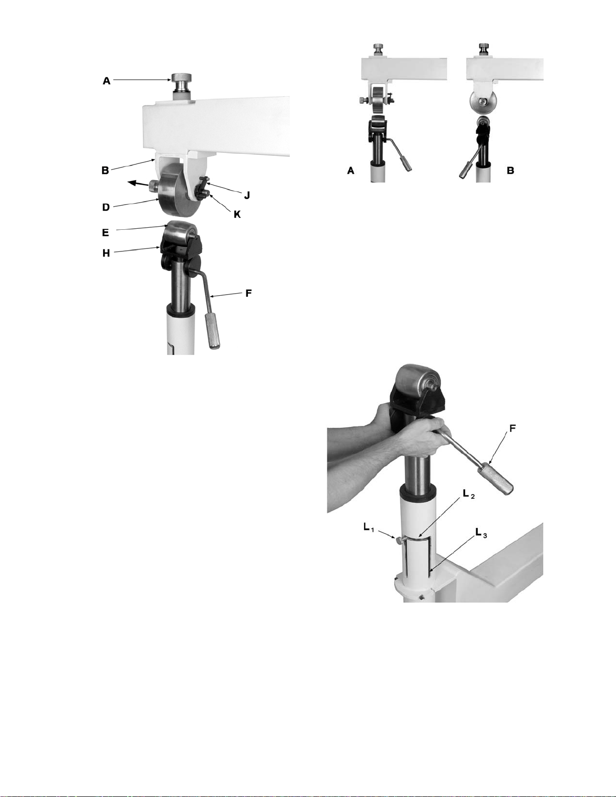
9
2. Flip up the latch (J) and slide out the upper
wheel axle (K) while holding the wheel.
Figure 4
3. Carefully remove the upper wheel (D) and
set it on a bracket on the upper wheel rack.
4. Place a new upper wheel into position. Align
the wheel bearing holes with the bracket
mounting holes, insert the axle (K), and
rotate the latch (J) to secure the wheel.
Note: Adjust the lower wheel height if you
need more clearance replacing the upper
wheel.
To replace a lower wheel:
1. Disengage the quick release lever (F, Figure
4) and lower the lower wheel bracket (H,
Figure 4) until there’s sufficient clearance.
2. Remove the lower wheel (E, Figure 4) and
replace it with another one.
3. Engage the quick release lever (F, Fig. 2)
and raise the lower wheel to the operating
position.
Rotating Wheels
The wheels can be positioned perpendicular to
the frame (A, Figure 5) for long workpieces or
parallel to the frame (B, Figure 5) for wide
workpieces.
Figure 5
To rotate lower wheel:
Refer to Figure 6.
1. Disengage quick release lever (F).
2. Remove lower wheel if needed for
clearance.
3. Lift the lower wheel assembly until the
knurled screw (L) reaches the top of the
groove in which it is currently positioned
(L
1
).
Figure 6
4. Rotate the lower wheel assembly, sliding the
knurled screw (L) along the entire distance
of the horizontal groove (L
2
).
5. Lower the lower wheel assembly until it reaches
the bottom of the opposite groove (L
3
).
10
To rotate upper wheel:
Refer to Figure 7.
6. Remove the lower wheel to provide clear-
ance for the following steps.
7. Turn the upper wheel knob (A) counter-
clockwise to lower the upper wheel bracket
(B) below the frame block (C).
8. Rotate the upper wheel 90 degrees (D), then
raise the upper wheel bracket (B) until it is
seated against the frame.
9. Reinstall lower wheel, engage the quick
release lever, and raise lower wheel to the
operating position.
Figure 7
Rolling Tips
Observe the following tips for successful
operation of the English Wheel:
• Make sure workpiece and wheels are clean
and free of any debris.
• Start rolling slowly, then increase speed.
• Try rolling the wheels up to, but not past the
workpiece edge.
• Mark the workpiece with a non-permanent
marker to contour the metal or follow
tracking patterns.
• Use the lightest wheel pressure possible to
shape the workpiece. Too much pressure
will crease or ruin the metal.
• Use light pressure for smoothing, high
pressure for rough shaping.
Adjusting the Quick Release Lever
Refer to Figure 8:
The quick release lever is adjusted at the
factory. However, it may have become loose
during shipping. The set screws must engage
the lever to prevent it from slipping.
To adjust the quick release lever:
1. Examine the flats on the quick release lever.
Figure 8
If a setscrew does not contact a flat on the lever:
2. Use a hex wrench to loosen the setscrews.
Turn the quick release lever so that the
setscrew is aligned with the flat on the lever,
then tighten the setscrews.
Wheel Alignment
Wheel alignment can be adjusted by positioning
the upper wheel with respect to the lower wheel.
Refer to Figure 9:
1. Loosen four setscrews (A).
2. Determine the direction that the upper wheel
should be shifted to align with the lower
wheel.
3. Turn the corresponding adjusting nut (B)
outward (counterclockwise) in small
incremental steps and the other adjusting
nut inward by the same amount.
4. Tighten the four setscrews(A).
11
Figure 9
Lubrication
Refer to Figure 10:
The following areas should be kept lubricated:
Upper wheel bracket (A)
Lower wheel bracket (B)
Jack screw (C)
Upper wheel axle (D)
Cams (E)
Pivot points (F)
Upper and Lower Wheel Brackets
Periodically lower the upper wheel bracket, and
apply a light coating of lithium grease to the post
(A).
Apply a light coating of oil, such as SAE 30W, to
the lower wheel bracket (B).
Jack Screw
Apply lithium grease as needed to the screw
threads (C).
Cams
Apply a coating of lithium grease to the cams (E)
where they contact the bottom of the lower
wheel bracket.
Pivot Points
Apply a small amount of oil, such as SAE 30W,
to the pivot points (F).
Wheels
When upper or lower wheels are not being used,
or are stored away, apply a light coat of oil to
prevent rust. Wipe off the oil before using the
wheels.
Figure 10

12
Troubleshooting the WH-45T English Wheel
Trouble Probable Cause Remedy
Quick release lever
will not engage, or
engages with
difficulty.
Lower wheel bracket and cams are
binding.
Setscrews on cams loose, not
contacting quick release lever flats.
Lubricate contact points between top of
cams and bracket.
Align setscrews with lever flats and
tighten.
Upper wheel
swivels.
Upper wheel not secured to frame
bracket.
Turn upper wheel knob clockwise until
upper wheel bracket is snug against
frame bracket.
Wheel does not
shape workpiece.
Workpiece too thick.
Crown is too low.
Incorrect pressure.
Use sheet metal of appropriate
thickness.
Use a lower wheel with a higher crown.
Increase pressure on workpiece.
Upper wheel
bracket will not seat
against frame.
Upper wheel bracket catches on
frame block; surfaces are not parallel.
Align upper wheel and upper frame
block surfaces when raising upper
wheel bracket to frame.
Wheels form too
high a crown in
workpiece.
Lower wheel flat is too small. Use a lower wheel with a larger flat.
Wheels form too
low a crown
Lower wheel flat is too large. Use a lower wheel with a smaller flat.
Parts
Ordering Replacement Parts
To order parts or reach our service department, call 1-800-274-6848 Monday through Friday (see our
website for business hours, www.waltermeier.com). Having the Model Number and Serial Number of your
machine available when you call will allow us to serve you quickly and accurately.
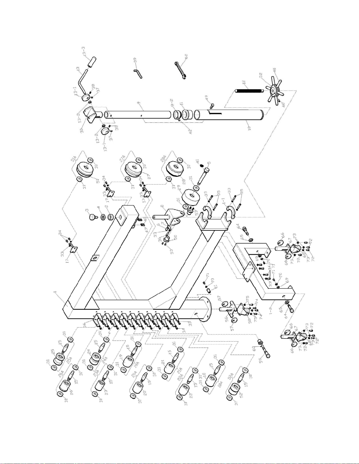
13
Assembly Drawing for WH-45T English Wheel

14
Parts List for WH-45T English Wheel
Index No. Part No. Description Size Qty
1 .............. WH45T-1 ................Frame ................................................................................................ 1
1-1 ........... WH45T-1-1..............Post Clamp ........................................................................................ 2
1-2 ........... WH45T-1-2..............Frame Support Stand .......................................................................... 1
2 .............. WH45-2...................Collar ................................................................................................. 1
3 .............. WH45-3...................Adjusting Lock Knob ........................................................................... 1
4 .............. WH45-4...................Washer .............................................................................................. 1
5 .............. WH45-5...................Upper Wheel Shaft ............................................................................. 1
6 .............. WH45-6...................Short Pin ............................................................................................ 1
7 .............. WH45-7...................Position Block..................................................................................... 1
8 .............. WH45-8...................Upper Wheel Housing ......................................................................... 1
9 .............. WH45-9...................Inner Tube Adjusting Post ................................................................... 1
9-2 ........... WH45-9-2................Collar ................................................................................................. 1
10 ............ WH45-10 .................Outer Post.......................................................................................... 1
11 ............ WH45-11 .................Flange Bushing .................................................................................. 1
12 ............ WH45-12 .................Lead Screw ........................................................................................ 1
13 ............ WH45-13 .................Lifting Lever ....................................................................................... 1
13-1 ......... WH45-13-1 ..............Cam................................................................................................... 2
13-2 ......... WH45-13-2 ..............Spacer ............................................................................................... 2
13-3 ......... WH45-13-3 ..............Lifting Lever Handle ............................................................................ 1
15 ............ WH45-15 .................Lower Wheel Shaft ........................................................................... 10
16 ............ WH45-16 .................Lower Wheel Storage Bracket ........................................................... 10
17 ............ WH45-17 .................Upper Wheel Storage Bracket ............................................................. 3
18A.......... WH45-18A ..............Lower Wheel 1 Assembly (Index #18, 15, 31) .....1/8” Edge ................... 1
18 ............ WH45-18 .................Lower Wheel 1 ................................................................................... 1
19A.......... WH45-19A ..............Lower Wheel 9 Assembly (Index #19, 15, 31) .....1/2" Ridged ................ 1
19 ............ WH45-19 .................Lower Wheel 9 ................................................................................... 1
20A.......... WH45-20A ..............Lower Wheel 7 Assembly (Index #20, 15, 31) .....1/8" Ridged ................ 1
20 ............ WH45-20 .................Lower Wheel 7 ................................................................................... 1
21A.......... WH45-21A ..............Lower Wheel 6 Assembly (Index #21, 15, 31) .....1/4" ............................ 1
21 ............ WH45-21 .................Lower Wheel 6 ................................................................................... 1
22A.......... WH45-22A ..............Lower Wheel 8 Assembly (Index #22, 15, 31) .....3/4" ............................ 1
22 ............ WH45-22 .................Lower Wheel 8 ................................................................................... 1
23A.......... WH45-23A ..............Lower Wheel 4 Assembly (Index #23, 15, 31) .....2-1/4” ......................... 1
23 ............ WH45-23 .................Lower Wheel 4 ................................................................................... 1
24A.......... WH45-24A ..............Lower Wheel 3 Assembly (Index #24, 15, 31) .....3/4" ............................ 1
24 ............ WH45-24 .................Lower Wheel 3 ................................................................................... 1
25A.......... WH45-25A ..............Lower Wheel 2 Assembly (Index #25, 15, 31) .....1-29/64” ..................... 1
25 ............ WH45-25 .................Lower Wheel 2 ................................................................................... 1
26A.......... WH45-26A ..............Lower Wheel 5 Assembly (Index #26, 15, 31) .....2-5/8" ......................... 1
26 ............ WH45-26 .................Lower Wheel 5 ................................................................................... 1
27A.......... WH45-27A ..............Upper Wheel 10 Assembly (Index #27, 31) .........3/4" ............................ 1
27 ............ WH45-27 .................Upper Wheel 10 ................................................................................. 1
28A.......... WH45-28A ..............Upper Wheel 11 Assembly (Index #28, 31) .........1-29/64” ..................... 1
28 ............ WH45-28 .................Upper Wheel 11 ................................................................................. 1
29A.......... WH45-29A ..............Upper Wheel 12 Assembly (Index #29, 31) .........1/8” Edge ................... 1
29 ............ WH45-29 .................Upper Wheel 12 ................................................................................. 1
30 ............ WH45-30 .................Lower Wheel Housing ......................................................................... 1
31 ............ BB-6204ZZ ..............Ball Bearing......................................................6204ZZ .................... 28
32 ............ WH45-32 .................Adjusting Wheel ................................................................................. 1
33 ............ TS-1551041 ............Lock Washer ....................................................M6 ........................... 35
34 ............ TS-1503061 ............Socket Head Cap Screw ...................................M6x25...................... 30
35 ............ TS-1503111 ............Socket Head Cap Screw ...................................M6x50........................ 4
36 ............ TS-1503091 ............Socket Head Cap Screw ...................................M6x40........................ 1
37 ............ TS-1522031 ............Socket Set Screw .............................................M5x10........................ 2
38 ............ TS-1522041 ............Socket Set Screw .............................................M5x12........................ 2
39 ............ TS-152706 ..............Hex Wrench .....................................................5mm .......................... 1
40 ............ WH45-40 .................Wheel Handle..................................................................................... 6

15
Parts List for WH-45T English Wheel
Index No. Part No. Description Size Qty
41 ............ WH45-41 .................Snap Ring ........................................................Ø20 ........................... 1
42 ............ TS-1522031 ............Socket Set Screw .............................................M5x10........................ 1
46 ............ TS-1523021 ............Socket Set Screw .............................................M6x8 ......................... 1
47 ............ TS-1503071 ............Socket Head Cap Screw ...................................M6x30........................ 2
48 ............ WH45-48 .................Spring Pin ........................................................Ø5x30 ........................ 2
49 ............ WH45-49 .................Adjusting Lock Bolt ............................................................................. 1
50 ............ WH45-50 .................Adjusting Nut ...................................................................................... 2
51A.......... WH45-51A ..............Upper Wheel 13 Assembly (Index #51, 31) .........1/4" ............................ 1
51 ............ WH45-51 .................Upper Wheel 13 ................................................................................. 1
52A.......... WH45-52A ..............Lower Wheel 14 Assembly (Index #52, 15, 31) ...1/4" ............................ 1
52 ............ WH45-52 .................Lower Wheel 14 ................................................................................. 1
53 ............ TS-1523061 ............Socket Set Screw .............................................M6x20........................ 4
56 ............ WH45T-56...............Rear Caster Post ................................................................................ 1
57 ............ WH45T-57...............Rear Eccentric Wheel ......................................................................... 2
58 ............ WH45T-58...............Rear Caster......................................................Ø70 mm ..................... 1
59 ............ WH45T-59...............Rear Eccentric Wheel Shaft................................................................. 1
60 ............ WH45T-60...............Rear Bushing Shaft ............................................................................. 1
61 ............ WH45T-61...............Bushing.............................................................................................. 1
62 ............ WH45T-62...............Open End Wrench ............................................18 mm ....................... 1
64 ............ WH45T-64...............Front Eccentric Wheel Shaft ................................................................ 2
65 ............ WH45T-65...............Front Bushing Shaft ............................................................................ 2
66 ............ WH45T-66...............Front Eccentric Wheel ......................................................................... 4
67 ............ WH45T-67...............Front Wheel Post ................................................................................ 2
68 ............ WH45T-68...............Front Wheel .....................................................Ø70 mm ..................... 2
69 ............ WH45T-69...............Shaft Bushing ..................................................................................... 2
70 ............ WH45T-70...............Snap Ring .......................................................................................... 3
71 ............ TS-1503041 ............Socket Head Cap Screw ...................................M6x15........................ 3
72 ............ TS-1482041 ............Hex Cap Screw ................................................M6x20........................ 8
73 ............ TS-1550041 ............Flat Washer......................................................M6 ............................. 8
74 ............ TS-1504051 ............Socket Head Cap Screw ...................................M8x25........................ 4
75 ............ TS-1550041 ............Flat Washer......................................................M6 ............................. 4
Note: Upper and Lower Wheels can only be purchased as an assembly.
Part numbers beginning with TS- are standard fasteners and can usually be found at local
hardware stores.
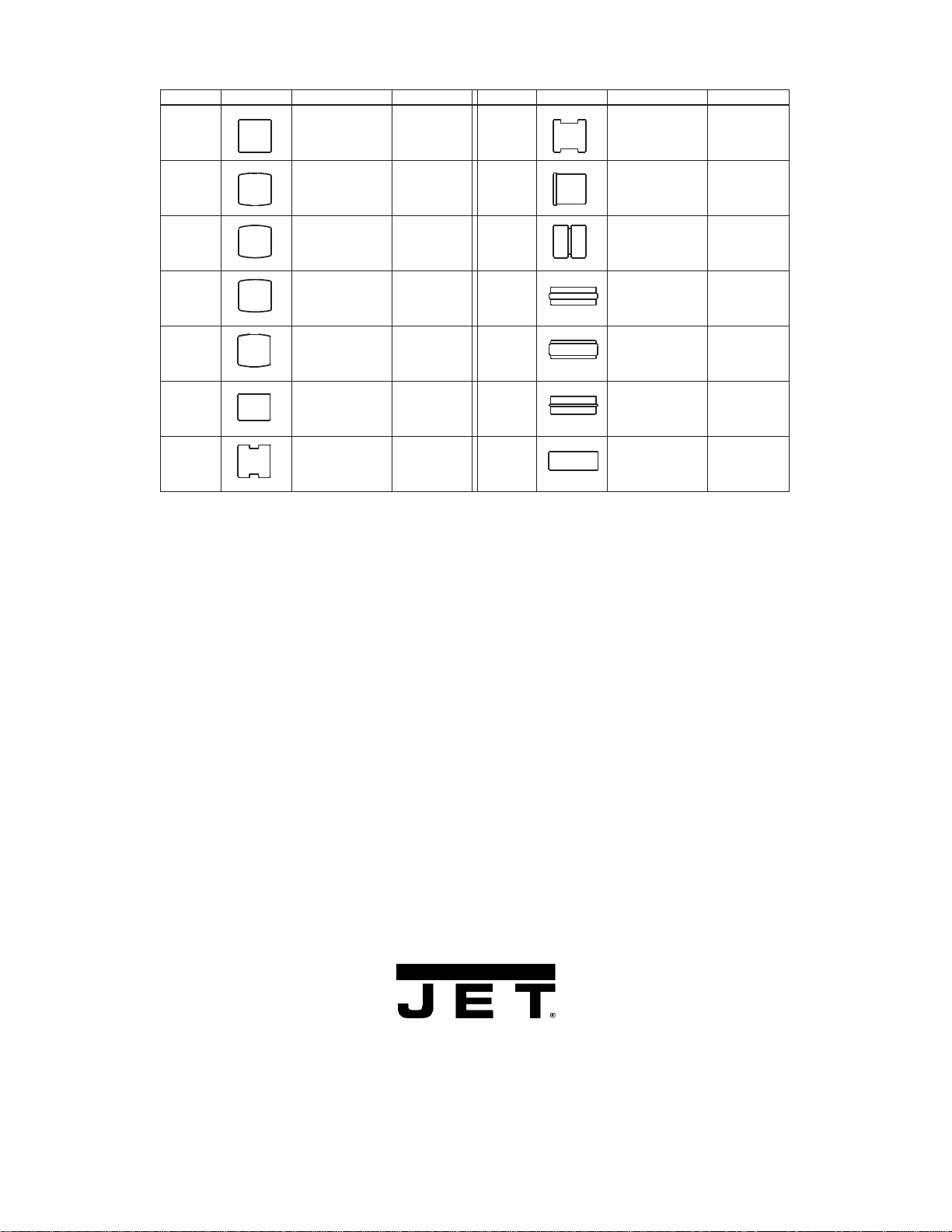
16
Wheel Chart
Lower wheel 1 1/8" Edge Lower wheel 2 1-29/64"
Lower wheel 9 1/2" Ridged Lower wheel 5 2-5/8"
Lower wheel 7 1/8" Ridged Lower wheel 14 1/4"
Lower wheel 6 1/4" Upper wheel 10 3/4"
Lower wheel 8 3/4" Upper wheel 11 1-29/64"
Lower wheel 4 2-1/4" Upper wheel 13 1/4"
Lower wheel 3 3/4" Upper wheel 12 1/8" Edge
Index No. Wheel Description Spec
18
19
20
21
22
23
24
25
26
52
27
28
51
29
Index No. Wheel Description Spec
To purchase a particular wheel, select the Index No. from the column to the left of the wheel and use that
number to determine the Part No. in the Parts List (preceding pages). Note that the wheel is sold as an
assembly only that includes the wheel, ball bearings and shaft (lower wheel only). For example, when ordering
Lower Wheel 1 (Index 18), order Part Number WH45-18A (Index 18A) from the Parts List on page 14.
WALTER MEIER (Manufacturing) Inc.
427 New Sanford Road
LaVergne, Tennessee 37086
Phone: 800-274-6848
www.waltermeier.com