01 02 03 04 05 06 07 08
09 10 11 12 13 14 15 16
17 18 19 20 21 22 23 24
25 26
SHENZHEN ANDOBIL TECHNOLOGY CO., LTD.
Address: RM C1407, BLK C, Zhantao Technology BLDG,
Intersection of Gongye East Road And Minzhi Road, Xinniu
Community, Minzhi ST, Longhua DIST, Shenzhen, China
Web: www.andobil.com
Email: [email protected]
Andobil is a trademark registered in the U.S. and other countries.
All rights reserved.
EN
JA
DE
Contents /目次/ Inhalt
Specifications ..................................................................................01
Overview...........................................................................................02
Installation ........................................................................................03
Instructions.......................................................................................05
Phone Case Compatibility...............................................................07
FAQ...................................................................................................08
Precautions ......................................................................................08
製品概要 ......................................................................................................... 10
各部の名称..................................................................................................... 11
取り付け方法................................................................................................. 12
使用方法 ......................................................................................................... 14
スマートフォンケースの互換性............................................................... 16
よくあるご質問.............................................................................................. 17
使用上のご注意............................................................................................ 17
Technische Daten............................................................................18
Übersicht..........................................................................................19
Montage ...........................................................................................20
Instructions.......................................................................................22
Kompatibilität mit Smartphone-Hüllen...........................................24
Häufig gestellte Fragen ...................................................................25
Sicherheitshinweise.........................................................................26
Made in China
xxxx
Two methods to get product installation videos:
1. Search our channel on YouTube
Andobil Official
2. Scan the QR code
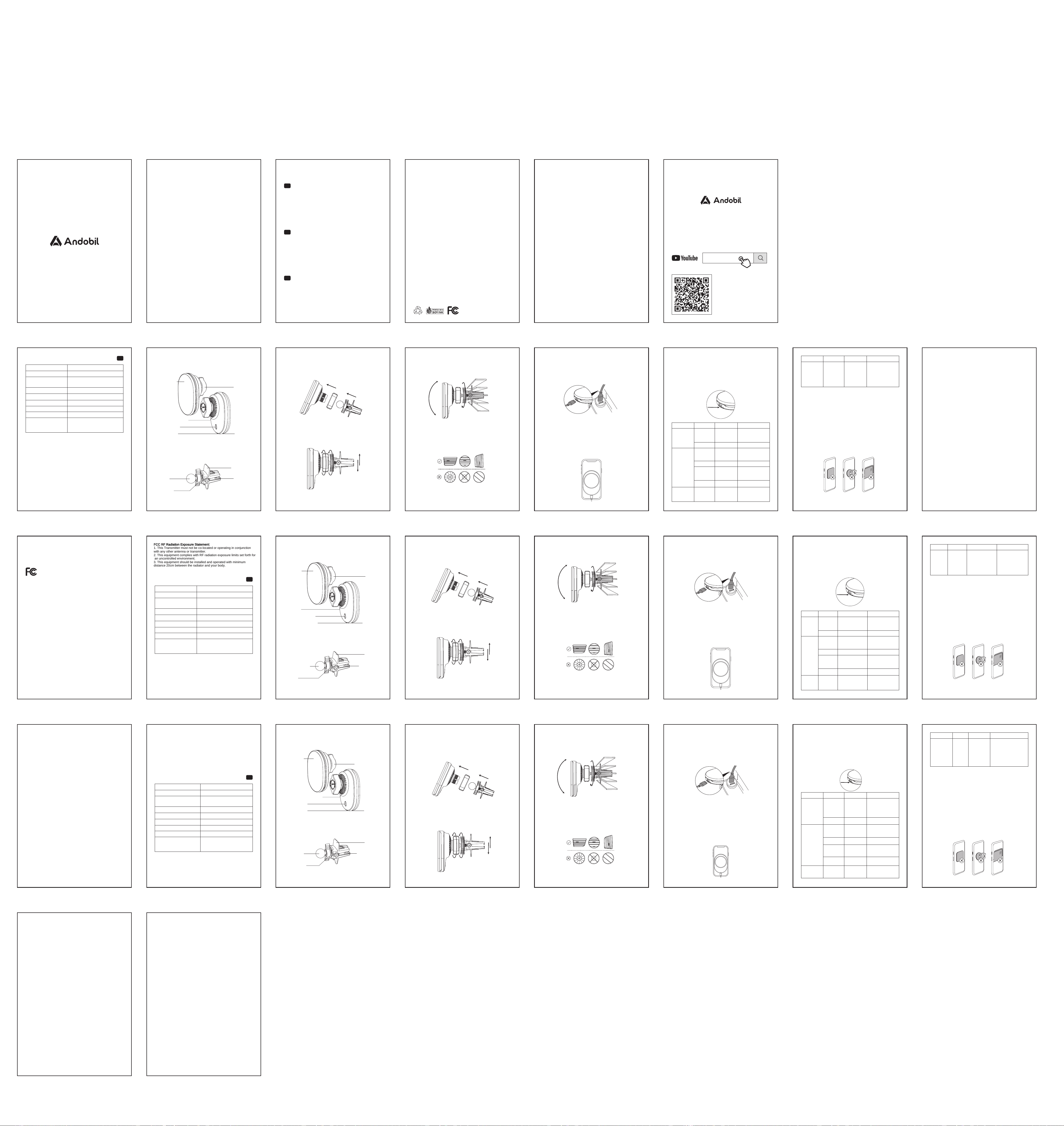
Specifications Overview Installation
Air Vent Compatibility
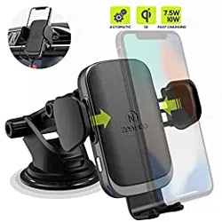
Magnetic Wireless Car Charger
Spiral Clamp
Übersicht
Magnetisches kabelloses Kfz-Ladegerät
Spiralklemme
Product Name Magnetic Wireless Charger
Model
Input
WZ1A
9.0V⎓3.0A/12.0V⎓3.0A/
15.0V⎓3.0A
Output
Charge Sensing Distance
25.0W Max
<4mm
The parameters above are derived from the laboratory of
ANDOBIL. The image shown here is indicative only. Actual
delivery is subject to customer purchase style.
Changes or modifications not expressly approved by the party
responsible for compliance could void the user's authority to
operate the equipment.
This equipment has been tested and found to comply with the
limits for a Class B digital device, pursuant to Part 15 of the FCC
Rules. These limits are designed to provide reasonable protection
against harmful interference in a residential installation. This
equipment generates, uses and can radiate radio frequency
energy and, if not installed and used in accordance with the
instructions, may cause harmful interference to radio
communications. However, there is no guarantee that interference
will not occur in a particular installation. If this equipment does
cause harmful interference to radio or television reception, which
can be determined by turning the equipment off and on, the user
is encouraged to try to correct the interference by one or more of
the following measures:
-- Reorient or relocate the receiving antenna.
-- Increase the separation between the equipment and receiver.
-- Connect the equipment into an outlet on a circuit different from
that to which the receiver is connected.
-- Consult the dealer or an experienced radio/TV technician for
help.
This device complies with Part 15 of the FCC Rules. Operation is
subject to the following two conditions: (1) this device may not
cause harmful interference, and (2) this device must accept any
interference received, including interference that may cause
undesired operation.
EN
Operating Temperature -10°C-40°C
Applicable Places air vent
Compatible Models iPhone 12 and newer
Wireless
Charging Area
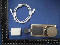
Package List
Magnetic Wireless Charger ×1,
Spiral Clamp×1, Charging Cable x1,
User Manual ×1
Technische Daten
Produktname
Modell
Eingang
Ausgang
Ladeerkennungsabstand
Die oben genannten Parameter stammen aus dem Labor von
ANDOBIL. Die Abbildungen dienen ausschließlich zur
Veranschaulichung; maßgeblich ist das tatsächlich gelieferte
Produkt. Der tatsächliche Lieferumfang richtet sich nach der vom
Kunden erworbenen Ausführung.
Betriebstemperatur
Geeignete Montageflächen
Kompatible Modelle
Lieferumfang
Magnetic Wireless Charger
WZ1A
9.0V⎓3.0A/12.0V⎓3.0A/
15.0V⎓3.0A
Max. 25.0W
<4mm
-10°C-40°C
Luftauslass
iPhone 12 und höher
Magnetic Wireless Charger ×1,
Spiralklemme ×1, Ladekabel ×1,
Bedienungsanleitung ×1
1. Unscrew the locking nut. Insert the ball joint through the
smaller opening of the locking nut, then firmly press the ball
joint into the socket on the back of the support arm.
Instructions
1. Connect to Power
Precautions
1. Ensure the product is properly installed to prevent it from
coming loose or falling.
2. Do not disassemble or modify the product to avoid damage.
3. Install the product before driving. Do not operate or adjust it
while driving.
Phone Case Compatibility
① Compatible with phone cases that have a smooth surface and
are 4 mm (0.16 in) thick or less.
② Not compatible with:
FAQ
1. If the device does not charge properly or charges slowly,
please check the following:
1.1 A solid green indicator light in standby mode indicates that
the device is ready to charge.
1.2 To enable 25W, 15W, 10W, or 7.5W fast wireless charging,
use a car charger that supports PD 2.0 or later and provides
sufficient power. Do not connect the device directly to the
vehicle's built-in USB port.
1.3 Remove any metal objects from the phone or phone case,
such as metal rings, metal plates, credit cards, or
PopSockets.
1.4 Wireless charging supports phone cases up to 4 mm (0.16
in) thick.
1.5 High temperatures may reduce charging speed. For the
best charging performance, it is recommended to close
high-power apps such as navigation when the phone
battery is low and lower the vehicle's cabin temperature if
possible.
1.6 To ensure safe charging and optimal performance, use the
included original USB-C cable.
2. Operating Temperature
The recommended operating temperature is -10°C to 40°C
(14°F to 104°F). Temperatures outside this range may cause
the device to operate abnormally.
Sicherheitshinweise
1. Stellen Sie sicher, dass das Produkt ordnungsgemäß installiert
ist, um ein Lösen oder Herunterfallen zu verhindern.
2. Zerlegen oder modifizieren Sie das Produkt nicht, um Schäden
zu vermeiden.
3. Installieren Sie das Produkt vor der Fahrt. Bedienen oder
verstellen Sie es nicht während der Fahrt.
4. Installieren Sie das Produkt nicht an Stellen, an denen es Ihre
Sicht behindern oder die Auslösung des Airbags beeinträchti-
gen könnte.
5. Halten Sie magnetische Gegenstände vom Produkt fern, da
diese entmagnetisiert werden können.
6. Bewahren Sie das Produkt außerhalb der Reichweite von
Kindern auf.
Häufig gestellte Fragen
1. Wenn das Gerät nicht ordnungsgemäß lädt oder die
Ladegeschwindigkeit zu langsam ist, prüfen Sie bitte
Folgendes:
1.1 Eine dauerhaft grün leuchtende Kontrollleuchte im
Standby-Modus zeigt an, dass das Gerät ladebereit ist.
1.2 Um schnelles kabelloses Laden mit 25 W, 15 W, 10 W oder
7,5 W zu ermöglichen, verwenden Sie ein Kfz-Ladegerät,
das PD 2.0 oder höher unterstützt und ausreichend
Leistung bereitstellt. Schließen Sie das Gerät nicht direkt an
den integrierten USB-Anschluss des Fahrzeugs an.
1.3 Entfernen Sie alle Metallgegenstände vom Smartphone
oder der Smartphone-Hülle, wie z. B. Metallringe,
Metallplatten, Kreditkarten oder PopSockets.
1.4 Das kabellose Laden unterstützt Smartphone-Hüllen mit
einer Dicke von bis zu 4 mm.
1.5 Hohe Temperaturen können die Ladegeschwindigkeit
verringern. Für eine optimale Ladeleistung wird empfohlen,
bei niedrigem Akkustand des Smartphones stromintensive
Apps wie Navigation zu schließen und die Innenraumtem-
peratur des Fahrzeugs nach Möglichkeit zu senken.
1.6 Um sicheres Laden und eine optimale Leistung zu
gewährleisten, verwenden Sie das mitgelieferte
Original-USB-C-Kabel.
2. Betriebstemperatur
Die empfohlene Betriebstemperatur liegt bei -10 °C bis 40 °C
(14 °F bis 104 °F). Temperaturen außerhalb dieses Bereichs
können zu Fehlfunktionen des Geräts führen.
使用上のご注意
1.製品が確実に取り付けられていることを確認し、落下しないよう
にしてください。
2.故障や破損の原因となるため、本製品を分解・改造しないでくだ
さ い 。
3.本製品は運転前に取り付けてください。運転中は操作や角度調
整を行わないでください。
よくある ご 質 問
1.正常に充電できない、または充電速度が遅い場合は、以下をご
確認ください。
1.1待機中にインジケーターランプが緑色点灯している場合は、
充電可能な状態です。
1.225W・15W・10W・7.5Wの急速ワイヤレス充電を行うには、
PD2.0以降に対応し、十分な出力を備えた車載充電器をご
使用ください。車両に搭載されているUSBポートには直接接
続しないでください。
1.3スマートフォンまたはスマートフォンケースから、金属リン
グ、金属プレート、クレジットカード、PopSocketsなどの金属
製または磁気の影響を受けるものを取り外してください。
1.4ワイヤレス充電は、厚さ4mm以下のスマートフォンケースに
対応しています。
1.5周囲温度が高いと充電速度が低下する場合があります。より
効率的に充電するため、バッテリー残量が少ない場合はナ
ビゲーションなど負荷の高いアプリを終了し、可能であれば
車内温度を下げてください。
1.6安全かつ最適な充電性能を確保するため、付属のUSB-C
ケーブルをご使用ください。
2.動作温度
推奨動作温度は**-10℃〜40℃(14°F〜104°F)**です。この範囲
を超える温度環境では、正常に動作しない場合があります。
a. Any foreign objects between the smartphone and the
magnetic wireless car charger, such as metal objects, credit
cards, keys, coins, magnets, or NFC cards.
b. Phone cases that may interfere with wireless charging, such
as extra-thick phone cases (over 4 mm / 0.16 in), uneven or
textured phone cases, or cases with stands or other
attachments.
c. PopSockets®, ring holders, or similar accessories.
Using the original USB-C cable, connect the magnetic wireless
car charger to a car charger with a USB-C port that supports an
output of 30W or higher (PD 2.0 or later).
3. Button Functions
4. Indicator Light Guide
Front Status
Input Power
≤15W
Input Power
>20W
Overtempera-
ture Protection
Metal Foreign
Object
Detected/
Overvoltage/
Undervoltage
Charging
Stopped
Flashing Red
Check for any metal
objects attached to
the back of the phone.
Verify that the car
charger is functioning
properly.
Standby
(No phone
detected)
Charging
Standby
(No phone
detected)
Charging
Wireless
charging with
fan cooling
Fully Charged
Charging
Stopped
Status Indicator Light
Solid Purple
Solid Ice Blue
Solid Green
Solid Ice Blue
Solid Ice Blue
Solid Ice Blue
Flashing Yellow
Action
Try using a USB-C car
charger that supports
30W or higher.
—
—
—
—
—
Allow the device to
cool down before
using it again.
When the magnetic wireless car charger enters charging mode,
the cooling fan runs at medium speed by default. Press the
function button once to switch the fan speed between Medium →
High → Low.
2. Magnetic Wireless Charging
Bring your phone close to the wireless charging area. The
magnets will automatically align the phone and start wireless
charging. The indicator light remains solid ice blue.
Note: Do not connect the magnetic wireless car charger directly
to the vehicle's built-in USB port, as insufficient power output
may result in slow charging or other charging issues.
2. Tighten the locking nut. Adjust the screw knob to fit the clip
opening to the thickness of the air vent slat.
3. Insert the car mount into the appropriate position on the air
vent. Tighten the screw knob to secure the car mount. Adjust
the angle of the car mount to achieve the optimal viewing
angle.
The clip is compatible with horizontal and vertical air vents. It is
not compatible with sparse, curved, or retractable air vents.
Note: Do not overtighten the air vent clip, as this may damage
the air vent slats or the clip.
① ②
① ②
Montage
1. Lösen Sie die Feststellmutter. Führen Sie das Kugelgelenk
durch die kleinere Öffnung der Feststellmutter und drücken Sie
es anschließend fest in die runde Aufnahme auf der Rückseite
des Haltearms.
2. Ziehen Sie die Feststellmutter fest. Stellen Sie den
Schraubknopf so ein, dass die Öffnung der Klemme an die
Dicke der Lüftungslamelle angepasst wird.
Kompatibilität mit Lüftungsdüsen
3. Setzen Sie die Kfz-Halterung an einer geeigneten Stelle in den
Lüftungsschlitz ein. Ziehen Sie den Schraubknopf fest, um die
Halterung zu befestigen. Stellen Sie anschließend den Winkel
der Halterung so ein, dass ein optimaler Blickwinkel erreicht
wird.
Der Clip ist mit horizontalen und vertikalen Lüftungsschlitzen
kompatibel. Er ist nicht kompatibel mit Lüftungsschlitzen mit
großen Lamellenabständen sowie mit gebogenen oder
versenkbaren Lüftungsschlitzen.
Hinweis: Ziehen Sie den Lüftungsgitter-Clip nicht zu fest an, da
dies die Lüftungslamellen oder den Clip beschädigen kann.
Anleitung
1. Mit Strom verbinden
Verwenden Sie das Original-USB-C-Kabel, um das magnetische
kabellose Kfz-Ladegerät mit einem Kfz-Ladegerät mit
USB-C-Anschluss zu verbinden, das eine Ausgangsleistung von
30 W oder mehr (PD 2.0 oder höher) unterstützt.
2. Magnetisches kabelloses Laden
Halten Sie Ihr Smartphone in die Nähe des kabellosen
Ladebereichs. Die Magnete richten das Smartphone automatisch
aus und starten den kabellosen Ladevorgang. Die Kontrollleuchte
leuchtet dauerhaft eisblau.
Hinweis: Verbinden Sie das magnetische kabellose Kfz-Ladegerät
nicht direkt mit dem integrierten USB-Anschluss des Fahrzeugs,
da eine unzureichende Stromversorgung zu langsamerem Laden
oder anderen Ladeproblemen führen kann.
Kompatibilität mit Smartphone-Hüllen
① Kompatibel mit Smartphone-Hüllen mit glatter Oberfläche und
einer Dicke von 4 mm oder weniger.
② Nicht kompatibel mit:
a. Fremdkörpern zwischen dem Smartphone und dem
magnetischen kabellosen Kfz-Ladegerät, wie z. B.
Metallgegenständen, Kreditkarten, Schlüsseln, Münzen,
Magneten oder NFC-Karten.
b. Smartphone-Hüllen, die das kabellose Laden beeinträchti-
gen können, z. B. besonders dicke Hüllen (über 4 mm),
Hüllen mit unebener oder strukturierter Oberfläche sowie
Hüllen mit Ständern oder anderen Aufsätzen.
c. PopSockets®, Ringhalter oder ähnliche Zubehörteile.
3. Tastenfunktionen
4. Anzeige der Kontrollleuchte
Vorbedingung
Eingangsleis-
tung ≤15 W
Eingangsleis-
tung >20 W
Überhitzungs-
schutz
Standby (kein
Smartphone
erkannt)
Ladevorgang
Standby (kein
Smartphone
erkannt)
Ladevorgang
Kabelloses
Laden mit
Lüfterkühlung
Vollständig
geladen
Ladevorgang
gestoppt
Status Kontrollleuchte
Dauerhaft lila
Dauerhaft
eisblau
Dauerhaft grün
Dauerhaft
eisblau
Dauerhaft
eisblau
Dauerhaft
eisblau
Gelb blinkend
Maßnahme
Verwenden Sie ein
USB-C-Kfz-Ladegerät
mit einer
Ausgangsleistung von
30 W oder höher.
—
—
—
—
—
Lassen Sie das Gerät
abkühlen, bevor Sie
es erneut verwenden.
Wenn das magnetische kabellose Kfz-Ladegerät den
Ladevorgang startet, läuft der Kühlventilator standardmäßig mit
mittlerer Geschwindigkeit. Drücken Sie die Funktionstaste einmal,
um die Lüftergeschwindigkeit zwischen Mittel → Hoch → Niedrig
umzuschalten.
Front Status Status Indicator Light Action
製品概要
各部の名称 取り付け方 法
エアコン吹き出し口 の対応 性
マグネット式ワイヤレス充 電器
送 風 口 クリップ
マグネット式ワイヤレス充電器
上記の数値は、ANDOBIL社の製品開発段階で得られたデータに基づ
いたものです。掲載されている画像はイメージです。実際の製品は、
お客様のご購入の際の状況・仕様等により異なる場合があります。
WZ1A
9.0V⎓3.0A/12.0V⎓3.0A/
15.0V⎓3.0A
最大25.0W
4mm未満
-10°C-40°C
吹き出し口
iPhone12以上
製品名
型番
入力
出力
充電検知距離
動作温度
対応取付場所
対応機種
同梱物
マグネット式ワイヤレス充電器×1、
送風口クリップ×1、
充電ケーブル×1、取扱説明書×1
1.固定ナットを緩め、ボールジョイントを固定ナットの小径側から
通します。その後、サポートアーム背面の受け部にしっかりとは
め込みます。
使用方法
1.電源に接続する
スマートフォンケースの互換性
①表面が滑らかで、厚さ4mm以下のスマートフォンケースに対応
しています。
②以下のケースおよびアクセサリーには対応していません。
a.スマートフォンとマグネット式ワイヤレス車載充電器の間に、
金属製の物、クレジットカード、鍵、硬貨、磁石、NFCカードな
どの異物がある場合。
b.ワイヤレス充電に影響を与えるスマートフォンケース(厚さ
4mmを超えるケース、表面に凹凸のあるケース、スタンドな
どの付属品が付いたケース)。
c.PopSockets®、リングホルダー、または類似のアクセサリー。
付属のUSB-Cケーブルを使用して、30W以上(PD2.0以降対応)の
出力に対応したUSB-Cポート搭載の車載充電器に、マグネット式ワ
イヤレス車載充電器を接続してください。
3.ボタン操作
4.インジケーターランプ表示
前提条件
入力電力
≤15W
入力電力
>20W
過熱保護
金属異物
検知/過電
圧/低電圧
充電停止
赤色点滅
スマ ートフォン背 面
に金属製の異物が付
着していないか確認
し、車載充電器が正
常に動作していること
を確認してください。
待機中(ス
マ ートフォン
未設置)
充電中
待機中(ス
マ ートフォ
ン未設置)
充電中
ワイヤレス
充電+ファ
ン冷却
充電完了
充電停止
状態 インジケーターランプ
紫色点灯
アイスブルー点灯
緑色点灯
アイスブルー点灯
アイスブルー点灯
アイスブルー点灯
黄色点滅
対処方法
30W以上に対応した
USB-C車載充電器を
ご使用ください。
本製品が十分に冷
めてから再度ご使
用ください。
マグネット式ワイヤレス車載充電器が充電状態になると、冷却ファ
ンは初期設定で中速で動作します。ファンクションボタンを1回押す
ごとに、ファンの風量が中速→高速→低速の順に切り替わります。
2 . マグネット式ワイヤレス充電
スマートフォンをワイヤレス充電エリアに近づけると、マグネット
で自動的に位置合わせされ、ワイヤレス充電が開始されます。充電
中はインジケーターランプがアイスブルーで点灯します。
ご注意:車両に搭載されているUSBポートには直接接続しないで
ください。電力不足により、充電速度の低下や正常に充電できない
場合があります。
2.ロックナットを締めます。ネジノブを調整し、クリップの開口部を
エアコン吹き出し口のフィンの厚みに合わせます。
3.車載ホルダーをエアコン吹き出し口の適切な位置に差し込みま
す。ネジノブを締めて車載ホルダーを固定します。車載ホルダー
の角度を調整し、最適な視野角に合わせてください。
クリップは、横向きおよび縦向きのエアコン吹き出し口に対応して
います。フィンの間隔が広いタイプ、曲面タイプ、収納式のエアコン
吹き出し口には対応していません。
ご注意:エアコン吹き出し口クリップを締めすぎないでください。
エアコン吹き出し口のフィンやクリップが破損するおそれがあり
ます。
前提条件 状態 インジケーターランプ 対処方法
4. Do not install the product where it may obstruct your view or
interfere with airbag deployment.
5. Keep magnetic objects away from the product, as they may
become demagnetized.
6. Keep the product out of the reach of children.
JA
4.視界を妨げる場所や、エアバッグの作動を妨げる場所には取り
付けないでください。
5.磁気の影響を受けるものを本製品の近くに置かないでくださ
い。磁気によりデータが消失するおそれがあります。
6.お子様の手の届かない場所に保管してください。
DE
Indicator Light
Ball Joint
Screw Knob
Support Plate
Air Vent Clip
Function Button
Heat Dissipation Area
USB-C Port
Locking Nut
Kabelloser
Ladebereich
Kontrollleuchte
Kugelgelenk
Schraubknopf
Stützplatte
Lüftungsschlitz-
Clip
Funktionstaste
Wärmeableitungsbereich
USB-C-
Anschluss
Sicherungsmutter
ワイヤレス
充電エリア
インジケーターランプ
ボールジョイント
ネジノブ
サ ポ ートプ
レ ート
エアコン吹き
出し 口クリップ
ファンクションボタン
放熱エリア
USB-Cポート
固 定 ナ ット
① ②
Vorbedingung Status Kontrollleuchte Maßnahme
Metallischer
Fremdkörper
erkannt/Über-
spannung/Un-
terspannung
Charging
Stopped
Rot blinkend
Überprüfen Sie, ob sich
Metallgegenstände auf der
Rückseite des Smartphones
befinden. Stellen Sie sicher,
dass das Kfz-Ladegerät
ordnungsgemäß
funktioniert.
FCC RF Radiation Exposure Statement:
1. This Transmitter must not be co-located or operating in conjunction
with any other antenna or transmitter.
2. This equipment complies with RF radiation exposure limits set forth for
an uncontrolled environment.
3. This equipment should be installed and operated with minimum
distance 20cm between the radiator and your body.