FENSTERABDICHTUNG
FÜR SCHIEBEFENSTER
Window Seal for Sliding Windows
Cubierta para ventanas
Joint pour fenêtre coulissante
Guarnizione per finestra scorrevole
www.klarstein.com
10029318


Sehr geehrter Kunde,
wir gratulieren Ihnen zum Erwerb Ihres Gerätes. Lesen Sie
die folgenden Hinweise sorgfältig durch und befolgen Sie
diese, um möglichen Schäden vorzubeugen. Für Schäden,
die durch Missachtung der Hinweise und unsachgemäßen
Gebrauch entstehen, übernehmen wir keine Haftung.
Scannen Sie den folgenden QR-Code, um Zugriff auf die
aktuellste Bedienungsanleitung und weitere Informationen
rund um das Produkt zu erhalten:
Dear Customer,
Congratulations on purchasing this device. Please read the
following instructions carefully and follow them to prevent
possible damages. We assume no liability for damage
caused by disregard of the instructions and improper use.
Scan the QR code to get access to the latest user manual and
more product information.
Estimado cliente,
Le felicitamos por la adquisición de este producto. Lea
atentamente las siguientes instrucciones y sígalas para evitar
posibles daños. No asumimos ninguna responsabilidad
por los daños causados por el incumplimiento de las
instrucciones y el uso inadecuado. Escanee el siguiente
código QR para obtener acceso a la última guía del usuario
y más información sobre el producto.
Chère cliente, cher client,
Toutes nos félicitations pour l’acquisition de ce nouvel
appareil. Veuillez lire attentivement et respecter les
instructions de ce mode d’emploi an d’éviter d’éventuels
dommages. Nous ne saurions être tenus pour responsables
des dommages dus au non-respect des consignes et à
la mauvaise utilisation de l’appareil. Scannez le QR-Code
pour obtenir la dernière version du mode d‘emploi et des
informations supplémentaires concernant le produit.
Gentile cliente,
La ringraziamo per aver acquistato il dispositivo. La
preghiamo di leggere attentamente le seguenti istruzioni
per l’uso e di seguirle per evitare possibili danni. Non ci
assumiamo alcuna responsabilità per danni scaturiti da una
mancata osservazione delle avvertenze di sicurezza e da
un uso improprio del dispositivo. Scansionare il codice QR
seguente, per accedere al manuale d’uso più attuale e per
ricevere informazioni sul prodotto.

4
DE
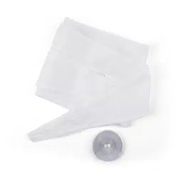
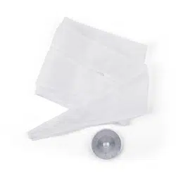
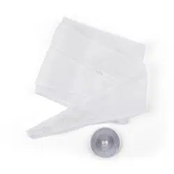
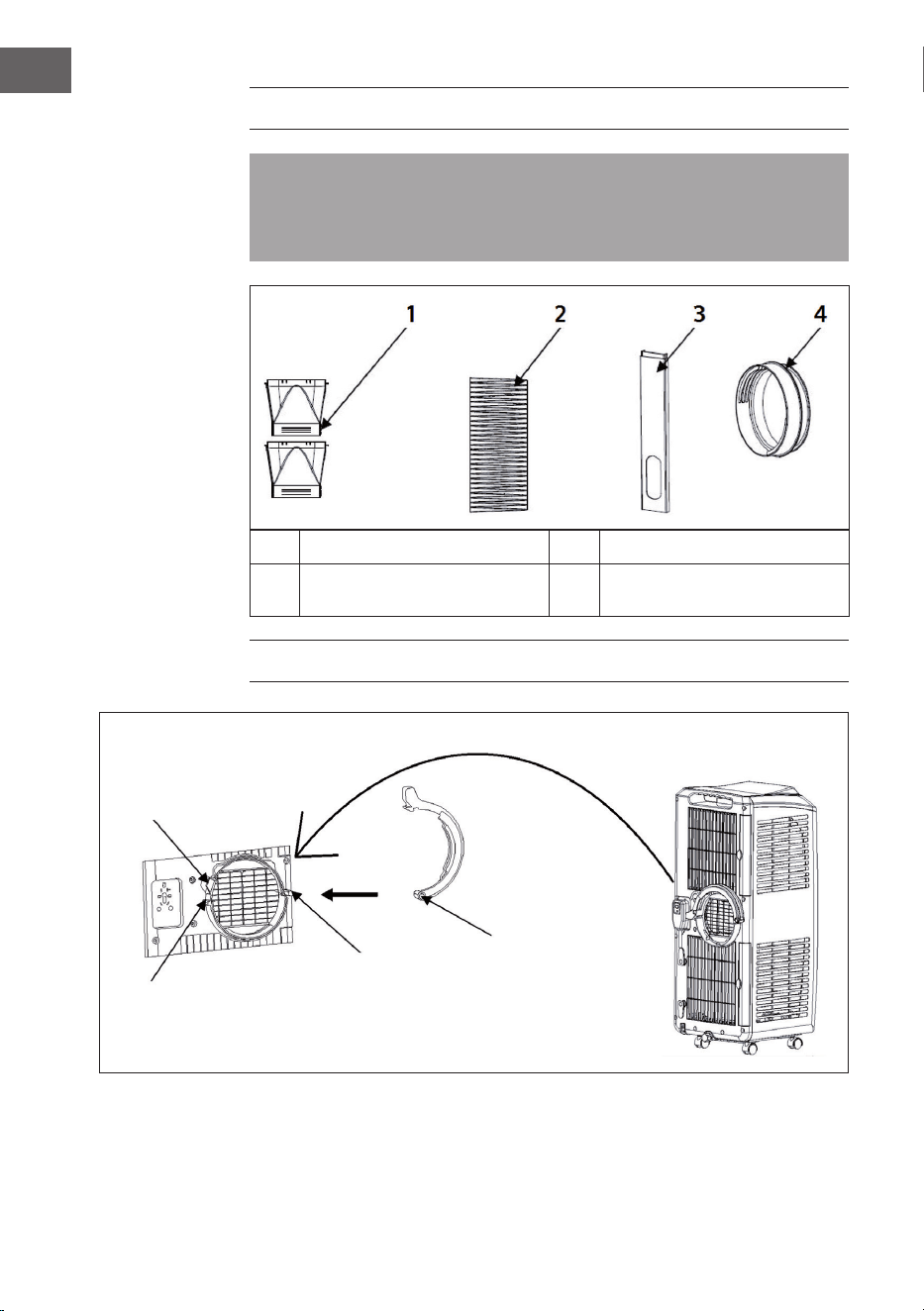
ÜBERSICHT ÜBER DIE BENÖTIGTEN TEILE
Diese Abdichtung ist nur kompatibel mit: (Art. Nr.) 10028187 und 10028188.
Die zur Montage benötigten Teile (hier 1, 2 und 4) sind im Lieferumfang der
kompatiblen Klimageräte 10028187 sowie 10028188 enthalten.
1 Auslass (2 Teile) 3 Fensterabdichtung
2 Auslassrohr 4
Reduziergewinde und
Schlauchhalterung
SCHRITT 1
Hängen Sie den Schlauch mit dem Reduziergewinde (Kunsstoffring) am Klimagerät
ein. Öffnen Sie dafür den Verschluss und klinken Sie den Ring ein. Schieben Sie
dazu den Verschluss zurück und lassen Sie den Schnappverschluss aufschnappen.
Verschluss
zurückschieben
Schnappverschluss
Schaft
Nabe

5
DE
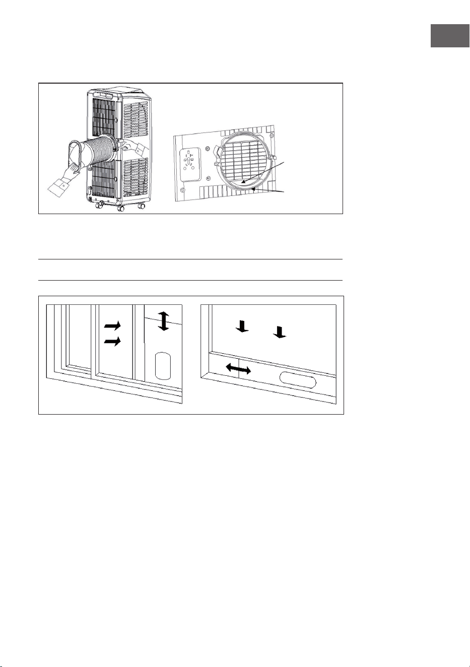
Schließen Sie dann wieder mit der an der Nabe aufgehangenen beweglichen
Klammer (zuschnappen lassen) und schieben Sie den Verschluss wieder darüber.
Der Schlauch muss hinter dem äußeren Ring eingehakt werden, damit man die
Verschlussklammer ohne Kraft zuschnappen lassen kann (siehe oben).
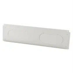
SCHRITT 2
Setzen Sie die Fensterabdichtung horizontal oder vertikal in einen Fensterspalt
ein. Wenn möglich (d.h. ohne dass irreparable Schäden entstehen und nur, wenn
der Rückbau problemlos erfolgen kann), nehmen Sie die Fensterdichtung an der
entsprechenden Stelle ab und führen Sie sie um den Einsatz herum. Verschrauben
Sie diesen gegebenenfalls mit der Führungsschiene des Fensters.
Nehmen Sie die beiden „Hälften“ des Luftauslass und schieben Sie diese
pfeilförmig in die Öffnung in der Fenster-Dichtung, so dass die widerhakenförmige
Einbuchtung beinahe einhakt. Klemmen Sie dann den Schlauch in die Mitte und
klappen Sie die beiden Hälften zusammen. Es sollte deutlich hör- und fühlbar
klicken. Das Klimagerät sollte bei diesem Schritt nicht weiter als 50 cm vom Fenster
entfernt stehen, damit etwaige Beschädigungen durch zu große Spannung oder
Knicke im Schlauch vermieden werden und das Klimagerät nicht umkippt.
Innenring
Außenring

6
EN
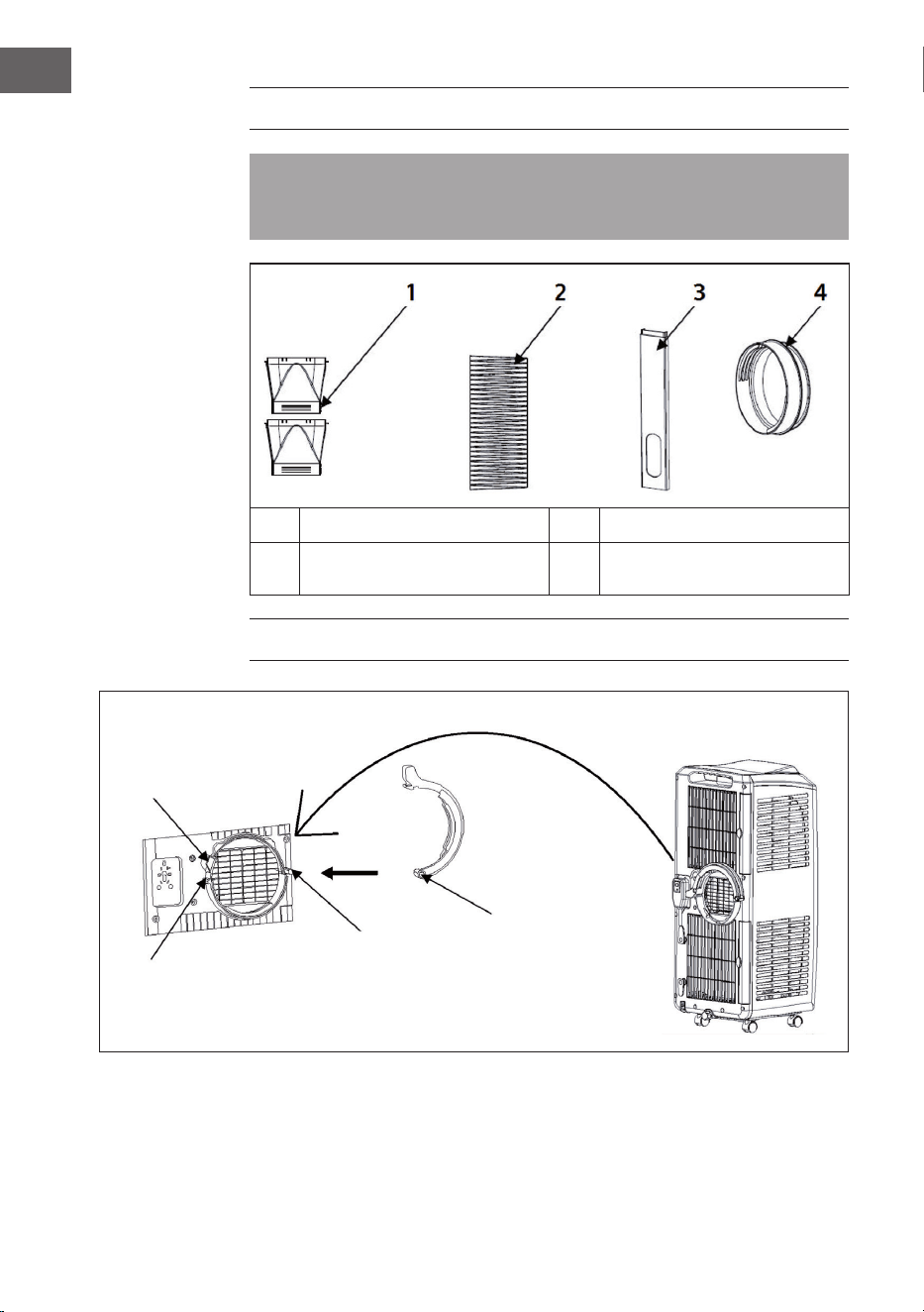
OVERVIEW OF THE PARTS REQUIRED
This seal is only compatible with: (part no.) 10028187 and 10028188. The parts
required for installation (here 1, 2 and 4) are included in the scope of delivery of
the compatible air conditioners 10028187 as well as 10028188.
1 Outlet (2 parts) 3 Window sealing
2 Outlet pipe 4
Reducing thread and hose
holder
STEP 1
Hook the hose with the reducing thread (plastic ring) onto the air conditioner. To
do this, open the catch and engage the ring. To do this, push the closure back and
allow the snap lock to snap open.
Push back the
lock
Snap closure
Shaft
Hub

7
EN
Then close again with the movable clip suspended from the hub (let it snap shut)
and slide the closure back over it.
The hose must be hooked behind the outer ring so that you can snap the locking
clip shut without force (see above).
STEP 2
Insert the window seal horizontally or vertically into a window gap. If possible
(i.e. without causing irreparable damage and only if removal can be done without
problems), remove the window seal at the appropriate place and guide it around
the insert. If necessary, screw it to the guide rail of the window.
Take the two „halves“ of the air outlet and slide them into the opening in the
window seal in an arrow shape so that the barbed indentation almost hooks into
place. Then clamp the hose in the center and fold the two halves together. There
should be a distinct audible and tactile click. The air conditioner should not be
more than 50 cm from the window during this step to avoid any damage caused
by excessive tension or kinks in the hose and to prevent the air conditioner from
tipping over.
Inner ring
Outer ring
8
ES
RESUMEN
Este aislamiento solamente es compatible con los modelos 10028187 y
10028188. Los com- ponentes necesarios para el montaje (en este caso, 1, 2
y 4) están incluidos en el envío de los climatizadores compatibles 10028187 y
10028188.
1 Salida (2 piezas) 3 Fijación de ventana
2 Tubo de salida 4
Rosca de reducción y
jación de manguera
PASO 1
Asegure la manguera al aparato de aire acondicionado con la rosca de reducción
(anilla plástica). Para ello abra la tapa y presione el anillo. Descorra para ello la
tapa y desenganche el cierre a presión.
Descorrer
la tapa
Cierre a presión
Eje
Buje
9
ES
Vuelva a cerrar con la grapa móvil del buje (enganchar) y vuelva a correr la tapa
por encima.
La manguera debe conectarse por detrás del anillo externo para poder enganchar
la grapa de cierre sin esfuerzo (ver arriba).
PASO 2
Coloque la jación de forma horizontal o vertical en el hueco de la ventana. Si
es posible (en caso de que no ocasione daños irreparables y sólo si se puede
desinstalar sin problemas) retire el burlete por el sitio indicado y colóquelo en
torno al accesorio. Opcionalmente, atorníllelo
con los rieles de la ventana.
Tome ambas mitades de la salida de aire y empújelas en forma de echa en la
abertura de la jación de la ventana de manera tal que la muesca en forma de
lengüeta casi enganche. Sujete entonces la manguera en el medio y enganche
ambas mitades juntas. Debería oírse y sentirse que se cierra. El aparato de aire
acondicionado no debería en éste paso estar a más de 50cm de la ventana para
evitar daños debidos a tensión o pliegues en la manguera y que el aparato de aire
acondicionado pueda volcarse.
Anillo interno
Anillo externo

10
FR
APERÇU
Cette bâche isolante est uniquement compatible avec : 10028187 et 10028188.
Les pièces nécessaires au montage (ici 1, 2 et 4) sont fournies dans l’emballage
des climatiseurs compa- tibles 10028187 et 10028188.
1 Sortie (en 2 parties) 3 Joint de fenêtre
2 Tuyau de sortie 4
Gaine d’évacuation et
support du tuyau
ÉTAPE 1
Fixer le tuyau au climatiseur avec la gaine d’évacuation (anneau en plastique). Pour
cela, ouvrir la fer- meture à clip et encliqueter la gaine. Faire coulisser la fermeture
à clip en arrière et laisser la fermeture se clipser.
Faire coulisser
la fermeture à clip
Fermeture à clip
Tige
Moyeu

11
FR
Puis la fermer de nouveau à l’aide des pinces mobiles du moyeu (laisser se clipser)
puis faire coulisser de nouveau le clip.
Le tuyau doit être encliqueté à l’arrière de l’anneau extérieur, an de pouvoir
clipser la pince de fermeture sans forcer (cf. ci-dessus).
ÉTAPE 2
Fixer le joint de fenêtre horizontalement ou verticalement le long d’un montant
ou d’une traverse de fenêtre. Si possible (c’est-à-dire si cela ne provoque aucun
dégât irréparable et seulement si le remontage peut être effectué sans problème),
enlever le joint de fenêtre à l’endroit correspondant et y placer le joint de
remplacement tout autour.
Se saisir des deux « moitiés » de l’évacuation d’air et les faire glisser selon les
èches dans l’ouverture de joint de fenêtre, de sorte que les cavités crénelées
s’encastrent. Puis attacher le tuyau au milieu et assembler les deux moitiés en les
encliquetant. Le bruit d’encliquetage doit être clairement audible. Le climatiseur,
à ce stade, ne doit pas se trouver à une distance supérieure à 50 cm de la fenêtre,
pour éviter tout dommage lié à une trop grande tension ou exion au niveau du
tuyau et pour éviter que le climatiseur ne se renverse.
Bague
intérieure
Bague
extérieure
12
IT
DESCRIZIONE
Questa guarnizione è compatibile solo con: 10028187 e 10028188. I componenti
necessari per il montaggio (qui 1, 2 e 4) sono contenuti nella consegna dei
limatizzatori compatibili 10028187 e 10028188
1 Scarico (2 parti) 3 Guarnizione nestra
2 Tubo di scarico 4
Riduttore di lettatura
e staffa di supporto tubo
FASE 1
Appendere il tubo al climatizzatore tramite il riduttore di lettatura (anello in
plastica). Aprire la chiusura e far scattare l’anello. Far scorrere la chiusura a scatto
no al suo inserimento.
Far scorrere la
chiusura a scatto
Chiusura a scatto
Albero
Foro rotante

13
IT
Chiudere di nuovo con il morsetto mobile (farlo scattare) appesa al foro rotante e
far scorrere la chiusura al di sopra.
Agganciare il tubo dietro l’anello esterno in modo che il morsetto di chiusura possa
scattare senza dover esercitare forza.
FASE 2
Installare la guarnizione orizzontalmente o verticalmente alla nestra. Se possibile
(ovvero senza causa- re danni irreparabili e solo se la guarnizione può essere
smontata senza problemi), rimuovere la guarnizi- one in gomma nel punto
corrispondente e metterla intorno. Se possibile, avvitarla ai binari della nestra.
Prendere le due „metà“ dello scarico dell‘aria e farle scorrere nell’apertura della
guarnizione della nestra. Fissare il tubo nel mezzo e assemblare le due metà:
si sentirà un clic. In questa fase il climatizzatore non deve essere a più di 50 cm
dalla nestra, in modo da evitare qualsiasi danno dovuto all’alta tensione o ad un
piegamento del tubo e in modo che il climatizzatore non si capovolga.
Anello interno
Anello
esterno

HERSTELLER
Manufacturer | Fabricante | Fabricant | Produttore
Chal-Tec GmbH, Wallstraße 16, 10179 Berlin, Deutschland (Germany).
IMPORTEUR FÜR GROSSBRITANNIEN
Importer for Great Britain | Importador para Gran Bretaña | Importateur
pour la Grande Bretagne | Importatore per la Gran Bretagna
Berlin Brands Group UK Limited
PO Box 42
272 Kensington High Street
London, W8 6ND
United Kingdom