1
121324
SUMMERSET GRILLS
Double Side Burner &
Double Side Burner Pro User Manual
Models: SB2
SB2L
SB2PRO
SB2PROL
DANGER
If you smell gas:
• Shut OFF gas supply to the appliance.
• Extinguish any open flame.
• Open lid.
• If odor continues, keep away from the appliance
and immediately call your gas supplier or your fire
department.
WARNING
• Do not store or use gasoline or other flamable liquids or
vapors in the vicinity of this or any other appliance.
• An LP cylinder not connected for use shall not be stored
in the vicinity of this or any other appliance.
ATTENTION:
INSTALLER: PLEASE LEAVE THESE INSTRUCTIONS WITH THE CONSUMER.
CONSUMER: PLEASE READ & RETAIN THESE INSTRUCTIONS FOR FUTURE
REFERENCE AND BEFORE INSTALLING OR OPERATING.
This appliance is designed as an “ATTENDED APPLIANCE”.
DO NOT leave this appliance burning when unattended.
2
SUMMERSET GRILLS
121324
WARNINGS
READ THIS MANUAL CAREFULLY AND COMPLETELY
BEFORE USING YOUR Side burner TO REDUCE THE
RISK OF:
Fire, burn hazard, personal injury or property damage,
improper installation or servicing electric shock.
THIS PRODUCT IS DESIGNED FOR OUTDOOR USE ONLY
Improper installation, adjustment, alteration, service or
maintenance can cause property damage, injury or death.
Read this manual thoroughly before installation, use, or
servicing of this product.
CODE AND SUPPLY REQUIREMENTS:
This side burner must be installed in accordance with local
codes and ordinances, or, in the absence of local codes,
with the latest National Fuel Gas Code (ANSI Z223.1/NFPA
54), or Natural Gas and Propane Storage and Handling
Installation Code (CSA-B149.1)
IF YOU SMELL GAS:
Shut off all gas supply lines to the side burner. Extinguish
any open ames. Carefully open the lid. Remember, it may
be extremely hot! If odor continues, keep everyone away
from the side burner and immediately call your gas supplier
or your re department.
EXPLOSION HAZARD:
DO NOT use the side burner as a storage area for amma-
ble
materials. Keep area clear and free from combustible
materials, gasoline, and other ammable vapors and
liquids. Failure to do so can result in death, explosion, or
re. An LP cylinder not connected for use shall not be
stored in the vicinity of this or any other appliance.
The outdoor cooking gas appliance and its dedicated
shutoff valve must be disconnected from the gas supply
piping system during pressure testing of that system at test
pressures in excess of .5 psi (3.5kPa).
The outdoor cooking gas appliance must be isolated from
the gas supply piping system by closing its dedicated
manual shutoff valve during any pressure testing of the gas
supply piping system at test pressures equal to or less than
.5 psi (3.5kPa).
WARNING
NEVER cover slots, holes, or passage in the oven bottom
or cover an entire rack with material such as aluminum foil.
Doing so blocks air ow through the oven and may cause
carbon monoxide poisoning.
Aluminum foil linings may trap heat causing a re hazard.
CALIFORNIA PROPOSITION 65
WARNING
This product is designed to operate with one of the
following fuel sources: Liquid Propane or Natural Gas.
The fuel used to operate this product, and the products of
combustion of such fuel, can expose you to chemicals
including Benzene which is known to the State of California
to cause cancer, birth defects and other reproductive harm
and Carbon Monoxide which is known to the State of
California to cause birth defects or other reproductive harm.
(For more information go to: www.p65Warnings.ca.gov.)
This appliance is designed as an “ATTENDED
APPLIANCE”. DO NOT leave this appliance
burning when unattended.
Minimum Ambient Operating Termperature:
0°F (-17.8 °C)
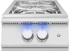
IMPORTANT:
This barbecue/appliance is equipped with backlit LED
knobs that illuminate and turn red when the burner is
switched to the “on” position (when the side burner is
plugged into a power source and the switches are turned
on). However, the color change of the LED knobs
should not be relied upon as a sole indicator of gas
ow to the burner. The LED lights signal the “on” position
of the knob but do not conrm that gas is owing.
For Safety:
• Always conrm burner ignition by observing the burner
ame directly.
• If you do not see a ame, turn the burner off, wait ve
minutes, and try reigniting.
• Never leave the side burner unattended while in use.
* Pertains to SB2PRO model only
3
SUMMERSET GRILLS
121324
TABLE OF CONTENTS
To view on your phone, scan the QR
code on your smart phone’s camera app.
(For Android devices, use Google Lens.)
PART #: SB2
SB2L
SB2PRO
SB2PROL
THANK YOU
Thank you for your purchase. We’d like to welcome you to
the Summerset Side burners family of luxury outdoor kitch-
en products and look forward to being a part your home for
years to come. As a family business with over 20 years of
industry experience, we aim to deliver exceptional quality
and personal service. Welcome to the Summerset Side
burners family and we hope you love your new side burner!
FOR YOUR RECORDS
Please record the following information and refer to it when
contacting Summerset Side burners or an authorized
dealer. The serial number is located on the rating plate.
The rating plate is located on the exterior basin of the side
burner (re box) and on the underneath side of the drip tray
(select models only).
INSTALLER
Please leave this manual for the owner
Serial Number:
Model:
Date of Purchase:
Place of Purchase:
For warranty information and to register your side burner
visit, amddirect.com/register
(Natural Gas & Liquid Propane Gas Congurations)
Warnings 2 & 4
Before Operating 5
Installation 6-7
Gas Requirements 8-10
Custom-Built Island 11
Lighting the Side burner 12
Operating/Maintenance Tips 13-14
Line Drawings 15
Replacement Parts 16
Illustrated Parts 17
Warranty 18
Gas Pipe Sizing Chart 19
Vent Hood Information 20
Refrigeration 21
Care & Cleaning 22

4
SUMMERSET GRILLS
121324
SAFETY AND INSTALLATION WARNINGS
• Please read all instructions before installation or operating your side burner to prevent injury and appliance damage
• All side burners will get hot during use. Use extreme caution when operating the side burner
• Do not touch hot surfaces. Always use the handle to place or remove the side burner lid.
• Never use dented, rusty or damaged propane cylinders. Never store additional or empty propane cylinders in the side
burner cabinet or in the vicinity of this or any other appliance
• Close supervision is necessary when this or any appliance is used near children. Keep children away from the side
burner during operation and until the side burner has cooled off
• Children should never be left alone or unattended in an area where a side burner is located. Place your side burner
well away from areas where children play. Do not store items that may interest children in or around the side burner, in
the cart, or in the masonry enclosure
• Never move the side burner when hot. When in use, portions of the side burner are hot enough to cause severe
burns.
• Always maintain the required clearances from combustibles as detailed. The side burner is designed for outdoor use
only. Never use in a garage, building, shed, breezeway, or other enclosed area. Do not use this side burner under any
unprotected overhead combustible construction
• Side burners are not designed or certied for and are not to be installed in or on recreational vehicles, portable trail-
ers, boats or any other moving installation
• Always have an ABC Fire Extinguisher accessible — never attempt to extinguish a grease re with water or other
liquids
• Storing your side burner: Store your side burner in a well-ventilated area. If stored indoors, detach and leave L.P. cyl-
inder outdoors in a well-ventilated area away from heat and away from where children may tamper with it
• Keep any electrical supply cord and the fuel supply hose away from any heated surfaces. Electrical cords should be
placed away from walkways to avoid tripping hazard
• Do not repair or replace any part of the side burner unless specically recommended in this manual. Other service
should be performed by a qualied technician
• If the side burner is installed by a professional installer or technician, be sure that he/she shows you where your gas
supply shut-off is located. All gas lines must have a shut-off that is readily and easily accessible. If you smell gas,
check for gas leaks immediately. Check only with a soap and water solution. Never check for gas leaks with an open
ame
• Do not twist the gas supply hose
• Inspect the L.P. gas supply hose prior to each use of the side burner. If there is evidence of excessive abrasion or
wear, or the hose is cut, it must be replaced before using the side burner
• The use of accessories, regulators, or components not recommend by the appliance manufacturer may cause injuries
and will void warranty
• Never light the side burner with the hood closed and be certain the burners are positioned and seated over the gas
valves and on the burner support
• Never lean over the cooking surface when lighting or operating the side burner
• Use barbecue tools with wood handles and insulated oven mitts when operating the side burner
• Be sure the gas supplied to the side burner conforms to the model you purchased. A natural side burner requires nat-
ural gas to operate; a liquid propane side burner requires liquid propane to operate
• Never connect the appliance to an unregulated gas supply line. Side burners operated without a regulator are unsafe
and will not be serviced until installed properly and safely. Unsafe operation without a gas regulator will void the war-
ranty
• Side burners operating with natural gas must be installed with the NG regulator supplied with the unit and set to 4.0”
of water column pressure
• Side burners operating with Liquid Propane must be installed with an LP regulator and set to 11” of water column
pressure
WARNINGS

5
SUMMERSET GRILLS
121324
CHECK FOR SHIPPING DAMAGE:
VISIBLE DAMAGE
If your shipment arrives with visible damage to the box/
carton, be sure the damage is noted on the bill of freight
or express receipt and signed by the person making the
delivery. File claim for damages immediately, regardless of
the extent of damage.
CONCEALED DAMAGES
If damages are unnoticed until the side burner is unpacked,
notify the transportation company or carrier immediately
and le a concealed damage claim with them. This should
be done within (5) days of the delivery date. Be sure to hold
on to the box/carton for inspection. We cannot assume
responsibility for damage or loss incurred in transit.
IMPORTANT NOTES:
BE MINDFUL OF WIND DIRECTION
Using your side burner in windy conditions may disrupt
the front-to-back air ow that the side burner is designed
for. If you notice that the temperature gauge fails to rise
while side burnering with all burners on high and the hood
closed, then be careful. If wind keeps the heat from exit-
ing the rear of the side burner, then the control panel and
knobs could become extremely hot. Your side burner pulls
air in through its front and vents hot gases out the rear
hood; do not side burner if wind is entering the rear hood of
the side burner.
GAS LINE LENGTH
Keep all gas supply lines as short as possible. Gas lines
lose pressure over distance and with each elbow or “T”
tting added. This drop in pressure affects side burner
performance.
*See Gas Pipe Sizing Chart on page 19
PROPER LEVELING
PROPER LEVELING DURING INSTALLATION IS
CRITICAL. A Side burner THAT IS OUT OF LEVEL WILL
CAUSE ERRATIC BURNER COMBUSTION AND
INEFFICIENT, UNEVEN HEATING. THE Side burner
SHOULD BE LEVEL IN ALL DIRECTIONS. ADJUST-
MENTS MAY NEED TO BE MADE EACH TIME WHEN
MOVING A FREESTANDING UNIT.
CONSTRUCTION ZONES
Keep all stainless steel products away from construction
zones. Construction debris such as (but not limited to)
stone dust, stucco, and lime dust could damage or
permanently discolor stainless steel products. Keep all
caustic chemicals including chlorine and pool cleaning
products away from stainless steel at all times.
BEFORE OPERATING
UNPACKING YOUR Side burner
Included with your TRL Pro side burner are the following
loose items:
Cooking Grates: SB2(1), SB2PRO(1)
Drip Tray: SB2(1), SB2PRO(1)
Main Burners: SB2(2), SB2PRO(2)
Side Burner Cover: SB2(1), SB2PRO(1)
Set of orices
• If side burner is factory set LP, NG orices will be
included
• If side burner is factory set NG, LP orices will be
included
• The drip tray will be at the bottom of the unit and will
slide into the drip tray support brackets.
• Rotisserie spit storage underneath the drip tray
6
SUMMERSET GRILLS
121324
INSTALLATION
N
o
n
- Co
m
bu
st
ib
le
A
B
C
A
M
e
ta
l
S
tud
s
Ventilation
Ventilation
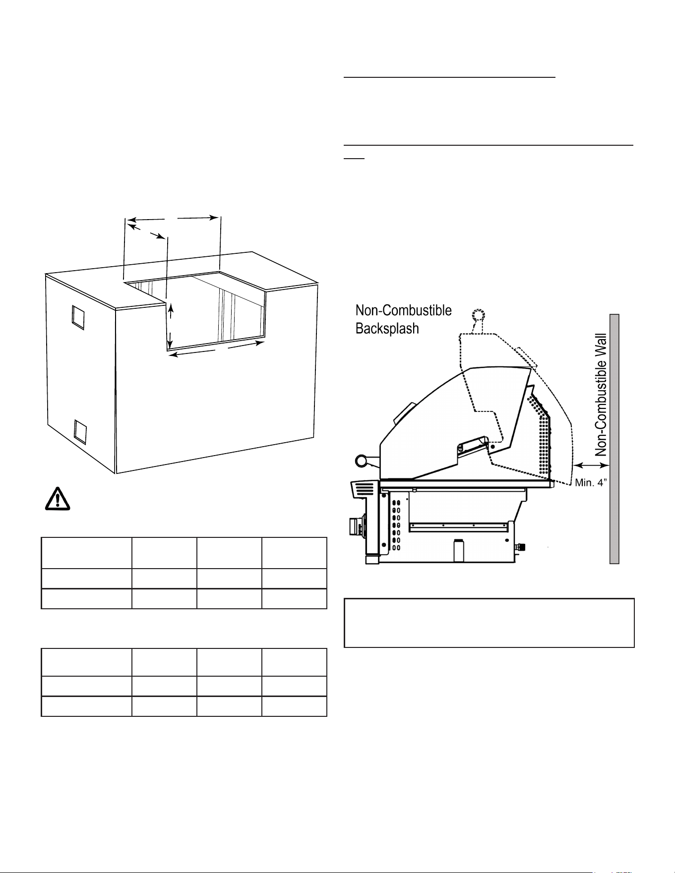
Figure 1
SIDE BURNER
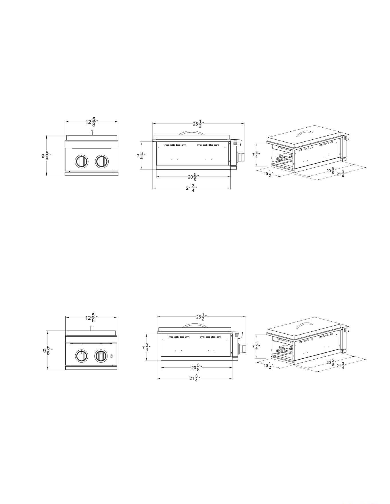
MODEL A: WIDTH B: DEPTH C: HEIGHT
SB2 10-3/4” 20-3/4” 8”
SB2PRO 10-3/4” 20-3/4” 8”
SIDE BURNER
MODEL A: WIDTH B: DEPTH C: HEIGHT
SB2 12-5/8” 25-1/2” 9-5/8”
SB2PRO 12-5/8” 25-1/2” 9-5/8”
ISLAND CUT OUT DIMENSIONS
OVERALL PRODUCT DIMENSIONS
ALL BBQ ISLANDS MUST BE MANUFACTURED
FROM “NON COMBUSTIBLE” MATERIALS.
The TRL Pro can be used as a built-in unit or with a Sum-
merset side burner cart. For installation as a built-in, it
requires a non-combustible island or enclosure. Use Figure
1 and Table 1 as a guide.
It is recommended to use cement board with steel studs
and proper ventilation per local codes. A minimum 4-inch
vent size is required, one at the top and one at the
bottom to provide free owing air keep the island cool
during operation of the side burner.
Table 1
Table 2
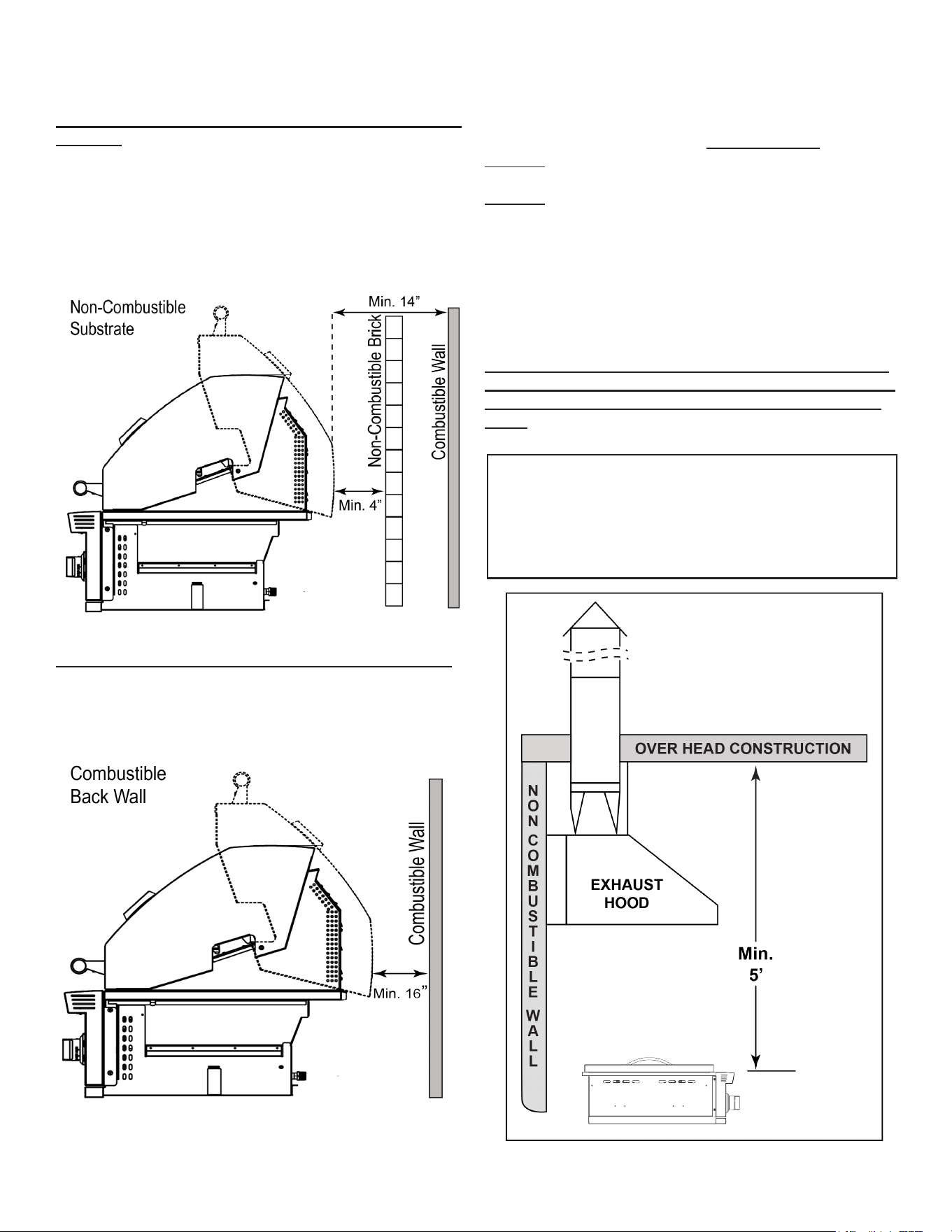
The side burner must have a minimum of 14” clearance
from the right side, left side and rear (back) of the side
burner from a protected combustible wall. Refer to Figure 3.
IMPORTANT NOTE:
Clearance from the side burner and a non-combustible
wall
(i.e. brick wall, see Figure. 2). The side burner requires a
minimum of 4” clearance from the right side, left side and
rear (back) of the side burner from any non-combustible
wall. This allows for proper ventilation and helps prevent
dangerous overheating.
If a non-combustible backsplash exists, it must have a
minimum of a 4” clearance from the rear of the side burner
(to allow for proper ventilation and help prevent dangerous
overheating. Clearance Figure 2).
MINIMUM SIDE BURNER CLEARANCES:
Minimum clearances between the side burner and any
side wall or rear wall must fall within one (or more) of the
following:
Figure 2
IMPORTANT NOTE:
This 4” backsplash clearance must rst be met prior to
any non-combustible walls beginning behind it.
Note: Refer to page 10 for Custom Built-In Enclosures/
Islands when building.
7
SUMMERSET GRILLS
121324
Clearance from the side burner and protected combus-
tible wall (i.e. A non-combustible wall in front of a combus-
tible wall to serve as a barrier. This can be accomplished
by brick or a metal stud nished with non-combustible
substrate.
See Figure 3). The side burner must have a minimum of
14” right, left and rear clearance from the protected com-
bustible wall. ( 4” non-combustible material clearance, plus
an additional 10” clearance between the side burner and
protected wall.)
INSTALLATION
Figure 3
Clearance from the side burner and combustible wall
(Clearance Figure 4). The side burner must have a mini-
mum
clearance of 16” from the right side, left side and rear of the
side burner to any combustible wall.
Figure 4
OVERHEAD CONSTRUCTION AND EXHAUST HOOD
REQUIREMENTS
This side burner is designed for outdoor use only.
DO NOT use this side burner inside a building, garage, or
enclosed area.
DO NOT use this side burner in or on a recreational vehicle
or boat.
When installing this side burner in a combustible surround,
a
Summerset Side burners insulating jacket/side burner liner
must be used.
A minimum ve (5) foot clearance is required between the
countertop and the overhead construction.
When the side burner is installed under a combustible
overhead construction, the area above the cooking sur-
face of the side burner must be used with an exhaust
hood. The exhaust hood provides the protection for the
combustible overhead construction. See Figure 5.
IMPORTANT NOTE:
• DO NOT use this appliance under unprotected
combustible overhead construction.
• When installed under overhead non-combustible
construction, an exhaust hood is highly recommended.
Figure 5
When using an exhaust hood, the area above
the cooking surface of the side burner must be
covered with a hood larger than the cooking area
of the side burner, and the blower must produce a
minimum of 1000 CFM (cubic feet per minute) for
proper outdoor exhausting. Additionally, ensure
that the exhaust hood and all overhead construc-
tion materials are non-combustible.
8
SUMMERSET GRILLS
121324
GAS REQUIREMENTS
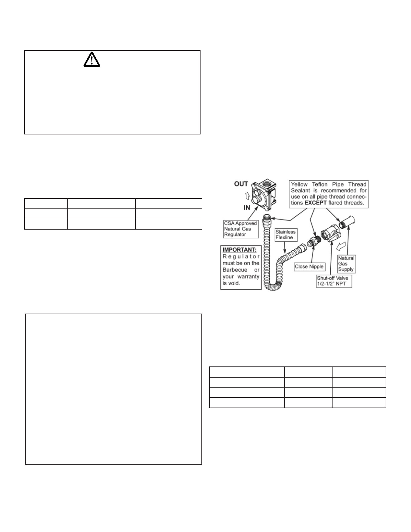
GAS LINES
Never connect a gas line directly to the side
burner. A pressure regulator must be installed
on all gas equipment. Removing or failing to
install the pressure regulator can result in re
and serious personal injury and will void the
warranty
WARNING
Ensure the gas supplied meets the minimum pressure
requirements. See Table 3 for gas requirements measure in
Water Column (W.C.) pressure.
GAS PRESSURE REQUIREMENTS
MAIN & REAR BURNER BTU INFORMATION
Pressure Natural Gas Propane Gas
Min. Inlet 4.0” WC (1.00.kPa) 10.0” WC (2.49 kPa)
Max. Inlet 7.0” WC (1.74 kPa) 14.0” WC (3.48 kPa)
Burner Type SB2 SB2PRO
Front Burner BTU 12,000 12,000
Rear Burner BTU 12,000 12,000
Total BTU 24,000 24,000
Table 3
Table 4
IMPORTANT:
All electrical outlets in the vicinity of the side
burner must be properly grounded in accor-
dance with local codes, or in the absence of
local codes, with the National Electrical Code,
ANSI/NFPA 70 or the Canadian Electrical Code,
CSA C22.1, whichever is applicable.
Keep all electrical supply cords and fuel supply
hoses away from any heated surface.
NOTE: Both the regulator and burner orices have been
tuned for the type of gas specied on the rating plate.
Converting to a different type of gas requires a conversion
kit. Conversion kits are included with this side burner and
located with the manual. Converting gases may require
additional parts not included with this side burner. (See
Gas Conversion section for details).
NATURAL GAS REQUIREMENTS
• Summerset Side burners recommends that only qual-
ied professionals perform the required plumbing on
this product.
• Check the Rating Plate to make sure the gas
supply you are hooking up to is the gas type the side
burner is manufactured for.
• To ensure satisfactory performance, the gas supply
line must be sized to accommodate the total BTU
requirements of all the gas-red equipment that will be
connected to that line.
• In no case should pipe less than 1/2” inside diameter
or 1” outside diameter ever be used to connect this
product.
NOTE: DO NOT use any tape, pipe dope or threading
compound on any are tting. This will cause a clog
in the regulator and prevent your side burner from
functioning properly.
CONNECTING TO THE NG REGULATOR
Figure 6
Circuit Board Power:
LED strip:
SB2
1.6w
0.8w
SB2PRO
2w
0.8w
9
SUMMERSET GRILLS
121324
Figure 7
GAS REQUIREMENTS
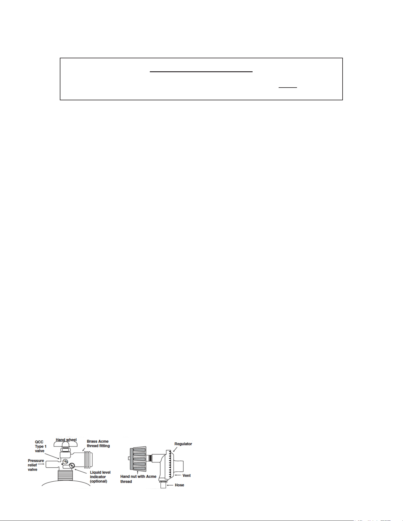
SAFE USE AND MAINTENANCE OF PROPANE GAS CYLINDERS
IMPORTANT FOR YOUR SAFETY
READ AND FOLLOW ALL WARNINGS PROVIDED WITH THE PROPANE GAS CYLINDER.
When operating a Propane gas cylinder, these instructions and warnings MUST be observed.
FAILURE TO DO SO MAY RESULT IN A SERIOUS FIRE OR EXPLOSION
CYLINDER/CONNECTOR REQUIREMENTS
a. Propane gas cylinders, valves and hoses must be
maintained in good condition and inspected before
each use of an appliance. They must be replaced if
there is any visible damage. If the hose is cut or shows
any excessive abrasion or wear, it must be replaced
before using the appliance. (See section e.)
b. This unit, when used with a portable cylinder, should be
connected to a standard 5-gallon (20 lb.) propane gas
cylinder equipped with a listed overlling prevention
device.
c. Cylinder dimensions should be approximately 12”
(30.5cm) in diameter and 18” (45.7cm) high. Cylin-
ders must be constructed and marked in accordance
with the U.S. Department of Transportation (D.O.T.)
Specications for LP-Gas Cylinders, or the standard
for Cylinders, Spheres, and Tubes for Transportation of
Dangerous Goods and Commission, CAN/CSA-B339,
as applicable.
d. The cylinder used must include a collar to protect the
cylinder valve, and the cylinder supply system must be
arranged for vapor withdrawal.
e. The pressure regulator and hose assembly used must
match the specication for Type I by ANSI Z 21.58/CGA
1.6 (See Figure 7)
f. The propane gas cylinder valve must be equipped with
a cylinder connection device, described as Type I in the
standard dened in paragraph “e” above. This device
is commonly describes as an Acme thread coupler.
g. If the propane gas cylinder comes with a dust cap,
place the dust cap on the cylinder valve outlet
whenever the cylinder is not in use.
COUPLER OPERATION
To connect the regulator/hose to the Propane gas
cylinder valve tting:
Press the hand nut on the regulator over the Acme thread
tting on the cylinder valve. Turn the hand nut clockwise
to engage the threads and tighten until snug. The pliers of
a wrench should not be necessary. Only cylinder marked
“Propane” may be used.
To Disconnect:
Turn the hand nut counterclockwise until detached. See
Figure 7.
IMPORTANT: Before using the unit, and after each time
the cylinder is removed and reattached check the hose for
wear (See section “a”) and check all connections for leaks.
Turn OFF the unit valves and open the main cylinder valve,
then check connections with soapy water. Repair any leaks
before lighting the unit.
CAUTION: Always turn the Propane cylinder main valve
OFF after each use, and before moving the unit and
cylinder or disconnecting the coupling. This valve must
remain closed and the cylinder disconnected while the
appliance is not in use, even though the gas ow is stopped
by a safety feature when the coupler is disconnected.
Carefully inspect the hose assembly each time before
the gas is turned ON. A cracked or frayed hose must be
replaced immediately.
If the appliance is stored indoors, the cylinder must be
disconnected and removed. Disconnected cylinders must
be stored outdoors, out of reach of children, with threaded
valve plugs tightly installed, and must not be stored in a
building, garage, or any other enclosed area.
FOR YOUR SAFETY
• DO NOT store a spare Propane gas cylinder under or
near this appliance.
• NEVER ll the cylinder beyond 80% full.
• IF THE INFORMATION IN SECTIONS “a” AND “b”
IS NOT FOLLOWED EXACTLY, A FIRE CAUSING
DEATH OR SERIOUS INJURY MY OCCUR.
For proper ventilation and enclosure requirements,
see the Enclosure Installation and Ventilation
Requirements on pages 6 and 11.
10
SUMMERSET GRILLS
121324
PROPANE GAS TANK REQUIREMENTS
FILLING AND REFILLING LP GAS CYLINDERS
All purging and relling of LP gas cylinders must be
performed by qualied personnel in the LP gas
industry. Never store a spare LP gas cylinder under or
near this appliance.
Never ll the LP gas cylinder beyond 80 percent full.
Failure to follow these instructions may result in
explosion, personal injury or death.
LP side burner models are designed for use with a stan-
dard 20 lb. liquid propane gas (LP) tank with type (1) valve
connections. (Not included)
A professional plumber or Gas technician can adapt an LP
side burner to your home’s bulk LP gas supply. Connecting
a side burner to a home propane tank is not recommended
because of the risk of losing large amounts of propane.
Even if you turn off the side burner supply, leaks can still
happen, and pests like squirrels and mice are known to
chew on propane lines.
A dented or rusty LP tank may be hazardous and should be
avoided. If in doubt, have it checked by your LP
supplier. Always check for leaks after every LP tank
change. (See Checking For Leaks)
LP Tanks must be stored outdoors in a well-ventilated area
out of the reach of children. If your side burner is stored
indoors, the LP tank must be stored outside, in upright posi-
tion and away from excessive heat.
IMPORTANT:
All installation and all installation parts must conform to
local codes with the National Electrical Code,
ANSI Z223.1/ NFPA 70 latest edition and the National
Fuel Gas Code ANSI Z223.1/NFPA 54 in the U.S. and
CGA-B149.1/.2 in Canada
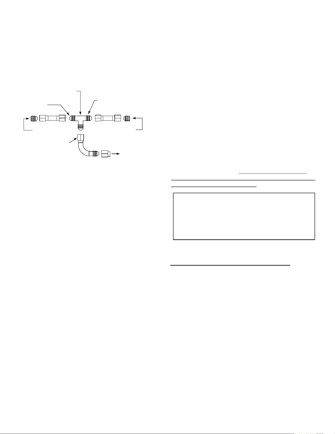
CONNECTING TO A SIDE BURNER
You will need a ‘T’ adapter tting (not provided) or similar
connection to connect a single gas line to both a side
burner and a side burner. We recommend a licensed gas
technician install all gas lines. See below Figure 8 for
installation of a ‘T’ adapter.
From Side Burner
To Propane Tank or
Natural Gas Connection
3/8” Fittings
From Grill
To grill, located underneath
and behind grill
To side burner, located underneath
and behind burner
3/8” threaded “T” adapter
LIQUID PROPANE INSTALLATION
IMPORTANT:
Ventilation is required in the enclosure and recommended
on opposite sides. Liquid Propane is heavier than Natural
Gas and vents should be located near the bottom of the
enclosure. In some applications, there will be free air space
at the bottom of the enclosure which can act as the ventila-
tion.
TESTING FOR LEAKS
Create a soapy water solution of 1 part soap and 3 parts
water. Conrm that all control knobs are in the off position.
Turn on the fuel supply.
For Natural Gas, turn the valve handle ¼ turn to align with
the gas ow. For LP, turn the cylinder valve counter
clockwise one full rotation. Apply the soap solution
generously by paint brush or squirt bottle on all connections
and ttings. If bubble appear to grow on any of the
connections, you have a gas leak. IMMEDIATELY turn OFF
the gas supply. Wash off the soapy solution with cold water
and dry. Tighten the loose joint or replace the faulty part
with manufacturer-recommended replacement parts.
DO NOT attempt to repair the L.P. cylinder valve if it is
damaged. The only way to safely resolve a damaged
cylinder is to replace it by calling an authorized gas
appliance service technician or an LP gas dealer. Repeat
the leak test to ensure that no leaks are present. Do not
use the appliance until the leak is corrected.
GAS REQUIREMENTS
11
SUMMERSET GRILLS
121324
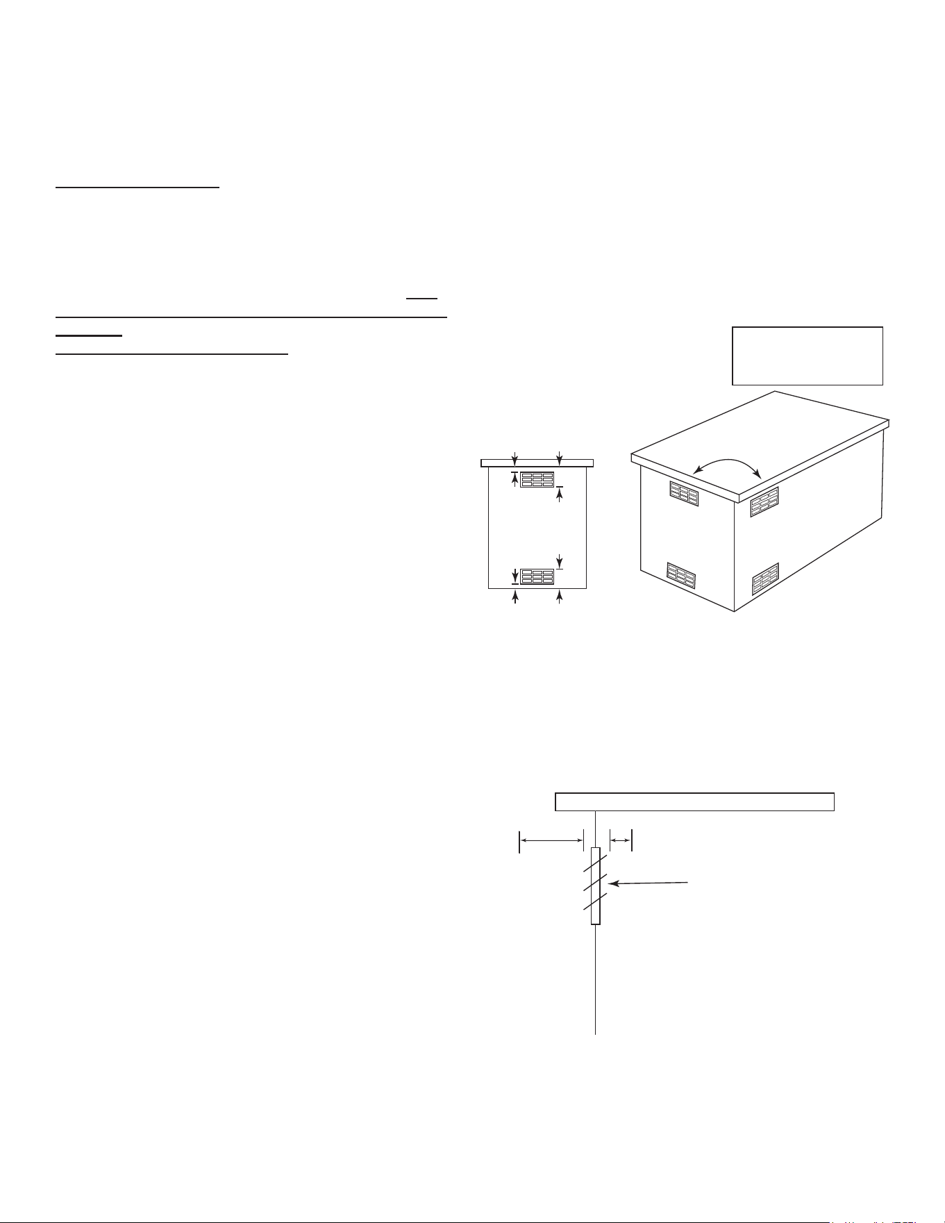
CUSTOM-BUILT ENCLOSURES/ ISLANDS
VENTILATION RECOMMENDATIONS
FOR ALL ENCLOSURES
FOR ALL GAS TYPES:
Natural Gas, Household Propane or LP Cylinder/Tanks
FOR YOUR SAFETY, you should provide the openings
listed below for replacement air and ventilation of the
side burner enclosure (i.e. in case of possible gas
leaks from connections or LP tanks/cylinders). Fail-
ure to do so may result in a re or explosion causing
property
damage, bodily injury or death.
One side of the enclosure shall be kept completely
open to the outside OR ventilation openings MUST be
provided:
• Each opening should have a minimum of 10 sq. in.
of free area. The openings should be equally sized,
providing a total of 40 sq. in.
• Two openings should be in the side walls of the
enclosure, at the top and spaced a minimum of 90º
from each other. The openings should begin 1” or less
below the countertop edge and end no more than 5”
below the countertop edge. See Figure 9.
• Two openings should be in the side walls of the
enclosure, at the bottom (oor level) and spaced a
minimum of 90º from each other. The openings should
begin 1” above the oor level and end no more than 5”
above oor level.
• The openings must remain unobstructed:
The clearance between the openings and any items
outside of the enclosure is a minimum of 6”. The
clearance between the openings and any items withing
the enclosure is a minimum of 2”. This provides free
owing air inside and outside the enclosure to keep
the island cool during operation of the side burner. See
Figure 9.
• An appliance is considered to be outdoors if installed
with shelter no more inclusive than with walls on three
sides, but with no overhead cover; all openings must
be permanently open; sliding doors, garage doors,
windows, or screened openings are not considered as
permanent openings.
• An appliance is considered to be outdoors if installed
with shelter no more inclusive than within a partial
enclosure that includes an overhead cover and no
more than two sidewalls. The sidewalls may be paral-
lel, as in a breezeway, or at right angles to each other;
all openings must be permanently open; sliding doors,
garage doors, windows, or screened openings are not
Min. 90˚
1” Min.
5” Max.
Min. (4) Openings
10 sq.in. of free
area min. (each)
Total= 40 sq. in.
Countertop
Ventilation Requirements
• Minimum 4 openings (2 per side wall
spaced at 90°)
• Top openings: within 5” of countertop
• Bottom openings: within 5” of floor
• Each vent opening: Min. 10 sq. in of
free area (Total to = 40 sq. in.)
Vent openings must be kept
clear and free at all times.
5” Max.
1” Min.
Enclosure Side View
Vent Opening
2” Min.
6” Min.
• 6” Minimum clearance in front of all
vent openings to any items outside
the enclosure
• 2“ Minimum clearance in front of all
vent openings to any items inside
the enclosure
UNOBSTRUCTED VENT OPENINGS
VENTILATION RECOMMENDATIONS
Figure 9
Figure 10
considered as permanent openings.
• An appliance is considered to be outdoors if installed
with shelter no more inclusive than within a partial
enclosure that includes an overhead cover and three
sidewalls, as long as 30% or more of the horizontal
periphery of the enclosure is permanently open. All
openings must be permanently open; sliding doors,
garage doors, windows, or screened openings are not
considered as permanent openings.

12
SUMMERSET GRILLS
121324
OPERATION
READ INSTRUCTIONS
BEFORE LIGHTING
ELECTRONIC SPARK IGNITION
CAUTION: Keep your face and body away from
the side burner top when lighting
Open the hood before lighting; do not attempt
to ignite burners while hood is closed.
Make sure gas supply is turned ON.
Make sure burner control knobs are in the “OFF”
position. DO NOT turn on more than one valve at
a time for initial ignition.
1. Press in the control knob then slightly turn
the knob counterclockwise while still pressing
inward.
2. Hold in the above position for 5 seconds
allowing the gas to reach the manifold.
3. While the knob is pushed in, you will hear a
consistent clicking sound from the electronic
ignition.
4. If burner does not light in 5 seconds, turn the
burner control(s) OFF, wait 5 minutes, and
repeat steps 1-3. Gas may need to be primed
several times to ll gas manifold ignition.
5. After ignition, set the knob to the desired
setting.
1. Follow steps 1-3
2. Place either a burning long-barrel butane
lighter or a burning long-stem match near the
manual ash tube to the right of the side burn-
er. For back burners, hold the ame against
the surface of the back burner.
3. Hold the lighter or match ame at the top of
the manual ash tube for ve (5) seconds,
or, next to the back burner. Then depress the
appropriate control knob and while pressing
turn it counterclockwise to the HI position.
Remove the lighter or match when the burner
lights and release the control knob.
4. If burner does not light in 5 seconds, turn the
burner control(s) OFF, wait 5 minutes, and
repeat steps 1-3. Gas may need to be primed
several times to ll gas manifold ignitionAfter
ignition, set the knob to the desired setting.
MANUAL (MATCH LIGHT) IGNITION
READ INSTRUCTIONS
BEFORE LIGHTING
CAUTION: Keep your face and body away from
the side burner top when lighting
Open the hood before lighting; do not attempt to
ignite burners while hood is closed.
Make sure gas supply is turned ON.
Make sure burner control knobs are in the “OFF”
position. DO NOT turn on more than one valve at
a time for initial ignition.
SHUT OFF INSTRUCTIONS
1. To shut OFF the side burner, depress each valve control knob and
while pressing turn clockwise to the“OFF” position.
2. Always close the valve from the gas supply after each use of the
side burner.
This appliance is designed as an “ATTENDED APPLIANCE”.
DO NOT leave this appliance burning when unattended.
Check and clean burner/venturi tubes for insects and insect
nests. A clogged tube can lead to a re beneath the side burner.

13
SUMMERSET GRILLS
121324
PRE-HEATING THE Side burner
Pre-heating your side burner every time you use it is ex-
tremely
important. Pre-heating allows the briquettes to properly
heat up, providing more even and more consistent
cooking results. Pre-heat your side burner by igniting all
main
burners. Then close the hood and allow the side burner to
heat for 10 to 15 minutes, the hood thermometer should
reach
approximately 450°. Once you’ve reached your desired
pre-heat temperature, turn OFF the burners that you won’t
be using to cook your food. Remember, surface
temperature can be up to 200° higher.
OPERATION & MAINTENANCE TIPS
SHUT OFF INSTRUCTIONS
1. To shut off the unit, depress each valve control knob
and while pressing turn clockwise to the“OFF” position.
2. Always close the valve from the gas supply after each
use of the unit.
NOTE:
When using a portable Propane tank: Propane tanks are
equipped with a safety shutdown device that may cause
low or no gas pressure/ ame at the burners if operating
and lighting instructions are not followed exactly.
ADJUSTING YOUR BURNER TO A LOWER SETTING
• Make sure the side burner is cool
• Remove the racks so you can see the ames while
• adjusting the burners
• Light the burner
• Turn the burner to “LOW”
• Pull off the control knob
• Use a at head screw driver and adjust the “gold
athead screw” in the valve to the proper ame height
MAINTENANCE TIPS
Stainless steels need to be cleaned for aesthetic
considerations and to preserve corrosion resistance.
Stainless steel is protected from corrosion by a thin layer of
chromium oxide. Oxygen from the atmosphere combines
with the chromium in the stainless steel to form this passive
chromium oxide lm that protects from further corrosion.
EXTERIOR STAINLESS STEEL CLEANING
Fill a bucket with warm water and soap (Dawn or Simple
Green)
• Using a microber towel or sponge moistened with soapy
water, wipe down the surface of the
side burner following the grain of the metal as you clean.
• Rinse completely with clean water.
• Dry with a microber towel.
MONTHLY INTERIOR CLEANING
• Turn side burner on high for 15 minutes, close hood
“like self-cleaning ovens” to burn up and brake down
any interior buildup of greases and food residue.
• Let side burner cool down for roughly 90 minutes.
• Remove the cooking grates. Soak them in a bucket of
warm water with Simple Green to remove baked on
grime and grease.
• Remove the drip tray and scrape off any residue. Then,
spray with Simple Green and hose off.
• Remove briquette tray and brush off any residue.
• Wipe down interior walls around back burner and side
walls using a degreaser or stainless steel cleaner for
ovens and side burners.
• Remove the bottom burners. Lightly brush them off with
a stainless or steel brush. Clean out the holes on the
burner, making sure none are clogged.
• Turn and tap them with the main inlet hole down to
remove debris from inside.
• Use a stainless or steel brush or putty knife to scrape
down the interior basin of the side burner.
• Using some type of shop vac, vacuum out the residue
from the bottom basin of the side burner.
• If desired, hose out inside of side burner. Then let dry
before reinstalling interior parts.
• After each use burn off debris and brush clean.
RUST INFORMATION
Rust-like brown spots on stainless steel form when oxygen
comes into sustained contact with iron, a process called
oxidation. This occurs when water, from rain or humidity,
delivers oxygen to the metal. Carbon dioxide in the air
combines with water to create a weak carbonic acid, which
breaks down into hydrogen and oxygen, causing rust-like
deposits on the surface. These deposits can form in the
pores of the stainless steel, especially in architectural crev-
ices like polished welds and edges that trap liquids. Once
these spots form, they can trap more liquids and worsen
over time.
REMOVE RUST LOOKING STAINS OR SPOTS
• Mix 1 tablespoon of baking soda in 2 cups of water.
• Rub the baking soda solution on the rust stain using
a toothbrush, being careful to go with the grain of the
stainless steel. If the stain is persistent, add vinegar,
little by little, to a cup of baking soda until you have a
consistent paste. Wipe the spot with paste and rinse
with a wet microber towel. Making certain you always
wipe in the direction of the grain of the stainless steel.
• When stain is removed, wash entire surface with the
soap solution mentioned above. For grease build up,
use Zep on the exterior surface to remove.
POWER FRONT PANEL LED
To power internal halogen and external LED lights, insert
the trans wire (two prong connection) into the transformer.
Plug the transformer into an electrical outlet rated for the
transformer.
• Using Bar Keepers Friend, Zep or other quality stainless
steel cleaners helps to protect the porous stainless-steel
surface from discoloration.
• Covering side burner using a side burner cover, when not
in use, is a great way to protect the exterior.

14
SUMMERSET GRILLS
121324
IMPORTANT NOTE: FOR LOCATIONS NEAR COASTAL AREAS AND POOLS:
#304 stainless steel materials used in the construction of your TRL Pro Side burner are highly rust
resistant, however, chlorine in the air from swimming pools or the salt from sea air may cause surface
rust to appear and even create some pitting if left on the product. Here are a few tips to avoid this if
instructions are not followed exactly.
• Regularly wipe down the exterior surfaces with a damp cloth (micro ber towels work well).
• Allow the surfaces to dry before installing the cover. Do not cover a damp side burner
• In extreme environments apply a rust inhibitor which leaves a microscopic protective layer on the
side burner.
• For seasonal storage use the product referred to above, ensure the side burner is dry, then cover
and secure the cover to minimize the amount of damp air getting to the surfaces.
MAINTENANCE TIPS
After your rst use, certain areas of the side burner may discolor from the intense heat given off by the
burners; this is normal and cannot be cleaned off. For light and heavy food stains there are many differ-
ent stainless; steel cleaners available.
Griddle Cooking Surface Maintenance
The easiest way to clean the cooking surface is to scrub it
with a barbecue brush immediately after cooking is com-
pleted and the ame is turned off.
Wear a heat protective barbecue mitt to protect your hands
from the heat and steam. Dip a brass bristle barbecue
brush in tap water and scrub the hot cooking surface. Dip
the brush frequently in tap water. Steam, created as water
comes in contact with the hot griddle surface, helps loosen
food particles stuck in the griddle. Cleaning of the griddle
would be longer and more difcult if the griddle cooking sur-
face is allowed to cool before cleaning.
15
SUMMERSET GRILLS
121324
LINE DRAWINGS
SB2
SB2PRO
16
SUMMERSET GRILLS
121324
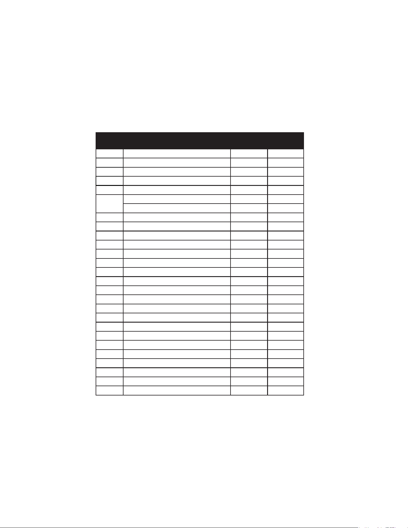
REPLACEMENT PARTS
ITEMITEM DESCRIPTION
SB2 QTY.
SB2PRO
QTY.
1 LID HANDLE 1 1
2 LID 1 1
3 GRATE 1 1
4 IGNITER 2 2
5 BURNER 2 2
6
LP ORIFICE 1.05mm 1
NG ORIFICE 1.6mm 1
7 BURNER BASE
8 BURNER PLATE 1 1
9 BODY 1 1
10 IGNITER WIRE 330mm 1 1
11 IGNITER WIRE 480mm 1 1
12 FLEX TUBE 200mm 1 1
13 FLEX TUBE 420mm 1 1
14 LED WIRE (SB2PRO Model Only) 1
15 LED LIGHT (WHITE) (SB2PRO Model Only) 2
16 BACK-LIT KNOB WIRE (SB2PRO Model Only) 1
17 FRONT PANEL (SB2PRO Model Only) 1 1
18 KNOB BEZEL 2 2
19 BACK-LIT PLATE (SB2PRO Model Only) 2
20 KNOB 2 2
21 LIGHT SWITCH (WHITE) (SB2PRO Model Only) 1
22 LIGHT WIRE (SB2PRO Model Only) 1
23 TRANSFORMER (SB2PRO Model Only) 1
24 VALVE 2 2
25 MANIFOLD 1 1
26 DRIP TRAY 1 1
17
SUMMERSET GRILLS
121324
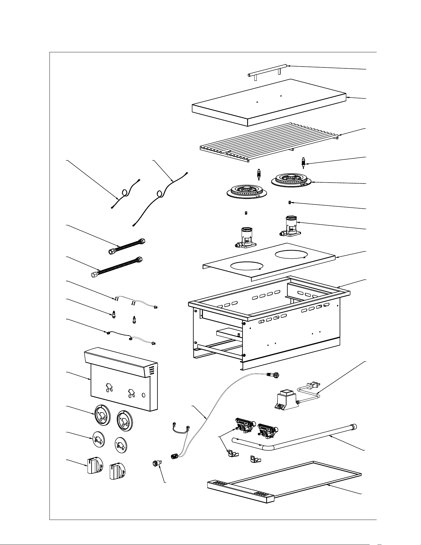
ILLUSTRATED PARTS
1
2
3
4
5
6
7
8
9
10 11
12
13
16
17
18
19
20
21
22
23
24
25
26
14
15
SB2PRO shown
18
SUMMERSET GRILLS
121324
Your investment in AMD Direct product is backed by the strongest
warranty in the industry. In addition to precision engineering and
outstanding performance, AMD Direct products include our GOLD
STANDARD LIFETIME
WARRANTY with all replacement parts 100% non-prorated. Effec-
tive with purchases 8/1/21.
AMD Direct Warranty is valid for original purchaser at original site
of delivery with proof of purchase and photo documentation only.
Registration form must be submitted online within 30 days of the
purchase date to validate the warranty. Warranty is void upon
transfer of ownership.
Warranty does not apply to products installed in any
commercial, rental, or nonresidential application (exception of the
Resort Side burner & TRL PRO). Warranty covers
replacement parts only. Manufacturer is not responsible for labor
or labor related costs. Warranty does not cover
discoloration, surface rust, corrosion, or oxidation, which may
occur due to harsh environments, chemicals, or overheating.
Warranty will not apply for damage resulting from improper instal-
lations, abuse, extreme environments, grease res, or misuse.
Proof of regular and proper
maintenance is required. Coastal, humid, and/or salt
environments are subject to manufacturer review. All out of box
claims must be made within 30 days of purchase and must be
made prior to installation. Any product installed damaged will be
considered damaged during installation and not covered under
warranty. Warranty and registration forms are available at
www.amddirect.com/register. Please be advised all display mod-
els are sold “as is” and the warranty covers the following items
only: main burners (Gold Standard Lifetime Warranty), grates
(Gold Standard Lifetime Warranty), burner covers (Gold Standard
Lifetime Warranty). All warranties are subject to the review and
approval of the manufacturer.
14520 DELTA LANE SUITE 105
HUNTINGTON BEACH, CA 92647
800.966.8126
AMDDIRECT.COM
COVERS
• Gold Standard Lifetime Warranty on covers, including side burn-
ers, carts, side/power burners & oven
COMMERCIAL APPLICATIONS
RESORT & TRLPRO Side burnerS
• Gold Standard Lifetime Warranty on workmanship, construc-
tion, & manufacturer defects for all commercial and/or hospitality
applications
• Warranty is void upon misuse, including lack of regular cleaning,
vandalism, or theft
• Warranty is valid only if regular maintenance is exercised. Due
to the nature of commercial applications (multiple users, lack of
control of use, etc.) regular maintenance is mandatory.
VENT HOODS, REFRIGERATION, COLD STORAGE & SINKS
VENT HOODS
• 5 Year Warranty on all Stainless Steel Construction
• 3 year Warranty on blowers, LED Lighting, wiring harness and
switches
15" & 24" REFRIGERATION MODELS
• 3 year Warranty on all construction including compressors
• 1 year Warranty on transformer, LED bulbs, LED harness, power
source wire, LED switches, interior halogen light wire/bulbs
22" REFRIGERATION MODELS
• 1 year Warranty on all construction & electrical components in-
cluding compressor, transformer, LED bulbs, LED harness, power
source wire, LED switches, interior halogen light wire/bulbs
COLD STORAGE & SINKS
• Gold Standard Lifetime Warranty on Ice Chests• Gold Standard
Lifetime Warranty on drains & faucets
DRAWERS, DOORS, Side burner LINERS, & CARTS
• Gold Standard Lifetime Warranty on construction, workmanship
and materials for all stainless steel parts, including doors, draw-
ers, side burner liners, & carts
• 3 year on electrical (Warming Drawers)
AMD DIRECT GAS APPLIANCES Side burn-
erS, SIDE/POWER BURNERS, & GAS OVEN
Gold Standard Lifetime Warranty on construction and manufactur-
er defects
• Gold Standard Lifetime Warranty on stainless steel construction
• Gold Standard Lifetime Warranty on cooking grates, burners,
burner covers, valves, ame tamers, and heat zone separators,
temperature gauges, & hood springs
• Gold Standard Lifetime Warranty on briquette systems
• 3 YEAR Warranty on all other parts, components, & electrical,
including: LED bulbs, wire harness, & switches; power source
wire; transformer; interior halogen light wire & bulb
WARRANTY

19
SUMMERSET GRILLS
121324
GAS PIPE SIZING CHART
REFERENCE
GAS PIPE SIZING
Length of Pipe in Feet
1/2” 3/4” 1” 1 - 1/4” 1 - 1/2” 2” 2 - 2 1/2” 3” 4”
10 275 567 1071 2205 3307 6221 10140 17990 35710
20 189 393 732 1496 2299 4331 7046 12510 25520
30 152 315 590 1212 1858 3465 5695 10110 20620
40 129 267 504 1039 1559 2992 4778 8481 17300
50 114 237 448 913 1417 2646 4343 7708 15730
60 103 217 409 834 1275 2394 3908 6936 14150
70 89 185 346 724 1086 2047 3329 5908 12050
80 78 162 307 630 976 1811 2991 5309 10830
90 69 146 275 567 866 1606 2654 4711 9613
100 63 132 252 511 787 1496 2412 4281 8736
125 54 112 209 439 665 1282 2083 3618 7382
150 48 100 185 390 590 1138 1808 3210 6549
175 43 90 168 353 534 1030 1637 2905 5927
200 40 83 155 325 491 947 1505 2671 5450
300 37 77 144 303 458 887 1404 2492 5084
NATURAL GAS : PIPE SIZING CHART
• Natural Gas (NG) flow is given in
thousands of BTU/hr. = 1 cubic
foot of NG gas - 1000 BTU
• Nominal pressure at the burner
for Natural Gas is 3.5” of water
column. (Typical machine supply
5”-7”)
• Pipe length must include
additional length for all fittings.
Add approximately 5 feet of pipe
per fitting.
• Natural Gas Example: A machine
with a burner that requires
440,000 BTU would need a 1 -1/4”
pipe for a 20” long run.
LIQUID PROPANE : PIPE SIZING CHART
NOTE: The sizing charts above list the specific pipe sizes required for the amount of BTU’s for a new gas line installations. If you
are using an existing gas line you must take into consideration the existing gas line capacities to ensure you will have proper
pressure. This chart is for reference only, we recommend you consult with a Licensed Plumber/Gas Fitter or NFPA54 (National Fuel
Gas Code - current edition) for more details.
Length of Pipe in Feet 1/2” 3/4” 1” 1 - 1/4” 1 - 1/2” 2” 2 - 2 1/2” 3” 4”
10 108 230 387 793 1237 2259 3640 6434 -
20 75 160 280 569 877 1610 2613 5236 9521
30 61 129 224 471 719 1335 2165 4107 7859
40 52 110 196 401 635 1143 1867 3258 6795
50 46 98 177 364 560 1041 1680 2936 6142
60 42 89 159 336 513 957 1559 2684 5647
70 38 82 149 317 476 896 1447 2492 5250
80 36 76 140 239 443 840 1353 2315 4900
90 33 71 133 275 420 793 1288 2203 4667
100 32 68 126 266 4 11 775 1246 2128 4518
125 28 60 117 243 369 700 1143 1904 4065
150 25 54 105 215 327 625 1008 1689 3645
175 23 50 93 196 303 583 993 1554 3370
200 22 47 84 182 280 541 877 1437 3160
300 17 37 70 145 224 439 686 1139 2539
• Liquid Propane (LP) Gas flow is
given in thousands of BTU/hr. =
1 cubic foot of LP gas - 2500 BTU.
• This chart refers to low pressure LP,
after regulation, Standard nominal
pressure at the burner for Liquid
Propane Gas is 11” of water column.
• Pipe length must include additional
length for all fittings. Add
approximately 5 feet of pipe per
fitting.
• LP Example: A machine with a
burner that requires 440,000 BTU
would need a 1” pipe for a 20’ long
run.
20
SUMMERSET GRILLS
121324
SIZE:
DESCRIPTION:
TOTAL CFM:
LIGHTING:
OUTER DIMENSIONS:
POWER:
NOISE LEVEL:
NOISE LEVEL:
DUCT SPECS:
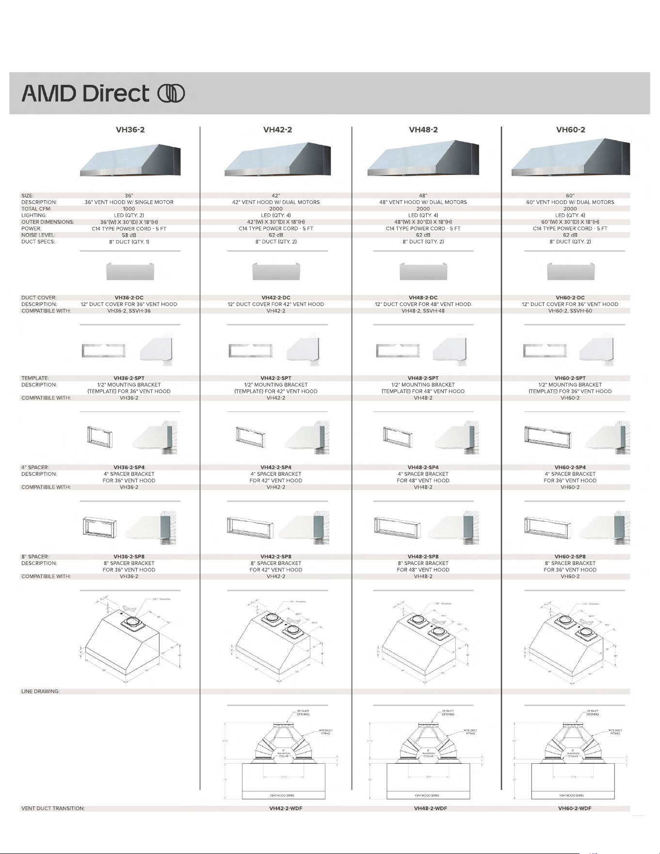
VH36-2 VH42-2 VH48-2 VH60-2
36”
36" VENT HOOD W/ SINGLE MOTOR
1000
LED (QTY. 2)
36”(W) X 30”(D) X 18”(H)
C14 TYPE POWER CORD - 5 FT
58 dB
58 dB
8” DUCT (QTY. 1)
DUCT COVER:
DESCRIPTION:
COMPATIBILE WITH:
VH36-2-DC
12" DUCT COVER FOR 36" VENT HOOD
VH36-2, SSVH-36
TEMPLATE:
DESCRIPTION:
COMPATIBILE WITH:
VH36-2-SPT
1/2" MOUNTING BRACKET
(TEMPLATE) FOR 36" VENT HOOD
VH36-2
4” SPACER:
DESCRIPTION:
COMPATIBILE WITH:
VH36-2-SP4
4" SPACER BRACKET
FOR 36" VENT HOOD
VH36-2
8” SPACER:
DESCRIPTION:
COMPATIBILE WITH:
LINE DRAWING:
VH36-2-SP8
8" SPACER BRACKET
FOR 36" VENT HOOD
VH36-2
42”
42" VENT HOOD W/ DUAL MOTORS
2000
LED (QTY. 4)
42”(W) X 30”(D) X 18”(H)
C14 TYPE POWER CORD - 5 FT
62 dB
62 dB
8” DUCT (QTY. 2)
VH42-2-DC
12" DUCT COVER FOR 42" VENT HOOD
VH42-2
VH42-2-SPT
1/2" MOUNTING BRACKET
(TEMPLATE) FOR 42" VENT HOOD
VH42-2
VH42-2-SP4
4" SPACER BRACKET
FOR 42" VENT HOOD
VH42-2
VH42-2-SP8
8" SPACER BRACKET
FOR 42" VENT HOOD
VH42-2
48”
48" VENT HOOD W/ DUAL MOTORS
2000
LED (QTY. 4)
48”(W) X 30”(D) X 18”(H)
C14 TYPE POWER CORD - 5 FT
62 dB
62 dB
8” DUCT (QTY. 2)
VH48-2-DC
12" DUCT COVER FOR 48" VENT HOOD
VH48-2, SSVH-48
VH48-2-SPT
1/2" MOUNTING BRACKET
(TEMPLATE) FOR 48" VENT HOOD
VH48-2
VH48-2-SP4
4" SPACER BRACKET
FOR 48" VENT HOOD
VH48-2
VH48-2-SP8
8" SPACER BRACKET
FOR 48" VENT HOOD
VH48-2
60”
60" VENT HOOD W/ DUAL MOTORS
2000
LED (QTY. 4)
60”(W) X 30”(D) X 18”(H)
C14 TYPE POWER CORD - 5 FT
62 dB
62 dB
8” DUCT (QTY. 2)
VH60-2-DC
12" DUCT COVER FOR 36" VENT HOOD
VH60-2, SSVH-60
VH60-2-SPT
1/2" MOUNTING BRACKET
(TEMPLATE) FOR 36" VENT HOOD
VH60-2
VH60-2-SP4
4" SPACER BRACKET
FOR 36" VENT HOOD
VH60-2
VH60-2-SP8
8" SPACER BRACKET
FOR 36" VENT HOOD
VH60-2
VENT DUCT TRANSITION:
24
VH42-2-WDF VH48-2-WDF VH60-2-WDF
30¼
18 ½ 21 ¾
24½
082724
VENT HOOD INFORMATION
21
SUMMERSET GRILLS
121324
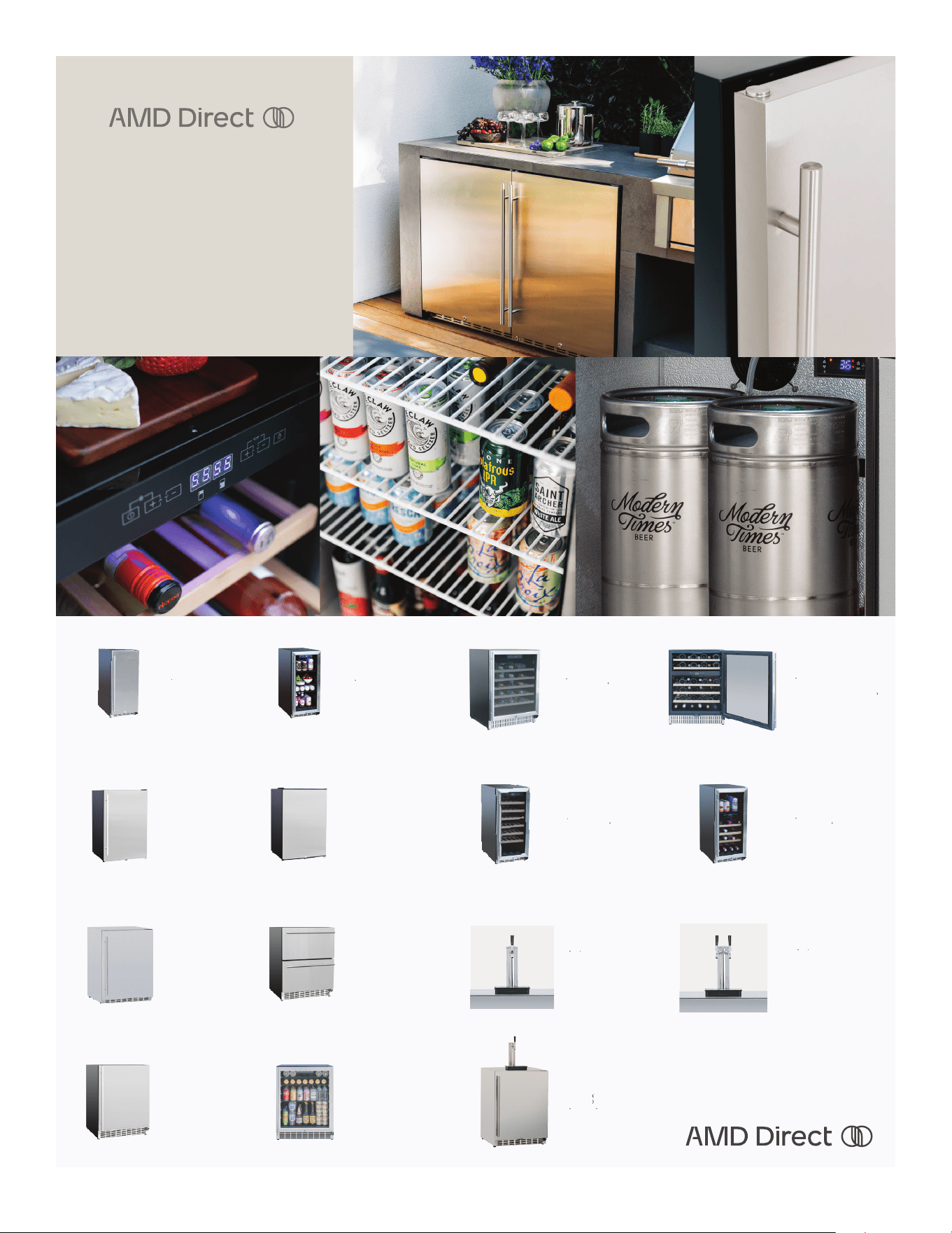
REFRIGERATION
AMD Direct oers a wide variety of luxury
Stainless Steel Refrigerators. With up to
5.3 cubic feet of storage, these appliances
will help keep your food fresh, wine chilled,
and beer cold, bringing the function of your
indoor refrigeration outside to join the party!
15” 3. 2C OUTD OOR RAT ED SINGL E
ZO N E W INE COOLE R
RFR
15 W
• Storage Capacity: 3.2 ft
• 28 Bottle Capacity
• 41° - 64° Temperature Rang e
15” 3. 2C OUTD OOR RA TED DU A L
ZONE W INE COOLE R
RFR
15WD
• Storage Capacit y: 3.2 ft
• 20 Bottle Capacity
• Upper Temperature Range: 41°-50°
• Lower Temperature Range: 50°-64°
24” 5. 3C DE LU XE OUTDOOR RATED
S INGLE Z O N E WINE COO LER
RFR 24W
• Storage Capacity: 5.3 ft
• 46 Bottle Capacity
• Temperature Range: 41°-64°
24” 5. 3C DEL U XE OU T DOOR
R AT ED DU A L Z ONE W INE COOLER
RFR
24WD
• Storage Capacit y: 5.3 ft
• 46 Bottle Capacity
• Upper Temperature Range: 41°-50°
• Lower Temperature Range: 50°-64°
RFR-22D / RFR-22D-R
• 156 Can Capacity
• Locking Door
• Right to Left Opening Model (RFR-22D-R)
• Upgraded Deluxe #304 Stainless Steel
Door & Handle
22” 4.1 Cu. DELUXE
COMPACT REFRIGERATOR
RF R- 22S
22” 4.1 Cu.
COMPACT REFRIGERATOR
• 156 Can Capacity
• #304 Stainless Steel Reversible Door
• Locking Door
15" 3.2C OUTDOOR RATED REFRIGERATOR
WITH GLASS DOOR
RFR
15 G
• Storage Capacity: 3.2 ft³
• 32° - 50° Temperature Range
• Black Interior
• Triple-Glazed S elf-Closing Glass Door w/ #304
Stainless Steel Frame & Handle
15" 3. 2C OU T DO OR RA TED
R E FRIGER ATO R
RFR 15S
• Storage Capacity: 3.2 ft³
• 32° - 50° Temperature Range
• Self-Closing #304 Stainless Steel
Door & Han dle
•
Storage Capacity: 5.3 ft
³
• 165 Can Capacity
• 32° - 50° Temperature Range
• Self-Closing #304 Stainless Steel Door,
Body & Handle
• Left & Right Doors Available
24” 5.3C DELUXE OUTDOOR
RATED REFRIGERATOR
RFR-24D / RFR-24D-R
24” 5 Cu. OUTDOOR RATED DOUBLE
DRAWER REFRIGERATOR
RFR-24DR2-A
• 114 Can Capacity
• Black Iterior Cabinet w/ Stainless Steel Drawer
• Soft-Closing Drawers
24" 5 CU. OUTDOOR RATED
REFRIGERATOR
RFR-24S-A / RFR-24S-AR
• 161 Can Capacity
• Glass Shelves (x3)
• Black Exterior & Interior Cabinet
• Right to Left Opening Door Model
(RFR-24S-AR)
• 161 Can Capacity
• Glass Shelves (x3)
• Black Exterior & Interior Cabinet
• Triple-Glazed, Tinted Glass Door
24" 5 CU. OUTDOOR RATED REFRIGERATOR
WITH GLASS DOOR
RFR-24G
24" 6. 6C DEL U XE OUTDOOR RA TED
K EGERAT OR
NO TAP / SINGLE TAP /
DOU B LE T A P
RFR 2 4DK / RFR 2 4DK1 / RFR
• Storage Capacity: 6.6 ft ³
• Available in Sin gle or Double Tap Towers
• 32° - 50° Temperature Range
• Self-Cl osing #304 Stainless Steel Door,
Body & Handle
• Left & Right Doors Available
SINGLE KEG TAP FOR KEGER ATO R
RFR TAP 1
• Fits RFR-24DK
• Inlcudes Tap Tray, Single Hose, CO2 Kit
(Tank & Regulator)
DOU B L E KEG TAP FO R KE G ER A TO R
•
Fits SSRFR-24DK
• Inlcudes Tap Tray, Two Hoses, CO2 Kit
(Tank & Regulator)
RFR TAP 2

22
SUMMERSET GRILLS
121324
CARE & CLEANING
INITIAL CLEANING AFTER INSTALLATION
• When rst installed, remove all protective plastic as
soon as possible.
• Clean the exterior stainless steel with stainless steel
cleaner (Bar Keeper’s Friend, Zep, or others) right after
installation.
• Clean the exterior regularly.
• Turn on the main bottom burners for 10 minutes to burn
off any production oils inside the side burner.
• Interior cleaning is suggested at a minimum of once
per season (using Simple Green) and an annual deep
interior cleaning.
EXTERIOR STAINLESS STEEL CLEANING
• Fill a bucket with warm water and soap (Dawn or Sim-
ple Green).
• Using a microber towel or sponge moistened with
soapy water, wipe down the surface of the side burner
following the grain of the metal as you clean.
• Rinse completely with clean water.
• Dry with a microber towel.
• Using Bar Keeper’s Friend, Zep, or other quality stain-
less steel cleaners helps to protect the porous stainless
steel surface from discoloration.
• Covering the side burner with a side burner cover when
not in use is a great way to protect the exterior.
REMOVE RUST LOOKING STAINS OR SPOTS
• Mix 1 tablespoon of baking soda in 2 cups of water.
• Rub the baking soda solution on the rust stain using
a toothbrush, being careful to go with the grain of the
stainless steel. If the stain is persistent, add vinegar,
little by little, to a cup of baking soda until you have a
consistent paste. Wipe the spot with paste and rinse
with a wet microber towel. Making certain you always
wipe in the direction of the grain of the stainless steel
• When stain is removed, wash entire surface with the
soap solution mentioned above. For grease build up,
use Zep on the exterior surface to remove.
MONTHLY INTERIOR CLEANING
• Turn the side burner on high for 15 minutes and close
the hood, similar to self-cleaning ovens, to burn up and
break down any interior buildup of grease and food
residue.
• Let the side burner cool down for roughly 90 minutes.
• Remove the cooking grates and soak them in a bucket
of warm water with Simple Green to remove baked-on
grime and grease.
• Remove the drip tray and scrape off any residue. Then,
spray with Simple Green and hose it off.
• Remove the briquette tray and brush off any residue.
• Wipe down the interior walls around the back burner
and side walls using a degreaser or stainless steel
cleaner for ovens and side burners.
• Remove the bottom burners. Lightly brush them off with
a stainless steel brush, and clean out the holes in the
burners, ensuring none are clogged.
• Turn and tap the burners with the main inlet hole down
to remove debris from inside.
• Use a stainless steel brush or putty knife to scrape
down the interior basin of the side burner.
• Using a shop vac, vacuum out the residue from the
bottom basin of the side burner.
• If desired, hose out the inside of the side burner and let
it dry before reinstalling the interior parts.
• After each use, burn off debris and brush clean.
RUST INFORMATION
Rust-like brown spots are formed when oxygen comes into
sustained contact with iron in a process called oxidation.
Oxygen is delivered to the metal from water, either from liq-
uid water or water vapor (rain or humidity). Carbon dioxide
in the air combines with the water to form a weak carbonic
acid, which breaks down into hydrogen and oxygen. This
process, along with some of the minerals and other parti-
cles in the air, can form rust-like deposits on the surface of
the porous stainless steel, resulting in brown spots. Another
cause is that free oxygen bonds with the dissolved minerals
and other particles in the air to form iron oxide, or rust-like
spots, in the pores.
Rust-like brown spot formations can also be encouraged
by architectural crevices, such as the polished welds and
edges of the metal surface, that can trap liquids. Once rust-
like brown spots form, the porous surface can trap addition-
al liquids, leading to further deposits on the stainless steel
surface.
Regularly cleaning the exterior surface with a stainless
steel cleaner, by spraying it on a clean microber towel or
cloth and wiping off the entire outside surface, can help
clean the pores. This regular cleaning should help keep
the stainless steel looking new, similar to waxing the paint
surface of a car.
The purchase and use of top-rated stainless steel cleaners
and polishers, along with stainless steel nish restoration
cleaners and renishers, may be necessary.

23
SUMMERSET GRILLS
121324
Page intentionally left blank

24
SUMMERSET GRILLS
121324
SUMMERSET GRILLS
For more information visit:
SUMMERSETGRILLS.COM
AMD Direct, Inc.
14520 DELTA LANE SUITE 105
HUNTINGTON BEACH, CA 92647
800.966.8126