SIZZLER PRO MANUAL

32 1/2"
25 5/8"
20"
20 1/2"
30 3/8"
7 7/8"
20 1/2"
37 1/2"
7 3/4"
25 1/2"
39 5/8"
20"
SIZPRO32
SIZPRO40
LINE DRAWINGS

Natural gas & liquid propane configuration
SIZZLER PRO INSTALLATION INSTRUCTIONS &
OWNER’S MANUAL
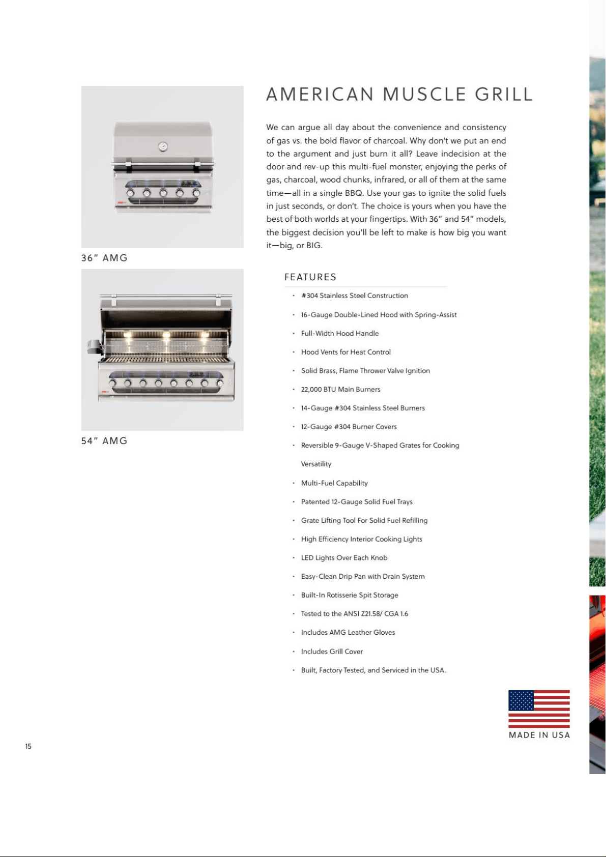
SIZZLER PRO 32”
SIZPRO32
SIZZLER PRO 40”
SIZPRO40
NAME:
PART #:
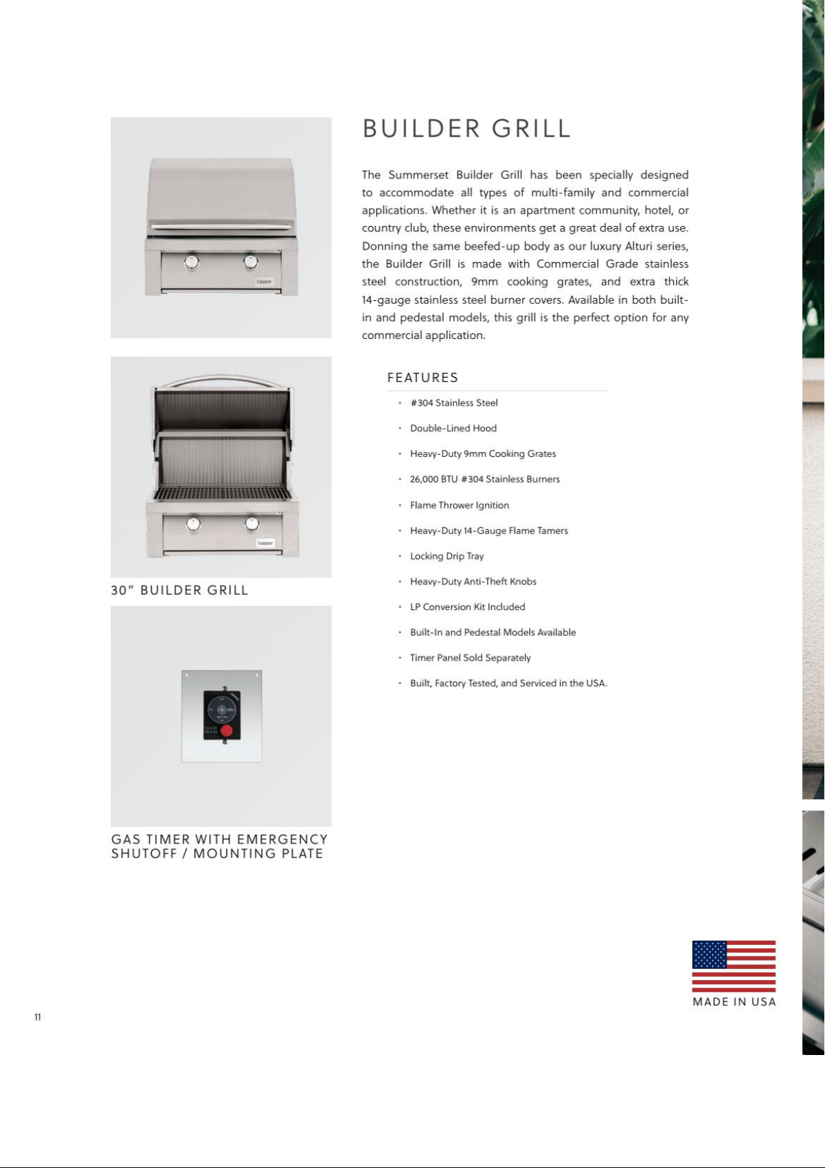
THANK YOU
INSTALLER:
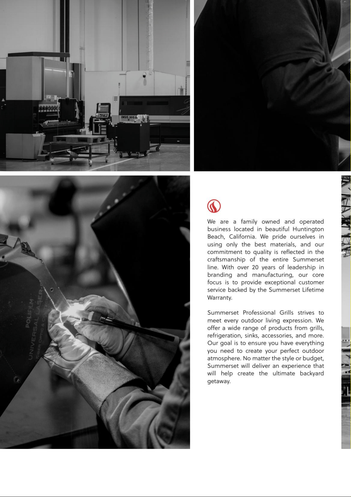
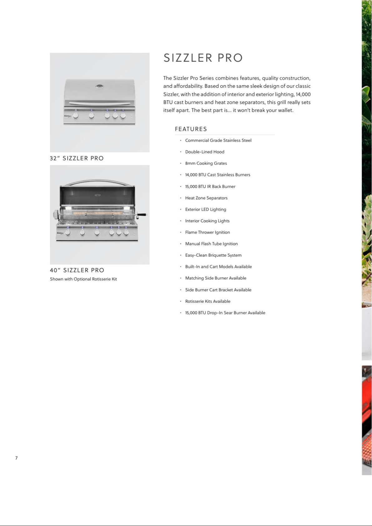
Thank you for your purchase. We’d like to welcome you to the Summerset family of luxury
outdoor kitchen products and look forward to being a part your home for years to come. As a
family business with over 30 years of industry experience, we aim to deliver exceptional quality
and personal service. Welcome to the Summerset family and we hope you love your new grill!
IMPORTANT FOR YOUR RECORDS
Please record the following information and refer to it when contacting Summerset Professional
Grills or an authorized dealer. The serial number is located on the rating plate. The rating plate
is located on the exterior basin of the grill ( re box) and on the underneath side of the drip tray
(select models only).
Serial Number:
Model:
Date of Purchase:
Place of Purchase:
Please leave this manual for the owner
To view on your phone, scan the QR code on your smart phone’s
camera app. (For Android devices, use Google Lens.)
For warranty information and to register your grill
visit, Summersetgrills.com/register/sizzlerpro
CALIFORNIA PROPOSITION 65
This product can expose you to chemicals
including Chromium which is known to
the State of California to cause cancer and
birth defects or other reproductive harm.
California law requires businesses to warn
customers of potential exposure to such
substances. To minimize exposure to
the substances, always operate this unit
according to the use and care instructions
found in this manual. Be certain to provide
adequate ventilation when cooking.
WARNING!
READ THIS MANUAL CAREFULLY AND
COMPLETELY BEFORE USING YOUR GRILL
TO REDUCE THE RISK OF:
Fire, Burn hazard, personal injury or
property damage. Improper installation or
servicing Electric Shock
WARNING!
CODE AND SUPPLY REQUIREMENTS:
This grill must be installed in accordance
with local codes and ordinances, or, in
the absence of local codes, with the latest
National Fuel Gas Code (ANSI Z223.1/
NFPA 54), or Natural Gas and Propane
Storage and Handling Installation Code
(CSA-B149.1)
WARNING!
• The outdoor cooking gas appliance
and its dedicated shutoff valve
must be disconnected from the
gas supply piping system during
pressure testing of that system at test
pressures in excess of .5 psi (3.5kPa).
• The outdoor cooking gas appliance
must be isolated from the gas supply
piping system by closing its dedicated
manual shutoff valve during any
pressure testing of the gas supply
piping system at test pressures equal
to or less than .5 psi (3.5kPa).
WARNING!
IF YOU SMELL GAS:
Improper installation, adjustment,
alteration, service or maintenance can
cause property damage, injury or death.
Read this manual thoroughly before
installation, use, or servicing of this
product.
DANGER!
IF YOU SMELL GAS:
Shut off ll gas supply lines to the grill
Extinguish any open ames
Carefully open the lid. Remember, it may
be extremely hot!
If odor continues, keep everyone away
from the grill and immediately call your
gas supplier or your re department
DANGER!
EXPLOSION HAZARD:
DO NOT use the grill as a storage area
for ammable materials. Keep area clear
and free from combustible materials,
gasoline, and other ammable vapors and
liquids. Failure to do so can result in death,
explosion, or re
An LP cylinder not connect for use shall not
be stored in the vicinity of this or any other
appliance
WARNING!
Improper installation, adjustment,
alteration, service or maintenance can
cause property damage, injury or death.
Read this manual thoroughly before
installation, use, or servicing of this
product.
THIS PRODUCT IS DESIGNED FOR
OUTDOOR USE ONLY
WARNING!
WARNING!
STATE OF MASSACHUSETTS
• Massachuse s requires all gas
be installed using a plumber or
gas er carrying the appropriate
Massachuse s license.
• All permanently-installed natural gas
or propane installations require a
"T" handle type manual gas valve be
installed in the gas supply line to this
appliance.
• This does not apply to portable
propane installations using a 20
pound cylinder.
SAFETY AND INSTALLATION WARNINGS
• Please read all instructions before installation or operating your gas grill to prevent injury
and appliance damage
• All gas grills will get hot during use. Use extreme caution when operating the grill
• Do not touch hot surfaces. Always use the handle to open or close the grill
• Never use dented, rusty or damaged propane cylinders. Never store additional or empty
propane cylinders in the grill cabinet or in the vicinity of this or any other appliance
• Close supervision is necessary when this or any appliance is used near children. Keep
children away from the grill during operation and until the grill has cooled o
• Children should never be left alone or una ended in an area where a grill is located. Place
your grill well away from areas where children play. Do not store items that may interest
children in or around the grill, in the cart, or in the masonry enclosure
• Never move the grill when hot. When in use, portions of the grill are hot enough to cause
severe burns.
• Always maintain the required clearances from combustibles as detailed. The grill is designed
for outdoor use only. Never use in a garage, building, shed, breezeway, or other enclosed
area. Do not use this grill under any unprotected overhead combustible construction
• Gas grills are not designed or certi ed for and are not to be installed in or on recreational
vehicles, portable trailers, boats or any other moving installation
• Always have an ABC Fire Extinguisher accessible — never a empt to extinguish a grease re
with water or other liquids.
• Storing your grill: Store your grill in a well-ventilated area. If stored indoors, detach and
leave L.P. cylinder outdoors in a well-ventilated area away from heat and away from where
children may tamper with it
• Keep any electrical supply cord and the fuel supply hose away from any heated surfaces.
Electrical cords should be placed away from walkways to avoid tripping hazard
• Do not repair or replace any part of the grill unless speci cally recommended in this manual.
Other service should be performed by a quali ed technician
• If the grill is installed by a professional installer or technician, be sure that he/she shows you
where your gas supply shut-off is located. All gas lines must have a shut-off that is readily
and easily accessible. If you smell gas, check for gas leaks immediately. Check only with a
soap and water solution. Never check for gas leaks with an open ame.
• Do not twist the gas supply hose
• Inspect the L.P. gas supply hose prior to each use of the grill. If there is evidence of excessive
abrasion or wear, or the hose is cut, it must be replaced before using the grill
• The use of accessories, regulators, or components not recommend by the appliance
manufacturer may cause injuries and will void warranty
• Never light the grill with the hood closed and be certain the burners are positioned and
seated over the gas valves and on the burner support
• Never lean over the cooking surface when lighting or operating the grill
• Use barbecue tools with wood handles and insulated oven mi s when operating the grill
• Be sure the gas supplied to the grill conforms to the model you purchased. A natural gas grill
requires natural gas to operate; a liquid propane grill requires liquid propane to operate
• Never connect the appliance to an unregulated gas supply line. Grills operated without
a regulator are unsafe and will not be serviced until installed properly and safely. Unsafe
operation without a gas regulator will void the warranty
• Grills operating with natural gas must be installed with the NG regulator supplied with the
unit and set to 4.0” of water column pressure
• Grills operating with liquid propane must be installed with an LP regulator and set to 11” of
water column pressure
WARNING!
6
TABLE OF CONTENTS
Replacement Parts List
Exploded View
Before Grilling
Installation
Gas Requirements
Lighting The Grill
Maintenance Tips
Grill Features
Warranty
1
1
2
3
5
8
8
10
12
SIZPRO32 SIZPRO40
HOOD-SIZ32
32"-TOP HOOD 1
HOOD-SIZ40
40"-TOP HOOD 1
2
BACK BURNER ACCESS DOOR
1 1
REAR HOOD-SIZ32
32"-REAR HOOD 1
REAR HOOD-SIZ40
40"-REAR HOOD 1
WARM-SIZ32
32"-WARMING RACK 1
40"-WARMING RACK 1
5
GRATE-SIZ
TOP GRATE 4 5
6
BRNCOV-SIZ
BRIQUETTE TRAY 4 5
7
HEAT SEP-SIZPRO
HEAT SEPARATOR 3 4
8
CROSS-SIZ
CROSS FIRE TUBE 3 4
9
CAST-SIZ
CAST BURNER 4 5
10
HEAT SHIELD-SIZ
HEAT SHIELD 4 5
BASIN-SIZ32
32"-BASIN 1
BASIN-SIZ40
40"-BASIN 1
DRIP-SIZ32
32"-DRIP TRAY 1
DRIP-SIZ40
40"-DRIP TRAY 1
13
TRANS-SIZ
TRANSFORMER 1 1
14
REG-SIZ-NG
NG REGULATOR
1 1
15
REG HOSE LP
LP REGULATOR WITH HOSE
1 1
16
N/A
INLET FITTING(LP MODEL ONLY) 1 1
MAN-SIZ32
32"-MANIFOLD 1
MAN-SIZ40
40"-MANIFOLD 1
18
MV LATCH
VALVE LATCH 5 6
19
MV-SIZ
MAIN VALVE 4 5
20
BBV-SIZ
IR BURNER VALVE 1 1
21
FLEX TUBE-BB-SIZ
IR BURNER FLEX TUBE 1 1
22
KNOB SIZPRO
KNOB-MAIN BURNER 4 5
23
KNOB SIZPRO-RB
KNOB-BACK BURNER 1 1
24
LIGHT HARN-SIZPRO LIGHT WIRING
1 1
25
SWTCH-SIZPRO
LIGHT/LED SWITCH 2 2
26
KNOB BZL SIZPRO
KNOB BEZEL-MAIN BURNER 4 5
27
KNOB BZL SIZPRO
KNOB BEZEL-BACK BURNER 1 1
28
LOGO PLATE - SIZ
LOGO PLATE 1 1
FRONT-SIZ32
32"-CONTROL PANEL 1
FRONT-SIZ40
40"-CONTROL PANEL 1
30
N/A
FIXING PLATE-LED LIGHT 5 6
31
LED BULB-SIZPRO
LED LIGHT 5 6
LED WIRE-SIZPRO32
32"LED WIRING 1
LED WIRE-SIZ40
40"LED WIRING 1
N/A
COVER PLATE-32"LED WIRING 1
N/A
COVER PLATE-40"LED WIRING 1
34
ROT HAND
ROTISSERIE HANDLE (OPTIONAL) 1 1
35
ROT WEIGHT
BALANCE WEIGHT(OPTIONAL) 1 1
36
ROT COLLAR
SPIT COLLAR (OPTINAL) 1 1
SPIT-SIZ32
32"ROTISSERIE SPIT (OPTIONAL) 1
SPIT-SIZ40
40"ROTISSERIE SPIT (OPTIONAL) 1
38
ROT FORKS
SKEWER FORK (OPTIONAL) 1 1
39
N/A
THUMB SCREW (OPTIONAL) 3 3
40
ROT MOT BRAK-SIZ
MOTOR BRACKET (OPTIONAL) 1 1
41
ROT MOT
ROTIESSERIE MOTOR (OPTIONAL) 1 1
42
BBEW-SIZ
IR BURNER IGNITION WIRE 1 1
43
BBE-SIZ
IR BURNER IGNITION 1 1
44
BBE-COV-SIZ
IR BURNER IGNITION HOUSE 1 1
45
ROT FIT-SIZ
IR BURNER ELBOW FITTING 1 1
46
ROT NUT-SIZ
IR BURNER JOINT NUT 1 1
47
BBO-SIZ
IR BURNER ORIFICE 1 1
48
IR-BACKBRN-SS
IR BURNER 1 1
49
LIGHT SIZPRO-R
INNER LIGHT- RIGHT SIDE 1 1
LIGHT SIZPRO-L INNER LIGHT- LEFT SIDE
1
1
HOODHAND-SIZ32
32"-HOOD HANDLE
1
HOODHAND-SIZ40
40"-HOOD HANDLE 1
52
HOODBUMP-SS
RUBBER STOPPER 2 2
53
TEMP BZL-SSR
TEMP GAUGE BEZEL 1 1
54
TEMP-SSR
TEMP GAUGE 1 1
55
N/A
COVER PLATE-TEMP GAUGE 1 1
29
ITEM PART NO. DESCRIPTION
QT
Y.
1
3
4
11
12
17
32
33
37
50
51
PARTS LIST
WARM-SIZ40
BBAD-SIZ
SIZPRO 32- EXPLODED VIEW
SIZPRO 40- EXPLODED VIEW
2
BEFORE GRILLING
SHIPMENT ARRIVING DAMAGED:
IMPORTANT NOTES:
VISIBLE DAMAGE
If your shipment arrives with visible damage to
the box/carton, be sure the damage is noted
on the bill of freight or express receipt and
signed by the person making the delivery. File
claim for damages immediately, regardless of
the extent of damage.
BE MINDFUL OF WIND DIRECTION
When selecting a suitable location, consider
important factors such as exposure to the
wind and foot tra c pa erns. If you have a
freestanding grill, position it so the prevailing
wind blows into the front control panel (at
your back when grilling), allowing for proper
front to rear air ow. Built-in grill located
in areas with prevailing winds should be
protected by a wind barrier, wind de ector, or
wind guard. The grill is designed to pull in air
from the front and exhaust through the rear
of the unit. Winds hi ing the back of the grill
directly may cause problems. Be sure wind
doesn’t blow into the hood gap.
CONCEALED DAMAGES
If damages are unnoticed until the grill is
unpacked, notify the transportation company
or carrier immediately and fil a concealed
damage claim with them. This should be done
within (5) days of the delivery date. Be sure to
hold on to the box/carton for inspection. We
cannot assume responsibility for damage or
loss incurred in transit.
GAS LINE LENGTH
Keep all gas supply lines as short as possible.
Gas lines lose pressure over distance and with
each elbow or “t” ing added. This drop in
pressure a ects grill performance.
PROPER LEVELING
PROPER LEVELING DURING INSTALLATION
IS CRITICAL. A GRILL THAT IS OUT OF LEVEL
WILL CAUSE ERRATIC BURNER COMBUSTION
AND INEFFICIENT, UNEVEN HEATING. THE
GRILL SHOULD BE LEVEL IN ALL DIRECTIONS.
ADJUSTMENTS MAY NEED TO BE MADE EACH
TIME WHEN MOVING A FREESTANDING UNIT.
CONSTRUCTION ZONES
Keep all stainless steel products away from
construction zones. Construction debris such
as (but not limited to) stone dust, stucco,
and lime dust could damage or permanently
discolor stainless steel products. Keep all
caustic chemicals including chlorine and pool
cleaning products away from stainless steel at
all times.
TESTING FOR LEAKS
Create a soapy water solution of 1 part soap
and 3 parts water. Con rm that all control
knobs are in the off position. Turn on the
fuel supply. For natural gas, turn the valve
handle ¼ turn to align with the gas ow. For
LP, turn the cylinder valve counter clockwise
one full rotation. Apply the soap solution
generously by paint brush or squirt bo le on
all connections and ings. If bubble appear
to grow on any of the connections, you have
a gas leak. IMMEDIATELY turn off the gas
supply. Wash off the soapy solution with
cold water and dry. Tighten the loose joint
or replace the faulty part with manufacturer-
recommended replacement parts. DO NOT
a empt to repair the L.P. cylinder valve if it
is damaged. The only way to safely resolve a
damaged cylinder is to replace it by calling an
authorized gas appliance service technician
or an LP gas dealer. Repeat the leak test to
ensure that no leaks are present. Do not use
the appliance until the leak is corrected.
3
Grill Model A: Width
B: Height
C: Depth
Sizzler Pro 32” 30 5/8
20 3/4
8
Sizzler Pro 40”
20 3/4
8
Grill Model
A: Width B: Height C: Depth
Height-Hood Open
Sizzler 32" 32 1/2 25 1/220 30
Sizzler 40" 39 1/2 25 1/220 30
CUT OUT DIMENSIONS
OVERALL PRODUCT DIMENSIONS
INSTALLATION
IMPORTANT NOTES:
Clearance between grill and strictly non-
combustible wall (i.e. brick wall, Clearance
Fig. 1). The grill must have a minimum of 4”
right, left and rear clearance from any non-
combustible wall. This allows for proper
ventilation and helps prevent dangerous
overheating.
ALL BBQ ISLANDS MUST BE MANUFACTURED
FROM “NON COMBUSTIBLE” MATERIAL. IF
COMBUSTIBLE MATERIAL IS BEING USED, A
SUMMERSET GRILL LINER IS REQUIRED.
NOTE:
For the minimum clearances between
the grill and any side or rear walls, your
setup must fall within one (or more) of the
following:
Clearance between grill and protected
combustible wall (i.e. a non-combustible
wall in front of a combustible wall to serve as
a barrier. This can be accomplished by brick or
a metal stud nished with non-combustible
substrate. Clearance Fig. 2). The grill must
have a minimum of 14” right, left and rear
clearance from the protected combustible
wall. (The 4” non-combustible material
clearance, plus an additional 10” clearance
between the grill and protected wall.)
A
B
C
A
37 3/4
4
INSTALLATION
EXHAUST HOOD REQUIREMENTS
When using an exhaust hood, the area
above the cooking surface of the grill
must be covered with a hood larger than
the cooking area of the grill, AND with
a minimum of 1200 CFM (cubic feet per
minute) for proper outdoor application
SIDE AND R
EAR WALL CLEARANCES
Clearance between grill and combustible
wall (Clearance Fig. 3). The grill must have a
minimum of 18” right, left and rear clearance
from any combustible wall.
BACK SPLASH CLEARANCE
(
IF APPLICABLE
)
If a non-combustible backsplash exists, it
must have a minimum of a 4” clearance
from the rear of the grill (to allow for proper
ventilation and help prevent dangerous
overheating. Clearance Fig. 4).
IMPORTANT NOTES:
This 4” backsplash clearance must rst be met
prior to any non-combustible walls beginning
behind it.
CLEARANCE TO OVERHEAD
CONSTRUCTION AND EXHAUST
HOOD REQUIREMENTS
• DO NOT use this appliance under
unprotected combustible overhead
construction without an exhaust
hood.
• When installed under overhead non-
combustible construction, an exhaust
hood is highly recommended.
CHECK LOCAL CODES
This grill is designed for outdoor use only. DO
NOT use this grill inside a building, garage, or
enclosed area. DO NOT use this grill in or on a
recreational vehicle or boat.
When
installing this grill in a combustible
surround, a Summerset insulating jacket/grill
liner must be used.
A minimum ve (5) foot clearance is required
between the counter-top and the
overhead combustible or non-combustible
construction.
When installed under combustible
overhead construction, the area above
the cooking surface of the grill must be
covered with an exhaust hood. The exhaust
hood provides the protection for the
combustible overhead construction.
IMPORTANT NOTES:
5
INSTALLATION / GAS REQUIREMENTS
Combustible Overhead Construction:
Exhaust hood required.
Non-Combustible Overhead
Construction: Exhaust hood is highly
recommended.
CHECK LOCAL BUILDING CODES
UNPACKING YOUR GRILL
Included with your Sizzler Pro grill are the
following loose items:
Cooking Grates: SIZPR032(4), SIZPR040(5) Burner
Covers: SIZPR032(4), SIZPR040(5)
Warming Rack: SIZPR032(1), SIZPR040(1)
Drip Tray: SIZPR032(1), SIZPR040(1)
Heat Zone Separators: SIZPR032(3), SIZPR03(4)
Conversion Kit:
• Set of ori ces
• If grill is factory set LP, NG ori ces will
be included
• If grill is factory set NG, LP ori ces will
be included
• The drip tray will be at the bo om of
the unit and will slide into the drip tray
support brackets.
• Above the heat shields are the Red
Brass Burners (already installed).
GAS REQUIREMENTS
NATURAL GAS AND LIQUID PROPANE
REQUIREMENTS
When using an exhaust hood, the area above
the cooking surface of the grill must be
covered with a hood larger than the cooking
area of the grill, AND with a minimum of
1200 CFM (cubic feet per minute) for proper
outdoor application
WARNING!
GAS LINES
Never connect a gas line directly to the
grill. A pressure regulator must be installed
on all gas equipment. Removing or failing
to install the pressure regulator can result
in re and serious personal injury and will
void the warranty
MINIMUM PRESSURE REQUIREMENTS
Ensure the gas supplied meets the minimum
pressure requirements. See below table for
gas requirements measure in water column
(w.c.) pressure:
Gas Type Maximum Minimum
Natural Gas 7” w.c. 4” w.c.
Liquid Propane 14” w.c. 11” w.c.
The burner covers or brique e trays are
above the burners and a ach to the
mounting pegs located inside the rebox.
The cooking grates are placed above the
burner covers and nally the warming rack
is placed on the mounting tabs
Both the regulator and burner ori ces have
been tuned for the type of gas speci ed on
the rating plate. Converting to a di erent
type of gas requires a conversion kit.
Conversion kits are included with this grill
and located with the manual. Converting
gases may require additional parts not
included with this grill. (See Gas Conversion
section for details).
6
GAS REQUIREMENTS
NOTE: DO NOT use any tape, pipe dope or
threading compound on any are ing. This
will cause a clog in the regulator and prevent
your grill from functioning properly.
LIQUID PROPANE TANK REQUIREMENTS
NATURAL GAS REQUIREMENTS
CONNECTING TO THE NG REGULATOR
Turn off the gas at the supply when grill is not
in use.
Please ensure:
• Summerset Professional Grills
recommends that only quali ed
professionals perform the required
plumbing on this product.
• Check the Rating Plate to make sure the
gas supply you are hooking up to is the
gas type the grill is manufactured for.
• To ensure satisfactory performance,
the gas supply line must be sized
to accommodate the total BTU
requirements of all the gas- red
equipment that will be connected to
that line.
• In no case should pipe less than 1/2”
inside diameter or 1” outside diameter
ever be used to connect this product.
• The LP gas tank has a shutoff valve,
terminating in an LP gas supply tank
valve outlet that is compatible with a
Type 1 tank connection device. The LP
gas tank must also have a safety relief
device that has a direct communication
with the vapor space of the tank.
• The tank supply system must be
arranged for vapor withdrawal.
• The LP gas tank used must have a collar
to protect the tank valve.
CONNECTING TO THE LP TANK
Never connect an unregulated LP gas tank
to your gas grill. The gas regulator assembly
supplied with your gas grill is adjusted to have
an outlet pressure of an estimated 11” water
column (W.C.) for connection to an LP gas tank.
The hose and regulator are connected in the
following manner:
• Use a standard 20 lbs. LP tank with QCC
– 1 ing
• Grills set up for LP gas come equipped
with an LP hose regulator assembly
for connection to a standard 20 lbs. LP
cylinder (Type 1)
• Insert the regulator inlet into the
cylinder valve and turn the black
coupling nut clockwise until the
coupling nut is hand tight. DO NOT
over-tighten this connection.
• To disconnect the coupling nut, rst
make sure the main cylinder valve is
turned o . Grasp the coupling nut and
turn counter clockwise. The inlet will
then disengage.
IMPORTANT:
All installation and all installation parts
must conform to local codes with the
National Electrical Code, ANSI Z223.1/
NFPA 70 latest edition and the National
Fuel Gas Code ANSI Z223.1/NFPA 54 in
the U.S. and CGA-B149.1/.2 in Canada
7
GAS REQUIREMENTS
FILLING AND REFILLING LP GAS CYLINDERS
All purging and re lling of LP gas cylinders
must be performed by quali ed personnel in
the LP gas industry. Never store a spare LP gas
cylinder under or near this appliance.
Never ll the LP gas cylinder beyond 80 percent
full. Failure to follow these instructions may
result in explosion, personal injury or death.
LP gas grill models are designed for use with
a standard 20 lb. liquid propane gas (LP) tank
with type (1) valve connections. (Not included)
Never connect your gas grill to an LP tank that
exceeds this capacity. A tank of approximately 12
inches in diameter by 18-1/2 inches high is the
maximum size LP gas tank to use. A propane
tank with an OPD (Over ll Prevention Device)
must be used. This safety feature prevents the
tank from being over- lled which can cause
malfunction of the LP gas tank, regulator and/
or grill.
The LP cylinder must be constructed and
marked in accordance with the speci cations
for LP gas cylinders of the U.S. Department
of Transportation (DOT) and designed for use
with a Type 1 system only. Be sure to read and
follow all LP connection instructions.
A dented or rusty LP cylinder may be
hazardous and should be avoided. If in
doubt, have it checked by your LP supplier.
Always check for leaks a er every LP cylinder
change. (See Checking For Leaks)
Cylinders must be stored outdoors in a well-
ventilated area out of the reach of children.
If your grill is stored indoors, the LP cylinder
must be stored outside, in upright position
and away from excessive heat.
CONNECTING TO A SIDE BURNER
You will need a ‘T’ adapter ing (not
provided) or similar connection to connect
a single gas line to both a side burner and
a grill. We recommend a licensed gas
technician install all gas lines. See below
gure for installation of a ‘T’ adapter.
IMPORTANT
All installation and all installation parts
must conform to local codes with the
National Electrical Code, ANSI Z223.1/
NFPA 70 latest edition and the National
Fuel Gas Code ANSI Z223.1/NFPA 54 in the
U.S. and CGA-B149.1/.2 in Canada
LIQUID PROPANE INSTALLATION
NOTE: Ventilation is require in the enclosure
on opposite sides to create cross-ventilation.
Liquid propane is heavier than natural gas
and vents should be located near the bo om
of the enclosure.
Before lighting the burners, inspect the
gas supply piping or hose. If there is
evidence of cuts, wear, or abrasion, it must
be replaced prior to use. Always keep your
face and body as far away from the grill as
possible when lighting.
WARNING!
8
LIGHTING THE GRILL / MAINTENANCE TIPS
VALVE IGNITION
MANUAL IGNITION
BEFORE LIGHTING ROTISSERIE BURNER
NOTE:
CAUTION: Always wait ve (5) minutes for
gas to clear a er any unsuccessful lighting
a empt.
IMPORTANT: REMOVE THE WARMING
RACK PRIOR TO TURNING ON THE
ROTISSERIE BURNER. Turning the rotisserie
burner on while the warming rack is installed
will cause the warming rack to warp and void
the warranty.
NOTE: Keep the hood closed during the pre-
heat period.
Never operate the grill una ended. DO
NOT OPERATE ROTISSERIE BURNER WITH
WARMING RACK INSTALLED
1. Follow steps 1-3
2. Place either a burning long-barrel butane
lighter or a burning long-stem match near
the manual ash tube to the right of the
grill. For back burners, hold the ame
against the surface of the back burner.
3. Hold the lighter or match ame at the
top of the manual ash tube for ve (5)
seconds, or, next to the back burner. Then
depress the appropriate control knob and
while pressing turn it counterclockwise
• Open the hood before lighting; do not
a empt to ignite burners while hood is
closed.
• Make sure gas supply is turned on.
• Make sure burner control knobs are in
the “OFF” position.
• Press in the control knob then slightly
turn the knob counterclockwise while
still pressing in.
• Hold in the above position for 5 seconds
allowing the gas to reach the manifold.
• Turn the knob counterclockwise past the
ignition to the high se ing to ignite. You
will hear the one time clicking sound of
the spark ignition.
• A er ignition, set the knob to the desired
se ing.
Your Summerset Professional Grill is
equipped with reliable, high-e ciency
piezo ignition valves. Below are instructions
for valve ignition and manual ignition
lighting.
PLEASE Keep your face and body away from
the grill top when lighting
1. If the burner doesn’t ignite, wait ve (5)
minutes before repeating steps 4-7.
2. DO NOT turn on more than one valve
at a time for either
MAINTENANCE TIPS
PRE-HEATING THE GRILL
Pre-heating your grill every time you use it
is extremely important. Pre-heating allows
the brique es to properly heat up, providing
more even and more consistent cooking
results. Pre-heat your grill by igniting all main
burners. Then close the hood and allow the
grill to heat for 10 to 15 minutes, the hood
thermometer should reach approximately
450°. Once you’ve reached your desired
pre-heat temperature, turn off the burners
that you won’t be using to cook your food.
Remember, surface temperature can be up to
200° higher.
SHUT OFF INSTRUCTIONS
1. To shut off the unit, depress each valve
control knob and while pressing turn
clockwise to the “OFF” position.
2. Always close the valve from the gas
supply a er each use of the unit.
NOTE: When using a portable propane tank:
Propane tanks are equipped with a safety
shutdown device that may cause low or no gas
pressure/ ame at the burners if operating and
lighting instructions are not followed exactly.
to the HI position. Remove the lighter or
match when the burner lights and release
the control knob.
4. If the burner does not light within ve
(5) seconds of turning the control knob,
immediately depress the knob and turn
the control knob to o . Wait ve (5) minutes
before repeating steps 2-4 of the MANUAL
LIGHTING instructions.
IMPORTANT
9
MAINTENANCE TIPS
CLEANING THE DRIP TRAY
The drip tray should be cleaned a er each use.
A er the grill is completely cool, remove the drip
tray by pulling it out until it stops, then li ing
the front edge until the drip tray comes free.
Clean it with hot soapy water or an oven-style
cleaning product and re-install. When using an
oven-style cleaning product be sure to carefully
LOW FLAME ADJUSTMENT
MAINTENANCE TIPS
Routinely wash with warm soapy water and
apply stainless steel polish to protect grill
exterior
STAINLESS STEEL NEEDS TO BE CLEANED?!?
ABSOLUTELY!
Stainless steels need to be cleaned for aesthetic
considerations and to preserve corrosion
resistance. Stainless steel is protected from
corrosion by a thin layer of chromium oxide.
Oxygen from the atmosphere combines with
the chromium in the stainless steel to form
this passive chromium oxide lm that protects
from further corrosion. Any contamination of
the surface by dirt, or other material, hinders
this passivation process and traps corrosive
agents reducing corrosion protection. Thus,
routine cleaning is necessary to preserve the
appearance and integrity of the surface.
• To Adjust the Burner to a Low Se ing:
• Make sure the grill is cool
• Remove the racks so you can see the
ames while adjusting the burners
• Light the burner and allow it to preheat
on high for 3 minutes
• Turn the burner to “LOW”
• Pull off he control knob
• Use a at head screw driver and adjust
the “gold athead screw” in the valve
to the proper ame height
GRILL EXTERIOR
STAINLESS STEEL MAINTENANCE
When removing stubborn stains:
• Do not use metallic abrasives and
always rub in the direction of the grain
• Some household cleaning products
are not suitable for stainless steel; be
sure to read the label before using on
the grill
• Always use the mildest cleaning
solution rst, scrubbing in the direction
of the grain
• Specks of grease may gather in the
grain of the stainless steel and bake on
to the surface, giving the appearance
of rust
• To remove these baked-on foods use
a ne to medium grit non-metallic
abrasive pad (Scotch Brite is good)
in conjunction with a stainless-steel
cleaner
• Solutions used for cleaning concrete
and masonry can be very corrosive and
will ‘a ack’ stainless steel
• Be sure your Summerset products
are well protected before using these
products
A er each use wipe down the exterior of the
grill to remove grease and spla ers. Use a
commercially available stainless steel cleaner
to clean and polish the exterior surfaces.
Doing these things on a regular basis
minimizes the amount of e ort required
• Burn off excess food debris and
marinades for 15 minutes a er cooking
• Once the unit is cool, turn over the
burner covers and burn the top side
(the burner covers are reversible and
are able to be mounted upside down
for cleaning purposes)
• Use an approved stainless-steel oven
cleaner to remove grease build up
• Routinely have a professional barbecue
cleaning company detail the barbecue
for best results and longevity
GRILL INTERIOR
follow the manufacturer’s instructions. Many of
these cleaners are toxic and can damage the
stainless-steel nish if not used properly. Also,
check the tray a er rain. If you’ve left the grill
uncovered, you may need to remove the drip
tray to drain the water from the tray.
10
GRILL FEATURES
A er your rst use, certain areas of the grill
may discolor from the intense heat given o
by the burners - this is normal and cannot
be cleaned o . For light and heavy food
stains there are many di erent stainless-steel
cleaners available.
ROTISSERIE INSTALLATION
CAUTION: When using the back burner,
keep the grill lid closed to prevent heat loss,
provide proper convection and provide
proper venting. This will ensure even cooking
temperatures.
1. Remove the warming rack, cooking
grates, and cooking grates if necessary
2. Mount the rotisserie motor bracket on
either side of the grill nearest the outlet
3. Slide the rotisserie motor onto the
rotisserie motor bracket
4. Insert rotisserie spit (rotisserie rod) into
motor
5. Place 1st fork onto the rotisserie spit and
secure tightly
When using the rotisserie with the hood open,
be careful in windy conditions, always being
mindful of heat dispersion.
Do not use the rotisserie motor in the rain. Do
not leave the motor on the grill when not in
use.
IMPORTANT: Turn the back burner to low or
off when stopping the rotisserie to prevent
over cooking
HEAT-ZONE SEPARATOR INSTALLATION
To install the heat zone separators, please
insert the heat zone separators as shown in
the gure below.
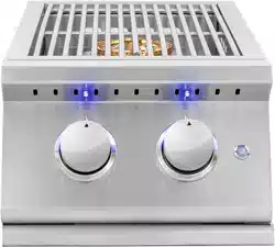
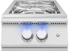
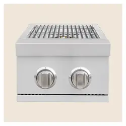
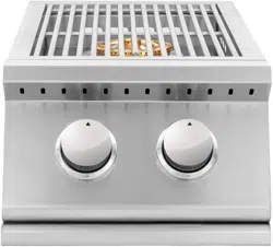
OPTIONAL DROP-IN SEAR BURNER
INSTALLATION
The preferred location to install a drop-in sear
burner is on the far left of the grill. This will
allow for a sear zone while maximizing the
main burner grilling space. To install a drop-in
sear burner:
• Remove the grate and burner covers to
access the main burner
• Remove the co er pin securing the
main burner (if necessary)
• Remove main burner
• Remove cross tube in between main
burners allowing for drop-in sear
burner to rest at, if necessary
• Install sear burner with the center of
the ori ce positioned in the center of
the burner and rest the back of sear
burner at on the rear of the grill. There
is a locating pin in the rear of the sear
burner that must be seated correctly.
IMPORTANT NOTE: FOR LOCATIONS
NEAR COASTAL AREAS AND POOLS
#304 stainless steel materials used in the
construction of your Summerset Professional
Grill are highly rust resistant, however,
chlorine in the air from swimming pools or
the salt from sea air may cause surface rust to
appear and even create some pi ing if left on
the product. Here are a few tips to avoid this:
• Regularly wipe down the exterior
surfaces with a damp cloth (micro ber
towels work well)
• Allow the surfaces to dry before
installing the cover Do not cover a
damp grill
• In extreme environments apply a rust
inhibitor which leaves a microscopic
protective layer on the grill
• For seasonal storage use the product
referred to above, ensure the grill is
dry, then cover and secure the cover
to minimize the amount of damp air
ge ing to the surfaces
6. Position the meat onto the spit securing
to the 1st fork
7. Place 2nd fork onto the spit securing to
the meat and tighten screw
8. Insert collar onto spit
9. Screw on handle nut and handle
10. 1Add a drip pan beneath the meat to
catch drippings and retain moisture in
the meat
11. Light back burner per lighting
instructions in this manual and close
grill lid
GRILL FEATURES
LIGHTING DROP-IN OPTIONAL SEAR
BURNER
1. Open the hood before lighting; do not
attempt to ignite burners while hood
is closed.
2. Make sure gas supply is turned on.
3. Make sure burner control knobs are in
the “OFF” position.
4. Press in the control knob then slightly
turn the knob counterclockwise while
still pressing in.
5. Hold in the above
position for 5 seconds
allowing the gas to reach the manifold.
6. Turn the knob counterclockwise past
the ignition to the high se ing to
ignite. You will hear the one time
clicking sound of the spark ignition.
7. After ignition, set the knob to the
desired setting.
8. Using the main burner sear burner zone
improperly can cause extreme damage.
100% attendance to this style of cooking
is required.
11
POWERING FRONT PANEL LED
To power internal halogen and external LED
lights, insert the transformer wire (two
prong connection) into the transformer.
Plug the transformer into and electrical
outlet rated for the transformer.
11
GOLD STANDARD
LIFETIME
WARRANTY
GOLD STANDARD
WARRANTY
AMD DIRECT GAS APPLIANCES
(GRILLS, SIDE/POWER BURNERS,
GAS GRIDDLE & OVEN)
Your investment in AMD Direct products is backed
by the strongest warranty in the industry. In
addition to precision engineering and outstanding
performance, AMD Direct products include our
GOLD STANDARD LIFETIME WARRANTY with all
replacement parts 100% non-prorated. Eective
with purchases as of 3/1/23.
• Gold Standard Lifetime Warranty on Construction and Manufacturer
Defects
• Gold Standard Lifetime Warranty on Stainless Steel Construction
• Gold Standard Lifetime Warranty on Cooking Grates, Burners, Burner
Covers, Valves, Flame Tamers, and Heat Zone Separators,
Temperature
Gauges, & Hood Springs
• Gold Standard Lifetime Warranty on Briquette Systems
• 3 Year Warranty on all Other Parts, Components, & Electrical, Including:
LED Bulbs, Wire Harness, & Switches; Power Source Wire; Transformer;
Interior Halogen Light Wire & Bulb
DRAWERS, DOORS, GRILL LINERS, & CARTS
• Gold Standard Lifetime Warranty on Construction,
Workmanship and Materials for all Stainless Steel Parts,
Including Doors, Drawers, Grill Liners, & Carts
• 3 Year Warranty on Electrical (Warming Drawers)
COVERS
• Gold Standard Lifetime Warranty on Covers, Including Grills,
Carts, Side/Power Burners, Gas Griddle & Oven
COMMERCIAL APPLICATIONS
GAS GRILLS
• Gold Standard Lifetime Warranty on Workmanship, Construction,
& Manufacturer Defects for All Commercial and/or Hospitality
Applications
• Warranty is Void Upon Misuse, Including Lack of Regular
Cleaning, Vandalism, or Theft
• Warranty is Valid Only if Regular Maintenance is Exercised. Due
to the Nature of Commercial Applications (Multiple Users, Lack
of Control of Use, etc.) Regular Maintenance is Mandatory
VENT HOODS, REFRIGERATION,
COLD STORAGE & SINKS
VENT HOODS
• 5 Year Warranty on all Stainless Steel Construction
• 3 Year Warranty on Blowers, LED Lighting, Wiring Harness and Switches
15" & 24" REFRIGERATION MODELS
• 3 Year Warranty on all Construction Including Compressors
• 1 Year Warranty on Transformer, LED Bulbs, LED Harness, Power Source
Wire, LED Switches, Interior Halogen Light Wire/Bulbs
21" REFRIGERATION MODELS
• 1 Year Warranty on all Construction & Electrical Components Including
Compressor, Transformer, LED Bulbs, LED Harness, Power Source Wire,
LED Switches, Interior Halogen Light Wire/Bulbs
COLD STORAGE & SINKS
• Gold Standard Lifetime Warranty on Ice Chests
• Gold Standard Lifetime Warranty on Drains & Faucets
AMD Direct Warranty is valid for original purchaser
at original site of delivery with proof of purchase
and photo documentation only. Registration form
must be submitted online within 30 days of the
purchase date to validate the warranty. Warranty is
void upon transfer of ownership. Warranty does not
apply to products installed in any commercial,
rental, or nonresidential application that have not
maintained proper upkeep. Warranty covers
replacement parts only. Manufacturer is not
responsible for labor or labor-related costs.
Warranty does not cover discoloration, surface rust,
corrosion, or oxidation, which may occur due to
harsh environments, chemicals, or overheating.
Warranty will not apply for damage resulting from
improper installations, abuse, extreme
environments, grease fires, or misuse. Proof of
regular and proper maintenance is required.
Coastal, humid, and/or salt environments are
subject to manufacturer review. All out-of-box
claims must be made within 30 days of purchase
and must be made prior to installation. Any product
installed damaged will be considered damaged
during installation and not covered under warranty.
Warranty and registration forms are available at
www.amddirect.com/register. Please be advised -
all display models are sold “as is” and the warranty
covers the following items only: main burners (Gold
Standard Lifetime Warranty), grates (Gold Standard
Lifetime Warranty), burner covers (Gold Standard
Lifetime Warranty). All warranties are subject to the
review and approval of the manufacturer.
14520 DELTA LANE SUITE 105,
HUNTINGTON BEACH, CA 92647
800.966.8126
AMDDIRECT.COM
14520 Delta Ln
Suite 105
Huntington Beach,
CA 92647
(
800
)
966-8126
SUMMERSETGRILLS.COM
VER. 121823