
SIDE BURNER MANUAL

Warranty
........................................01
.............................04
Safety Warnings & Codes
Safety & Installation Instructions
Gas Safety Requirements
Cleaning & Maintenance
Operating Instructions
Parts List & Line Drawing..
........................................10
.......................................14
...............................................................22
SIDE UES
....................................07
........................................... 11

INSTALLER:
Please leave this manual for the owner
Serial Number:
Model:
Date of Purchase:
Place of Purchase:
For warranty information and to register your Sidee
visit, amddirect.com/register
To view on your phone, scan the QR code on your smart
phone's camera app. (For Android devices, use Google)
SUMMERSETS INSTALLATIONINSTRUCTIONS &
OWNERS MANUAL
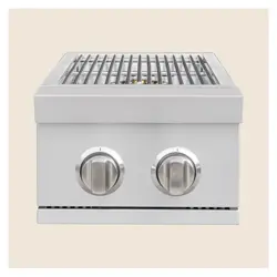
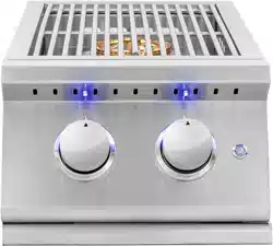
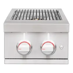
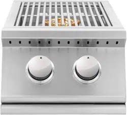
NAME: SINGLE SIDE BURNER / SIZZLER DOUBLE SIDE BURNER / SIZZLER PRO DOUBLE SIDE
BURNER / TRL DOUBLE SIDE BURNER / TRL SEAR SIDE BURNER / ALTURI DOUBLE SIDE BURNER /
ALTURI SEAR SIDE BURNER
PART #: SSSB1 / SIZSB2 / SIZPROSB2 / TRLSB2 / TRLSS / ALTSB2 / ALTSS
Liquid propane & natural gas configurations available
THANK YOU
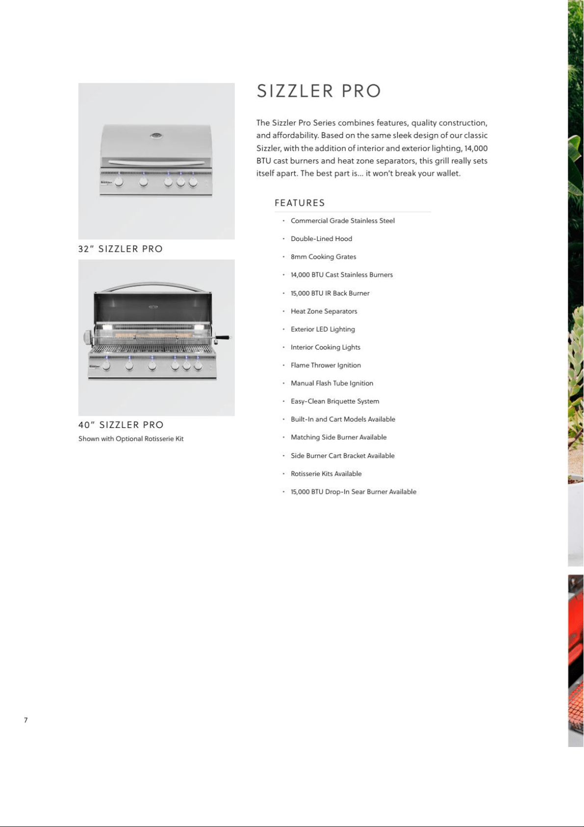
Thank you for your purchase. We’d like to welcome you to the Summerset family of luxury outdoor
kitchen products and look forward to being a part your home for years to come. As a family business
with over 30 years of industry experience, we aim to deliver exceptional quality and personal service.
Welcome to the Summerset family and we hope you love your new Side Burner!
FOR YOUR RECORDS
Please record the following information and refer to it when contacting Summerset Professional Grills
or an authorized dealer. The serial number is located on the rating plate. The rating plate is located on
the exterior basin of the Side Burner and on the underneath side of the drip tray (select models only).

Safety
Warnings
& Codes
1
1. Shut off the gas to the appliance.
2. Extinguish any open flame.
3. Open lid to vent.
4. If odor continues, keep away from the
appliance, and immediately call your gas
supplier or fire department.
IF YOU SMELL GAS
WARNING!
WARNING!
1. Do not store or use gasoline or other
flammable vapors and liquids in the
vicinity of this or any other appliance.
2. A propane cylinder not connected for
use shall not be stored in the vicinity of
this or any other appliance with flame.
WARNING!
Do not store or use gasoline or other
flammable liquids or vapors near this or any
other appliance.
WARNING!
Improper installation, adjustment,
alteration, service, or maintenance
can cause injury or property damage.
For assistance or additional
information consult a qualified
professional installer, service agency, or
the gas supplier.
WARNING!
IMPORTANT: READ THESE INSTRUCTIONS CAREFULLY BEFORE STARTING INSTALLATION
If stored indoors, detach and leave any fuel
cylinders outdoors.
The burning of gas cooking fuel generates some
by-products, which are on the list of substances,
which are known by the State of California to
cause cancer or reproductive harm. California
law requires businesses to warn customers
of potential exposure to such substances. To
minimize exposure to these substances, always
operate the unit according to the use and care
manual, ensuring you provide good ventilation
when cooking.
FAILURE TO READ AND FOLLOW THE “USE
AND CARE” INSTRUCTIONS COULD RESULT
IN A FIRE OR EXPLOSION THAT COULD
CAUSE SERIOUS BODILY INJURY, DEATH OR
PROPERTY DAMAGE.
Always have your Side Burner
vented correctly, installed by a
professional and inspected by the local
city building department.
CODE AND SUPPLY REQUIREMENTS:
These Side Burners must be installed
in accordance with local codes and ordinances, or,
in the absence of local codes, with either the
latest National Fuel Gas Code (ANSI Z223.1/
NFPA 54), and Natural Gas and Propane
Storage and Handling Installation Code (CSA-
B149.1).
FOR OUTDOOR USE ONLY
CALIFORNIA PROPOSITION 65 WARNING
ELECTRICAL PARTS AND COMPONENTS
Disconnect all power supplies and batteries
before servicing.
WARNING!
FLAMMABLE GAS
Disconnect all propane or natural gas
supplies to this unit before servicing .
WARNING!
2

SAFETY AND INSTALLATION WARNINGS
• Have an ABC Fire Extinguisher readily accessible. Never attempt to extinguish a grease fire with
water or other liquids.
• Keep electrical supply cords and fuel supply hoses away from heated surfaces.
• Do not heat unopened food containers as they may explode.
• Never store additional or empty fuel cylinders in the Side Burner cabinet or near the Side Burner. Do
not store cylinders indoors or on their sides. Never use dented, rusty or damaged cylinders.
• Close supervision is necessary when this or any appliance is used near children. Keep children away
from the Side Burner during operation and until the Side Burner has cooled off.
• Do not use aluminum foil to cover cooking grates. This will alter combustion airflow and trap
excessive heat in the control area leading to damaged knobs or igniter modules.
• After the Side Burner is installed by a professional technician be sure they show you where your
gas supply shut-off valve is located. All gas lines must have a shut-off that is easily accessible. If
you ever smell gas, check for leaks IMMEDIATELY. Never check for gas leaks with an open flame.
• Never operate burner in a windy area. If windy conditions exist, install a suitable windbreak.
• Damage caused by leaving operating burner unattended is not covered under the terms and
conditions of the AMD Direct Gold Standard Warranty. Never leave open flame unattended.
• Never use burner without drip pan in place. Make sure drip pan is properly and fully inserted.
Failure to do so may allow hot grease or boil-overs to become a fire or explosion hazard.
• Do not repair or replace any part of the Side Burner unless specifically recommended by this
manual. A qualified technician should perform all other necessary service.
• Summerset Side Burners are not designed/certified for and cannot be installed in or on
recreational vehicles, portable trailers, boats or any other mobile vehicle.
• Children should never be left alone or unattended in an area where a Side Burner is located.
Install your Side Burner well away from areas where children play. Do not store items that may draw
the interest of children in or around the Side Burner, island or masonry enclosure. When in use and
immediately after, areas of the Side Burner are hot enough to cause severe burns!
• Avoid wearing loose-fitting, long sleeves or flammable garments when using the Side Burner.
Never touch cooking grates on top or surrounding metal surfaces with your bare hands as these
areas become extremely hot during use and could cause severe burns. Use an insulated glove or
mitt when attempting to handle parts of the Side Burner.
• Never lean over or look directly over the cooking surface when attempting to light.
• The Side Burner lid must be completely removed before lighting and during operation.
• Do not cover the Side Burner with the lid until the cooking surface has cooled down.
• Never connect any unregulated gas supply to the Side Burner. Supplied regulator must be used in
order to validate warranty.
WARNING!
3

S
I
I
4

SHIPMENT ARRIVING DAMAGED:
VISIBLE DAMAGE
If your shipment arrives with visible damage to
the box/carton, be sure the damage is noted on
the bill of freight or express receipt and signed
by the person making the delivery. File claim for
damages immediately, regardless of the extent
of damage.
CONCEALED DAMAGES
If damages are unnoticed until the Side Burner
is unpacked, notify the transportation company
or carrier immediately and file a c oncealed
damage claim with them. This should be done
within (5) days of the delivery date. Be sure to
hold on to the box/carton for inspection. We
cannot assume responsibility for damage or loss
incurred in transit.
IMPORTANT NOTES:
BE MINDFUL OF WIND DIRECTION
When selecting a suitable location, consider
important factors such as exposure to the wind
and foot traffic patterns. Position your Side
Burner so the prevailing wind blows into the
front control panel (at your back when
operating), allowing for proper front to rear
airflow. Side Burners located in areas with
prevailing winds should be protected by a
wind barrier, wind deflector, or wind guard.
Side Burners are designed to pull in air from
the front and exhaust through the rear of the
unit. Winds hitting the back of the Side
Burner directly may cause problems.
GAS LINE LENGTH
Keep all gas supply lines as short as possible. Gas
lines lose pressure over distance and with each
elbow or “t” fitting added. This drop in pressure
affects Side Burner performance.
PROPER LEVELING
PROPER LEVELING DURING INSTALLATION
IS CRITICAL. A SIDE BURNER THAT IS OUT
OF LEVEL WILL CAUSE ERRATIC BURNER
COMBUSTION AND INEFFICIENT, UNEVEN
HEATING. THE SIDE BURNER SHOULD BE LEVEL
IN ALL DIRECTIONS. ADJUSTMENTS MAY NEED TO
BE MADE EACH TIME WHEN MOVING A
FREESTANDING UNIT.
CONSTRUCTION ZONES
Keep all stainless steel products away from
construction zones. Construction debris such as
(but not limited to) stone dust, stucco, and lime
dust could damage or permanently discolor
stainless steel products. Keep all caustic chemicals
including chlorine and pool cleaning products
away from stainless steel at all times.
IMPORTANT: THIS S BURNER IS
FOR OUTDOOR USE ONLY.
WARNING!
The Side Burner must be installed in
masonry or other type of fireproof surround.
The unit is not insulated and therefore must
be installed or placed with 16” – 18” of side and
back clearance from unprotected combustible
materials such as wood, plastic, or stucco
with wood framing. PLEASE NOTE: if this is
not done the combustible material will catch
on fire a nd potentially d amage your house /
structure and may cause bodily harm due to
the fire.
Do not install this unit under unprotected
flammable surfaces. Do not install or use this
appliance inside a building, garage, or any
other enclosed area. It must not be used in
or on recreational vehicles or boats.
This is a slide-in unit designed to fit into open-
front enclosures. Control panel of the unit is
removable for gas hookup, servicing and
burner adjustment. Control panel must
remain removable aer you install the unit.
Do not have this panel sealed for any reason.
Important: The lip on the side requires 1” ( 2.5
cm) of countertop on each side and back to
support the unit.
Note: We recommend you build the enclosure
for the power burner 6”-12” (15.2 cm- 30.5 cm)
LOWER than your countertop. This will ensure
a safer environment when using tall cooking
pots like the turkey fryer, which can hold 40lbs
of hot flammable oil. Please make sure that
you do not overfill large pots of oil for the oil
will spill over and catch on fire.
Note: This unit should be installed so that
it can be removed at a later date if factory
service is required.
5

re r e aie r er
aae iid r ar ear i r
a er aiae
re are ider der r
ear i aiae
eer i ider re a
aai
ee iri are ed ire
ai eri ir r ee dea a
r
r iaai i ie
ai
ae der reed
eread ie rae
S S
You must maintain proper air flow for your
Side Burner to perform as it was designed
(diagram below). If airflow is blocked,
overheating and poor combustion will result.
Make sure not to block the 1” (2.5 cm) front
air inlet along the bottom of the control panel
or more than 75% of the support grid surface
with pans or griddles.
e: The 1” (2.5 cm) front air space allows access
to the drip tray.
S
SS S
If installed under a patio roof, the cooking
grid area should be fully covered by a chimney
and exhaust hood. An exhaust fan with a
rating of up to 1,000 CFM (472 liters per
second) may be necessary to efficiently
remove smoke and other cooking by-
products from the covered area.
Installation in fully enclosed patio areas is
not recommended.
Ensure the gas supplied meets the minimum
pressure requirements. See below table for gas
requirements measured in water column (w.c.)
pressure:
Gas Type Maximum Minimum
Natural Gas 7” w.c. 4” w.c.
Liquid Propane 14” w.c. 11” w.c.
Both the regulator and burner orifices have
been tuned for the type of gas specified on the
rating plate. Converting to a different type of
gas requires a conversion kit. Conversion kits
are included with this Side Burner and
located with the manual. Converting gases may
require additional parts not included
with this Side Burner. (See Gas Conversion
section for details).
SS
11-3/4"(W) x 9"(H) x 19"(D)
S
11-3/4"(W) x 9"(H) x 19"(D)
SS
10-3/4"(W) x 8"(H) x 20-3/4"(D)
SSS
8"(W) x 2-1/2"(H) x 15-1/2"(D)
SS 10-3/4"(W) x 8"(H) x 20-3/4"(D)
S
13-1/4"(W) x 10-1/4"(H) x 23-1/4"(D)
SS
13-1/4"(W) x 10-1/4"(H) x 23-1/4"(D)
CUTOUT DIMENSIONS
SS
15,000
S
30,000
SS
SSS
24,000
SS 24,000
S
35,000
SS
26,000
TOT UNE TUS
15,000
S S S
Each appliance is set and tested at the factory for
the type of gas supply to be used. Identify the
type of gas, either NG or LP (Liquid
Propane) gas and make sure that the marking
on the rating plate located on the side of the unit
matches the gas being supplied to the side
burner. The rating plate is located on the side of
the Side Burner.
All gas hook up connections should be made by
a qualified technician and in accordance with
local codes and ordinances. The installation
must conform with local codes or, in the absence
of local codes, with either the national Fuel Gas
Code, ANSI Z223.1/NFPA 54, or CAN/CGA-B149.1,
Natural Gas Installation Code or CAN/CGA-B149.2,
Propane Installation Code.
6

Gas Safety
Requirements
7

An enclosure or island for an LP gas cylinder must
be vented on the level of the cylinder valve and at
floor level. The effectiveness of the opening(s) for
purposes of ventilation shall be determined with
the LP gas supply cylinder in place. This shall be
accomplished by one of the following:
a. One side of the enclosure shall be fully open; or
b. For an enclosure having four sides, a top and a
bottom, at least two ventilation openings at
cylinder valve level shall be provided in the
sidewall, equally sized, spaced at 180 degrees (3.14r),
and unobstructed. Each opening shall have a total
free area of not less than 1/2 square inch per pound
(7.1 cm2/kg) of stored fuel capacity and not less than
a total free area of 10 square inches (64.5 cm2).
Ventilation opening(s) shall be provided at floor
level and shall have a total free area of not less
than ½” square inch per pound (7.1 cm2/kg) of
stored fuel capacity and not less than a total free
area of 10 square inches (64.5 cm2). If ventilation
openings at floor level are in a sidewall, there
shall be at least two openings. The bottom of the
openings shall be at floor level and the upper
edge no more than 5 inches (127 mm) above the
floor. The openings shall be equally sized, spaced
at 180 degrees (3.14 r) and unobstructed.
Although LP Gas Cylinders may be used, it is
not recommended due to the large amount of
Gas Consumption and may freeze up the gas
cylinder as well as a safety risk.
1. Provided with a listed overfilling prevention
device.
2. Provided with a cylinder connection device
compatible with the connection for outdoor
cooking appliances.
CHECK TO ENSURE THAT THE GAS SUPPLY
HOSE DOES NOT COME IN CONTACT
WITH ANY HOT SURFACE OF THE S
BURNER.
WARNING!
VENTING YOUR ENCLOSURE:
L GAS
(
LIQUIFIED PETROLEUM /PROPANE
)
If your Side Burner is factory built for LP, the
regulator required is set for 10” water column
and is for use with LP gas only. If unit is NOT
supplied with regulator please make sure that all
requirements are met for the type of regulator
required.
L GAS SAFETY REQUIREMENT
The LP gas supply cylinder must be constructed
and marked in accordance with the
specifications for LP gas cylinders of the U.S.
Department of Transportation (D.O.T.) or the
National Standards of Canada CAN/CSA-B339,
Cylinders, Spheres and Tubes for the
Transportation of Dangerous Goods, and
Commission, as applicable; and
1. This gas appliance and its individual shutoff
valve must be disconnected from the gas
supply piping system during any pressure
testing of that system at the test pressures
in excess of ½ psi (3.5 kPa).
2. This appliance must be isolated from the
gas supply piping system by closing its
individual manual shutoff valve during any
NATURAL GAS INSTALLATION
The installation must conform with local
codes or, in the absence of local codes, with
either The National Fuel Gas Code, ANSI Z223.1/
NFPA 54, or CAN/CGA-B149.1, Natural Gas
Installation Code or CAN/CGA-B149.2, Propane
Installation Code.
It must be provided with a shut-off valve
terminating in gas tank valve outlet. It must
include a collar to protect the cylinder valve. The
cylinder supply system must be arranged for
vapor withdrawal.
Do not operate the gas Side Burner indoors
or in any enclosed area. If the gas Side Burner is
not in use, the gas must be turned off at the
supply cylinder. If the Side Burner is to be stored
indoors, disconnect the gas supply cylinder and
leave the cylinder outdoors.
LP GAS HOOK-UP
A typical LP gas installation is shown below. Make
sure that the factory- supplied regulator is used
and installed with the arrow mark on the
regulator pointing towards the Side Burner. Do not
use any replacement regulator other than that
specified by the manufacturer. Use only pipe
sealants that are approved for use with natural
and LP gases. An installer-supplied
gas shutoff valve must be installed in an accessible
location. (Reference: leak test procedure).
8
Shut off gas to the appliance right
away.
Extinguish any open flame
Make sure the cover is not placed
over the burner
If gas smell continues, keep
away from the appliance and
immediately call gas supplier or
fire department.
IF YOU SMELL GAS
WARNING!
Make sure that the regulator is set for natural gas.
To check, remove the top cap. You will find the
conversion plastic pin attached to the cap to the
underside of the cap. If the disc (1/2 in. diameter)
of the pin is close to the cap, then the regulator
is set for natural gas. If the disc is at the tip of the
pin, away from the brass cap, the regulator is set
for system LP application. To convert to natural
gas, remove the plastic conversion pin and invert
and replace it back in a manner such that the disc
is close to the brass cap. For both NG and LP, the
maximum inlet pressure is 14” water column. Make
sure that the factory-supplied regulator is used
and installed with the arrow mark on the
regulator pointing towards the gas Side Burner.
Do not use any replacement regulator other
than that specified by Summerset. Use only pipe
sealants that are approved for use with NG and
LP gases. An installer-supplied gas shutoff
valve must be installed in an accessible location.
pressure testing of the as supply piping
system at test pressures equal to or less
than 1/2 psi (3.5 kPa). If the gas Side Burner
is factory built for natural gas, the regulator
supplied is set for 4” water column. The
regulator is convertible Later to 10” water
column for system LP application. Do not
use with a 20-lb LP cylinder.
CAUTION BEFORE TESTING
Finding and/or fixing a gas leak is NOT a
“DO-IT-YOURSELF” procedure.
NEVER USE THE S BURNER WITHOUT
FIRST LEAK TESTING THE GAS
CONNECTIONS.
WARNING: DO NOT USE OPEN FLAME TO
CHECK FOR LEAKS. USE OF AN OPEN FLAME
COULD RESULT IN A FIRE, EXPLOSION AND
BODILY HARM.
DO NOT SMOKE WHILE PERFORMING THE LEAK
TEST!
IF AT ANYTIME YOU SMELL GAS – SWITCH
OFF ALL OF YOUR EQUIPMENT AND CALL A
PROFESSIONAL TO DETECT THE GAS LEAK.
ALWAYS INFORM ALL MEMBERS OF YOUR
FAMILY ABOUT THIS IMPORTANT FACT – SMELL
GAS = DO NOT USE THE EQUIPMENT.
To prevent fire or explosion hazard, DO NOT use
or permit sources of ignition in the area while
performing a leak test. Perform leak test outdoors
only. Check to ensure that flexible hoses do
not have any cuts and wear that may affect the
safety before each use. Only the factory supplied
regulator must be used. Use only replacement
regulator specified by the manufacturer.
A minimum clearance of 1” from the back of
the Side Burner above cooking surface to non-
combustible construction is required.
A minimum of 1” clearance to the sides of the
Side Burner above cooking surface to non-
combustible construction is recommended.
1. Prepare a leak testing solution of soap and
water in a spray bottle (50% solution)
2. Confirm that all control knobs are in the off
position.
3. Turn the main gas supply valve ON.
4. Apply the leak test solution by spraying on
all of the pipe joints, fittings and hoses.
5. A gas leak is detected when:
• There is a faint smell of gas and/or
• There are bubbles around the connections.
6. DO NOT ATTEMPT TO IGNITE THE BURNER.
7. Turn off the main gas supply.
8.
9.
Call a certified/qualified professional to
repair the GAS LEAK.
DO NOT attempt to use the Side Burner
until the leak is fixed.
S
9

Cleaning &
Maintenance
10

1. The smell of gas in conjunction with the
burner flames appearing yellow.
2. The Side Burner does not reach
temperature.
3. The Side Burner heats unevenly.
4. The Side Burner makes popping noises.
NOTE:
It is recommended to build the Side Burner at
least 6”-12” lower than the counter-top.
SPIDER AND INSECT WARNING
Spiders and other insects can nest in the burner
of this and any other Side Burner, which causes
the gas to flow from the front of the burner.
This dangerous “condition” can cause a fire
behind the valve panel, damaging the Side
Burner and making the Side Burner unsafe to
operate. Inspect the burners once a year or if
the Side Burner has not been used for more
than one month or if any of the following
conditions occur:
STAINLESS STEEL MAINTENANCE
The Side Burner is made of stainless steel
construction. It is non-rusting. Never clean the
stainless steel when it is hot. After the initial
cooking use, certain areas of the Side Burner
may discolor. This is a normal discoloration
caused by the internal heat given off by the
burner. Specks of grease can gather on the
surface of the stainless steel and get baked-on.
These can be removed by using a mild abrasive
pad (like Scotch Brite) with a stainless steel
cleaner. Use the mildest cleaner and always scrub
in the direction of the grain.
Do not use steel wool to clean the Side Burner. Do
not use abrasives on the polished highlights.
Be extra careful when cleaning around the
highlights. Metal polisher or mild chrome cleaner
can be used to bring back the luster on highlights.
To touch-up minor scratches in the stainless steel,
sand the affected surface very lightly, with 100-dry
grit emery sandpaper in the direction of the grain.
S BURNER GRATE MAINTENANCE
The easiest way to clean the grates is to scrub
them with a barbecue brush immediately aer
cooking is completed and the flame is turned off.
Wear a heat protective barbecue mi t o p r o t ect
your hands from the heat and steam. Dip a brass
bristle barbecue brush in tap water and scrub the
hot grates. Dip the brush frequently in tap water.
Steam, created as water comes in contact with
the hot Side Burner, helps loosen food particles
stuck in the Side Burner. These food particles
will either get burned or fall into the cleaning pan.
Cleaning of the Side Burner would be longer
and more difficult if the Side Burner grates are
allowed to cool before cleaning.
BURNER CLEANING & MAINTENANCE
Burners are made of heavy gauge brass and can
be cleaned using a bristle brush, warm water
and soap. Check every porthole for clogs. Use a
wire pin to clean out clogged ports. Make sure
the burner is dry before installing it back to the
Side Burner.
The drip pan collects grease, liquid and fallen
food particles. Allow the pan and its contents to
cool before cleaning. Slide the pan out and wipe it
clean. Make sure the drip pan is fully inserted back
into the Side Burner. It is highly recommended to
clean the pan after every use to avoid any
possibility of a grease fire. DO NOT use the Side
Burner without the drip pan pushed all the way to
the back of the Side Burner unit.
OPERATING INSTRUCTIONS
BEFORE LIGHTING THE S BURNER
DO NOT ATTEMPT TO LIGHT THE S
BURNER IF YOU SMELL GAS.
WARNING! IT IS CRITICAL THAT THE GAS
BURNERS ARE PROPERLY INSTALLED WITH
THEIR ORIFICES INSIDE THE BURNERS AIR
SHUTTERS. If not properly installed, gas may
leak outside of the burner that could lead to
fire, potential damage to your Side Burner
and bodily injury.
11
Inspect the gas supply piping or hose prior to
turning the gas ON. If there is evidence of cuts,
wear, or abrasion, it must be replaced prior to
use. The replacement pressure regulator and
hose assembly must be the type specified by the
manufacturer. Do not use the Side Burner if the
odor of gas is present. The pressure regulator
and hose assembly supplied with the units must
be used. If the unit is LP, screw the regulator and
hand tighten to the valve of the cylinder and leak
check the hose and regulator connections with
a soap and water solution before operating the
Side Burner. Make sure you always read about
LEAK PREVENTION. Always keep your face and
body as far away as possible when lighting.
Refer to spiders and insects warning and
procedure under the cleaning and maintenance
page of this manual.
FOR OUTDOOR USE ONLY!
ASSEMBLY & LIGHTING
Remove all packing materials.
Ensure that the burners are positioned securely
on their orifices.
Place grates in the proper location over burners.
Connect gas using proper gas regulator.
1. Open the gas supply shut-off valve.
2. Push in the knob to the left wait a few
seconds and then click the flame-thrower
ignition system to ignite. If the igniter does
not light turn to the right and OFF position,
verify that the gas is on and then try again.
3. Once you see or hear a flame you can
adjust the burner to the desired position.
CAUTION: If ignition does not take place within a
few clicks, turn knob to the OFF Position, wait for
five minutes and repeat step 2.
Match/BBQ Lighter Lighting Instructions:
The burners can be lit manually using a lighted
long match, taper or long BBQ lighter.
1. Push and turn the knob counter-clock-wise
past the “CLICK” position. Hold the knob
pushed in for 5 seconds.
2. Insert a lit match or BBQ lighter through the
grates and near the top of the burner. Once
you see or hear a flame you can release the
knob.
Important: If burner fails to light within 5 seconds,
turn off gas and wait 5 minutes before repeating
the process.
Warning: If you smell gas, shutoff the gas supplies
and immediately checks for leaks using the
soapy water technique.
CONNECTING TO THE LP TANK
The hose and regulator are connected in the
following manner:
• Insert the regulator inlet into the cylinder
valve and turn the black coupling nut
clockwise until the coupling nut is
hand tight. DO NOT over-tighten this
connection.
• To disconnect the coupling nut, first make
sure the main cylinder valve is turned off.
Grasp the coupling nut and turn counter
clockwise. The inlet will then disengage.
FILLING AND REFILLING LP GAS CYLINDERS
All purging and refilling of LP gas cylinders
must be performed by qualified personnel in
the LP gas industry. Never store a spare LP gas
cylinder under or near this appliance.
Never fill the LP gas cylinder beyond 80 percent
full. Failure to follow these instructions may
result in explosion, personal injury or death.
ALWAYS WAIT 5 MINUTES BEFORE RE-
LIGHTING A HOT BURNER!
NOTE
Improper lighting procedures can cause the
flow control to activate, resulting in reduced
heat output. If this is suspected, shut off all
burner controls and cylinder valve. Wait 30
seconds, then very slowly re-open cylinder
valve. Wait an additional 5 seconds before
turning burner control knob and attempting
to light.
12
LP gas Side Burner models are designed for
use with a standard 20 lb. liquid propane gas
(LP) tank with type (1) valve connections. (Not
included)
Never connect your gas grill to an LP tank that
exceeds this capacity. A tank of approximately
12 inches in diameter by 18-1/2 inches high is
the maximum size LP gas tank to use. A propane
tank with an OPD (Overfill Prevention Device)
must be used. This safety feature prevents the
tank from being over-filled which can cause
malfunction of the LP gas tank, regulator and/or
grill.
The LP cylinder must be constructed and marked
in accordance with the specifications for LP gas
cylinders of the U.S. Department of Transportation
(DOT) and designed for use with a Type 1 system
only. Be sure to read and follow all LP
connection instructions.
A dented or rusty LP cylinder may be hazardous
and should be avoided. If in doubt, have it
checked by your LP supplier. Always check for leaks
aer every LP cylinder change. (See Checking For
Leaks)
Cylinders must be stored outdoors in a well-
ventilated area out of the reach of children. If your
grill is stored indoors, the LP cylinder must be
stored outside, in upright position and away from
excessive heat.
CONNECTING TO A SIDE BURNER
You will need a ‘T’ adapter fiing (not provided)
or similar connection to connect a single gas line
to both a Side Burner and a grill. See
figure below. We recommend a licensed gas
technician install all gas lines.
IMPORTANT
All installation and all installation parts must
conform to local codes with the National
Electrical Code, ANSI Z223.1/ NFPA 70 latest
edition and the National Fuel Gas Code ANSI
Z223.1/NFPA 54 in the U.S. and CGA-B149.1/.2
in Canada
LIQUID PROPANE INSTALLATION
NOTE: Ventilation is required in
the enclosure on opposite sides to
create cross-ventilation. Liquid propane is
heavier than natural gas and vents should
be located near the bottom of the enclosure.
Before lighting the burners, inspect the gas
supply piping or hose. If there is evidence of
cuts, wear, or abrasion, it must be replaced
prior to use. Always keep your face and body
as far away from the grill as possible when
lighting.
WARNING!
Shown with Grill
13

S
D
14
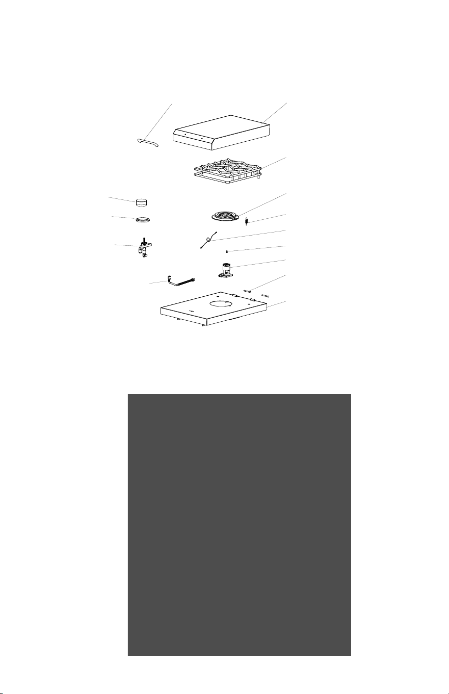
SINGLE SIDE BURNER
PARTS LIST & LINE DRAWING
LID HANDLE
LID
GRATE
BURNER
IGNITER
IGNITER WIRE
ORIFICE
BURNER BASE
LID HINGE PIN
BODY
FLEX TUBE
VALVE
KNOB
KNOB BEZEL
15
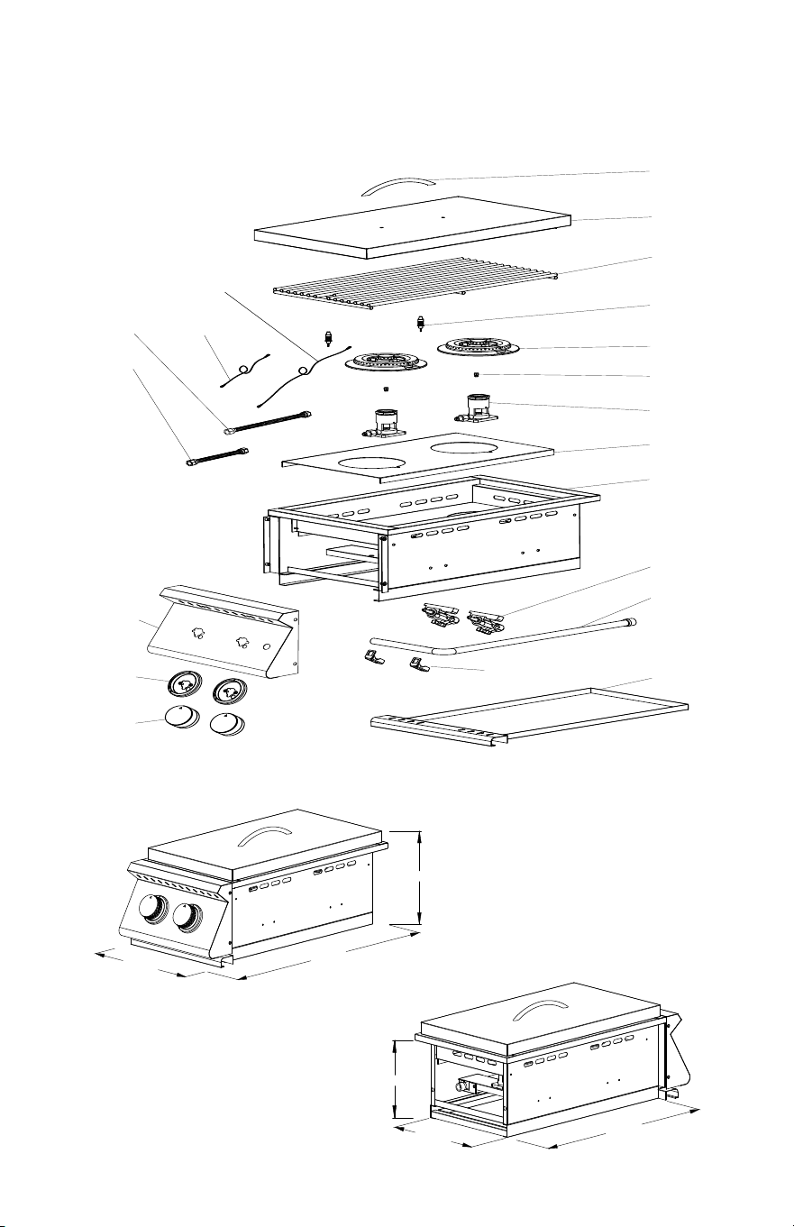
12
5/8"
25
3/8"
9 5/8"
20 5/8"
10 1/2"
7 3/4"
LID HANDLE
LID
GRATE
IGNITER
BURNER
ORIFICE
BURNER BASE
BODY
VALVE
MANIFOLD
DRIP TRAY
KNOBS
KNOB BEZELS
FRONT PANEL
FLEX TUBE 200mm
FLEX TUBE 400mm IGNITER WIRE
330mm
IGNITER WIRE
480mm
BURNER PLATE
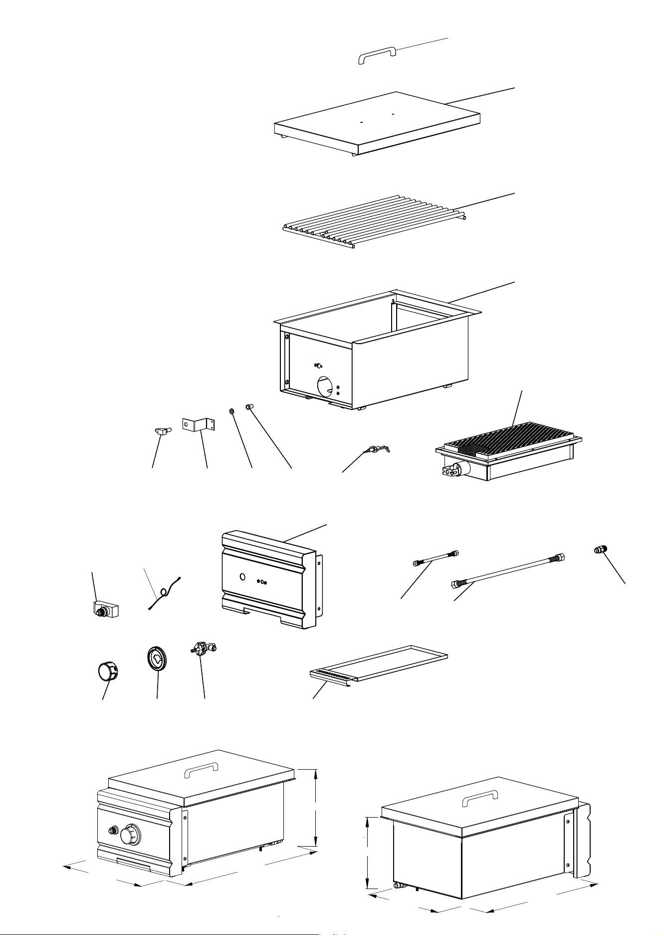
SIZZLER DOUBLE SIDE BURNER
PARTS LIST & LINE DRAWING
VALVE LATCH
16
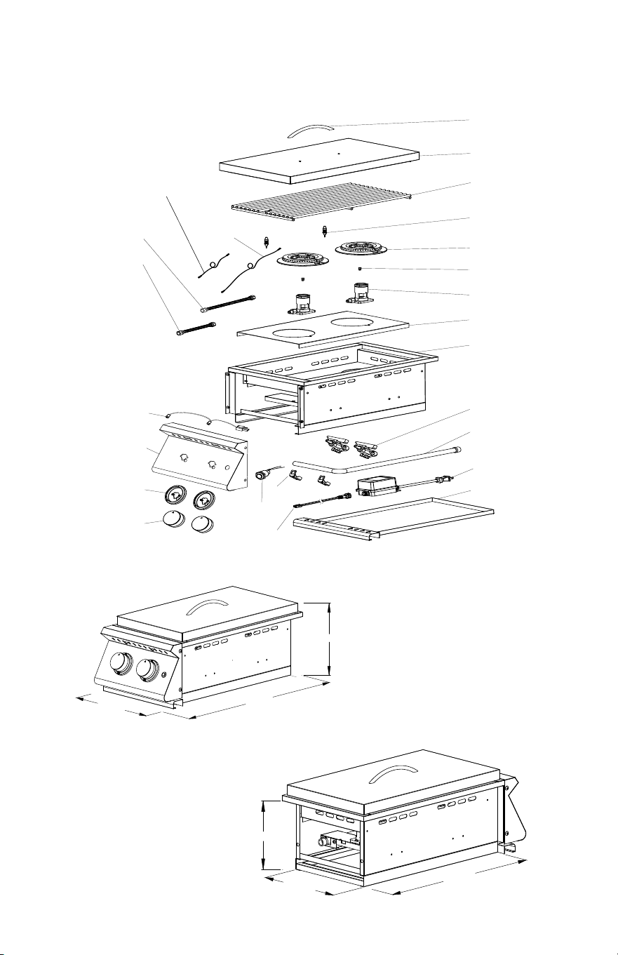
12 5/8"
25 3/8"
9 5/8"
7 3/4"
10 1/2"
20 5/8"
LID HANDLE
LID
GRATE
IGNITER
BURNER
ORIFICE
BURNER BASE
BODY
VALVE
MANIFOLD
DRIP TRAY
KNOBS
KNOB BEZELS
FRONT PANEL
FLEX TUBE
SHORT
FLEX TUBE
LONG
IGNITER WIRE
SHORT
IGNITER WIRE
LONG
BURNER PLATE
LED WIRE
LED SWITCH
TRANSFORMER
VALVE LATCH
SIZZLER PRO DOUBLE SIDE BURNER
PARTS LIST & LINE DRAWING
TRANSFORMER
WIRE
17
13 7/8"
23 1/2"
10 7/8"
8 3/4"
11 1/2"
18 5/8"
LID HANDLE
LID
GRATE
IGNITER
BURNER
ORIFICE
BURNER BASE
BODY
VALVE
MANIFOLD
KNOB BEZELS
FRONT PANEL
KNOBS
FLEX TUBE
200mm
FLEX TUBE
400mm
21
22
T-FITTING
RUBBER HOSE
LED LIGHT WIRE
LED LIGHT BASE
TRL DOUBLE SIDE BURNER
PARTS LIST & LINE DRAWING
VALVE LATCH
18
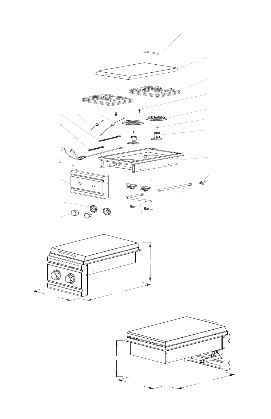
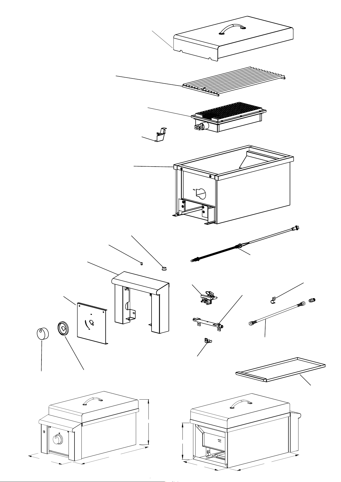
LID HANDLE
LID
GRATE
BODY
IR BURNER
ORIFICE
RIGHT
ANGLE
ORIFICE
MOUNTING
PLATE
BRASS NUT
IGNITER PIN
KNOB KNOB BEZEL VALVE
DRIP TRAY
FLEX TUBE SHORT
FLEX TUBE LONG
BRASS INLET
FITTING
ORIFICE
FRONT PANEL
IGNITER BUTTON
IGNITER WIRE
TRL SEAR SIDE BURNER
PARTS LIST & LINE DRAWING
23 1/4"
13 3/4"
10
"
11 1/2"
18 5/8"
8 3/4"
19
LID
GRATE
BURNERS
IGNITER PINS
ORIFICES
BODY
IGNITER WIRE - SHORT
IGNITER WIRE - LONG
FLEX LINE - LONG
FLEX LINE - SHORT
LED WIRE
LED LIGHT BULBS
BULL NOSE
FRONT PANEL
KNOB BEZELS
KNOBS
LED SWITCH
VALVES
MANIFOLD
VALVE LATCH
FLEX LINE BRACKET
FLEX LINE & FITTING
DRIP TRAY
TRANSFORMER WIRE
TRANSFORMER
ALT
PARTS LIST
ALTURI DOUBLE SIDE BURNER
PARTS LIST & LINE DRAWING
20
WIRE PROTECTIVE SLEEVE
LED PLUG & WIRING
KNOB
KNOB BEZEL
VALVE
VALVE LATCH
FLEX LINE & FITTING 650mm
MANIFOLD
DRIP TRAY
GRATE
IR BURNER
FLASH TUBE
BODY
BULL NOSE
FRONT PANEL
FLEX LINE BRACKET
LID
LED LIGHT BASE
ALTURI SEAR SIDE BURNER
PARTS LIST & LINE DRAWING
21

GOLD STANDARD
LIFETIME
WARRANTY
GOLD STANDARD
WARRANTY
AMD DIRECT GAS APPLIANCES
(GRILLS, SIDE/POWER BURNERS,
GAS GRIDDLE & OVEN)
Yo u r i n ve st me nt i n AM D Di re c t p r o d uc ts i s ba ck e d
by the strongest warranty in the industry. In
addition to precision engineering and outstanding
performance, AMD Direct products include our
GOLD STANDARD LIFETIME WARRANTY with all
replacement parts 100% non-prorated. Eective
with purchases as of 3/1/23.
• Gold Standard Lifetime Warranty on Construction and Manufacturer Defects
• Gold Standard Lifetime Warranty on Stainless Steel Construction
• Gold Standard Lifetime Warranty on Cooking Grates, Burners, Burner
Covers, Valves, Flame Tamers, and Heat Zone Separators, Temperature
Gauges, & Hood Springs
• Gold Standard Lifetime Warranty on Briquette Systems
• 3 Year Warranty on all Other Parts, Components, & Electrical, Including: LED
Bulbs, Wire Harness, & Switches; Power Source Wire; Transformer; Interior
Halogen Light Wire & Bulb
DRAWERS, DOORS, GRILL LINERS, & CARTS
• Gold Standard Lifetime Warranty on Construction,
Workmanship and Materials for all Stainless Steel Parts,
Including Doors, Drawers, Grill Liners, & Carts
• 3 Year Warranty on Electrical (Warming Drawers)
COVERS
• Gold Standard Lifetime Warranty on Covers, Including Grills,
Carts, Side/Power Burners, Gas Griddle & Oven
COMMERCIAL APPLICATIONS
GAS GRILLS
• Gold Standard Lifetime Warranty on Workmanship, Construction,
& Manufacturer Defects for All Commercial and/or Hospitality
Applications
• Warranty is Void Upon Misuse, Including Lack of Regular
Cleaning, Vandalism, or Theft
• Warranty is Valid Only if Regular Maintenance is Exercised. Due
to the Nature of Commercial Applications (Multiple Users, Lack
of Control of Use, etc.) Regular Maintenance is Mandatory
VER 10.25.23
VENT HOODS, REFRIGERATION,
COLD STORAGE & SINKS
VENT HOODS
• 5 Year Warranty on all Stainless Steel Construction
• 3 Year Warranty on Blowers, LED Lighting, Wiring Harness and Switches
15" & 24" REFRIGERATION MODELS
• 3 Year Warranty on all Construction Including Compressors
• 1 Year Warranty on Transformer, LED Bulbs, LED Harness, Power Source
Wire, LED Switches, Interior Halogen Light Wire/Bulbs
21" REFRIGERATION MODELS
• 1 Year Warranty on all Construction & Electrical Components Including
Compressor, Transformer, LED Bulbs, LED Harness, Power Source Wire,
LED Switches, Interior Halogen Light Wire/Bulbs
COLD STORAGE & SINKS
• Gold Standard Lifetime Warranty on Ice Chests
• Gold Standard Lifetime Warranty on Drains & Faucets
AMD Direct Warranty is valid for original purchaser
at original site of delivery with proof of purchase
and photo documentation only. Registration form
must be submitted online within 30 days of the
purchase date to validate the warranty. Warranty is
void upon transfer of ownership. Warranty does not
apply to products installed in any commercial,
rental, or nonresidential application that have not
maintained proper upkeep. Warranty covers
replacement parts only. Manufacturer is not
responsible for labor or labor-related costs.
Warranty does not cover discoloration, surface rust,
corrosion, or oxidation, which may occur due to
harsh environments, chemicals, or overheating.
Warranty will not apply for damage resulting from
improper installations, abuse, extreme
environments, grease fires, or misuse. Proof of
regular and proper maintenance is required.
Coastal, humid, and/or salt environments are
subject to manufacturer review. All out-of-box
claims must be made within 30 days of purchase
and must be made prior to installation. Any product
installed damaged will be considered damaged
during installation and not covered under warranty.
Warranty and registration forms are available at
www.amddirect.com/register. Please be advised -
all display models are sold “as is” and the warranty
covers the following items only: main burners (Gold
Standard Lifetime Warranty), grates (Gold Standard
Lifetime Warranty), burner covers (Gold Standard
Lifetime Warranty). All warranties are subject to the
review and approval of the manufacturer.
14520 DELTA LANE SUITE 105,
HUNTINGTON BEACH, CA 92647
800.966.8126
AMDDIRECT.COM

14520 Delta Ln
Suite 105
Huntington Beach, CA 92647
(
800
)
966-8126
AMDDIRECT.COM
VER. 122122