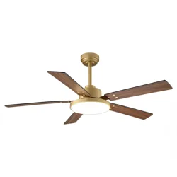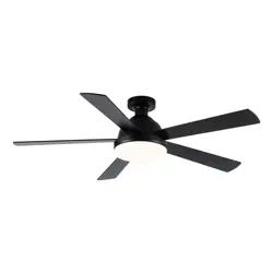
VZA01N105A-BLE
READ AND SAVE THESE INSTRUCTIONS
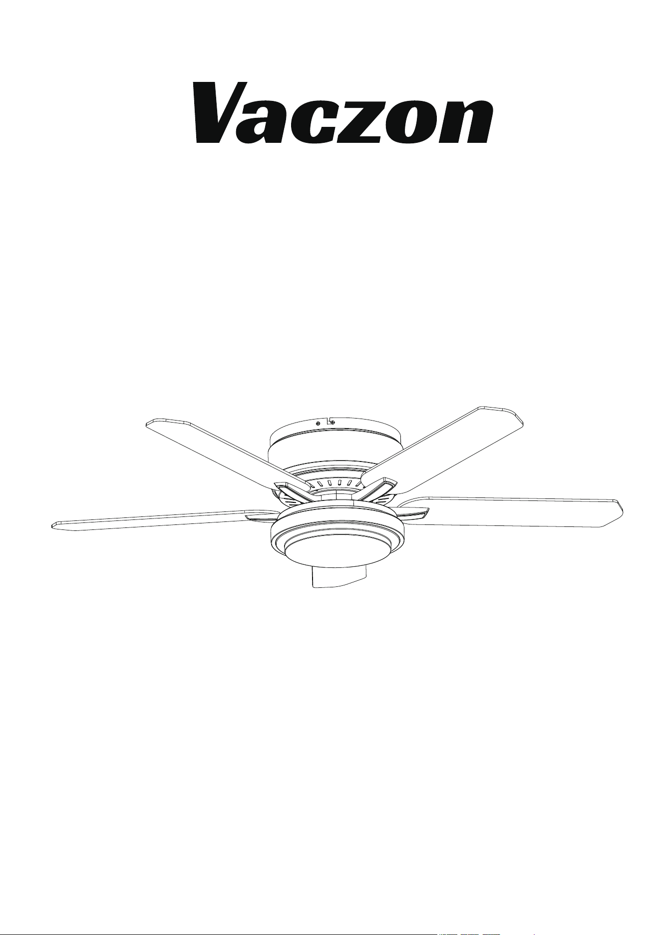
CEILING FAN INSTALLATION MANUAL

CONTENTS
01 IMPORTANT SAFETYINSTRUCTIONS 1
02 PACKAGE CONTENTS
2
03 BEFORE INSTALLATION
3
04 ASSEMBLING THE CEILING BRACKET
4
05 HANGING YOUR CEILING FAN BODY
4-5
06 ASSEMBLING THE DECORATIVE COVER
5
07 ASSEMBLING THE BLADES
6
07 ASSEMBLING THE LIGHT KIT
6
08 ASSEMBLING THE LIGHT SHADE
7
09 PRODUCT SIZE
8
10 REMOTE CONTROL OPERATION
9-10
11 WARNING
11
12 FCC STATEMENT
11
13 APP OPERATION
12
14 CLEANING AND MAINTENANCE
13
15 TROUBLESHOOTING
13
1
1. WARNING: To reduce the risk of fire, electric shock, or personal injury, mount directly to a structural framing member
or to an outlet box marked acceptable for fan support of 15.9kg (35 lbs). For outlet box mounting, use mounting screws
provided with the outlet box.
2. To avoid possible electrical shock, before installing or servicing your fan, disconnect the power by turning off the
circuit breakers to the outlet box and associated wall switch location. If you can not lock the circuit breakers in the off
position,
securely fasten a prominent warning device, such as a tag, to the service panel.
3. To reduce the risk of electric shock, this fan must be installed with an isolating wall control/switch.
4. WARNING: To reduce the risk of personal injury, do not bend the blade brackets when instaling the blade brackets,
balancing the blades, or cleaning the fan. Do not insert foreign objects in between rotating fan blades.
5. This appliance can beused by children aged from 8 years and above and persons with reduced physical, sensory or
mental capabilities or lack of experience and knowledge if they have been given supervision or instruction concerning
use of the appliance in a safe way and understand the hazards involved. Children shall not play with the appliance.
Cleaning and user maintenance shall not be made by children without supervision. It is recommended that children be
supervised to ensure that they are not using the appliance improperly.
6. WARNING: To reduce the risk of fire or electric shock or injury to persons, do not use replacement parts that have
not been recommended by the manufacturer (e.g.parts made at home using a 3D printer).
7. Read all instructions and safety information before installing your new fan. Review the accompanying assembly
diagrams.
8. Before installing the fan, disconnect the power by removing fuses or turning off circuit breakers.
9. Make sure all electrical connections comply with local law and the national electrical code. Please hire a qualified
electrician or consult a do it yourself wiring handbook if you are unfamiliar with installing electrical wiring.
10. Make sure the instalation site is roomy enough to allow fan blades to rotate. There is at least seven feet from the
floor to fan blades' tips.
11. If you are mounting the fan on a celing outet box, please use a metal outlet box. Secure the box directly to the
building structure. The outlet box and its support must be able to support the rotating fan (at least 35Ibs). Do not use a
plastic outlet box. Attach the mounting bracket using the ceiling outlet box's hardware.
12. After installing the fan, make sure all the connections are secured so that the fan won't fall.
13. Do not insert anything between fan blades while the fan is operating.
14. Turn the fan off and wait for it to stop before reversing fan's rotating direction.
15. WARNING: To reduce the risk of electrical shock and personal injury, do not install the fan on a sloped ceiling and
do not use this fan with any solid-state fan speed control device, or rheostat. You must install the outlet box using the
two steel screws and lock washers coming with the fan.
16. All wiring must be in accordance with national and local electrical codes ANSI/NFPA70. If you are unfamiliar with
wiring, use a qualified electrician.
17. After making the wire connections, the wires should be spread apart with the grounded conductor and the equipme-
nt-grounding conductor on one side of the outlet box and the ungrounded conductor on the other side of the outlet box.
18. The splices after being made should be turned upward and pushed carefully up into the outlet box.
19. Instructions for supply connections: the white conductor of a fan identified as grounded conductor to be connected
to a grounded conductor of power supply, the black conductor of fan identified as ungrounded conductor to be connect-
ed to an ungrounded conductor of power supply, the green conductor of fan identified for equipment grounding to be
connected to an equipment-grounding conductor.
20. When mounted directly to the building structure, appliance installation shall not expose combustible material and
do not install the appliance to a ceiling with combustible finish. The installation of the appliance can not leave the
wood of the rafters or any thermal insulation exposed to the interior of the room.
21. To reduce the risk of electric shock, disconnect the electrical supply circuit to the fan before instaling light kit.
IMPORTANT SAFETYINSTRUCTIONS
SPECIFICATIONS
SKU#
Fan Blade Span
120VAC 60HzVZA01N105A-BLE
53W(Fan35W,Lamp18W)
Voltage
Rated Wattage52"
1635CFM
45db(A)
RPM
Number of rotating blades 5 blades
105-195rpmAverage Airlow
Maximum Noise
2
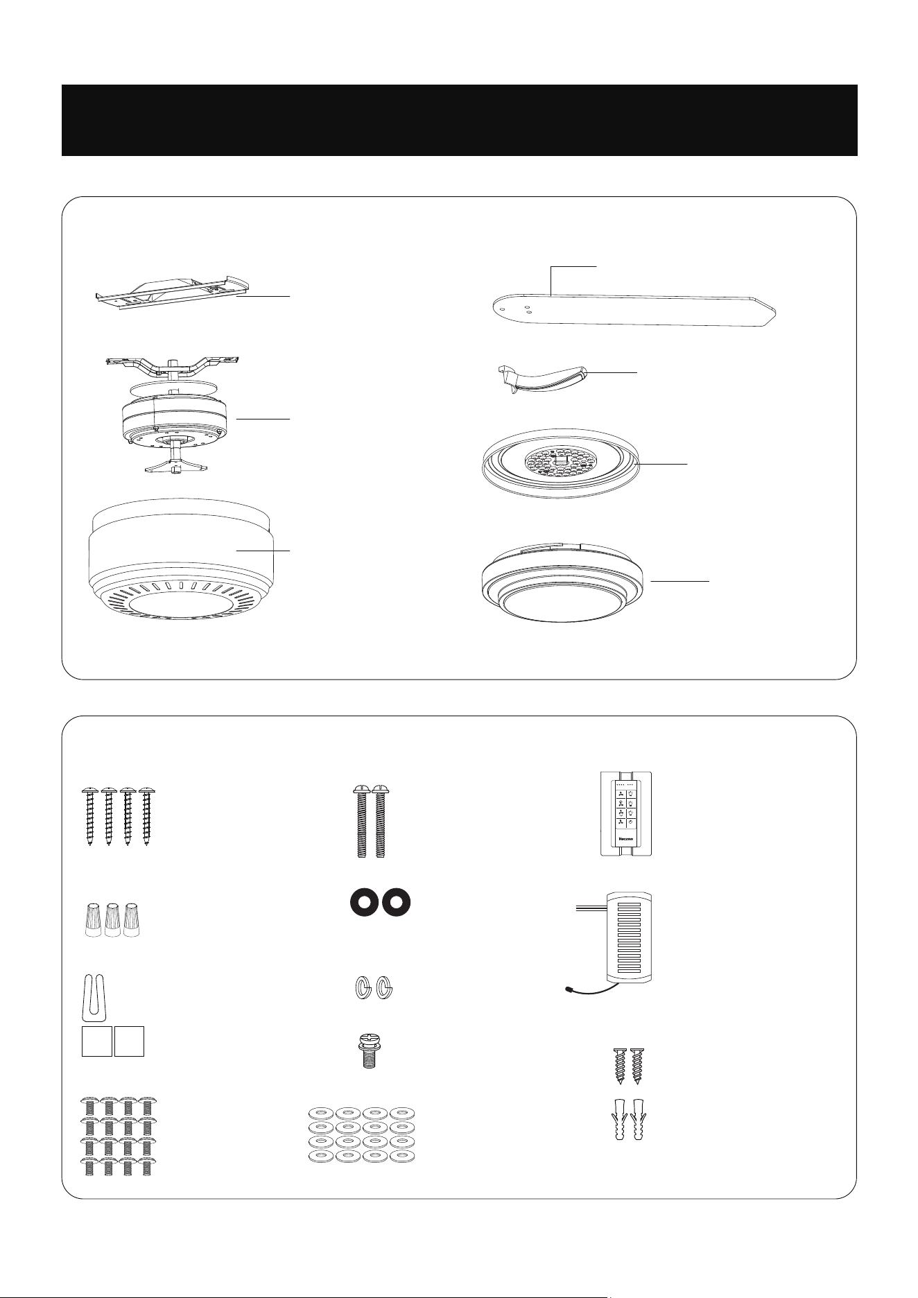
1 X Ceiling Bracket
PARTS
1 X Ceiling Fan Body
1 X Decorative cover
5 X Mounting Brackets
1 X Light Kit
1 X Light Shade
5 X Blades
ACCESSORIES
PACKAGE CONTENTS
4 X ST5 X 35mm
Wood screws
3 X
Plastic wire nuts
1 X
Balanced parts package
16 X M5 X 6 mm
Blade screws
2 X 8-32UNC X 32mm
Mounting screws
2 X
Ø16 X Ø4.5 X 1.5mm
Washers
2 X M4
Spring washers
16 X
Φ12 * Φ5 * 1mm
Blade Washers
REV
ON/OFF ON/OFF
1H/2H/4H/8H
1 X Controller
1 X
Remote control &
Remote control holder
(Battery included)
2 X
Screws
2 X
Expansion screws
K
+
-
1 2 4 8
1 X
1/4” X 12mm
Blade bracket screws
3
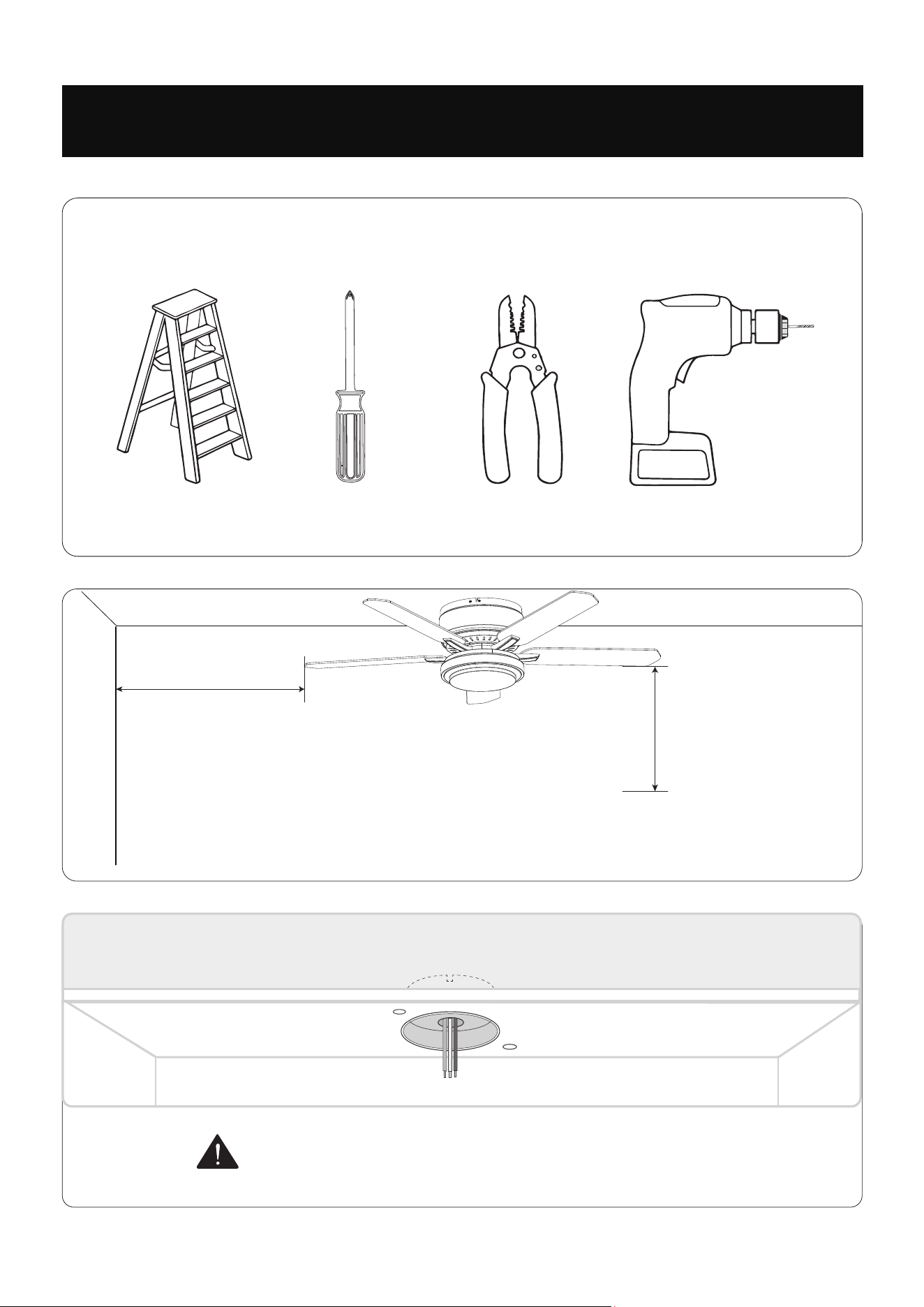
TOOLS NEEDED (NOT INCLUDED)
Ladder Phillips Screwdriver Wire Stripper Drill
CHECK THE ROOM DIMENSIONS
30 inches
from blade tip to nearest
wall or obstruction
7 feet
from bottom edge
of blade to the floor
You must be able to secure the fan to building structure or fan-rated outlet box.
BEFORE INSTALLATION
WARNING: CHECK THE OUTLET
4
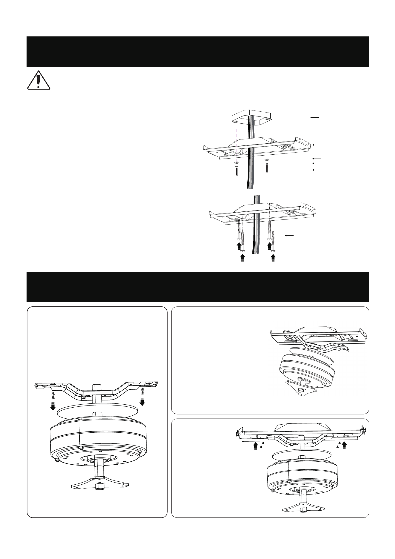
Step 1:
Use a Phillips screwdriver to remove
4 screws from the bracket of the
ceiling fan body and place them for
subsequent installation .
Step 2:
Insert the left of the bracket
of the ceiling fan body into
the left of the mounting bracket,
and then insert the right of the
bracket of the ceiling fan body
into the right of the mounting
bracket until the four holes on
the bracket of the ceiling fan
body align the mounting
bracket.
Step 3:
Use the 4 screws
removed to lock
them and tighten
firmly.
ASSEMBLING THE CEILING BRACKET
HANGING YOUR CEILING FAN BODY
WARNING:
To avoid possible electrical shock, before installing your ceiling fan, disconnect the power by turning off the circuit
breakers to the outlet box associated with the wall switch location.
Option 1: Concrete ceiling
Use 2 mounting screws and washers provided when:
Securing to existing ceiling fan-rated outlet box.
Make sure it is securely installed and is acceptable
for fan support of 15.9kg (35 lbs) or less.
Option 2: Wood ceiling
Use 4 wood screws when:
Securing to support structure with apporved electrical
outlet box. Drill 4 holes in support structure to aid in
securing ceiling bracket.
Wood Screws
Outlet Box (Not Included)
Ceiling Bracket
Washers
Spring washers
Mounting screws
5
HANGING YOUR CEILING FAN BODY
ASSEMBLING THE DECORATIVE COVER
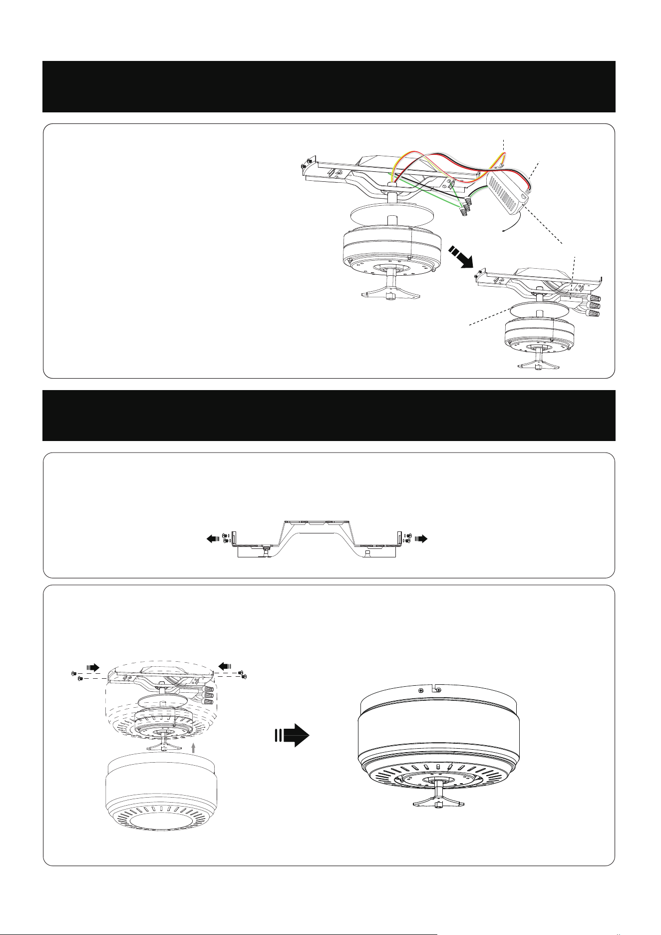
a. Connect the wires (white to white, black to
black) from the ceiling to the controller using
wire nuts.
b. Connect the three grounding wires (green)
coming from the ceiling, controller, and ceiling
fan body using a wire nut.
c. Insert the motor wires and light wires to
the controller.
d. Put the controller on the plate of the ceiling
fan body.
WIRING MUST BE UP TO CODE. All wiring
must be in accordance with national and
local electrical codes. If you are unfamiliar
with wiring or in doubt, consult a
qualified electrician.
Step 4:
Step 1:
Use a Phillips screwdriver to remove 4 screws from the mounting bracket and place them for subsequent
installation .
Step 2:
Use a Phillips screwdriver install the decorative cover to the mounting bracket with 4 removed screws and
washers and tighten them.
Light wires
Motor wires
Controller
Plate
6
ASSEMBLING THE BLADES
ASSEMBLING THE LIGHT KIT
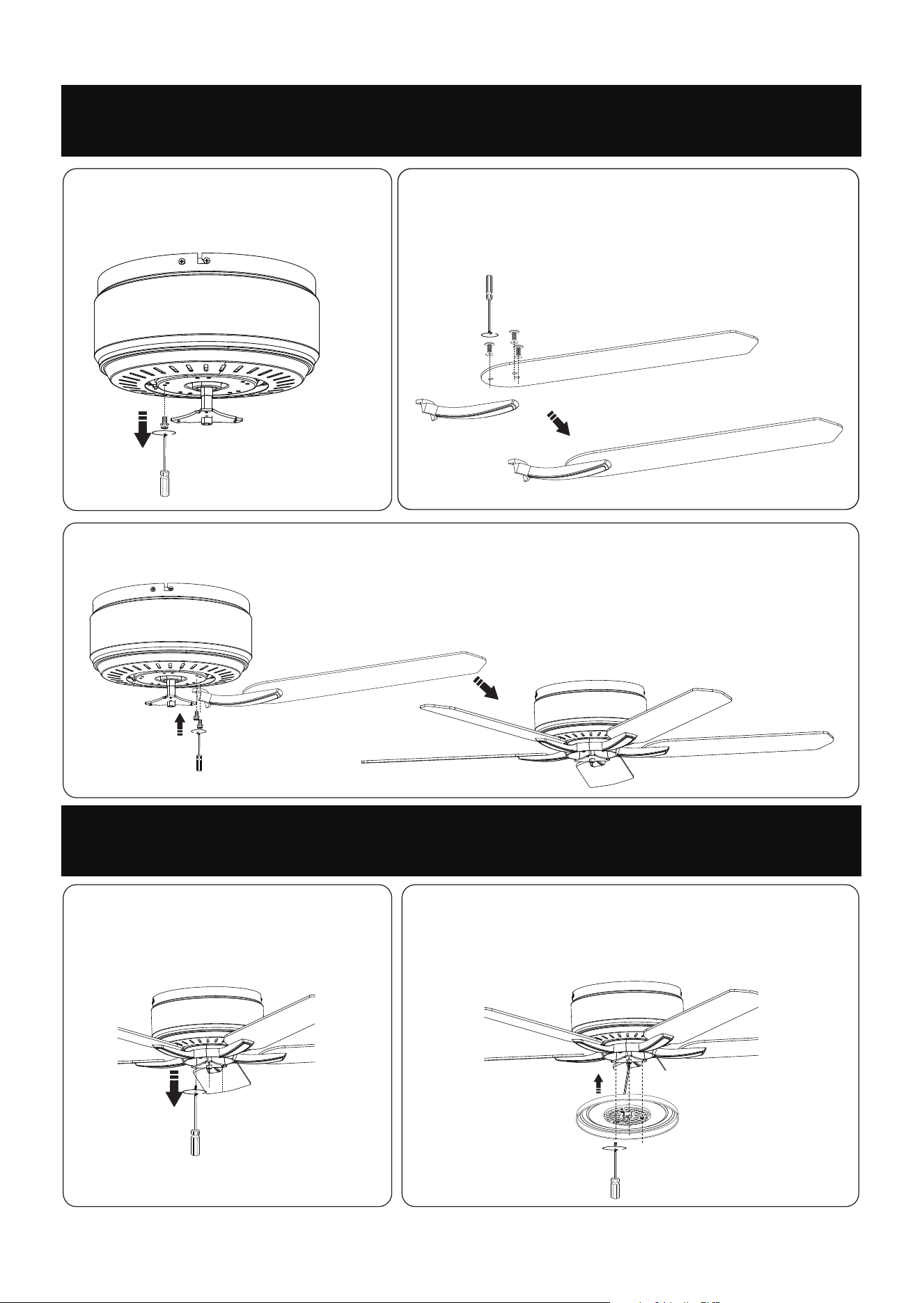
Step 1:
Remove 10 screws from the ceiling fan body,
place the screws for subsequent.
Attach the fan blade to the blade bracket using 3 blade
bracket screws and washers provided, tighten them
firmly. Complete 5 blades assembly.
Step 1: Step 2:
Remove 3 screws from motor assembly,
place the screws for subsequent.
Step 2:
Step 3:
Attach the blade assembly to the fan body using 2 removed screws and tigtem firmly. Install 5 blades.
Connect the wires of the fan motor assembly with light kit.
Attach the light kit to the fan motor assembly using 3 removed
screws and tighten firmly.
7
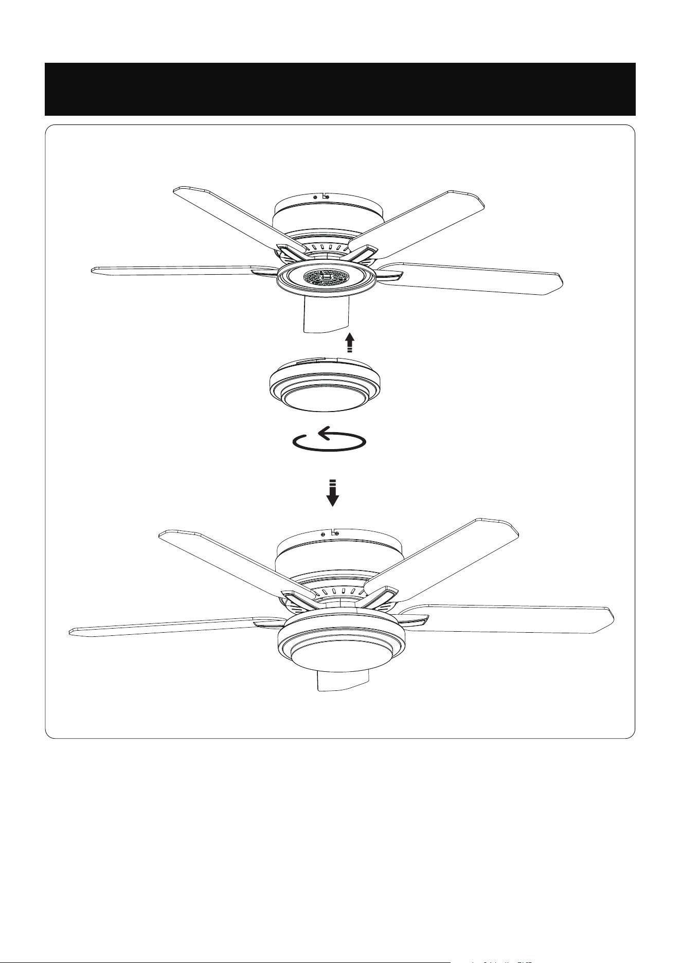
ASSEMBLING THE LIGHT SHADE
Rotate the light shade clockwise to securely fasten it into place.
8
PRODUCT SIZE
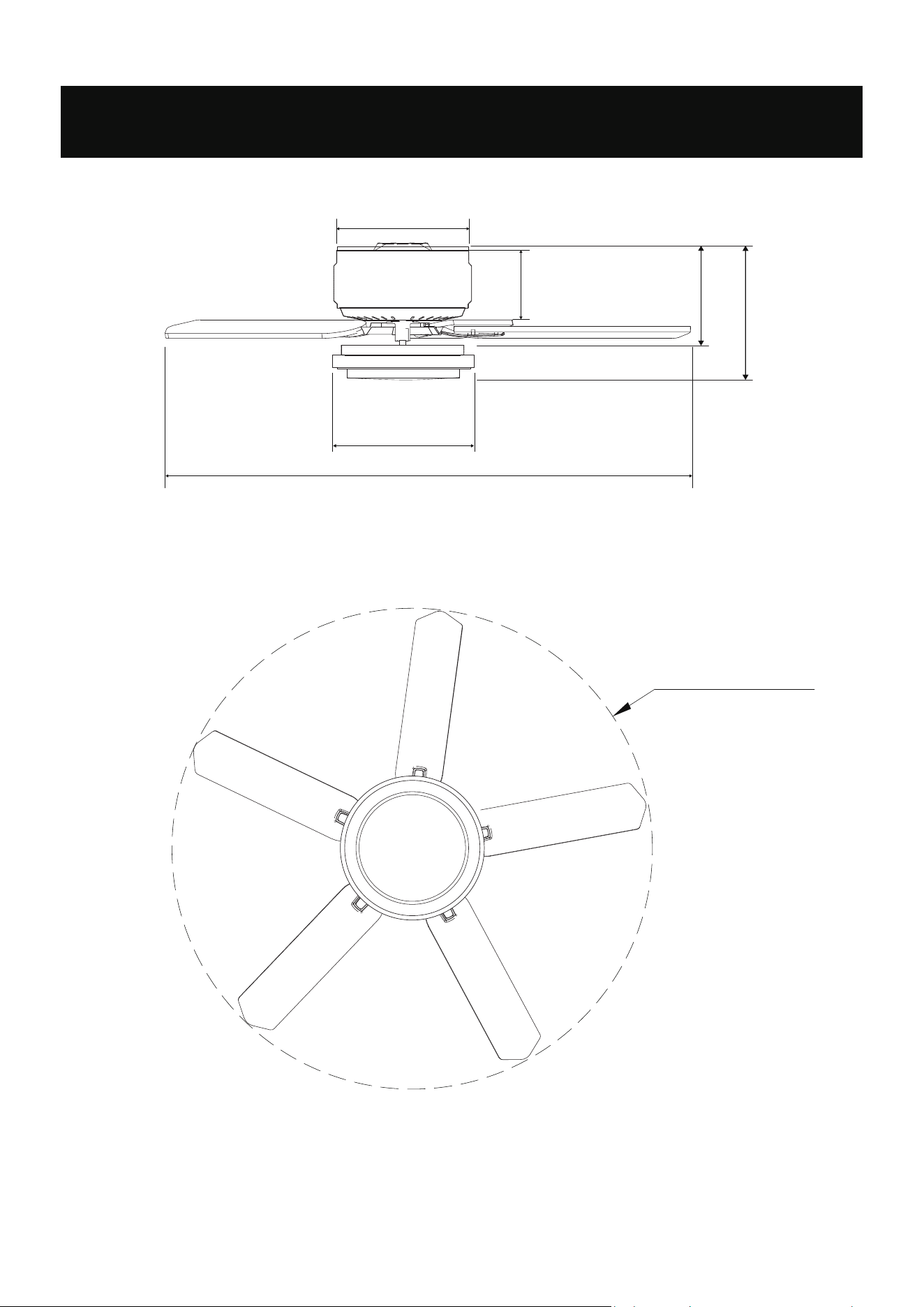
Dia 11.4 in. (Ø290mm)
Dia 11.4 in.
(Ø290mm)
52 in. (1320mm)
5.5 in.
(140mm)
10.6 in.
(270mm)
13.6 in. (345mm)
52 in. (1320mm)
9
REMOTE CONTROL OPERATION
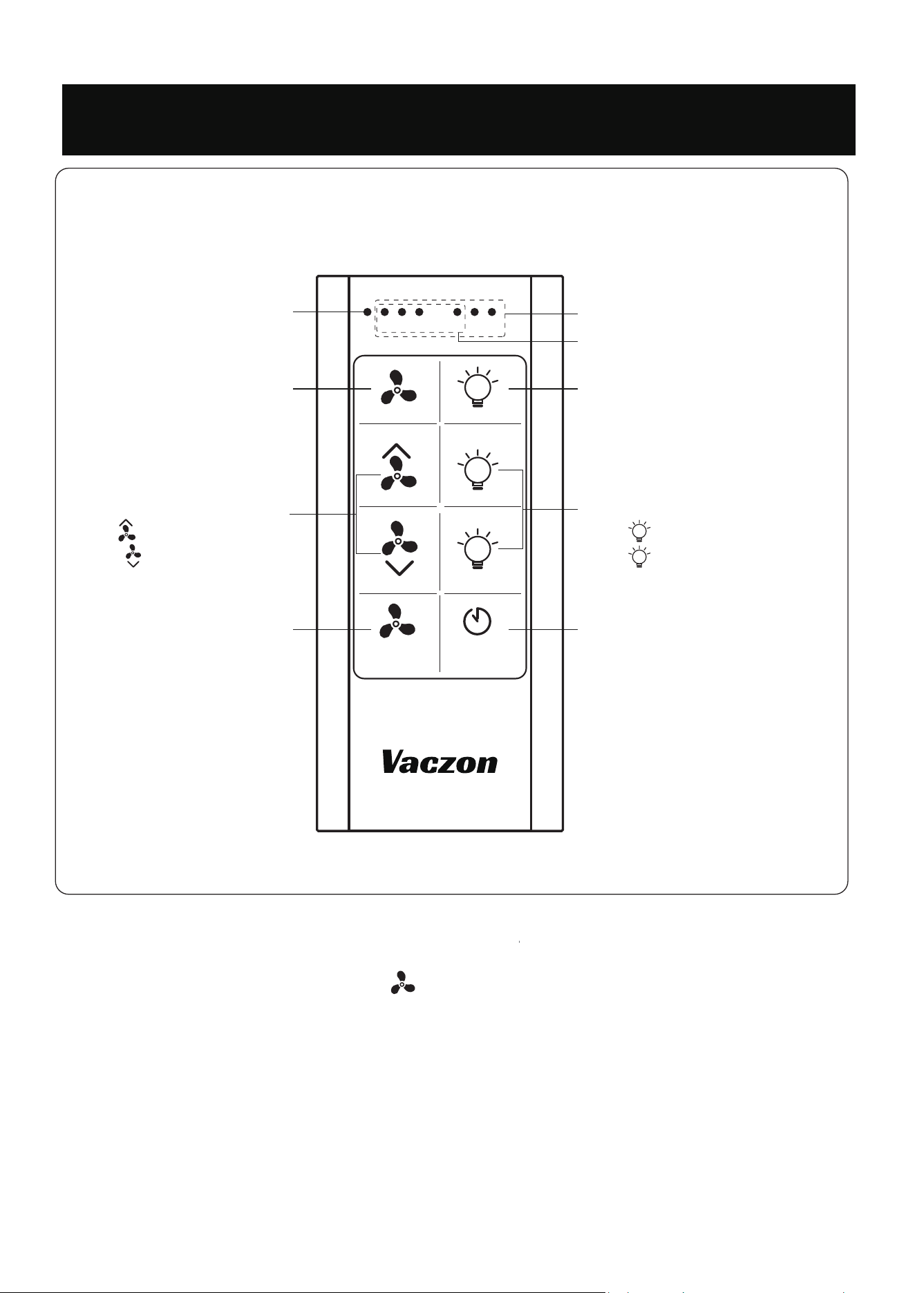
REMOTE CONTROL MATCHING CODE:
Within 5 seconds after power on, hold press the the key, when hear the buzzing sound, the code match is
successful. If not, please repeat the above steps again.
●
RF wireless digital transmission technology is adopted to realize the one-to-one control providing a rate of
coincident code less than 1/50000. Same code number is attached to the back of the emitter and the receiver.
It is required to return a pair of the same code number of emitter / receiver to the manufacturer for repair service in
case of any damage.
In a sufficient space, you can use the receiver at any angle, no worry about the direction.
●
Timer Settings
Control buttons
Power Switch
Press to turn the power ON/OFF
Within 5 seconds after power on,
hold press to match code.
Forward and Reverse
Press to change the airflow
direction.
Within 5 seconds after power on,
hold press to clear code.
Light Switch & CCT Setting
- Press to turn the light ON/OFF
- Hold press 2 seconds the key to change
the CCT to 3000K/4000K/6500K
- Press once time, fan auto off after 1hr
- Press twice time, fan auto off after 2hr
- Press 3 times, fan auto off after 4hr
- Press 4 times, fan auto off after 8hr
Fan Speed Setting
Fan CCT Setting
- Press key, light dimmer +
+
- Press key, light dimmer -
-
- Press key, fan speed 1 to 6 levels
- Press key, fan speed 6 to 1 level
LED Indicator
Time setting Indicator
Speed setting Indicator
REV
ON/OFF ON/OFF
1H/2H/4H/8H
K
+
-
1 2 4 8
10
REMOTE CONTROL OPERATION
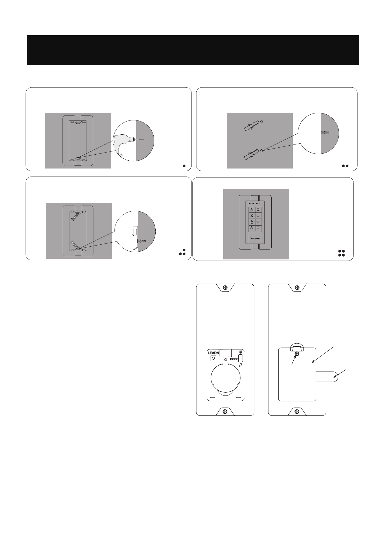
INSTALL THE REMOTE CONTROL HOLDER
Use the two holes on the holder as a guide to drill two
corresponding holes in the flat wall.
Insert two expansion screws into the holes and
make them level with the flat wall.
Align the two holes on the holder with the two holes
on the wall. Insert the two screws into the holes and
tighten them using a screwdriver.
NOTE: Install a CR2032, 3 volt lithium battery
(Included). Open battery cover to remove
insulation spacer before use remote control.
REPLACE THE BATTERIES
Remove the screw from the battery cover on the
remote control using a Phillips head screwdriver.
Pull up and remove battery cover.
Remove the old battery and replace a new
CR2032, 3V battery. Install the battery cover
removed earlier with the screw removed.
WARNING
TO REDUCE THE RISK OF SHOCK.THIS FAN MUST BE INSTALLED WITH A WALL CONTROL/SWITCH.
Battery cover
Insulation spacer
Screw
CR2032
3V lithium battery
Store your remote control.
K
+
-
1 2 4 8
REV
ON/OFF ON/OFF
1H/2H/4H/8H
11
This device complies with Part 15 of the FCC Rules. Operation is subject to the following two conditions:
(1) this device may not cause harmful interference.
(2) this device must accept any interference received, including interference that may cause undesired
operation.
Please note that changes or modifications of this product is not expressly approved by the party responsible
for compliance could void the user's authority to operate the equipment. NOTE: This equipment has been
tested and found to comply with the limits for a Class B digital device, pursuant to Part 15 of the FCC Rules.
These limits are designed to provide reasonable protection against harmful interference in a residential
installation. This equipment generates, uses and can radiate radio frequency energy and, if not installed
and used in accordance with the instructions, may cause harmful interference to radio communications.
However, there is no guarantee that interference will not occur in a particular installation.
If this equipment does cause harmful interference to radio or television reception which can be determined
by turning the equipment off and on, the user is encouraged to try to correct the interference by one or
more of the following measures:
-Reorient or relocate the receiving antenna.
-Increase the separation between the equipment and receiver.
-Connect the equipment into an outlet on a circuit different from that to which the
receiver is connected.
-Consult the dealer or an experienced radio/TV technician for help.
FCC STATEMENT
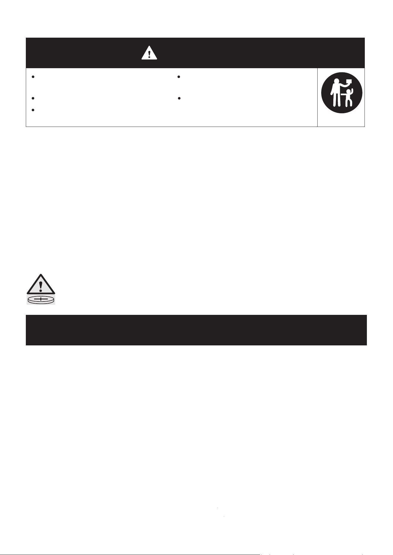
WARNING INGESTION HAZARD:
This product contains a button cell or coin battery.
Remove and immediately recycle or dispose of used batteries according to local regulations and keep away
from children. Do NOT dispose of batteries in household trash or incinerate.
Even used batteries may cause severe injury or death.
Call a local poison control center for treatment information.
Compatible battery type is CR2032, 3V.
Ensure the batteries are installed correctly with regard to polarity (+ and -).
Do not mix old and new batteries, different brands or types of batteries, such as alkaline, carbon-zinc,
or rechargeable batteries.
Non-rechargeable batteries are not to be recharged. Exhausted batteries are to be removed from the
product.
Do not force discharge, recharge, disassemble, heat above (manufacturer's specified temperature rating)
or incinerate.
Doing so may result in injury due to venting, leakage or explosion resulting in chemical burns.
Remove and immediately recycle or dispose of batteries from equipment not used for an extended period
of time according to local regulations.
Always completely secure the battery compartment. If the battery compartment does not close securely,
stop using the product, remove the batteries, and keep them away from children.
WARNING
INGESTION HAZARD:
This product contains a
button cell or coin battery.
DEATH
or serious injury can occur if ingested.
A swallowed button cell or coin battery can cause
Internal Chemical Burns
in as little as 2 hours.
KEEP
new and used batteries
OUT OF BEACH OF CHILDREN
Seek immediate medical attention
if a
battery is suspected to be swallowed or inserted
inside any part of the body.
12
APP OPERATION
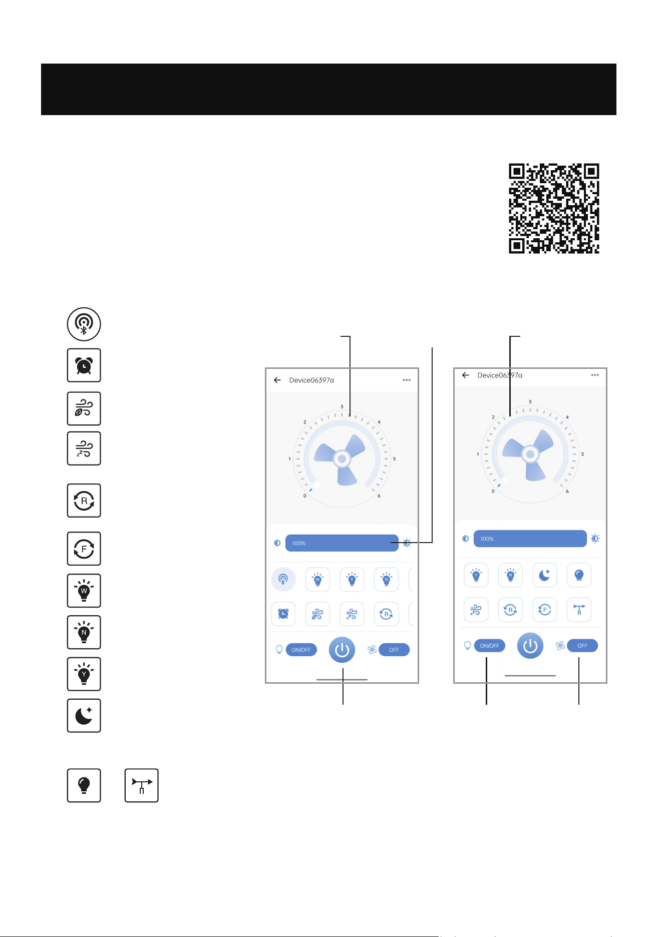
Step 1: Scan QR code, or Search "eWeLink" from App Store or Google Play to download the app.
Step 2: Turn on the Bluetooth.
Step 3:
Step 4: Pair code with the app.
a. Click the buttons within 5 seconds when the light turn on, if the light
flicks/when you hear a beep, it means the fan and app successfully
paired. (APP Control Distance: within 65ft (20m))
b. The previous phone will jump out automa-tically if the next phone is
paired successfully.
Add device, name the fan light, and choose the room for your fan.
APP button function description:
Pairing Button
Timer Setting Mode
Natural Wind Mode
Sleep Wind Mode
The fan rotates in reverse
to distribute warm air
throughout a room.
The fan rotates forward.
White light
Yellow light
Natural light
Night light,10% bightness.
Light Switch
Power Switch
Fan Switch
Adjust Fan Speed Adjust Light Brightness
Adjust Light CCT
Not apply to these function follow:
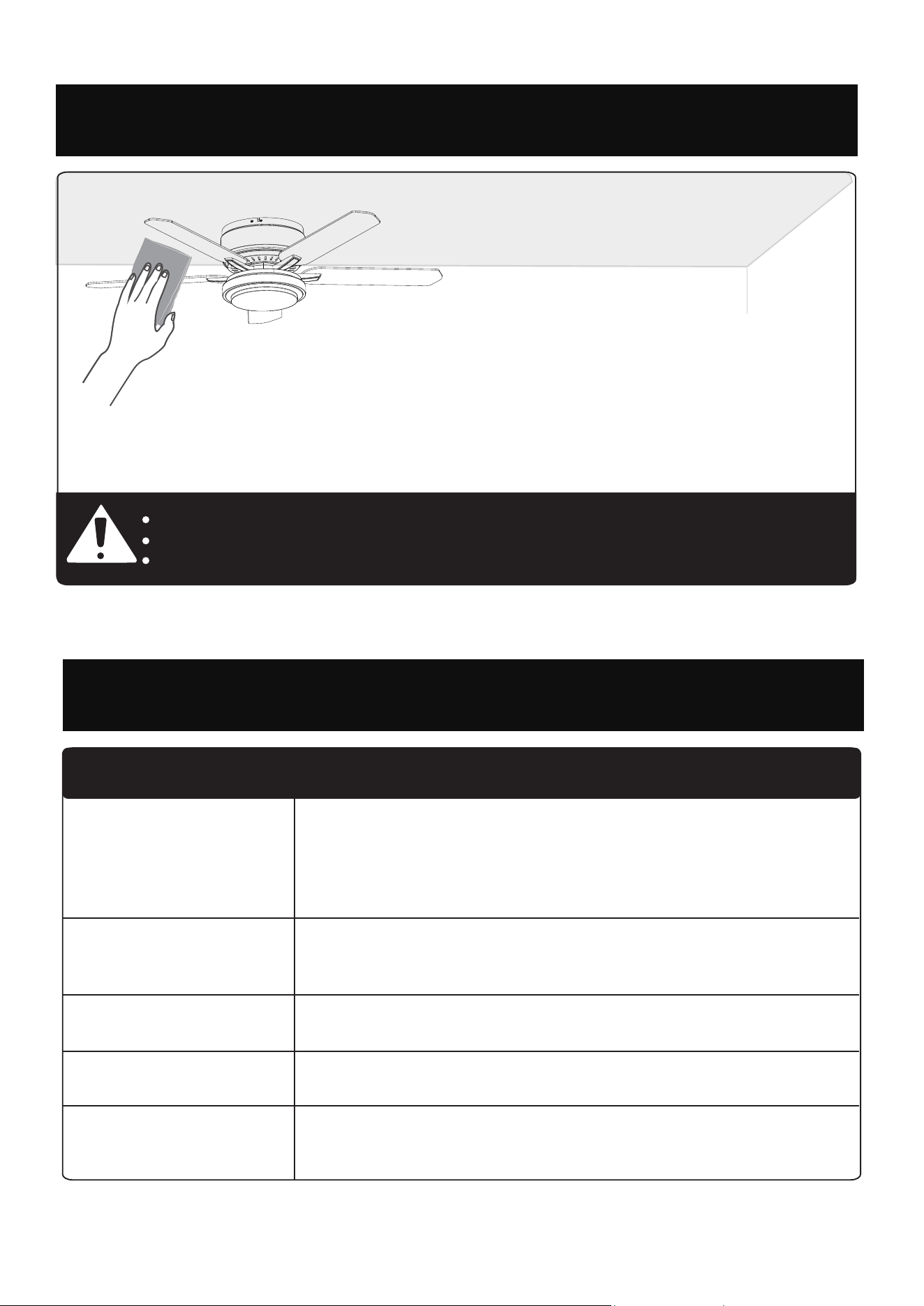
Clean the motor housing and blades
with a soft brush or lint-free cloth to
avoid scratching the finish.
At least twice each year, check the
ceiling bracket assembly and tighten
all screws on the fan.
Shut off the main power supply before you begin any maintenance task.
DO NOT use water or a damp cloth to clean the fan.
Cleaning products may damage the finishes.
CLEANING AND MAINTENANCE
13
Problem
Solution
Fan Doesn't Work
· Make sure the power switch is on.
· Check the circuit breaker to ensure the power is turned on.
· Make sure the blades spin freely.
· Turn off power from the circuit breaker, then loosen the canopy and
check all the connections according to the wiring diagram
Excessive Wobbling
· Make sure the blades are properly installed on the ceiling fan body.
· Turn the power off, support the fan carefuly, and check that the downrod
ball is properly seated.
Remote Control of
Fan is Erratic
· Make sure the battery is installed correctly. lf the command indicator
light keeps flashing, indicating low battery, install a fresh battery.
Remote Only Works
Close to Fan
· Change battery
Noisy Operation
· Make sure the blades are properly installed.
· Check to see if any of the blades are cracked. lf so, replace all of the
blades
If your problem is not listed or still persists, please contact our Customer Support.
TROUBLESHOOTING

We’re Here to Help!
1 (888) 275-3352
Customersupport@Vaczon.com
https://vaczon.com