F8322110V
READ AND SAVE THESE INSTRUCTIONS
INSTALLATION MANUAL
English
F8322110V
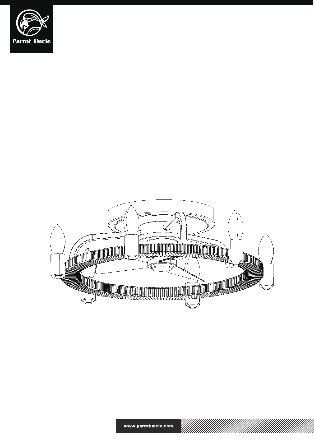
110-120VAC 6*E12 Bulb MAX. 5W
(not included)
5W±0.5W
F8322110V
Installation & Operating Instructions for the
Parrotuncle Owner's Installation, Manual
WARNING: SHUT POWER OFF AT FUSE OR CIRCUIT BERAKER
SKU# Rated Voltage Rated Power (motor) Light
WARNING: To reduce the risk of personal injury,
do not bend the blade brackets (also referred to as
flanges) during assembly or after installation. Do not
insert objects in the path of the blades.
WARNING: To reduce the risk or fire or electric
shock, do not use this fan with any solid-state
speed control device.
WARNING: To avoid possible electric shock,
turn the electricity off at the main fuse box before
wiring. If you feel you do not have enough electrical
wiring knowledge or experience, contact a licensed
electrician.
WARNING: Electrical diagrams are for reference
only. Optional use of any light kit shall be UL-listed
and marked suitable for use with this fan.
WARNING: To reduce the risk or fire, electric shock,
or personal injury, mount to outlet box marked”
Acceptable for fan support of 35 lbs.(15.9 kg) or
less“ and use the screws provided with the outlet
box.
WARNING: Remove the rubber motor stops on
the bottom of the fan before installing the blades
or testing the motor.
Safety Information
To reduce the risk of electric shock, the electricity
has been turned off at the circuit breaker or fuse
box before begin.
All wiring must be in accordance with the National Electrical
Code NASI/NFPA 70-1999 and local electrical codes.
Electrical installation should be performed by a qualified
licensed electriccian.
The outlet box and support structure must be securely
mounted and capable of reliably supporting
35lbs(15.9kg). Use only UL listed outlet boxes marked
“Acceptable for Fan Support of 35lbs(15.9kg) or less.”
The fan must be mounted with a minimum of 7 ft. (2.1m)
clearance from the trailing edge of the blades to the floor.
Do not operate the reversing switch while the fan blades
are in motion. You must turn the fan off and stop the
blades before you reverse the blade direction.
Do not place objects in the path of the blades.
To avoid personal injury or damage to the fan and
other items, please be careful when working around
or cleaning the fan.
Electrical diagrams are for reference only. Light kits that
are not packed with the fan must be UL-listed and marked
suitable for use with the model fan you are installing.
Switches must be UL General Use Switches. Refer to the
instructions packaged with the light kits and switches for
proper assembly.
After making electrical connections, spliced conductors
should be turned upward and pushed carefully up into
the outlet box. The wires should be spread apart with the
grounded conductor and the equipment-grounding
conductor on one side of the outlet box.
All set screws must be checked and retightened where
necessary before installation.
1.
2.
3.
4.
5.
6.
7.
8.
9.
10.
F8322110V
Installation & Operating Instructions for the
Parrotuncle Owner's Installation, Manual
WARNING: SHUT POWER OFF AT FUSE OR CIRCUIT BERAKER
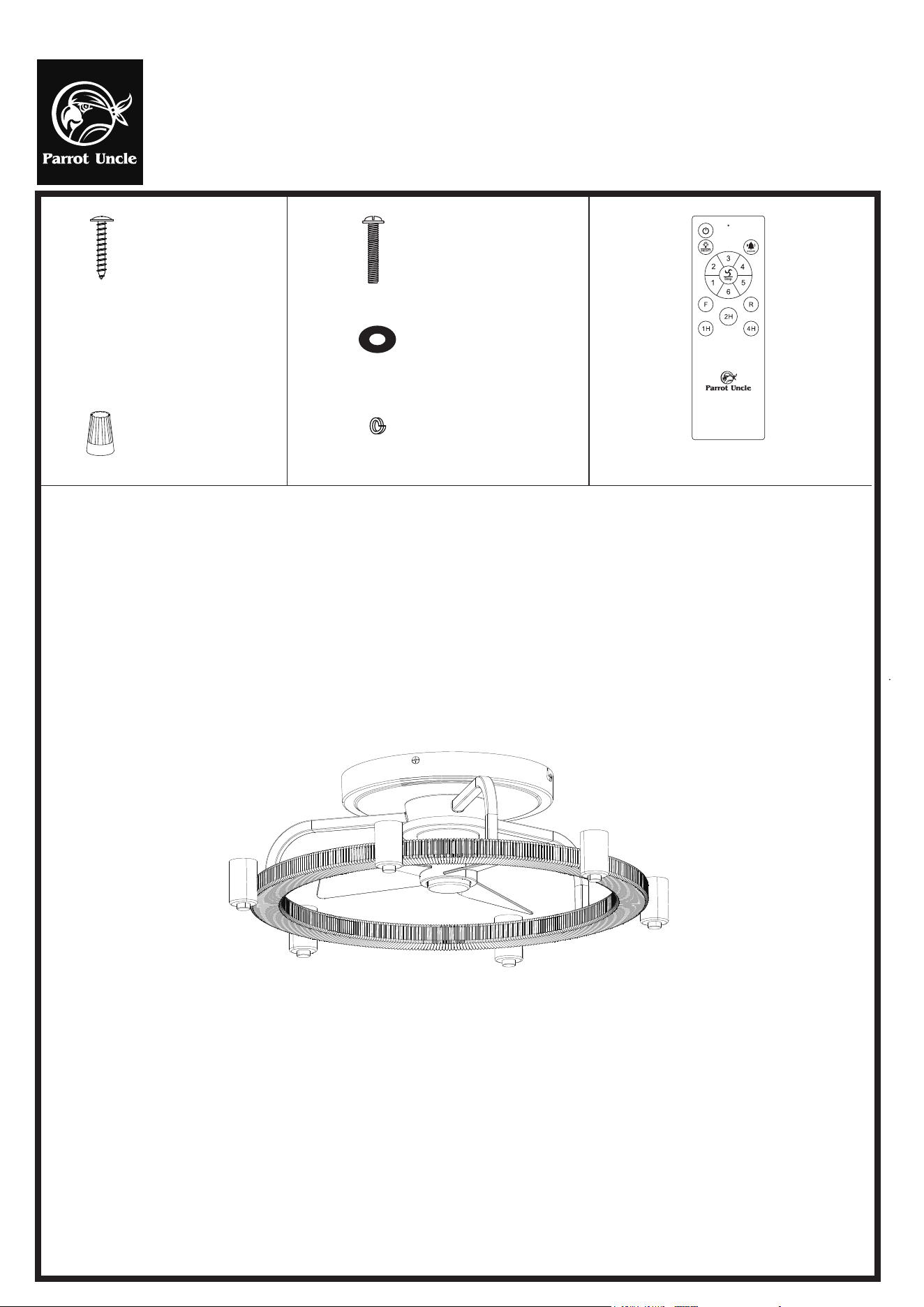
Wood screws
(4PCS)
Plastic wire nut
(3PCS)
Mounting screws
(2PCS)
Washer (2PCS)
Spring washer
(2PCS)
Remote control (1PC)
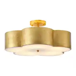
Light fixture (1PC)
PIs check whether above accessories are completed or not? Yes, and install.
F8322110V
Installation & Operating Instructions for the
Parrotuncle Owner's Installation, Manual
WARNING: SHUT POWER OFF AT FUSE OR CIRCUIT BERAKER
1
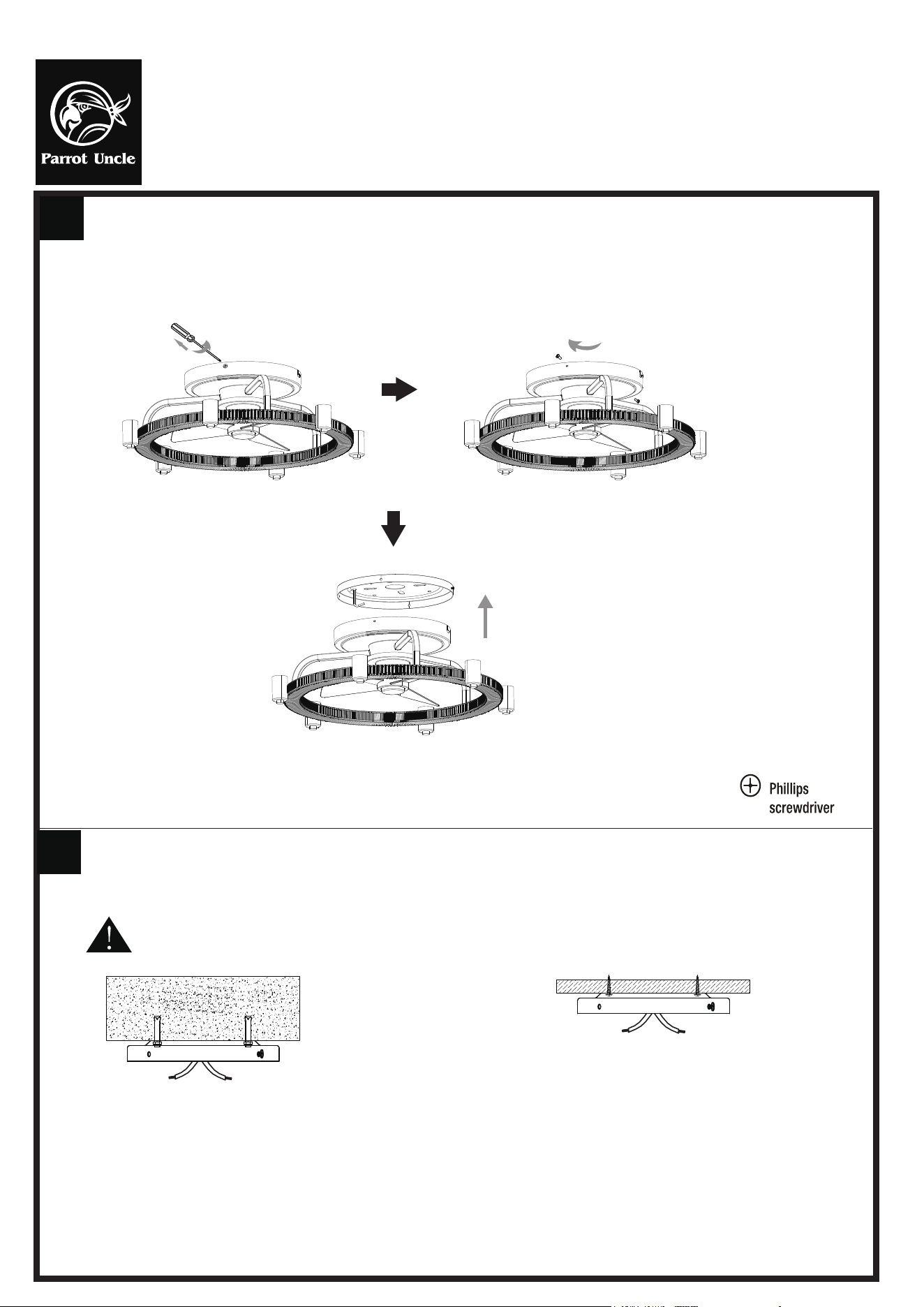
INSTALLING THE HANGING PLATE:
Install the hanging plate to the ceiling and thread the power supply through the center hole of the hanging plate.
REMOVE THE HANGING PLATE FROM THE LIGHTING FIXTURE:
1. Remove 2 screws from the lighting fixture
2. Loose 2 screws from the hanging plate
3. Rotate the hanging plate counterclockwise and remove it from the light fixture
2
Note: Turn off the power before installation
(1) Cement ceilings use expansion
screws (not included).
(2) Wooden ceilings use wood screws.
F8322110V
Installation & Operating Instructions for the
Parrotuncle Owner's Installation, Manual
WARNING: SHUT POWER OFF AT FUSE OR CIRCUIT BERAKER
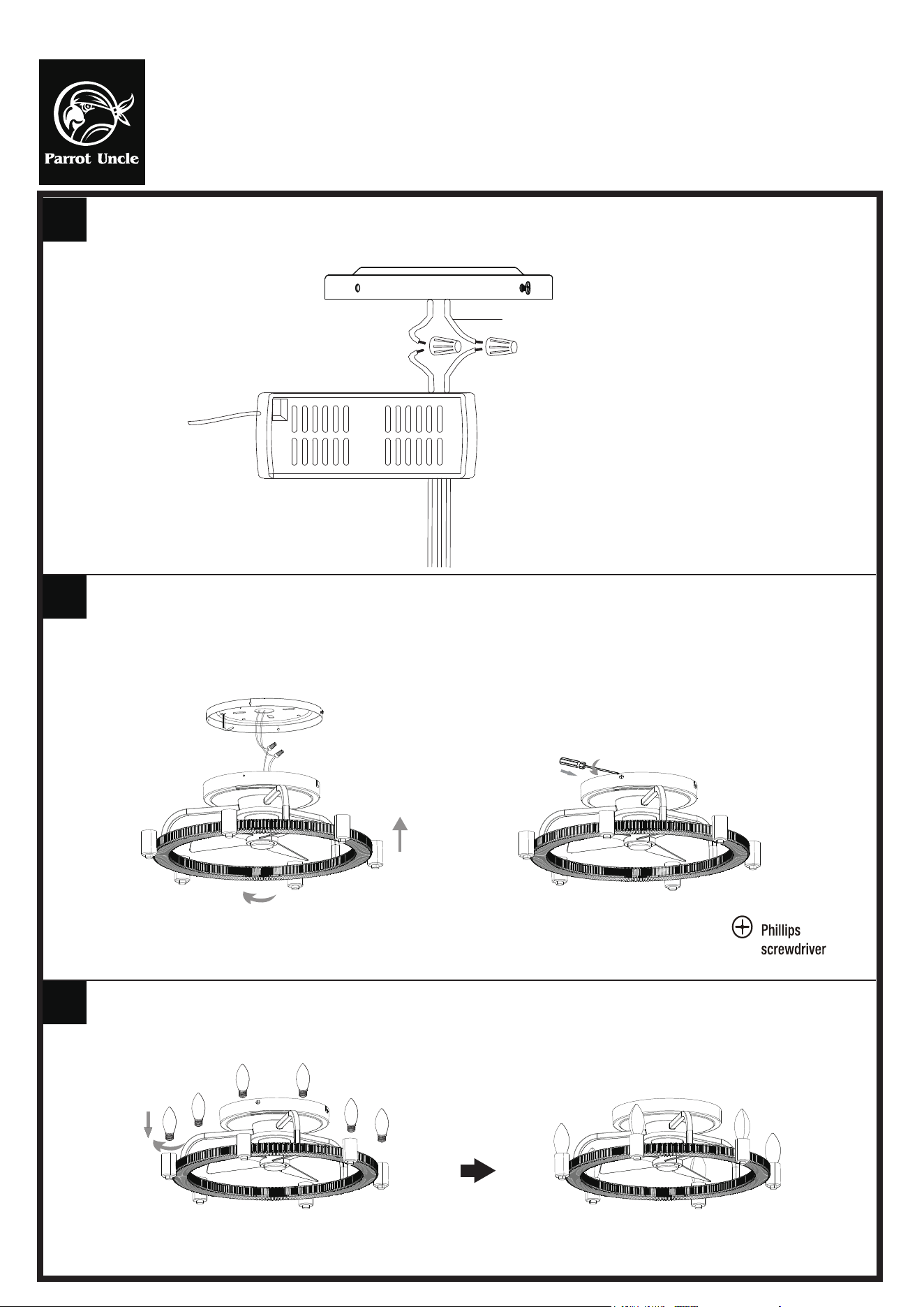
CONNECT WIRE:
Connect the remote controller ( pre-installed in the canopy of the lighting fixture) to the power supply using plastic wire nuts.
3
INSTALLING THE LIGHT FIXTURE TO HANGING PLATE:
1. Locate 2 screws of the hanging plate, attach light fixture to the hanging plate by placing screws into the keyhole slots.
Rotate the light fixture counterclockwise so that screws slide into the narrow ends of the slots.
2. Use the 2 screws that were previously removed to lock the light fixture and the hanging plate tightly.
3. Tighten the all screws firmly.
4
INSTALL 6 E12 BULBS
(not included)
.
5
Power source 110~120 vac 60Hz
WHITE
INPUT
RED/BLACK
OUTPUT
ANT
F8322110V
Installation & Operating Instructions for the
Parrotuncle Owner's Installation, Manual
WARNING: SHUT POWER OFF AT FUSE OR CIRCUIT BERAKER
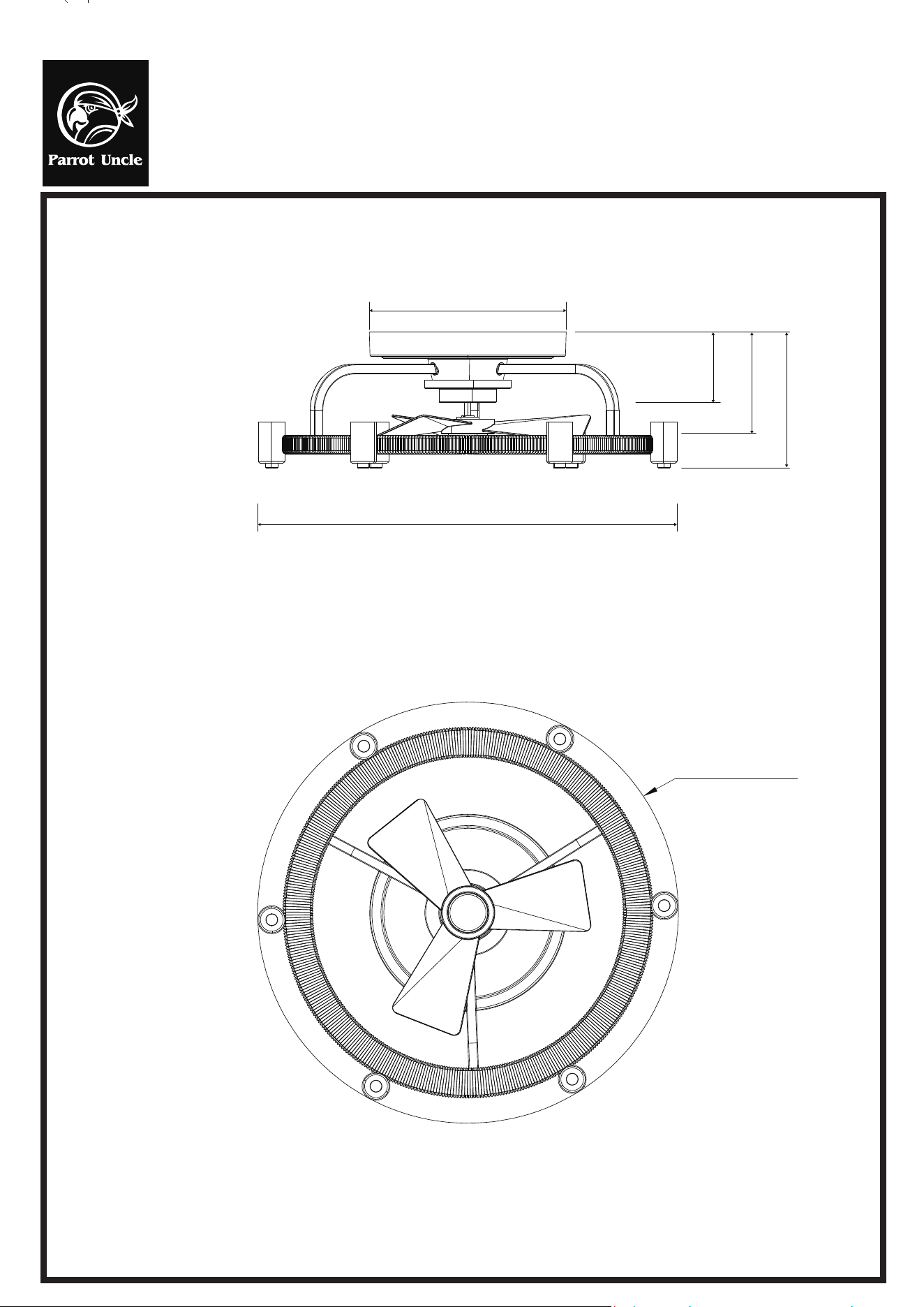
PRODUCT SIZE
Dia 20.3 in. (Ø517mm)
Dia 9.5 in. (Ø242mm)
3.4 in.
(87mm)
4.9 in. (125mm)
6.5 in. (166mm)
Dia 20.3 in. (
Ø
517mm)
F8322110V
Installation & Operating Instructions for the
Parrotuncle Owner's Installation, Manual
WARNING: SHUT POWER OFF AT FUSE OR CIRCUIT BERAKER
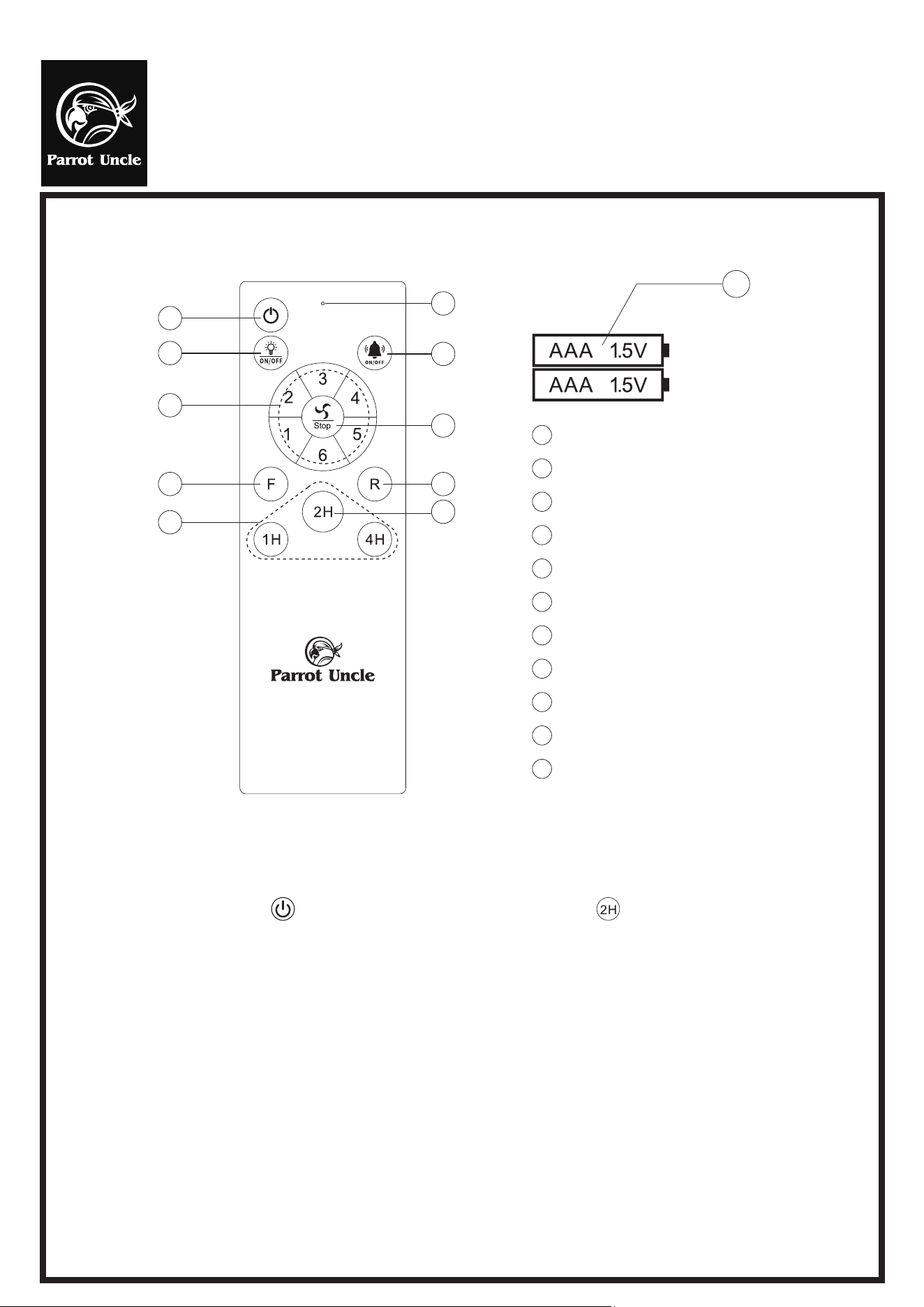
11
Actual use shall be subject to the real product
Remote control matching code:
NOTICES
1. When the emitter is unable to remotely control the receiver, please check whether the switch batteries are in good contact, whether
they are fixed properly and whether they run out of use.
2. When the emitter is unable to remotely control the receiver, please check whether there is other remote control products around the
space and check whether the keys are pressed down, because same nature of remote control product may cause interference with
each other resulting in poor receiving effect. Taking away such articles will normalize the remote control function. (the infrared
remote controller is not included).
3. Please use this product under applicable voltage. Too low voltage will lead to failure of the remote controller to work (Please refer to
the product label for the voltage range and related parameters).
4. Please take out the batteries if you will no use this product for a long time.
●
●
RF wireless digital transmission technology is adopted to realize the one-to-one control providing a rate of
coincident code less than 1/50000. Same code number is attached to the back of the emitter and the receiver.
It is required to return a pair of the same code number of emitter / receiver to the manufacturer for repair service in
case of any damage.
In a sufficient space, you can use the receiver at any angle, no worry about the direction.
1
4
5
6
8
10
2
3
7
9
1
Power Switch
2
Light Switch
4 Switch Indicator
5
Sound Switch
6
Fan Power OFF
7 Forward Rotation
8
Reversal
9 Timer
10
Code matching
11 2 X1.5V AAA Battery
3 Speed Controller
2.4G Fan Light Controller
This product uses 2.4G wireless digital remote control technology, remote control one-to-one control, simple and
convenient operation, strong anti-interference ability.
Turn on the power
(
press the key
)
and press and hold the code matching key within 5 seconds of the light
on, when you hear a beep or a light flashes, the code match is successful. If you need to match the code a second
time, you need to wait 30 seconds before turn on the power and repeat the above operation.
F8322110V
Installation & Operating Instructions for the
Parrotuncle Owner's Installation, Manual
WARNING: SHUT POWER OFF AT FUSE OR CIRCUIT BERAKER
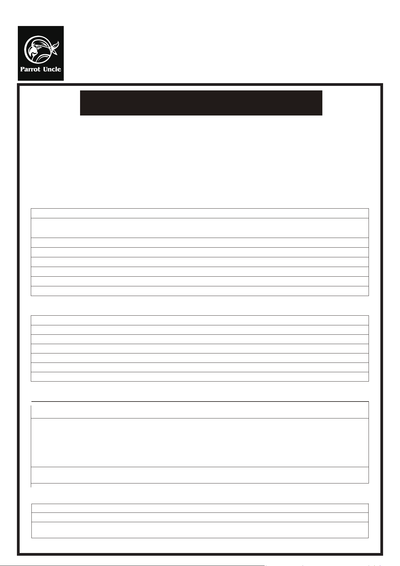
TROUBLESHOOTING GUIDE
Table of Contents
1. Fan / Remote is not working
2. Fan is noisy
3. Fan Wobbles
4. Light is not working
Please refer to the instruction sheet for detailed directions and descriptions of
installation steps and requirements
1. FAN / REMOTE IS NOT WORKING
Ensure the remote is within the 20 feet range of the receiver
To reset the remote control: 1) Turn off power to fan using the wall switch or circuit breaker. 2) Remove ba�eries from remote.
3) Wait 10 seconds. 4) Replace ba�eries and turn power on
Check ba�eries to insure they are good and oriented correctly
Check to make sure the frequency switches (DIP Switches) from the remote to the receiver are set to the same frequency
Check the main and branch circuit fuses or breakers
If using a Variable Speed Wall Switch, ensure it is specifically designed for use with a ceiling fan.
Check the line wire connec�ons to the fan and the switch wire connec�ons in the switch housing per the instruc�ons
If fan s�ll does not work, please contact Customer Service [email protected]
Make sure all motor housing screws are �ghtened
Make sure the screws that a�ach fan blade to motor are �ght
Make sure the wire nut connectors are not ra�ling against each other or the interior wall of the switch housing
Allow 24-hour break in period. Most noises associated with the new fan may disappear during this �me
If using a ceiling light kit, make sure the glassware is secured �ghtly
Make sure there is a short distance/gap from the ceiling to the top of the canopy. The canopy should not touch the ceiling!
Make sure your ceiling box is secure and that the rubber isolator pads are used between the moun�ng bracket and outlet box
2. THE FAN IS NOISY
Verify all blades and blade bracket screws are secure (most fan wobble problems are caused by loose parts). Once fan is properly
installed, run the ceiling fan for 10 minutes to let the fan self-adjust.
If wobble occurs a�er running the fan for 10 minutes, verify blade level using the following process:
a) select a point on the ceiling above the �p of one of the blades. Then select the fan blade and measure from the center
of the selected blade to point on the ceiling. Rotate the fan un�l the next blade is posi�oned and repeat the
measurement using the same point from the ceiling for every blade. Measurements should be within 1/8 inch.
3. THE FAN WOBBLES
b) If all devia�on are less than 1/8 inch and the fan con�nues to wobble, please contact Customer Service Support@parr
otuncle.com to order a complimentary Blade Balancing Kit
- If all devia�ons are less than 1/8 inch and the fan con�nues to wobble, please contact Customer Service Support@parrotuncle
.com to order a complimentary Blade Balancing Kit
4. LIGHT IS NOT WORKING
Check Bulb to make sure it is installed correctly
Remove non-working bulb and replace with a bulb that is known to be a good working bulb
To reset the remote control: 1) Turn off power to fan using the wall switch or circuit breaker. 2) Remove ba�eries from
remote. 3) Wait 10 seconds. 4) Replace ba�eries and turn power on