1. Preparations Before Installation
2. [Central Console,Footlight ] Main Module Installation
3. [Door Panel] Sub Module Installation
1. If you encounter any problems during installation, please remove the kit and connect directly to
the car battery, and test again.
2. If the ambient light returns to normal operation, it is judged to be caused by installation error.
3. On the contrary, if the ambient light still cannot work normally, it is judged as a product fault and
can apply for after-sales service.
4 . All products are not guaranteed by wire cutting.
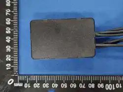
Distinguish the main module and sub module
1. Module with QR Code is the main control,
Function: Signal Projector, synchronously control all sub modules
2. Rest are sub module;
Function: Signal receiver, receive main module instructions, synchronous color change;
3. The main module must be powered on, then sub module will light up
4. Scan the QR code to download the APP, no need to select the pairing code, turn on bluetooth
and it will connect automatically (note Android system needs turn on position function)
Test the product
After receiving the product, connect the battery of the car (do not use external power supply) If no
problem, We can starts the installation
The power connection mode of the Main Module and the Sub Module
1. Positive pole: connect ACC 10-15A Fuse (recommend to add 5A from the original fuse current),
pay attention to avoid the sensor interface
2. Negative pole: connect the car body cast iron/negative pole
3. Attn:Automatic headlights, Console GPS, DVD Wiring not available
(INPUT: 6-18V OUT PUT: 3V/5V)
(INPUT: 6-18V OUT PUT: 3V/5V)
Test the power supply of Door Panel:
ACC Power or Constant Power?
NOTE: normally Germeny car is constant power, Janpanese& Korean car is Acc power.
Test Method 1: When the car flameout, if the door has a automatic window closed function, the
door is constant power
Test Method 2: Press the shortcut key to start the car, without igniting the car, if the window lifter
can move rise and fall, the door is constant power
Test Method: If the door functuion not available until the car ignited, the door is ACC power.
The door is ACC power:
Normally the door of Japanese and Korean car is ACC power.
1. MUST Igniting the car before test possitive& negative pole (the door of ACC power supply, do not
ignore this step )
2. Find out the positive pole, Votage 6-18V available, choose the thick wire
3. Find out the negative pole (negative Power from door iron or screws isforbidden)
4. Connect sub-control module with the founded power supply, turn the window lifter, and check
whether the ambient light works normal when window up and down. (Do not restore the door at the
moment, turn the light to white color mode and keep testing for about 5 minutes)
5. If the ambient light goes off or flashes when the window is lifted, it means the power supply is
unstable, please find workable positive wires again.
The door is constant power:
Normally Germeny car is constant power
1. Igniting the car before test possitive& negative pole (the door of constant power supply, also
recommend this step)
2. Find out the positive pole, Votage 6 - 18V available, choose the thickwire.
3. Find out the negative pole (negative Power from door iron or screws isforbidden)
4. Connect sub-control module with the founded power supply, turn the window lifter, and check
whether the ambient light works normal when window up and down. (Do not restore the door at the
moment, turn the light to white color mode and keep testing for about 5 minutes)
5. If the ambient light flashes when the window is lifted, it means the power supply is unstable. If the
ambient light goes off, must first determine the positive or negative pole problem and find workable
positive wires again.
Light strip installation steps
1. Remove the trim panel of the center console, thread the light strip wires through the holes of the
trim panel and connect to the main module.
2. Secure the light strip to the trim board with 3M tape and cut off excess strip.
3. Install the trim panel along with the light strip on the centerconsole.
Four sub module are installed on each of the four doors
1. Remove the door panel.
2. Remove the screws of the door trim panel and remove the trim panel.
3. The acrylic light strip runs from the back of the door panel through the hole in the trim panel to the
front of the door panel.
4. Fasten the light strip to the decorative board with 3m tape.
5. Install the trim panel along with the light strip to the door panel.
6. Connect the light strip wires on the back of the door panel to the sub module.
7. Install the door panel
1. After the whole vehicle is installed, turn all the lights of the whole vehicle to white color mode and
keep testing for about 5-10 minutes.
2. Move the window lift to observe whether the ambient light goes off orflashes.
3. Make sure there is no problem and load the door back.
This device complies with Part 15 of the FCC Rules. Operation is subject to the following two
conditions:
(1) This device may not cause harmful interference, and (2) this device must accept any interference
received, including interference that may cause undesired operation.
NOTE 1: This equipment has been tested and found to comply with the limits for a Class B digital
device, pursuant to part 15 of the FCC Rules. These limits are designed to provide reasonable
protection against harmful interference in a residential installation. This equipment generates, uses
and can radiate radio frequency energy and, if not installed and used in accordance with the
instructions, may cause harmful interference to radio communications. However, there is no
guarantee that interference will not occur in a particular installation. If this equipment does cause
harmful interference to radio or television reception, which can be determined by turning the
equipment off and on, the user is encouraged to try to correct the interference by one or more of the
following measures:
- Reorient or relocate the receiving antenna.
- Increase the separation between the equipment and receiver.
-Connect the equipment into an outlet on a circuit different from that to which the receiver is
connected.
-Consult the dealer or an experienced radio/TV technician for help.
NOTE 2: Any changes or modifications to this unit not expressly approved by the party responsible
for compliance could void the user's authority to operate the equipment.
RF Exposure Statement
To maintain compliance with FCC'S RF Exposure guidelines, This equipment should be installed
and operated with minimum 20cm between the radiator and your body. This device and its
antenna(s) must not be co-located or operation in conjunction with any other antenna or transmitter.
.