1
OPERATING MANUAL
SMART SWITCH
2
Smart Switch is a Z-Wave Switch module specifically used to enable Z-Wave
command and control(on/off)of any plug-in tool. It can report wattage consumption or
kWh energy usage.
Smart Switch is also a security Z-Wave device and supports the Over The
Air(OTA)feature for the product's firmware upgrade.
The features list:
(1)Supports 1xAC output;
(2)AC output switch on/off by manual or Z-Wave command;
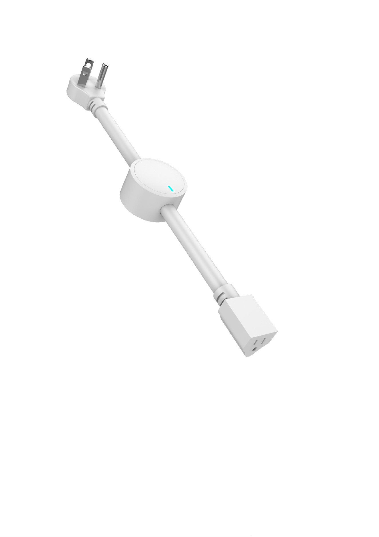
(3)RGB LED indicates the Z-WAVE network range;
(4)RGB LED indicates the load power;
(5)Z-Wave plus compatible (800 serials product);
(6)Supporting power meter;
(7)Supporting firmware OTA;
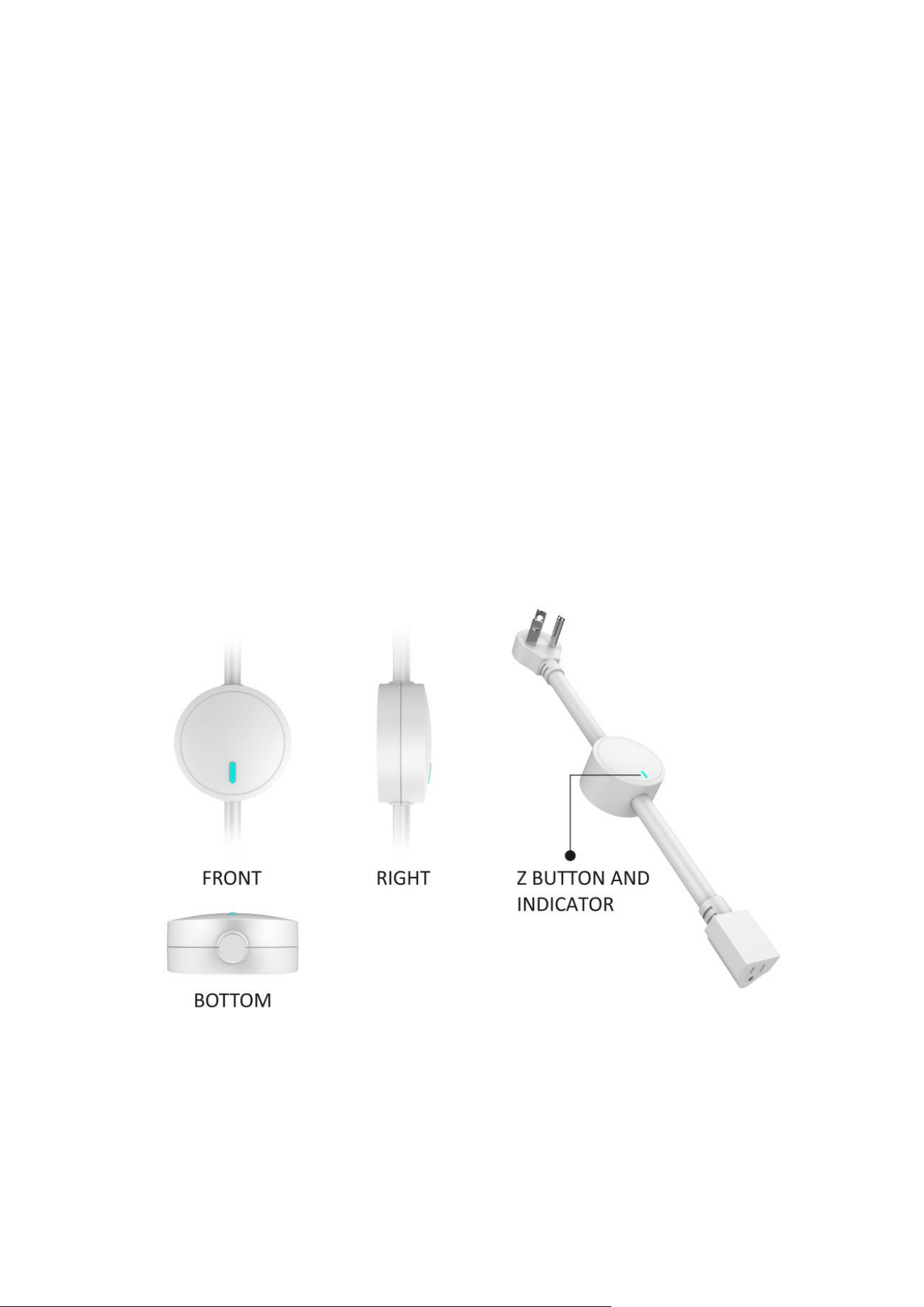
I.GENERAL INFORMATION ABOUT SMART SWITCH
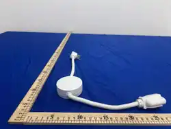
1.Product layout

3
2. Specifications
Power supply:
90~135VAC,60Hz
Rated load current:
15A MAX
Power consumption:
≤1.5W
Power output
(plug for resistive load):
1800W(120VAC)
Storage environment:
-20℃~60℃, 0%~80%
Operational temperature:
-10℃~40℃
Radio protocol:
Z-Wave Plus V2
Range:
More than 150m outdoors
About 40m indoors(depending on building materials)
Dimensions:
500mm(L)*65mm(W)*27mm(H)
Ⅱ.INSTALLATION
(1)Power on the Switch.
(2)Add device into your Z-Wave network if necessary
(3)Connect load to the device.
(4)Set the connected device to ON if necessary.
(5)Click Z-Button to turn off the switch manually.
Ⅲ.Z-WAVE NETWORK INCLUSION
Smart Switch can be included and operated in any Z-Wave network with other
Z-Wave certified devices from other manufacturers and/or other applications.
All non-battery operated nodes within the network will act as repeaters regardless of
vendor to increase reliability of the network.
Included as Z-Wave device
Smart Switch can be included into the Z-Wave network manually via the Z-Button. In
addition, the Smart Switch may be included in auto inclusion mode, by simply
connecting the power supply.
To include the Smart Switch into a Z-Wave network please complete following tasks:
Automatic Z-Wave network inclusion:
(1)Set the Z-Wave network main controller into inclusion mode(see Z-Wave network
controller operating manual).
(2)Power on the Switch.
(3)Auto-inclusion will be activated, Switch automatically starts looking for Z-Wave
network controller.Auto-inclusion activation is signaled by a single,RGB LED
indicator blink fast in blue.
(4)Smart Switch should be recognized and automatically included into the Z-Wave
network.

4
Manual Z-Wave network inclusion:
(1)Connect the power supply.
(2)Set the Z-Wave network main controller into inclusion mode(see Z-Wave network
controller operating manual).
(3)Triple click the Z-button,RGB LED indicator should blink fast in blue.
(4)Smart Switch should be recognized and included into the Z-Wave network.
IV.REMOVING FROM Z-WAVE NETWORK
To remove Smart Switch from the Z-Wave network:
(1)Insert the Plug into a socket.
(2)Set the Z-Wave network controller into the exclusion mode(see Z-Wave controller
operating manual).
(3)Triple click the Z button.
(4)RGB LED indicator will blink orange till the removing process is completed,than
the indicator will keep orange for 3 seconds.
V.RESETTING SMART SWITCH
Reset procedure clears the Smart Switch's memory,including Z-Wave network
controller information and energy consumption data.To reset Smart Switch:
(1)Power on the device,
(2)Press and hold the Z button for more than 20 seconds,
(3)If holding time more than 20 seconds,the RGB LED indicator will keep yellow for
2 seconds,which means resetting is complete.
TIP:
Once the reset procedure is completed,device's relay will turnoff.The reset feature
works only when the plug has been included into a Z-Wave network.
NOTE:
Use this procedure only in the event that the network primary controller is missing or
otherwise inoperable.
VI.ASSOCIATION
Association command class allows Smart Switch to communicate with other Z-Wave
devices directly,such as sending BASIC REPORT whenever the Smart Switch is turn
on or off.
Smart Switch supports 1 association grouping.
The max number of associated nodes is 5.

5
VI.POWER INDICATION
Smart Switch's RGB LED indicator will show different light colors when it connect
loads with different power:
Color
120VAC
Blue
0~300W
Cyan
300~600W
Green
600~900W
Yellow
900~1200W
Red
1200~1500W
Purple
1500~1800W
Purple blink
exceeds 1800W
VⅢ.TESTING Z-WAVE NETWORK RANGE
Smart Switch' RGB LED indicator can signals its communication quality with the
Z-WAVE main controller.
To start testing:press and hold the Z button for 6to 9 seconds,release when the RGB
LED indicator turns to violet.
Blink in green-Smart Switch establish a direct communication with the main
controller,and still under checking.
Keep green-The green light should last about 2 seconds,which means the direct
communication is stable.
Blink in orange-Smart Switch can communicate with the main controller in
intermediate radio transmit power level,and still under checking.
Keep orange-The communication quality is moderate.
Keep Red-The communication is fail.
TIP:
1. This function works only when Smart Switch has been included into a Z-WAVE
network.
2. Click the Z button to exit the test.

6
IX.ADVANCED CONFIGURATION
Smart Switch offers a wide variety of advanced configuration settings.Below
parameters can be accessed from main controllers configuration interface.
Parameter No.20 Overload Protection Delay
Decide when overload protection kicks in. If power draw exceeds 16.5 A for x amount
of seconds, the plug will automatically turn off.
Available settings:2~5(second)
Default setting:2
Parameter size:1 [byte]
Parameter No.21 On/Off Status After Power Failure
Choose the recovery state for your Power Switch if power outage occurs.
0-Smart Switch memorizes its state after a power failure.
1-Smart Switch does not memorize its state after a power failure.Connected device
will be on after the power supply is reconnected.
2-Smart Switch does not memorize its state after a power failure.Connected device
will be off after the power supply is reconnected.
Default setting:0
Parameter size:1[byte]
Parameter No.24 On/Off Status Reports
Choose when you want the device to send on/off reports to the hub and associated
devices.
0-The function is disabled.
1-Send Basic report.
2-Send Basic report only when Load condition is not changed by Z-WAVE
Command.
3-Send Switch Binary report.
4-Send Switch Binary report only when Load condition is not changed by ZWAVE
Command.
Default setting:3
Parameter size:1[byte]

7
Parameter No.27 LED Indicator Behavior
Decide how the LED indicator displays power consumption on the Power Switch and
when it's on or off.
0-The indicator light remains the same as the load on/off status. When the load is on,
the light is on, and the off is off.
1-Within 5 seconds after the operation load, the indicator light is consistent with the
load on/off status, and then the indicator is off.
2-The Power Switch will work in Power indication mode for 5 seconds when the state
of Power Switch's load changed. RGB LED indicator will turn off if there is no more
switch action in 5 seconds.
3-The RGB indicator light is only used for other functions (such as Inclusion,
Exclusion, etc.) and does not indicate the working status of the load.
Default setting:1
Parameter size:1[byte]
Parameter No.30 Disable Manual Control
Disable or enable manual control (turning the Power Switch on and off using the
physical button).
0-Manual control disabled.
1-Manual control enabled.
Default setting:1
Parameter size:1[byte]
Parameter No.31 Disable Z-Wave ON Commands
Ignore Z-Wave ON commands sent from the hub to the Power Switch. Turn it ON
only from the button. You can still turn the plug OFF via Z-Wave.
0-Z-Wave on commands disabled.
1-Z-Wave on commands enabled.
Default setting:1
Parameter size:1[byte]
Parameter No.32 Disable Z-Wave OFF Commands
Ignore Z-Wave OFF commands sent from the hub to the Power Switch. Turn it OFF
only from the button. You can still turn the plug ON via Z-Wave.
0-Z-Wave off commands disabled.
1-Z-Wave off commands enabled.
Default setting:1
Parameter size:1[byte]

8
Parameter No.33 Auto-on Timer
Auto-on timer will automatically turn the Power Switch on after x minutes once it has
been turned off.
Available settings:Timer enables, 1-99 (minutes)
0-Timer disabled.
Default setting:0
Parameter size:1 [byte]
Parameter No.34 Auto-off Timer
Auto-off timer will automatically turn the Power Switch off after x minutes once it
has been turned on.
Available settings:Timer enables, 1-99 (minutes)
0-Timer disabled.
Default setting:0
Parameter size:1 [byte]
Parameter No.35 Turn On Delay After Power Outage
Disable or set the delay for the automatic turn on after the plug was turned off due to
power outage.
Available settings:1-65535(seconds)
0-No delay.
Default setting:0
Parameter size:2 [byte]
Parameter No.36 Auto Turn On After Overload
Disable or set the delay for the automatic turn on after the plug was turned off due to
overload protection.
Available settings:10-65535(seconds)
0-auto-turn on disabled.
Default setting:0
Parameter size:2 [byte]
Parameter No.151 Watt Report Threshold
Choose when the plug will report Watts to your hub. Value 1 = 1 Watt change.
Available settings:The function is enabled, 1-65535W
0-The function is disabled.
Default setting:50(50W)
Parameter size:2 [byte]

9
Parameter No.152 Watt Report % Threshold
Choose when the plug will report Watts to your hub based on % change. Value 10 =
10 % change.
Available settings:The function is enabled, 1-99%.
0-The function is disabled.
Default setting:10(10%)
Parameter size:1 [byte]
Parameter No.171 Watt Report Frequency
Decide how often the plug will report Watt data to the hub (in second intervals).
Available settings:The function is enabled, 5 to 2678400s.
0-The function is disabled.
Default setting:300(seconds).
Parameter size:4[byte]
Parameter No.172 kWh Report Frequency
Decide how often the plug will report kWh data to the hub (in second intervals).
Available settings:The function is enabled, 5 to 2678400s.
0-The function is disabled.
Default setting:300(300s).
Parameter size:4[byte]
Parameter No.173 Volt Report Frequency
Decide how often the plug will report Volt data to the hub (in second intervals).
Available settings:The function is enabled, 5 to 2678400s.
0-The function is disabled.
Default setting:300(disabled).
Parameter size:4[byte]
Parameter No.174 Amp Report Frequency
Decide how often the plug will report Amp data to the hub (in second intervals).
Available settings:The function is enabled, 5 to 2678400s.
0-The function is disabled.
Default setting:300(disabled).
Parameter size:4[byte]
Parameter No.175 Volt Report Threshold
Choose when the plug will report Volts to your hub. Value 1 = 1 V and value 10 = 10
V change.
Available settings:The function is enabled, 5 to 255 Volts.
0-The function is disabled.
Default setting:10
Parameter size:1[byte]

10
Parameter No.176 Amp Report Threshold
Choose when the plug will report Amps to your hub. Value 1 = 0.001 A and value
1000 = 1 A change.
Available settings:1 – 65535 (1 = 0.001A and 1000 = 1A).
0-The function is disabled.
Default setting:1000
Parameter size:2[byte]
X.FCC NOTICE(for USA)
FCC Warning Statement:
Changes or modifications not expressly approved by the party responsible for
compliance could void the user’s authority to operate the equipment. This equipment
has been tested and found to comply with the limits for a Class B digital device,
pursuant to Part 15 of the FCC Rules. These limits are designed to provide reasonable
protection against harmful interference in a residential installation. This equipment
generates uses and can radiate radio frequency energy and, if not installed and used in
accordance with the instructions, may cause harmful interference to radio
communications. However, there is no guarantee that interference will not occur in a
particular installation. If this equipment does cause harmful interference to radio or
television reception, which can be determined by turning the equipment off and on,
the user is encouraged to try to correct the interference by one or more of the
following measures:
‐‐
Reorient or relocate the receiving antenna.
‐‐
Increase the separation between the equipment and receiver.
‐‐
Connect the equipment into an outlet on a circuit different from that to which
the receiver is connected.
‐‐
Consult the dealer or an experienced radio/TV technician for help.
This device complies with part 15 of the FCC Rules. Operation is subject to the
following two conditions:
(1) This device may not cause harmful interference.
(2) This device must accept any interference received, including interference that may
cause undesired operation.
RF Exposure Statement:
To maintain compliance with FCC's RF Exposure guidelines, This equipment should
be installed and operated with minimum distance of 20cm the radiator your body. This
device and its antenna(s) must not be co-located or operation in conjunction with any
other antenna or transmitter.