IL1552
THERMOSTATIC
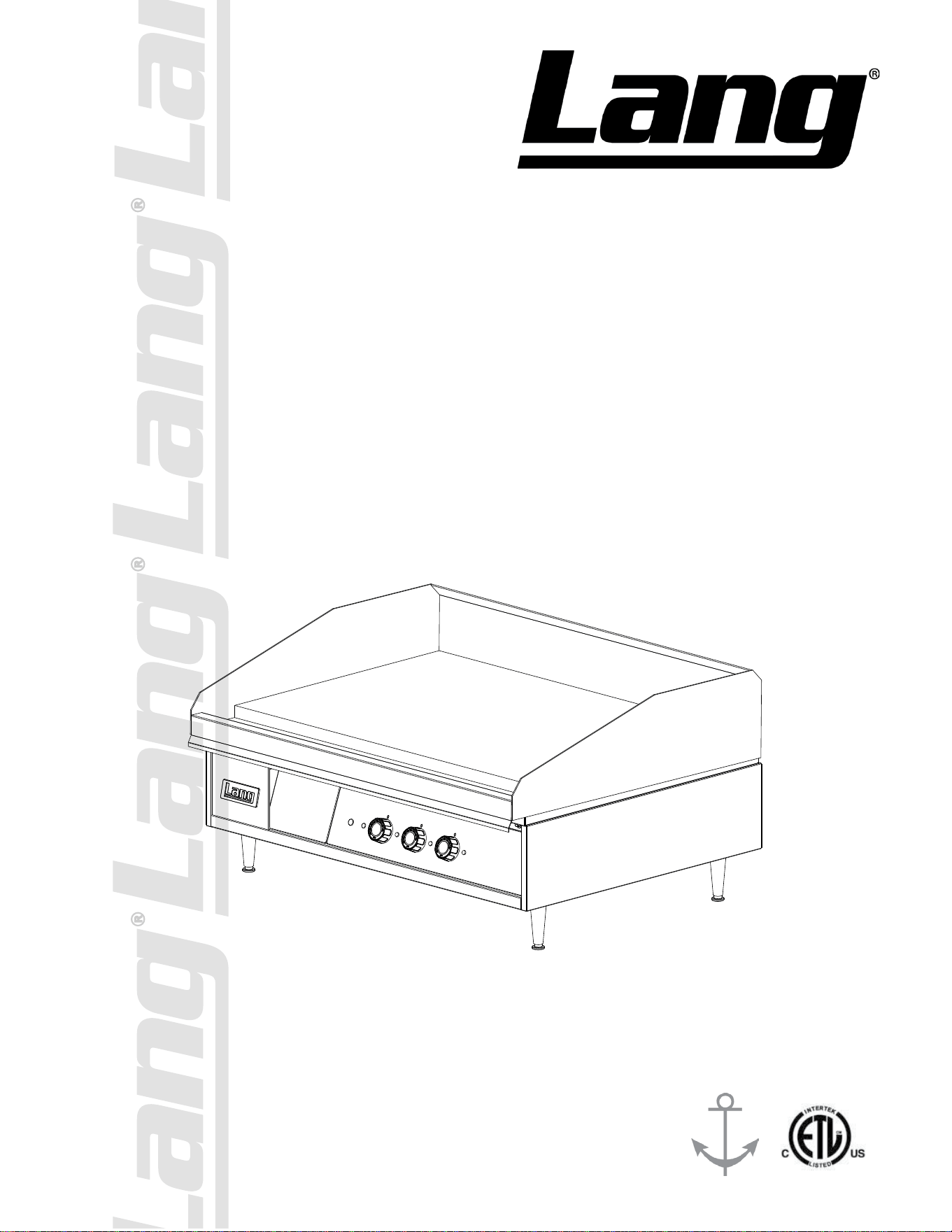
ELECTRIC GRIDDLE
Commercial & Marine
124T, 124TR, 124TC, 124THE, 124TSS
136T, 136TC, 136TNTS, 136THE
148T, 148THE, 148TC, 148TSS
160T, 160TC, 160THE, 160TSS
172T, 172TC, 172TSS, 172TBC
Installation and
Operation
Instructions
2M-W352 Rev. H 4/15/16
136T
2
2M-W352: Thermostatic Electric Griddle, 124T - 172T
These symbols are intended to alert the user to the presence of
important operating and maintenance instructions in the manual
accompanyingtheappliance.
FOR YOUR SAFTEY
DO NOT STORE OR USE GASOLINE OR OTHER FLAMMABLE VAPORS AND LIQUIDS IN
THE VICINTIY OF THIS OR ANY OTHER APPLIANCE.
POST IN PROMINENT LOCATION
INSTRUCTIONS TO BE FOLLOWED IN THE EVENT USER SMELLS GAS. THIS
INFORMATION SHALL BE OBTAINED BY CONSULTING YOUR LOCAL GAS SUPPLIER.
AS A MINIMUM, TURN OFF THE GAS AND CALL YOUR GAS COMPANY AND YOUR
AUTHORIZED SERVICE AGENT. EVACUATE ALL PERSONNEL FROM THE AREA.
WARNING
IMPROPER INSTALLATION, ADJUSTMENT, ALTERATION, SERVICE OR MAINTENANCE
CAN CAUSE PROPERTY DAMAGE, INJURY OR DEATH. READ THE INSTALLATION,
OPERATION & MAINTENANCE INSTRUCTIONS THOROUGHLY BEFORE INSTALLING OR
SERVICING THIS EQUIPMENT.
WARNING
RISK OF FIRE OR ELECTRIC SHOCK
DO NOT OPEN
WARNING, TO REDUCE THE RISK OF ELECTRICAL SHOCK, DO NOT REMOVE
CONTROL PANEL. NO USER-SERVICABLE PARTS INSIDE.
REPAIRS SHOULD BE DONE BY AUTHORIZED SERVICE PERSONNEL ONLY.
NOTICE
Usinganypart otherthangenuine Langfactorysupplied partsrelievesthe manufacturerofall
liability.
Lang reserves the right to change specications and product design without notice. Such
revisions do not entitle the buyer to corresponding changes, improvements, additions or
replacementsforpreviouslypurchasedequipment.
Due to periodic changes in designs, methods, procedures, policies and regulations,
the specications contained in this sheet are subject to change without notice. While
Lang exercises good faith efforts to provide information that is accurate, we are not
responsible for errors or omissions in information provided or conclusions reached as a
result of using the specications. By using the information provided, the user assumes all risks
in connection with such use.
MAINTENANCE AND REPAIRS
Contactyourlocaldealerforserviceorrequiredmaintenance. Pleaserecordthemodelnumber,serial
number, voltage and purchase & Installation Information in the area below and have it ready when you
calltoensureafasterservice.
SAFETY SYMBOL
ModelNo.:
Serial No.:
Voltage:
1-Phase
or3Phase:
PurchasedFrom:
Location:
Purchase
Date:
InstalledDate:

3
2M-W352: Thermostatic Electric Griddle, 124T - 172T
TABLE OF CONTENTS
Specications . . . . . . . . . . . . . . . . . . . . . . . . . . . . 4 - 5
Equipment Description . . . . . . . . . . . . . . . . . . . . . . . . 6
Unpacking . . . . . . . . . . . . . . . . . . . . . . . . . . . . . . . 7
Installation
Leg Installation . . . . . . . . . . . . . . . . . . . . . . . . . . 8
Ventilation & Clearence . . . . . . . . . . . . . . . . . . . . . . 9
Electrical Connection . . . . . . . . . . . . . . . . . . . . . . . 9
Technical Data . . . . . . . . . . . . . . . . . . . . . . . . . . . 9
Phasing . . . . . . . . . . . . . . . . . . . . . . . . . . . . . . 9
Initial Start-Up
Pre-Power On . . . . . . . . . . . . . . . . . . . . . . . . . . . 10
Power On . . . . . . . . . . . . . . . . . . . . . . . . . . . . . 10
Seasoning Cooking Surface . . . . . . . . . . . . . . . . . . . . 10
Operation
General . . . . . . . . . . . . . . . . . . . . . . . . . . . . . .11
Loading the Griddle . . . . . . . . . . . . . . . . . . . . . . . . 11
Suggested Times and Temperatures . . . . . . . . . . . . . . .11
Maintenance
Cleaning . . . . . . . . . . . . . . . . . . . . . . . . . . . . . . 12
Crome Surface Griddle Care . . . . . . . . . . . . . . . . . . .13
Troubleshooting
Symptoms / Possible Causes . . . . . . . . . . . . . . . . . . . 14
Possible Causes / Test . . . . . . . . . . . . . . . . . . . . . .14
Wiring Diagram
208/240VAC . . . . . . . . . . . . . . . . . . . . . . . . . . . . 15
480VAC 3 PHASE . . . . . . . . . . . . . . . . . . . . . . . . . 16
2’ Accu-Temp Electric Grid w/CSE12 Hoods . . . . . . . . . . .17
Exploded View & Parts List . . . . . . . . . . . . . . . . . . . . . 18-23
PROBLEMS, QUESTIONS or CONCERNS
Before you proceed consult you authorized Lang service agent directory
or
Call the Lang Technical Service Department at 314-678-6315
NOTICE Service on this or any other Lang appliance must be performed by
qualied personnel only. Consult your Lang Authorized Service Agent
Directory. You can call our service number 314-678-6315 or visit our
website www.langworld.com for the service agent nearest you.
4
2M-W352: Thermostatic Electric Griddle, 124T - 172T
W
D
H
4” (101.6mm)
2.5”
Elec. Connect.
6.8”
Elec. Connect.
36”
Elec. Connect.
(160 & 172 only)
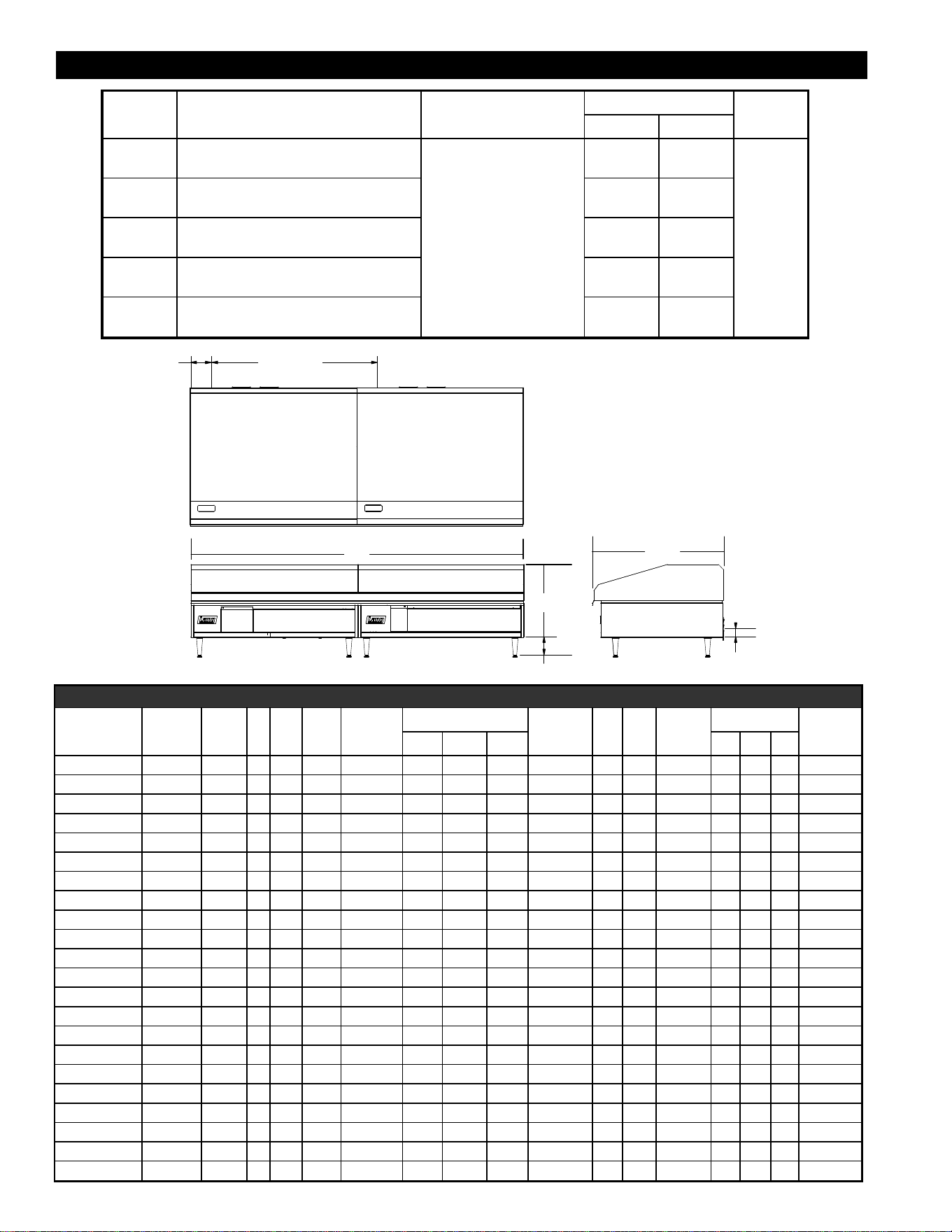
IL1547
Model
Height x Width x Depth Clearance from Weight
Freight
Class(Not including legs) combustible surface Actual Shipping
124
15.0" x 24.0" x 28.2" 243 lbs. 280 lbs.
85
381mm x 610mm x 717mm 110 kg 127 kg
136
15.0" x 36.0" x 28.2" 368 lbs. 410 lbs.
381mm x 914mm x 717mm 167 kg 186 kg
148
15.0" x 48.0" x 28.2"
Sides: 2"
483 lbs. 515 lbs.
381mm x 1219mm x 717mm
Back: 2"
220 kg 234 kg
160
15.0" x 60.0" x 28.2" 621 lbs. 665 lbs.
381mm x 1524mm x 717mm 282 kg 302 kg
172
15.0" x 72.0" x 28.2" 724 lbs. 800 lbs.
381mm x 1830mm x 717mm 329 kg 364 kg
EQUIPMENT SPECIFICATIONS
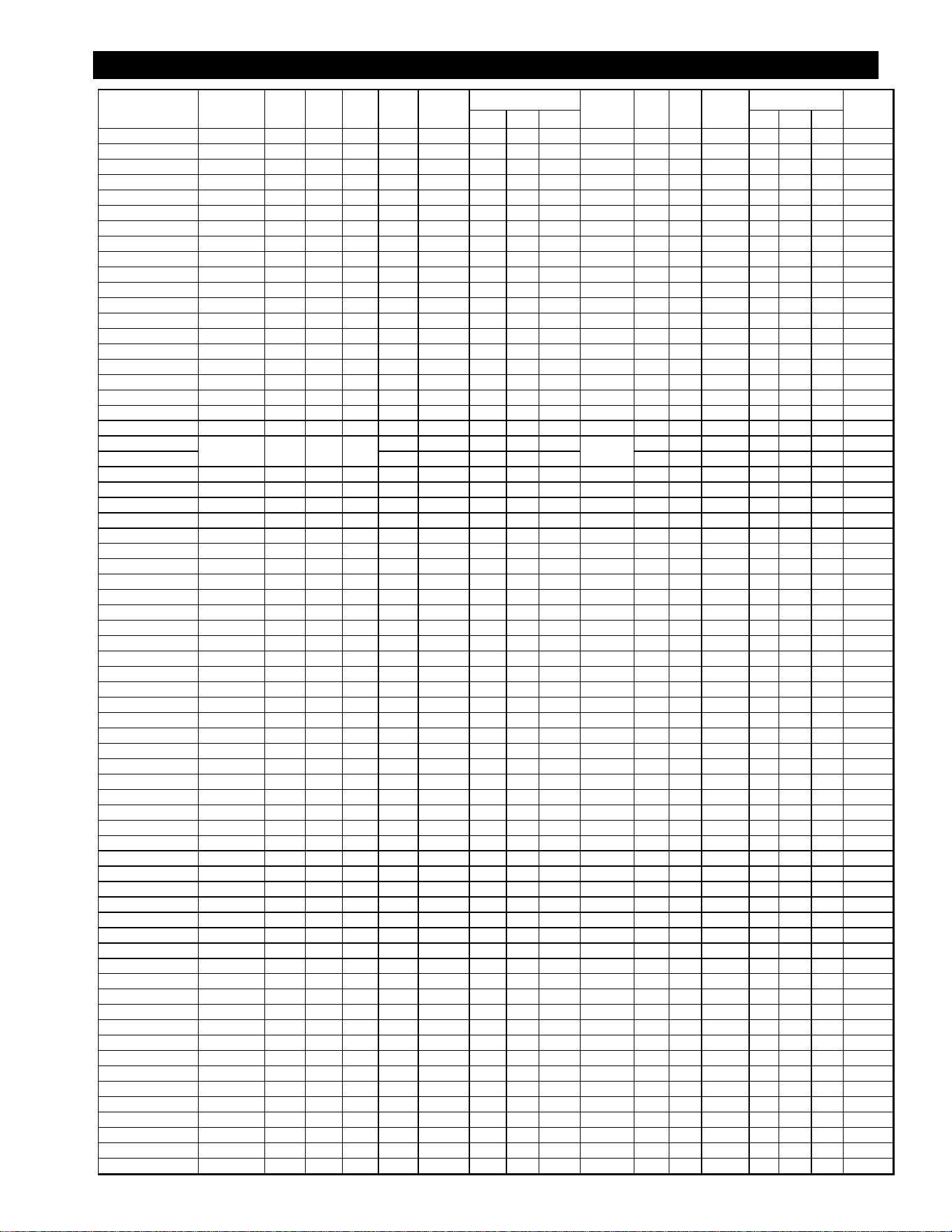
ELECTRICAL SPECIFICATIONS - MARINE
Current Model Volts AC Hz. Ph
Kw
TOT.
Amp
1PH.
Supply Wire
1 PH
Amp 3 Ph
Supply Wire
3 PH
Kw
TOT.
Amp
1PH.
Supply
Wire
1 PH
Amp 3 Ph
Supply Wire
3 PH
L1 L2 L3 L1 L2 L3
124T-380VM 380V 50/60 3 12 27.3 15.7 15.7 10
124T-440VM 440V 50/60 3 12 23.6 13.6 13.6 10
124T-480VM 480V 60 3 12 22 13 13 12
124T-M 208/240V 60 1/3 12 58 4 50 29 29 6
124TC-480VM 480V 60 3 12 22 13 13 12
136T-380VM 380V 60 3 18 27.3 27.3 27.3 10
136T-440VM 440V 60 3 18 23.6 23.6 23.6 12
136T-480VM 480V 60 3 18 22 22 22 12
136TC-440VM 440V 60 1/3 18 87 2 50 50 50 6
136TC-480VM 480V 60 3 18 22 22 22 12
136THE-480VM 480V 50/60 3 18 21.7 21.7 21.7 10
136T-M 208/240V 60 1/3 18 87 2 50 50 50 6
148T-440VM 440V 60 3 24 35.4 35.4 21.7 8
148T-480VM 480V 60 3 24 33 33 22 8
148T-M 208/240V 60 1/3 24 116 1 75 75 50 3
148THE-440VM 440V 60 3 24 35.4 35.4 21.7 8
160T-440VM 440V 60 3 12 23.6 13.6 13.6 10 18 23.6 23.6 23.6 10
160T-480VM 480 60 3 12 22 13 13 12 18 22 22 22 12
160T-M 208/240V 60 1/3 12 58 2 50 29 29 6 18 87 2 50 50 50 6
172T-440VM 440V 60 3 18 23.6 23.6 23.6 12 18 23.6 23.6 23.6 12
172T-480VM 480V 60 3 18 22 22 22 12 18 22 22 22 12
172T-M 208/240V 60 1/3 18 87 2 50 50 50 6 18 87 2 50 50 50 6
5
2M-W352: Thermostatic Electric Griddle, 124T - 172T
EQUIPMENT SPECIFICATIONS
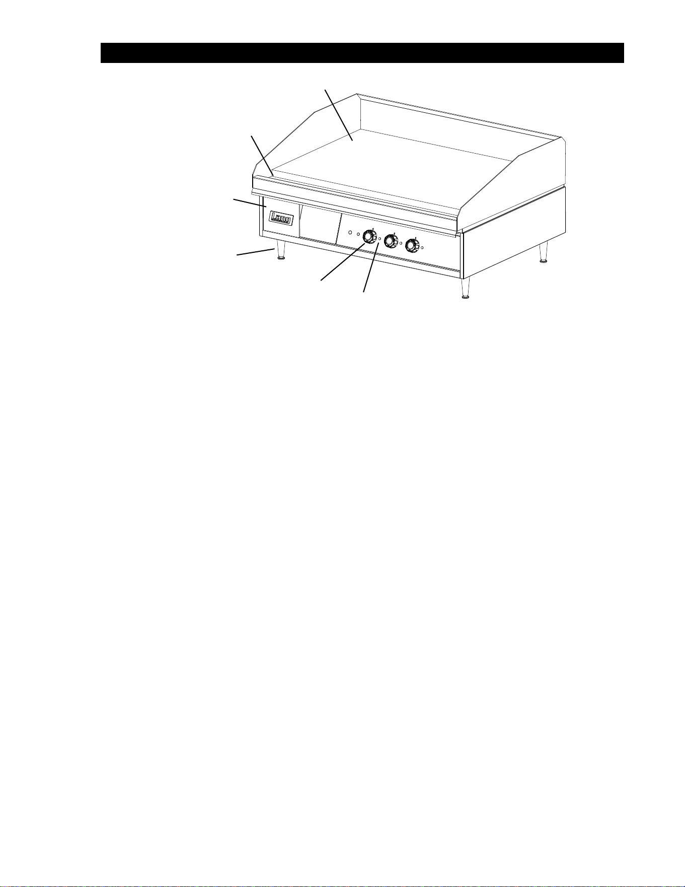
Current Model Volts AC Hz. PH. Kw Tot.
Amp
1PH.
Supply
Wire 1 PH
Amp 3 Ph
Supply
Wire 3 PH
Kw T
ot.
Amp
1PH.
Supply
Wire 1 PH
Amp 3 Ph
Supply
Wire 3 PH
L1 L2 L3 L1 L2 L3
124T 208/240V 60 1/3 12 58 4 50 29 29 6
124T-220V 220V 50/60 1/3 10 45.5 6 39.4 22.7 22.7 8
124T-220VCW 220V 50/60 1/3 10 45.5 6 39.4 22.7 22.7 8
124T-380V 380V 60 3 12 27.3 15.7 15.7 10
124T-480V 480V 60 3 12 22 13 13 12
124T-480VSJ 480V 60 3 12 22 13 13 12
124TB 208/240V 60 1/3 12 58 4 50 29 29 6
124T-BK 208/240V 60 1/3 12 58 4 50 29 29 6
124TC 208/240V 60 1/3 12 58 4 50 29 29 6
124TCHE 208/240V 60 1/3 12 58 4 50 29 29 6
124TC-TE 208/240V 60 1/3 12 58 4 50 29 29 6
124THE 208/240V 60 1/3 12 58 4 50 29 29 6
124THE2L 208/240V 60 1/3 12 58 4 50 29 29 6
124T-PE 208/240V 60 1/3 12 58 4 50 29 29 6
124T-PE-480V 480V 60 3 12 22 13 13 12
124TR 208/240V 60 1/3 12 58 4 50 29 29 6
124TSS 208/240V 60 1/3 12 58 4 50 29 29 6
124TSS-480V 480V 60 3 12 22 13 13 12
136T 208/240V 60 1/3 18 87 2 50 50 50 6
136T-380V 380V 60 3 18 27.3 27.3 27.3 10
136T-480V
480V 60 3 18
22 22 22
12
136T-480VCP 23.6 23.6 23.6
136TC 208/240V 60 3 18 87 2 50 50 50 6
136TC-TE 208/240V 60 1/3 18 87 2 50 50 50 6
136TC-TE-380 380V 50 3 18 27 27 27 10
136THE-240V 208/240V 60 1/3 18 87/75 2 50/43 50/43 50/43 6
136TNTS 208/240V 60 1/3 18 87 2 50 50 50 6
136T-PE 208/240V 60 1/3 18 87 2 50 50 50 6
148T 208/240V 60 1/3 24 116 1 75 75 50 3
148T-480V 480V 60 3 24 33 33 22 8
148TC 208/240V 60 1/3 24 116 1 75 75 50 3
148TC-380V 380 50 3 24 41 41 27 6
148TC-TE 208/240V 60 1/3 24 116 1 75 75 50 3
148TC-TE-380 380V 50 3 24 41 41 27 6
148TC-TE-480 480V 60 3 24 31 33 22 8
148TCHE 208/240 60 1/3 24 116 1 75 75 50 3
148THE 208/240V 60 1/3 24 116 1 75
75 50 3
148T
-PE 208/240V 60 1/3 24 116 1 75 75 50 3
148T-PE-480V 480V 60 3 24 33 33 22 8
148T-SJ 208/240V 60 1/3 24 116 1 75 75 50 3
148TSS 208/240V 60 1/3 24 116 1 75 75 50 3
148TSS-480V 480V 60 3 24 33 33 22 8
160T 208/240V 60 1/3 12 58 2 50 29 29 6 18 87 2 50 50 50 6
160T-PE 208/240V 60 1/3 12 58 4 50 29 29 6 18 87 2 50 50 50 6
160T-440V 440 60 3 12 23.6 13.6 13.6 10 18 23.6 23.6 23.6 10
160T-P-480V 480V 60 3 12 22 13 13 12 18 22 22 22 12
160T-480V 480V 60 3 12 22 13 13 12 18 22 22 22 12
160T-480VCP 480V 60 3 12 22 13 13 12 18 22 22 22 12
160TC-TE 208/240V 60 1/3 12 58 4 50 29 29 6 18 87 2 50 50 50 6
160TC-TE-480 480V 60 3 24 33 33 22 8
160THE 208/240V 60 1/3 12 58 4 50 29 29 6 18 87 2 50 50 50 6
160TSS 208/240V 60 1/3 12 58 2 50 29 29 6 18 87 6 50 50 50 6
160TSS-480V 480V 60 3 12 22 13 13 12 22 22 22 12
172T 208/240V 60 1/3 18 87 2 50 50 50 6 18 87 2 50 50 50 6
172T-380V 380V 50 3 18 27 27 27 10 18 27 27 27 10
172T-480V 480V 60 3 18 22 22 22 12 18 22 22 22 12
172T-480V-CP 480V 60 3 18 22 22 22 12 18 22 22 22 12
172T-480VSJ 480V 60 3 18 22 22 22 12 18 22 22 22 12
172TBC 208/240V 60 1/3 18 87 2 50 50 50 6 18 87 2 50 50 50 6
172TC 208/240V 60 1/3 18 87 2 50 50 50 6 18 87 2 50 50 50 6
172TC-480V 480V 60 3 18 22 22 22 12 18 22 22 22 12
172TC-TE 208/240V 60 1/3 18 87 2 50 50 50 6 18 87 2 50 50 50 6
172TC-TE-380 380V 50 3 18 27 27 27 10 18 27 27 27 10
172T-PE 208/240V 60 1/3 18 87 2 50 50 50 6 18 87 2 50 50 50 6
172T-PE-480V 480V 60 3
18 22 22 22 12 18 22 22 22 12
172T
-SJ 208/240V 60 1/3 18 87 2 50 50 50 6 18 87 2 50 50 50 6
172TSS 208/240V 60 1/3 18 87 2 50 50 50 6 18 87 2 50 50 50 6
172TSS-480V 480V 60 3 18 22 22 22 12 18 22 22 22 12
6
2M-W352: Thermostatic Electric Griddle, 124T - 172T
EQUIPMENT DESCRIPTION
Exterior Construction
The griddle dimensions are 17” (43.18cm) High, 30” (76.20cm) Deep, and width is dependent on the
actual model number.
The Sides, Bottom, and Rear wall are constructed of double wall stainless steel, which allows closer
installation to combustible surfaces.
The griddle surface is made of 1” thick, highly polished steel to reduce hot and cold spots, recovery
problems, warping, and ensure even heat to the edges of the griddle.
Controls
Each twelve-inch section has its own temperature dial that snaps into place to lock in any temperature
from 175°F to 450°F (79°C to 232°C) in 25° increments.
Each twelve-inch section of the griddle is controlled by an area sensitive RTD probe, which can sense
and react to a temperature change of +/- 4°F.
Each twelve-inch section has a set of 6 K.W. elements for high efciency, quick recovery and outstanding
performance
Technical
The 100 series thermostat griddle operates on either 208, 220, 240, 380, 440 or 480V, are shipped three
phase, (unless in specic specications). 208, 220, 240V can be eld converted to single phase.
Minimum clearances: 2” from side and back
NOTICE The data plate is on the right side of the griddle. The griddle voltage,
wattage, serial number, wire size, and clearance specications are on
the data plate. This information should be carefully read and understood
before proceeding with the installation.
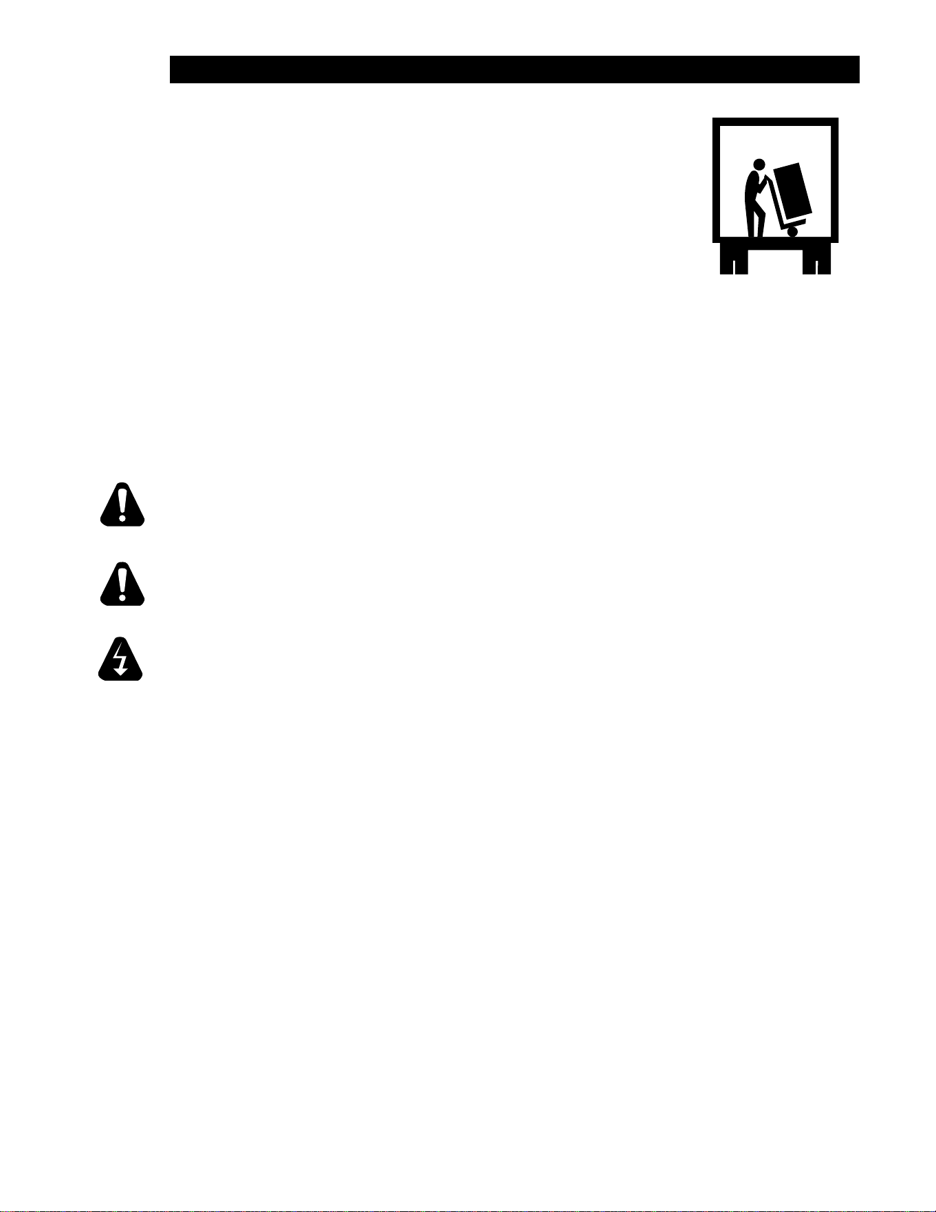
Griddle Surface
Gutter
Grease Pan
Feet
Section
Temp. Dial
Section
Pilot Light
IL1553
7
2M-W352: Thermostatic Electric Griddle, 124T - 172T
UNPACKING
Receiving the Griddle
Upon receipt, check for freight damage, both visible and concealed.
Visible damage should be noted on the freight bill at the time of delivery
and signed by the carrier’s agent. Concealed loss or damage means it
does not become apparent until the merchandise has been unpacked. If
concealed loss or damage is discovered upon unpacking, make a written
request for inspection by the carrier’s agent within 15 days of delivery. All
packing
material should be kept for inspection. Do not return damaged merchan-
dise to Star Manufacturing Company. File your claim with the carrier.
Location
Prior to un-crating, move the griddle as near to its intended location as practical. The crating will help
protect the unit from the physical damage normally associated with moving it through hallways and
doorways.
Un-crating
The griddle will arrive completely assembled inside a wood frame and strapped to a skid. Cut the
straps and remove the wood frame.
The griddle can now be removed from the skid.
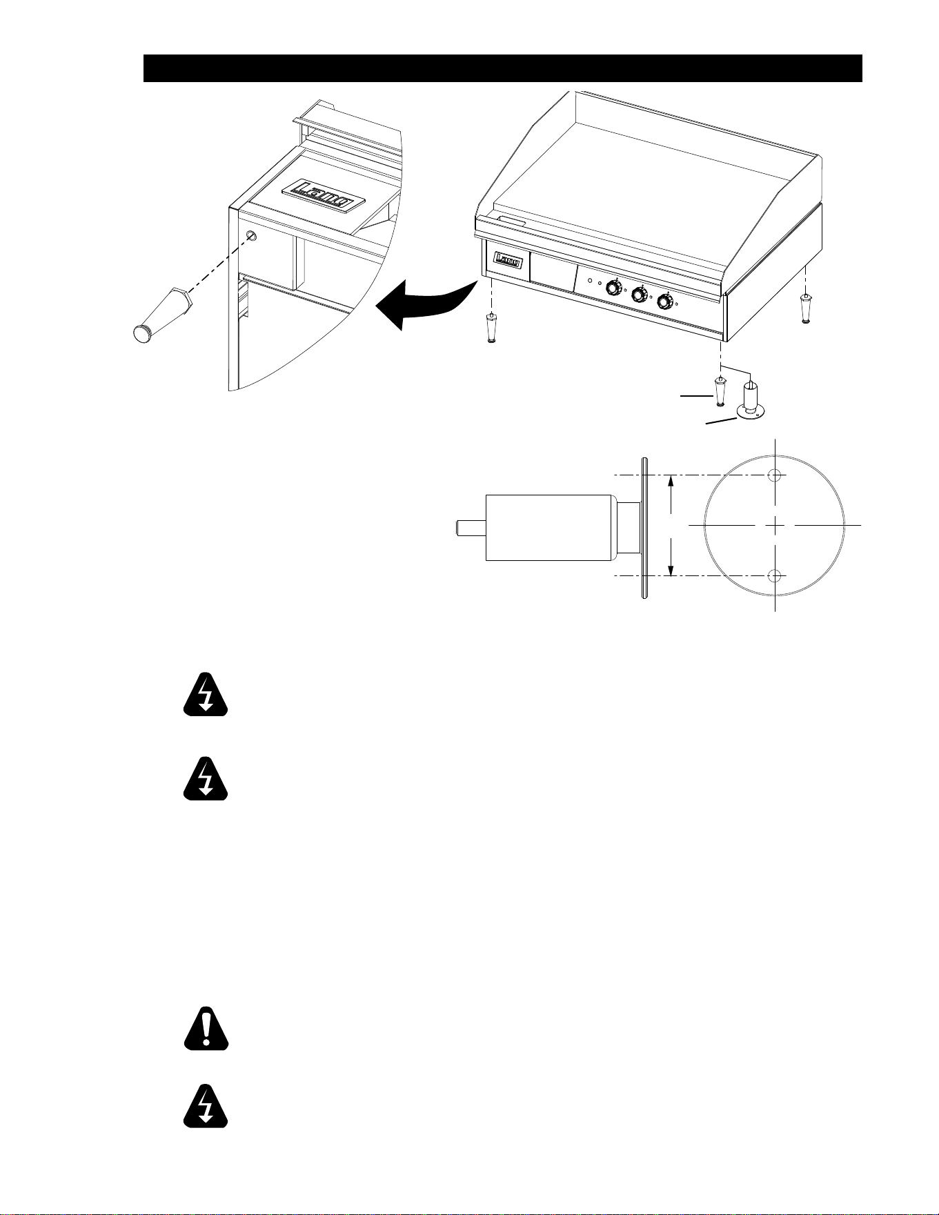
THE UNIT IS EXTREMELY HEAVY. FOR SAFE HANDLING, INSTALLER SHOULD OBTAIN
HELP AS NEEDED, OR EMPLOY APPROPRIATE MATERIALS HANDLING EQUIPMENT
(SUCH AS A FORKLIFT, DOLLY, OR PALLET JACK) TO REMOVE THE UNIT FROM THE
SKID AND MOVE IT TO THE PLACE OF
INSTALLATION.
ANY STAND, COUNTER OR OTHER DEVICE ON WHICH GRIDDLE WILL BE
LOCATED MUST BE DESIGNED TO SUPPORT THE WEIGHT OF THE GRIDDLE.
SHIPPING STRAPS ARE UNDER TENSION AND CAN SNAP BACK WHEN CUT.
CAUTION
CAUTION
WARNING
8
2M-W352: Thermostatic Electric Griddle, 124T - 172T
INSTALLATION
Leg Installation
There are four, 4” legs provided for 2, 3 and
4 foot griddles.
There are eight 4” legs provided for 5 and 6
foot griddles.
The legs are shipped in the grease drawers
of the griddle. Install them into the threaded
holes on the underside of the griddle body.
Leveling adjustment may be done by
screwing the bottom portion of the leg in and out.
IL1554
Std Leg
Marine Bolt Down Leg
: THIS APPLIANCE MUST BE GROUNDED AT THE TERMINAL
PROVIDED. FAILURE TO GROUND THE APPLIANCE COULD RESULT IN
ELECTROCUTION AND DEATH.
INSTALLATION OF THE UNIT MUST BE DONE BY PERSONNEL
QUALIFIED TO WORK WITH ELECTRICITY AND PLUMBING. IMPROPER
INSTALLATION CAN CAUSE INJURY TO PERSONNEL AND/OR DAMAGE
TO EQUIPMENT. UNIT MUST BE INSTALLED IN ACCORDANCE WITH ALL
APPLICABLE CODES.
NOTICE: The data plate is located on the right side of the griddle. The grill voltage,
wattage, serial number, wire size, and clearance specications are on
the data plate. This information should be carefully read and understood
before proceeding with the installation.
NOTICE: The installation of any components such as a vent hood, grease extractors,
re extinguisher systems, must conform to their applicable National, State
and locally recognized installation standards.
ALWAYS KEEP THE AREA NEAR THE APPLIANCE FREE FROM
COMBUSTIBLE MATERIALS.
KEEP FLOOR IN FRONT OF EQUIPMENT CLEAN AND DRY. IF SPILLS
OCCUR, CLEAN IMMEDIATELY, TO AVOID THE DANGER OF SLIPS OR
FALLS.
CAUTION
WARNING
WARNING
WARNING
Above: typical leg installation.
2.5”
IL1550
For bolt down legs see above illustration for dimensions.
9
2M-W352: Thermostatic Electric Griddle, 124T - 172T
INSTALLATION cont.
Ventilation and Clearances
Standard minimum clearance from combustible construction is as follows.
2” from side
2” from back
These griddles may be set directly, without legs, on a curbed base or non-combustible surface.
If the griddle is set without legs on a non-combustible oor or a curbed base, maintain a 4-inch back
clearance.
Do not install the griddle directly against a non-combustible back wall or surface.
Do not install the griddle closer than 12 inches from an uncontrolled heat source (char broiler etc.).
Keep the appliance area free and clear of combustible material and do not obstruct the ow of
combustion or ventilation air.
Electrical Connection
Detach cover on junction box at rear of unit. There is one power supply connection on the 2, 3,
and 4-foot griddles. There are two power supply connections on 5 and 6-foot griddles. Refer to the
power supply chart in the Technical Specication Data portion of this manual (pg 4 & 5), for proper
power supply size.
There is (1) one 1 1/4-inch conduit knockout on 2, 3 and 4-foot griddles located at the rear of the
griddle, through the back and the bottom of the griddle body. There are (2) two 1 1/4-inch conduit
knockouts provided on the 5 and 6-foot griddles. Use a supply wire suitable for at least 90°C/194°F.
This griddle is shipped from the factory set up for a three phase service. On 208V, 220V & 240V the
wiring can be changed in the supply terminal junction box to convert the griddle to single phase.
Technical Data
Re-Phasing
All griddles are shipped from the
factory set up for a three-phase
service. Rearrange the wires in
the power supply terminal block
to convert the griddle to single
phase. Re-phasing the griddle is not
chargeable to Lang Manufacturing
Company as warranty. To convert
to single-phase have a Lang
Authorized Service Agent, follow
this chart.
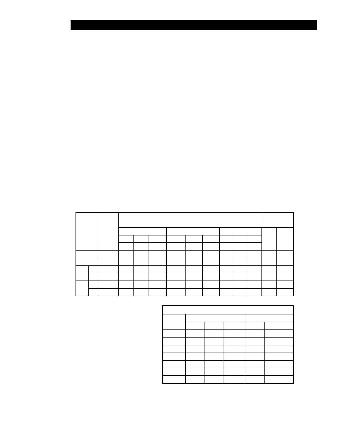
MODEL
NUMBER
TOTAL
K.W.
NOMINAL AMPS PER LINE
SINGLE PHASETHREE PHASE
208 Volt 240 Volt 480 Volt
208V 240VL1 L2 L3 L1 L2 L3 L1 L2 L3
24” 12 50 28.8 28.8 43.3 25 25 21.7 12.5 12.5 57.7 50
36” 18 50 50 50 43.3 43.3 43.3 21.7 21.7 21.7 86.5 75
48” 24 75 75 50 65 65 43.3 32.5 32.5 21.7 115.5 100
60”
#1 18 50 50 50 43.3 43.3 43.3 21.7 21.7 21.7 86.5 75
#2 12 50 28.8 28.8 43.3 25 25 21.7 12.5 12.5 57.7 50
72”
#1 18 50 50 50 43.3 43.3 43.3 21.7 21.7 21.7 86.5 75
#2 18 50 50 50 43.3 43.3 43.3 21.7 21.7 21.7 86.5 75
PHASING BY WIRE NUMBER
MODEL
NUMBER
THREE PHASE SINGLE PHASE
LINE 1 LINE 2 LINE 3 LINE 1 LINE 2
124T 1,4 2 3 1,3 2,4
136T 1,4 2,5 3,6 1,3,5 2,4,6
148T 1,4,7 2,5,8 3,6 1,3,5,7 2,4,6,8
160T #1 1,4 2,5 3,6 1,3,5 2,4,6
160T #2 1,4 2 3 1,3 2,4
172T #1 1,4 2,5 3,6 1,3,5 2,4,6
172T #2 1,4 2,5 3,6 1,3,5 2,4,6

10
2M-W352: Thermostatic Electric Griddle, 124T - 172T
INITIAL START UP
Pre-Power On
Before starting the griddle for the rst time, clean the griddle body and cooking surface.
Use a mild soap and water solution, then rinse with clear water and dry.
The griddle is shipped with a protective coating and craft paper covering the cooking surface.
This MUST be removed before heating the cooking surface. After removing the craft paper, the coating
can be scrapped from the cooking surface and then wiped with a dry cloth.
Power On
Set the temperature dials to 200°F (93°C).
Heat the griddle at 200°F (93°C) for 2 hours to evaporate any moisture that may be in the elements.
Wipe surface again with dry cloth to remove any residue that still remains.
After 2 hours at 200°F (93°C), turn the temperature up to 350°F (176°C) for ½ hour.
After the griddle reaches 350°F (176°C) for ½ hour, turn the griddle up another 50°F (10°C) for another
½ hour and repeat this until it is at 450°F (232°C) for ½ hour.
The unit may emit a small amount of smoke as the cooking surface passes the 300°F (148°C) point.
Do not be alarmed as the smoke is caused by oils associated with the manufacturing process and will
stop when the griddle reaches 350°F (176°C).
Seasoning Cooking Surface
The cooking surface must be “seasoned” in order to eliminate product sticking during cooking.
To season, heat the griddle to 250°F (121°C).
Once at 250°F (121°C), coat the cooking surface with non-salted vegetable oil.
Allow the griddle to stand at 250°F (121°C) until the cooking surface looks dry then coat it again.
Heat the griddle to 350°F (176°C) and repeat the procedure.
NOTICE: During the rst few hours of operation you may notice a small amount of
smoke coming off the griddle, and a faint odor from the smoke. This is
normal for a new griddle and will disappear after the rst few hours of use.
11
2M-W352: Thermostatic Electric Griddle, 124T - 172T
OPERATION
General
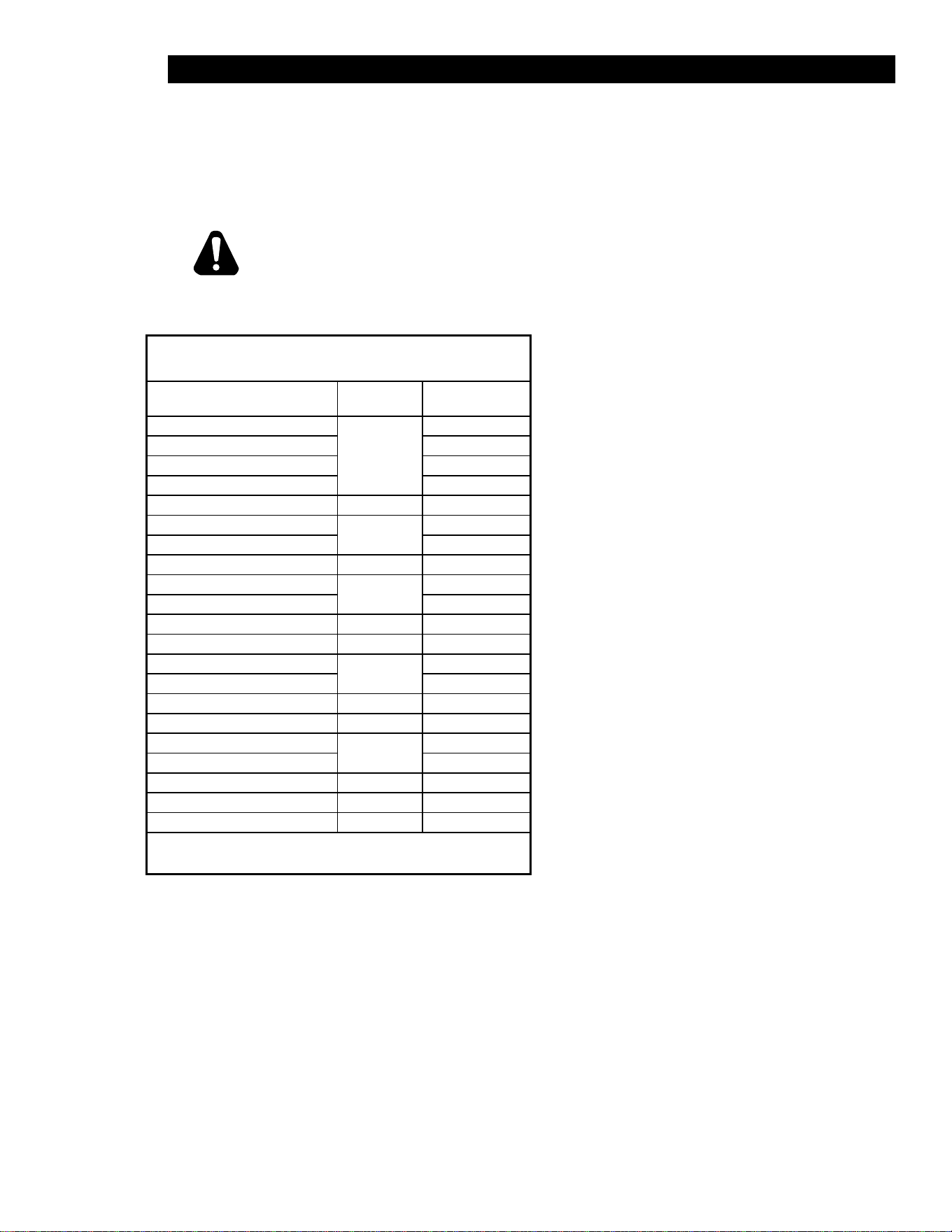
The suggested time and temperature chart (below) is provided as a guide for the products listed only.
If different temperature settings are to be used, select one side of the griddle and operate at the lowest
temperature. Adjoining sections should be set at progressively higher temperatures. Do not try to
operate the end sections hot and the center sections cool.
ALWAYS KEEP THE AREA NEAR THE APPLIANCE FREE FROM COMBUSTIBLE
MATERIALS.
KEEP FLOOR IN FRONT OF EQUIPMENT CLEAN AND DRY. IF SPILLS OCCUR,
CLEAN IMMEDIATELY, TO AVOID THE DANGER OF SLIPS OR FALLS.
Loading the Griddle
An understanding of how the griddle sections
are controlled will be a valuable aid in loading
product on your unit.
Each 12-inch section of your griddle is
independently controlled by a temperature
controller.
The temperature control sensor is mounted in
the center of each cooking section under the
griddle plate.
If the product is loaded directly over the
temperature sensor, that section will turn on and
the burner will heat the entire cooking section.
If the product is loaded to the side, front or back
of the temperature sensor, the thermostat will
react to the temperature change much slower.
During slow periods with minimal loads, do not
load directly over the thermostat sensors as
this will unnecessarily turn the burners on and
overheat the remainder of the section not being
utilized.
Turn the product and continue cooking until it
has reached its desired degree of doneness.
Remove the product from the griddle.
When reloading the griddle, rst use the griddle
surface on which a previous load was not
placed.
This will help insure the proper griddle
temperature.
SUGGESTED TIMES AND TEMPERATURES
PRODUCTS TEMP F / C TIME (MIN)
HAMBURGER
350°F / 176°C
2 patties per LB 6 to 8
4 patties per LB 4 to 6
6 patties per LB 3 to 4
STEAKS
1/2 to 3/4 inch thick, cooked medium
375°F / 190°C
5 to 7
3/4 to 1 inch thick, cooked medium 8 to 10
Lamb Chops
350°F / 176°C
6 to 8
Pork Chops 6 to 8
Salmon 350°F / 176°C 6 to 8
Halibut
325°F / 162°C
6 to 8
Snapper 6 to 8
Hash Brown Potatoes 375°F / 190°C 3 to 4
Bacon
350°F / 176°C
3 to 4
Sausage Links or Patties 3 to 4
Ham (Pre-cooked) 375°F / 190°C 2
Eggs 275°F / 135°C 2 to 4
Note: The times and temperatures in this chart are intended as a general guide and
starting point. Your actual times and temperatures may vary from this chart.
CAUTION
12
2M-W352: Thermostatic Electric Griddle, 124T - 172T
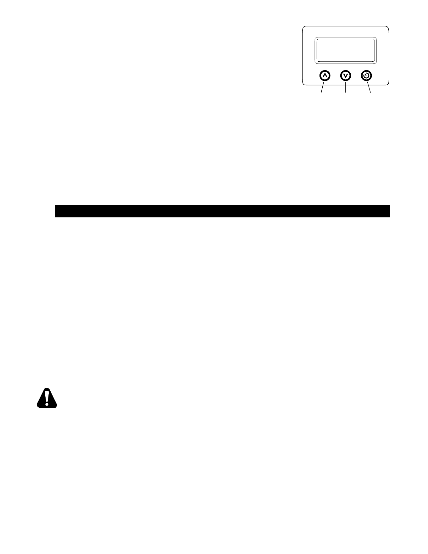
Timer Operation (certain models)
Start Up:
• The current preset time is displayed when the power switch is turned on,
and 3 beeps will sound.
Timer Preset:
• There are 3 programmable timer set points available. Press “+” “-“ button.
• Once a preset time is selected, the “START/STOP” button will start the timer
countdown.
• Press “START/STOP” to stop the buzzer, and reset the timer.
To Change a timer Preset:
• To change a preset time, toggle to that time using the “+” or “-“ buttons.
• Press and hold down the “START/STOP” button for 5 seconds till the shown preset time blinks.
• Keep the “START/STOP” pushed and toggle the time up “+” or down “-“ from the pre-set time.
• The time will now stay at the new pre-set time
Operate Timer:
• Press “START/STOP” to start the time counting down
• When timer reaches “00”, the alarm sounds
• The alarm will not turn off until “START/STOP” is pressed, then the current preset time will be displayed.
• To interrupt while counting down press “START/STOP”.
MAINTENANCE & CLEANING
Cleaning
• Always start with a cold griddle.
• The stainless exterior can easily be cleaned using a good non-abrasive cleaner.
• Always follow the cleaner manufacturer’s instructions when using any cleaner.
• Always apply these cleaners when the griddle is cold and rub in the direction of the metal’s grain.
Griddle Surface Care (non-chromium surfaces)
It takes very little time and effort to keep the griddle attractive and performing at top efciency. If grease
is permitted to accumulate, it will form a gummy cake and then carbonize into a hard substance which is
extremely difcult to remove. To prevent this condition, the following suggestions for cleanliness should be
followed:
• After each use, scrape the griddle with a scraper or exible spatula to remove excess grease and food.
A waste drawer is provided for the scrapings. If there is an accumulation of burned on grease and food,
the griddle should be thoroughly scoured and re-seasoned. Use pumice or griddle stone while the griddle
is warm.
Do not use steel wool because of the danger of steel slivers getting into the food.
Daily Cleaning
Empty the grease drawer or whenever it is 3/4 full. It is easily removed for washing.
USE CAUTION WHEN REMOVING THE RELEASE DRAWER AS IT CONTAINS HOT
GREASE.
Clean the exterior of the appliance with hot water and mild detergent to maintain a gleaming appearance.
Keep the griddle surface clean. After each cooking load scrape the griddle surface to remove any
carbonized grease.
Weekly Cleaning
Once a week or when necessary the griddle surface should be cleaned and seasoned. Use a griddle stone,
griddle pad, or liquid cleaner. Rub with the grain of the metal, being careful not to scrape the splash guard.
A mild detergent with water or one of the many commercial griddle cleaners may be used.
Be sure to rinse thoroughly and coat the cooking surface with a thin lm of oil to prevent rusting.
Season the griddle plate after each cleaning.
WARNING
TIMER
INCREASE+ DECREASE- START/STOP

13
2M-W352: Thermostatic Electric Griddle, 124T - 172T
GRIDDLE CARE (CHROME SURFACES)
(Chrome surface griddles are marked with “CHS” at the end of the model number designation on the nameplate.)
It takes very little time and effort to keep this Industrial Chrome griddle surface sparkling clean and performing at top
efciency. DO NOT allow grease to accumulate as it will carbonize and become difcult to remove.
To prevent this condition, the following cleaning suggestions should be followed:
1. Remove excess oil and food regularly with a 4” (100mm) wide razor sharp type scraper and wipe surface with a
damp cloth if desired.
2. Following the scraping, for end of the day cleaning, a damp cloth and a non-silicated,non-abrasive, non-chlorinated
cleaner such as Bon-Ami may be used to wipe surface clean, followed by wiping with clean wet cloth.
3. Follow daily cleaning steps for Non-Chrome Surfaces.
ON CROME SURFACES:
1. Never use pumice, griddle stones, or abrasives on the surface.
2. Never strike the griddle surface with a sharp instrument or spatula edge.
3. Never use steel wool.
4. Never use commercial liquid grill cleaner on the griddle surface.
5. Abusing the surface voids the warranty.
KEEP WATER AND SOLUTIONS OUT OF CONTROLS. NEVER SPRAY OR HOSE CONTROL CONSOLE.
MOST CLEANERS ARE HARMFUL TO THE SKIN, EYES, MUCOUS MEMBRANES AND CLOTHING.
PRECAUTIONS SHOULD BE TAKEN TO WEAR RUBBER GLOVES, GOGGLES OR FACE SHIELD AND
PROTECTIVE CLOTHING. CAREFULLY READ THE WARNING AND FOLLOW THE DIRECTIONS ON THE
LABEL OF THE CLEANER TO BE USED.
NOTICE: Never leave a chlorine sanitizer in contact with stainless steel surfaces longer than
10 minutes. Longer contact can cause corrosion.
CAUTION
14
2M-W352: Thermostatic Electric Griddle, 124T - 172T
WARNING
CAUTION
TROUBLESHOOTING
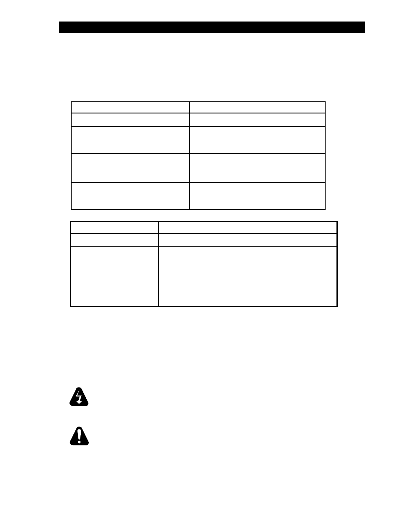
Symptoms
What follows is a chart of Symptoms and Possible Causes to aid in diagnosing faults with the griddle.
Refer to the Symptoms column to locate the type of failure then to the Possible Cause for the items
to be checked.
To test for a possible causes refer to the TEST section and locate the Possible Cause then refer
to test to identify test procedures.
If an item on the list is followed by an asterisk (*), the work should be done by a factory authorized service
representative.
NOTICE: Service on this, or any other, LANG appliance must be performed by qualied
personnel only. Consult your Lang Authorized Service Agent Directory or call
the factory at 314-678-6315, or www.langworld.com For the service agent
nearest you.
BOTH HIGH AND LOW VOLTAGES ARE PRESENT INSIDE THIS APPLIANCE
WHEN THE UNIT IS PLUGGED/WIRED INTO A LIVE RECEPTACLE. BEFORE
REPLACING ANY PARTS, DISCONNECT THE UNIT FROM THE ELECTRIC
POWER SUPPLY.
USE OF ANY REPLACEMENT PARTS OTHER THAN THOSE SUPPLIED
BY LANG OR THEIR AUTHORIZED DISTRIBUTORS CAN CAUSE BODILY
INJURY TO THE OPERATOR AND DAMAGE TO THE EQUIPMENT AND WILL
VOID ALL WARRANTIES.
SYMPTOM POSSIBLE CAUSE
Whole Griddle will not heat • No Power to Griddle
One Section will not heat •
Failed contactor
•
Failed Element.
Product Burning •
Product left on griddle too long
•
Out of Calibration
Product Under cooked •
Product removed too soon
•
Out of Calibration
POSSIBLE CAUSE TEST
Product is cooked too long • No test available, operational condition
Failed Contactor • Remove the wires from the contactor coil and check for
continuity across the contactor coil connection*
•
Ensure the contactor moveable points move freely up
and down*
Failed Element •
Conrm that Elements are getting correct voltage and
have continuity*
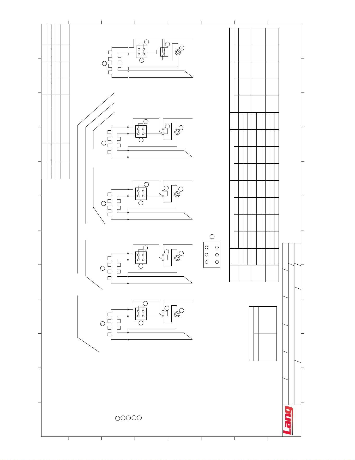
15
2M-W352: Thermostatic Electric Griddle, 124T - 172T
JUMPER
GRIDDLE ELEMENTS1
2
3
4
5
GRIDDLE PILOT LAMP
GRIDDLE THERMOSTAT
TERMINAL BLOCK
L2
5
L3L1
4
*
18
26
25
CONN #2 USE LG36
DLG
2
2
3
4
10
17
2
3
12-13-02
LG72: CONN #1 USE LG36
5
2
3
4
5
2
3
4
5
1
1
1
16
15
23
*
31
LG48
LG36
LG24
22
32
8765
29
30
22
*
14
21
13
43
27
28
20
*
12
19
11
5
1
NOTES:
LG60 & LG72 HAVE TWO POWER SUPPLY CONNECTIONS
LG60: CONN #1 USE LG36
CONN #2 USE LG24
1
9
11
A
B
C
D
DWG. NO:
SHEET OF
DWN. DATE :
DWN. BY :
CHK. BY :
DESCRIPTION:
LANG GRIDDLE 208-240/220VAC
1
Company
Manufacturing
61114-01
REV:
1
G
1
CAD FILE :
FROM ACAD
CHK. DATE :
REV. BY :
REV. DATE :
E
F
G
H
H
G
F
E
D
C
B
A
2
34
5
6
7
8
9
10
11
12
1
2
3
4
5
6
7
8
9
10
12
2 POLE THERMOSTAT.
9
17
10
*
18
26
25
1
2
2
1
5
4
3
NOTE: TYPICAL WIRING FOR EACH
SECTION ON UNITS THAT HAVE A
TYPICAL
208-220 V 240V
INSTALL REMOVE
JUMPER JUMPER
ELEMENT HOOKUP
(ITEM 4) (ITEM 4)
AMPS 1
L1-L2 L2-L3 L1-L3 TOTAL L1 L2 L3 PHASE L1 L2 L3 L1 L2
208 6.0 6.0 12.0 50.0 28.9 28.9 57.7
220 6.7 6.7 13.4 52.9 30.5 30.5 60.9
240 6.0 6.0 12.0 43.3 25.0 25.0 50
208 6.0 6.0 6.0 18.0 50.0 50.0 50.0 86.5
220 6.7 6.7 6.7 20.1 52.9 52.9 52.9 91.4
240 6.0 6.0 6.0 18.0 43.3 43.3 43.3 75
208 12.0 6.0 6.0 24.0 76.0 76.3 50.0 115.4
220 13.4 6.7 6.7 26.8 80.6 80.6 52.9 121.8
240 12.0 6.0 6.0 24.0 66.1 66.1 43.3 100
3,6 1,3,5,7
1,3,5 2,4,6
2,4,6,8
2,4
1,4 2,5 3,6
LG48
LG36
1,4 2
1,4,7 2,5,8
MODEL
LG24
Kw
SERVICE CONNECTIONS
AMP TOTALS
VOLT
THREE PHASE SINGLE PHASE
3 1,3
Revision Block
REV ECN NO. DESCRIPTION DR. MFG. ENG. DATE
E REVISED AND REDRAWN CDS 10/15/2002
F ADDED 220VAC FOR LGCL DLG 12/13/2002
G 6170
ADDED WIRING FOR 2 POLE
TSTAT
DJS 10/1/2007
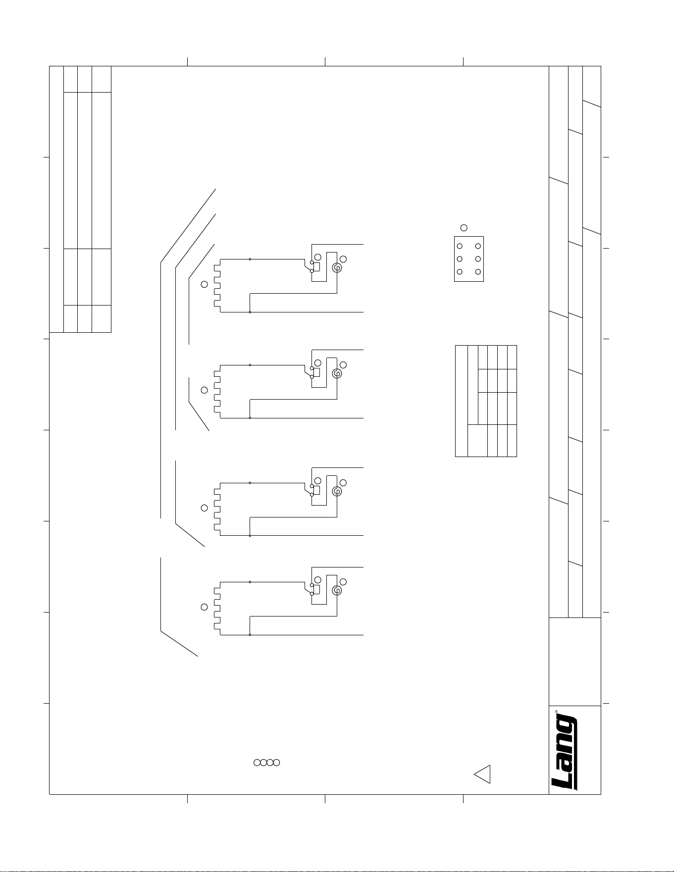
16
2M-W352: Thermostatic Electric Griddle, 124T - 172T
15
31
1
148T
136T
124T
L1 L2 L3
4
NOTES:
160T & 172T HAVE TWO POWER SUPPLY CONNECTIONS.1.
160T: CONN #1 USE 136T; CONN #2 USE 124T
172T: CONN #1 USE 136T; CONN #2 USE 136T
MODELS:2.
380V, 3 PHASE ELECTRIC GRIDDLES
480V, 3 PHASE ELECTRIC GRIDDLES
1 GRIDDLE ELEMENTS
2 GRIDDLE PILOT LAMP
3 GRIDDLE THERMOSTAT
4 TERMINAL BLOCK
3
2
32
8 7
***
* *
6
*
5
*
13
3
29
2
30
* * *
1
4
*
3
*
11
3
27
2
28
* * *
1
2
*
1
*
9
3
25
2
26
* * *
1
WD LANG GRIDDLE 380 & 480 VAC ACCUTEMP
D
61114-02
D
SERVICE CONNECTIONS
MODEL
24
36
48
2,51,4
1,4,7 2,5,8
1,4
L2
2
3,6
3,6
L3
3
L1
THREE PHASE
* NUMBER
CDS
10/15/02
A
B
C
D
DWG. NO:
SHEET
OF
DWN. DATE :
DWN. BY :
CHK. BY :
UNLESS OTHERWISE SPECIFIED
DIMENSIONS ARE IN INCHES.
TOLERANCES ARE:
DECIMALS ANGLES
.X =
±
.05
± .5 °
.XXX =
± .015
BLANK
DIMS. :
DESCRIPTION:
MATERIAL
PART # :
1
2
3
456
7
8
A
B
C
D
1
2
3
4
5
6
7
Company
Manufacturing
8
.XX =
± .03
REV:
1
1
MATERIAL
TYPE :
BLANK
AREA:
X
CAD FILE :
sq
in
CHK. DATE :
REV. BY :
REV. DATE :
REVISIONS
REV. DATE/ECO
DESCRIPTION OF CHANGE
DR
C 10/15/02
REVISED & REDRAWN
CDS
D
2/8/2008
ECO# 6574
ADDED 380V MODEL, REVISED NOTES,
REMOVED AMP TABLE
LRC
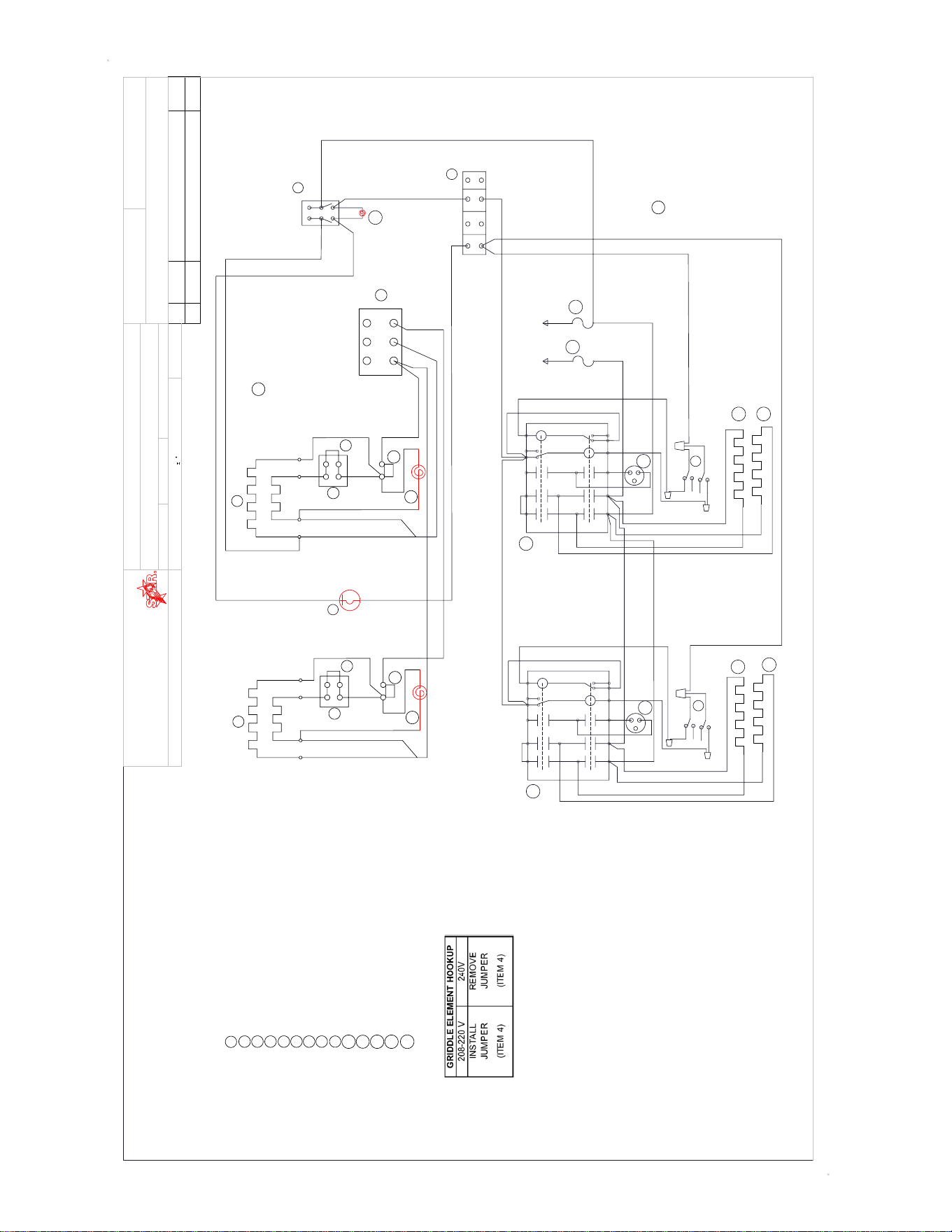
17
2M-W352: Thermostatic Electric Griddle, 124T - 172T
*
1
5
4
2
3
*
1
5
4
2
3
32
1
DOWN
UP
10
10
15
16
4
6
5
3
9
BLU/W
R/W
32
1
DOWN
UP
10
10
15
16
4
6
5
3
9
BLU/W
R/W
5
L3
L2
L1
4
1 2 3
GRIDDLE ELEMENTS
1
2
3
4
5
6
11
10
7
9
8
12
13
GRIDDLE PILOT LAMP
GRIDDLE THERMOSTAT
JUMPER
TERMINAL BLOCK
OVERTEMP STAT #1
HOOD TILT SWITCH
SWITCH
TERMINAL BLOCK - 4 POLE
HOOD ELEMENTS
CONTACTOR
FUSE
TIMER PLUG
14
HOOD PILOT LAMP
R
9
17
10
18
26
2
25
1
CLAMSHELL HOOD #1
CLAMSHELL HOOD #2
3
4
27
20
28
19
11
12
12
12
2
1
10
25
24
21
21
22
22
6
7
14
8
9
9
10
10
10
10
11
11
12
12
13
13
GRIDDLE
CONTACTOR
BOX
CLAMSHELL HOOD
26
CLAMSHELL FIELD
WIRING NOTE:
1 OR 3 PHASE
L1 - 26
L2 - 27
A
GRIDDLE FIELD
WIRING NOTE:
SINGLE PHASE
L1 - 1,3
L2 - 2,4
THREE PHASE
L1 - 1,4
L2 - 2
L3 - 3
A
27
REV.
DATE/ECO
DESCRIPTION OF CHANGE
DR
A
7/23/2008
REVISED GRIDDLE AND CLAMSHELL
WIRING NOTES
JMM
THIS DRAWING CONTAINS INFORMATION CONFIDENTIAL TO STAR MFG. INT'L
INC. NO REPRODUCTION OR DISCLOSURE OF ITS CONTENTS IS PERMITTED
TOLERANCE: UNLESS NOTED: .xxx ± .015
ANGLES 1
REVISIONS
PART NO.
MODEL NO.
TITLE
MATERIAL
FINISH
DR
:
CK.
DATE
:
2M-61114-W51
W/D 2' ACCUTEMP ELECT GRID W/ CSE12 HOODS - 208/240V
7/29/2008
DJS
STAR MANUFACTURING INTERNATIONAL INC.
# 10 SUNNEN DRIVE
ST. LOUIS, MO. 63143, USA
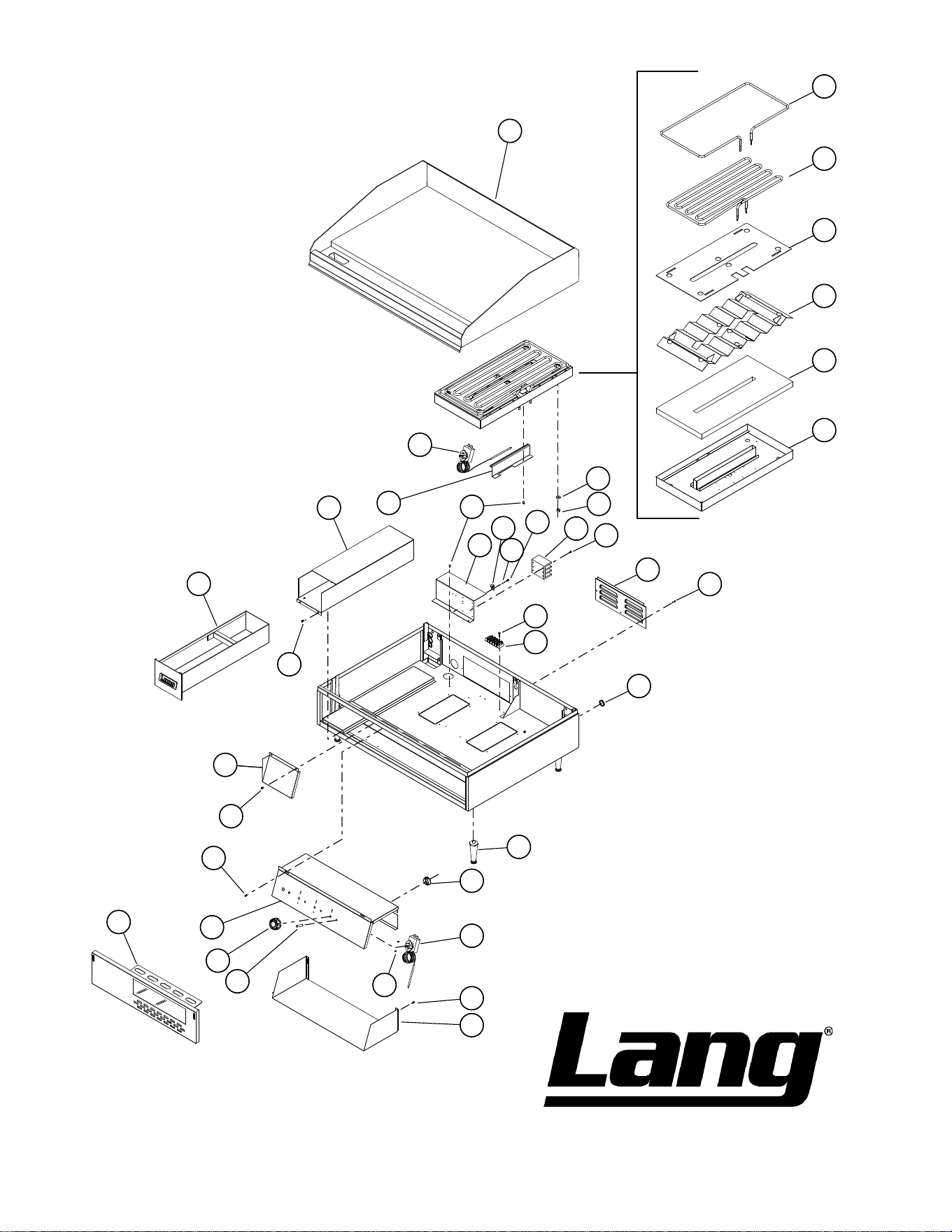
18
2M-W352: Thermostatic Electric Griddle, 124T - 172T
SK2397 Rev. -
8/15/08
1
2
3
4
5
6
7
8
9
14
10
17
15
16
18
19
20
21
10
24
23
25
26
27
10
10
10
29
32
30
22
22
12
13
10
31
10
11
28
Model: Electric Thermostatic Griddle
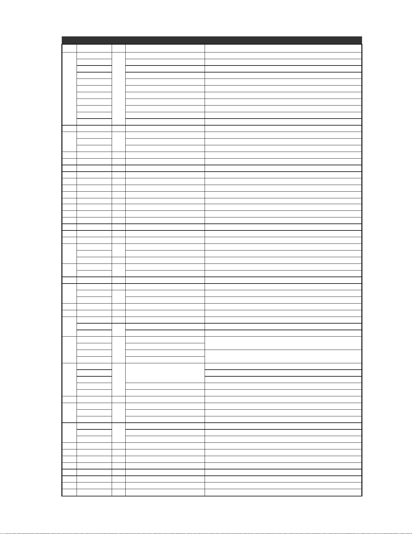
19
2M-W352: Thermostatic Electric Griddle, 124T - 172T
PARTS LIST Rev. H 4/15/2016
Model No: 124T, 124TC, 124THE, 124TSS Accu-Temp Electric Griddle
Fig No Part Number Qty Description Application
1
K9-XL-722-2
1
PLATE ASY 2’ ACU 124T
K9-XL-722-21 PLATE ASY 2’ ACU 4.5 124T-480VSJ, 124TSS, 124TSS-480V
K9-XL-722-211 PLATE ASSY 2’ ACU WITH 4.5 124T-PE, 124T-PE-480V
K9-XL-722-24 PLATE ASY 2’ ACU W/XLH12 124THE, 124THE2L
K9-XL-722-C24 PLATE ASY 2’ ACU W/XLH12 CHRM 124TCHE
K9-XL-722-W21 PLATE ASSY 2’ TALL CROME 124T-V
K9-XL-724-2 PLATE ASY 2’ TALL CHROME 124TC
K9-XL-724-W22 PLATE ASSY 2’ TALL CROME 124TC-VL
K9-XL-724-W24 PLTE ASY 2’ ACU CHRME 3/4H 124TC-TE
K9-XL-718-2 PLATE ASY 2’ ACU REAR GUTR 124TR
K9-XL-718-22 GRIDDLE PLATE ASSY-2’ 124TB
2 2N-11030-30 2 ELMNT GRID 208V 1257W 124T
3
2N-11030-04
2
ELMNT GRID 380V 5991W 124T-380V
2N-11030-29 ELE GRD 208/240V4.5KW/6KW 124T
2N-11030-31 ELMNT GRID 480V 5991W 124T-480V/M, 124T-480VSJ, 124T-PE-480V, 124TSS-480V, 124TC-480VM
4 K9-XL-426 2 ELEMENT PAN PLATE 124T
5 K9-XL-439 2 ELEMENT PAN Z ASSY 124T
6 2H-XL-424 2 ELEMENT PAN INSULATION 124T
7 K9-XL-434 2 ELEMENT PAN ASSEMBLY 124T
8 2C-20201-04 12 WSHR FLT 3/8 USS PLTD 124T
9 2C-20301-06 12 NUT HEX 5/16-18 PLTD 124T
10 2C-20103-02 16 SCRW SM PLT 10 X .5 PHLSL 124T
11 K9-XL-227 1 SUPPLY WIRE BAFFLE 124T
12 Y9-31200-02-1 1 GROUNDING LUG/+LABEL
13 2C-20202-06 1 WSHR LOCK #10 INT STAR
14 2E-30500-07 1 TRM BLOCK 3PLELRGE 125AMP 124T
15 2C-20103-01 4 SCRW SM PLT 10X7/8 PHIL
17 K9-XL-507 1 REAR COVER
18 2C-20104-04 3 SCRW PHD ST 8-32X.5 PLTD PHILP
19
2P-70903-08
1
PLG BTN PLTD MTL 5/16 124T
2P-70903-09 PLG BTN PLTD MTL 7/16 124T
2P-70903-09 4 PLG BTN PLTD MTL 7/16 124T
20
2A-72500-05
4
LEG 4 W/BOLT DOWN ADJ 124T-380VM, 124T-440VM
2A-Z0314 FOOT, 4” DIE CAST 124T
21 2K-70801-02 2 SNAP BUSH 1 3/8 SB1375-16 124T
22
2T-30401-30 1 STAT FXD 550° DEG OPEN 124THE2L
2T-30402-07
2
STAT ADJ 550o 48 C/T (2 Pole) 124T, 124T-220V, 124THE2L
2T-30402-09 STAT ADJ 550° 72 C/T (4 Pole) 124T-220VCW, 124T-480V, 124T-PE, 124T-PE-480V, 124TC-TE, 124TSS, 124TSS-480V
23 2C-20101-77 4 SCRW MS PLT 6-32 X .25 PHD
24 K9-XL-524-1 1 ELECT BOX COVER SPOT 2’ 124T
25
Y9-31601-01-1 2 PILOT LT 250V 6LEAD BLK, w/TIN CLIP 124T, 124T-220V
Y9-31601-01-1
3
PILOT LT 250V 6LEAD BLK, w/TIN CLIP 124THE2L
Y9-31601-02-1 PILOT LT 480V 6LEAD BLK, w/TIN CLIP 124T-380V/M, 124T-480V/M, 124T-480VSJ, 124T-PS-480V, 124TSS-480V
26
Y9-70701-14
2
KNOB ASSY 550°F C, BLACK
124T-220VCW, 124T-480VSJ, 124T-PE, 124T-PE-480V, 124TSS, 124TSS-480V
Y9-70701-14-2 KNOB ASSY 550°F C, RED
Y9-70701-15 KNOB ASSY 550°F D, BLACK
124T, 124T-220V, 124T-480V
Y9-70701-15-2 KNOB ASSY 550°F D, RED
27
K9-XL-725-04
1
ELECT BOX ASY 2’ XL\LG
124T, 124T-220V
K9-XL-725-041 124T-220VCW, 124T-480VSJ, 124T-PE, 124TC-TE, 124TSS
K9-XL-725-04-1 124TCHE-T
K9-XL-725-W13 ELECT BOX ASSY 2’ XL/LG 124THE2L
K9-XL-725-042 ELEC BOX ASSY-2’ ACCU RG 124TR
28 K9-XL-422-1 1 ACCESS PANEL ASSY 2’ 124T
29
K9-50302-07
1
GREASE BUCKET ASSY S/S 124T
K9-XL-235-2 GREASE BUCKET ASSY LGR SS 124TB
K9-XL-235-30 GREASE BUCKET ASY REAR GUTTER 124TR
30
K9-XL-228
1
BUCKET SLIDE ASSY 124T
K9-XL-228-1 BUCKET SLIDE ASSY LGR 124TB
K9-XL-228-30 BKT SLIDE ASSY REAR GUTTER 124TR
31 K9-XL-504 2 STAT HOLDER 124T
NI 2E-30705-01 2 CONTC 2-SPD MTR COIL 240 124THE2L
NI 2E-30900-30 2 FUSE, 60 AMP 124THE2L
NI 2E-30901-14 1 FUSE BLOCK 2 POLE 60AMP 124THE2L
NI 2J-40102-71 1 TIMER 124TCHE-T
NI K9-50302-14 1 2’ GRAB BAR ASSY 124T-MARINE, 124TC-V, 124TC-VL
NI K9-LGCL-234-1 1 DRAWER STOP 124T-MARINE
NI K9-WTGC-24 1 WORK TABLE GRIDDLE COVER 124T-BK
2M-W352: Thermostatic Electric Griddle, 124T - 172T
PARTS LIST Rev. H 4/15/2016
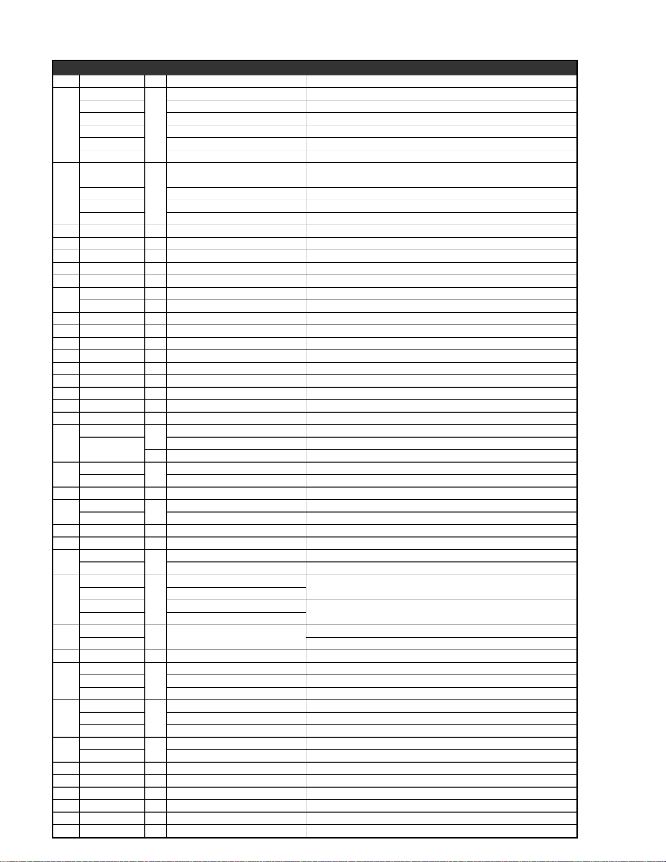
Model No: 136T, 136TC, 136THE Accu-Temp Electric Griddle
Fig No Part Number Qty Description Application
1
K9-XL-0722-3
1
PLATE ASY 3’ ACU 136T, 136T-440VM, 136T-480V, 136TSS
K9-XL-0722-31 PLATE ASSY 3’ ACCU 4.5” 136TSS
K9-XL-0722-311 PLATE ASY 3’ ACT TALL B 136T-PE
K9-XL-0722-W35 PLATE ASY 3’ ACU-NO TAPER 136TNTS
K9-XL-0724-34 PLATE ASSY 3’ ACU W/6.75 136TC-TE, 136THE
K9-XL-0724-W3 PLATE ASSY 3’ ACU CHROME 136TC
2 2N-11030-30 3 ELMNT GRID 208V 1257W 136T
3
2N-11030-04
3
ELMNT GRID 380V 5991W 136TC-TE-380, 136T-380V
2N-11030-29 ELE GRD 208/240V4.5KW/6KW 136T
2N-11030-31 ELMNT GRID 480V 5991W 136T-480V, 136THE-480VM, 136T-PE-480V
2N-11030-48 ELE GRD 440V 5991W 136T-440VM, 136TC-440VM, 136THE-440VM
4 K9-XL-426 3 ELEMENT PAN PLATE 136T
5 K9-XL-439 3 ELEMENT PAN Z ASSY 136T, 136T-440VM, 136T-480V
6 2H-XL-424 3 ELEMENT PAN INSULATION 136T, 136T-440VM, 136T-480V
7 K9-XL-434 3 ELEMENT PAN ASSEMBLY 136T, 136T-440VM, 136T-480V
8 2C-20201-04 18 WSHR FLT 3/8 USS PLTD 136T, 136T-440VM, 136T-480V
9
2C-20103-06 2 SCRW SM PLT 6 X 3/8 PHL 136T, 136T-440VM, 136T-480V
2C-20301-06 18 NUT HEX 5/16-18 PLTD 136T, 136T-440VM, 136T-480V
10 2C-20103-02 18 SCRW SM PLT 10 X .5 PHLSL 136T, 136T-440VM, 136T-480V
11 K9-XL-227 1 SUPPLY WIRE BAFFLE 136T, 136T-440VM, 136T-480V
12 Y9-31200-02-1 1 GROUNDING LUG/+LABEL 136T, 136T-440VM, 136T-480V
13 2C-20202-06 1 WSHR LOCK #10 INT STAR 136T, 136T-440VM, 136T-480V
14 2E-30500-07 1 TRM BLOCK 3PLELRGE 125AMP 136T, 136T-440VM, 136T-480V, 136THE
15 2C-20103-01 4 SCRW SM PLT 10X7/8 PHIL 136T
16 2E-30500-22 1 TRMINL STRP 8POLE 50A250V 136T
17 K9-XL-507 1 REAR COVER 136T
18 2C-20104-04 3 SCRW PHD ST 8-32X.5 PLTD PHILP 136T
19
2P-70903-08
1
PLG BTN PLTD MTL
5/16 136T
2P-70903-09
PLG BTN PLTD MTL 7/16 136T
4 PLG BTN PLTD MTL 7/16 136T
20
2A-72500-05
4
LEG 4 W/BOLT DOWN ADJ 136T-440VM, 136THE-440VM/480VM, 136T-380VM
2A-Z0314 FOOT, 4” DIE CAST 136T
21 2K-70801-02 2 SNAP BUSH 1 3/8 SB1375-16 136T
22
2T-30402-07
3
STAT ADJ 550° 48 C/T 136T (DOOYROWDJHV
2T-30402-09 STAT ADJ 550° 72 C/T 136TC-TE, 136TC-TE-380, 136T-PE, 136TSS
23 2C-20101-77 6 SCRW MS PLT 6-32 X .25 PHD 136T
24 K9-XL-524-2 1 ELECT. BOX COVER 3’ & 4’ 136T
25
Y9-31601-01-1
3
PILOT LT 250V 6LEAD BLK, w/TIN CLIP 136T
Y9-31601-02-1 PILOT LT 480V 6LEAD BLK, w/TIN CLIP 136T-440VM, 136T-480V/M, 136TC-TE-380, 136THE-440/480VM, 136T-PE-480V
26
Y9-70701-14
3
KNOB 550° D, BLACK
136TC-TE, 136TC-TE-380, 136T-PE, 136TSS
Y9-70701-14-2 KNOB 550° D, RED
Y9-70701-15 KNOB 550o D, BLACK
136T
Y9-70701-15-2 KNOB 550o D, RED
27
K9-XL-725-08
1 ELECT BOX ASY 3’ XL\LG
136T
K9-XL-725-081 136TC-TE, 136T-PE, 136TSS
28 K9-XL-422-2 1 ACCESS PANEL ASSY 3’ 136T
29
K9-50302-07
1
GREASE BUCKET ASSY S/S 136T
K9-XL-235-2 GREASE BUCKET ASSY S/S 136SB
K9-XL-235-30 BUCKET SLIDE ASSY REAR 136SR
30
K9-XL-228
1
BUCKET SLIDE ASSY 136T
K9-XL-228-1 BUCKET SLIDE ASSY FNT & REAR
K9-XL-228-30 BUCKET SLIDE ASSY REAR
31
K9-XL-504
3
STAT HOLDER 136T
K9-XL-506 BULB HOLDER ASSY ELECTRIC 136TSS
32 K9-XL-759-3 1 PANEL COVER ASSY 3’ - CP CORRECTIONAL PACKAGE
NI K9-50302-15 1 3’ GRAB BAR ASSY 136T-440VM, 136THE-VM, 136T-380VM
NI K9-LGCL-234-1 1 DRAWER STOP 136T-440VM, 136THE-VM, 136T-380VM
NI 2P-50100-15 1 GRIDDLE SCRAPER 12” CHROME UNITS
NI 2P-50100-16 1 BOM AMI CLEANER CHROME UNITS
NI 2P-50100-17 1 20” PALMYRA BRUSH CHROME UNITS
2M-W352: Thermostatic Electric Griddle, 124T - 172T
PARTS LIST Rev. H 4/15/2016
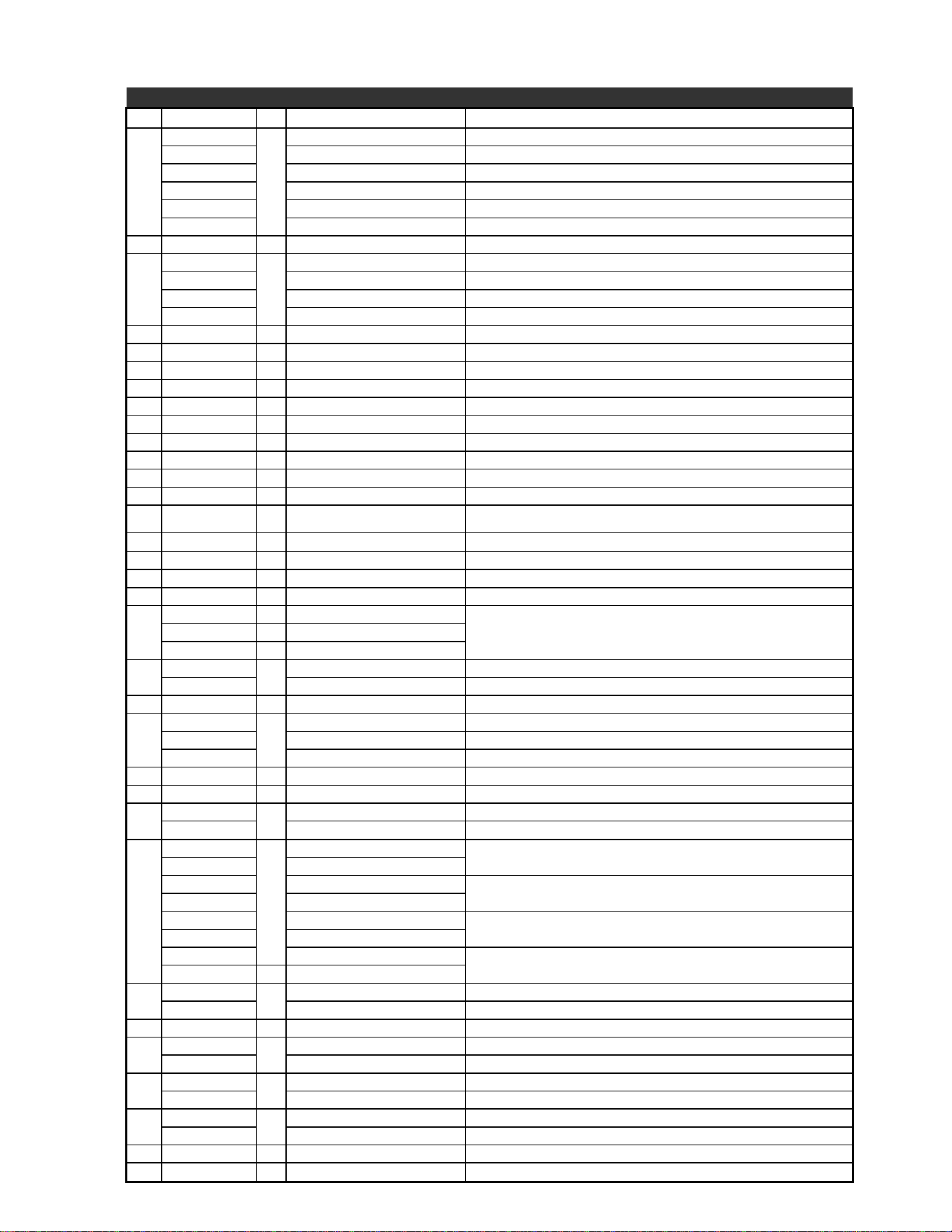
Model No: 148T, 148TC, 148TSS, 148THS Accu-Temp Electric Griddle
Fig No Part Number Qty Description Application
1
K9-XL-722-4
1
PLATE ASY 4’ ACU 148T
K9-XL-722-41 PLATE ASY 4’ ACU 4.5 148T-SJ, 148TSS
K9-XL-722-411 PLATE ASY 4’ ACU TALL B 148T-PE
K9-XL-722-44 PLATE ASY 4’ ACU CHRME 3/4H 148TC-TE, 148THE
K9-XL-0724-41 PLATE ASSY 4’ ACCU 148TCHE
K9-XL-724-4 PLATE ASY 4’ ACU CHROME 148TC, 148TC-TE
2 2N-11030-30 4 ELMNT GRID 208V 1257W ALL
3
2N-11030-04
4
ELMNT GRID 380V 5991W 148TC-TE-380, 148TC-380V
2N-11030-29 ELE GRD 208/240V4.5KW/6KW 148T
2N-11030-31 ELMNT GRID 480V 5991W 148T-480V, 148TSS-480V, 148TC-TE-480
2N-11030-48 ELE GRD 440V 5991W 148T-440VM, 148THE-440VM
4 K9-XL-426 4 ELEMENT PAN PLATE ALL
5 K9-XL-439 4 ELEMENT PAN Z ASSY ALL
6 2H-XL-424 4 ELEMENT PAN INSULATION ALL
7 K9-XL-434 3 ELEMENT PAN ASSEMBLY ALL
8 2C-20201-04 24 WSHR FLT 3/8 USS PLTD ALL
9 2C-20301-06 24 NUT HEX 5/16-18 PLTD ALL
10 2C-20103-02 15 SCRW SM PLT 10 X .5 PHLSL ALL
11 K9-XL-227 1 SUPPLY WIRE BAFFLE ALL
12 Y9-31200-02-1 1 GROUNDING LUG/+LABEL ALL
13 2C-20202-06 1 WSHR LOCK #10 INT STAR ALL
14 2E-30500-07 1 TRM BLOCK 3PLELRGE 125AMP
148T, 148T-M, 148TC,148TH-208/240V, 148T-SJ, 148TC-TE, 148TSS, 148THS-208/240V,
148T-440VM, 148T-480V/M, 148TC-TE-380, 148TSS-480V
15 2C-20103-01 4 SCRW SM PLT 10X7/8 PHIL 148T, 148T-M, 148TC,148TH-208/240V, 148T-SJ, 148TC-TE, 148TSS, 148THS-208/240V
16 2E-30500-22 1 TRMINL STRP 8POLE 50A250V 148T, 148T-M, 148TC,148TH-208/240V, 148T-SJ, 148TC-TE, 148TSS, 148THS-208/240V
17 K9-XL-507 2 REAR COVER ALL
18 2C-20104-04 6 SCRW PHD ST 8-32X.5 PLTD PHILP ALL
19
2P-70903-02 2 PLG BTN PLTD MTL 1/2
ALL2P-70903-08 1 PLG BTN PLTD MTL 5/16
2P-70903-09 3 PLG BTN PLTD MTL 7/16
20
2A-72500-05
4
LEG 4 W/BOLT DOWN ADJ ALL MARINE APPLICATIONS
2A-Z0314 FOOT, 4” DIE CAST 148T
21 2K-70801-02 2 SNAP BUSH 1 3/8 SB1375-16 ALL
22
2T-30402-07
4
STAT ADJ 550o 48 C/T 148T, 148TC
2T-30402-08 STAT ADJ 450° 72 C/T 148T-440VM
2T-30402-09 STAT ADJ 550° 72 C/T 148T-SJ, 148TC-TE, 148TSS, 148T-PE
23 2C-20101-77 8 SCRW MS PLT 6-32 X .25 PHD ALL
24 K9-XL-524-2 1 ELECT. BOX COVER 3’ & 4’ ALL
25
Y9-31601-01-1
4
PILOT LT 250V 6LEAD BLK, w/TIN CLIP 148T
Y9-31601-02-1 PILOT LT 480V 6LEAD BLK, w/TIN CLIP 148T-440VM, 148T-480V, 148TC-TE-380, 148TSS-480V, 148TC-380V, 148THE-440VM
26
Y9-70701-12
4
KNOB ASSY 550° A, BLACK
148T-480V
Y9-70701-12-2 KNOB ASSY 550° A, RED
Y9-70701-14 KNOB 550° D, BLACK
148T-SJ, 148TC-TE, 148TSS, 148T-PE
Y9-70701-14-2 KNOB 550° D, RED
Y9-70701-15 KNOB 550° D, BLACK
148T
Y9-70701-15-2 KNOB 550° D, RED
Y9-70701-19 KNOB 450° D, BLACK
148T-440VM
Y9-70701-19-2 KNOB 450° D, RED
27
K9-XL-725-12
1
ELECT BOX ASY 4’ XL\LG ALL
K9-XL-725-121 ELECT BOX ASY 4’ XL\LG 148T-SJ, 148TC-TE, 148TSS, 148T-PE
28 K9-XL-422-3 1 ACCESS PANEL ASSY 4’ ALL
29
K9-50302-07
1
GREASE BUCKET ASSY S/S ALL
K9-XL-235-2 GREASE BUCKET ASSY S/S 148SB
30
K9-XL-228
1
BUCKET SLIDE ASSY ALL
K9-XL-228-1 BUCKET SLIDE ASSY FNT & REAR 148SB
31
K9-XL-504
4
STAT HOLDER
K9-XL-506 BULB HOLDER ASSY ELECTRIC 148TCHE
NI K9-50302-16 1 4’ GRAB BAR ASSY MARINE APPLICATIONS
NI K9-LGCL-234-1 1 DRAWER STOP MARINE APPLICATIONS
2M-W352: Thermostatic Electric Griddle, 124T - 172T
PARTS LIST Rev. H 4/15/2016
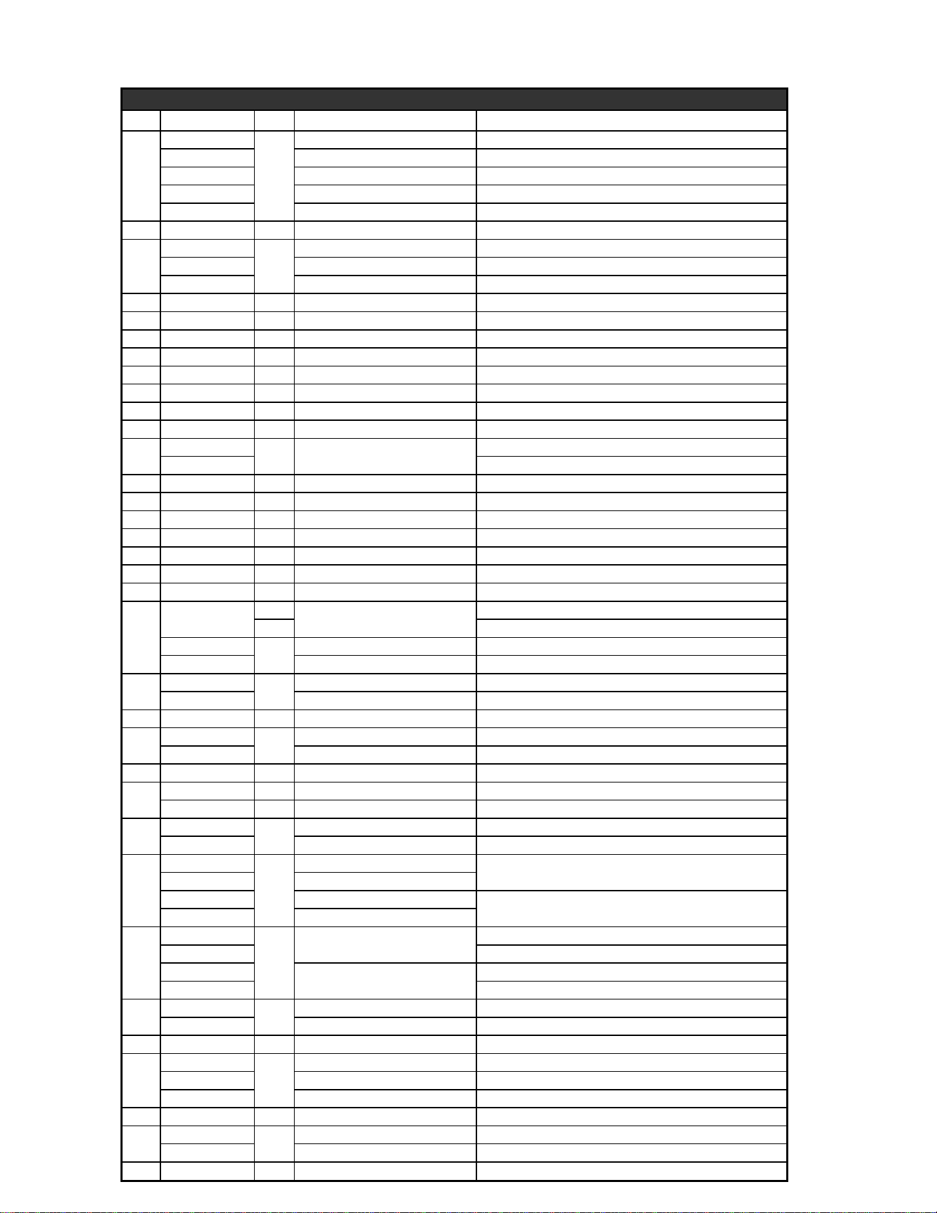
Model No: 160T, 160TC, 160TSS Accu-Temp Electric Griddle
Fig No Part Number Qty Description Application
1
K9-XL-0722-5
1
PLATE ASY 5’ ACU 160T
K9-XL-0722-51 PLATE ASY 5’ ACU 4.5 160TSS
K9-XL-722-511 PLATE ASY 5’ ACU TALL 160T-PE
K9-XL-0724-54 PLATE ASY 5’ ACU CHRME 3/4” 160TC-TE, 160THE
K9-XL-722-P5 PLATE ASSY 5’ W/PARTITION 160T-P-480V
2 2N-11030-30 5 ELMNT GRID 208V 1257W 160T
3
2N-11030-29
5
ELE GRD 208/240V4.5KW/6KW 160T
2N-11030-31 ELMNT GRID 480V 5991W 160T-480V, 160TSS-480V
2N-11030-48 ELE GRD 440V 5991W 160T-440VM
4 K9-XL-426 5 ELEMENT PAN PLATE 160T
5 K9-XL-439 5 ELEMENT PAN Z ASSY 160T
6 2H-XL-424 5 ELEMENT PAN INSULATION 160T
7 K9-XL-434 5 ELEMENT PAN ASSEMBLY 160T
8 2C-20201-04 30 WSHR FLT 3/8 USS PLTD 160T
9 2C-20301-06 30 NUT HEX 5/16-18 PLTD 160T
10 2C-20103-02 34 SCRW SM PLT 10 X .5 PHLSL 160T
11 K9-XL-227 2 SUPPLY WIRE BAFFLE 160T
12
2E-31200-02
2 GROUNDING LUG/+LABEL
208/240V
Y9-31200-02-1 480V
13 2C-20202-06 2 WSHR LOCK #10 INT STAR 160T
14 2E-30500-07 2 TRM BLOCK 3PLELRGE 125AMP 160T
15 2C-20103-01 8 SCRW SM PLT 10X7/8 PHIL 160T
16 2E-30500-20 2 TERMINAL STRIP 4 POLE 50A 250V 160T-208/240V
16 2E-30500-22 2 TRMINL STRP 8POLE 50A250V 160T
17 K9-XL-507 2 REAR COVER 160T
18 2C-20104-04 6 SCRW PHD ST 8-32X.5 PLTD PHILP 160T
19
2P-70803-02
2
PLG BTN PLTD MTL 1/2
160T-208/240V
8 160TSS
2P-70903-08
2
PLG BTN PLTD MTL 5/16 160T
2P-70903-09 PLG BTN PLTD MTL 7/16 160T
20
2A-72500-05
8
LEG 4 W/BOLT DOWN ADJ MARINE APPLICATIONS
2A-Z0314 FOOT, 4” DIE CAST 160T
21 2K-70801-02 4 SNAP BUSH 1 3/8 SB1375-16 160T
22
2T-30402-07
5
STAT ADJ 550o 48 C/T 160T
2T-30402-09 STAT ADJ 550° 72 C/T 160TC-TE, 160TSS, 160T-PE
23 2C-20101-77 10 SCRW MS PLT 6-32 X .25 PHD
24
K9-XL-524-1 1 ELECT BOX COVER SPOT 2’ 160T
K9-XL-524-2 1 ELECT. BOX COVER 3’ & 4’ 160T
25
Y9-31601-01-1
5
PILOT LT 250V 6LEAD BLK, w/TIN CLIP 160T
Y9-31601-02-1 PILOT LT 480V 6LEAD BLK, w/TIN CLIP 160T-480V, 160TSS-480V, 160T-440VM
26
Y9-70701-14
5
KNOB ASSY 550° D, BLACK
160TC-TE, 160TSS, 160T-PE
Y9-70701-14-2 KNOB ASSY 550° D, RED
Y9-70701-15 KNOB ASSY 550° D, BLACK
160T
Y9-70701-15-2 KNOB ASSY 550° D, RED
27
K9-XL-725-04
1
ELECT BOX ASY 2’ XL\LG
160T
K9-XL-725-041 160TC-TE, 160TSS, 160T-PE
K9-XL-725-08
ELECT BOX ASY 3’ XL\LG
160T
K9-XL-725-081 160TC-TE, 160TSS, 160T-PE
28
K9-XL-422-1
1
ACCESS PANEL ASSY 2’ 160T
K9-XL-422-2 ACCESS PANEL ASSY 3’ 160T
29 K9-50302-07 2 GREASE BUCKET ASSY S/S 160T
30
K9-XL-228
2
BUCKET SLIDE ASSY 160T
K9-XL-228-1 BUCKET SLIDE ASSY FNT & REAR
K9-XL-228-30 BUCKET SLIDE ASSY REAR
31 K9-XL-504 5 STAT HOLDER 160T
32
K9-XL-759-2
1
PANEL COVER ASSY 2’ - CP CORRECTIONAL PKG
K9-XL-759-3 PANEL COVER ASSY 3’ - CP CORRECTIONAL PKG
NI K9-50302-21 1 5’ GRAB BAR SUPPORT - XL-LG MARINE APPLICATIONS
2M-W352: Thermostatic Electric Griddle, 124T - 172T
PARTS LIST Rev. H 4/15/2016
Model No: 172T, 172TC, 172TSS Accu-Temp Electric Griddle
Fig No Part Number Qty Description Application
1
K9-XL-719-611
1
PLATE ASSY 6’ ACCU-REAR 172TCR
K9-XL-720-61 TOP PLATE ASSY 6” LGR 172TBC
K9-XL-0722-6 PLATE ASY 5’ ACU 172T
K9-XL-0722-61 PLATE ASY 6’ ACU 4.5 172T-480VSJ, 172T-SJ, 172TSS
K9-XL-0722-611 PLATE ASY 6’ ACU TALL 172T-PE
K9-XL-724-6 PLATE ASY 6’ ACU CHROME 172TC
K9-XL-724-64 PLTE ASY 6’ACU CHRME 3/4H 172TC-TE
2 2N-11030-30 6 ELMNT GRID 208V 1257W 172T
3
2N-11030-29
6
ELE GRD 208/240V4.5KW/6KW 172T
2N-11030-04 ELMNT GRID 380V 5991W 172T-380V
2N-11030-31 ELMNT GRID 480V 5991W 172T-480V, 172TC-480V 172T-480VSJ, 172T-PE-480V
2N-11030-48 ELE GRD 440V 5991W XL/LG 172T-440VM
4 K9-XL-426 6 ELEMENT PAN PLATE 172T
5 K9-XL-439 6 ELEMENT PAN Z ASSY 172T
6 2H-XL-424 6 ELEMENT PAN INSULATION 172T
7 K9-XL-434 6 ELEMENT PAN ASSEMBLY 172T
8 2C-20201-04 36 WSHR FLT 3/8 USS PLTD 172T
9 2C-20301-06 36 NUT HEX 5/16-18 PLTD 172T
10 2C-20103-02 36 SCRW SM PLT 10 X .5 PHLSL 172T
11 K9-XL-227 2 SUPPLY WIRE BAFFLE 172T
12 2E-31200-02 2 GROUNDING LUG/+LABEL 172T, 172T-M
13 2C-20202-06 2 WSHR LOCK #10 INT STAR 172T, 172T-M
14
2E-30500-07 2 TRM BLOCK 3PLELRGE 125AMP
172T, 172T-440VM, 172T-480V, 172TC-480V 172T-480VSJ, 172T-PE-480V,
172TSS-480V
2E-30500-02 2 TRM STRP 4 POLE 30A, 600V 172T-380V
15 2C-20103-01 12 SCRW SM PLT 10X7/8 PHIL 172T
16 2E-30500-22 2 TRMINL STRP 8POLE 50A250V 172T, 172T-PE, 172TSS
17 K9-XL-507 2 REAR COVER 172T
18 2C-20104-04 6 SCRW PHD ST 8-32X.5 PLTD PHILP 172T
19
2P-70903-08 2 PLG BTN PLTD MTL 5/16 172T
2P-70903-09 10 PLG BTN PLTD MTL 7/16 172T
20
2A-72500-05
8
LEG 4 W/BOLT DOWN ADJ 172T-M, 172T-440VM, 172T-480VM
2A-Z0314 FOOT, 4” DIE CAST 172T
21 2K-70801-02 4
SNAP BUSH 1 3/8 SB1375-16 172T
22
2T-30402-07
6
STAT ADJ 550° 48 C/T 172T (all voltages)
2T-30402-09 STAT ADJ 550° 72 C/T 172T-480VSJ, 172T-PE, 172T-SJ, 172TC-TE, 172TSS
23 2C-20101-77 12 SCRW MS PLT 6-32 X .25 PHD 172T
24 K9-XL-524-2 2 ELECT BOX CVER SPT 3’ & 4’ 172T
25
Y9-31601-01-1
6
PILOT LT 250V 6LEAD BLK, w/TIN CLIP 172T
Y9-31601-02-1 PILOT LT 480V 6LEAD BLK, w/TIN CLIP
172T-440VM, 172T-480V, 172TC-480V 172T-480VSJ, 172T-PE-480V, 172TSS-
480V, 172T-380V
26
Y9-70701-14
6
KNOB ASSY 550° D, BLACK
172T-480VSJ, 172T-PE, 172T-SJ, 172TC-TE, 172TSS
Y9-70701-14-2 KNOB ASSY 550° D, RED
Y9-70701-15 KNOB ASSY 550° D, BLACK
172T, 172T-440VM
Y9-70701-15-2 KNOB ASSY 550° D, RED
27
K9-XL-725-08
2
ELECT BOX ASY 3’ XL\LG 172T
K9-XL-725-081 ELECT BOX ASY 3’ XL\LG 172T-480VSJ, 172T-PE, 172T-SJ, 172TC-TE, 172TSS
28 K9-XL-422-2 2 ACCESS PANEL ASSY 3’ 172T
29
K9-50302-07
2
GREASE BUCKET ASSY S/S 172T
K9-XL-235-2 GREASE BUCKET ASSY LGR S/S 172TBC
K9-XL-235-30 GREASE BKT ASY REAR GUTTER 172TCR
30
K9-XL-228
2
BUCKET SLIDE ASSY 172T
K9-XL-228-1 BUCKET SLIDE ASSY FNT & REAR 172TBC
K9-XL-228-30 BUCKET SLIDE ASSY REAR
31
K9-XL-504 6 STAT HOLDER 172T
K9-XL-504-2 STAT HOLDER - ACCUTEMP 172TCR
32 K9-XL-759-3 2 PANEL COVER ASSY 3’ - CP CORRECTIONAL PKG
NI K9-50302-18 1 6’ GRAB BAR SUPPORT - XL-LG 172T-M, 172T-440VM, 172T-480VM

STAR INTERNATIONAL HOLDINGS INC. COMPANY
Star - Holman - Lang - Wells - Bloomeld - Toastmaster
10 Sunnen Drive, St. Louis, MO 63143 U.S.A.
(314) 678-6303
www.star-mfg.com