McIntosh Laboratory, Inc. 2 Chambers Street, Binghamton, New York 13903-2699 Phone: 607-723-3512 www.mcintoshlabs.com
MA2375MA2375
TUBE INTEGRATED AMPLIFIER
OWNER’S MANUAL

2
Meet the MA2375 Vacuum Tube Integrated
Amplier–our rst Vacuum Tube Integrated
Amplier in over a decade. Crafted for the purist,
but rened for the modern listener. The MA2375
extends an invitation to rediscover your music,
presented in a design as iconic as the sound it
creates.
This all-analog masterpiece combines a Vacuum
Tube Preamplier with a Vacuum Tube Power
Amplier in a single, elegantly designed unit,
delivering a level of musicality that sets a new
benchmark for Integrated Ampliers.
IntroductionThank You from All of Us at McIntosh
You have invested in a precision instrument that
will provide you with many years of enjoyment.
Please take a few moments to familiarize yourself
with the features and instructions to get the
maximum performance from your equipment.
If you need further technical assistance, please
contact your dealer who may be more familiar
with your particular setup including other brands.
You can also contact McIntosh with additional
questions or in the unlikely event of needing
service.
McIntosh Laboratory, Inc.
2 Chambers Street
Binghamton, New York 13903
Technical Assistance (607) 723-3512
Fax (607) 724-0549
Customer Service (607) 723-3515
Fax (607) 723-1917
Email support@mcintoshlabs.com
Website www.mcintoshlabs.com
Please Take A Moment
For future reference, you can write down your
serial number and purchase information here. We
can identify your purchase from this information
if the occasion should arise:
Serial Number: __________________________
Purchase Date: ___________________________
Dealer Name: ___________________________
Safety First
Please read the additional document
INSTRUCTIONS: Safety - Lithium Batteries
- Disposal
General Information
Table of Contents
Front Foam Removal .. .. .. .. .. .. .. .. .. .. 3
Rear Foam Removal. .. .. .. .. .. .. .. .. .. .. 4
Ventilation. .. .. .. .. .. .. .. .. .. .. .. .. .. .. 5
Dimensions .. .. .. .. .. .. .. .. .. .. .. .. .. .. 6
Connectors and Cables .. .. .. .. .. .. .. .. .. 7
Connection Diagram .. .. .. .. .. .. .. .. .. .. 8
Remote Control Operation.. .. .. .. .. .. .. .. 9
Front Panel .. .. .. .. .. .. .. .. .. .. .. .. .. ..10
Rear Panel. .. .. .. .. .. .. .. .. .. .. .. .. .. ..11
Basic Operation .. .. .. .. .. .. .. .. .. .. .12-13
Trim Function Adjustment..................12
Turntable Setup .. .. .. .. .. .. .. .. .. .. .14-15
Setup Menus . .. .. .. .. .. .. .. .. .. .. .. .. ..16
Setup Menu Navigation.. .. .. .. .. .. .. .. .. .. ..16
System Setup Submenu .. .. .. .. .. .. .. .. ..16
Input Setup Submenu .. .. .. .. .. .. .. .. .. ..16
Output Setup Submenu .. .. .. .. .. .. .. .. ..17
Data Ports Setup Submenu.. .. .. .. .. .. .. .. 17
External Control Setup Submenu .. .. .. .. ..17
Resetting the Microprocessors .. .. .. .. .. .. 17
Specifications .. .. .. .. .. .. .. .. .. .. .. .. ..18
Packing Instructions .. .. .. .. .. .. .. .. .. ..19
Parts List .. .. .. .. .. .. .. .. .. .. .. .. .. .. ..19
• The main AC power going to the MA2375, and
any other component(s), should only be applied
when all the system components are connected
together to prevent the malfunction of the
system’s normal operations.
• The MA2375 has been tested and certied for
indoor use only.
• To protect the anodized nish of the MA2375,
limit exposure to UV light, high intensity
lighting, and cleaners with harsh chemicals.
• For additional information on the MA2375
and other McIntosh products, please visit the
McIntosh website at www.mcintoshlabs.com.
3
MA2375
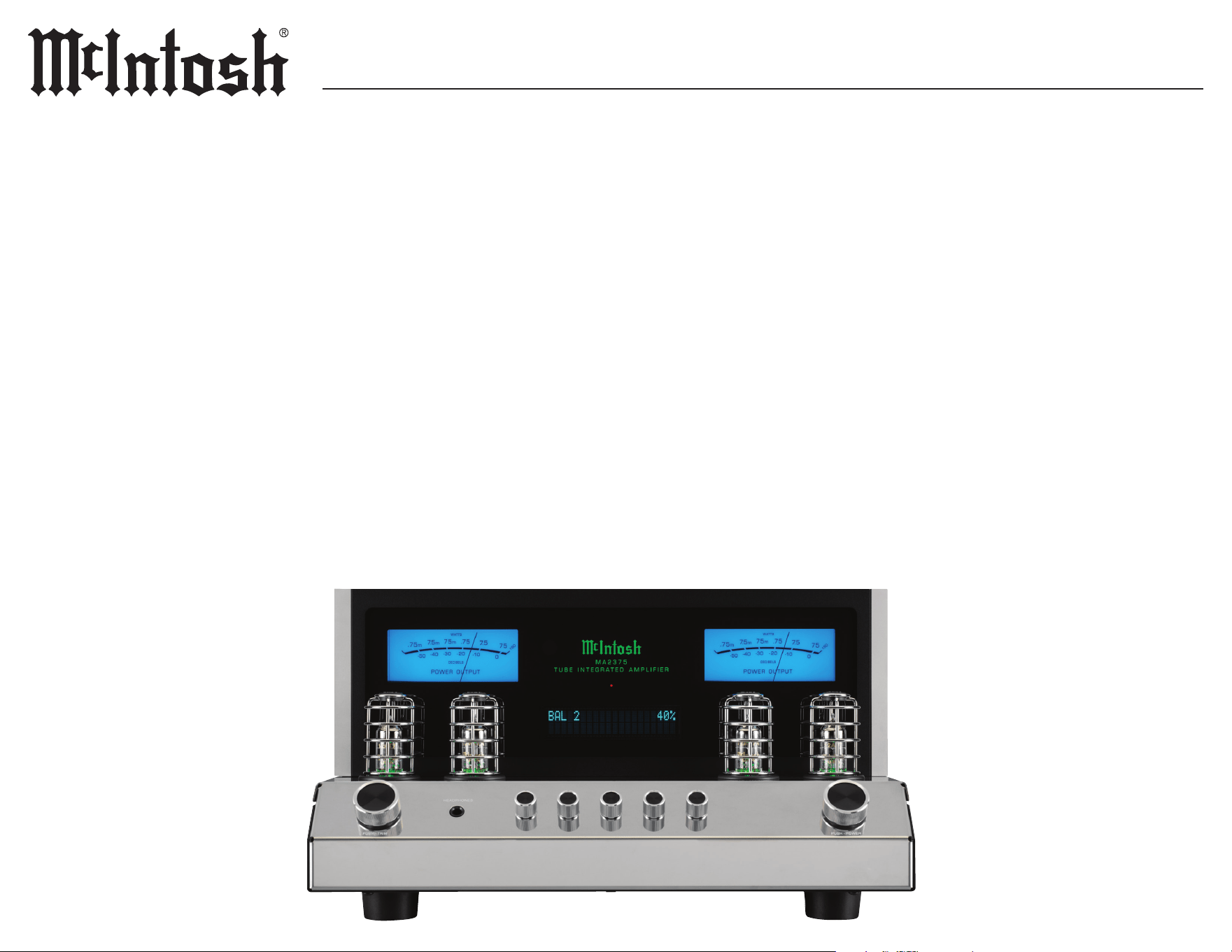
Front Foam Removal
MA2375 UN-PACK V3 PAGE 1
1. Remove Small Cages (4)
HEADPHO NES
PUSH - TRIM PUSH - POWER
M A 2 3 7 5
T U B E I N T E G R A T E D A M P L I F I E R
USB 35%
DSD512
Front
Foam Insert
3. Install Small Cages (4)
HEADPHO NES
PUSH - TRIM PUSH - POWER
M A 2 3 7 5
T U B E I N T E G R A T E D A M P L I F I E R
BAL 1 35%
HEADPHO NES
PUSH - TRIM PUSH - POWER
M A 2 3 7 5
T U B E I N T E G R A T E D A M P L I F I E R
BAL 1 35%
2. Remove Foam Insert
HEADPHO NES
PUSH - TRIM PUSH - POWER
M A 2 3 7 5
T U B E I N T E G R A T E D A M P L I F I E R
BAL 1 35%
Front
Foam Insert
To prevent damage during shipping, there are foam inserts surrounding both the front and rear vacuum tubes of the MA2375.
Both foam inserts must be removed from the MA2375, and all protective cages installed before connecting AC power.
Failure to do so is a re hazard and can result in damage to the MA2375, and the surrounding environment.
To remove the foam inserts and install the protective cages, perform the following steps:
4
FUSE
PUSH
LEFT OUTPUT 1
RS232
EXTERNAL
IR
1 2 TRIGGER PASSTHRU
SERVICE
CONTROL DATA PORTS POWER CONTROL
PORT
R L GND
RIGHT OUTPUT 1
1 R 1 L 2 R 2 L
BALANCED INPUTS UNBALANCED INPUTS
1 2
3
OUTPUTS
OUT 2 SUB
R
L
CAUTION
RISK OF ELECTRIC SHOCK
DO NOT OPEN
SERIAL
NUMBER
McINTOSH LABORATORY, INC. BINGHAMTON, NY
HANDCRAFTED IN USA WITH US AND IMPORTED PARTS
MA2375 TUBE INTEGRATED A MPLIFIER
FUSE
PUSH
LEFT OUTPUT 1
RS232
EXTERNAL
IR
1 2 TRIGGER PASSTHRU
SERVICE
CONTROL DATA PORTS POWER CONTROL PHONO INPUT
PORT
R L GND
RIGHT OUTPUT 1
1 R 1 L 2 R 2 L
BALANCED INPUTS UNBALANCED INPUTS
1 2
3
OUTPUTS
OUT 2 SUB
R
L
CAUTION
RISK OF ELECTRIC SHOCK
DO NOT OPEN
SERIAL
NUMBER
McINTOSH LABORATORY, INC. BINGHAMTON, NY
HANDCRAFTED IN USA WITH US AND IMPORTED PARTS
MA2375 TUBE INTEGRATED A MPLIFIER
PHONO INPUT
PHONO INPUT
PHONO INPUT
PHONO INPUT
MA2375 Un Pack V3 PAGE 2.ai
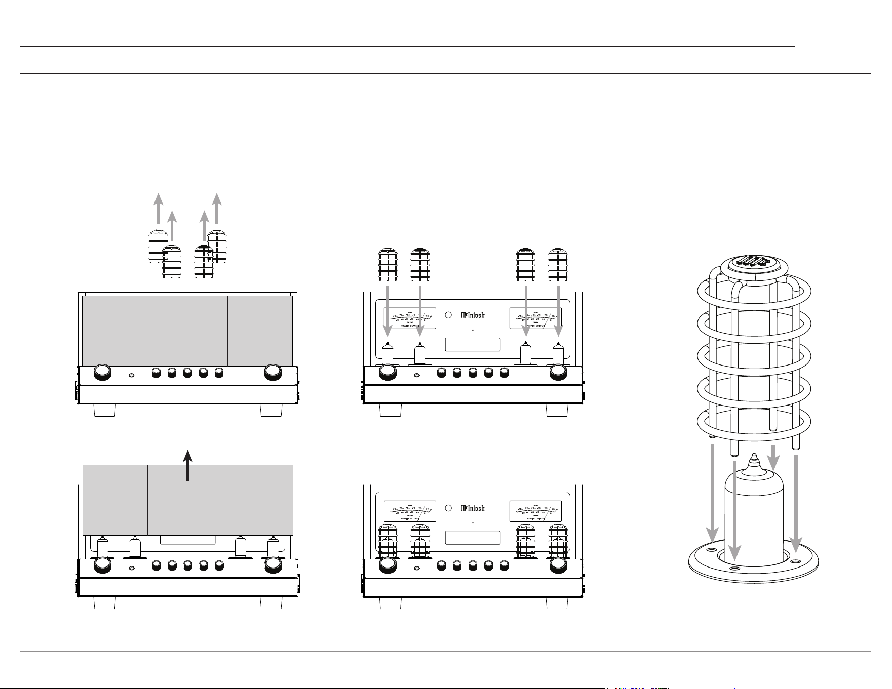
4. Replace Large Cage
3. Remove Foam Insert
Rear Foam Insert
2. Remove Large Cage
Rear Foam Insert
5. Replace Screws (2) & Tags (2)
1. Remove Screws (2) & Tags (2)
V
5
R - KT
88
V
6
R - KT
88
V
6
L - KT
88
V
5
L - KT
88
V
3
R -
12
AT
7
V
3
L -
12
AT
7
V
4
L -
12
AT
7
V
4
R -
12
AT
7
V
2
R -
12
AT
7
V
1
R -
12
AX
7
AV
2
L -
12
AT
7
V
1
L -
12
AX
7
A
Total Harmonic Distortion
0.5% max with both channels operating
from 250 milliwatts to rated power
20Hz to 20,000Hz
Sensitivity (for rated output)
Unbalanced - 250mV
Balanced - 500mV
Phono - 2.5mV
Dynamic Headroom
1.2 dB
Power Output
Minimum sine wave continuous average power output
per channel with both channels operating is:
75W - 4 Ω load
75W - 8 Ω load
75W - 16 Ω load
Signal to Noise Ratio (A-W eighted)
Unbalanced - 93dB below rated power output
Balanced - 93dB below rated power output
Phono - 82dB below 5mV input
Frequency Response
+0, -0.5dB from 20Hz to 20,000Hz
+0, -3dB from 10Hz to 100,000Hz
P
O
W
E
R
T
R
A
N
S
F
O
R
M
E
R
BL
K
B
L
U
G
R
Y
V
I
O
G
R
N
W
H
T
P
R
I
1
P
R
I
2
R
E
D
Y
E
L
R
E
D
S
E
C
1
H
I
G
H
V
O
L
T
A
G
E
B
L
U
G
R
N
B
L
U
S
E
C
2
T
U
B
E
H
E
A
T
E
R
S
R
E
D
Y
E
L
R
E
D
S
E
C
3
L
O
W
V
O
LT
A
G
E
U
N
I
T
Y
C
O
U
P
L
E
D
O
U
T
P
U
T
T
R
A
N
S
F
O
R
M
E
R
P
O
W
E
R
7
5
W
A
T
T
S
F
R
E
Q
U
E
N
C
Y
1
5
H
z
t
o
1
0
0
k
H
z
B
L
U
1
6
Ω
Y
E
L
8
Ω
R
E
D
4
Ω
B
L
K
C
O
M
V
I
O
B
R
N
O
R
N
W
H
T
W
H
T
W
H
T
O
R
N
B
R
N
V
I
O
U
N
I
T
Y
C
O
U
P
L
E
D
O
U
T
P
U
T
T
R
A
N
S
F
O
R
M
E
R
P
O
W
E
R
7
5
W
A
T
T
S
F
R
E
Q
U
E
N
C
Y
1
5
H
z
t
o
1
0
0
k
H
z
B
L
U
1
6
Ω
Y
E
L
8
Ω
R
E
D
4
Ω
B
L
K
C
O
M
V
I
O
B
R
N
O
R
N
W
H
T
W
H
T
W
H
T
O
R
N
B
R
N
V
I
O
T
C
O
O
R
N
O
R
N
VOLUME
INPUT
HEADPHO NES 30 125 500 2k 10k
Rear Foam Removal
5
MA2375
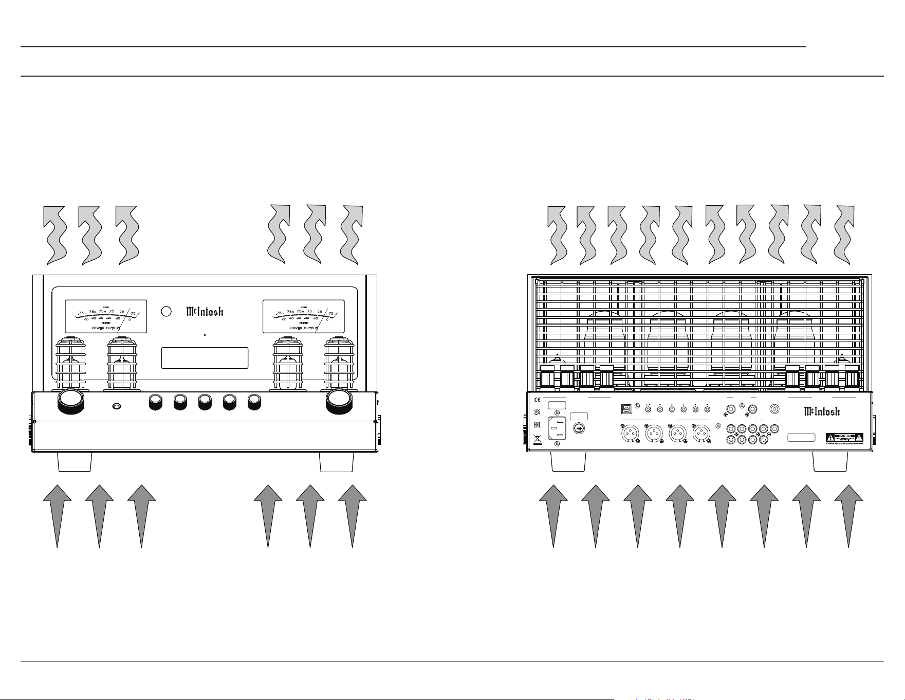
The MA2375 should be installed upright on a solid surface. Adequate ventilation will aid in a long, trouble-free life for the MA2375.
Ensure proper airow by allowing at least 19 in (48.3 cm) above the unit, and 6 in (15.2 cm) for the front, rear, and sides.
Do not remove the feet, they ensure adequate airow beneath the MA2375.
There must be openings for cool air to enter (below), and warm air to escape (above) the MA2375.
Ventilation
HEADP HONES
PUSH - TR IM PUSH - PO WER
M A 2 3 7 5
T U B E I N T E G R A T E D A M P L I F I E R
BAL 1 35%
MA2375 Ventilation Page.ai
FUSE
PUSH
LEFT OUTPUT 1
RS232
EXTERNAL
IR
1 2 TRIGGER PASSTHRU
SERVICE
CONTROL DATA PORTS POWER CONTROL PHONO INPUT
PORT
R L GND
RIGHT OUTPUT 1
1 R 1 L 2 R 2 L
BALANCED INPUTS UNBALANCED INPUTS
1 2
3
OUTPUTS
OUT 2 SUB
R
L
CAUTION
RISK OF ELECTRIC SHOCK
DO NOT OPEN
SERIAL
NUMBER
McINTOSH LABORATORY, INC. BINGHAMTON, NY
HANDCRAFTED IN USA WITH US AND IMPORTED PARTS
MA2375 TUBE INTEGRATED AMPLIFIER
Warm Air
Cool Air
6
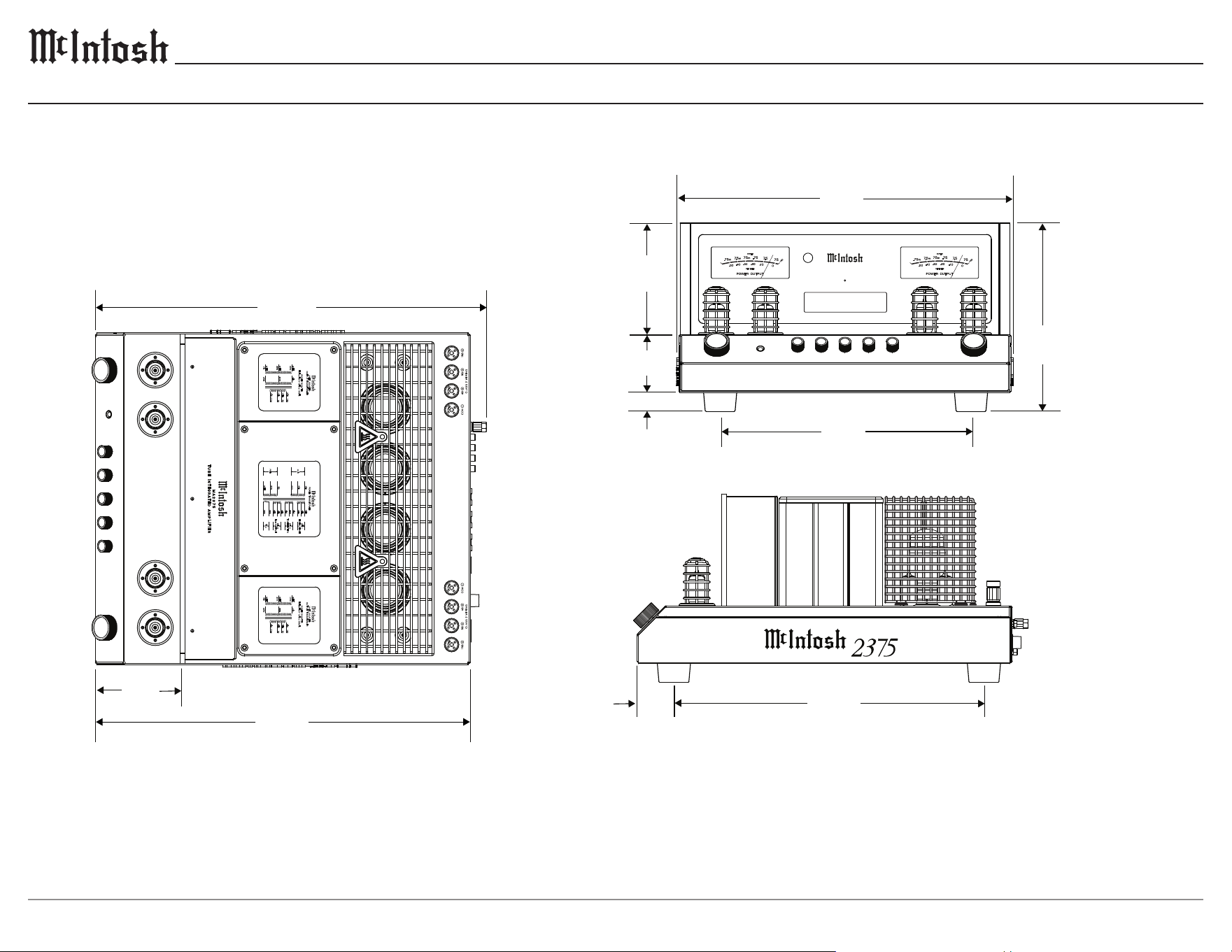
Dimensions
25.2 cm
45.2cm
5.1 cm
41.6 cm
HEADPHO NES
PUSH - TRIM PUSH - POWE R
M A 2 3 7 5
T U B E I N T E G R AT E D A M P L I F I E R
BAL 1 35%
50.3cm
V
5
R - KT
88
V
6
R - KT
88
V
6
L - KT
88
V
5
L - KT
88
V
3
R -
12
AT
7
V
3
L -
12
AT
7
V
4
L -
12
AT
7
V
4
R -
12
AT
7
V
2
R -
12
AT
7
V
1
R -
12
AX
7
AV
2
L -
12
AT
7
V
1
L -
12
AX
7
A
Total Harmonic Distortion
0.5% max with both channels operating
from 250 milliwatts to rated power
20Hz to 20,000Hz
Sensitivity (for rated output)
Unbalanced - 250mV
Balanced - 500mV
Phono - 2.5mV
Dynamic Headroom
1.2 dB
Power Output
Minimum sine wave continuous average power output
per channel with both channels operating is:
75W - 4 Ω load
75W - 8 Ω load
75W - 16 Ω load
Signal to Noise Ratio (A-W eighted)
Unbalanced - 93dB below rated power output
Balanced - 93dB below rated power output
Phono - 82dB below 5mV input
Frequency Response
+0, -0.5dB from 20Hz to 20,000Hz
+0, -3dB from 10Hz to 100,000Hz
POWER TRANSFORMER
BLK
BLU
GRY
VIO
GRN
WHT
PRI 1
PRI 2
RED
YEL
RED
SEC 1
HIGH VOLTAGE
BLU
GRN
BLU
SEC 2
TUBE HEATERS
RED
YEL
RED
SEC 3
LOW VOLTAGE
UNITY COUPLED
O
UTPUT TRANSFORMER
POWER 75 WATTS
FREQUENCY 15Hz to 100kHz
BLU
16Ω
YEL
8Ω
RED 4Ω
BLK
COM
VIO
BRN
ORN
WHT
WHT
WHT
ORN
BRN
VIO
UNITY COUPLED
O
UTPUT TRANSFORMER
POWER 75 WATTS
FREQUENCY 15Hz to 100kHz
BLU
16Ω
YEL
8Ω
RED 4Ω
BLK
COM
VIO
BRN
ORN
WHT
WHT
WHT
ORN
BRN
VIO
TCO
ORN
ORN
VOLUM E
INPUT
HEADPH ONES 30 125 500 2k 10k
MA2375 DIM PG - 6/2/25
7.8 cm
33.7 cm
14.9 cm
2.5 cm
51.9cm
11.3 cm
17 13⁄16”
5 7⁄8”
3 1⁄16”
1”
13 1⁄4”
9 15⁄16”
16 3⁄8”
2”
19 13⁄16”
4 7⁄16”
20 7⁄16”
7
MA2375
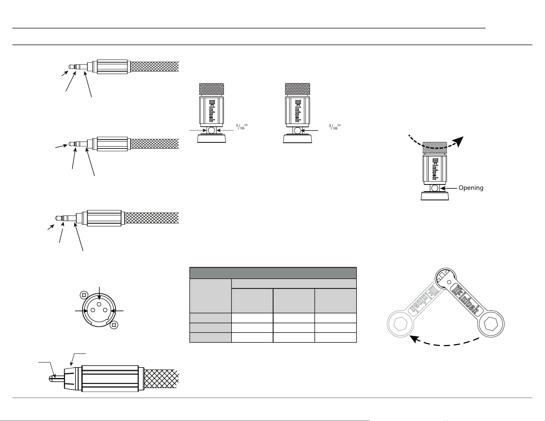
Connectors and Cables
Output Terminals
Loudspeaker cables should be terminated on the
ends to securely t into the terminals according
to the dimensions below.
7.9 mm
Ø
4.8 mm
Loudspeaker Impedance
The MA2375 has four output terminals per
channel, COM, +4 ohm, +8 ohm, and +16 ohm.
Based on the specications of your loudspeaker,
determine the best set of terminals to use. For
a speaker whose impedance falls between two
choices, use the lower impedance terminal.
Loudspeaker Cables
When connecting loudspeakers to the MA2375, it
is very important to use cables of adequate size.
The size is specied in AWG (American Wire
Gauge). The smaller the gauge number, the larger
the wire size.
Loudspeaker Cable Wire Gauge Guide
Loudspeaker
Impedance
Cable Distance
25 feet
(7.62 meters)
or less
50 feet
(15.24 meters)
or less
100 feet
(30.48 meters)
or less
4 ohms 12AWG 10AWG 8AWG
8 ohms 14AWG 12AWG 10AWG
16 ohms 16AWG 14AWG 12AWG
Loudspeaker Cable Connections
When connecting loudspeaker cables to the
MA2375 output terminals,
1. Make sure AC power is disconnected.
2. Rotate the top of the output terminal counter-
clockwise until an opening appears.
3. Insert the loudspeaker cable into the
output terminal. Proper polarity must be
maintained for all connections. (+/-)
4. Rotate the top of the output terminal clock-
wise until it is nger-tight.
5. Place the McIntosh wrench over the top of the
output terminal, and rotate the output terminal
clockwise one quarter of a turn (90°). Do not
over tighten.
n
Meter
Illuminatio
Control
Ground
Power
Control
N/C
Data
Ground
RXD
(Data Received
by MA2375)
TXD (Data
Transmitted
by MA2375)
2
1
3
Ground
(-) Signal
+) Signal
(
Signal
Ground
Power Control Connectors
RS232-C Data Port Cable
Data Port / IR Connectors
XLR Connectors
RCA Connectors
Ground
8
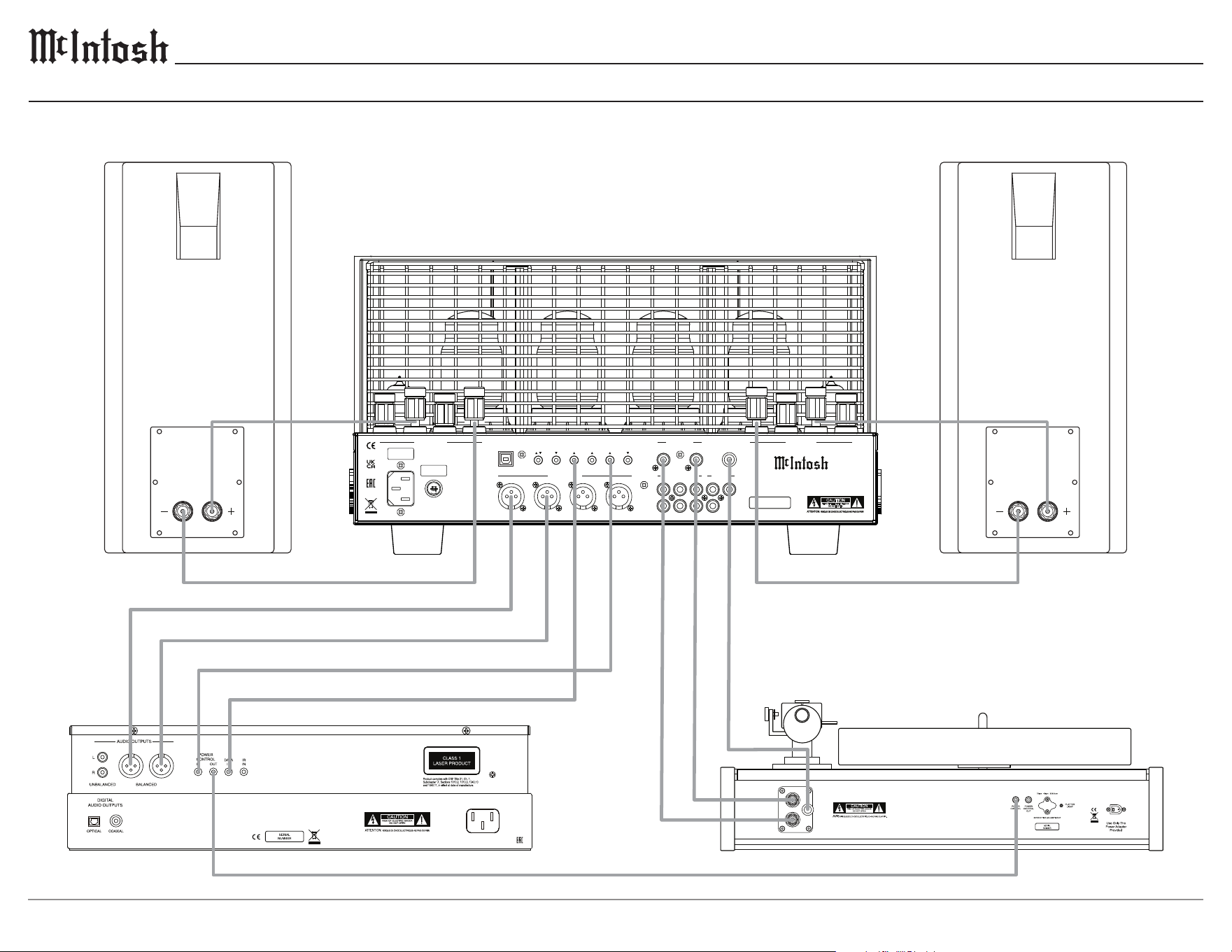
Connection Diagram
This connection diagram represents a typical 2-channel setup using the MA2375, disc player, turntable, and a pair of loudspeakers.
Connect the components of the desired system in a similar manner.
FUSE
PUSH
LEFT OUTPUT 1
RS232
EXTERNAL
IR
1 2 TRIGGER PASSTHRU
SERVICE
CONTROL DATA PORTS POWER CONTROL PHONO INPUT
PORT
R L GND
RIGHT OUTPUT 1
1 R 1 L 2 R 2 L
BALANCED INPUTS UNBALANCED INPUTS
1 2
3
OUTPUTS
OUT 2 SUB
R
L
CAUTION
RISK OF ELECTRIC SHOCK
DO NOT OPEN
SERIAL
NUMBER
McINTOSH LABORATORY, INC. BINGHAMTON, NY
HANDCRAFTED IN USA WITH US AND IMPORTED PARTS
MA2375 TUBE INTEGRATED AMPLIFIER
MA2375 CONNECTION PAGE.ai
9
MA2375
Remote Control Operation
CABLE
TV
AUX
1
2
3
4
5
6
7
8
9
0
AM PRESET
FM
INPUT
VOL
PRESET SEEK PRESET
HRO85
BAND
SELECT
AM
OUTPUT2
OUTPUT 1
LEVEL UP
MENU
INFO
LEVEL DN
TRIM
GUIDE
EXIT
MODE
SETUP
1
13 14
15
16
17
18
19
21
20
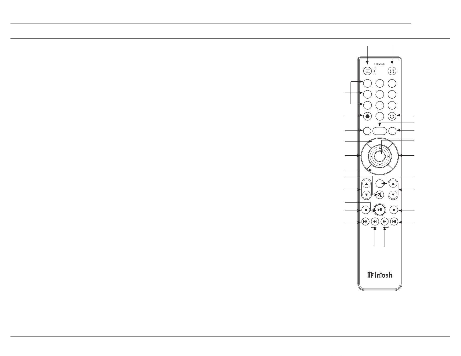
1. Switch Device1 jumps through dierent
devices for remote operation. The selected
device is indicated by the LED's to the right of
the button.
2. Numbers1 select tuner presets, manually
enters disc tracks and radio stations, and
performs various other operations.
3.
SETUP accesses additional functions of the
AM and FM buttons, working as a "shift"
key to access OUTPUT 1 and OUTPUT 2
functions.
(Note: Cannot be used to enter the MA2375's Setup menu.)
4. A M Tu ner1/OUTPUT 1 accesses AM
Tuner, or toggles Output 1 if pressed after the
SETUP button.
5. LEVEL UP/MENU accesses Trim functions
in the Settings menu of compatible devices.
6. TRIM/GUIDE enters Trim menu, and opens
Guide on compatible devices.
7. INFO/LEVEL DOWN accesses Trim
functions in the Iettings menu of compatible
devices.
8. Mute: stops all audio playback.
9. INPUT changes and selects dierent inputs.
10. Play1/Pause1 halts playback of active media,
and resumes upon pressing the button again.
11. Stop1 cancels playback, and resets progress in
the active media.
12. Previous1/Previous PRESET1 goes back to
the previously selected media, and navigates
to a previous tuner preset.
13. Fast Reverse1/SEEK Down1 navigates
backward through the active media, and
adjusts the Tuner downward.
22
23
24
14. Fast Forward1/SEEK Up1 navigates forward
through the active media, and adjusts the
tuner upwards.
15. Next1/Next PRESET1 moves forward to the
next media selection, and navigates to a later
tuner preset.
16. Record1 records actively playing media.
17. VOL adjusts the volume.
18. BAND1 changes the band on the connected
tuner, and selects certain options on various
McIntosh models.
19. MODE/EXIT exits the Trim menu, and
displays information and options.
20. SELECT1 picks the highlighted option where
applicable.
21. FM Tuner1/OUTPUT 2 accesses FM Tuner,
or toggles Output 2 if pressed after the
SETUP button.
22. PRESET1 selects a stored preset when press-
ing PRESET followed by the number (0-9)
associated with the desired preset.
23. Power O turns o the selected device.
24. Power On turns on the selected device.
Additional Discrete Commands
Additional discrete commands for external control
systems are available for toggling power, and
selecting audio inputs.
These additional commands can be accessed
using an optional McIntosh HR093 service remote
control.
Contact McIntosh Technical Assistance, or your
dealer for more information.
Note1: The included McIntosh HR085 remote control has
buttons used to control multiple devices. While operating the
MA2375 with the remote, nothing will happen when pressing
buttons that activate features not present on the MA2375.
2
3
4
5
6
7
8
9
10
11
12
10
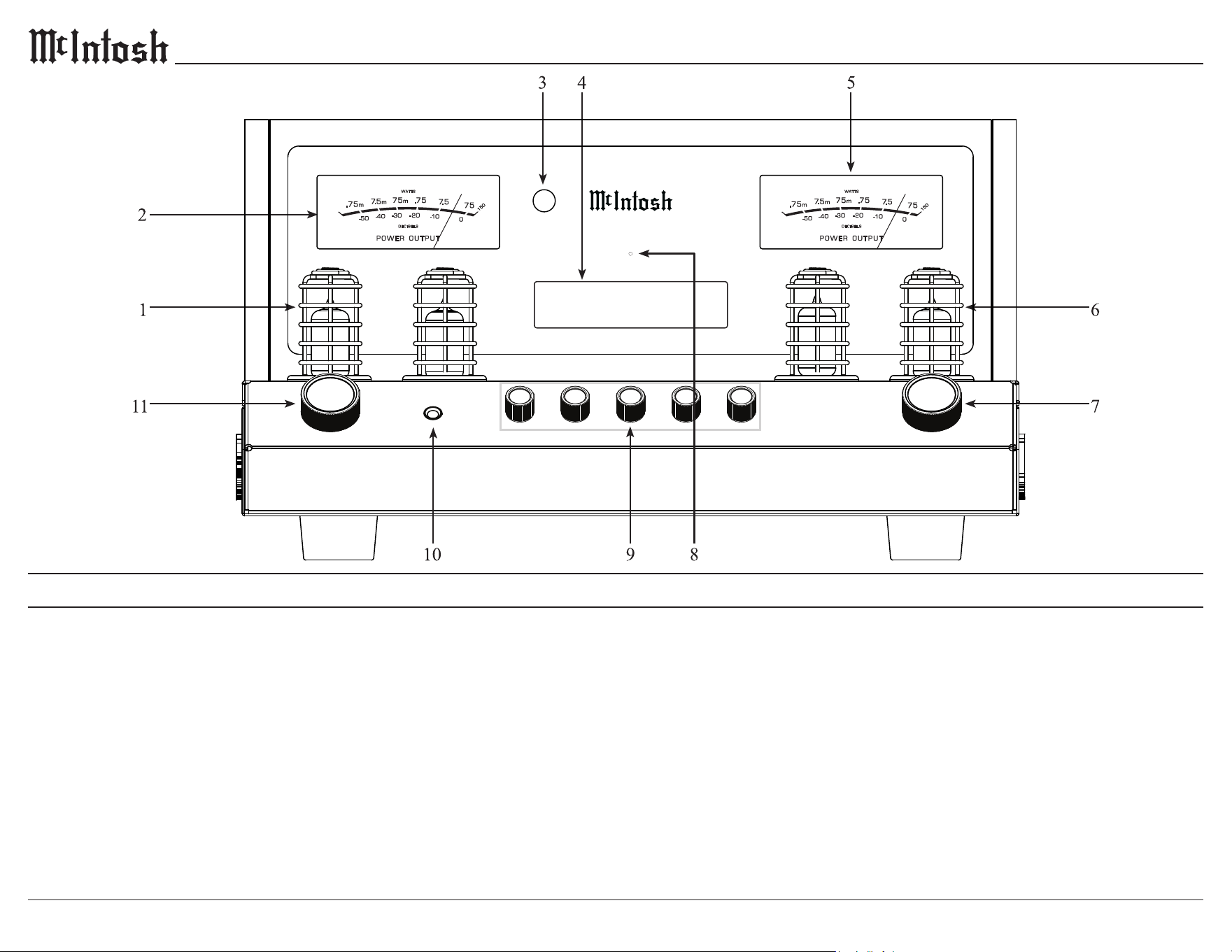
1. Left Preamplifier Vacuum Tubes
Orange - Warmup mode/Left Power Guard
Green (or off) - Normal operation
2. Left POWER OUTPUT Meter indicates
the left channel output level in WATTS and
DECIBELS.
3. IR Sensor receives commands from a remote
control.
4. Information Display indicates input selec-
tion, volume setting, and the Trim, and Setup
menus.
Front Panel
5. Right POWER OUTPUT Meter indicates
the right channel output level in WATTS and
DECIBELS.
6. Right Preamplifier Vacuum Tubes
Orange - Warmup mode/Right Power Guard
Green (or off) - Normal operation
7. VOLUME Knob allows adjustment of the
listening level for both channels and is used
to change various Trim and Setup functions.
Push to turn the MA2375 on/off.
8. Standby LED indicates AC power is present,
allowing the MA2375 to be turned on. If
flashing, the sentry monitor protection circuits
have activated.
9. Equalizer Knobs increase or decrease the
volume levels at the center frequencies of
30 Hz, 125 Hz, 500 Hz, 2k Hz, and 10k Hz.
10. HEADPHONE connection for private
listening.
11. INPUT Knob is used to select a source for
listening. Push to enter the TRIM menu. Push
and hold to enter the SETUP menu.
MA2375 INT AMP FRONT X8
HEA DPH ONE S
PUS H - TRI M PUS H - POW ER
M A 2 3 7 5
T U B E I N T E G R A T E D A M P L I F I E R
BAL 1 35%
11
MA2375
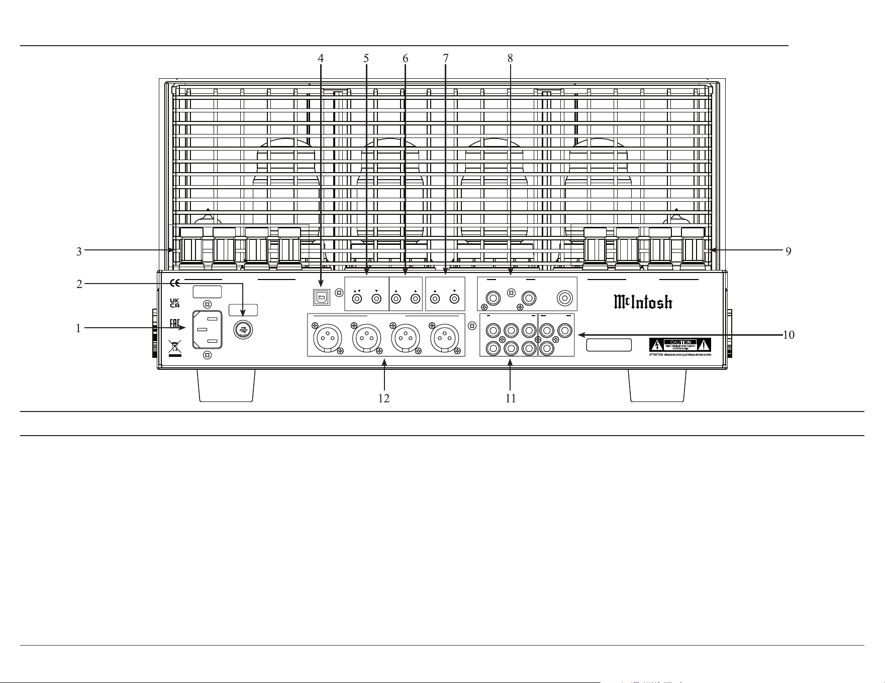
1. AC Input connects the MA2375 power cord
to a live AC outlet. Refer to the rear panel for
voltage and current requirements.
2. Main Fuse Holder, refer to the rear panel to
determine the correct fuse size and rating.
3. RIGHT OUTPUT 1 connections for a 4, 8, or
16 ohm loudspeaker.
4. SERVICE PORT is used to update the
MA2375 rmware.
Rear Panel
5. EXTERNAL CONTROL connections allow
for control of the MA2375 from either a
RS232 third-party control system, or a remote
IR Sensor.
6. DATA PORTS retransmit remote control
signals to source components.
7. POWER CONTROL connections allow
for turn on/o control of other McIntosh
components.
TRIGGER sends a turn on/o signal to
another component.
PASST H RU receives a turn on/o signal
from a home theater processor.
8. PHONO INPUT accepts phono signals and a
GND connection from a turntable.
9. LEFT OUTPUT 1 connections for a 4, 8, or
16 ohm loudspeaker.
10. Preamplier OUTPUTS can be used to drive
additional ampliers. OUT 2 provides a full
range stereo output, and SUB provides a full
range mono output.
11. UNBALANCED INPUTS 1, 2, and 3 accept
line level unbalanced signals.
12. BALANCED INPUTS 1 and 2 accept line-
level balanced signals.
FUSE
PUSH
LEFT OUTPUT 1
RS232
EXTERNAL
IR
1 2 TRIGGER PASSTHRU
SERVICE
CONTROL DATA PORTS POWER CONTROL PHONO INPUT
PORT
R L GND
RIGHT OUTPUT 1
1 R 1 L 2 R 2 L
BALANCED INPUTS UNBALANCED INPUTS
1 2
3
OUTPUTS
OUT 2 SUB
R
L
CAUTION
RISK OF ELECTRIC SHOCK
DO NOT OPEN
SERIAL
NUMBER
McINTOSH LABORATORY, INC. BINGHAMTON, NY
HANDCRAFTED IN USA WITH US AND IMPORTED PARTS
MA2375 TUBE INTEGRATED AMPLIFIER
MA2375 REAR VIEW w_cage x8.ai
12
Trim Function Adjustment
The MA2375 has a variety of dierent trim
settings that customize various audio, and lighting
options. Selection and adjustment of all trim
functions may be performed by pressing the
front panel INPUT control, then rotating it to
select the desired trim function for the current
input. Use the VOLUME knob on the front
panel to adjust the setting. The TRIM button
on the remote control may be used to move
through each trim function, while the LEVEL
UP/LEVEL DN buttons control the selected
function
.
With each Trim menu, the information
display returns to indicate the input selection and
volume level after approximately 10 seconds.
Balance
Listening balance varies with dierent program
sources, room acoustics, and listening positions
relative to the loudspeakers. Use the balance to
achieve equal volume levels in each loudspeaker.
L BALANCE R >
||
L BALANCE R >
½½½½½½½
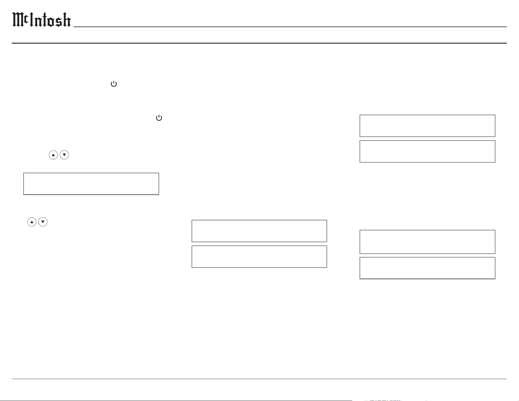
Power On and Off
The red LED above the information display
indicates the MA2375 is in Standby mode. To
switch on the MA2375, press the VOLUME knob
on the front panel, or the green
button on the
remote control. Upon turning on the unit, there
will be a brief “Warmup” period before the unit is
ready to use. To switch o the MA2375, press the
VOLUME knob on the front panel, or the red
button on the remote control.
Input Selection
Rotate the INPUT knob on the front panel, or use
the INPUT
buttons on the remote control
to select the desired input.
BAL 1 15%
Volume Control
Rotate the front panel VOLUME knob, or use the
VOL
buttons on the remote control to set
the desired listening level.
Basic Operation
Input Trim Level
Source components can have slightly dierent
volume levels, resulting in the need to readjust the
MA2375 volume when switching between dier-
ent sources. The MA2375 allows the adjustment
of levels for each of the input sources for the same
relative volume. Adjusting this setting changes the
trim for the currently selected input.
< INPUT TRIM >
< 0.0 dB >
< INPUT TRIM >
< +6.0 dB
Equalizer Mode
The built-in 5-band equalizer provides more
precise adjustment of sound than standard bass
and treble controls. By default, the equalizer is
On for all input sources. Any input source may be
assigned to have the equalizer On, or O when
selected.
< EQUALIZER >
< On
< EQUALIZER >
Off >
13
MA2375
Mono/Stereo Mode
Stereo allows separate left and right audio signals
to be sent to their respective speaker. Mono sums
the left and right audio signals before sending the
same signal to each speaker. By default, the Stereo
Mode is active for all inputs, however, any input
source may be assigned to the Mono Mode of
operation.
< MONO / STEREO >
______
< MONO / STEREO >
____
OUTPUT 1 & 2
The OUTPUT 1 setting is for loudspeakers
connected to the power amplier circuitry of the
MA2375. The OUTPUT 2 setting is for an exter-
nal power amplier connected to the MA2375 rear
panel OUTPUT 2 jacks. Select the appropriate
setting for OUTPUT 1 and OUTPUT 2 settings,
either On or O.
< OUTPUT 1 >
Off >
< OUTPUT 1 >
< On
Sub Out
SUB OUT is designated for connecting subwoofers
to the MA2375. By default, the SUB OUT setting is
enabled.
< SUB OUT >
Off >
< SUB OUT >
< On
Meter Illumination
The meter illumination of the MA2375 may be
switched On or O as desired.
< METER LIGHTS >
< On
< METER LIGHTS >
Off >
Tube Lights
The MA2375 vacuum tube illumination may be
switched On or O.
< TUBE LIGHTS >
< On
< TUBE LIGHTS >
Off >
Display Auto Off
The information display of the MA2375 can be set
to automatically turn o after a select period of
time.
< DISPLAY AUTO OFF >
Disabled >
< DISPLAY AUTO OFF >
< 5 Min
Information Display Brightness
The brightness level of MA2375 information
display can be adjusted from bright to dim.
< BRIGHTNESS >
½½½½½½½½½½½½½½½
< BRIGHTNESS >
½½½½½½½½½½½½½½½½½½½½
Headphone HXD
The Headphone HXD feature on the MA2375
appears when headphones are plugged into the
front panel of the unit. The Headphone Crossfeed
Director Circuitry can be turned On to create a
sound-stage eect, making audio sound like it's
coming from loudspeakers in front of the user.
< HEADPHONE HXD
< On
< HEADPHONE HXD
Off >
14
Phono Input Connection and Setup
Connect the turntables left/right audio outputs and
ground connection to the MA2375 phono input as
shown in the Connection Diagram on page 8.
Determine the type of phono cartridge the
turntable uses, the majority of phono cartridges
fall into one of three categories.
Moving Magnet: The most common phono
cartridge. Requires less gain than a moving coil
cartridge, and a specic capacitive load.
Low Output Moving Coil: Requires the most
gain compared to other cartridges, and a specic
resistive load.
High Output Moving Coil: Requires more gain
than a moving magnet cartridge, but less gain
than a low output moving coil cartridge. Requires
a specic resistive load.
Turntable Setup
Phono Trim Functions
When the phono input is selected, three extra
settings will be available in the Trim menu —
capacitance, resistance, and gain. When changing
these settings, keep the turntables cartridge type
in mind. It is important for the phono cartridge
to be connected to a phono preamp with an input
impedance (resistance and capacitance) the same
as the cartridge load specications. In addition,
the gain must be set according to the output
capability of the cartridge.
Capacitance
The capacitance setting adjusts the capacitive load
the phono cartridge sees to optimize the phono
preamp to the cartridge.
< CAPACITANCE >
50pF >
Resistance
The resistance setting adjusts the resistive load
the phono cartridge sees to optimize the phono
preamp to the cartridge.
< RESISTANCE >
< 47k
Ʊ
Gain
The gain setting controls how much the low level
phono signal is amplied. The higher the dB, the
more amplication.
< PHONO GAIN
40dB >
Turntables With Built-In Preamps
Some turntables have built-in phono preamps,
and are designed to be used with components
without phono inputs. Many turntables with
built-in preamps have a switch on the rear panel,
or under the platter that allows the built-in preamp
to be bypassed. If the built-in preamp cannot be
bypassed, do not connect it to the phono inputs
on the MA2375. Instead, connect the turntables
left/right audio outputs to one of the unbalanced
inputs.
One exception to this rule is if the turntable must
be placed more than 10 ft (3 m) from the MA2375.
Low level signals may pick up hum and noise if
they travel down a longer audio cable. In such
cases, use the preamp in the turntable and connect
the turntable to an unbalanced input on the
preamp, not the phono input.

15
MA2375
Moving Magnet
CAPACITANCE: Many modern phono cartridg-
es are insensitive to changes in capacitance, and
changing the setting may not alter the sound
being output. Regardless, some moving magnet
cartridges work best with a specic capacitive
load. Check the specications of the cartridge to
determine its ideal capacitance. For example, if
the cartridge specication says 300 pF is ideal, the
capacitance should be set at 300 pF or lower.
A lower setting will take the inherent capacitance
in audio cables, which can add to the load, into
account.
RESISTANCE: Almost all moving magnet
phono cartridges are designed to work best into
a resistance of 47k ohms. Unless a cartridge’s
specications call for a dierent setting, set the
preamp to provide 47k ohms of resistance.
GAIN: When using a moving magnet cartridge,
start with the gain of the preamp at 40 dB. If the
volume from the turntable is much lower than
that of other sources in a system, the gain can be
increased to 46 dB.
INPUT LEVEL TRIM: It’s common for the
volume level from a turntable to be lower than
other sources, even after setting the phono preamp
gain properly. The input trim adjustment in the
MA2375 can be increased so that the phono input
matches the level of other input sources.
See pages 12 & 13 for Trim menu instructions and options.
Low Output Moving Coil
CAPACITANCE: Low-output moving coil
cartridges have a low output impedance, and are
not sensitive to capacitance. Leave the capacitance
at 50 pF.
RESISTANCE: Most low-output moving coil
phono cartridges are designed to work best in a
resistance between 100 and 400 ohms. Check the
specications of the phono cartridge being used
to determine this. Some listeners may prefer to set
the resistance “by ear” for their preferred sound.
While playing s record with a wide range of
instruments and voices, start with the resistance
at 400 ohms, then decrease the resistance step-
by-step until reaching the preferred sound. This is
best done in the main listening position, using the
remote control to access the Trim menu.
GAIN: When using a low-output moving coil
cartridge, start with the gain of the phono preamp
at 58dB. If the volume from the turntable is much
lower than other sources in the system, the gain
can be increased to 64 dB.
INPUT LEVEL TRIM: It’s common for the
volume level from turntable to be lower than
higher level sources even after setting the preamp
gain properly.
The input trim adjustment in the
MA2375 can be increased so the phono input
matches the levels of other input sources.
See pages 12 & 13 for Trim menu instructions and
options.
High Output Moving Coil
CAPACITANCE: High-output moving coil
cartridges usually have a low output impedance,
and are not sensitive to capacitance. Leave the
capacitance at 50 pF.
RESISTANCE: Most high-output moving coil
phono cartridges are designed to work best with
a resistive load between 750 and 1k ohms. Check
the specications of the cartridge being used
for the ideal resistance setting. Some listeners
may prefer to set the resistance “by ear” for their
preferred sound. While playing s record with
a wide range of instruments and voices, start
with the resistance at 1k ohms, then decrease
the resistance step-by-step until reaching the
preferred sound. This is best done in the main
listening position, using the remote control to
access the Trim menu.
GAIN: When using a high-output moving coil
cartridge, start with the gain of the phono preamp
at 46 dB. If the volume the turntable is much
lower than other sources in a system, the gain can
be increased to 52 dB.
INPUT LEVEL TRIM: It’s common for the
volume level from turntable to be lower than
higher level sources even after setting the preamp
gain properly.
The input trim adjustment in the
MA2375 can be increased so the phono input
matches the levels of other input sources.
See pages 12 & 13 for Trim menu instructions and
options.
16
Input Setup Submenu
Settings Options
Enable O, On
Name
Enable
By default, all inputs are On. Unused inputs can be
turned O so that they do not appear on the display
during input selection. Rotate the VOLUME knob to
turn the selected input On or O.
Rename
Inputs can be renamed to more accurately reect
the source component that it is associated with.
Rotate the INPUT knob so that the display says
“Input: Name, Rename Input” and press the
INPUT knob to begin renaming.
Input: < Name >
Rename Input
A blinking cursor will appear over the selected
character of the input’s name. Rotate the INPUT
knob to select which character to change, and use
the VOLUME knob to change the character. Once
the new name has been entered, hold the INPUT
knob to conrm. Otherwise, a press and release
of the INPUT knob will return the display to the
previous menu without applying the changes.
Settings Options
Product MA2375 - (serial number)
Firmware (current rmware version)
Pa ssT hr u Disabled, BAL 1-2, UNBAL 1-3
Power Auto O, Always On
Factory (restore factory default settings)
Note: Bold options indicate default settings
Product Information
Specic identifying information for the MA2375
is shown in the Product menu.
Firmware
The current rmware version will be displayed here.
PassThru
When the MA2375 is part of a home theater, or
multichannel audio system, the right and left front
channels from an audio/video processor, or surround
decoder can “PassThru” the MA2375 and into its
associated power amplier(s). The PassThru setting
allows selection of the specied MA2375 input to be
used for the right and left front channels.
System: < Passthru >
Disabled >
Power
Auto O: The MA2375 will automatically enter
sleep mode after approximately 20 minutes
without user activity, or an audio signal.
Always On: The MA2375 must be turned o by
pressing the POWER button on the front panel, or
the red
button on the remote control.
System: < Power >
Auto Off >
System Setup SubmenuSetup Menus
Submenus Settings
System Product Information, Firmware,
PassThru, Auto O, Factory Reset
Inputs Enabled, Name
Outputs Output 1, Output 2, Sub Out,
Headphones
Data Ports Port 1, Port 2
External Control Front IR, IR Codes, RS232
Setup Menu Navigation
The McIntosh MA2375 has been factory congured
to allow immediate enjoyment of superb audio
without the need for further adjustments. If changes
must be made to the factory default settings, a
Setup menu is provided to customize the operating
settings using the front panel display.
To access the Setup menu, press and hold the
INPUT knob on the front panel until the informa-
tion display indicates the following:
Setup: Menu Select
System >
Using the INPUT knob, navigate through the
submenus by rotating, and select by pressing the
knob in. Once the desired submenu has been
selected, rotate the INPUT knob to navigate
through the submenu settings. To change the
selected setting, rotate the VOLUME knob. Exit
the Setup menu by rotating the INPUT knob to
Exit selection.
Factory Reset
To reset all adjustable settings to their factory
default, select factory reset. Hold in the INPUT
knob to reset the unit.
System: < Factory >
Hold INPUT to Reset
17
MA2375
Output Setup Submenu Data Ports Setup Submenu
External Control Setup Submenu
Settings Options
Front IR Enabled, Disabled
IR Codes Normal, Alternate
RS232 9600, 19200, 38400, 57600,
115200 Baud
Front IR
The MA2375 front panel sensor, which receives
the signals from the HR085 remote control, can be
Disabled to prevent interference when an external
IR sensor is connected.
Ext Ctrl: Front IR >
< Enabled
Ext Ctrl: Front IR >
Disabled >
IR Codes
The remote control included with the MA2375
utilizes the normal McIntosh control codes. The
second set of control codes the MA2375 will
respond to is referred to as the Alternate Codes.
The Alternate Codes are used when the MA2375
is used in the same location as another McIntosh
preamplier and/or A/V processor. This will prevent
the remote control from aecting the operation of
both units at the same time.
Ext Ctrl: <IR Codes>
Normal >
It is now necessary to change the HR085 remote
control over to the Alternate Codes.
RS232
The MA2375 may be remotely controlled from
other equipment connected to the rear panel
RS232 port. The speed at which the MA2375
communicates (8 bit, no parity, and 1 stop bit)
with other equipment is adjustable from
9,600 Baud (bits per second) to 115,200 Baud.
Ext Ctrl: < RS232 >
< 115200 Baud
Settings Options
Port 1 All Data, BAL 1-2 UNBAL 1-3
Port 2 All Data, BAL 1-2 UNBAL 1-3
Data port connections between the MA2375 and a
McIntosh source component allow basic function
control of the source component using the MA2375
supplied HR085 remote control. By default, the
two data ports are set to send the same data to
the selected source. To dedicate a given data port
for only one source component select the desired
output.
SETUP: Menu Select
< Data Ports >
Data Port: 1 >
< UNBAL 1 >
Settings Options
Output 1 Switched, Unswitched
Output 2 Switched, Unswitched
Sub Out
Switched, Output 1-2, Unswitched
Headphones
Mute All Outputs, Mute No Outputs
Outputs 1 and 2
The output setup menu provides the ability to change
how Output 1, Output 2, Sub Out, and Headphones
function. Each output can be independently cong
-
ured to operate in one of several modes. Each output
is set to Switched by default, which allows toggling
using the OUTPUT 1 and OUTPUT 2 buttons on the
remote control. Output cannot be turned o when
Unswitched.
Output: OUTPUT 1 >
Switched >
Sub Out
Like Outputs 1 and 2, Sub Out is automatically
Switched. Selecting the Output 1 or Output 2
options make Sub Out mirror what is done on
the selected output. For example, if Output 1 is
selected and turned o, Sub Out will follow
.
Output: < SUB OUT >
Switched >
Headphones
By default, the Mute All Outputs setting is
turned on, muting all outputs upon plugging in
headphones unless they are setup as Unswitched.
Selecting the Mute No Outputs option wont turn
o any outputs when headphones are plugged in.
In the unlikely event the controls of the MA2375
stop functioning, the microprocessor can be reset
1. Press and hold in the front panel VOLUME
knob until the standby LED switches o.
2. Release the VOLUME knob, and the MA2375
will switch o.
3. When the STANDBY/ON LED is illuminated
press the VOLUME knob, and the MA2375
will resume normal operation.
Resetting the Microprocessors
18
Input Impedance
Unbalanced: 22kΩ
Balanced: 44kΩ
Phono: 100 - 47kΩ; 50 - 400pF
Maximum Input Signal
Unbalanced: 5 V
Balanced: 10 V
Phono: 80m V*
Voltage Gain
High Level to Output 1: 38 dB (8Ω)
High Level to Output 2: 15 dB
Phono to Output 1: 78 dB (8Ω)*
Phono to Output 2: 55 dB*
Headphone Load Impedance
100 to 600 ohms
Trigger Output
12VDC, 25mA
Specications
*Factory default phono settings.
FTC Power Output Rating
75 watts
Rated Output
Output 1: 75 watts
Output 2: 1.7 V
Sub: 1.7 V
Output 1 Load Impedance
4, 8, or 16Ω
Rated Power Band
20 Hz to 20k Hz
Total Harmonic Distortion
0.5% maximum with both channels operating from 250 milliwatts to rated
power, 20 Hz to 20k Hz
Intermodulation Distortion
0.5% maximum, if the instantaneous peak power output does not exceed
twice the rated power output for any combination of frequencies from
20 Hz to 20k Hz
Dynamic Headroom
1.2 dB
Wide Band Damping Factor
Greater than 22
Frequency Response
+0, -0.5 dB from 20 Hz to 20k Hz
+0, -3 dB from 10 Hz to 50k Hz
Preamplier Output Impedance
100Ω
Sensitivity (for rated output)
Unbalanced: 300m V
Balanced: 600m V
Phono: 3m V*
Signal To Noise Ratio (A-Weighted)
Unbalanced: 95 dB below rated output
Balanced: 95 dB below rated output
Phono: 75 dB below rated output*
Power Requirements
Field AC voltage conversion of the MA2375 is
not possible. The MA2375 is factory congured
for one of the following AC voltages:
100 Volts, 50/60Hz at 4.4 amps
110 Volts, 50/60Hz at 3.6 amps
120 Volts, 50/60Hz at 3.6 amps
220 Volts, 50/60Hz at 2.0 amps
230 Volts, 50/60Hz at 1.8 amps
240 Volts, 50/60Hz at 1.8 amps
Standby: Less than 0.25 watt
Note: Refer to the rear panel of the MA2375
for the correct voltage.
Overall Dimensions
Width: 1713/16 inches / 45.2 cm
Height: 915/16 inches / 25.2 cm
Depth: 207/16 inches / 51.9 cm
Weight
Net: 93 pounds / 42.2 kg
In shipping carton: 103 pounds / 46.7 kg
Shipping Carton Dimensions
Width: 231/4 inches / 59.1 cm
Depth: 251/4 inches / 64.1 cm
Height: 141/2 inches / 36.8 cm
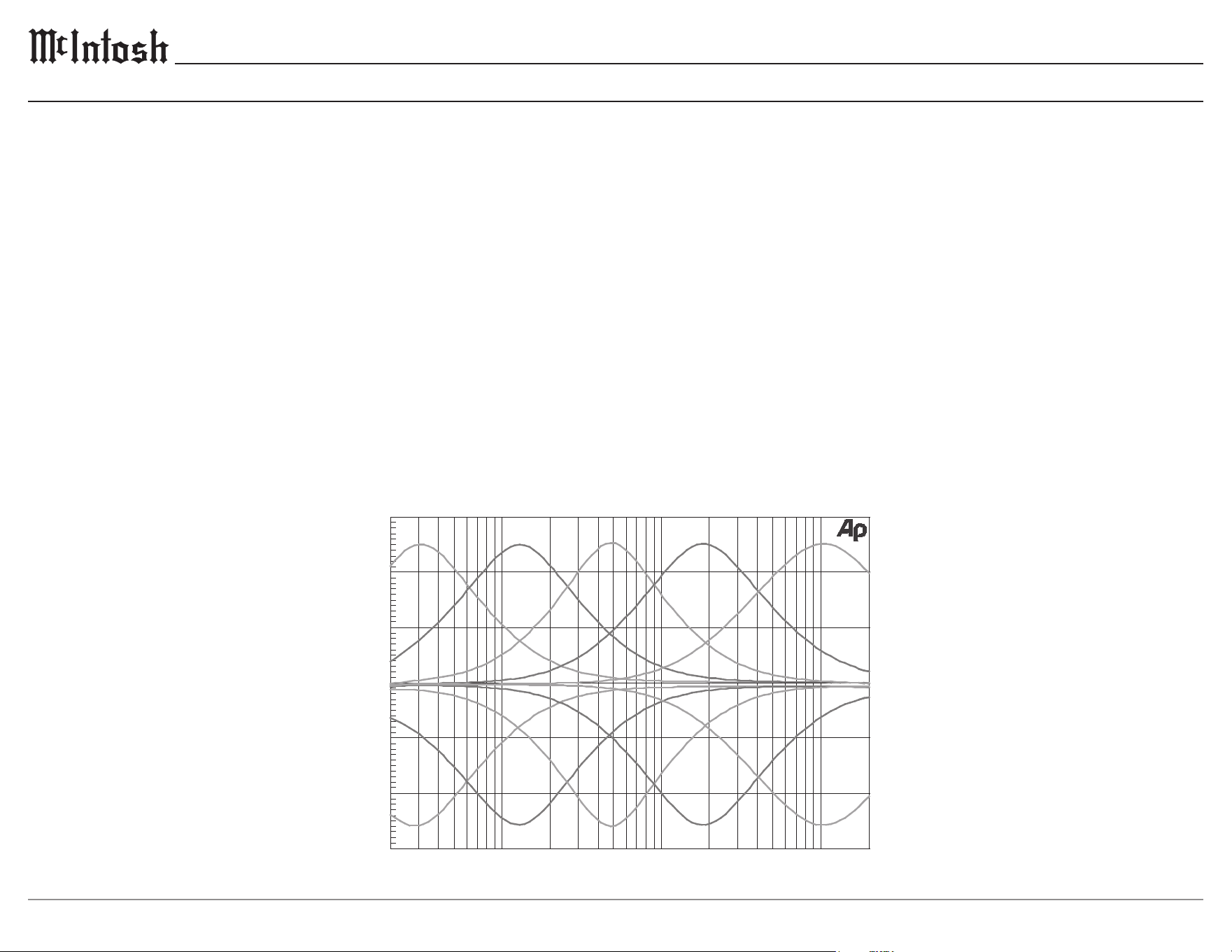
-15
20 50 100 200 500 1k
2k 5k 10k 20k
FREQUENCY IN HERTZ
0
- 5
A
M
P
L
I
T
U
D
E
I
N
D
E
C
I
B
E
L
S
-10
+ 5
+10
+15
Equalizer Controls
19
MA2375
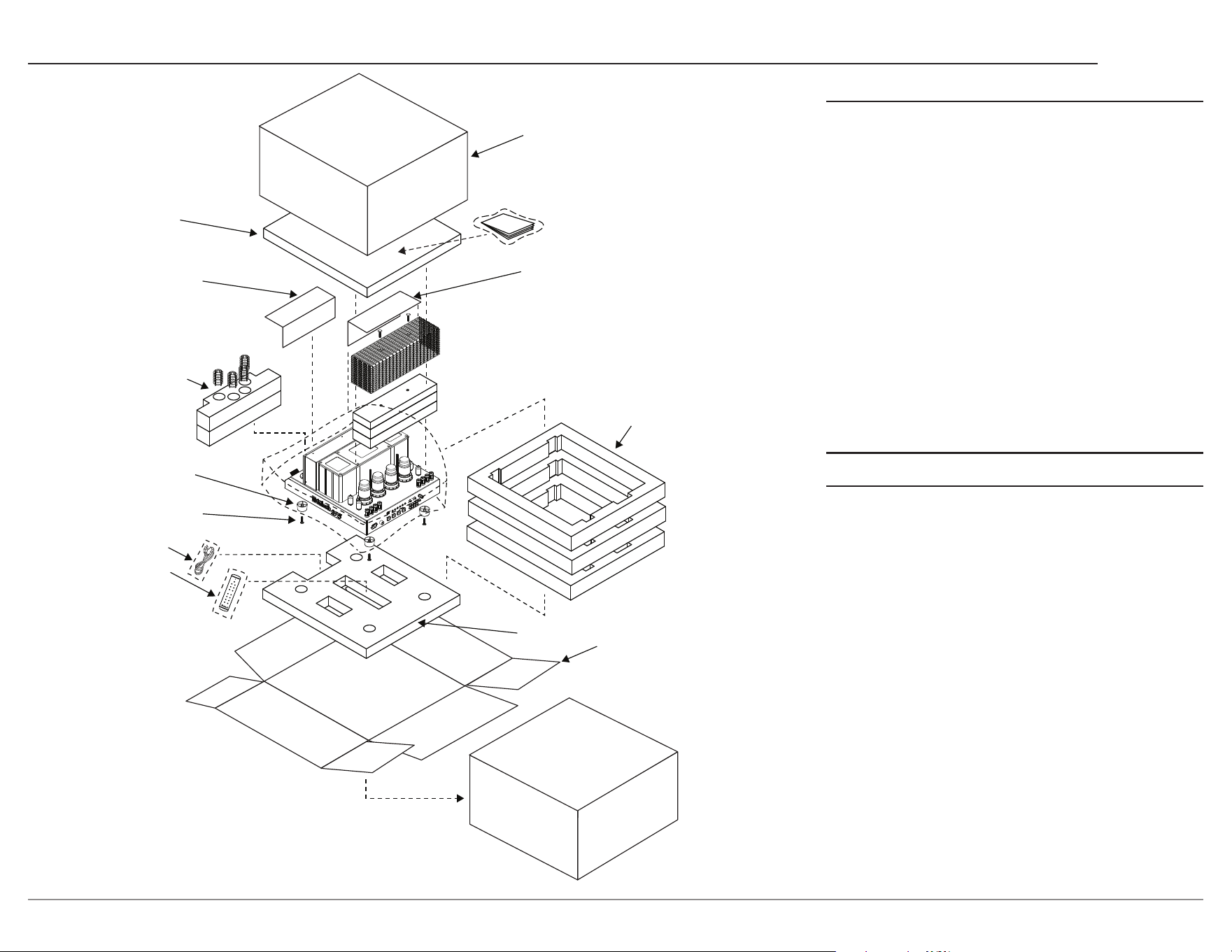
Packing Instructions
MA2375 Packing Material List
Quantity Part Number Description
1 034783 Shipping carton
top
1 753041 Manual package
1 034750 Foam top
3 034751 Foam middle
1 033739 Poly bag
2 241109 Warning sheet
1 034747 Foam tube front
1 034748 Foam tube rear
4 017937 Plastic foot
4 404080 #10 at washer
4 400159 #10-32 x 3/4 inch
screw
1 HR085 Remote control
1 Note 1 AC power cord
1 034785 Foam bottom
1 034784 Shipping carton
bottom
Note1: AC power cords are country specic
In the event it is necessary to repack the equip-
ment for shipment, the equipment must be packed
exactly as shown. It is very important that the
four feet are attached to the bottom of the
equipment. This will ensure the proper equip-
ment location on the foam bottom. Failure to
do this will result in shipping damage.
To protect the tubes during shipment, the foam
inserts removed from the MA2375 need to be re-
inserted. Follow the Foam Removal instructions on
pages 3-4 in the reverse order.
Use the original shipping carton and interior parts
only if they are all in good, serviceable condition.
If a shipping carton or any of the interior part(s) are
needed, please call or write Customer Service Depart-
ment of McIntosh Laboratory, refer to page 2.
Warning Sheet
Foam Insert
for Tubes
and Shields
Plastic foot (4)
10/32 X 3/4” Screw
With Washer (4)
Foam Middle (3)
Foam Bottom
Bottom
Shipping Carton
Foam Top
Warning Sheet
Manual on top
of polybag
Remote
Power Cord
Top
Shipping Carton

Printed in the U.S.A. © 2026 McIntosh Laboratory, Inc. McIntosh Part No. 24131100
The continuous improvement of its products is the policy
of McIntosh Laboratory Incorporated
who reserve the right to improve design without notice.
McIntosh Laboratory, Inc.
2 Chambers Street
Binghamton, NY 13903
www.mcintoshlabs.com
Trademarks of McIntosh Laboratory, Inc.:
The following are Registered Trademarks of McIntosh Laboratory, Inc in multiple jurisdictions around the world: the written McIntosh logo;
the McIntosh Globe logo; the Mc logo; Power Guard; Power Guard Screen Grid Sensor; Power Guard SGS; LD/HP; Dynamic Power Manager;
the 4DPM8 logo; HXD; the HXD logo; Behind The Sound; Legendary Performance.
The following are Trademarks of McIntosh Laboratory, Inc. in multiple jurisdictions around the world: Autoformer; Sentry Monitor; Solid
Cinch; McIntosh Monogrammed Heatsinks; Hybrid Drive; DualView; TripleView; Made of Sound.
The foregoing trademarks, registered and otherwise, are not to be used, reproduced, or registered in any way without the express written
permission of McIntosh Laboratory, Inc.