COMMERCIALDOOROPERATOR
DAVE’sManual
Doc#160948_01
Released:February2,2026

2
DAVECommercialDoorOperator—InstructionalManual
Contents
1.
IMPORTANTSAFETYINSTRUCTIONS
4
2.
PRODUCTDETAILS 8
TechnicalSpecifications
9
MountingHardwareExplained 17
3.
CONFIGURINGOPERATORDRIVESHAFT&HANDING
19
DriveShaft 20
ManualHaulingChain 21
4.
INSTALLATION 22
GetaLoadofDAVE’sFlexibility! 24
I n s t a l l a t i o n S e t u p O p t i o n s 2 5
StepbyStepInstallationSequence 26
DriveUnit
30
WallConsole 35
WarningPlacards
39
5.
CONNECTINGTOPOWER 40
OmniVolt®PowerCartridgeDetails 42
ConnectingOmniVolt®PowerCartridge 43
6.
WIRINGDETAIL 44
MainControlBoardOverview 45
MainControlBoardTerminals 46

3
DAVECommercialDoorOperator—InstructionalManual
7.
SETUP&PROGRAMMINGOPTIONS 48
PairingWallConsole
49
WallConsolePowerModes 51
UsingRemoteControls(Transmitters) 52
SettingLimits 56
OperatorSettings 58
ResettingtoFactoryDefaults
59
ProgrammingOptionsTable 62
8.
SAFETYDEVICESANDOTHERCONTROLINPUTS
71
SafetyDeviceSetup 72
FireSystemInput 77
AccessDevices
79
9.
DAVE’SRELAYEXPANSIONBOARD
82
RelayExpansionBoardOverview 83
RelayBoardWiringExamples 84
10.
MAINTENANCE&SUPPORT 86
DoorServiceAlerts 87
MaintenanceRequirements
89
TroubleshootingGuide
91

4
DAVECommercialDoorOperator—InstructionalManual
1.
IMPORTANTSAFETY
INSTRUCTIONS

5
DAVECommercialDoorOperator—InstructionalManual
WARNING
TOREDUCETHERISKOFSEVEREINJURYORDEATH:
1.
READANDFOLLOWALLINSTRUCTIONS.
2.
Neverletchildrenoperateorplaywithdoorcontrols.Keepremotecontrolsawayfrom children.
3.
Alwayskeepthemovingdoorinsightandawayfrompeopleandobjectsuntilitiscompletelyclosed.NOONESHOULDCROSS
THEPATHOFTHEMOVINGDOOR.
4.
NEVERGOUNDERASTOPPED,PARTIALLYOPENDOOR.
5.
Testdooroperatormonthly.Afteradjustingeithertheforceorthelimitoftravel,retestthedooropener.Failuretoproperlyadjust
theopenerincreasestheriskofsevereinjuryor death.
6.
Forproductshavinganemergencyrelease,usetheemergencyreleaseonlywhenthedoorisclosed,ifpossible.Usecaution
whenusingthisreleasewiththedooropen.Weakorbrokenspringscanacceleratethedoordownward,causingsevereinjuryor
death.
7.
KEEPOVERHEADDOORSANDSHUTTERSPROPERLYBALANCED.Seeuser’smanual.Animproperlybalanceddoor
increasestheriskofsevereinjuryordeath.Aqualifiedservicepersonmustmakerepairstocables,springassemblies,andother
hardware
.
8.
Foroperatorsystemsequippedwithanunattendedorautomaticclosingfeature,thefollowingstatementshallbeposted
adjacenttothewallcontrolinaccordancewithUL325:
“Thisoperatorhasanunattendedoperationfeature.Nooneshouldcrossthepathofthemovingdoor.”
9.
SAVETHESEINSTRUCTIONS.
AVERTISSEMENT
POURRÉDUIRELERISQUEDEBLESSURESGRAVES,
VOIREDEMORT
:
1.
LISEZETSUIVEZTOUTESLESINSTRUCTIONS.
2.
Nelaissezjamaislesenfantsutiliseroujoueraveclescommandesdelaporte.Gardezlestélécommandeshorsdeportéedes
enfants.
3.
Gardeztoujourslaporteenmouvementdansvotrelignedevisionetàl’écartdespersonnesetdesobjetsjusqu’àcequ’ellesoit
complètementfermée. PERSONNE NEDOIT TRAVERSERLA TRAJECTOIREDE LA PORTEEN MOUVEMENT.
4.
NEPASPASSERSOUSUNEPORTEARRÊTÉEOUPARTIELLEMENTOUVERTE.
5.
Testezl’ouvre‐portechaquemois.LaportedegarageDOITinversersacourseaucontactd’unobjetde38mm(1‐1/2po)oud’une
planchede2x4poséeàplatsurlesol.Aprèsavoirréglélaforceoulalimitedecourse,refaitesletestdel’ouvre‐porte.Lefaitde
nepasréglercorrectementl’ouvre‐porteaugmentelerisquedeblessuresgravesoudemort.
6.
Pourlesproduits équipés d’undéverrouillaged’urgence, utilisezce dispositifuniquement lorsquela porteest fermée,si possible.
Faitespreuve deprudence lorsde l’utilisationde cedispositiflorsque laporteestouverte.Des ressortsfaibles oucasséspeuvent
accélérer ladescente delaporte,causantdesblessuresgravesoulamort.
7.
GARDEZLESPORTESBASCULANTESETLESVOLETSROULANTSCORRECTEMENTÉQUILIBRÉS.
Voirlemanueld’utilisation.Une
portemaléquilibréeaugmentelerisquedeblessuresgravesoud e m o r t .U n t e c h n i cien q u a l i f i é doi t e f f e c t u er l e s r é p a ra t i o n s des
câbles,desensemblesderessortsetdesautrescomposants.
8.
Pourlessystèmesd’opérateuréquipés d’unefonction defermetureautomatiqueousanssurveillance,l’avertissement suivant
doitêtreaffichéàcôtéduboutonmuralconformémentàlanormeUL325:
9.
«Cetopérateurestdotéd’unefonctiondefonctionnementsanssurveillance.Personnenedoittraverserlatrajectoiredelaporteen
mouvement.»
10.
Conservezcesinstructions.
6
DAVECommercialDoorOperator—InstructionalManual
PLEASEREADTHESEIMPORTANTSAFETYRULESCAREFULLY
Thesesafetyalertsymbolsindicateapersonalsafetyorpropertydamageinstructionexists.
Thisautomaticdooroperatorisdesignedandtestedtooffersafeserviceprovideditisinstalledandoperatedinstrict
accordancewiththefollowingsafetyrules.Failuretocomplywiththeinstallationinstructionsandthesafetywarningsmay
resultindeath,seriouspersonalinjuryand/orpropertydamage.
WARNING
•
Thedoormayoperateunexpectedly,thereforedonotallow
Anythingtostayinthepathofthedoor.
•
For SAFETY protection, aSafety Beammust befitted withlogic
console.Failuretocomplywillvoidthewarrantyandmayresult
inseriouspersonalinjuryand/orpropertydamage .
•
Thedrivemustnotbeusedwithadoorincorporatingawicket
door,unlessthedrivecannotbeoperatedwiththewicketdoor
open.Thedriveisintendedtobeinstalledatleast2.5mabove
thefloor.
•
DONOTallowchildrentooperatetheopener.Anydevicethat
canoperatetheopener,makesureitisoutofreachofchildren
andthatthedoorwayisinfullviewatalltimes.Seriouspersonal
injuryand/orpropertydamagecanresultfromfailuretofollow
thiswarning.
•
Whenusingautoclosemode,aSafety(PhotoElectric)Beam
mustbefittedcorrectlyandtestedforoperationatregular
intervals.Extremecautionisrecommendedwhenusingauto
closemode.Allsafetyrulesmustbefollowed.
CAUTION:
•
Ifyourfacilityhasnopedestrianentrancedoor,anemergency
accessdeviceshouldbeinstalled.Thisaccessoryallows
manualoperationofthegaragedoorfromoutsideincaseof
powerfailure.
•
Frequentlyexaminetheinstallation,inparticular,springs
andmountingsforsignsofwear,damageorimbalance.DO
NOTuseifrepairoradjustmentisneededsinceafaultinthe
installationoranincorrectlybalanceddoormaycauseinjury.
DONOTattempttorepairthedooryourselfashardwareis
underextremetension.
•
Thedoormustbewellbalancedandingoodworkingorder.
doorsprings,bracketsandtheirhardwareareunderextreme
tensionandcancauseseriouspersonalinjury.Donotattempt
toadjustthem.Afaultydoormustberepairedbyanindustrial
serviceprofessionalpriortoopenerinstallation.
•
Safetybeamsmustbeinstallediftheclosingforceatthe
bottom edge of the door exceeds 400N (40kg)
•
Toavoidseriouspersonalinjuryfromentanglement,removeall
unnecessaryropesorchainsanddisableanyequipmentsuch
aslockswhicharenotneededforpowered operation.
•
Donotwearrings,watchesorlooseclothingwhileinstallingor
servicingagaragedooroperator.
•
Ensureladderisthecorrecttypeforthejobandisonflat
ground.Werecommendtheuserhas3pointsofcontact
whileonladder.
•
Activatetheoperatoronlywhenthegaragedoorisinfullview,
freeofobstructionsandwiththeoperatorproperly adjusted.
•
Theoperatorisnotintendedforusebyyoungchildrenor infirm
personswithoutsupervision.
•
Keepremotecontrolsawayfromchildren.
•
Donotallowchildrentoplaywithdoor controls.
DANGER‐
RISKOFELECTROCUTION:
•
Installationandwiringmustbeincompliancewithyourlocal
buildingandelectricalcodes.
•
Toreducetheriskofelectricshock,thisequipmenthasa
groundingtypeplugthathasathird(grounding)pin.Thisplug
willonlyfitintoagroundingtypeoutlet.Iftheplugdoesnotfit
intooutlet,contactaqualifiedelectriciantoinstalltheproper
outlet.Donotchangethepluginany way.
•
Ifthepowercordisdamaged,itmustbereplacedbythe
manufacturer,itsserviceagentorasimilarlyqualifiedpersonin
ordertoavoidahazard.
•
Connectthepowercordonlytoproperlyearthedmains.Ifan
extensionleadmustbeused,makesureitisa3‐coreleadand
approvedto7ampcapacity.
•
Thisunitisnotuserserviceable.Unplugthepowercordbefore
removingthecover.Ensurethatthepowercordisattached
clearofallmovingparts.Ignoringtheseinstructionscancause
electricshock.
•
Disconnectthepowersupplywhencleaningorother
maintenanceisbeingcarriedout.
7
DAVECommercialDoorOperator—InstructionalManual
VEUILLEZLIREATTENTIVEMENTCESRÈGLESDESÉCURITÉ
IMPORTANTES
Cessymbolesd’alertedesécuritéindiquentqu’ilexisteuneconsignedesécuritépourlespersonnesoulesbiens.
Cetouvre‐porteautomatiqueestconçuettestépouroffrirunservicesûr,àconditionqu’ilsoitinstalléetutiliséenstricte
conformitéaveclesrèglesdesécuritésuivantes.Lenon‐respectdesinstructionsd’installationetdesavertissementsde
sécuritépeutentraînerlamort,desblessuresgraveset/oudesdommagesmatériels.
AVERTISSEMENT
•
Laportepeutsedéplacerdefaçoninattendue;nelaissezrien
danslatrajectoiredela porte.
•
Pourlasécurité,unfaisceaudesécuritédoitêtreinstalléavec
laconsolelogique.Lenon‐respectdecetteexigenceannulera
lagarantieetpeutentraînerdesblessuresgravesoudes
dommagesmatériels.
•
Cedispositifnedoitpasêtreutiliséavecuneporteéquipéed’un
portillon,àmoinsqu’ilnesoitimpossibledefairefonctionnerle
dispositiflorsqueleportillonestouvert.Ledispositifdoitêtre
installéàunehauteurd’aumoins2,5mau‐dessusdusol.
•
NEPERMETTEZPASauxenfantsd’utiliserl’ouvre‐porte.Tout
dispositifpermettantd’actionnerl’ouvre‐portedoitêtretenu
horsdeportéedesenfantsetlaportedoittoujoursresterdans
lechampdevision.Lenon‐respectdecetavertissementpeut
entraînerdesblessuresgravesoudesdommagesmatériels.
•
Lorsdel’utilisationdumodedefermetureautomatique,un
faisceaudesécurité(photoélectrique)doitêtrecorrectement
installéettestérégulièrement.Uneextrêmeprudenceest
recommandéelorsdel’utilisationdumodedefermeture
automatique.Touteslesconsignesdesécuritédoiventêtre
respectées.
ATTENTION:
•
Sivotreétablissementnedisposepasdeported’entrée
piétonne,undispositifd’accèsd’urgencedevraitêtreinstallé.
Cetaccessoirepermetuneutilisationmanuelledelaportede
garagedepuisl’extérieurencasdepannedecourant.
•
Examinezfréquemmentl’installation,enparticulierlesressorts
etlesfixations,afindedécelertoutsigned’usure,dedommage
oudedéséquilibre.N’utilisezpasl’appareilsiuneréparationou
unréglageestnécessaire,carundéfautdansl’installationou
uneportemaléquilibréepeutcauserdesblessures.N’essayez
pasderéparerlaportevous‐même,carlescomposantssont
sousfortetension.
•
Laportedoitêtrebienéquilibréeetenbonétatde
fonctionnement.Lesressorts,supportsetautrescomposants
sontsousfortetensionetpeuventcauserdesblessures
graves.N’essayezpasdelesajustervous‐même.Uneporte
défectueusedoitêtreréparéeparunprofessionneldesportes
industriellesavantl’installationdel’ouvre‐porte.
•
Desfaisceauxdesécuritédoiventêtreinstalléssilaforcede
fermetureaubordinférieurdelaportedépasse400N(40kg).
•
Pouréviterdegravesblessuresparenchevêtrement,retirez
touteslescordesouchaînesinutilesetdésactiveztout
équipementtelquelesverrousquinesontpasnécessaires
pourlefonctionnementmotorisé.
•
Neportezpasdebagues,demontresoudevêtementsamples
lorsdel’installationoudel’entretiend’unouvre‐portede
garage.
•
Assurez‐vousquel’échelleestdutypeappropriépourletravail
etqu’elleestposéesurunsolplat.Ilestrecommandéde
maintenirtroispointsdecontactlorsdel’utilisationdel’échelle.
•
N’activezl’ouvre‐portequelorsquelaportedegarage
estentièrementvisible,dégagéeetquel’ouvre‐porteest
correctementréglé.
•
L’ouvre‐porten’estpasdestinéàêtreutilisépardejeunes
enfantsoudespersonnesinfirmessanssurveillance.
•
Gardezlestélécommandeshorsdeportéedesenfants.
•
Nelaissezpaslesenfantsjoueraveclescommandesdela
porte.
DANGER–RISQUE
D’ÉLECTROCUTION:
•
L’installationetlecâblagedoiventêtreconformesauxcodes
locauxdubâtimentetdel’électricité.
•
Pourréduirelerisqued’électrocution,cetappareilestéquipé
d’uneficheavecbrochedemiseàlaterre.Cettefichenepeut
êtrebranchéequedansunepriseavecmiseàlaterre.Silafiche
n’entrepasdanslaprise,faitesinstallerunepriseconvenable
parunélectricienqualifié.Nemodifiezenaucuncaslafiche.
•
Silecordond’alimentationestendommagé,ildoitêtre
remplacé par le fabricant, son agent deservice ou une
personneégalementqualifiéeafind’évitertout danger.
•
Branchezlecordond’alimentationuniquementàuneprise
correctementmiseàlaterre.Siunerallongedoitêtreutilisée,
assurez‐vousqu’ils’agitd’uncâbleà3conducteurs,approuvé
pourunecapacitéde7ampères.
•
Cetappareiln’estpasréparableparl’utilisateur.Débranchezle
cordond’alimentationavantderetirerlecouvercle.Assurez‐
vousquelecordond’alimentationestdégagédetoutesles
piècesmobiles.Lenon‐respectdecesinstructionspeut
entraîneruneélectrocution.
•
Débranchezl’alimentationélectriquelorsdunettoyageoude
touteopérationdemaintenance.

8
DAVECommercialDoorOperator—InstructionalManual
2.
PRODUCTDETAILS

9
DAVECommercialDoorOperator—InstructionalManual
TechnicalSpecifications
DRIVEUNIT
WALLCONSOLE
Motor type
PMSM
Rated Motor Power
750W (1HP)
Reducer Ratio
50 to 1
Rated Output Torque
32Nm /23.5ft.lb
Max Door Weight
Up to 1000kg / 2200lb balanced *
Max Rated Load (N) 450N
Operating Temperatures
-20°C / -4°F to +65°C /+149°F
Environment
Indoor use only
Output Shaft Diameter
25.4mm /1”
Output Shaft Length
95mm / 3.75”
Max Number of Drive Shaft Turns
58
Standard Operator Sprocket
12 teeth 10B (#50)
Optional Sprockets
10 teeth 12B (#60)
Duty Cycle
Up to 60%**
Weight of Drive Unit, Power Cartridge, Drive Shaft and
Sprocket
12.75kg / 28.1lb
Remote Code Combinations
Over one trillion (AES 128 Code Encryption)
Receiver Memory capacity for Remotes 63
IP Rating
IP42 (when mounted in vertical orientation)
Wireless Wall console range
Control buttons
30m / 98.4ft
Bluetooth
15m / 49ft
Power Options
Battery Powered Alkaline D size 1.5V x 2 (5-year battery life***)
Power Adaptor
+5VDC/ 1A
Powered From Operator 4-core cable
Menu display LCD 4 x lines x 20 characters
LCD backlighting Yes
*Note:Maxdoorweightliftingcapacitymayvarybasedondoorand
operatorsprocketsizes,doorspringtensionandselectedspeeds.
**Basedonamaximum400kgbalanceddoorweight,properly
maintainedandratedbythedoormanufacturerfor60%dutycycle
operation.
***Note:Batterylifecanbelowerorhigherandisdependentonthe
powermodeselectedandenvironmentalfactors
10
DAVECommercialDoorOperator—InstructionalManual
OmniVolt®POWERCA
Mains Power Supply
R
TRIDGE(SoldSeparately)
120-240vac 50/60Hz
230-240vac 50/60Hz
Input Power
1000W 1000W
Input Voltage Fuse
10A 10A
Max Current Consumption
10A
5A
Operating Temperatures
-20°C /-4°F to +65°C /+149°F
-20°C/-4°F to +65°C(+149°F)
DANGER‐
RISKOFELECTROCUTION:
•
Anypermanentwiringconnectionmustbeinstalledbyalicensedelectricianinaccordancewithlocalregulationsandstandards
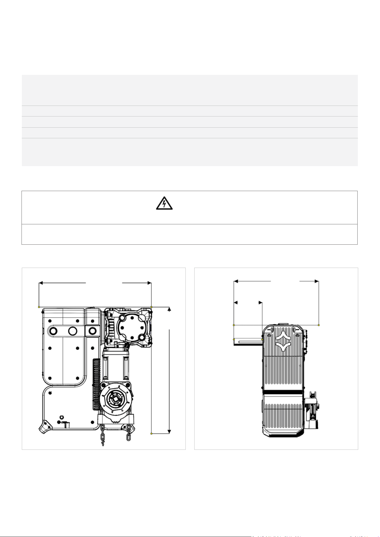
Fig:1SideView
Fig:2FrontView
347mm
13
11/16”
391mm
15/3/8”
290mm
117/16”
100mm
315/16”
11
DAVECommercialDoorOperator—InstructionalManual
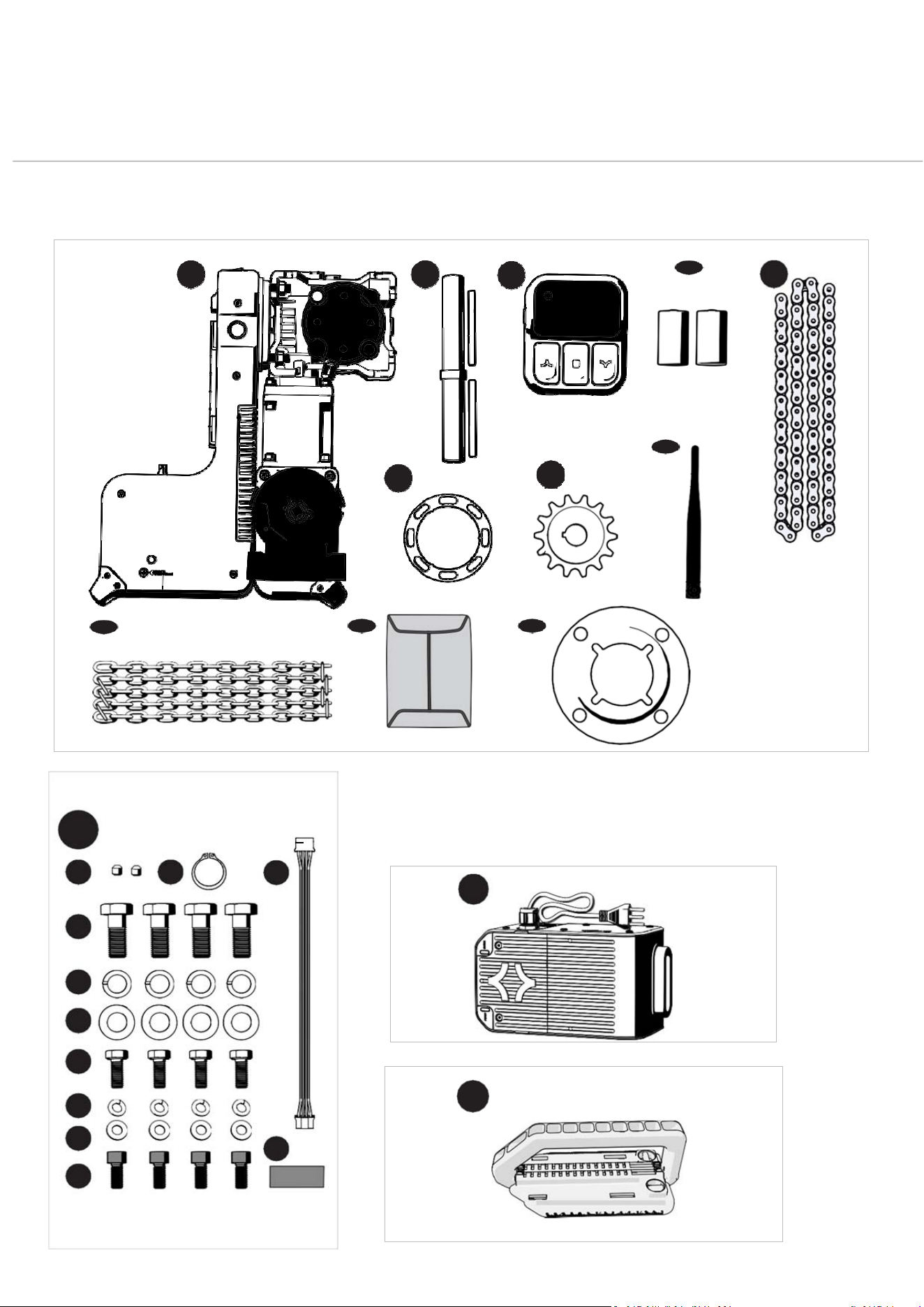
KitContents
P
A
RT
N
O
.
1
01
5
1
0
(
A
U
/
N
Z
)
1
2
4 5 8
7
3
6
9
10
11
SOLDSEPARATELY
10
1
2
10
3
4
5
6
7
8
11
9
AU/NZ
12
13

12
DAVECommercialDoorOperator—InstructionalManual
ITEM DESCRIPTION QTY ITEM DESCRIPTION QTY
1
DRIVE UNIT
1
10/11SELFADHESIVEHOOK&LOOPSTRIP
1
FORWIRELESSBASESTATION
2
OUTPUTDRIVESHAFTASSEMBLY
1
11
FLANGEDMOUNTING ADAPTER(AU/
1
3
MOUNTING BRACKET SPACER
1
NZONLY)
4
WALLCONSOLE
1
5
DCELLALKALINEBATTERIES 2
(FITTEDINWALLCONSOLE)
ITEMSSOLDSEPARATELY
6
SPROCKET 10B
12 OMNIVOLT®POWERCARTRIDGE‐
7
WIRELESSANTENNA
1
PARTNO.101640(LOWVOLTAGE)&
8
DRIVECHAIN12T 10B
1
PARTNO.101642(HIGHVOLTAGE)
9
HAULINGCHAIN(10M)
1
13 DAVE’SHANDLE‐PARTNO.101931
10
ACCESSORIESENVELOPE
1
10/1
5/16”GRUBSCREWSFORSPROCKET 2
10/2CIRCLIPD02500120
1
10/3HEXHEADSCREWZPM12X30 4
10/4SPRINGWASHERI.D.12 4
10/5FLATWASHER12.2X30X2.5 4
106 HEXHEADSCREWM8X20 4
10/7SPRINGWASHERI.D.8 4
10/8FLATWASHER I.D.8 4
10/9SOCHDSCREWM8X18 4
10/10HARNESSFORPE BEAMWIRELESS
1
BASESTATION
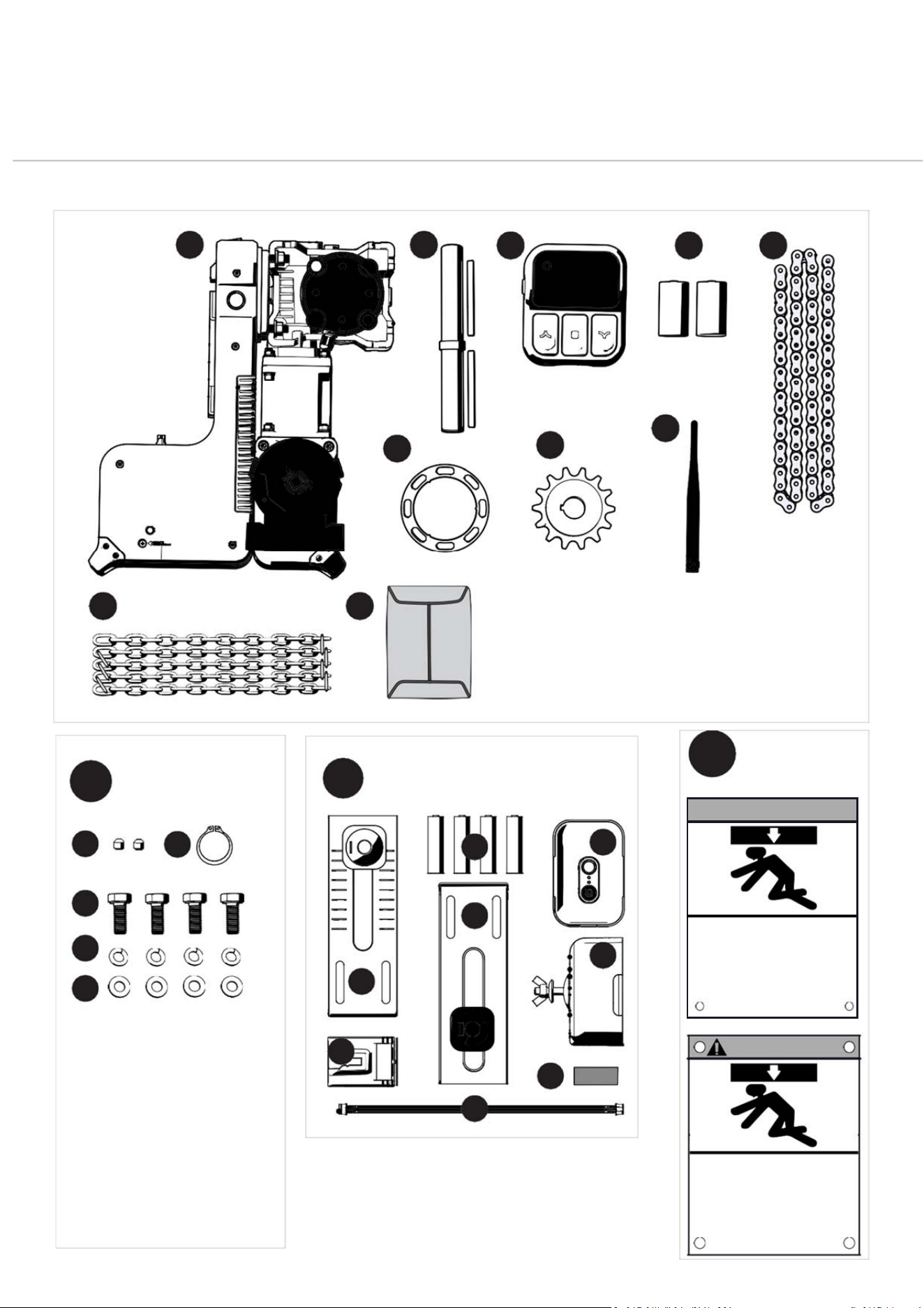
13
DAVECommercialDoorOperator—InstructionalManual
ou la mort
KitContents
PARTNO.101511(NORTHAMERICA)
13
WARNING
Moving Door Can Cause
Serious Injury or Death
Keep Clear! Door May Move at any Time Without
Prior Warning
Do Not Let Children Operate the Door or Play
in the Door Area
Keep Door in Sight at all Times When Door is Moving
AVERTISSEMENT
La porte en mouvement peut
causer des blessures graves
Restez à l’écart de la porte. Celle-ci peut être active
à n’importe quel moment sans avertissement.
Ne laissez pas les enfants manœuver la porte ou
jouer dans la zone de la porte
Gardez la porte en vue en tout temps lorsqu’elle est
en mouvement
12
11
6
3
1
2
4
5
8
7
9
11
6
5
1
2
3
4
5
USA/CANADA
1
1
4
2
2
3
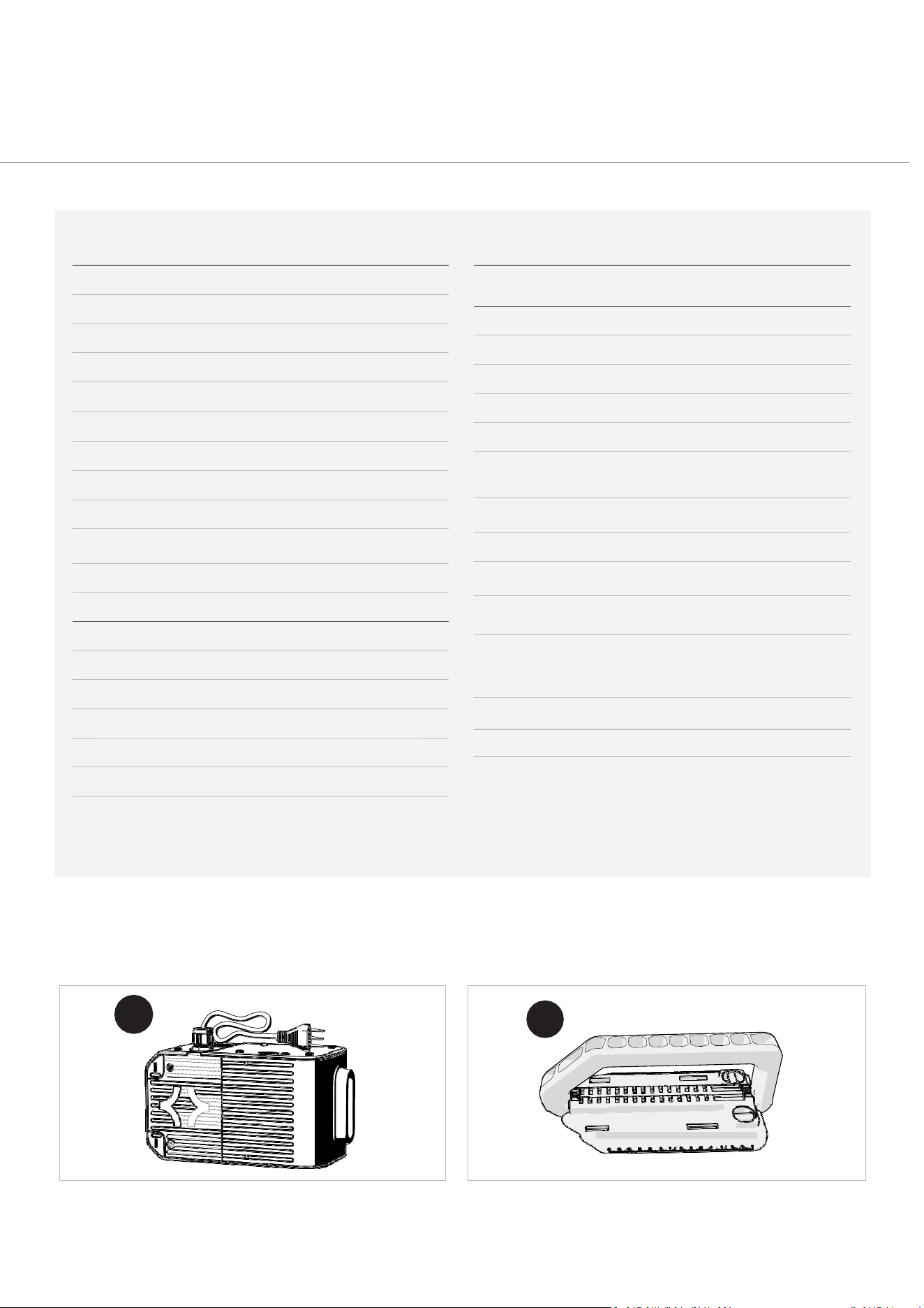
14
DAVECommercialDoorOperator—InstructionalManual
ITEM DESCRIPTION QTY ITEM DESCRIPTION QTY
1
DRIVEUNIT
1
12
WIRELESS‐FIRST SAFETY BEAM
1
KITFORUSONLY
2
OUTPUTDRIVESHAFTASSEMBLY
1
12/1 LBRACKETASSEMBLY 2
3
MOUNTING BRACKETSPACER
1
12/2TRANSMITTER/RECEIVERASSEMBLY 2
4
WALLCONSOLE
1
12/3WIRELESSBASESTATION
1
5
DSIZEALKALINEBATTERIES 2
12/4AASIZEALKALINEBATTERIES 4
6
SPROCKET #50
1
12/5WIRELESSBASESTATIONHARNESS
1
7
WIRELESSANTENNA
1
12/6SELFADHESIVEHOOK&LOOPSTRIP
1
8
DRIVECHAIN10B
1
FORWIRELESSBASESTATION
9
HAULING CHAIN
1
13 SAFETY PLACARDS
1
11
ACCESSORIES ENVELOPE
1
POWERCARTRIDGEOPTIONS
11/1
5/16”SETSCREWSFOR SPROCKET 2
14 OMNIVOLT®POWERCARTRIDGE
11/2
LOCKRINGD02500120
1
PARTNO.101641(LOWVOLTAGE)&
11/3 HEXHEADSCREWM8X20 4
PARTNO.101642(HIGHVOLTAGE)
11/4 LOCKWASHERI.D.8 4
11/5 FLATWASHER I.D.8 4
15 DAVE’SHANDLE(PARTNO. 101931)
SOLDSEPARATELY
14
15
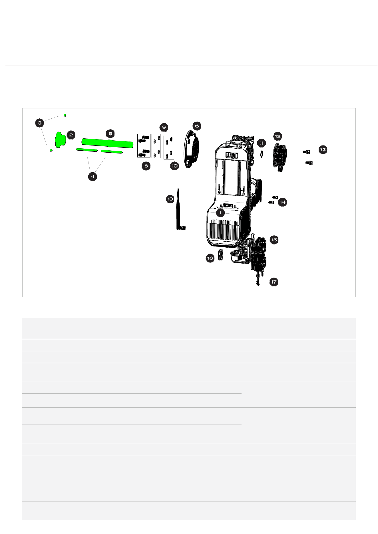
15
DAVECommercialDoorOperator—InstructionalManual
ExplodedParts
Diagrams
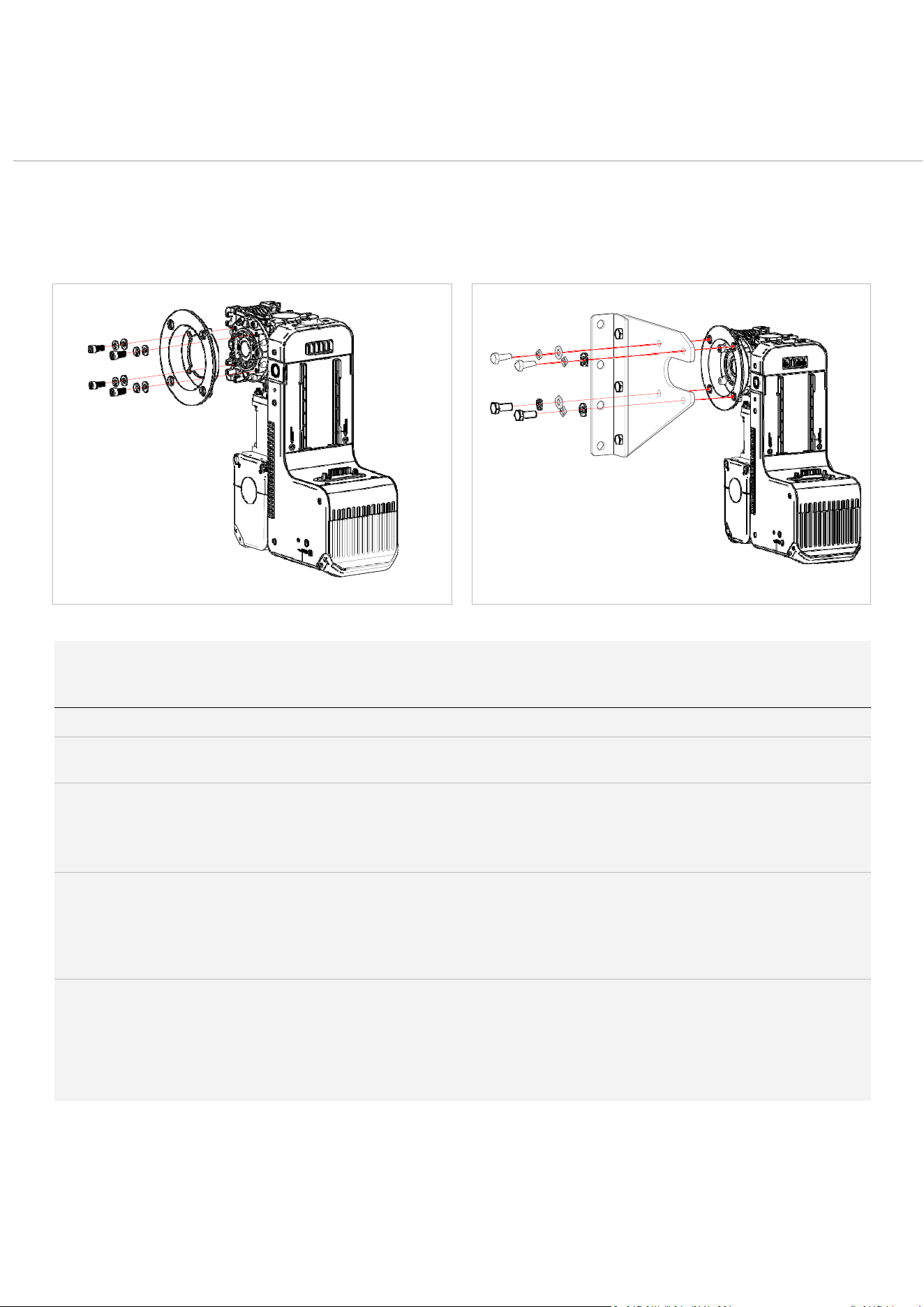
FLANGEDMOUNTINGADAPTORCONFIGURATION(COMMONFOR
AUSTRALIANANDNEWZEALANDROLLERSHUTTERINSTALLATIONS)
ITEM DESCRIPTION
QTY ITEM DESCR
PTION QTY
1 POWERHEAD 1
10 FLATWA
S
HERS 4
2 SPROCKET10B(#50)
1 11
CIRCLIP
(
LOCKRING)
1
3 SPROCKETGRUBSCREWS (
SCREWS)
S
ET 2 12 SURETR
ENCODE
A
CK™POSITIONING
1
R
4 DRIVESHAFTKEYS
2 13 SURETR
A
CK™POSITIONING 2
5 DRIVESHAFT
ENCODE
1
WASHER
RSCREWSWITHCAPTIVE
S
6 AU/NZFLANGED MOUNTIN
ADAPTER(FIG:3ONLY)
G
1
14 HAULIN
G
CHAINASSEMBLYSCREWS 2
7 MOUNTINGBRACKETSPAC
ONLY)
15
HAULING
E
R(FIG:4
1
16
HAULING
CHAINACCESSSLOTCAP
1
CHAINASSEMBLY
1
8 BLACKSOCHEADSCREW
M
8X18 4 17 HAULIN
G
CHAIN
1
Fig:3

16
DAVECommercialDoorOperator—InstructionalManual
9 M8SPRINGWASHERS(LOC
K
4 18 WIRELES
S
ANTENNA
1
WASHERS
)
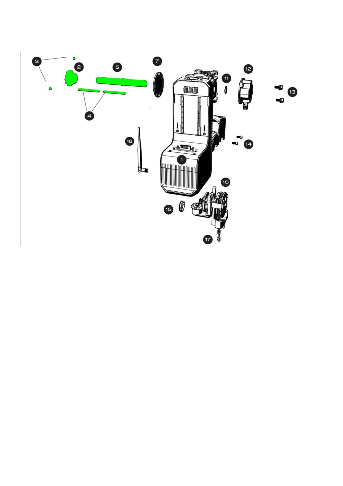
16
DAVECommercialDoorOperator—InstructionalManual
SECTIONALANDHOODMOUNTBRACKETCONFIGURATIONWHEN
USINGHOODMOUNTANDWALLMOUNTBRACKETKITS(COMMONIN
NORTHAMERICA)
Fig:4
17
DAVECommercialDoorOperator—InstructionalManual
MountingHardware
Explained
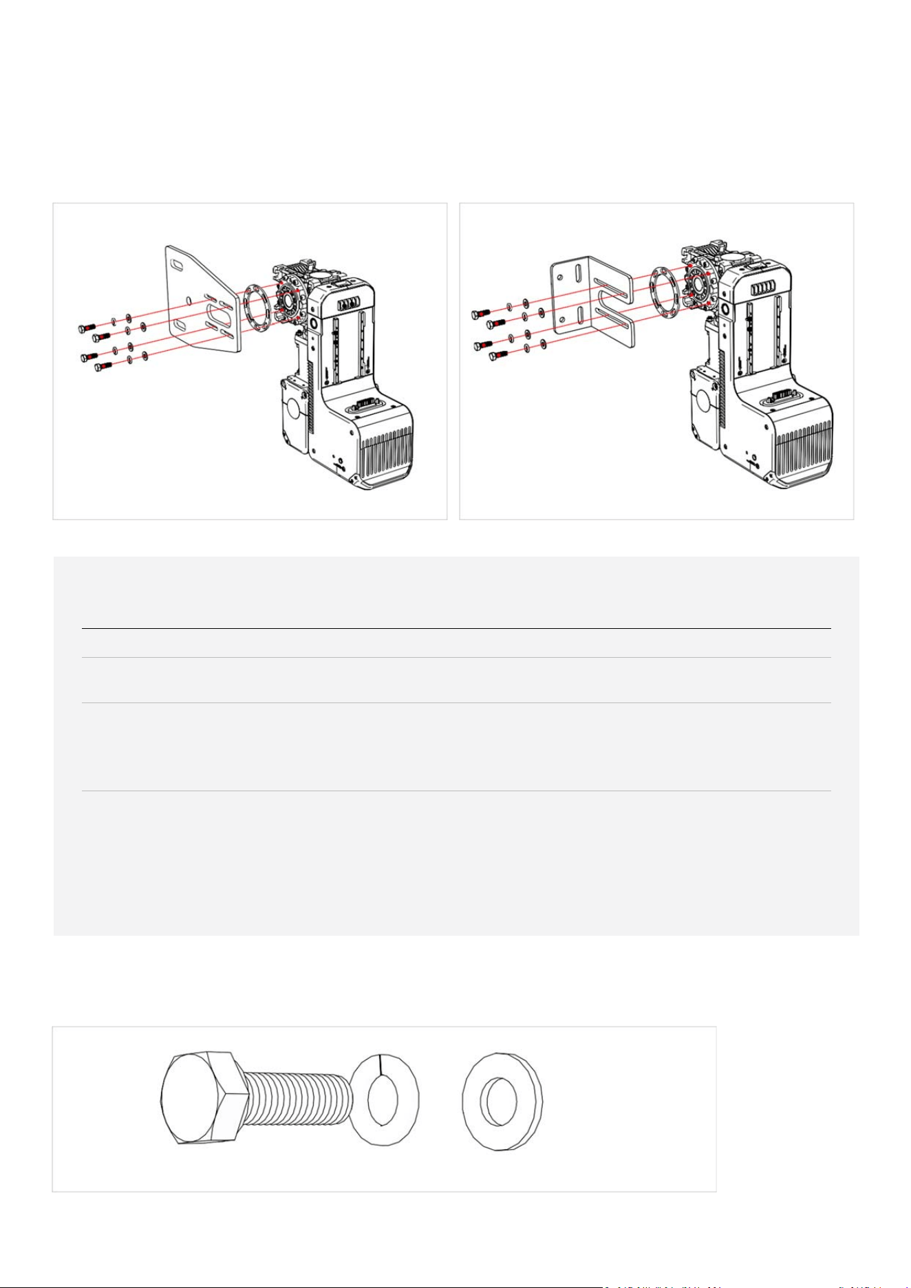
WHENUSINGWITHFLANGEDMOUNTINGADAPTOR(COMMONFOR
AUSTRALIANANDNEWZEALANDROLLERSHUTTERINSTALLATIONS)
Fig:5 Fig:6
F
o
r
P
a
r
t
N
o
.
1
0
1
5
1
0
PART/PARTSET
QTY
WHERETOUSE
5/16”GRUBSCREWS
2
Securesthesupplied10Bdrivesprocket.
CIRCLIPD02500120
1
Requiredforinstallingtheoutputdriveshaftassembly(including
handingchange)
HEXHEADSCREWZPM12X30
SPRINGWASHERI.D.12
FLATWASHER12.2X30X2.5
4
4
4
Fastensthesuppliedflangeadaptortoaneworexistingthird‐party
rollershutterflagbracketFig:6.
BLACKSOCHEADSCREWZPM8
X18
SPRINGWASHERI.D.8
FLATWASHERI.D.8
4
4
4
FORROLLERSHUTTERROLLINGDOORINSTALLS
Fastensthesuppliedflangeadaptortothereducer(gearbox)forroller
shutterinstallsFig:5.
HEXHEADSCREWM8X20
SPRINGWASHERI.D.8
FLATWASHERI.D.8
4
4
4
FORSECTIONALDOORINSTALLSUSINGSECTIONAL
BRACKETKITACCESSORY
Securesthemountingbracketspacertothereducer(gearbox)for
sectionaldoorinstallsFig:8.
18
DAVECommercialDoorOperator—InstructionalManual
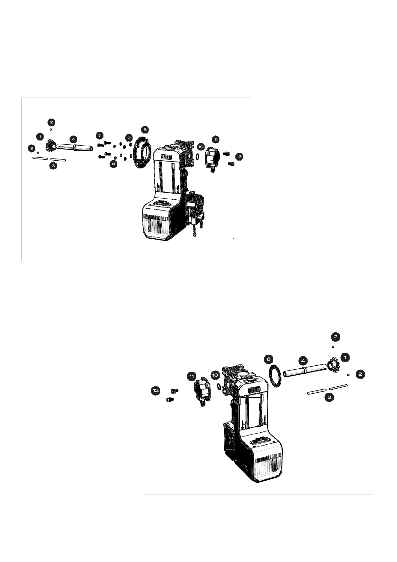
SECTIONALANDHOODMOUNTBRACKETCONFIGURATIONWHEN
USINGHOODMOUNTANDWALLMOUNTBRACKETKITS(COMMONIN
NORTHAMERICA)
Fig:7 Fig:8
F
o
r
P
a
r
t
N
o
.
1
0
1
5
11
CORRECTWASHERORDERONBOLT:LOCK/SPRING
FIRST,FLATSECOND
Fig:9
PART/PARTSET
QTY
WHERETOUSE
5/16”SETSCREWS
2
Securesthesupplied10Bor#50drivesprocket.
LOCKRINGD02500120
1
Requiredforinstallingtheoutputdriveshaftassembly(including
handingchange)
HEXHEADSCREWM8X20
LOCKWASHERI.D.8
FLATWASHERI.D.8
4
4
4
FORSECTIONALANDHOODMOUNTDOORINSTALLSUSING
WALLANDHOODMOUNTBRACKETKITACCESSORIES
Securesthemountingbracketspacertothereducer(gearbox)for
sectionalandhoodmountdoorinstallsFig:7‐Fig:8.

19
DAVECommercialDoorOperator—InstructionalManual
3.
CONFIGURINGOPERATOR
DRIVESHAFT&HANDING
20
DAVECommercialDoorOperator—InstructionalManual
DriveShaft
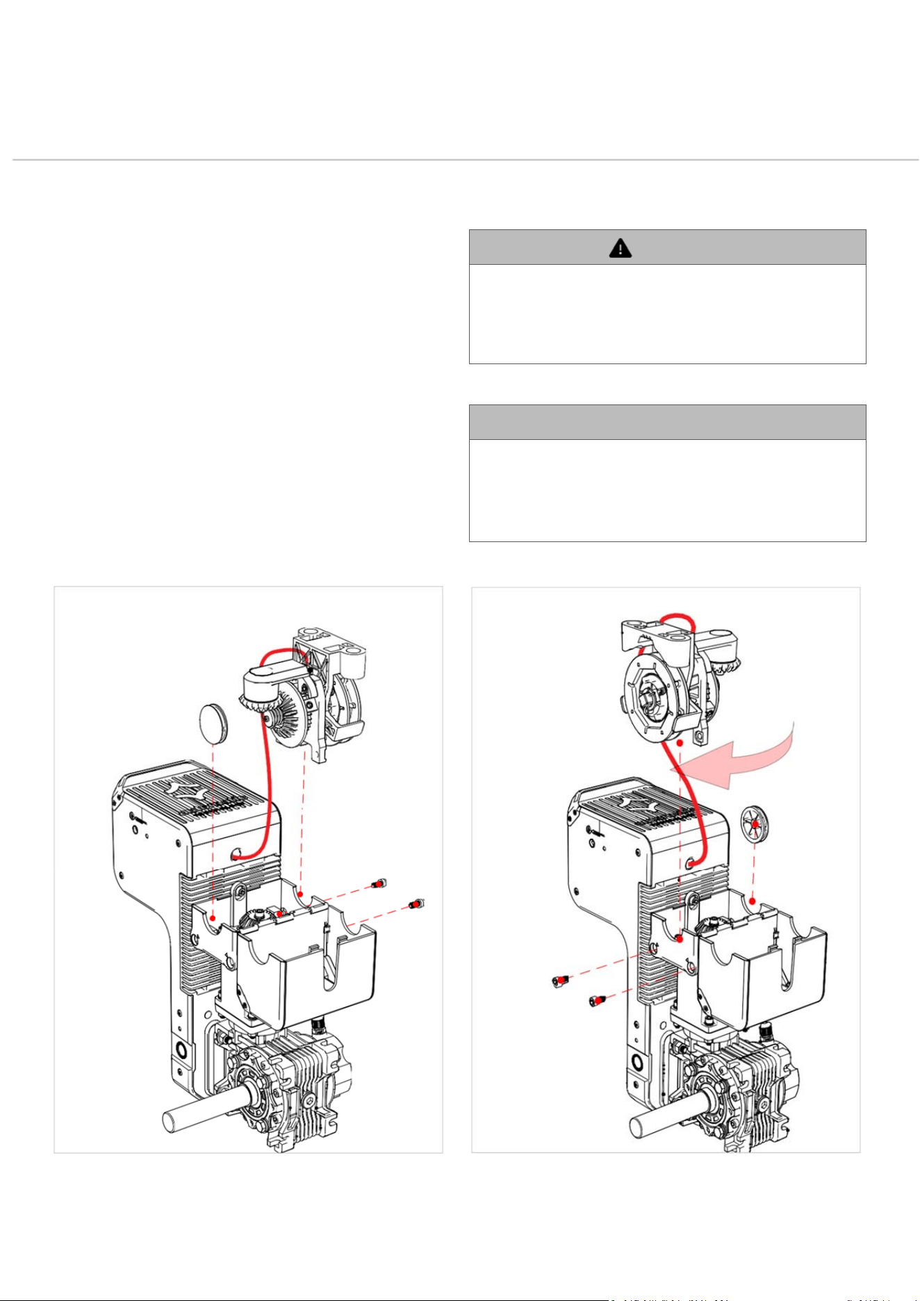
RightHandDriveAssemblyforRollerShutterusingFlangedMountingAdaptor:
Exploded
view of drive shaft encoder and positioning encoder arranged for right-hand positioning of
the operator (looking from inside the building outwards).
DRIVEASSEMBLY
REVERSIBLEPARTS
KEY
1.
UnscrewSureTrack™positioning
encoder
2.
Assembledriveshafttorequired
handing(Left/Right),makingsureto
includetheshaftkeyatthereducer
end.
3.
Attachcirclip(lock‐ring)tosecure
driveshaft.
4.
AlignSureTrack™positioning
encodershaftkeytointeriorshaft
key‐wayindriveshaft adaptor.
5.
AssembleSureTrack™positioning
encodertooppositesideofdrive
shaft.
6.
Assemblesprocketandkeyonto
driveshaft.Hand‐tightensprocket
grub(set)screws,allowingaslight
give.Thiswillneedtoberemoved
andreattachedwhenmounting.
7.
Donotattachoperatortomounting
bracketorflangedadaptoruntilthe
brackethasbeenfixedtosubstrate.
1.
Sprocket
2.
SprocketGrubScrewsx2
3.
DriveShaftKeys
4.
DriveShaft
5.
MountingAdaptor(AU/NZOnly)
6.
MountingBracketSpacer(Donot
usewithAU/NZMounting Adaptor)
7.
M8x20BlackSocketHeadScrews
8.
M8SpringWashers(LockWashers)
x4
9.
M8FlatWashersx4
10.
Circlip(LockRing)
11.
SureTrack™positioningencoder
12.SureTrack™positioningencoder
Screwsandcaptivewashers(M8x18)
x2
Fig:11
LeftHandDriveAssemblyforSectionalandHoodMounts
Exploded view of drive and timing
components arranged for left-hand positioning of the operator (looking from inside the
building outwards).
Fig:10
21
DAVECommercialDoorOperator—InstructionalManual
ManualHaulingChain
1.
Unclipandhingeopenthehaulingchainassemblycover.
2.
Slideoutthecapfromtheunusedhaulinggearaccessslot.
3.
Unfastenthehaulingchaingearbyremovingthehexbolts
andliftingouttheassembly.
4.
Notethemicroswitchcablethatconnectsthehauling
chainassemblytothedriveunit.Takecarenottotangle
orbreakthiswhilechangingthehaulingchainassembly
position.
5.
Switchthecapandhaulingchainassemblyintothe
oppositeslotsandrefastenthehexbolts.
6.
Closetheassemblychaincover,makingsureithas
clippedshutsecurely.
Changing Side of Hauling Chain Assembly
Warning
•
Toavoidaccidentalentanglementofthehaulingchainwiththe
drivemechanism,itisstronglyrecommendedtopositionthe
manualhaulingchainontheoppositesideoftheoperatortothe
drivesprocket.Failuretodosomayresultinseriousinjuryand
permanentdamagetotheoperator.
AVERTISSEMENT
•
Pourévitertoutrisqued’enchevêtrementaccidenteldela
chaînedemanœuvreaveclemécanismed’entraînement,ilest
fortementrecommandédepositionnerlachaînedemanœuvre
manuelleducôtéopposéàceluidupignond’entraînement.Le
non‐respectdecetteconsignepeutentraînerdesblessures
gravesetdesdommagespermanentsàl’opérateur.

22
DAVECommercialDoorOperator—InstructionalManual
4.
INSTALLATION

23
DAVECommercialDoorOperator—InstructionalManual
ImportantInstallationInstructions
WARNING
TOREDUCETHERISKOFSEVEREINJURYORDEATH:
a.
READANDFOLLOWALLINSTALLATIONINSTRUCTIONS.
b.
Installonlyonaproperlybalancedgaragedoor.Adoorthatisoperatingimproperlycouldcausesevereinjury.Havequalified
servicepersonnelmakerepairstocables,springassemblies,andotherhardwarebeforeinstallingtheoperator.
c.
Removeallpullropesandremove,ormakeinoperative,alldoorlocks(ifany)thatwillinterferewithoperationofthedoor
connectedtothedoorbeforeinstallingtheoperator.
d.
Acommercial/industrialdooroperatorthathasexposedmovingpartscapableofcausinginjurytopersonsordamageto
propertyshallbelocatedorguardedsoastoavoidhazards,inaccordancewithUL325requirements.
e.
Iftheoperatormustbeinstalledlessthan2.44m(8ft)abovethefloor,thenexposedmovingpartsmustbeprotectedbyguarding
toavoidhazards.
f.
Locatethecontrol button:
i.
Withinsightofthedoor,
ii.
Ataminimumheightof1.53m(5ft)abovethefloorsosmallchildrenarenotabletooperateit,and
iii.
Awayfromallmovingpartsofthedoor.
g.
Allwarningsignsandplacardsmustbeinstalledwherevisibleintheareaofthedoor
h.
InstalltheEntrapmentWarningPlacardnexttothecontrolbuttoninaprominentlocation.Theplacardisincludedin
theliteraturepack.Placardmustbeinstalledatleast1.53m(5ft)abovefloorlevel(UL325/CSArequirement)
i.
Afterinstallingtheoperator,thedoormustreversewhenitcontactsa38‐mm(1‐1/2in.)highobjectora2x4boardlaidflatonthe
floor.
j.
SAVETHESEINSTRUCTIONS.
Instructionsd’installationimportantes
AVERTISSEMENT
POURRÉDUIRELESRISQUESDEBLESSURESGRAVES
OUDEMORT
:
a.
LISEZETSUIVEZTOUTESLESINSTRUCTIONSD’INSTALLATION.
b.
N’installezl’ouvre‐portequesuruneportedegaragecorrectementéquilibrée.Uneportequifonctionnemalpeutcauserdes
blessuresgraves.Faitesréparerlescâbles,lesressortsettoutautrecomposantparuntechnicienqualifiéavantd’installer
l’opérateur.
c.
Enleveztouteslescordesdetirageetretirezourendezinopérantstouslesverrousdeporte(lecaséchéant)quipourraientgêner
lefonctionnementdelaporteavantd’installer l’opérateur.
d.
Unopérateurdeportecommerciale/industriellecomportantdespiècesmobilesexposéessusceptiblesdecauserdesblessures
oudesdommagesdoitêtreinstalléouprotégédefaçonàévitertoutdanger,conformémentauxexigencesUL325.
e.
Sil’opérateurdoitêtreinstalléàmoinsde2,44m(8pi)dusol,lespiècesmobilesexposéesdoiventêtreprotégéesparun
dispositifdeprotectionpourévitertoutdanger.
f.
Placezleboutondecommande:
i.
àunendroitd’oùlaporteestvisible,
ii.
àunehauteurminimalede1,53m(5pi)dusolafinquelesjeunesenfantsnepuissentpasl’atteindre,
iii.
àl’écartdetouteslespiècesmobilesdelaporte.
g.
Touslespanneauxetplaquettesd’avertissementdoiventêtreinstallésàunendroitbienvisibledanslazonedelaporte.
h.
Installezlaplaquetted’avertissementcontrelehappementàcôtéduboutondecommande,àunendroitbienenvue.Laplaquetteest
inclusedanslekitdedocumentation.Elledoitêtreinstalléeàaumoins1,53m(5pi)dusol(exigenceUL325/CSA).
i.
Aprèsl’installationdel’opérateur,laportedoitinversersonmouvementlorsqu’elleentreencontactavecunobjetde38mm(1‐1/2
po)dehauteurouuneplanchede2x4poséeàplatsurlesol.
j.
CONSERVEZCES INSTRUCTIONS.

24
DAVECommercialDoorOperator—InstructionalManual
GetaLoadofDAVE’s
Flexibility!
DAVEisincrediblyversatileandcanhandlejustaboutanycommercialorindustrialdoor
typeorinstallationstyle.
Justafewminutesofpre‐planningwillmeanyoucantakefulladvantageofDAVE’stime‐
savinginstallationbenefits.
WirelessorWired?youchoose!
Unlessyoureallylovewires,wesuggestyouoptforawireless
setup.
CompatibleAutomaticTechnologysafetybeamsandDAVE’s
WallConsolebothdeliverreliable,longlastingperformance
viastandardalkalinebatteries.Alternatively,theycandraw
powerfromDAVEitself,orifpreferred,theconsolecaneven
bepoweredbyanindependent5VDCpowersupply.
Orientation
DAVEcanbeinstalledinanyorientation,vertically,
horizontally,orevenupside‐down.
Power
Totakeadvantageofpre‐wiredpowercartridgecable,
requiresastandardelectricalwalloutletlocatedwithin
1
meter(3feet)ofthedriveunit. Alternatively,thepower
cartridgecanbehardwiredintothemainsbyaqualified
electrician.
MandatorySafetydevice
Requirement
Asafetydevicemustbeconnectedtotheoperatorand
positionedasclosetothedoor’stravelpathaspossible.
Note:thisoperatormusthaveatleastonesafetydevice
connectedinordertofunctionwithoutconstantcontact
(dead‐man)mode.
25
DAVECommercialDoorOperator—InstructionalManual
InstallationSetupOptions
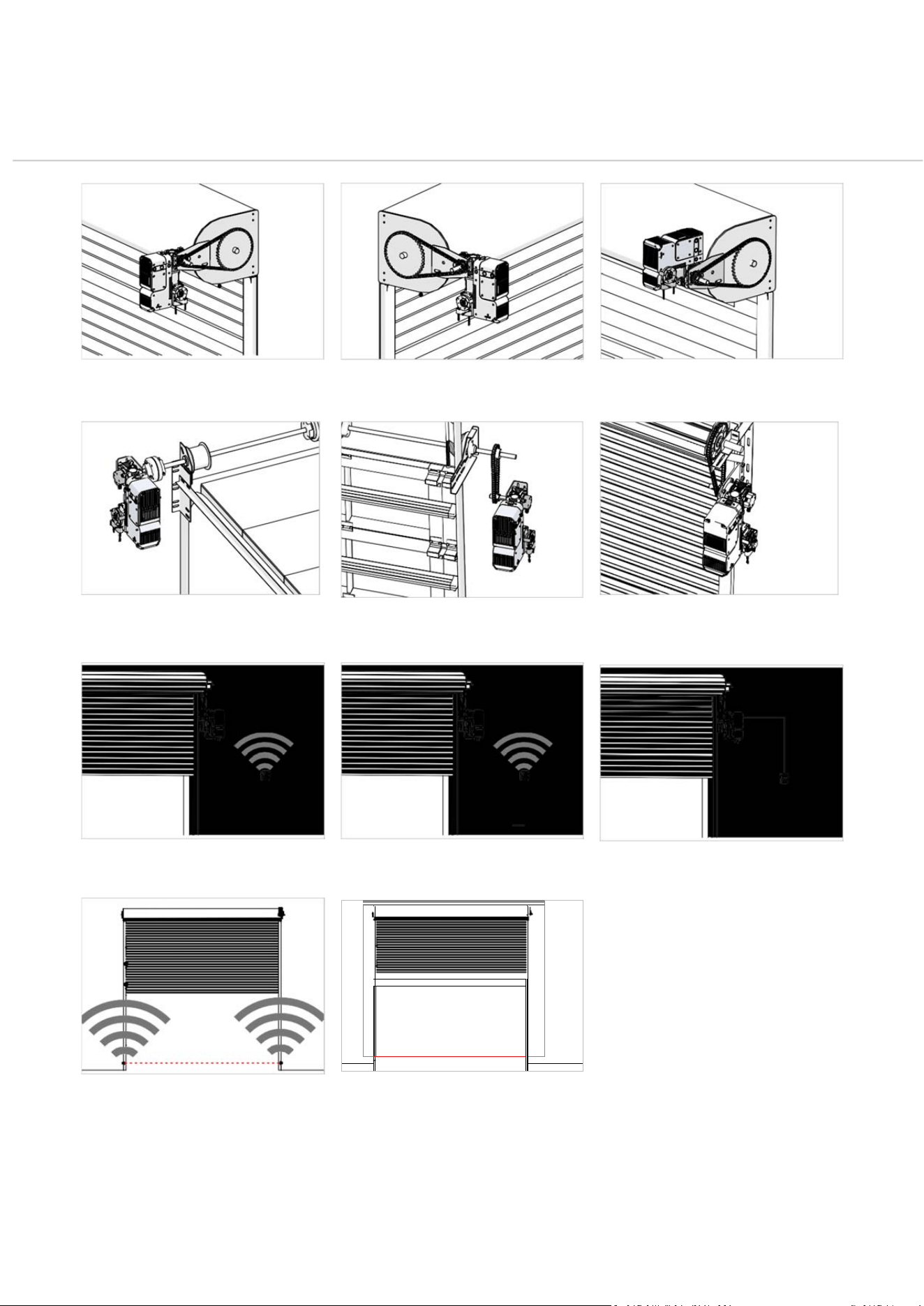
Right Hand Vertical Hood Mount Rolling Steel Left Hand Vertical Hood Mount Rolling Steel Right Hand Horizontal Hood Mount Rolling Steel
Le f t Hand D i re ct Coup l ed Sec t i onal Ri g ht Ha n d S proc k e t to Sp r o cket / Jack Shaft
Vertical Lift
R i g h t Ha nd F ix e d A xl e Sp r oc k et t o S p ro c ke t Ro ll e r
Shutter
Battery Powered Wireless Console 5VDC Mains Powered Wireless Console
Operator Powered Wired Console
Battery Powered Wireless Safety Beam Wired Safety Beam

26
DAVECommercialDoorOperator—InstructionalManual
StepbyStepInstallation
Sequence
DANGER‐INCORRECTINSTALLATIONCANLEADTOSEVEREINJURY
ORDEATH.FOLLOWALLINSTALLATIONINSTRUCTIONS.
D A N G E R – U N E I N S T A L L A T I O N I N C O R R E C T E P E U T E N T R A Î N E R
DESBLESSURESGRAVESOULAMORT.SUIVEZTOUTESLES
INSTRUCTIONSD’INSTALLATION.
Pre‐InstallationPlanning
1.
Identifydoortypeandmounting hardware
❒
Determineifthedoorissectional,rollingsteel,or shutter.
❒
Chooseappropriatemountingbracketsandadaptors.
2.
Checkdoorconditionandbalance
❒
Ensurethedoorcantravelfeelyintheguidesforthefull
traveldistanceinbothdirections,andandisingoodworking
order.
❒
Clampitsecurelytopreventmovementduringinstallation.
3.
Confirminstallationsideandorientation
❒
Chooseleftorrightside.
❒
DAVEcanbemountedvertically,or horizontally.
4.
Verifymountingsurface
❒
Ensurethewallorstructureissolid(concrete,brick,orsteel)
andcansupportthefullforceappliedtothe door..
5.
Checkclearances
❒
Maintainatleast10mm(½”)betweenthedriveunitandany
structure.
❒
Overheadclearanceshouldbeatleast150mm(6”)
27
DAVECommercialDoorOperator—InstructionalManual
MechanicalInstallation
WARNING
Whenmountingtheoperatorbracketmakesuretousefastenersthataresuitablefor
thesubstrate(e.g.concrete,brick,steel,timber).Bracketmountingfastenersarenot
supplied.
AVERTISSEMENT
Lorsdelafixationdusupportdel’opérateur,utilisezdesfixationsadaptéesaumatériau
desupport(parexemple:béton,brique,acier,bois).Lesfixationspourlemontagedu
supportnesontpasfournies.
6.
Assembledriveshafttodesired
handedness
•
UnscrewtheSureTrack™positioningencoder,fitshaftforleft
orright‐handdriveasrequired,attachcirclip,andre‐attachthe
positioningencoder‐seeOutputShaftonpage21.
7.
Moveuptooperatormountinglevel
•
Ensureyouhavesafeaccesstothemountinglevelandenough
spaceto work.
•
Takeallrequiredtools,hardware,andcomponentswithyou
beforestartingbracketinstallation.
8.
Positionandfixthemountingbracket
•
Selectabracketsuitableforthedoortypeandinstallationstyle‐
seeAvailableBracketsonpage31.
•
Securethebrackettoasolidsurface,ensuringcorrectalignment
forthedriveunit.
•
Whenmountingtheopeneranditsaccessories,usethecorrect
bracketmountingfastenersforthespecificwallorstructure
material.(Bracketmountingfastenersarenot supplied).
9.
AttachDAVE’sinstallationhandle
•
WerecommendusingDAVE’sinstallationhandletomake
mountingeasierandsafer‐seeDAVE’sHandleonpage30.
•
Itprovidesbettergripandcontrolduringinstallationandcanbe
removedoncetheoperatorissecured.
10.
Mounttheoperatortothebracket
•
Securetheoperatorfirmlytothebracketusingthesupplied
hardware.
•
Ensuretheoperatoriscorrectlyalignedandstablebefore
proceeding.
11.
Fitthedrive connection
Dependingontheinstallationtype,chooseoneofthefollowing:
1.
Sprocket‐to‐sprocketdrive:
❒
Fitthedrivesprockettotheshaftandalignitwiththedoor
gear.
❒
Tightenthegrubscrewssecurely.
❒
Shortenthedrivechainasrequiredandfititsecurelyaround
thedrivesprocketanddoorsprocket.
2.
Directcoupling:
❒
Fixthecouplingdirectlytotheshaftanddoor gear.
12.
Fitthehaulingchain
•
Feedthehaulingchainthroughtheguideandoverthechain
wheel.
•
Shortenasneededandensureitisnottwisted.
•
Fixtheendstogethertoformasecureloopusingthechainjoiner
link.
13.
RemoveDAVE’sinstallationhandle
•
Oncetheoperatorismountedandsecured,removethehandle‐
seeConnectingOmniVolt®PowerCartridgeonpage43
IMPORTANTTECHNOTE
Forsprocketdriveinstallations,ensurethesprocketGRUBSCREWS(SETSCREWS)are
adequatelytightenedandcheckedregularly.
NOTETECHNIQUEIMPORTANTE
Pourlesinstallationsavecentraînementparpignon,assurez‐vousquelesVISSANS
TÊTEdupignonsontcorrectementserréesetvérifiéesrégulièrement.
28
DAVECommercialDoorOperator—InstructionalManual
ConnectWallConsole
COMPLETETHISSTEPATOPERATORMOUNTINGLEVEL
14.
Setupthewallconsoleforeitherwireless
orwiredconnection
Thewallconsolesupportsbothwirelessandwiredinstallation.
Installersmustselectoneconnectionmethodandfollowthe
appropriatesteps:
1.
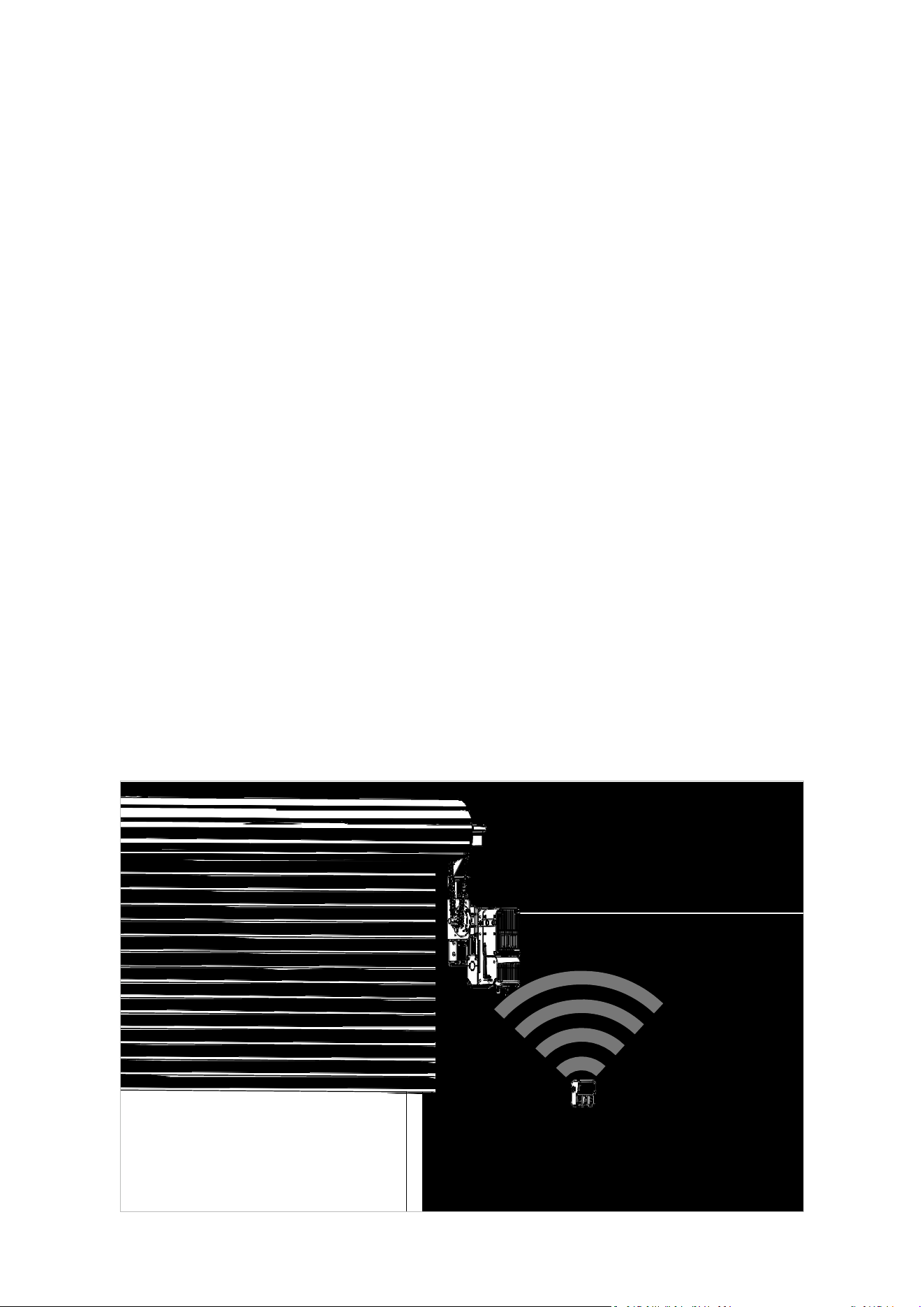
Wirelessconnection(recommended):
❒
Attachthewirelessantennatothesideantennaportonthe
driveunit.
❒
Itisstronglyrecommendedtousethesuppliedconsole
batteriesduringinstallation.
2.
Wiredconnection:
❒
ConnecttheconsoleusingtheWallConsoleWiringKit(Part
No.102189,soldseparately)‐seeConnectingConsoleto
OperatorByCableonpage 37.
WARNING
Ifusingawiredconnectionbetweenconsoleandoperator,donotturnthepoweronto
theoperatorbeforeconnectingtheconsole.
AVERTISSEMENT
Sivousutilisezuneconnexionfilaireentrelaconsoleetl’opérateur,nemettezpas
l’opérateursoustensionavantd’avoirconnectélaconsole.
WARNING
Whenusingawiredconnectionforthewallconsole,ensurethatthewallconsolewiring
cableisaffixedproperlyandawayfromthemovingpartsofthedoorandoperator.
AVERTISSEMENT
Lorsquevousutilisezuneconnexionfilairepourlaconsolemurale,assurez‐vousquele
câbledelaconsolemuraleestcorrectementfixéetéloignédespiècesmobilesdela
porteetdel’opérateur.
29
DAVECommercialDoorOperator—InstructionalManual
InstallAccessories
COMPLETETHISSTEPATOPERATORMOUNTINGLEVEL
15.
Installanyrequiredoroptional
accessories
Accessoriesinclude:
❒
PEBeam(photoelectricsafetybeam)‐seeSafetyDevice
Setuponpage72
❒
LightCurtain‐seeLIGHTCURTAINSonpage76
❒
FireAlarm/SmokeBaffle‐seeFireSystemInputonpage
77
PowerConnection
❒
OptionalRelayModule
❒
Othercompatiblesafetyorcontroldevices‐seeWiring
OtherDevicesonpage 85
COMPLETETHISSTEPATOPERATORMOUNTINGLEVEL
16.
Installtheappropriatepower cartridge
❒
SeeOmniVolt®PowerCartridgeDetailsonpage42
❒
Usethecorrectcartridgefortheinstallation type.
❒
Ensurethepowersourceiswithinreachorarrangefor
hardwiringbyaqualifiedelectrician.
Ground‐LevelSetup
18.
Movetogroundlevel
❒
Relocatetogroundleveltocompletewallconsole
installationandsystemsetup.
19.
Mountthewallconsoletothewall
❒
Chooseasuitablelocationthatiseasilyaccessibleand
visibletousers.
❒
Mounttheconsolesecurelyusingappropriatefasteners
forthewallmaterial‐seeMountConsoletoWallwith
AppropriateFastenersandInsertBatteriesonpage35
❒
Ensuretheconsoleislevelandpositionedatacomfortable
operatingheight.
17.
Connectpowertothe operator
❒
Pluginthepowercartridgeorcompletehardwiring.
❒
Turnonpoweronceallconnectionsaresecure.
20.
ProgramOperatorviaWallConsole
❒
Usethewallconsoletocompletesetup‐seeSettingLimits
onpage56
❒
Selectdoortype
❒
Setcloseandopenlimits
❒
Adjustdoorspeed
❒
Addremotecontrols
❒
Setpedestrianposition
❒
Setsmokebaffleposition
❒
Configuresafetybeambehaviour
❒
Personaliseadditionalfunctions
Typical setup with wireless console connection
30
DAVECommercialDoorOperator—InstructionalManual
DriveUnit
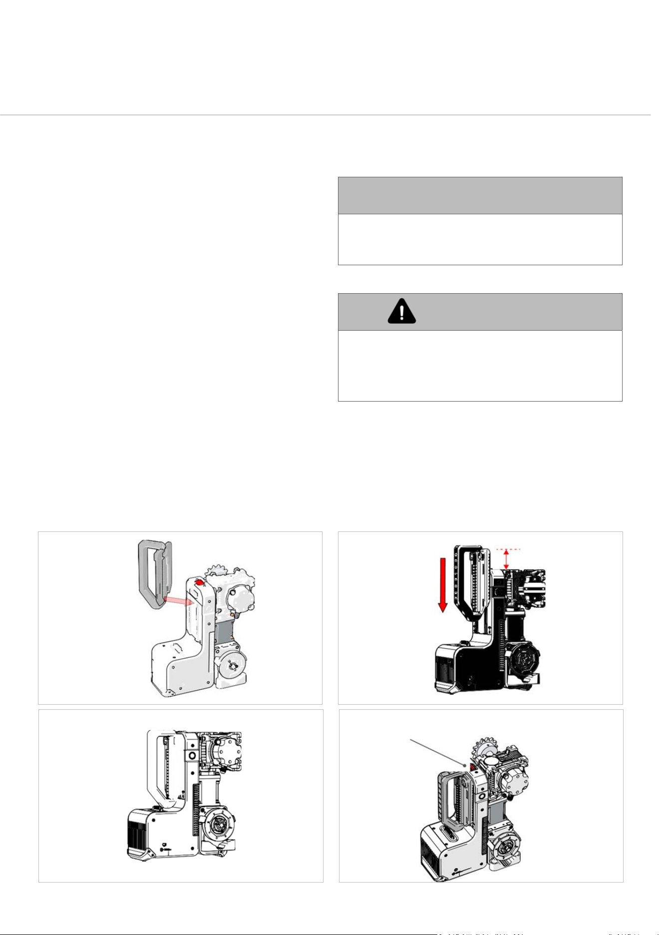
DAVE’sHandle
DAVE’shandleismadeforinstallers.Useit
oneveryjob,againandagain.It’sdesigned
soyoucanliftandcarryDAVEone‐handed.
Itmakesinstallingquickandclean,no
stuffingabout.
1.
FittingtheHandle
Alignthebottomlockingtabsonthehandle’sbasewiththeupper
lockingtabsontheDAVE’Smountingtracks(Fig:12)andslidethe
handledownasfarasitwillgo.
2.
BeforeliftingDave,makesurethehandle
issecurely attached.
Listenforastrongclickasthelockinglatchsnapsintoplaceandpull
backonthehandlefirmlytoconfirmitislockedandready(Fig:15).
3.
RemovingtheHandle
Onceyou’vemountedDAVEsecurelyintoplace,youcangoahead
andremovethehandle.
Pushthelockinglatchawayfromthehandletorelease(Fig6).Then
slidethehandleupwardsuntilthelockingtabsarefreefromthe
mountingrailandliftitoff.
LOCKING
LATCH
MUST
CLICK!
Fig:15
Fig:14
Fig:12
≈25‐30mm/1‐1¼”
Fig:13
WARNING
Ifthelatchdoesn’tclick,thehandlemay
detachduringlifting.
AVERTISSEMENT
Sileloquetnes’enclenchepas,la
poignéepeutsedétacherpendantla
levée.
31
DAVECommercialDoorOperator—InstructionalManual
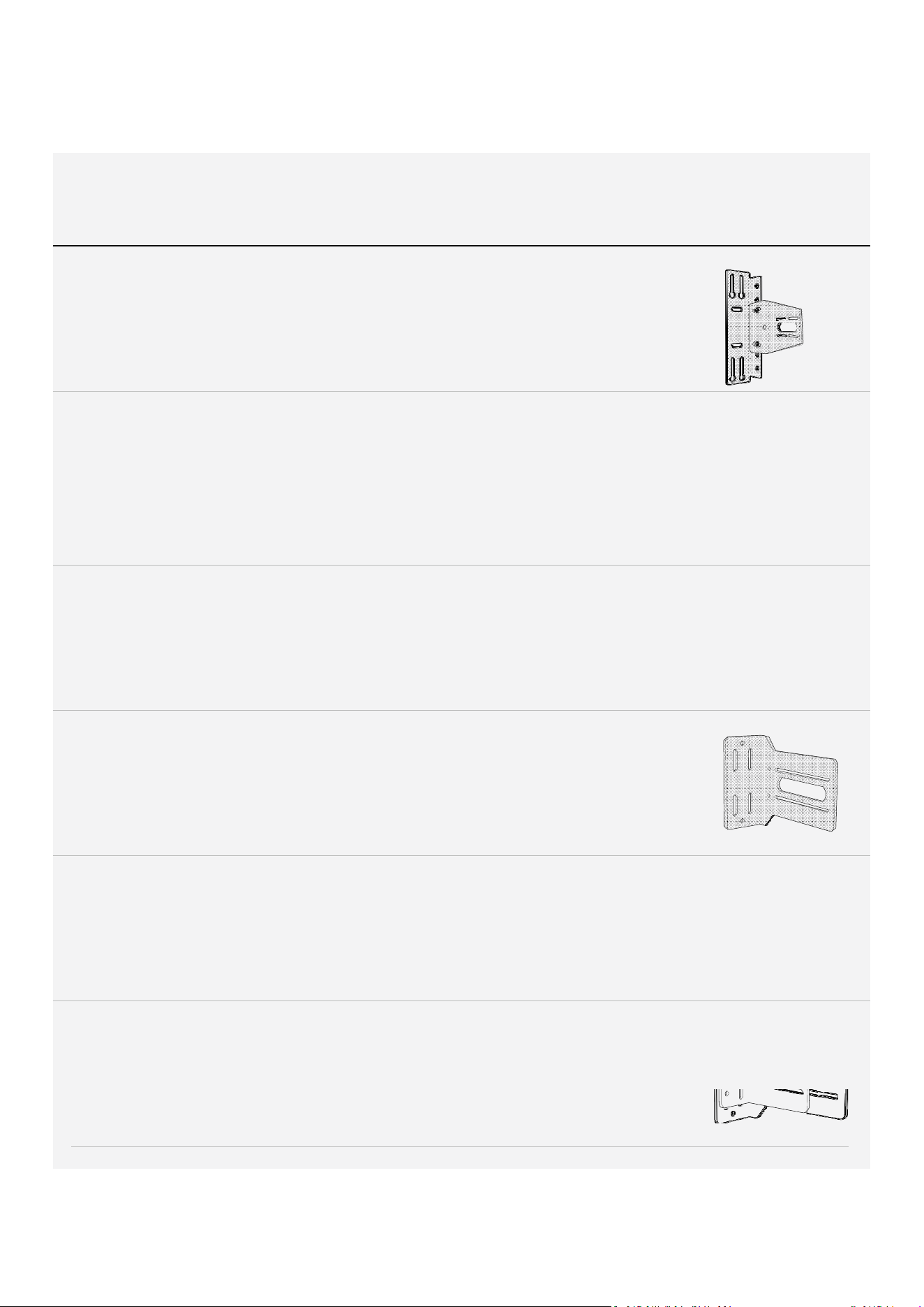
AvailableBrackets
BracketName
DoorType
InstallType
CableDrum
Diameter
Image
HoodMountBracket
Kit+MultifitWall
MountBracketKit
Assembly
PartNo.
101919&101900
RollingSteel,Roller
Shutter,
OverheadDoor
•
SprockettoSprocket,
•
HeavyDutymountingoption,
•
Loadspreadingforpoor
substrate,
•
Retrofittoexistingoperator
mountingfootprint
N/A
MultifitWallMount
BracketKit
PartNo.
101919
RollingSteel,Roller
Shutter
•
SprockettoSprocket,
•
HeavyDutymountingoption,
•
Loadspreadingforpoor
substrate,
•
Retrofittoexistingoperator
mountingfootprint
N/A
HoodMountBracket
Kit
PartNo.101900
RollingSteel,Roller
Shutter,
•
SprockettoSprocket
N/A
WallMountBracketKit
(longbracketonly)
PartNo.101910
Sectional,
OverheadDoor,
VerticalLift,
HighLift
•
DirectShaftCoupling
•
SprockettoSprocket
6”‐14”
WallMountBracketKit
(shortbracketonly)
PartNo.101910
Sectional
OverheadDoor,
VerticalLift,
HighLift
•
DirectShaftCoupling
•
SprockettoSprocket
4”‐7”
WallMountBracketKit
(stackedshort&long
brackets)
PartNo.101910
Sectional
OverheadDoor,
VerticalLift,
HighLift
•
DirectCoupling
•
SprockettoSprocket
•
HeavyDutymountingoption
6”‐14”
32
DAVECommercialDoorOperator—InstructionalManual
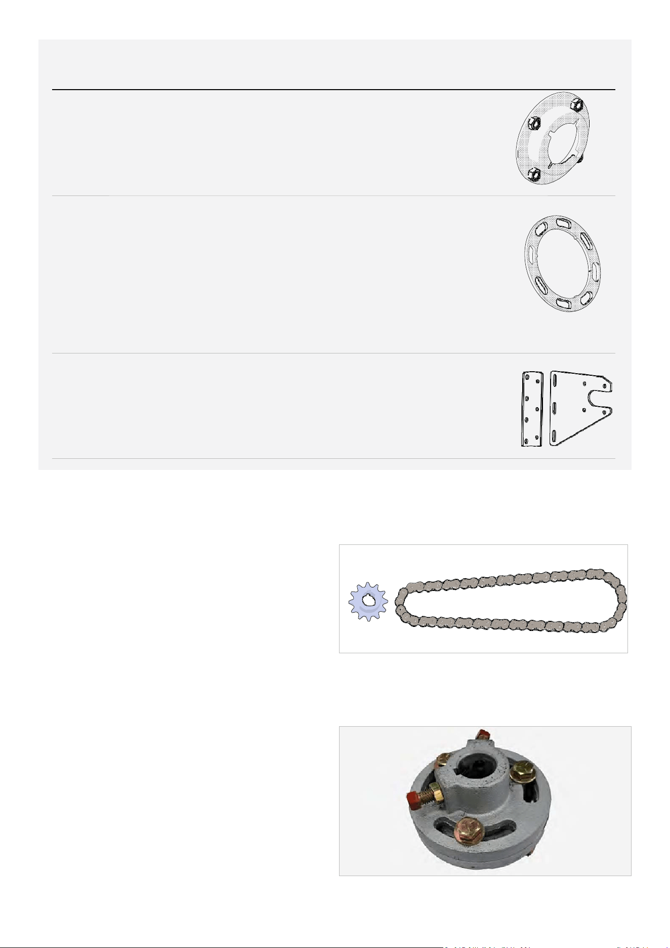
DriveSetup
1
0
B
(
#
5
0
)
S
P
R
O
C
K
E
T
A
N
D
C
H
A
I
N
ConnectsDAVE’sdriveshaftwithdoorsprocketinsprocket
tosprocket(jackshaft) installations.
StandardDriveKitReplacementforDAVEPartNo.101948
Fig:16
SHAFTCOUPLER(SOLDSEPARATELY)
CouplesDAVE’sdriveshaftwithsectional,high‐liftand
verticalliftdoorshaftsindirectdriveinstallations.
AvailableinAustraliaandNewZealandonly
1
”
t
o
1
”
C
o
u
p
l
e
r
(
C
F
1
00
)
‐
P
a
r
t
N
o
.
1
0
222
0
1
”
t
o
1
.
25
”
C
o
u
p
l
e
r
(
C
F
1
0
5
)
‐
P
a
r
t
N
o
.
1
0
222
1
Fig:17
BracketName
DoorType
InstallType
CableDrum
Diameter
Image
Flanged
MountingAdaptor
RollingSteel(Steel
RollerShutter)
•
•
IncludedinPartNo.
101510only
SprockettoSprocket
Retrofittoexistingroller
shuttermount(commonin
Australia&NewZealand)
N/A
MountingBracket
Spacer
SectionalDoors
andNorth
Americantypelive
axleRollingSteel
Doors.
•
•
•
•
SprockettoSprocket, N/A
DirectCoupling
Usewithsectionalandhood
mountbrackets
AnyinstallwhereDAVE’S
gearboxismountedagainsta
flatsurface.
DONOTUSEWIITHANZ
FLANGEDMOUNTING
ADAPTOR
ShutterMounting
BracketKit
PartNo.62622
AvailableinAustralia
only.
RollingSteel(Steel
RollerShutter)
•
SprockettoSprocket
N/A
33
DAVECommercialDoorOperator—InstructionalManual
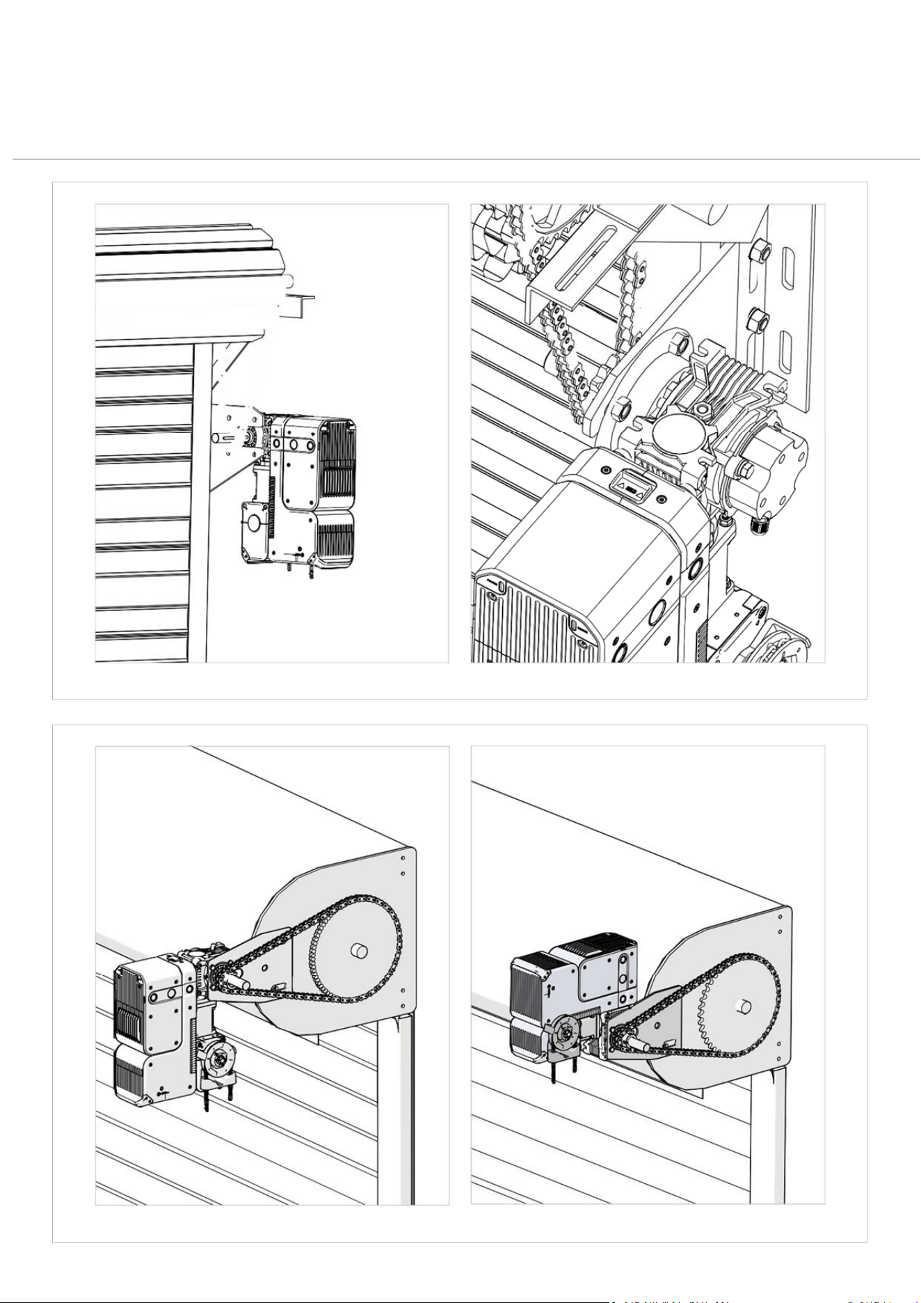
MountingOptions
Fixed Axle Roller Shutter with Flanged Mounting Adaptor - common in AU / NZ
Hood Mount Variations Using Hood Mount Bracket Common in North America
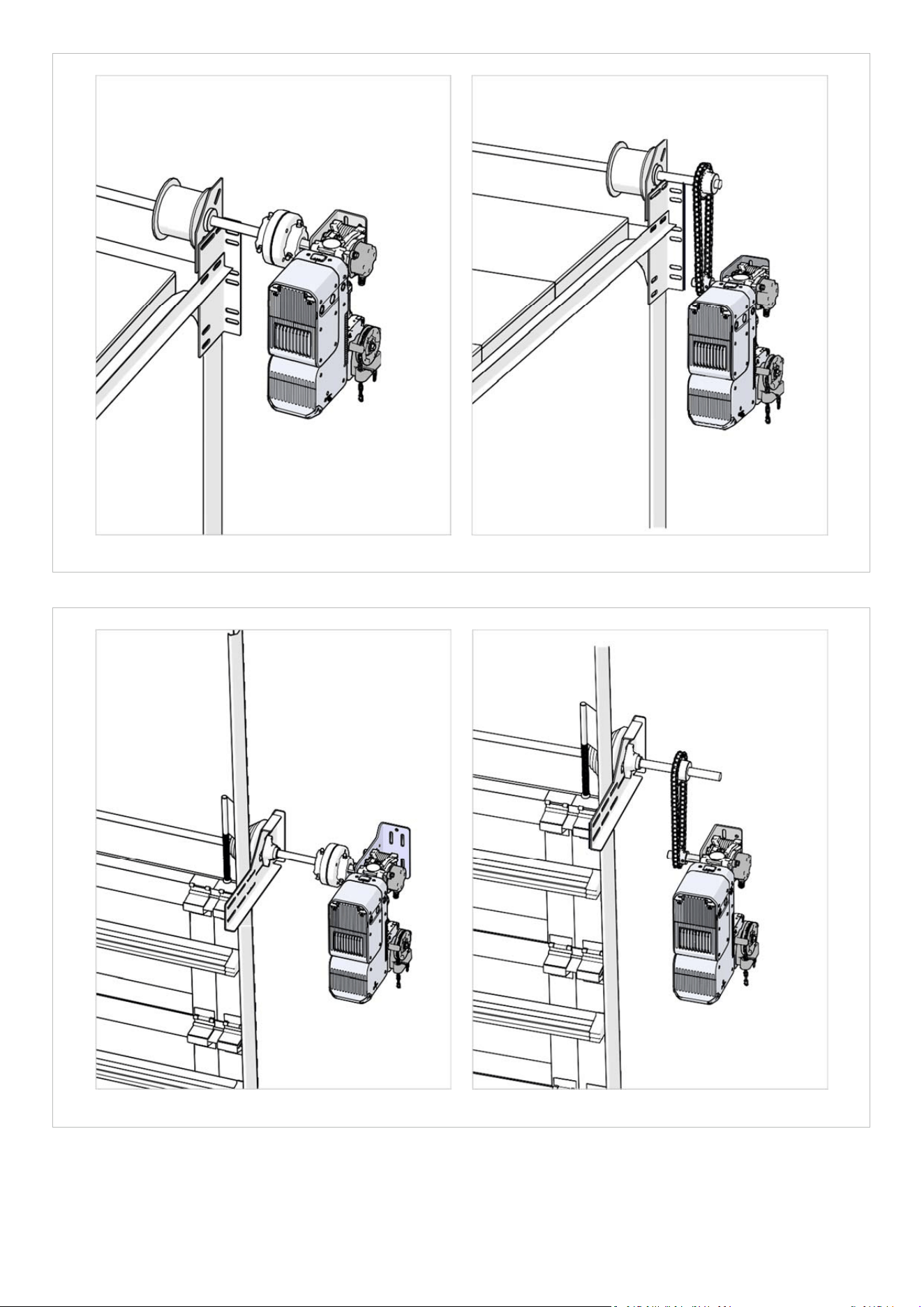
34
DAVECommercialDoorOperator—InstructionalManual
Positionsprocketascloseto
doorbracketaspossible
Standard Sectional Door Installation with Direct Coupling Adaptor and Short Standard Sectional Door Installation with Sprocket to Sp r oc ke t Dr i ve a nd
Sectional Bracket Short Sectional Bracket
Positionsprocketascloseto
doorbracketaspossible
High Lift and Vertical Lift Sectional Door Installation with Direct Coupling High Lift and Vertical Lift Sectional Door Installation with Sprocket to
Adaptor and Long Sectional Bracket Sprocket Drive and Short Sectional Bracket
Shortandlongwallmountbracketscanbe
stackedifrequiredtoprovideadditionalsupport
forheavydoorinstallations.
35
DAVECommercialDoorOperator—InstructionalManual
WallConsole
Connectivityoptions
DAVEisawireless‐firstsolution.So,unlessyou’vegotathingforwires,awireless
installconfigurationisthewaytogo..
SeePairingWallConsoleonpage49andConnectingConsoletoOperatorBy
Cableonpage37forfulldetails.
Poweroptions
Thewallconsolecanbepoweredinoneofthreeways:
1.
Batteries:
2x1.5VTypeDAlkalinebatteries.
2.
5VDCPower:
Viathe5VDCjack(powersupplynotincluded).
3.
OperatorPowered:
Throughthe4corewallconsolecable(PartNo.
102189.Soldseparately).
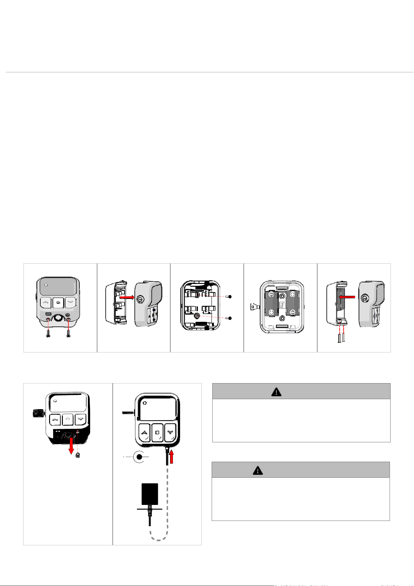
MountConsoletoWallwithAppropriateFastenersandInsert Batteries
Connecting5vDCpowersupply
+
DC5V
Remove the port cover from the
connector port
Warning
Batteriesmustberemovedfromconsolebefore
connectingeither5vDCpowersupplyorcablefrom
powerhead.Donotusebatteriesifusingalternatepower
sources.
Avertissement
Lespilesdoiventêtreretiréesdelaconsoleavantde
connectersoitl’alimentation5VCC,soitlecâbleprovenant
del’opérateur.N’utilisezpasdepilessivousutilisezd’autres
sources d’alimentation.
36
DAVECommercialDoorOperator—InstructionalManual
nu
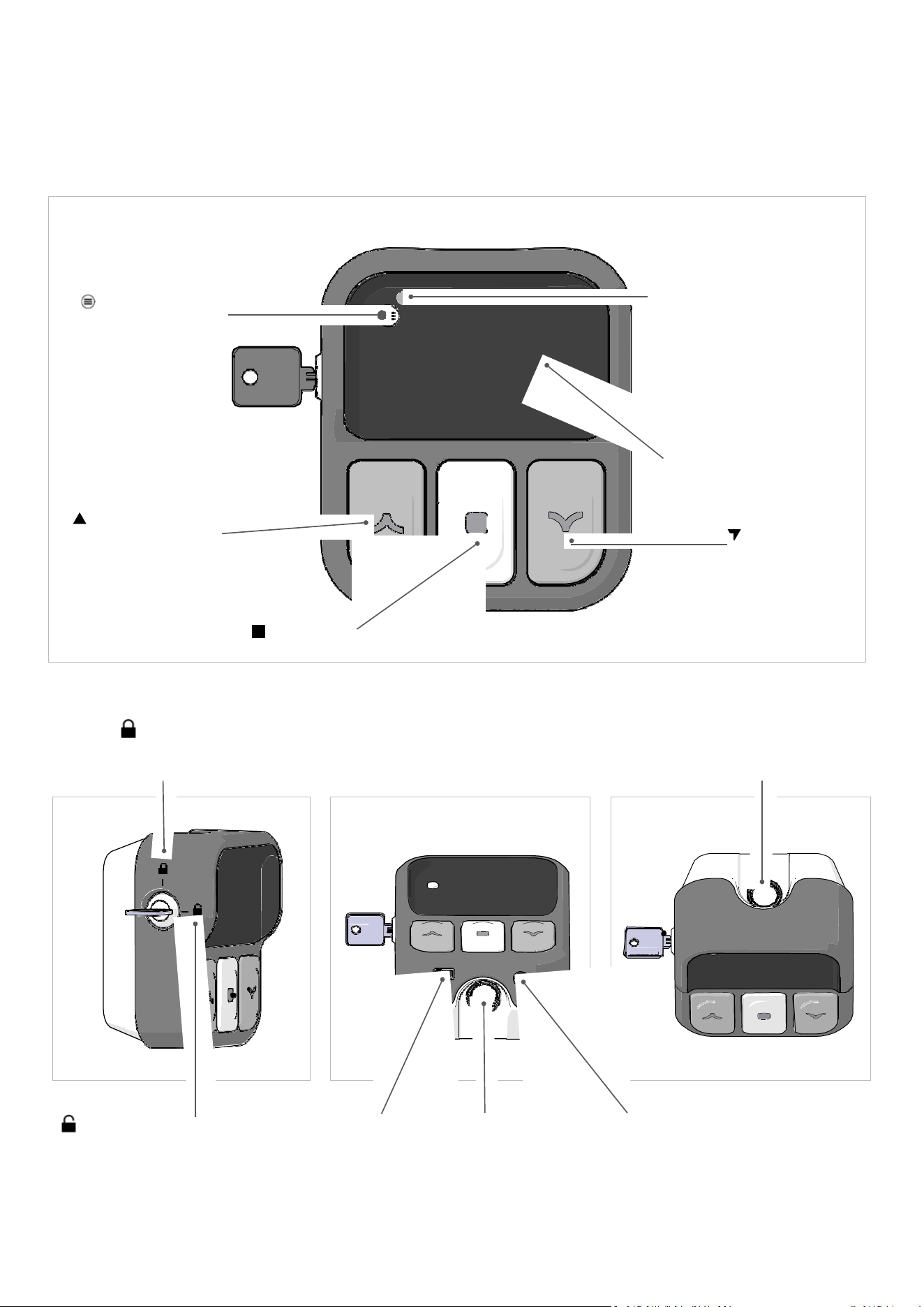
ConsoleOperatingControls
MENU
MENUSTATUS
Access/ExitMenu
LED
Litwhenmenuisactive
andconsoleisinedit
settingsmode
Flashing=Attention!
Off=normaloperation
4Linex20Character
BacklitLCD
UP
OPEN,NavigateUpMe
DOWN
CLOSE(Navigate
DownMenu)
STOP
STOP,Select/Set
WirelessWallConsole
LOCKED
Disablemenuaccessto
changesettings
PUNCHOUT
Foroptionalcabled
connectiontooperator
Top
Bottom
UNLOCKED
Enablemenuaccessto
changesettings
PROGRAMMER
PORT
ForPG3programmer
PUNCHOUT
16mm&20mm.
Foroptionalcabled
connectiontooperator
andaccessorywirepass
through.
5VDCJACK
PowerjackforoptionalDCpower
supply
37
DAVECommercialDoorOperator—InstructionalManual
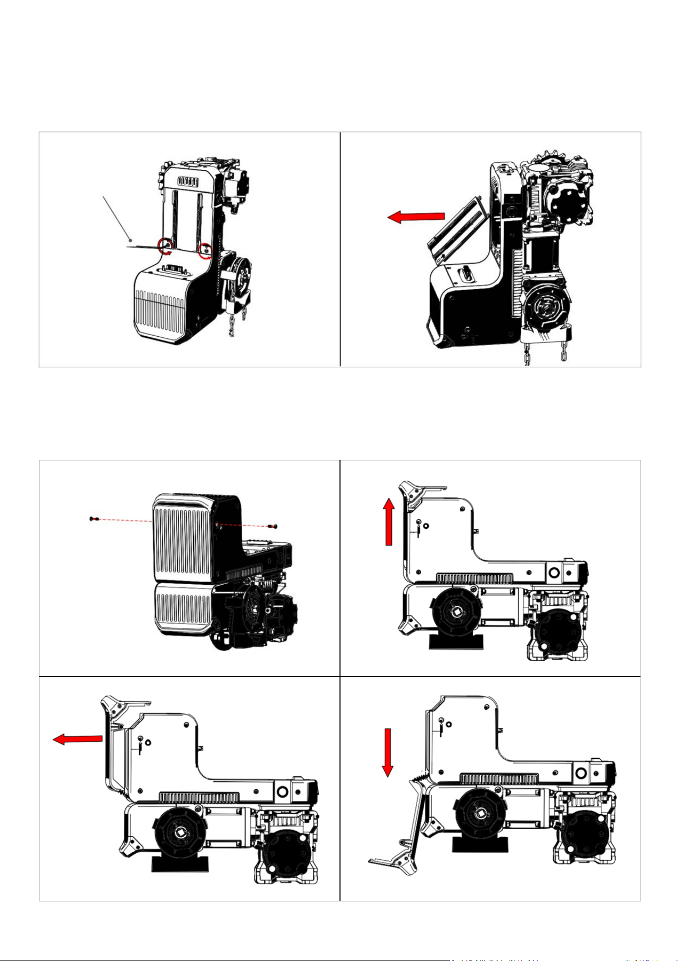
ConnectingConsoletoOperatorByCable
RemovingInternalCableConduitCover
2.5mmAllen(Hex)Key
RemovingMainControlBoardAccessCover
Fig:18
Fig:19
Fig:20
Fig:21
38
DAVECommercialDoorOperator—InstructionalManual
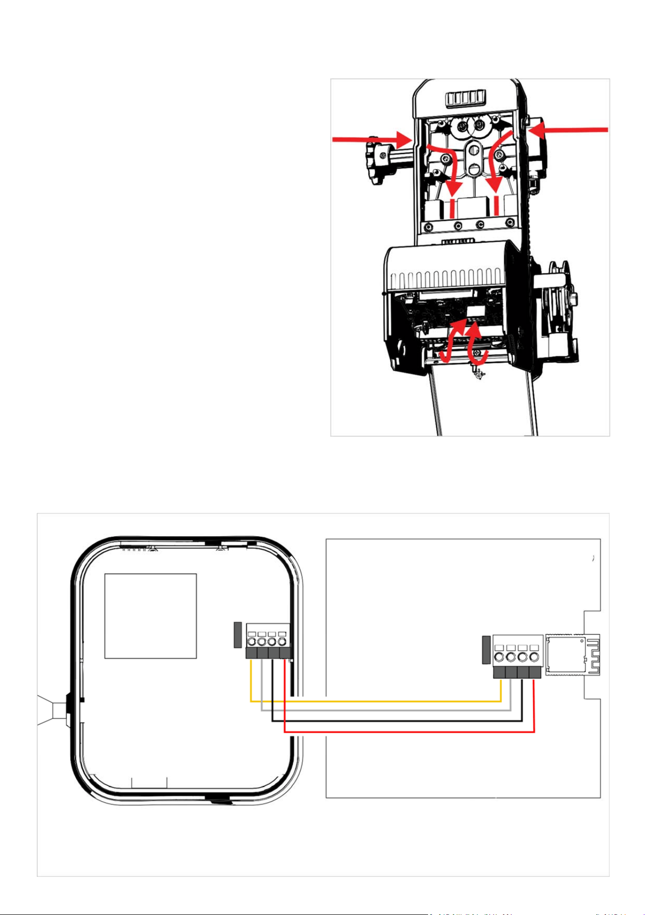
WiringPathforConsoleandAccessories
•
Choosethebestapproachandsideofentryintothe
operatorforwiring.Tominimiseriskofentanglingcables
withtheDAVE’sdrivemechanism, thiswillbetheopposite
sidetothedriveshaftanddoorinmostcircumstances.
Wiringpunch‐outsarelocatedonbothsides,asshownin
Fig:22.Removepunch‐outonyourchosenside.
•
Unfastencoverusing2.5mmAllen(hex)keyandremove.
•
Unfastencaptivescrewstoopenreardoor.
•
Feedcablethroughpunch‐out,wiringchannelandinto
maincontrolboardaccesscompartment‐
seeFig:23.
Fig:22
ConnectingConsoleandControlBoardTerminals
COLOURCODE
Fromlefttoright
B=Yellow
A=White
0V=Black
5V=Red
BA0V5V
BA0V5V
Fig:23
CONSOLEWITH
BACKCOVER
REMOVED
MAINCONTROL
BOARD
OPN
OPENER
C
ONSOLE
39
DAVECommercialDoorOperator—InstructionalManual
WarningPlacards
I
n
cl
u
d
ed
i
n
p
a
r
t
N
o
.
1
0
1
5
11
(
N
o
r
t
h
Amercia)only
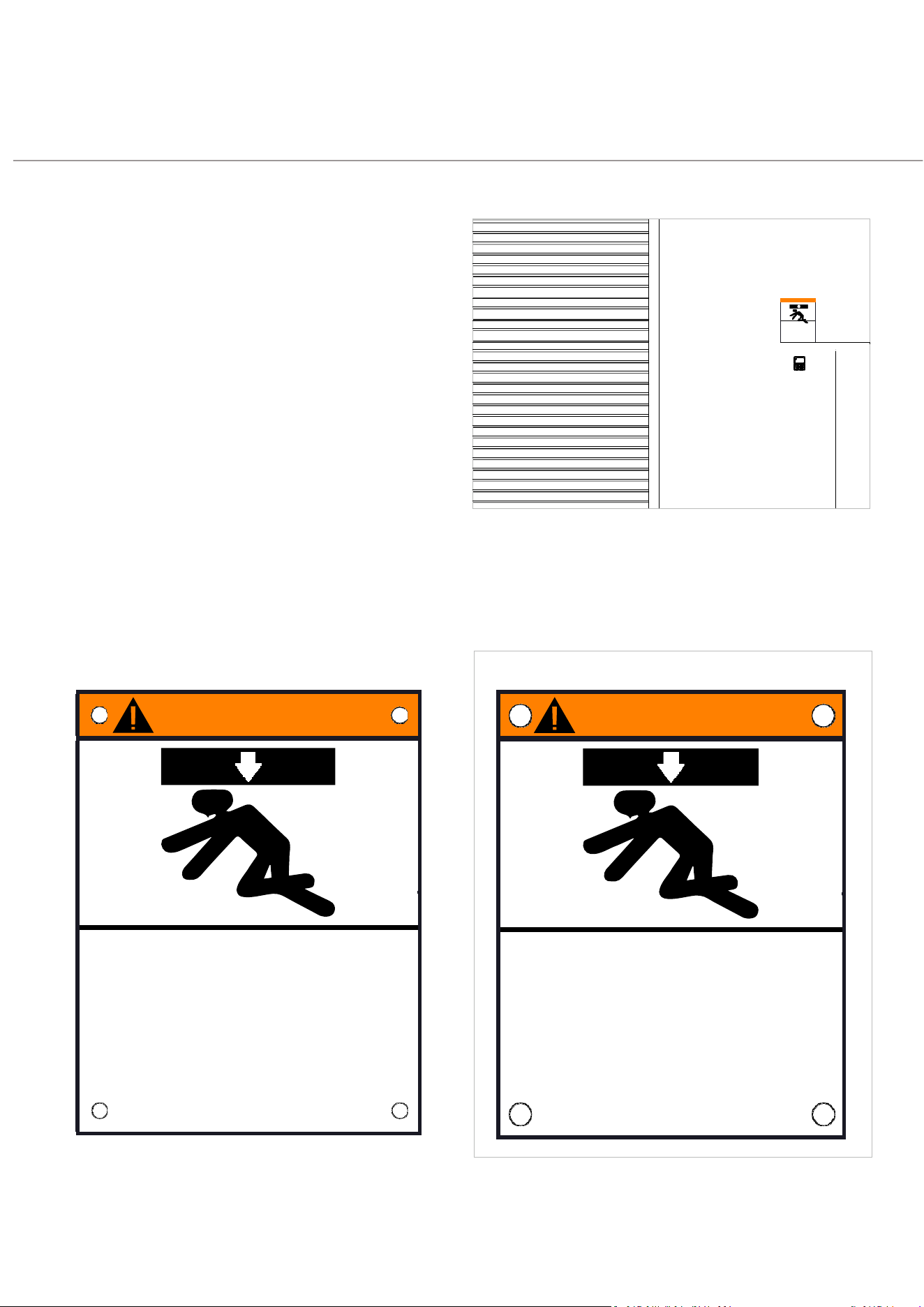
Entrapmentwarningplacardsmustbe
installedonallinstallationsintheUnited
StatesandCanada.
AFrenchlanguageversionoftheplacardis
suppliedforuseinCanada,wherebilingual
safetywarningsaremandatory.
Attachtheentrapmentwarningplacardon
thewallnearthedoorcontrolwithtacks
orstaplesataminimumheightof5feet
(1.53metres)abovefloors,landings,steps
orotheradjacentwalkingsurfacesoshall
childrenarenotabletoreachit.
DonotremoveorpaintoverthesePlacards
WARNING
Moving Door Can Cause
Serious Injury or Death
Keep Clear! Door May Move at any Time Without
Prior Warning
Do Not Let Children Operate the Door or Play
in the Door Area
Keep Door in Sight at all Times When Door is Moving
AVERTISSEMENT
La porte en mouvement peut
causer des blessures graves
ou la mort
Restez à l’écart de la porte. Celle-ci peut être active
à n’importe quel moment sans avertissement.
Ne laissez pas les enfants manœuver la porte ou
jouer dans la zone de la porte
Gardez la porte en vue en tout temps lorsqu’elle est
en mouvement
Keep Doorin Sight at all
WARNING
PLACARD
MUSTBE
ATLEAST5’
(1.53M)FROM
FLOOR

40
DAVECommercialDoorOperator—InstructionalManual
5.
CONNECTINGTOPOWER
41
DAVECommercialDoorOperator—InstructionalManual
EMERGENCYSTOPREQUIREMENT
•
Anemergencystopbuttonmustbepermanentlywiredintothemains(electrical)powersupplyfortheopeneror
operator.
•
Whenpressed,theemergencystopmustimmediatelyoverrideallotherfunctionsandbringthesystemtoa
safestopwithoutcreatinganynewhazards.
•
Theemergencystopmustnotcausethesystemtorestartautomaticallyunderanycircumstances.
EXIGENCED’ARRÊT D’URGENCE
•
Unboutond’arrêtd’urgence
doitêtrecâblédefaçonpermanente
àl’alimentationprincipaledel’opérateur.
•
Lorsqu’ilestactionné,l’arrêtd’urgence
doitimmédiatementneutralisertouteslesautresfonctions
etamenerlesystèmeà
unarrêtsécurisésanscréerdenouveauxdangers.
•
L’arrêtd’urgence
nedoitenaucuncasprovoquerunredémarrageautomatiquedusystème.
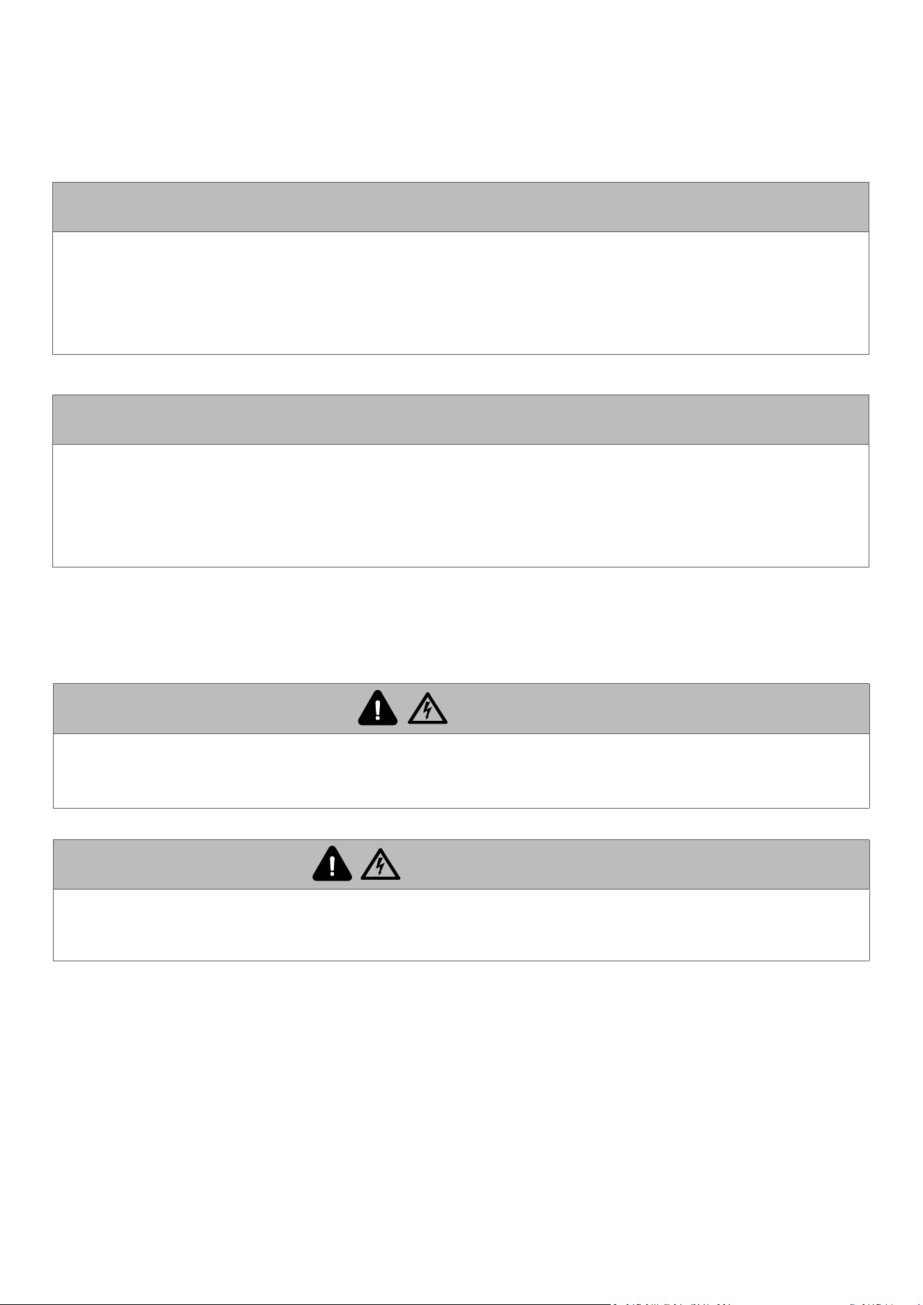
WARNING
Ifusingawiredconnectionbetweenconsoleandoperator,donotturnthepoweronto
theoperatorbeforeconnectingtheconsole.
AVERTISSEMENT
Sivousutilisezuneconnexionfilaireentrelaconsoleetl’opérateur,nemettezpas
l’opérateursoustensionavantd’avoirconnectélaconsole.
42
DAVECommercialDoorOperator—InstructionalManual
OmniVolt®PowerCartridge
Details
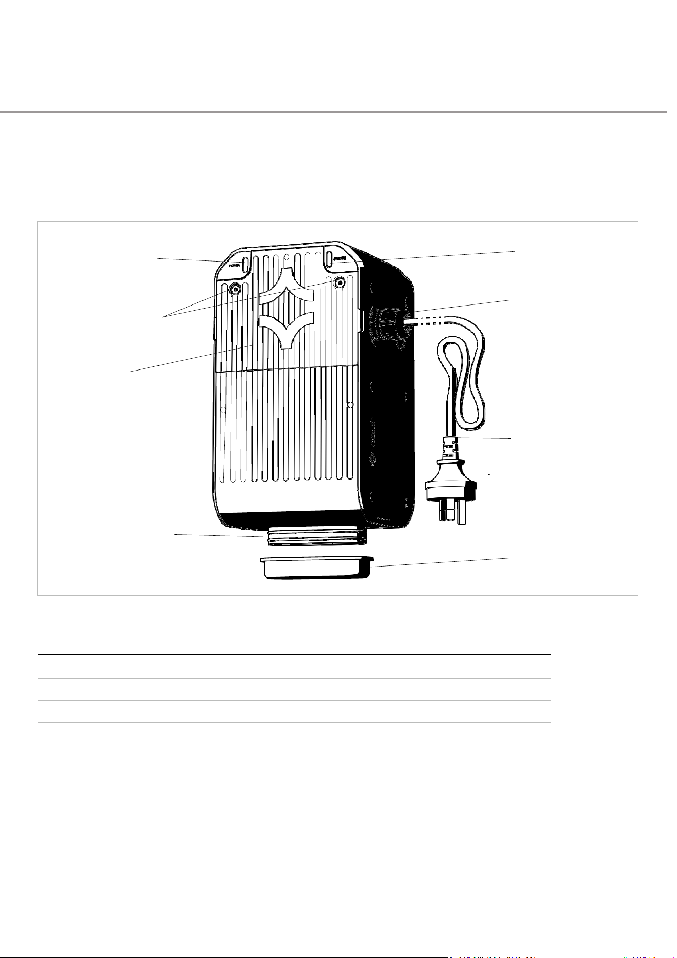
PowermustbesuppliedtoDAVEbyanOmniVolt®powercartridge
(soldseparately).PleasefollowyourOmniVolt®instructionguidefor
configurationinformationandspecifications.
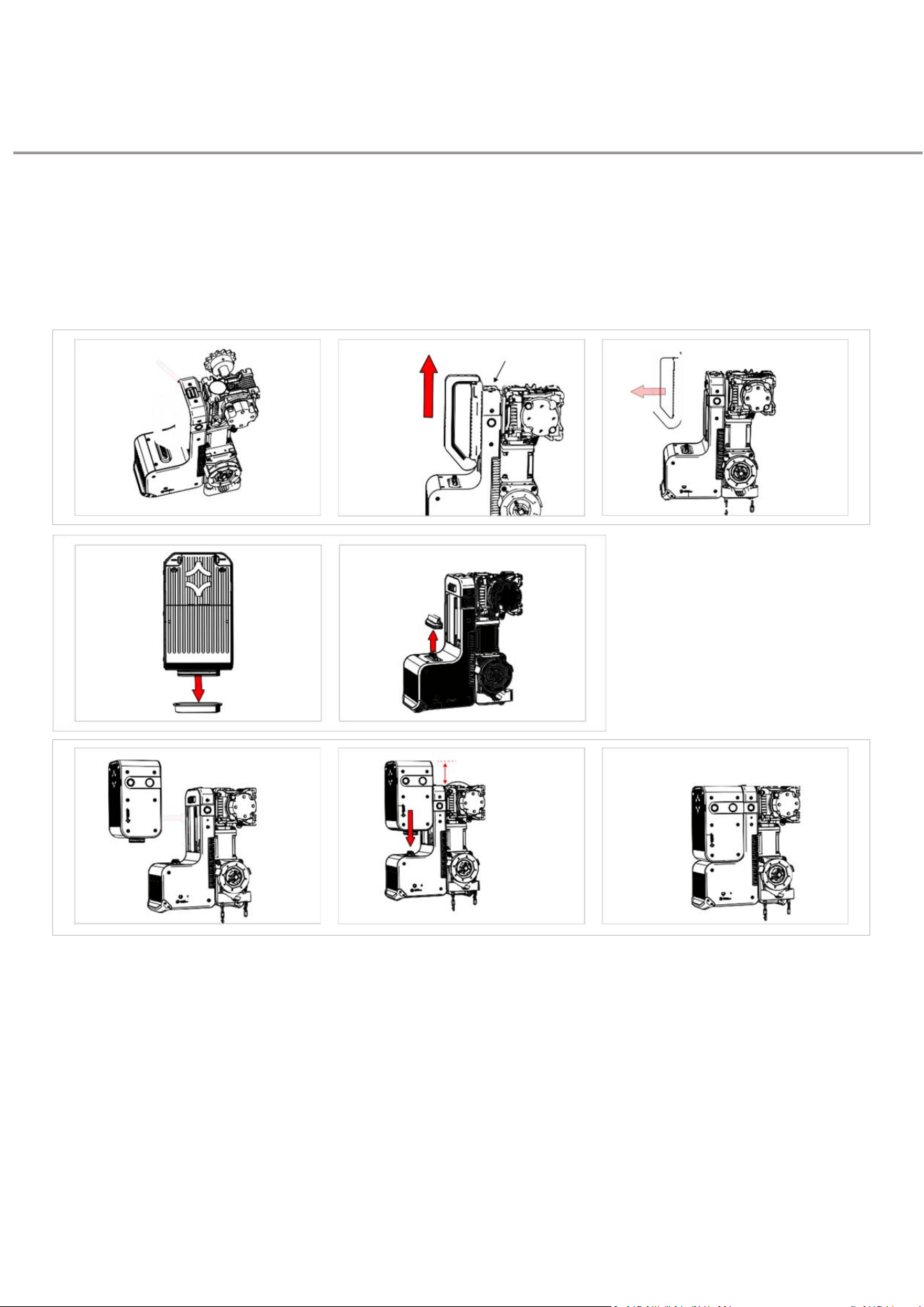
StatusLED
PowerLED
(Blue)
(Green)
Power
CableGland
AccessCover
Screws
Access
Cover
1.3m(4’3”)
Pre‐wired
PowerCable
andPlug
Power
ConnectionPort
PortCover
Fig:24
OmniVolt®CartridgeOptions
LowVoltage
120‐240vac50/60Hz
PartNo.101641
LowVoltage
230‐240vac50/60Hz
PartNo.101640
HighVoltage
400‐480vac50/60Hz
PartNo.101642
43
DAVECommercialDoorOperator—InstructionalManual
ConnectingOmniVolt®
PowerCartridge
IMPORTANT:IfswappingacurrentlyinstalledOmniVolt®powercartridge,electricalpower
mustbeswitchedoffatthewall(orpowerswitchboardifwiredin)andbothLEDsfully
offbeforeremovingthepowercartridge.Afterswitchingoffelectricalpower,itcantake
severalminutesforthebluestatusLEDtogoout.Failuretofollowthisinstructionmay
permanentlydamagetheoperator’scircuitry.
CartridgeReleaseCatch
≈25‐30mm/1‐1¼”
CLICK
Configurecartridgepowercableconnection
TheOmniVolt®low‐voltagepowercartridgeispre‐wired
witha1.3m(5’)powercableandACplug,withthecableonits
righthandside.
•
LowVoltageCartridge:Ifnopoweroutletiswithinreach,
theLowVoltageCartridgemaybewireddirectlyinto
mainspower(alsoknownaslinepowerinNorthAmerica)
•
HighVoltageCartridge:Thismustbewireddirectlyinto
mainspower(linepower).Itsupportsboththreephase
andsingle‐phaseconnections,aslongasaneutralwireis
present.
FollowtheOmnivoltinstructionguideforguidance.
Dependingonlocalelectricalregulations,anymodification
tothepowercartridge—suchasrelocatingthecableor
wiringdirectlyintomainspower—mustbecarriedoutbya
licensedelectricianorelectricalcontractor.

44
DAVECommercialDoorOperator—InstructionalManual
6.
WIRINGDETAIL
45
DAVECommercialDoorOperator—InstructionalManual
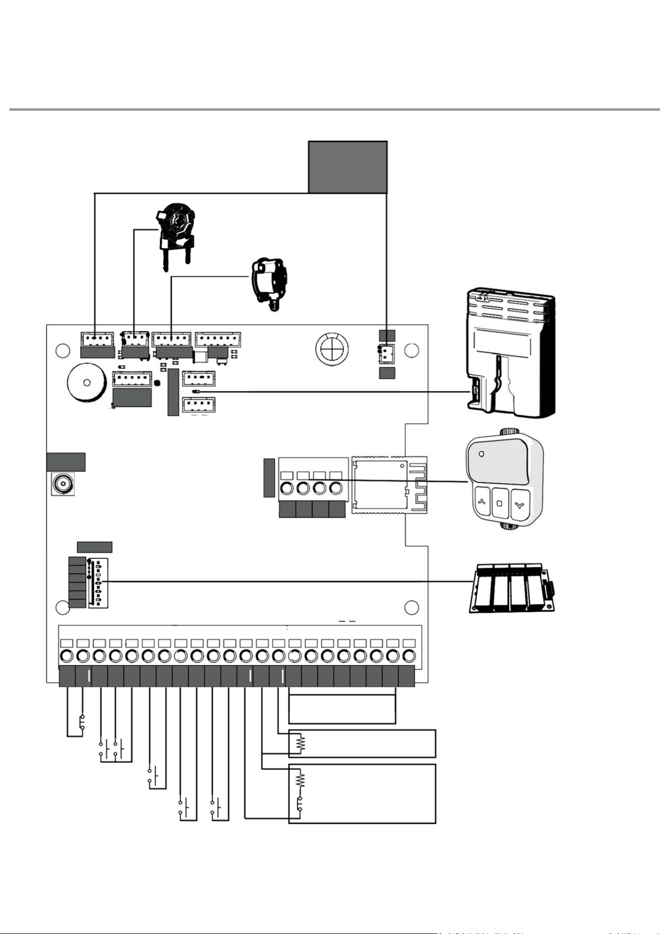
MainControlBoard
Overview
MOTOR
DRIVER
BOARD
DISENGAGEMENT
SWITCH
TIMING
SWITCH
WIRELESSBASESTATIONS
Forwirelesssafetybeaminstallation
MTRCOM CHAIN
POSITION
HUB
0V
24V
NOTIN
USE
REMOTE
ANTENNA
B
A
0V 5V
24V
1
2
3
4
0V
RELAYS
WALLCONSOLE
RELAYMODULE
(SOLDSEPARATELY
)
SafetyDevices
Seeadditionaldiagram
TensionSensor
Remove10Kjumpertouse
Interlock
Remove10Kjumpertouse
GeneralPurposeInputs
N/C=NormallyClosed(PushtoOpen)
N/O=NormallyOpen(PushtoClose)
C
ONSOLE
24V
OV
SD1
OV
SD2
OV
SD3
OV
TEN
OV
INT
0V
GPB
0V
G
PA
OV
OSC
OV
CLS
OPN
STP
0V
Open
/
S
t
op
/
Close
(N/O
)
Open
&
Close
(N/O
)
S
to
p
(N/C
)
R
emo
v
e
Link
t
o
Use
A
C
CESSORIES
46
DAVECommercialDoorOperator—InstructionalManual
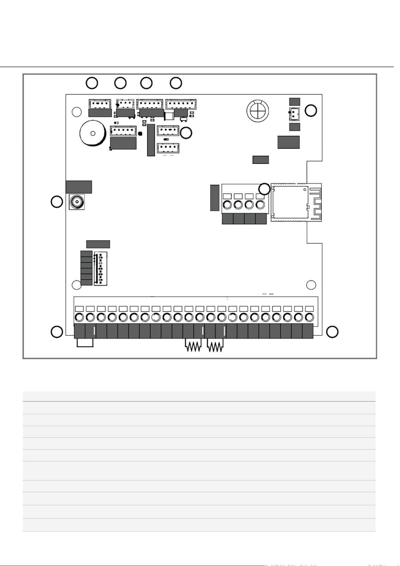
C
ONSOLE
24V
OV
SD1
OV
SD2
OV
SD3
OV
TEN
OV
INT
0V
GPB
0V
G
PA
OV
OSC
OV
CLS
OPN
STP
MainControlBoard
Terminals
6 5 4 3
MTRCOM CHAIN
NOTIN
USE
POSITION
HUB
2
0V
1
24V
REMOTE
ANTENNA
9
7
B
A
0V5V
RELAYS
24V
1
2
3
4
0V
8 8
Fig:25
MAINCONTROLBOARDKEY
KEY
CONNECTORS
DESCRIPTION
1
24V 0V
24V power input to control board
2
ACCESSORIES (2)
BLE base station safety beam connector
3
HUB WiFi device interface
4
POSITION
Door position encoder
5
CHAIN
10K monitored hand operated chain for manual opening and
closing
6
MTR COM
Motor controller
7
REMOTE ANTENNA Remote control receiver antenna
8
EXTERNAL CONNECTOR BLOCK
See table 6.2: top external connector block key
9
CONSOLE Wall console power and communications
LED5
REG
BUTTON
A
C
CESSORIES

47
DAVECommercialDoorOperator—InstructionalManual
TERMINALBLOCKKEY
TERMINAL
TYPE
PURPOSE
STP
0V
NORMALLY CLOSED
Stop control input
OPN
0V
NORMALLY OPEN
Open control input
CLS
0V
NORMALLY OPEN
Close control input
OSC
0V
NORMALLY OPEN
Single button OPEN / STOP / CLOSE control input
GPA
0V
NORMALLY OPEN
General purpose control input A
GPB
0V
NORMALLY OPEN
General purpose control input B
INT
0V
Interlock input - monitored 10K input
TEN
0V
10K
Cable tension input - monitored 10K input
SD1, SD2, SD3
0V
SB/PUL/10K Safety device inputs - SD type selected in settings menu.
Options are:
SB - AT 2 wire 5V safety beam
PUL - monitored 325Hz pulse input
10K - monitored 10K input
24V
0V
24VDC output for powering safety devices and accessories
24 VOLT DC OUTPUT

48
DAVECommercialDoorOperator—InstructionalManual
7
.
SETUP&PROGRAMMING
OPTIONS
49
DAVECommercialDoorOperator—InstructionalManual
PairingWall Console
THEWALLCONSOLEANDDRIVEUNITSHIPPRE‐PAIRED
FROMTHEFACTORY.THEYCANBEUN‐PAIREDANDRE‐
PAIREDIFNECESSARY,OREITHERDEVICEMAYBEPAIRED
TOANALTERNATIVE.
Thedriveunitandconsolerelyontwoseparatechannelsforwireless
communicationwitheachother:
1.
Bluetooth:formessaging,statusupdates,settingschangesetc.
2.
RFLink:foroperatordrivecontrolonly–OPEN,STOP,CLOSEcommands.
Pairingawallconsolewiththedriveunitrequiresseparatepairingstepsfor
BluetoothandRF‐Link.Thesestepsfollowsequentiallyinthesetupprocedure
(Fig:26‐Fig:37)andmustbothbecompletedfortheoperatortofunctionnormally.
NOTE:Awallconsolecanonlybepairedwithonedriveunitatatimeandadrive
unitcanonlybepairedwithonewallconsoleatatime.Therefore,ifreplacinga
console,theoldonemustbeunpaired.
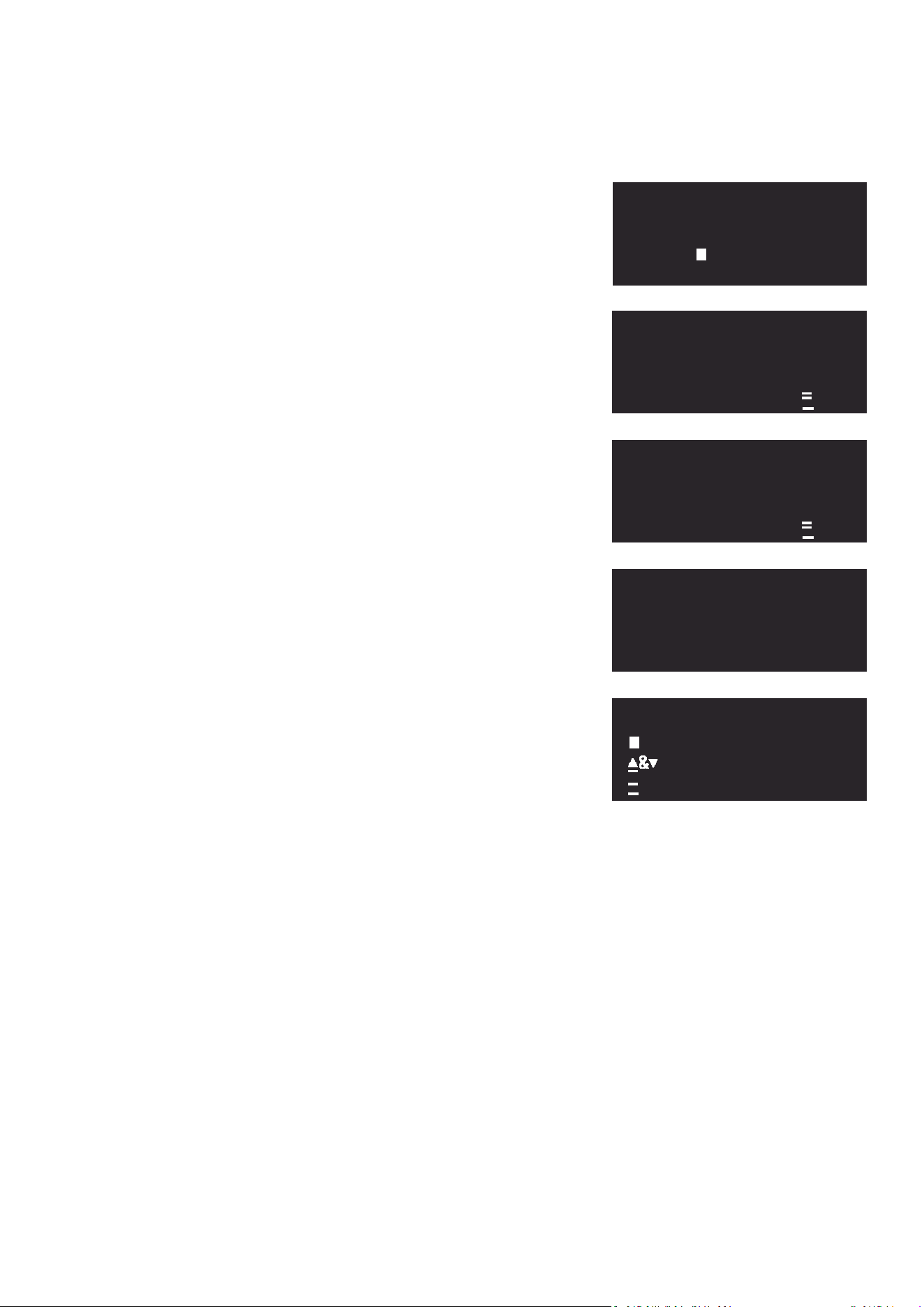
BLUETOOTHPAIRING
1.
OpentheaccessdooronthedriveunitbyunscrewingtwoPhillipshead screws.
2.
Fig:26showsthestartscreenofthepairingwizard.Press
tobeginandfollow
theinstructionsonscreenuptoFig:29.
3.
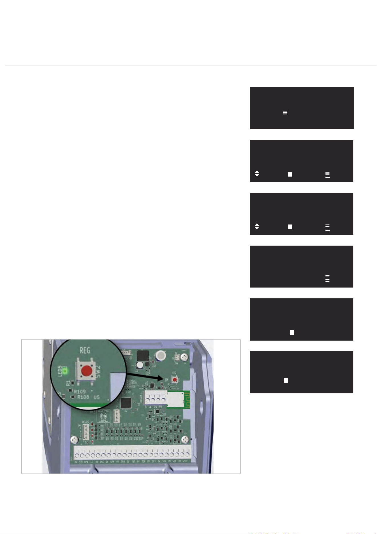
IfthegreenLED5totheleftoftheredREGbuttononthemaincontrolboardislit
(seeFig:32),thedriveunitisreadyforpairing.Ifitisnotlititisalreadypairedtoa
wallconsoleandmustbe unpaired.
TocompletetheBluetoothparingprocess,pressandholdtheredREGbuttonfor
3secondsuntilthegreenLED5startsflashing.Afterflashingforafewseconds
thegreenLED5willgooutandFig:30willdisplay.Press
tocontinueandfollow
theinstructionstocompletetheRFLinkLearningprocessthatfollows.
Fig:26
Fig:27
Fig:28
Fig:29
Fig:30
Fig:31
Fig:32
SETUP REQUIRED
PRESS TO LAUNCH
SETUP MENU
CONSOLE SETUP &
RESET
NEXT
ENTER
EXIT
PAIR CONSOLE TO
OPERATOR
NEXT
SETUP
EXIT
HOLD REG BUTTON ON
OPERATOR FOR 3SEC
UNTIL LED FLASHES
EXIT
CONNECTION SUCCESS,
PROCEED WITH SETUP
NEXT
CONSOLE NOT READY!
PROCEED TO RF LINK
PRESS
TO LEARN.
50
DAVECommercialDoorOperator—InstructionalManual
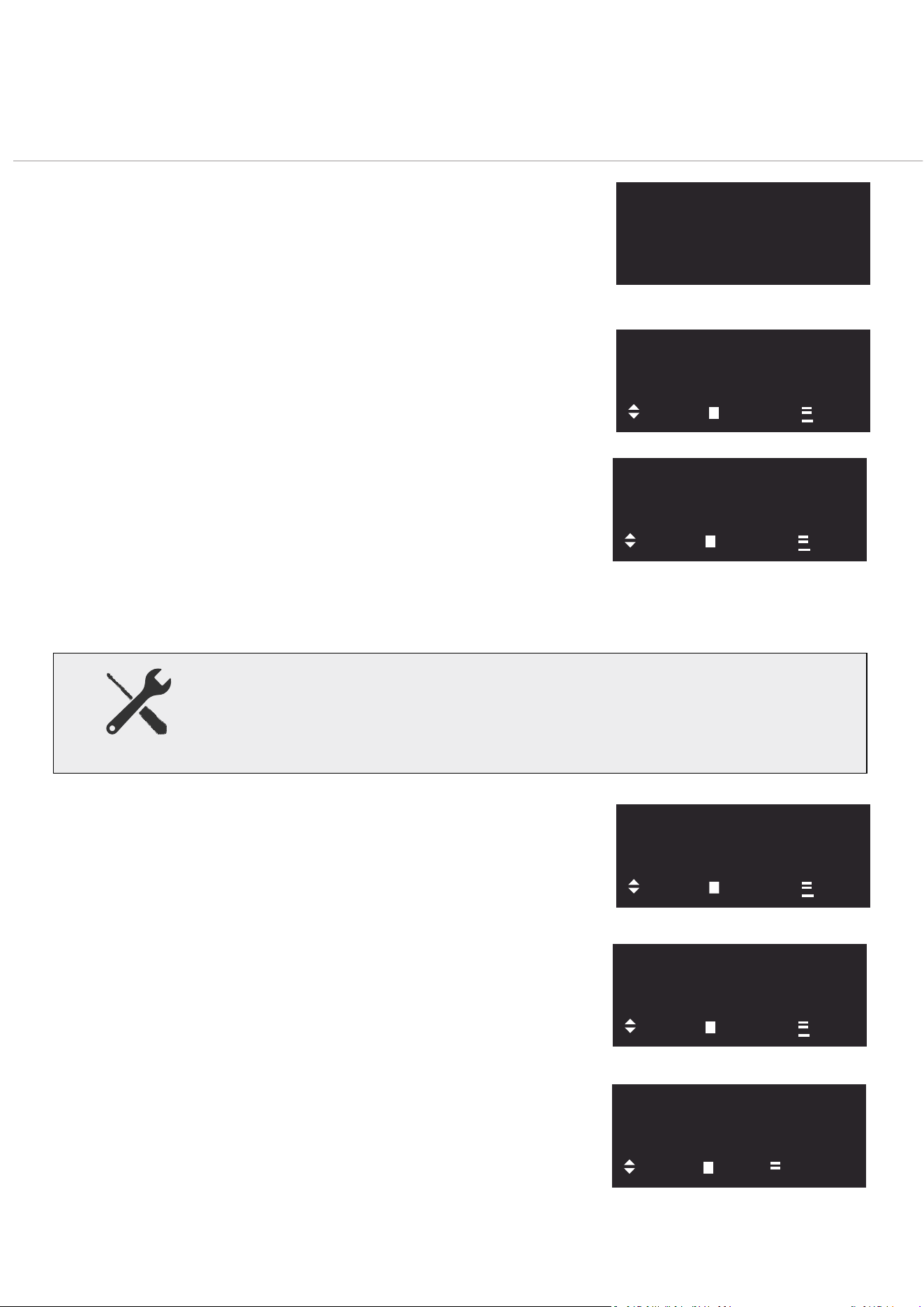
RFLINKLEARNING
TheRFLinkconnectionstepsfollowonsequentiallyafter
c
o
m
p
l
e
t
i
n
g
t
h
e
B
l
u
e
t
oo
t
h
p
a
i
r
i
n
g
s
t
e
p
s
s
h
o
w
n
i
n
Fi
g
:
2
6
‐
Fi
g
:
3
1
.
OnceBluetoothpairinghascompleted,thescreenshownin
Fig:33
willappear.Press
.Fromheretheconsolewillstep
throughthescreensshownin
Fig:34‐Fig:37
withoutanyneed
forinteraction.
DOORWINDUPMODE
Doorwindupmodeisaconvenientutilityforwindingrollingsteel
doorcurtainsontothedrumatinstallationtime.
Whenselected,theconsoleentersdead‐man(constant‐contact)
modeallowingthedrumtobeturnedslowlyineitherdirectionas
required.
Toactivatedoorwindupmode,press
and
simultaneously
w
h
e
n
p
r
o
m
p
t
e
d
f
r
o
m
t
h
e
s
c
r
ee
n
(
Fi
g
:
3
7
)
.
Afterattachingthedoorcurtaintothedrumfollowthe
manufacturer’sinstructionstocompleteinstallation.
Fig:33
Fig:34
Fig:35
Fig:36
Fig:37
CONSOLE NOT READY!
PROCEED TO RF LINK
PRESS
TO LEARN.
LEARNING CONSOLE!
DON’T TOUCH BUTTONS
STARTING...
EXIT
LEARNING CONSOLE!
DON’T TOUCH BUTTONS
CONFIRMING...
EXIT
CONSOLE REMOTE
BUTTONS STORED
NO TRAVEL LIMITS SET
SETUP LIMITS
DOOR WINDUP MODE
ACCESS MENUS
51
DAVECommercialDoorOperator—InstructionalManual
WallConsolePowerModes
DAVE’swallconsolesupportsthreepowermodestosuitdifferent
installationtypesandpowersources.Eachmodeaffectshowand
whentheconsolewakesup,helpingbalanceresponsivenesswith
powerefficiency.
NOTIFY[HIGHPOWER]
•
Wakesuponanychange,includingactionsfromremotesorother
controlsources.
•
Highestpowerusagemode.
•
Recommendedonlywhenusing:
–
5VDCmainspowersupply,or
–
DirectwiredconnectiontoDAVE.
INTERACT[BALANCED]
•
Wakesuponlywhentheconsoleisused.
•
Offersabalancedpowerconsumption.
•
Suitableformostsetups,includingbatterypowered(with
moderateusage).
SLEEP[POWERSAVER]
•
Wakesuponlywhenthe
MENU
(
)buttonispressed.
•
DoesnotwakeforUp,Down,orStop actions.
•
Bestmodeformaximisingbatterylife.
Fig:38
Fig:39
Fig:40
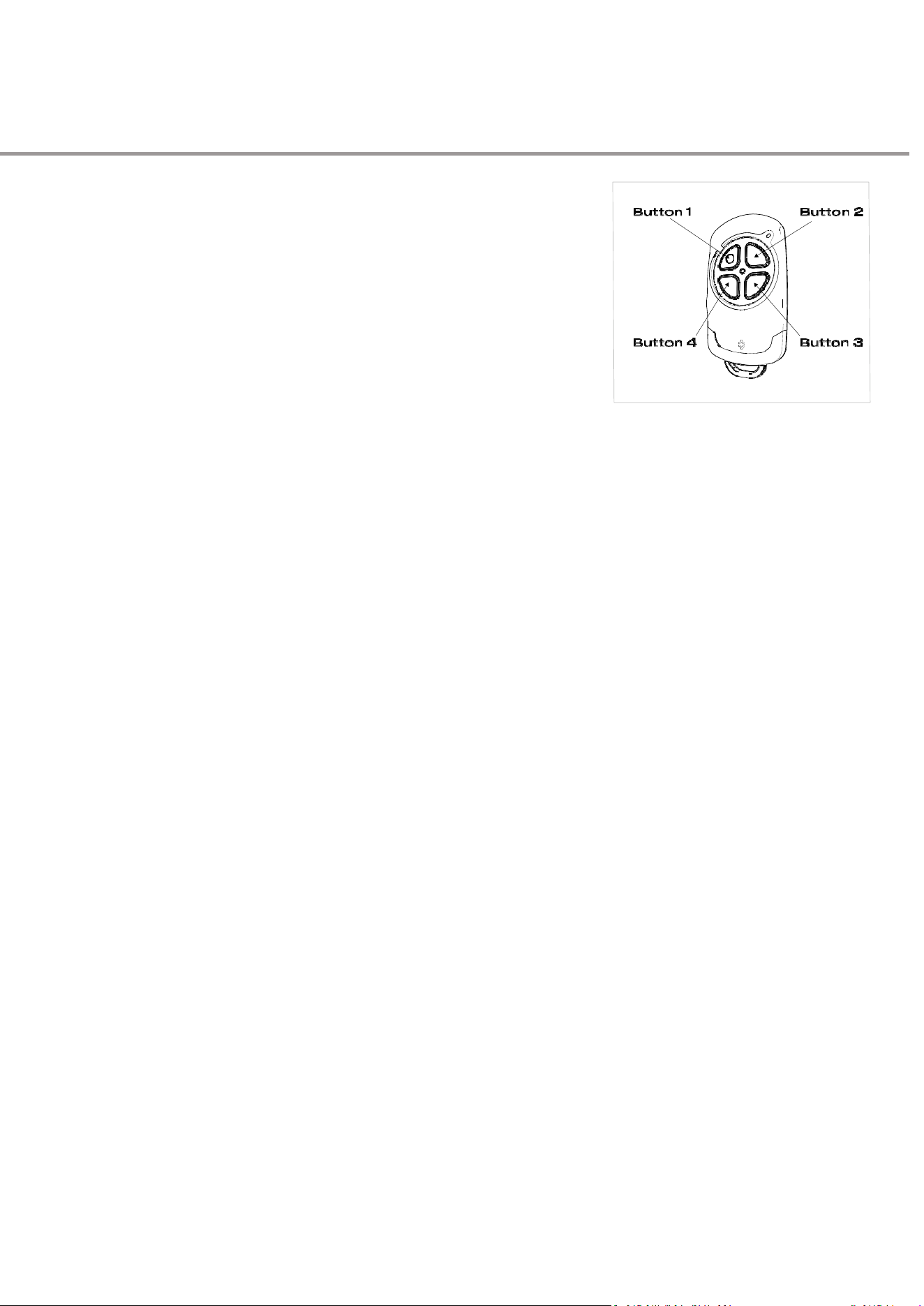
CHANGINGWAKEMODE
SETTINGS
1.
ActivatetheConsole
Iftheconsolescreenisoff,press
MENU
(
).Ifitremainsoff,check
thepowersource.
2.
UnlocktheKeySwitch
Thekeyswitchmustbeunlockedtoproceed.Iflocked,theconsole
willpromptyou(Fig:38).
3.
AccessConsoleSettingsMenu
Press
MENU(
)
rep eate dlyu ntilFi g:3 9app ears. From her etogg le
throughthemenuusing
or
toreachFig:40.Use
t o access
theConsoleSettings.
4.
EditConsoleSettings
AtFig:41press
.Thenextscreen(Fig:42)showsthecurrentWake
Modesetting,whichinthisexample,isNOTIFY.Press
tochange
thesetting.Fig:43showstheeditscreenanddisplaystheeditable
settingUse
or
totogglethroughthe3optionsand
tosavea
newoption.
Fig:41
Fig:42
Fig:43
IMPORTANTTECHNOTE
ContinuousflashingfromthewallconsoleLEDindicatesthatanimportantsystemalert
hasbeentriggered.IftheconsolepowermodeissettoINTERACTorSLEEP,please
pressMENU
(
)
toreviewthealert,astheLCDscreendoesnotwakeupautomatically.
ACTIVATE KEY SWITCH
TO ACCESS LIMIT
SETUP & MENUS
1: REMOTE CONTROL
LEARN MENU
NEXT
START
EXIT
4:CONSOLE
MENU
NEXT
ENTER
EXIT
WAKE MODE
NOTIFY
NEXT
EDIT
EXIT
NOTIFY [HIGH POWER]
WAKE ON ANY
CHANGE
VALUE
SAVE CANCEL
4:CONSOLE
SETTINGS
&
INFO
MENU
NEXT
ENTER
EXIT
52
DAVECommercialDoorOperator—InstructionalManual
UsingRemoteControls
(Transmitters)
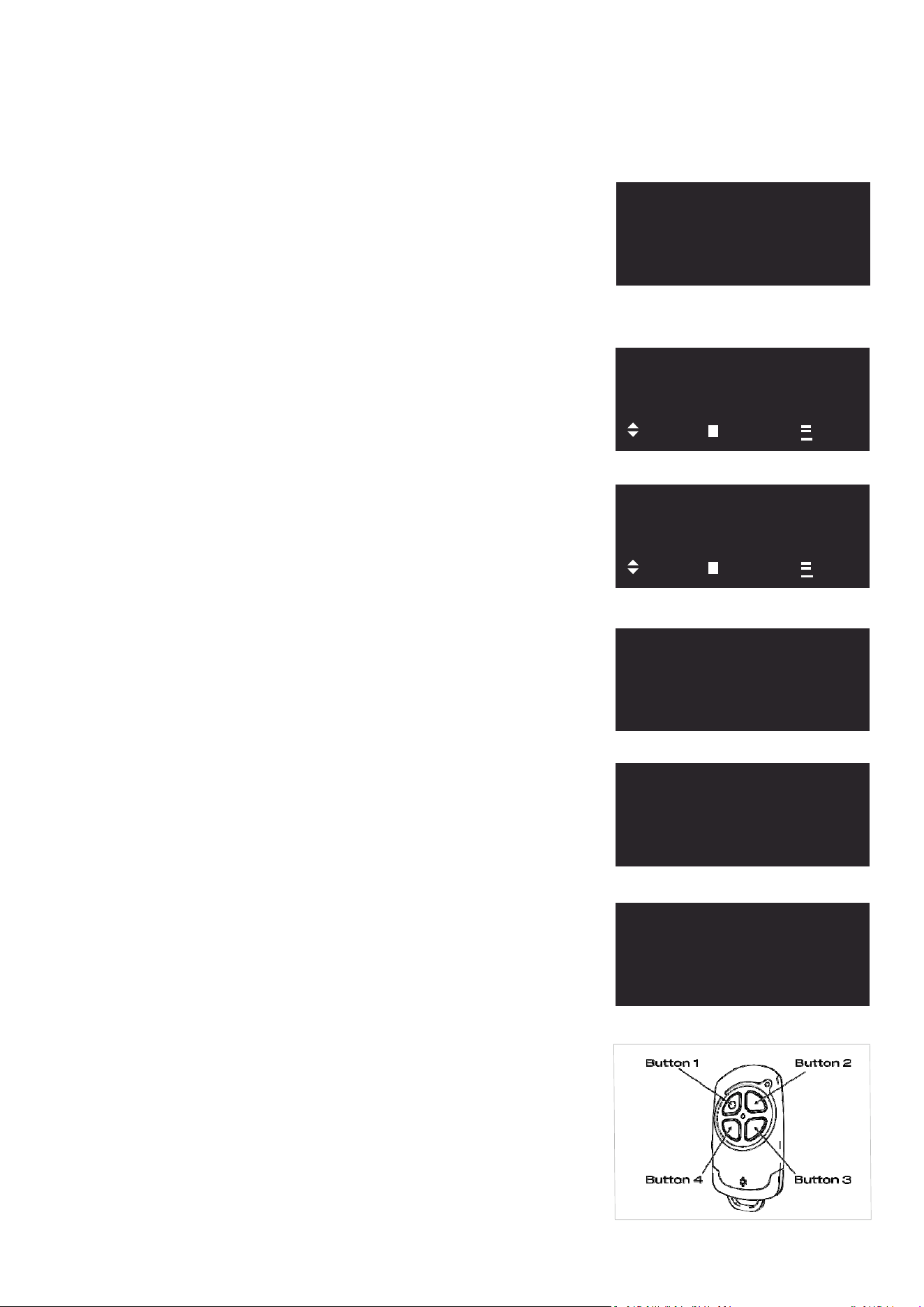
DAVEcanstoreupto63remotecontrolsinitsmemory.
Important:OnlytheAutomaticTechnology4ButtonRemote
(PartNo.102335)iscompatiblewiththissystem(see
Fig:44).
Eachbuttononaremotecanbeprogrammedtoperformadifferentfunction.
Thedefaultsetupsequence,asdescribedinLEARNINGAREMOTECONTROL
(TRANSMITTER)onpage54,assignstheNormalOperationfunctiontoa
singlebuttonoftheuser’schoosingduringthesetupsequence.
Youcanalsoassignabuttontoperformadedicatedfunctiononly,suchasjust
opening,justclosing,orturningonalight.SeeAvailableFunctionsbelowfora
completelistoffunctionsthatcanbeassignedtoanybutton
AVAILABLEFUNCTIONS
NormalOperation
•
O
P
E
N
/
S
T
O
P
/
C
L
O
S
E
:
O
n
e
b
u
tt
o
n
c
y
c
l
e
s
t
h
r
o
u
g
h
t
h
e
c
o
mm
a
n
d
s
i
n
thisorderOpen→Stop→Close
DedicatedFunctions
•
O
PE
N
:
O
p
e
n
s
t
h
e
d
oo
r
o
n
l
y
.
•
S
TO
P
:
S
t
op
s
t
he
do
or
m
o
v
eme
n
t
on
l
y
.
•
CLOSE
:
Closesthedooronly.
•
P
A
R
T
I
A
L
O
P
E
N
:
O
p
e
n
s
t
h
e
d
oo
r
t
o
a
s
e
c
o
n
d
a
r
y
li
m
i
t
p
o
s
i
t
i
o
n
.
•
REMOTELOCKOUT:
Disablesallstoredremotecontrols.
•
A
UX
I
L
I
A
R
Y
OU
T
P
U
T
:
(
r
e
q
u
i
r
e
s
r
e
l
a
y
m
o
d
u
l
e
)
A
c
t
i
v
a
t
e
s
a
n
e
x
t
e
r
n
a
l
device.Timesettingscontrolhowlongtheoutputstayson.
Fig:44

53
DAVECommercialDoorOperator—InstructionalManual
TRANSMITTERSCOMPLIANCESTATEMENT
ThisequipmentcomplieswiththeFCCandISEDCanada
accordancewiththeinstructions,maycauseharmful
radiationexposurelimitssetforthforanuncontrolled
interferencetoradiocommunications.However,there
environment.Thisequipmentshouldbeinstalledand
isnoguaranteethatinterferencewillnotoccurina
operatedwithaminimumdistanceof20cmbetweenthe
particularinstallation.Ifthisequipmentdoescause
radiatorandallpersonsduringnormaloperation.
harmfulinterferencetoradioortelevisionreception,
whichcanbedeterminedbyturningtheequipment
ThisdevicecomplieswithPart15oftheFCCRulesand
offandon,theuserisencouragedtotrytocorrectthe
withInnovation,ScienceandEconomicDevelopment
interferencebyoneormoreofthefollowingmeasures:
Canada’slicence‐exemptRSS(s).Operationissubjectto
thefollowingtwoconditions:
•Reorientorrelocatethereceivingantenna;
•
Thisdevicemaynotcauseinterference;and
•increasetheseparationbetweentheequipmentand
receiver;
•
Thisdevicemustacceptany interference,including
•Connecttheequipmentintoanoutletonacircuit
interferencethatmaycauseundesiredoperationof
differentfromthattowhichthereceiverisconnected;
the device
consultyourlocaldealeroranexperiencedradio/TV
technicianforhelp.
Note:Thisequipmenthasbeentestedandfound
tocomplywiththelimitsforaClassBdigitaldevice,
Warning:Anychangesormodifications notexpressively
pursuanttoPart15oftheFCCrules.Theselimitsare
approvedbythegranteecouldvoidtheuser’sauthority
designedtoprovidereasonableprotectionagainst
tooperatethisequipment.
harmfulinterferenceinaresidentialinstallation.This
equipmentgenerates,usesandcanradiateradio
frequencyenergyand,ifnotinstalledandusedin
DÉCLARATIONDECONFORMITÉDEL’ÉMETTEUR
Cetéquipementestconformeauxlimitesd’exposition
équipementgénère,utiliseetpeutémettredel’énergie
auxradiationsdelaFCCetd’ISEDCanadaétabliespour
radiofréquenceet,s’iln’estpasinstalléetutilisé
unenvironnementnoncontrôlé.Cetéquipementdoit
conformémentauxinstructions,peutcauserdes
êtreinstalléetutiliséavecunedistanceminimalede20
interférencesnuisiblesauxcommunicationsradio.
cmentreleradiateurettouteslespersonnes pendantle
Cependant,iln’estpasgarantiqu’aucuneinterférence
fonctionnementnormal.
neseproduiradansuneinstallationparticulière.Si cet
équipementcausedesinterférencesnuisiblesàla
L’émetteur/récepteurexemptdelicence contenudans
réceptionradiooutélévision,cequipeutêtredéterminé
leprésentappareilestconformeauxCNRd’Innovation,
enéteignantpuisenrallumant l’équipement,l’utilisateur
SciencesetDéveloppementéconomique Canada
estencouragéàessayerdecorriger l’interférencepar
applicablesauxappareilsradioexempts delicence.
uneouplusieursdesmesuressuivantes :
L’exploitationestautoriséeauxdeuxconditions
suivantes:
•Réorienteroudéplacerl’antennederéception;
1.
L’appareilnedoitpasproduiredebrouillage;
•Augmenterladistanceentrel’équipementet le
récepteur;
2.
L’appareildoitacceptertoutbrouillageradioélectrique
•Brancherl’équipementsuruneprised’uncircuit
subi,mêmesilebrouillageestsusceptibled’en
différentdeceluiauquellerécepteurestconnecté;
compromettrelefonctionnement.
consultervotrerevendeurlocalouun technicienradio/
TVexpérimentépourobtenirdel’aide.
Remarque:Cetéquipementaététestéetdéclaré
conformeauxlimitesapplicablesàunappareil
Avertissement:Toutchangementoutoute modification
numériquedeclasseB,conformémentàlapartie
nonexpressémentapprouvéparlebénéficiairepeut
15desrèglesdelaFCC.Ceslimitesvisentàassurer
annulerledroitdel’utilisateuràutilisercetéquipement.
uneprotectionraisonnablecontrelesinterférences
nuisiblesdansuneinstallationrésidentielle.Cet
54
DAVECommercialDoorOperator—InstructionalManual
ACTIVATE KEY SWITCH
TO ACCESS LIMIT
SETUP & MENUS
LEARNINGAREMOTECONTROL
(TRANSMITTER)
Thefollowingprocedureexplainshowtoprogramacompatibleremotefora
singlebutton.Steps5‐8needtoberepeatedforeachbuttonthatneedsto
beprogrammed.Itisnotpossibletoprogrammultiplebuttonsonaremotein
asinglepass.
1.
BeforeYouBegin
EnsureDAVEispoweredonandconnectedtoawallconsolewithaworkingpower
source.TheconsolemustbeeitherwirelesslypairedorphysicallywiredtoDAVE’s
controlboard.
2.
ActivatetheConsole
Iftheconsolescreenisoff,pressMENU(
).Ifitremainsoff,checkthepowersource.
3.
UnlocktheKeySwitch
Unlockthekeyswitchtoproceed.Iflocked,theconsolewillpromptyou(Fig:45).
4.
AccessRemoteControlLearnMenu
IfyoudonotseethescreenshowninFig:46pressPress
repeatedlyuntilyouseeit
5.
SelectFunctionToAssigntoRemoteButton
Toassign
NormalOperation
(OPEN/STOP/CLOSE)tothebuttonyouwanttoprogram,
press
atFig:47.
Alternatively,toassignadedicatedfunctiontothebutton(e.g.CLOSE,PARTIAL
OPEN,orREMOTELOCKOUT),togglethroughthelistofavailablefunctionsusing
or
.
Use
toconfirmyourselection.
6.
EnterSecureLearningMode
ThescreenatFig:48covers2separateuseractions.HerewecoverFig:48,Action‐1:
HoldButton
1
andButton2ontheremotetogethertoentersecurelearningmode
(Fig:51belowshowsbuttonnumbers).ContinueholdingButtons
1
&2untiltheredLED
ontheremotestartsflashing,thenreleaseimmediately.WhentheLEDstopsflashing
DAVEisnowreadyforyoutoselectthebuttonyouwanttoprogramwithyourchosen
function.
7.
ChooseaRemoteButton
ContinuingtoFig:48, Action2:Presswhicheverremotebuttonyouwishtoprogram.
WhenthisbuttonregisterswithDAVE,thescreenasshowninFig:49willshow.Press
thesamebuttonagaintoconfirmyourchoice.
8.
Confirmation
Onceyouhaveconfirmedyourchoiceofbutton,theconfirmationscreenshownin
Fig:50displays.
9.
ReturnToMainScreen
Press
toreturntothemainscreenandtesttheremote.Notetheremotewillnot
workuntilthislaststephasbeencompleted.
Fig:45,Step3
Fig:46,Step4
Fig:47,Step5
Fig:48,Steps6&7
Fig:49,Step7
Fig:50,Step8
Fig:51
1: REMOTE CONTROL
LEARN MENU
NEXT
START
EXIT
LEARN
REMOTE
FOR
OPEN/STOP/CLOSE
NEXT
START
EXIT
1:SET SECURE LEARN
BY HOLDING BTNS 1&2
UNTIL LED FLASHES
2:HOLD BUTTON TO USE
PRESS AGAIN
TO CONFIRM
REMOTE CONTROL
BUTTON STORED
55
DAVECommercialDoorOperator—InstructionalManual
UNLEARNINGREMOTECONTROLS
Thefollowingprocedureremovesallremotecontrolsfrom
DAVE’smemory.
1.
BeforeYouBegin
EnsureDAVEispoweredonandconnectedtoawallconsolewitha
workingpowersource.Theconsolemustbeeitherwirelesslypaired
orphysicallywiredtoDAVE’scontrolboard.
2.
ActivatetheConsole
Iftheconsolescreenisoff,press
.Ifitremainsoff,checkthepower
source.
3.
UnlocktheKeySwitch
Thekeyswitchmustbeunlockedtoproceed.Iflocked,theconsole
willpromptyou(Fig:52).
4.
AccessMemoryResetandConfigure
Menu
Fig:53showsthemenuhomescreenforanormallyconfigured
operatorandwallconsolepair.Ifsomethingelseisshowingpress
repeatedlyuntilitappears.
FromFig:53togglethroughthemenuusing
or
toreach
Fig:54.Use
toaccesstheMemoryResetoptions
5.
UnlearnAllRemotesFrom Memory
Togglethroughthemenuusing
or
toreachFig:55.
Press
tounlearn(clear)allremotesinDAVE’smemory.AtFig:56
press
onceagaintoconfirm.TheconsolewilldisplayFig:57during
theunlearnprocess.
Fig:52
Fig:53
Fig:54
Fig:55
Fig:56
Fig:57
ACTIVATE KEY SWITCH
TO ACCESS LIMIT
SETUP & MENUS
1: REMOTE CONTROL
LEARN MENU
NEXT
START
EXIT
5:MEMORY RESET &
CONFIGURE
MENU
NEXT
START
EXIT
UNLEARN ALL REMOTES
FROM MEMORY?
NEXT
YES
EXIT
A
RE YOU SURE?
NEXT
YES
EXIT
CLEARING...
NEXT
YES
EXIT
56
DAVECommercialDoorOperator—InstructionalManual
SettingLimits
1.
BeforeYouBegin
EnsureDAVEispoweredonandconnectedtoawallconsolewitha
workingpowersource.Theconsolemustbeeitherwirelesslypairedor
physicallywiredtoDAVE.
Preferably,startwiththedoorhalfwayopen.
Note:
Consolesshippre‐pairedwithDAVE.
2.
ActivatetheConsole
Iftheconsolescreenisoff,press
.Ifitremainsoff,checkthepower
source.
3.
UnlocktheKeySwitch
Unlockthekeyswitchtoproceed.Iflocked,theconsolewillpromptyou
(Fig:58).
4.
AccessLimitSetup
Iflimitsareunset,theconsoledefaultstothelimitsetupscreen(Fig:59).If
notvisible,press
repeatedlyuntilitappears.
5.
SelectDoorType
Att hedo ort ypescr een( Fi g:1 4),th edef aulti s
STANDARD
SECTIONAL.
Press
toacceptor
toedit.
Tochangethedoortype,selectwithin3minutes.Otherwise,thesetup
wizardretainsthedefaultandproceeds(Fig:61).
Toreturnandmodify,abortsetupbypressing
,then
.
6.
SetCloseLimit
A t F ig : 6 1 , p r e s s a n d h ol d
u n t i l t h e d o o r f u l l y c lo se s.
I
f
i
t
o
v
e
r
s
h
oo
t
s
,
a
d
j
u
s
t
w
i
t
h
.
Press
tosave.Thewizardwillthenadvanceto(Fig:62)
7.
SetOpenLimit
At Fig: 62 ,pr ess and hol d
tor ais eth edoor.
I
f
i
t
o
v
e
r
s
h
oo
t
s
,
a
d
j
u
s
t
w
i
t
h
.
Press
tosave.
8.
Profiling
Aftersavingtheopen
limit,
DAVEpromptstostartthedoorprofiling
process(Fig:63)
,
duringwhich
it
gathersdataonthedoor’straveltime
a
n
d
l
o
a
d
.
P
r
e
ss
CL
O
S
E/
D
O
W
N
(
)
t
o
be
g
i
n
p
r
o
fi
li
n
g
.
T
h
e
d
oo
r
w
ill
close,
open,thencloseagain(Fig:64‐Fig:65
)
Thisstepmustbecompletedforlimitstobestoredpermanently.
Onceprofilingcompletes,thedoorisreadybutremainsindead‐man/
constant‐contactmodeuntilasafetydeviceisinstalled(Fig:66).
Fig:58
Fig:59
Fig:60
Fig:61
Fig:62
Fig:63
Fig:64
Fig:65
Fig:66
NO SAFETY DEVICE!
TO CLOSE
DOOR
MUST
BE CONTINUOUSLY HELD.
TO CONTINUE.
DOOR OPENING
KEEP CLEAR
DOOR PROFILING...
DOOR CLOSING
KEEP CLEAR
DOOR PROFILING...
PRESS
DOOR PROFILING.
TO START
KEEP CLEAR UNTIL
PROFILING COMPLETE.
SET OPEN LIMIT!
HOLD OR
TO DRIVE
PRESS
TO SAVE
PRESS FOR OPTIONS
SET CLOSE LIMIT!
HOLD OR
TO DRIVE
PRESS TO SAVE
PRESS FOR OPTIONS
SELECT DOOR TYPE
= STANDARD SECTIONAL
EDIT
DONE
NO TRAVEL LIMITS SET
SETUP LIMITS
DOOR WINDUP MODE
ACCESS MENUS
ACTIVATE KEY SWITCH
TO ACCESS LIMIT
SETUP & MENUS
57
DAVECommercialDoorOperator—InstructionalManual
ACTIVATE KEY SWITCH
TO ACCESS LIMIT
SETUP & MENUS
Setpedestrian/partopenposition
1.
MoveDoortoDesiredPosition
Beforeprogrammingthenewpositionintomemoryopenittothe
desiredpartiallyopenposition.
2.
ActivatetheConsole
Iftheconsolescreenisoff,pressMENU(
).Ifitremainsoff,check
thepowersource.
3.
UnlocktheKeySwitch
Thekeyswitchmustbeunlockedtoproceed.Iflocked,theconsole
willpromptyou(Fig:67).
4.
NavigatetoMemoryReset&Configure
Menu
Press
MENU(
)
repeatedlyuntilFig:68appears.Fromheretoggle
t
h
r
o
u
g
h
t
h
e
me
nu
u
s
i
n
g
O
P
E
N/
U
P
(
)
o
r
CL
O
S
E/
D
O
W
N
(
)
to
reachFig:69.
5.
NavigatetoPartOpenPositionSetting
AtFig:69use
STOP/ENTER(
)
toentertheMemoryResetand
C
o
n
fi
g
u
r
e
M
e
nu
.
T
o
gg
l
e
t
h
r
o
u
g
h
t
h
e
me
nu
u
s
i
n
g
O
P
E
N/
U
P
(
)
o
r
CL
O
S
E/
D
O
W
N
(
)
t
o
r
e
a
c
h
Fig
:
7
0
.
6.
SavePartOpenPosition
AtFig:70press
STOP/ENTER(
)
tosavethecurrentdoorpositionas
thenewPartOpenposition.AtFig:71press
STOP/ENTER(
)
to
confirm.Fig:72displaystoconfirmthatthenewPartOpenPosition
hasbeensavedtomemory.
Fig:67
Fig:68
Fig:69
Fig:70
Fig:71
Fig:72
1: REMOTE CONTROL
LEARN MENU
NEXT
START
EXIT
5:MEMORY RESET &
CONFIGURE
MENU
NEXT
START
EXIT
SAVE POSITION FOR
PART OPEN ACCESS?
NEXT
YES
EXIT
A
RE YOU SURE?
NEXT
YES
EXIT
DOOR POSITION SAVED
FOR PART OPEN ACCESS
58
DAVECommercialDoorOperator—InstructionalManual
ACTIVATE KEY SWITCH
TO ACCESS LIMIT
SETUP & MENUS
OperatorSettings
AfulllistingofDAVE’sextensivecontrolsettingoptionscanbefoundinthe
“ProgrammingOptionsTable”onpage62,under2:SETTINGSANDMODE
ADJUSTMENTMENU.
HOWTOCHANGEDAVE’SCONTROL
SETTINGS
1.
BeforeYouBegin
EnsureDAVEispoweredonandconnectedtoawallconsolewithaworkingpower
source.TheconsolemustbeeitherwirelesslypairedorphysicallywiredtoDAVE’s
controlboard.
2.
ActivatetheConsole
Iftheconsolescreenisoff,press
.Ifitremainsoff,checkthepowersource.
3.
UnlocktheKeySwitch
Unlockthekeyswitchtoproceed.Iflocked,theconsolewillpromptyou(Fig:73).
4.
NavigatetoSettingsandModeAdjustmentMenu
Press
repeatedlyuntilFig:74appears.Fromheretogglethroughthemenuusing
or
t o r e a c h F i g : 7 5 .
5.
ChooseaSettingto Edit
AtFig:75press
.
Fi g:7 6sh ow sth efi rst oft hem an yed ita bl ese tti ngs tha tcanb e
accessedviathismenu.Fromheretogglethroughthemenuusing
or
tofind
thesettingyouwishtoedit.
Afulllistingandoverviewofeachfunctioncanbefoundinunder2:SETTINGSAND
MODEADJUSTMENTMENUinthe“ProgrammingOptionsTable”onpage62.
Somecommonlyusedsettingsinclude
•
DoorOpenSpeed
•
DoorCloseSpeed
•
Auto‐CloseTime
•
SafetyDeviceAuto‐CloseTime
•
SafetyDeviceSettings
•
Relay Settings
Fig:73
Fig:74
Fig:75
Fig:76
1: REMOTE CONTROL
LEARN MENU
NEXT
START
EXIT
2: SETTINGS AND MODE
A
DJUSTMENT MENU
NEXT
ENTER
EXIT
A
UTO-CLOSE TIME
(
SEC
)
[
0=OFF
]
0
NEXT
EDIT
EXIT
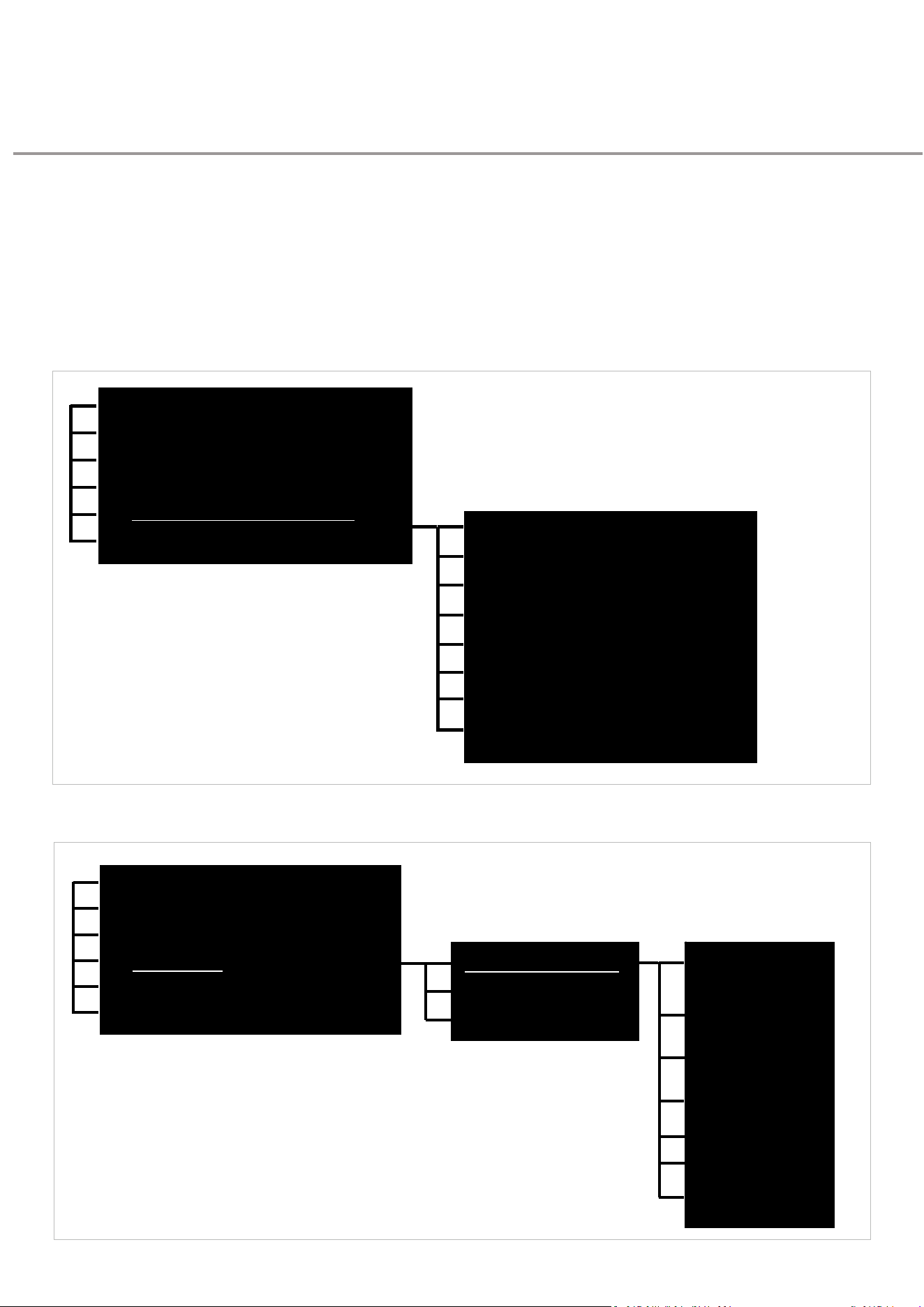
59
DAVECommercialDoorOperator—InstructionalManual
Resettingto Factory
Defaults
RESETOPTIONSOVERVIEW
Resetfunctionsfortheoperatorandwallconsoleareaccessedthroughthetwoseparate
menusshownbelow.
Fordescriptionsofeachfunction,refertothefulllistofDAVE’sprogrammingoptionsonpage
62.
MEMORYRESET&CONFIGUREMENUOPTIONS
1:
REMOTE CONTROL LEARN MENU
2
:
S
E
TT
I
N
G
S
A
N
D
M
O
D
E
A
D
J
U
S
TM
E
N
T
M
E
N
U
3
:
C
O
N
TR
O
L
&
S
A
F
E
T
Y
I
NPUT
ST
A
TU
S
M
E
N
U
4: CONSOLE MENU
5
:
M
E
M
O
R
Y
R
E
S
E
T
&
C
O
N
F
I
G
U
R
E
M
E
N
U
>
C
L
E
A
R
TR
A
VE
L
L
I
M
I
T
M
E
M
O
R
Y
6
:
I
N
F
O
M
E
N
U
R
EP
R
O
F
I
LE
D
OO
R
TR
A
V
EL
S
A
VE
P
O
S
I
T
I
O
N
F
O
R
P
A
RT
O
P
E
N
A
CC
E
SS
R
ES
C
A
N
F
O
R
A
CC
ES
S
O
R
Y
D
E
V
I
C
ES
RELOAD DEFAULT SETTING?
UNLEARN ALL REMOTES FROM MEMORY?
Thismenuprovidesaccesstomostreset
FACTORY RESET CONTROLLER?
f
un
c
ti
o
n
s
U
N
L
E
A
R
N
C
O
N
S
O
L
E
?
U
S
E
P
R
I
O
R
T
O
C
O
NN
E
C
T
I
N
G
N
E
W
C
O
N
S
O
L
E
CONSOLESETUP&RESET
1: REMOTE CONTROL LEARN MENU
2
:
S
E
TT
I
N
G
S
A
N
D
M
O
D
E
A
D
J
U
S
TM
E
N
T
M
E
N
U
3
:
C
O
N
TR
O
L
&
S
A
F
E
T
Y
I
NPUT
ST
A
TU
S
M
E
N
U
4
:
C
O
N
S
O
L
E
M
E
N
U
>
C
O
N
S
O
L
E
S
E
T
U
P
&
R
E
S
E
T
>
U
N
P
A
I
R
O
PER
A
T
O
R
5
:
M
E
M
O
R
Y
R
E
S
E
T
&
C
O
N
F
I
GU
R
E
M
E
N
U
CON
S
O
L
E
S
E
T
TI
N
G
S
F
RO
M
C
O
N
S
O
L
E
6
:
I
N
F
O
M
E
N
U
C
O
N
S
O
LE
I
N
FO
CONN
E
C
TI
O
N
M
O
D
E
AUTO DETECT
CONNECTION MODE
WIRED
CONNECTION MODE
T
hi
s
m
e
nu
p
r
o
v
i
d
e
s
a
cc
e
ss
t
o
W
I
R
ELE
SS
thefunctionforunpairingtheconsolefrom
TOOLBOX APP
theoperatorandguidanceonhowtounpair
theoperatorfromtheconsoleviaDAVE’s
CONSOLE FW UPDATE
controlboard
U
N
PA
I
R
C
O
N
S
O
L
E
FROM OPERATOR
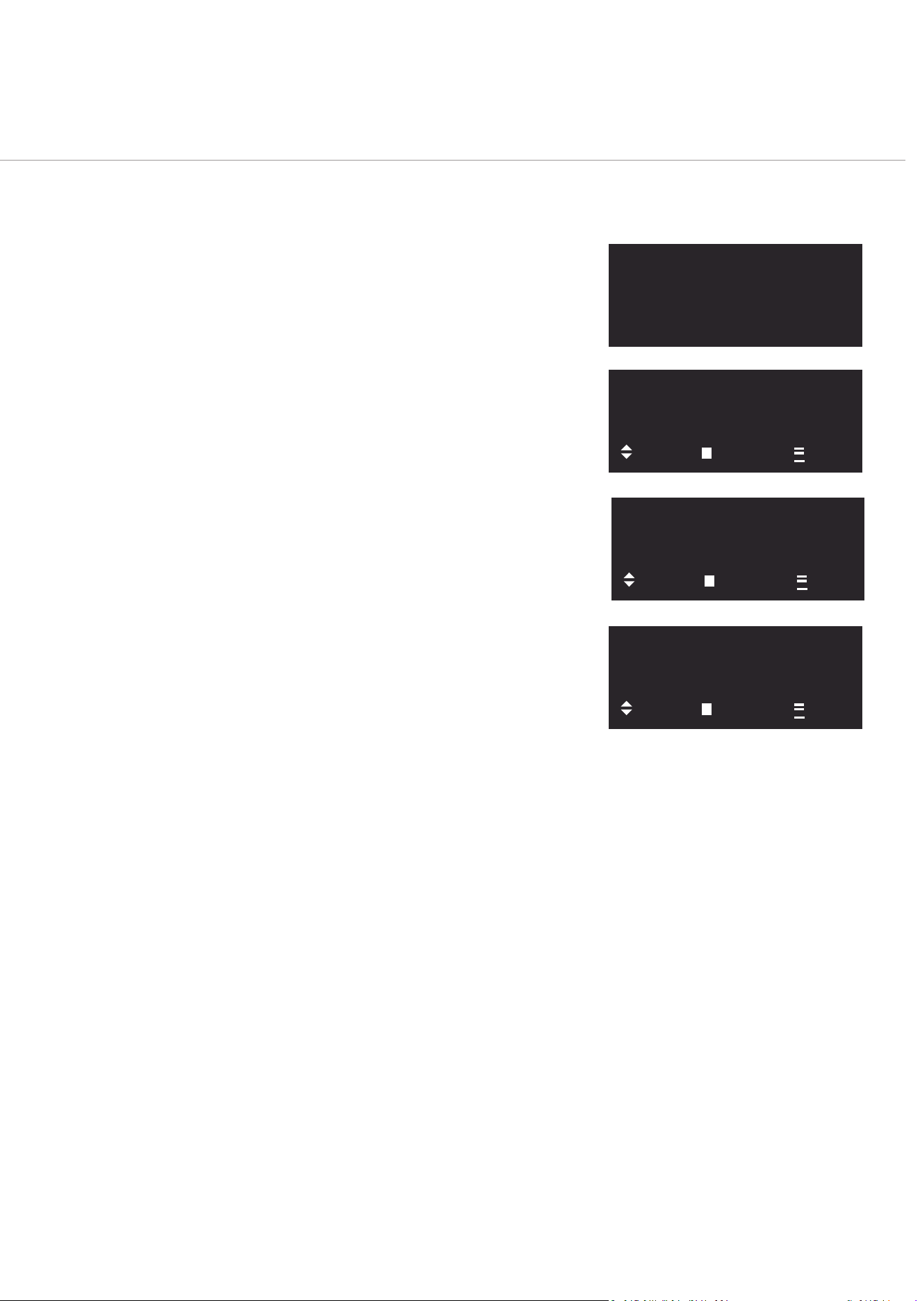
60
DAVECommercialDoorOperator—InstructionalManual
ACTIVATE KEY SWITCH
TO ACCESS LIMIT
SETUP & MENUS
ACCESSINGMEMORYRESETFUNCTIONS
1.
ActivatetheConsole
Iftheconsolescreenisoff,pressMENU(
).Ifitremainsoff,checkthepower
source.
2.
UnlocktheKeySwitch
Thekeyswitchmustbeunlockedtoproceed.Iflocked,theconsolewillpromptyou
(Fig:77).
3.
NavigatetoMemoryReset&ConfigureMenu
Press
repeatedlyuntilFig:78appears.Fromheretogglethroughthemenuusing
or
toreachFig:79.
4.
EnterMemoryResetMenuandChooseSettingto
Reset
AtFig:79press
.
Fig:80showsthefirstofthevariousresetfunctionsthatcanbe
accessedviathismenu.Fromheretogglethroughthemenuusing
or
tofind
therequiredresetfunction.
Descriptionsofeachfunctioncanbefoundunder5:MEMORYRESETAND
CONFIGUREMENUinthe“ProgrammingOptionsTable”onpage62.
Fig:77
Fig:78
Fig:79
Fig:80
1: REMOTE CONTROL
LEARN MENU
NEXT
START
EXIT
5:MEMORY RESET &
CONFIGURE
MENU
NEXT
START
EXIT
CLEAR TRAVEL LIMIT
MEMORY?
NEXT
YES
EXIT
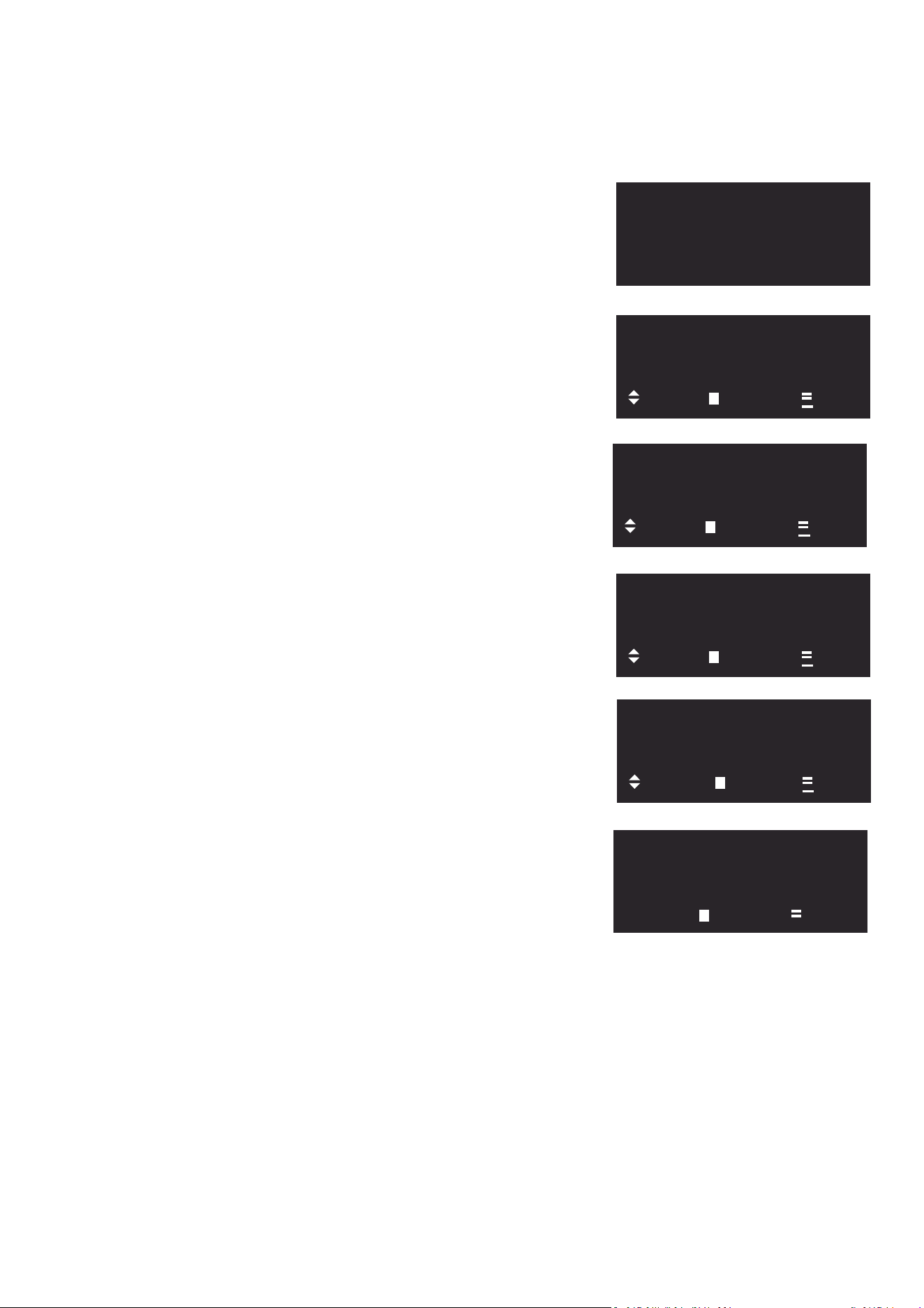
61
DAVECommercialDoorOperator—InstructionalManual
ACTIVATE KEY SWITCH
TO ACCESS LIMIT
SETUP & MENUS
UnpairConsoleFromOperator
1.
ActivatetheConsole
Iftheconsolescreenisoff,press
.Ifitremainsoff,checkthepower
source.
2.
UnlocktheKeySwitch
Thekeyswitchmustbeunlockedtoproceed.Iflocked,theconsole
willpromptyou(Fig:81).
3.
NavigatetoMemoryReset&Configure
Menu
Press
repeatedlyuntilFig:82appears.Fromheretogglethrough
themenuusing
or
toreachFig:83.
4.
NavigatetoConsoleSettings&Info
AtFig:83
toentertheConsoleSettingsandInfoMenu.Toggle
throughthemenuusing
or
toreachFig:84.
5.
NavigatetoUnpairConsoleOption
AtFig:84press
entertheConsoleSetup&Resetmenu.Toggle
throughthemenuusing
or
toreachFig:85.
6.
UnpairConsolefrom Operator
AtFig:85press
toinitiatetheunpairingprocess.Atthe
confirmationscreenFig:86press
onceagain.
Oncetheconsolehasdisconnected,itwillrestart.
Fig:81
Fig:82
Fig:83
Fig:84
Fig:85
Fig:86
1: REMOTE CONTROL
LEARN MENU
NEXT
START
EXIT
4:CONSOLE
SETTINGS
&
INFO
MENU
NEXT
ENTER
EXIT
CONSOLE SETUP &
RESET
NEXT
ENTER
EXIT
UNPAIR CONSOLE
FROM OPERATOR?
NEXT
EDIT
EXIT
WARNING: REMOVE
PAIRING TO OPERATOR
& SETUP AGAIN?
ENTER EXIT

62
DAVECommercialDoorOperator—InstructionalManual
ProgrammingOptionsTable
0.
NOTRAVELLIMITS SET
Forconfigu rationofopera toronfirstuse ,orafter
factoryreset.Usethismenutoselectdoortype
andselectlimits.
0.1.
SetupLimits
Setdoortypeandlimits.
0.1.1.
Select
door
type
Choosebetween
STANDARDSECTIONAL
VERTICAL/HIGHLIFT
ROLLINGSTEEL
CUSTOM
0.1.2.
Setcloselimit
Hold
or
todrive,or
tosave.
0.1.3.
Setopenlimit
0.2.
Doorwindupmode
Forshuttersonly.Usethismodeforwinding
shuttercurtainontodrumduringshutter
installation.
1.
REMOTECONTROL LEARNMENU
RemoteControlLearnMenu
1.1.
Learnremoteforopen/stop/close
LearnRemoteControlforNormalOperation.
CommandsequenceisOPEN/CLOSE/STOP
whenpressed.
1.2.
Learnremoteforopen
LearnRemoteControlforSpecialisedOperation.
CommandsequenceisOPENonlywhen
pressed.
1.3.
Learnremoteforstop
LearnRemoteControlforSpecialisedOperation.
CommandsequenceisSTOPonlywhenpressed.
1.4.
Learnremoteforclose
LearnRemoteControlforSpecialisedOperation.
CommandsequenceisCLOSEonlywhen
pressed.
1.5.
Learnremoteforpartialopen
LearnRemoteControlforSpecialisedOperation.
CommandsequenceiscontrolofPartialOpen
(SecondaryLimitposition)whenpressed.
1.6.
Learnremoteforcourtesylight
LearnRemoteControlforSpecialisedOperation.
Commandsequenceistocontrolalightwired
throughDAVE’sRelayExpansionBoard.
1.7.
Learnremoteforremotelockout
LearnRemoteControlforSpecialisedOperation.
CommandsequenceiscontrolofLockoutofall
storedremotecontrolswhenpressed.
1.8.
Learnremoteforauxiliaryoutput
LearnRemoteControlforSpecialisedOperation.
CommandsequenceiscontrolofAuxiliary
OutputfunctionwhenwiredthroughDAVE’s
RelayExpansionBoardtocontrolanotherdevice.

63
DAVECommercialDoorOperator—InstructionalManual
2.
SETTINGSANDMODEADJUSTMENTMENU
Settings&ModeAdjustmentMenu
2.1.
Auto‐closetime(sec)[0=off]
NoteAuto‐Closingfunctioncanonlybeinitiated
whenSafetyDevicesarecommissioned&
functioning.
StandardAuto‐Close(TimertoClose)
AutoCloseFunctionsfromfullyopenposition
alwaysaftertimercountdownexpires
Adjustablein
1
Secondincrements
Defaultisof
f
Min0SecondsMax255Seconds
2.2.
SDauto‐closetime(sec)[0=off]
NoteAuto‐Closingfunctioncanonlybeinitiated
whenPEBeamsarecommissioned&functioning
PETriggeredAuto‐Close(TimertoClose)
AutoCloseFunctionsonlyafteraninterruptiono
f
PhotoCells.Withoutthisinterruption,countdown
timerdoesnotcommence.
Adjustablein
1
Secondincrements
Defaultisof
f
Min0SecondsMax255Seconds
2.3.
C
o
u
r
t
e
s
y
L
i
g
h
t
t
i
m
e
r
(
s
e
c
)
1
8
0
AdjustableLightTimertoanyLightwiredto
product(Relaymoduleisrequired)
Adjustablein
1
secondincrements
Defaultis180Seconds
Min0SecondsMax255seconds
2.4.
AuxiliaryOutputtime(sec)
1
AdjustableAUXOUTPUT(Whenwiredthrough
DAVE’sRelayExpansionBoardtocontrolanother
device)
Adjustablein
1
secondincrements
Defaultis
1
Second
Min0SecondsMax255Seconds
2.5.
C
l
o
s
e
S
p
ee
d
R
P
M
1
5
00
AdjustableCLOSINGSPEEDscaledinRPM.
Adjustablein100RPMincrements.
Settingsdependontheselecteddoortype,
e.g.forRollingSteeldoors,DefaultOpening
Speed=1500,Min=700,Max=3000
2.6.
O
p
e
n
S
p
ee
d
R
P
M
1
7
00
AdjustableOPENINGSPEEDscaledinRPM.
Adjustablein100RPMincrements.
Settingsdependontheselecteddoortype,
e.g.forRollingSteeldoors,DefaultOpening
Speed=1700,Min=700,Max=3000
2.7.
SlowDownRate250
SOFTSTOPCONTROL.Adjustsrateatwhich
doorslowstoastop.Decreasethevaluefora
softerstop/moregradualdeceleration.Setto
maximumvalueforanimmediatestopwithno
deceleration.
2.8.
SpeedUpRate80
SOFTSTARTCONTROL.Adjustsrateatwhich
dooracceleratesfromstationarytoprogrammed
travelspeed.Decreasethevalueforsofterstart
/moregradualacceleration.Settomaximum
valuetostartopeningatprogrammedtravel
speed.
2.9.
SafetyDevice
1
type off
SafetyDeviceInputnumber
1
Menu
InputOffasdefault.
Optionneedstobeselectedifusinginput
2
.
9
.1
.
S
a
f
e
t
y
D
e
v
i
c
e
S
D
1
t
y
p
e
S
B
WiredSafetyDeviceSelectionOption
1
Safety
Beam(ATBrandPEBeams)
2.
9
.
2.
S
a
f
e
t
y
D
e
v
i
c
e
S
D
1
t
y
p
e
P
U
L
WiredSafetyDeviceSelectionOption2Pulse
Type(MillerEdgeSafetydevices)
2
.
9
.
3
.
S
a
f
e
t
y
D
e
v
i
c
e
S
D
1
t
y
p
e
1
0
K
WiredSafetyDeviceSelectionOption3:(10K)
OhmResistortype(MillerEdgeSafetyDevices)

64
DAVECommercialDoorOperator—InstructionalManual
2
.1
0
.
SafetyDevice2typeoff
SafetyDeviceInputnumber2Menu
InputOffasdefault.
Optionneedstobeselectedifusinginput
2
.1
0
.1
.
S
a
f
e
t
y
D
e
v
i
c
e
S
D
2
t
y
p
e
S
B
WiredSafetyDeviceSelectionOption
1
Safety
Beam(ATBrandPEBeams)
2.
1
0
.
2.
S
a
f
e
t
y
D
e
v
i
c
e
S
D
2
t
y
p
e
P
U
L
WiredSafetyDeviceSelectionOption2Pulse
Type(MillerEdgeSafetydevices)
2
.1
0
.
3
.
S
a
f
e
t
y
D
e
v
i
c
e
S
D
2
t
y
p
e
1
0
K
WiredSafetyDeviceSelectionOption310KOhm
Resistortype(MillerEdgeSafetyDevices)
2.11.
SafetyDevice3typeoff
SafetyDeviceInputnumber3Menu
InputOffasdefault.
Optionneedstobeselectedifusinginput
2.11.1.
SafetyDeviceSD3typeSB
WiredSafetyDeviceSelectionOption
1
Safety
Beam(ATBrandPEBeam)
2.11.2.
SafetyDeviceSD3PUL
WiredSafetyDeviceSelectionOption2Pulse
Type(MillerEdgeSafetydevices)
2
.1
1
.
3
.
S
a
f
e
t
y
D
e
v
i
c
e
S
D
3
t
y
p
e
1
0
K
WiredSafetyDeviceSelectionOption310KOhm
Resistortype(MillerEdgeSafetyDevices)
2.12.
I
g
n
o
r
e
S
D
1
f
o
r
F
i
r
e
&
P
a
r
t
C
l
o
s
e
=
N
o
Forfire&partclosecyclescustomercanchoose
toignoresignalsfromsafetydeviceSD1
2.13.
IgnoreSD2forFire&PartClose=No
Forfire&partclosecyclescustomercanchoose
toignoresignalsfromsafetydeviceSD2
2.14.
IgnoreSD3forFire&PartClose=No
Forfire&partclosecyclescustomercanchoose
toignoresignalsfromsafetydeviceSD3
2.15.
IgnoreWPE1forFire&PartClose=No
Forfire&partclosecyclescustomercanchoose
toignoresignalsfromsafetydeviceWPE1
2.16.
IgnoreWPE2forFire&PartClose=No
Forfire&partclosecyclescustomercanchoose
toignoresignalsfromsafetydeviceWPE2
2.17.
Relay
1
modelight
Relaynumber
1
ControlMenuModesDefaultis
LIGHTMode(WiredCourtesyLight)
2.17.1.
Relay
1
modeopen
Relayactivewhendoorisfullyopen
2.17.2.Relay
1
modeclosed
Relayactivewhendoorisfullyclosed
2.17.3.Relay
1
modepartopen
Relayactivewhendoorispartopen
2
.
1
7
.
4
.
R
e
l
a
y
1
m
o
d
e
pa
r
t
c
l
o
s
e
Relayactivewhendoorispartclosed
2.17.5.Relay
1
mode
smoke
baffle
Relayactivewhendoorisatsmokebaffle
position
2.17.6.Relay
1
modemovementwarn
1
HZFlashwhendoorismoving
2.17.7.Relay
1
modemovement
Relay
1
activewhiledoorismoving
2.17.8.Relay
1
modeunattended warn
Pre‐drivewarningwhenSmartPhoneisenabled
2.17.9.Relay
1
modeAUXoutput
AUXOUTPUTSpecializedcustomoutputfor
LightsSeeInstallationGuideformoredetails
2
.1
7
.1
0
.
R
e
l
a
y
1
m
o
d
e
a
l
e
r
t
s
t
a
t
u
s
Relayactivatesonlyintheeventofanalert
2.17.11.
Relay
1
modefault status
Relayactivatesintheeventoffault
2.17.12.Relay
1
modeoff
Relayisinactive(Disabled)
2.18.
Relay2modeopen
Relaynumber2ControlMenuModes

65
DAVECommercialDoorOperator—InstructionalManual
DefaultisOPENMode
Relayactivewhendoorisfullyopen
2.18.1.
Relay2 mode closed
Relayactivewhendoorisfullyclosed
2.18.2.
Relay2mode
part
open
Relayactivewhendoorispartopen
2.18.3.
Relay2mode
part
close
Relayactivewhendoorisatpartclose
2.18.4.
Relay2modesmoke baffle
R e l a y a c t i v e w h e n d o o r i s a t s m ok e b a f f l e
position.
2.18.5.
Relay2modemovementwarn
1
HZFlashwhendoorismoving
2.18.6.
Relay2 modemovement
R e lay2ac t i v e w h i ledooris m o v i n g
2.18.7.
Relay2modeunattendedwarn
Pre‐drivewarningwhenSmartPhoneisenabled
2.18.8.
Relay
2
mode AUX output
AUXOUTPUT
SpecialisedcustomoutputforLights.
2.18.9.
Relay2mode
alert
status
Relayactivatesonlyintheeventofalerts
2.18.10.
Relay2mode fault status
R e l a y a c t i v a t e s i n t h e e v e n t o f a f a u l t
2.18.11.
Relay2 mode off
Relayisinactive(Disabled)
2.18.12.
Relay2mode
light
Relayisactivelikealightswitch
2.19.
Relay3modeaux output
Relaynumber3ControlMenuModes
DefaultisAUXMode.
2.19.1.
Relay3mode
alert
status
Relayactivatesonlyintheeventofalerts
2.19.2.
Relay3modefault status
R e l a y a c t i v a t e s i n t h e e v e n t o f a f a u l t
2.19.3.
Relay3mode off
Relayisinactive(Disabled)
2.19.4.
Relay3 mode
light
Relayisactivelikealightswitch
2.19.5.
Relay3mode open
Relayactivewhendoorisfullyopen
2.19.6.
Relay3 mode closed
Relayactivewhendoorisfullyclosed
2.19.7.
Relay3mode
part
open
Relayactivewhendoorispartopen
2.19.8.
Relay3modepartclosed
Relayactivewhendoorispartclosed
2.19.9.
Relay3modesmoke baffle
R e l a y a c t i v e w h e n d o o r i s a t s m ok e b a f f l e
position
2.19.10.
Relay
3
modemovementwarn
1
HZFlashwhendoorismoving
2.19.11.
Relay3 mode movement
Relay3activewhiledoorismoving
2.19.12.
Relay3modeunattendedwarn
Pre‐drivewarningwhenSmartPhoneisenabled
2.20.
Relay4modemovement
Relaynumber4ControlMenuModes
DefaultisMOVEMENTWARNING
Relayonlyactivateswitha1HZFlashwhendoor
ismoving
2.20.1.
Relay4modeunattendedwarn
Pre‐drivewarningwhenSmartPhoneisenabled
2.20.2.
Relay4modeAUXoutput
SpecialisedcustomoutputforLightsSee
InstallationGuideformoredetails
2.20.3.
Relay4mode
alert
status
Relayactivatesonlyintheeventofalerts

66
DAVECommercialDoorOperator—InstructionalManual
2.20.4.
Relay3modefault status
R e l a y a c t i v a t e s i n t h e e v e n t o f a f a u l t
2.20.5.
Relay4modeoff
Relayisinactive(Disabled)
2.20.6.
Relay
4
mode light
Relayisactivelikealightswitch
2.20.7.
Relay4modeopen
Relayactivewhendoorisfullyopen
2.20.8.
Relay4modeclosed
Relayactivewhendoorisfullyclosed
2.20.9.
Relay
4
modepart open
Relayactivewhendoorispartopen
2.20.10.
Relay
4
mode part close
Relayactivewhendoorispartclosed
2.20.11.
Relay4modesmokebaffle
R e l a y a c t i v e w h e n d o o r i s a t s m ok e b a f f l e
position
2.20.12.
Relay
4
modemovementwarn
1 H z f l a s h w h e n d o o r i s m o v i n g
2.21.
GPAinputfunctionpart open
GeneralPurposeAccessoryInputMenu
DefaultisPARTIALOPENING(PEDESTRIAN)
WhenwiredtothisinputCommandreflects
PARTIALOPENINGsetting
2.21.1.
GPAinputfunctionpartclose
Whenthiswiredinputactiv ates,doorwillmoveto
partclosedposition
2.21.2.
GPAinputfunction swipe
Whenswipeinputactivates,thedoorwillopen
andremainpartlyopenuntilswipeinputis
deactivated
2.21.3.
GPA function off
GPAfunctionoff(Inactive)
2.22.
GPBinputfunctionswipe
Whenswipeinputactivates,thedoorwillopen
andstayopenuntilswipeinputisdeactivated
2.23.
GPBinputfunction
fire:
openor close
ActivationofGPBwillcausethedoortoopenor
closetothesmokebaffleposition
2.24.
GPBinputfunction
fire:
close only
ActivationofGPBwillcausethedoortoonly
closetosmokebaffleposition.
2.25.
GPB
inputfunctionfirealarmopen or
close
N o r m a l l y c l o s e d c o n t a c t w i t h 1 0 k r e s i s t o r a c r o s s
contactisusedforthisfunction.Whenactivated
doorwillopenorclosetosmokebaffleposition.
2.26.
GPB
inputfunctionfirealarmnot
closed
N o r m a l l y c l o s e d c o n t a c t w i t h 1 0 k r e s i s t o r a c r o s s
contactisusedforthisfunction.Whenactivated
doorwillonlyclosetosmokebaffleposition.
2.27.
GPBinput function off
GPBisdeactivated
2.28.
Preclose warningoff
PreDriveCLOSEWARNINGwhenDAVE’Srelay
expansionboardisused.
MenuDefaultisOFF
2.28.1.
Preclose warningon
Pre‐driveCLOSEWARNINGwhenDAVE’Srelay
expansionboardisused:Thisfeaturecanbe
usedfora“keepcleardoorisabouttoclose”
warning.
2.29.
Maintenance cycle preset
ServiceAlertinCycles(Preset)
PreloadedServiceAlertinquantityofcycles
Adjustablein
1
Cycleincrements
Defaultis0(disabled)
Minimumis0CyclesMaximumis65535Cycles

67
DAVECommercialDoorOperator—InstructionalManual
3.
CONTROLANDSAFETYINPUTSTATUS MENU
DiagnosticsMenuforControl&SafetyInputs
3.1.
Controlinputstatus
Diagnosticfeedrelatingtowiredinputs
LEGEND‐TextisLowerCase=inputOK
LEGEND‐TextisUPPERCASE=Inputfault
recognized
GuidetoInputabbreviations
stp=Stop
opn=Open
cls=Close
osc=OpenStopClose
gpa=GeneralPurposeinputA
gpb=GeneralPurposeinputB
int=interlockinput
ten=cabletensioninput
man=manualoperation
3.2.
Safetydevicesstatus
StatusofSafetyDevicemenu
ReportsonActiveorInactiveON/OFFprompt
ReportsonSafetyDeviceinputs
LegendforInputAbbreviations
SD1=SafetyDeviceinput
1
SD2=SafetyDeviceinput2
SD3=SafetyDeviceinput3
4.
CONSOLEMENU
4.1.
Consolesettings
ConsoleSettingsmenu
4.1.1.
Wakemodesleep
ConsoleBatteryPowerSavingModeSettings
DefaultsettingisWAKEMODESLEEP(See
manualforexpandedview)
4.1.1.1.
Sleep[powersaver]
WAKEONMENUPRESSSLEEPMODE.The
highestPowersavingmode.Consolewakesup
onlywhenmenubuttonispressed
4.1.1.2.
Notify[highpower]wakeonanychange
NOTIFY.Thehighestpowerconsumptionmode.
Consolewakesuponanychangeoractionto
console
4.1.1.3.
Interact[balanced]wakeonconsoleuse
INTERACTThebalancedpowerconsumption
modeConsolewakesuponlywhenconsoleis
used
4.1.2.
Screentimeout (secs)20
TimeOutPerioduntilLCDturnsoff
Adjustablein
1
Secondincrements
Defaultis20Seconds
Minimum5SecondsMaximum120Seconds
4.1.3.
Screencontrast40
Contrast(Brightness)ofLCD
Adjustablein
1
contrastratiounitincrements
Defaultis40units
Minimum
1
unit‐Maximum100units

68
DAVECommercialDoorOperator—InstructionalManual
4.2.
Console
info
ConsoleInformationMenu
4.2.1.
PowermodebatteryOK
StatusCh eckBa tteryPow erMod eCheck&Test
4.2.2.
Connectionstatewireless
StatusCheckofconnectionofconsoletoDrive
UnitWiredorWireless
4.2.3.
ConsoleVersion
x.x.x
VersionofConsolefirmware
4.2.4.
CommsVersionx.x.x
Communicationsprotocolversion
4.3.
Consolesetup and reset
ConsoleSetUp&ResetMenu
4.3.1.
Unpairoperatorfrom console
ClearandresetConsolewithfactoryresetback
tooutofboxcondition.
Alltheincludinglimits,doortypeandspeedare
retainedbytheoperator.
Notethisoperationdoesnotfullybreakthe
bondingbetweentheoperatorandConsole.The
operatorwillstillretaintheConsole’suniqueID
inmemoryandcanonlybere‐pairedwiththis
Console.
ToremovetheConsole’suniqueIDfromthe
operator’smemory,seeitem4.3.6Unpair
ConsolefromOperator.
4.3.2.
Connectionmodewireless
PromptthatinwiredConsoleoptionModeisAuto
Detected&Set(Seemanualforexpandedview)
4.3.3.
ToolboxApp
ToolboxappwillbeusedtoupdateDAVE’s
firmwareviatoolboxphoneapp
4.3.4.
ConsoleFWUpdate
PhoneappcanbeusedtoupdateConsole
firmware
4.3.5.
CommsFWUpdate
PhoneappwillbeusedtoupdateDAVE’s
communicationsfirmware
4.3.6.
Unpairconsolefrom operator
ClearandresetBluetoothBond(Sync)between
ConsoleandDriveUnit.
ProvidesinstructionsforremovingtheConsole’s
uniqueIDfromtheoperator’smemoryviathe
controlboard.Thisstepisnecessaryifreplacing
theconsoleforanyreason.

69
DAVECommercialDoorOperator—InstructionalManual
5.
MEMORYRESET&CONFIGURE MENU MEMORYRESETSMENU
5.1.
Cleartravel
limit
memory
ClearallTravelLimitsmemory.Awaitsnewlimit
setupproceduretobecompleted
5.2.
Reprofiledoortravel
ReprofileFunction.
Clearsallforcecharacteristicsinmemoryand
recalibratesnewdoorrequirements
Operates3automaticoperationstocomplete
thisreprofiling
5.3.
Save
positionforpart open
access
Set
upoflimitpositionfor
PARTOPEN
(PedestrianAccess)
5.4.
Save
positionforpartclose
access
Setup/savelimitpositionforpartcloseaccess
5.5.
Save
positionfor
smoke
baffle
access
S e t u p / s a v e l i m i t p o s i t i o n f o r s m o k e b a f f l e
access
5.6.
Rescanfor accessory devices?
Rescanfunction
Electronicclearandre‐syncofwirelessdevices
Usedwhenconnectingandreconnectionof
wirelessbasestations
5.7.
Reload
default
settings?
ReloadDefaultSettingsinpowerdrivememory
5.8.
Unlearnallremotesfrommemory
ClearReceiverMemory
Eraseallstoredremotecontrolsfromreceiver
memorylocations
5.9.
Factory reset controller?
Thiswillcauseallcontrolmemorytoberesetto
factorydefaults,Excludingremotes,historylog
andlifetimecyclecounter
5.10.
Unlearn
Console?
Usepriortoconnectingnewconsole.
DisablesRFcommunicationsfromconsole,
i
.
e
.
U
p
(
)
D
ow
n
(
)
&
S
t
o
p
(
)
.
Allsettingsretainedonconsoleandoperator.
6. INFORMATIONMENU
InformationMenuDetailsofDriveUnitbuild
characteristicsdiagnosticsandoperational
history
6.1.
Modelnovus
1V1
VersionofMainPCB
6.2.
FirmwarefwVersion#
VersionofMainPCBfirmware
6.3.
Build
(MMM
DDYYYY)
BuilddateofFirmware
6.4.
Opencycles
OperationalhistoryOpenCyclesinunits
6.5.
Closecycles
OperationalhistoryCloseCyclesinunits
6.6.
Maintenanceduein (cycles)
CycleCountdowntoNextService
Displayshowmanycyclesremainuntilthenext
service.
0=ServiceNowDue
LinkedtoMaintenanceCyclepreset.
Disabledbydefault
Toenable:
1)Loadthemaintenancecyclepreset
2)Enterthenumberofcyclesbeforeserviceis
due.
6.7.
Lifetimecycles
OperationalLifecyclesinunits
Thisfigurecannotbeedited
6.8.
Openstalls
DiagnosticsOpenStall.
Astallcanbedetectedifthedooris
jammed

70
DAVECommercialDoorOperator—InstructionalManual
6.9.
Close stalls
DiagnosticsCloseStall
AstallcanbedetectediftheDooris
Jammed
6.10.
Direction faults
DiagnosticsDirectionFault
CreationofLimitpositioningissues
IssuedetectedatSureTrack™positioning
encoderorHarnesstoSureTrack™positioning
encoder
6.11.
Position faults
DiagnosticspositionfaultCreationofLimit
positioningissuesIssuedetectedatSureTrack™
positioningencoderorHarnesstoSureTrack™
positioningencoder
6.12.
Balance alert trips
Thiscounterindicateshowmanytimesbalance
alerttripwastriggered.Balancealerttripswhen
VBUSexceeds440voltsfor
1
second
6.13.
Balance alert cycles
Numberofcyclescompletedafterbalancealert
wastriggeredwithoutresetting
6.14.
Balance warning trips
Thiscounterindicateshowmanytimesbalance
warningtripswastriggered.Balancewarning
tripswhenVBUSexceeds460voltsfor
1
second
6.15.
Balance warning cycles
Numberofcyclescompletedafterbalance
warningwastriggered
6.16.
Open position count
Limitassemblycounterwhichcontroltravel
distanceofthedoor
6.17.
Closetraveltime
Showsthetimeinsecondsforthedoortotravel
betweenitsopenandcloselimits
6.18.
Open travel time
Showsthetimeinsecondsforthedoortotravel
betweenitscloseandopenlimits
6.19.
Event history
Fulleventlogoflast90events.

71
DAVECommercialDoorOperator—InstructionalManual
8.
SAFETYDEVICESANDOTHER
CONTROLINPUTS
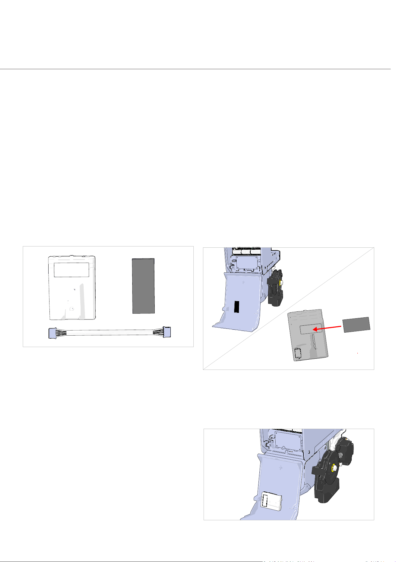
72
DAVECommercialDoorOperator—InstructionalManual
SafetyDeviceSetup
Tomeetinternationalsafetystandards,DAVEmusthaveaworkingsafetydevicduring
normaloperation.Ifnosafetydeviceisconnected,DAVEswitchestoDead‐Man(Constant‐
Contact)mode.
AsaWireless‐Firstdevice,DAVEsupportsbothwirelessandwiredsafetydevices.
ConnectingWirelessSafetyBeams
Followthesestepstoinstallthebasestationunitused
withallAutomaticTechnologywirelesssafetybeams.
Refertothesafetybeaminstructionmanualforcomplete
instructionsonhowtoinstallandconfigurethesafety
beamkit.
1.
Pre‐requisites(Fig:87
)
Use the supplied self‐adhesive hook‐and loop strip and 4 pin
harness. Both items are included in the accessories envelope
forPartNo.101510andthesafetybeamkitforPartNo.101511.
2.
OpenControlBoardAccess Cover
RefertoRemovingMainControlBoardAccessCoveron
page37.
3.
AffixSelf‐AdhesiveHook‐and‐Loop
Strips(Fig:88)
Separatethehook‐and‐loopstrips.
Stickonepiecetothebasestationandtheothertotheinside
ofthecontrolboardaccessdoor.
4.
AttachBaseStationtoInsideofMain
ControlBoardAccessDoor(Fig:89)
Align the hook and loop strips to ensure a good grip and
attach the base station to the access door.
Fig:88
Fig:87
Fig:89
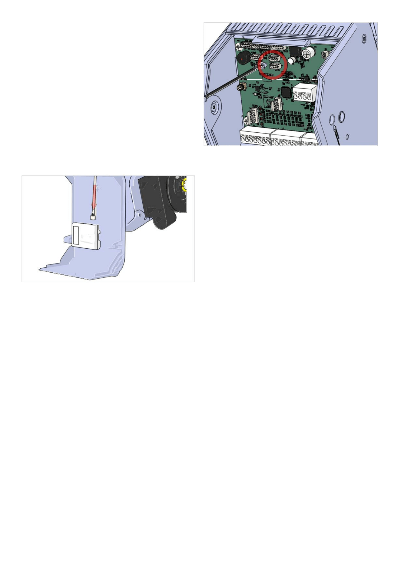
73
DAVECommercialDoorOperator—InstructionalManual
5.
ConnectHarness
Connectoneendoftheharnesstothebasestation
(Fig:90)andtheotherendtoeitherofthe2portsmarked
ACCESSORIESonthemaincontrolboard(Fig:91)
Fig:91
6.
ReplacetheControlBoardAccessDoor
(Fig:86)
ReplacethedoorbyfollowingthestepsshowninRemoving
MainControlBoardAccessCoveronpage37in
reverseorder.
Reinsertthescrewstosecureit.
Fig:90
7.
AutomaticDetection
DAVEwillautomaticallydetectthewirelessbasestation.
Noextrasetupisneededunlessyou’rereplacingawiredor
faultysafetybeamseeRescanForAccessoryDevices(point
5.6
onpage69intheProgrammingOptionsTable).
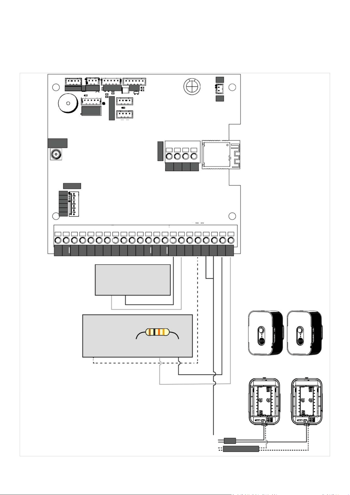
74
DAVECommercialDoorOperator—InstructionalManual
WiredSafetyDeviceWiringDiagrams
AUTOMATICTECHNOLOGYSAFETYDEVICES
POSITION
HUB
0V
24V
REMOTE
ANTENNA
B
A
0V 5V
24V
1
2
3
4
0V
RELAYS
CurrentPulseSafety
Mode:PUL
ExamplewirestoSD3
Pulsing=SystemOK
NoPulse=SystemnotOK
DryContact
SafetyMode:10K
ExamplewirestoSD2
Safety Device
V+ | GND
Safety Device
10KO Resistor
N/C | N/O | COM | V+ | GND
AutomaticTechnology
SafetyBeams
SafetyMode:SB
ExamplewirestoSD1
TRANSMITTER RECEIVER
NOTES
•
Wiringis for systems whereN/Cis active whenunbroken (System
OK).IfsystemisN/OwhenunbrokenthenSDreturnwireneedsto
befittedtoN/O
•
Somebrandsofsafetydeviceshavetheresistoralreadyfitted
internally.
•
OnsomesystemsCOMandGNDsharethesameinput.Inthiscase
youmayneedtowiretheresistorinlineonthesafetydevicesendto
theN/CorN/Odependingontheabove.
0V
WHITE
SB
WHITE
+ GREY
STRIPE
HOMELINK
RECEIVER
C
ONSOLE
24V
OV
SD1
OV
SD2
OV
SD3
OV
TEN
OV
INT
0V
GPB
0V
G
PA
OV
OSC
OV
CLS
OPN
STP
0V
A
C
CESSORIES
MTR COM
CHAIN
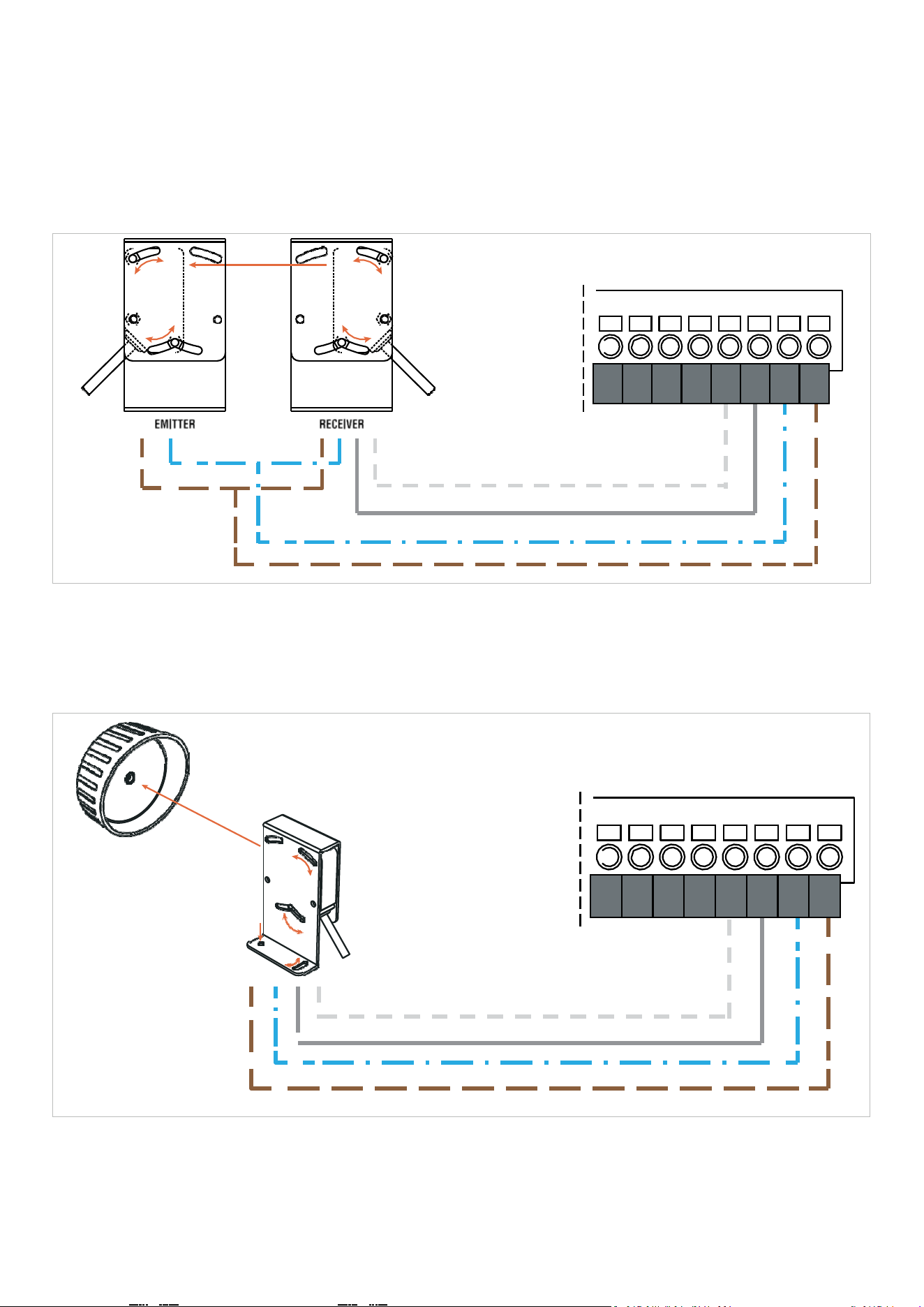
75
DAVECommercialDoorOperator—InstructionalManual
MILLEREDGESAFETYDEVICES
RECEIVER&TRANSMITTER BEAMS
24V
OV
SD1
OV
SD2
OV
SD3
OV
OG‐R‐K10
OptiGuard®
Monitored10K
SetSDModeto10K
REFLECTORBEAM
24V
OV
SD1
OV
SD2
OV
SD3
OV
TG‐R‐K10
TruGuard®Reflective
SetSDModeto10K
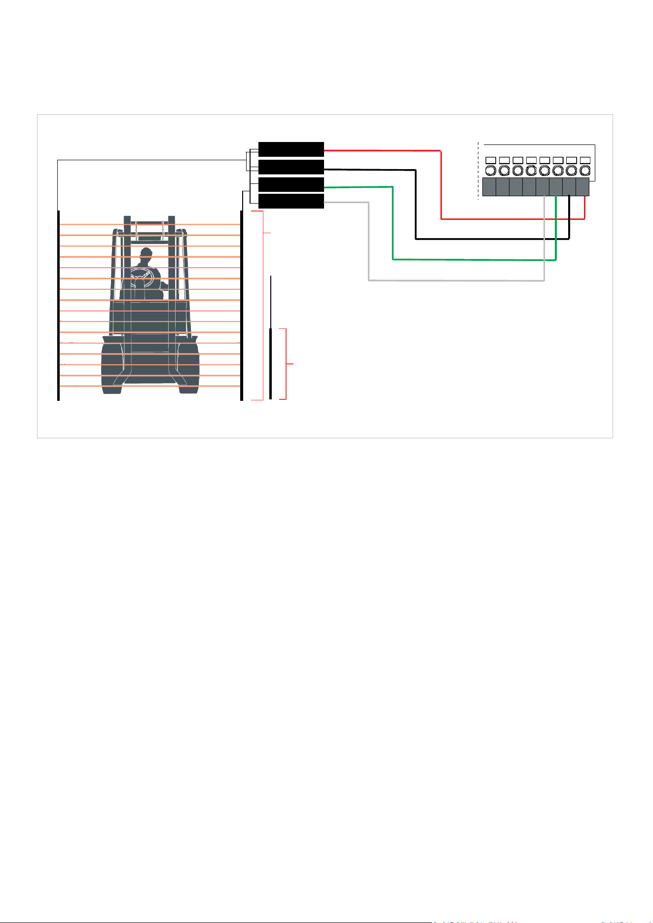
76
DAVECommercialDoorOperator—InstructionalManual
LIGHTCURTAINS
SETSDMODETOPUL
RED:12‐24VDC+
DAVE
BLACK:12‐24VDC‐
GREEN:PHOTOEYE
WHITE:PHOTOEYE
MLC‐K72
6 ft. (1.8 m)
16 elements
MLC‐K36
3 ft. (0.9 m)
8 elements
EMITTER
RECEIVER
24V
OV
SD1
OV
SD2
OV
SD3
OV
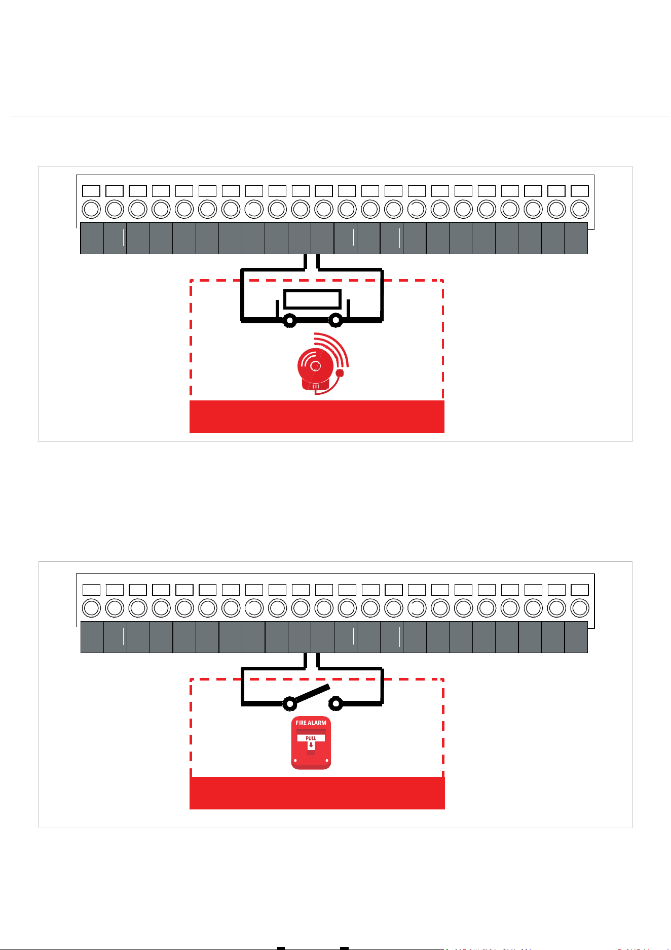
77
DAVECommercialDoorOperator—InstructionalManual
FireSystemInput
StandardFireAlarm Configuration
N
O
R
M
A
LL
Y
C
L
O
S
E
D
S
W
I
T
C
H
A
N
D
1
0
K
Ω
B
L
EE
D
E
R
R
E
S
I
ST
O
R
Doormovestosmokebafflepositionwhenalarmisactivated
StandardFireAlarmSwitch Configuration
ACTUATORSWITCHNORMALLYOPEN
Doormovestosmokebafflepositionwhenswitchisactivated
10KΩ
FIRE ALARM
FIRE ALARM SWITCH
24V
OV
SD1
OV
SD2
OV
SD3
OV
TEN
OV
INT
0V
GPB
0V
G
PA
OV
OSC
OV
CLS
OPN
STP
24V
OV
SD1
OV
SD2
OV
SD3
OV
TEN
OV
INT
0V
GPB
0V
G
PA
OV
OSC
OV
CLS
OPN
STP

78
DAVECommercialDoorOperator—InstructionalManual
FireInput&FunctionOverview
Thefollowingoutlinesthekeyfire‐relatedinputfunctionssupportedbyDAVE.Each
functionistriggeredviaGPAorGPBinput,andlinkstospecificdoorbehaviours.Forsetup
details,refertoProgrammingOptionsTableonpage62
FIREALARM–NOTCLOSE
MovesthedoortotheSmokeBafflePositiononlyifitisnotalreadyclosed.
Whenreleased,thedoorwillopenifabovethesmokebaffle.
TriggeredviaGPBinputwith10Kresistor.
Setthepositionusing:
→
5.5*Savepositionforsmokebaffleaccess
Safetydevicebehaviourisconfiguredin:
→2.10–2.14*IgnoreSDx/WPEforFire&PartClose
FIREALARM
DrivesthedoortotheSmokeBafflePosition,regardlessofcurrentposition.
Whenreleased,thedoorwillopen.
TriggeredviaGPBinputwith10Kresistor.
Referto:
→2.23*GPBinputfunconfirealarmopenorclose
→5.5*Saveposionforsmokebaffleaccess
FIRECLOSE
ClosesthedoortotheSmokeBafflePositiononly.
Ifalreadyatthatposition,inputisignored.
TriggeredviaGPBinput.
Referto:
→2.22*GPBinputfunconfire:closeonly
→5.5*Saveposionforsmokebaffleaccess
FIRE
OpensorclosesthedoortotheSmokeBafflePosition.
Ifalreadyatthatposition,inputisignored.
TriggeredviaGPBinput.
Referto:
→2.21*GPBinputfunconfire:openorclose
→5.5*Saveposionforsmokebaffleaccess
*SeeProgrammingOptionsTableonpage62
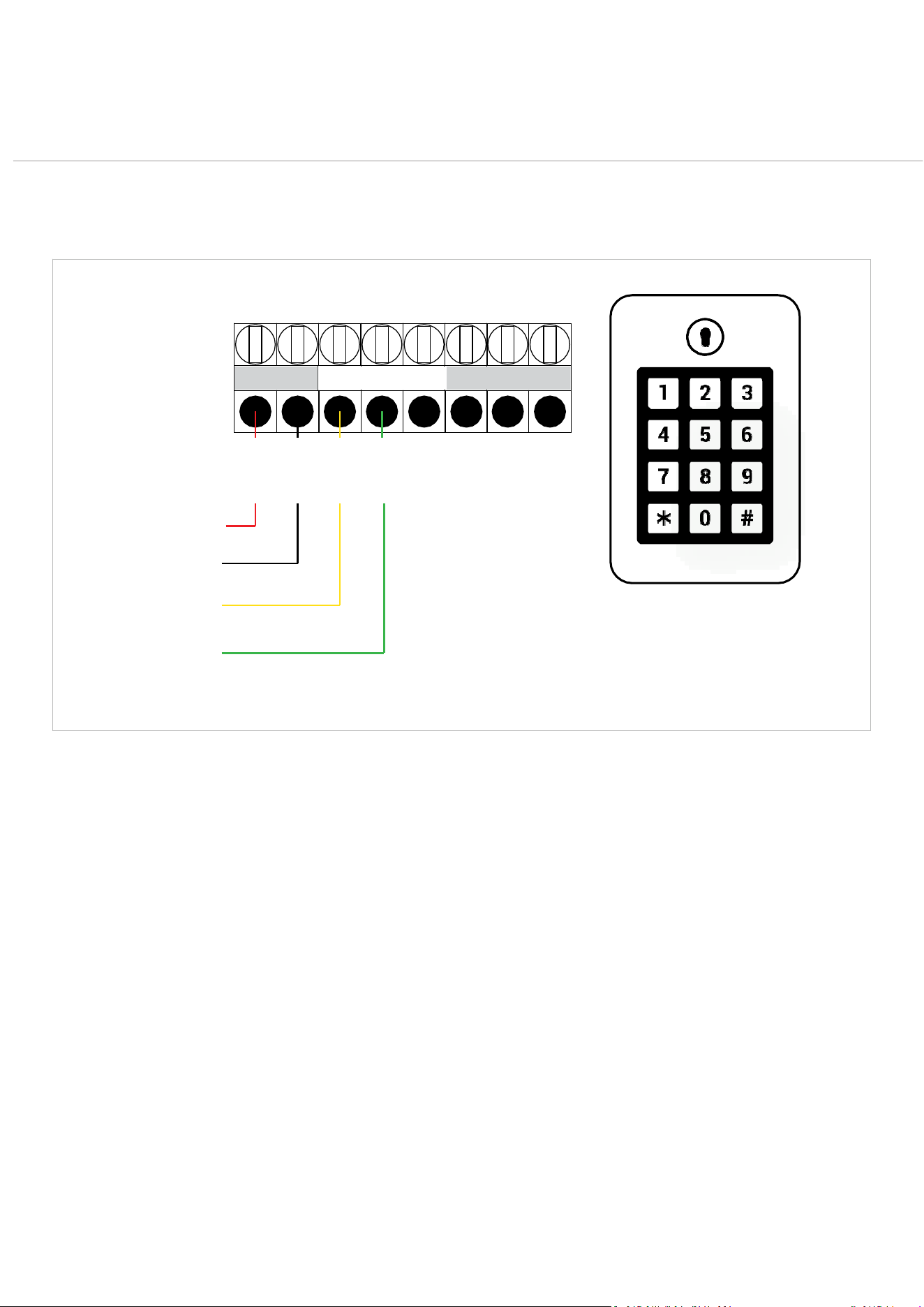
79
DAVECommercialDoorOperator—InstructionalManual
AccessDevices
Keypads
TYPICALKEYPADWIRINGCONFIGURATION.
Keypadrelayoutputsvaryfromonemodeltoanother.Pleaseconsultyourkeypadmanualfor
guidanceonwiringandhowtosetupaccesscodes.
12‐24VAC/DC
POWER
RELAYA
RELAYB
V24frommain
controlboard
0Vfrommain
controlboard
GPB
Defaultmode:SWIPE
0vfrommain
controlboard
OrcanbeLooped
to(‐)atKeypad
POS.(+)
NEG
.(-)
N/O
COM
N/C
N/O
COM
N/C
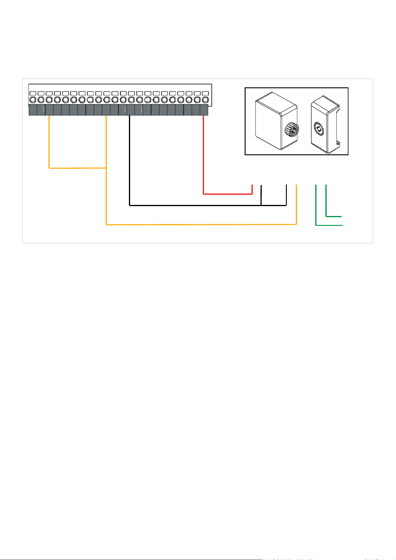
80
DAVECommercialDoorOperator—InstructionalManual
LoopDetectors
Loopdetectorsoftenemployarelayoutput.Thiswiringdiagramshowsatypical
configurationforaloopdetectorwitharelayoutput.
Makesuretoconsulttheinstructionmanualforyourloopdeviceforspecific
configurationdetails.
WiringOptions
•
ConnecttoeithertheGPBorGPAinputandsetwhicheverinputyouchooseto
“Swipe”mode.
•
ThedefaultsettingforGPBis“Swipe”mode.
•
IfneitherGPBnorGPAisavailable,theOPNinputcanalsobe used.
V+forLoop
Detector
DCInput
OutputRelay
COMN/O
LoopI/O
0VforLoopDetectorandRelayCommon
NO(NormallyOpen)RelayoutputfromLoopModule
ToLoop
24V
OV
SD1
OV
SD2
OV
SD3
OV
TEN
OV
INT
0V
GPB
0V
G
PA
OV
OSC
OV
CLS
OPN
STP
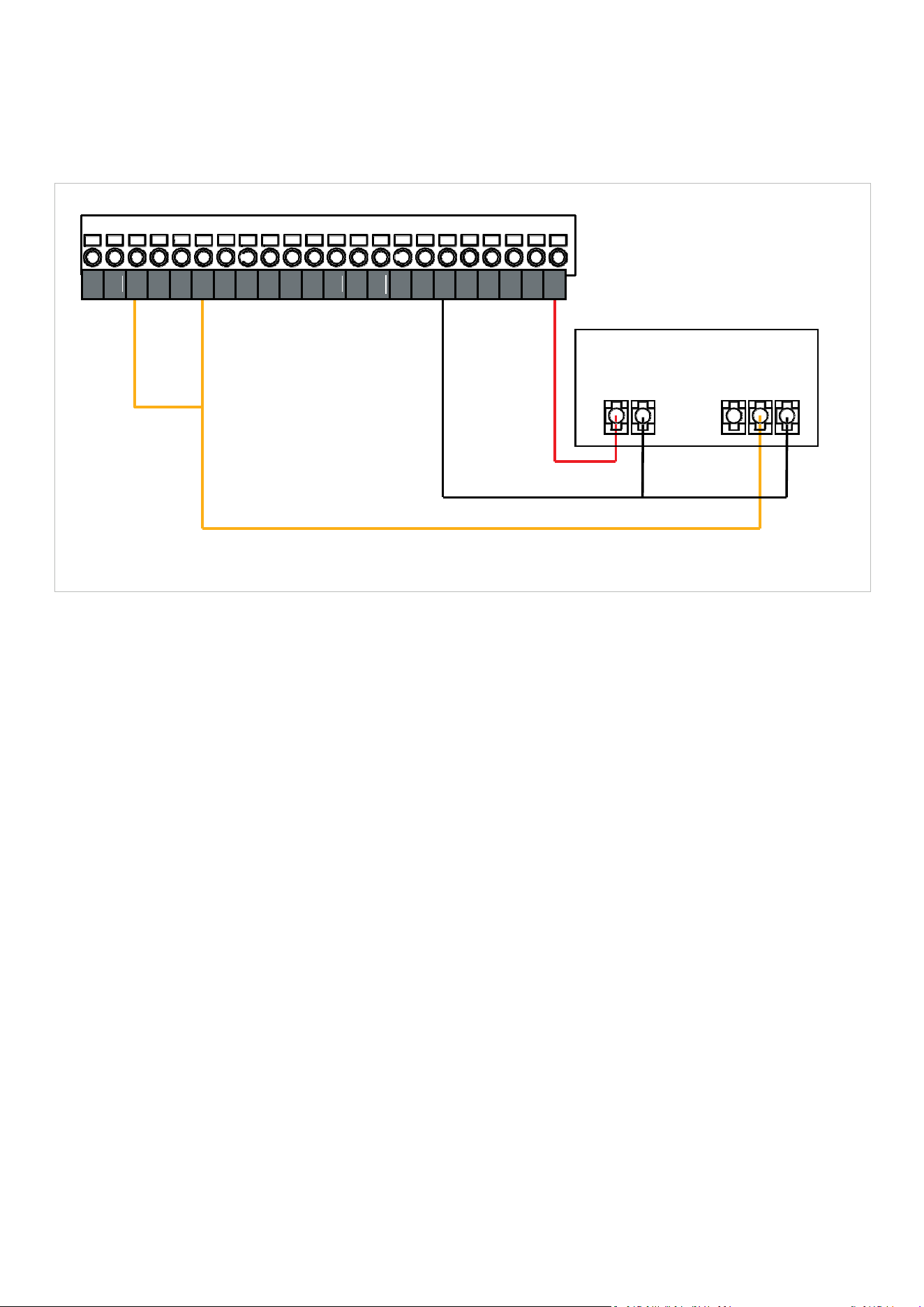
81
DAVECommercialDoorOperator—InstructionalManual
ExternalReceivers
Useanexternalreceiverifyouneedtointerfacewith3rdpartyremotecontrols,
orneedmoreremotesthanDAVE’sonboard63remotememorycapacity.
WiringdiagramforATFHCRXSingleChannelExternalReceiver
Relaysthatemployapull‐downoutputratherthanrelaydonotrequireaRelay
Common/COMconnection.
DAVEonlysupportsdevicesthatrunoffa24VDCpowersupply.Devices
requiringavoltageotherthan24Vmustbeconnectedtoanexternalpower
supply.
Beforeconnectinganexternalreceiverpleaseensureitsrelay/pull‐down
outputsaresuitedto5Vsignals.
0VforReceiver
andRelay Common
V+forReceiver
NO(NormallyOpen)RelayorPull‐DownoutputfromReceiver
24V
OV
SD1
OV
SD2
OV
SD3
OV
TEN
OV
INT
0V
GPB
0V
G
PA
OV
OSC
OV
CLS
OPN
STP

82
DAVECommercialDoorOperator—InstructionalManual
9.
DAVE’SRELAYEXPANSION
BOARD
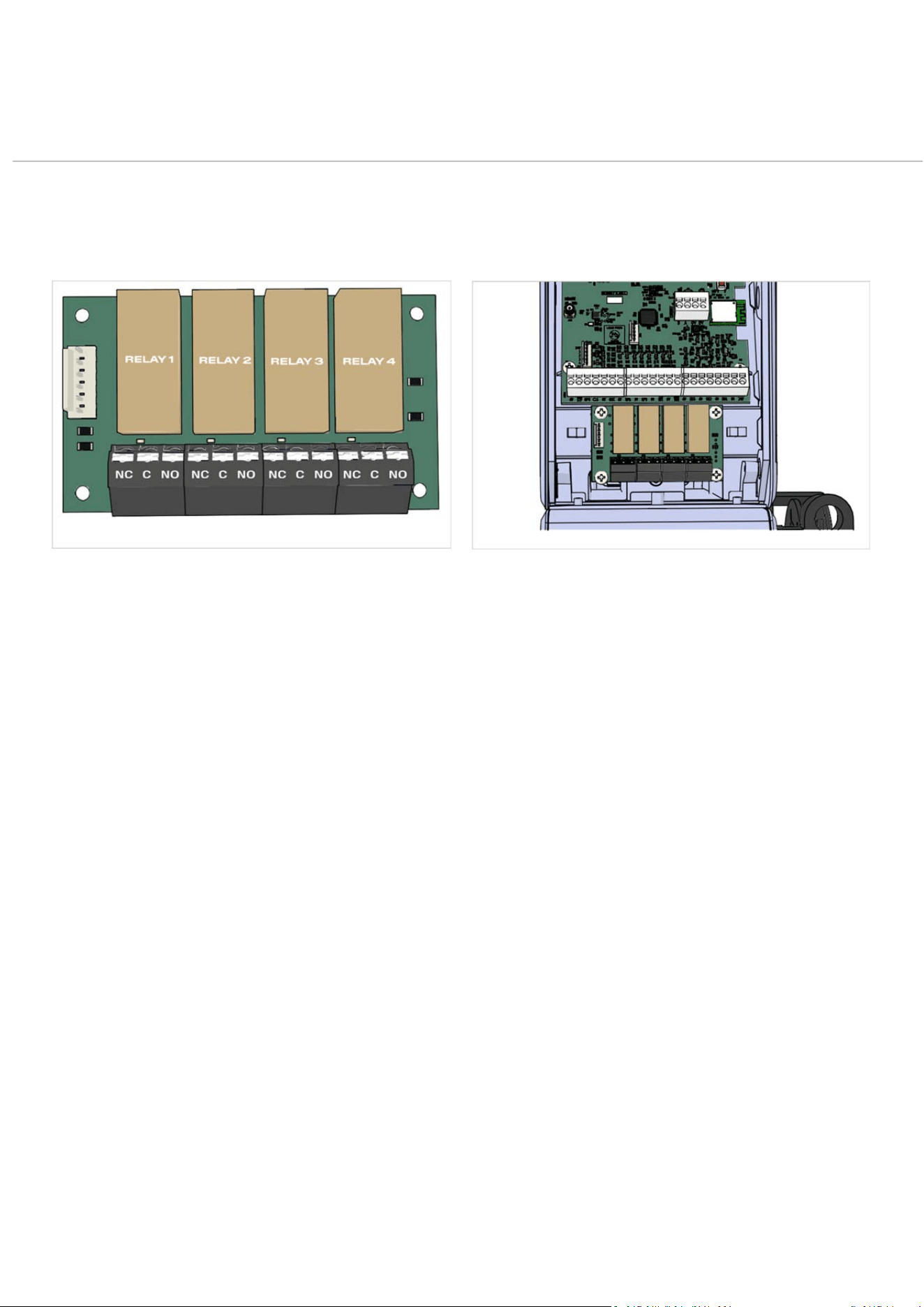
83
DAVECommercialDoorOperator—InstructionalManual
RelayExpansionBoard
Overview
DAVE’sRelayExpansionBoard(partno101960,soldseparately)provides4relay
modulesforcontrollingexternaldevices.Eachrelaymodulecanbeprogrammed
separatelyviatheWallConsole.AnydevicerequiringastatusoutputfromDAVEcanbe
operatedviaadrycontact
FEATURES
DAVE’sRelayExpansionBoardcomprises4programmable
relays,eachwith3drycontactsasshown.
•
NormallyOpen‐NO
•
Common‐C
•
NormallyClosed‐NC
Theboardsupportscontrolofdevicesoperatingon12V‐
24VDCorupto240VAC.
APPLICATIONS
•
Trafficlights
•
Flashingwarninglights
•
Sirens
•
Firealarmsystemoutputs
•
Accesscontrolsystems(outputs)
•
Emergencystopbuttons
•
Door interlocks
PROGRAMMING
PleaserefertoProgrammingOptionTable,points2.17‐2.20
onpage65.
INSTALLATION
PleaserefertotheinstructionmanualsuppliedwiththeRelay
ExpansionBoardkit.
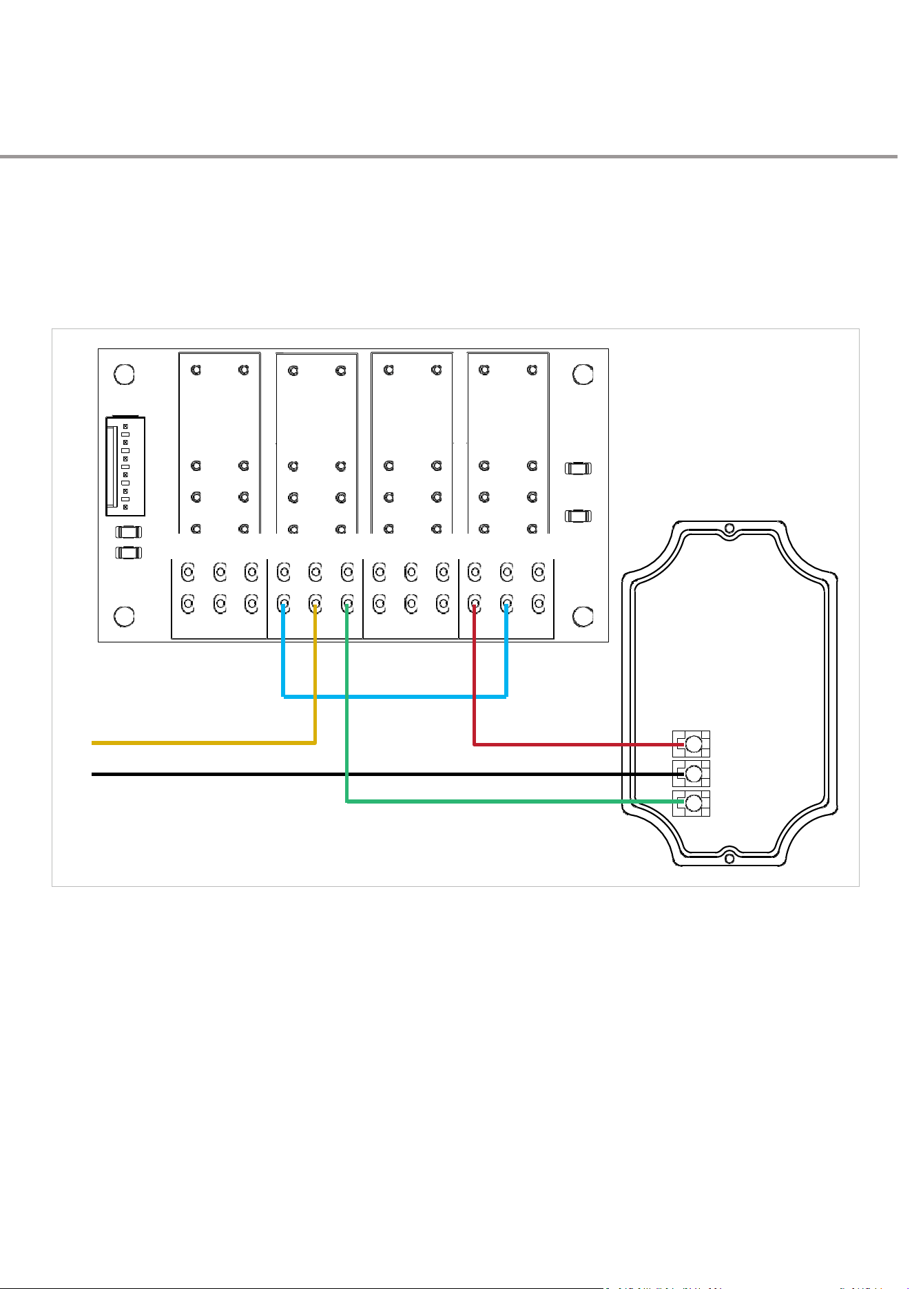
84
DAVECommercialDoorOperator—InstructionalManual
RelayBoardWiring
Examples
Trafficlights
LightOperationBasedonShownCircuit
•
RedLightisactiveifoperatorISNOTfullyopen
•
RedLightisflashingwhenoperatorisdriving
•
GreenLightisonwhendoorisfullyopen.
NC C NO NC C NO NC C NO NC
C
NO
T
RAFFIC
LIGHT
(+)externalPowerSupply
(‐)externalPowerSupply
R
ED
COM
GREEN
RELA
Y
1
RELA
Y
2
RELA
Y
3
RELA
Y
4
MO
VEMENT
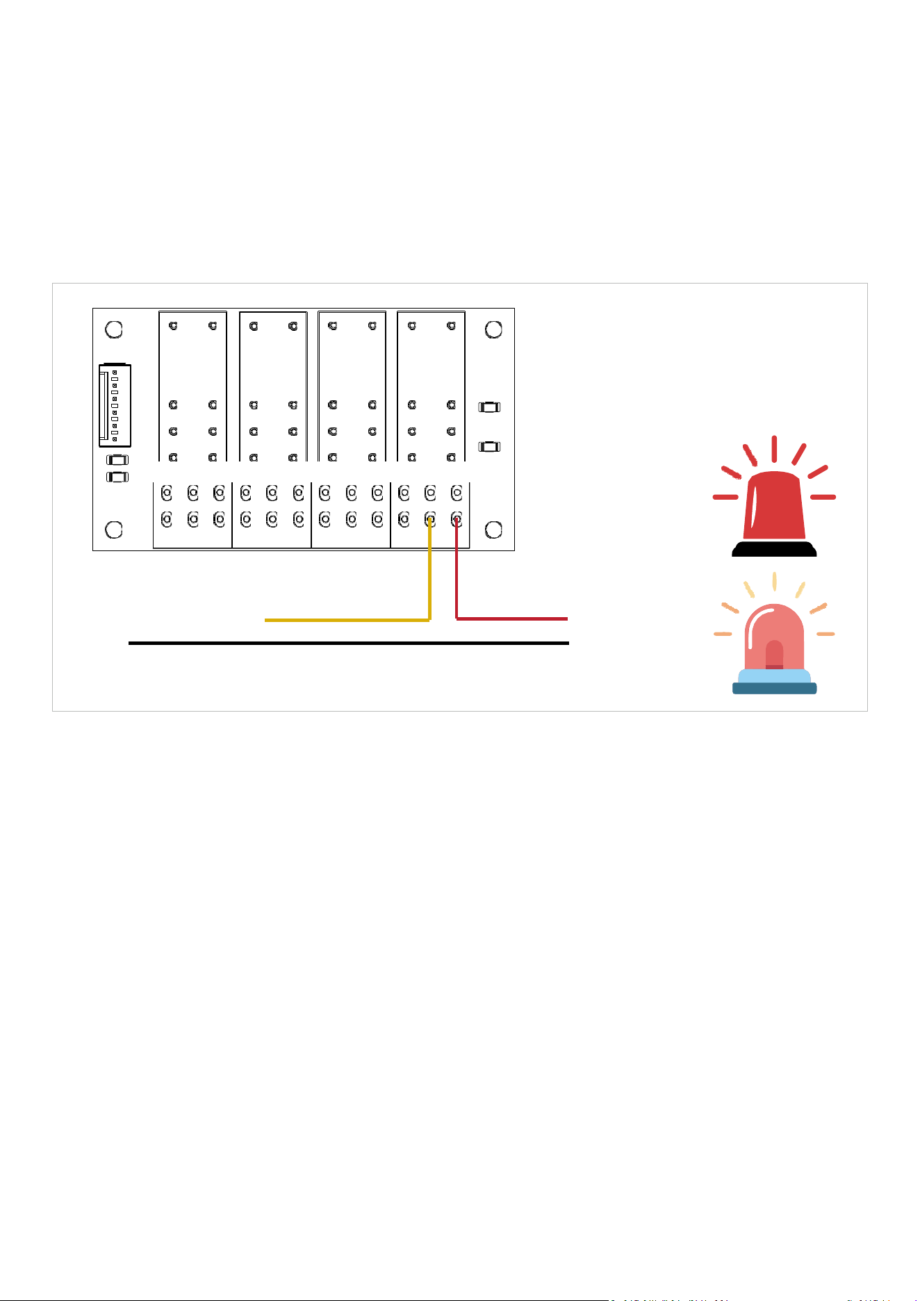
85
DAVECommercialDoorOperator—InstructionalManual
Static/StrobingLightsand Sounders
Therelaysettingsoffer3movementoptionsforwarninglightorsounder
configuration:
1.
“MOVEMENT”holdstherelayactivefortheentirecycle(defaultmodeforRelay4)
2.
“MOVEMENTWARN”,pulsestherelayat1Hzthroughouttheentirecycle
3.
“UNATTENDEDWARN”activatesfor3secondsbeforethestartofacycle
For:
•
StaticLightsuse“MOVEMENT”
•
Lightsorsounderswithbuiltinstrobingactionuse“MOVEMENT”
•
Staticlights/soundersthatrelyonthepowersupplyforstrobingactionuse
“MOVEMENTWARN”
NC C NO NC C NO NC C NO NC
C
NO
(+)externalPowerSupply
(+)LightorSounder
(‐)externalPowerSupply
(‐)LightorSounder
RELA
Y
1
RELA
Y
2
DEFA
ULT
MODE
OPEN
RELA
Y
3
RELA
Y
4
MOVEMENT
WARN

86
DAVECommercialDoorOperator—InstructionalManual
10.
MAINTENANCE& SUPPORT

87
DAVECommercialDoorOperator—InstructionalManual
DoorServiceAlerts
DAVE’sgotbrains.Hisonboardsystem—poweredbyProfileIQ™—keepsan
eyeonhowyourdoor’srunning.
Ittrackschangesovertime,spotswhenthingsstarttogoabitoff,e.g.early
signsofwear,andgivesyouaheads‐upbeforeitturnsintoabiggerissue.
You’llgetthreeclearalertswhenit’stimetogivethedooraonce‐over.No
guesswork.Nodramas.
DOORBALANCEALERT
Triggeredwhenthesystemdetectsamoderateimbalanceduringthe
door’snormaloperation.Thedoorremainsfullyoperable,andthealert
staysvisibleuntiltheuserdismissesitbyholdingthe
ontheconsole,or
thetravellimitsarereset.
•
D
oo
r
Sta
t
u
s
:
O
p
e
r
a
t
e
s
n
o
r
m
a
ll
y
.
•
L
E
D
B
e
h
a
v
i
o
u
r
:
C
o
n
s
o
l
e
L
E
D
fl
a
s
h
e
s
.
•
RelayOutput:
AlertStatusrelayisactivated.
•
C
o
n
t
rol
l
e
r
L
o
gs
:
–
CountsnumberofALERTactivations.
–
TrackscycleswithALERTmodeactive.
•
U
s
e
r
A
c
t
i
o
n
:
P
r
e
ss
S
T
O
P
w
h
il
e
t
h
e
d
oo
r
i
s
i
d
l
e
t
o
c
l
e
a
r
t
h
e
a
l
e
r
t
.
I
f
warningspersistcontactyourdoormaintenancetechnicianandask
forthedoortobeserviced.
DOORBALANCEWARNING
Triggeredbyasignificantimbalancethatcausesthedoortostopmid‐
cycle.Thesystementersdead‐man/constant‐contactmode.Thedoor
requiresservicing.Toexitthismodeandrestorenormaloperation,adoor
maintenancetechnicianmustservicethedoorandresetthetravellimits.
•
D
oo
r
Sta
t
u
s
:
D
oo
r
s
t
o
p
s
.
C
l
o
s
i
n
g
r
e
q
u
i
r
e
s
c
o
n
s
t
a
n
t
p
r
e
ss
u
r
e
o
n
a
closeinputorremote.
•
L
E
D
B
e
h
a
v
i
o
u
r
:
C
o
n
s
o
l
e
L
E
D
fl
a
s
h
e
s
.
•
R
e
l
a
y
O
u
t
p
u
t
:
A
l
e
r
t
S
t
a
t
u
s
r
e
l
a
y
i
s
a
c
t
i
v
a
t
e
d
.
•
C
o
n
t
rol
l
e
r
L
o
gs
:
–
CountsnumberofWARNINGactivations.
–
TrackscycleswithWARNINGmode active.
•
UserAction:
Requestthedoorbeservicedbyadoormaintenance
technician.Doormustberebalancedandtravellimitsresetviathe
MEMORYRESETfunction.Whilewaitingforthedoortobeserviced,
usedead‐man/constant‐contactmodetoopenandclosethedoor.
DOOR BALANCE ALERT
DOOR OPENING
KEEP CLEAR
SCREENSALTERNATE
Fig:92
DOOR BALANCE WARNING
SAFE MODE ACTIVATED
STOPPED ON CLOSING
SCREENSALTERNATE
Fig:93

88
DAVECommercialDoorOperator—InstructionalManual
DOORBALANCEFAULT
TriggeredwhenDAVEdetectsaseriousabnormality.Doortravel
stopsimmediately.Theusermustpress
toreboottheconsole,
afterwhichitrestartsindead‐man/constant‐contactmode.To
resumenormaloperation,adoormaintenancetechnicianmust
servicethedoorandresetthedoortravellimits.
•
D
oo
r
Sta
t
u
s
:
D
oo
r
S
t
o
p
s
.
D
oo
r
e
n
t
e
r
s
W
A
R
N
I
N
G
m
o
d
e
.
•
L
E
D
B
e
h
a
v
i
o
u
r
:
C
o
n
s
o
l
e
L
E
D
fl
a
s
h
e
s
.
•
R
e
l
a
y
O
u
t
p
u
t
:
A
l
e
r
t
S
t
a
t
u
s
r
e
l
a
y
i
s
a
c
t
i
v
a
t
e
d
.
•
UserAction:
»
Press
toreboottheconsole.
»
Requestadoormaintenancetechniciantoinspectandservicethe
doorandresettravellimitsviatheMEMORYRESETmenu.
»
Openandclosethedoorindeadman/hold‐to‐operatemodeuntil
thedoorhasbeenserviced
MOTOR DRIVE FAULT
0
PRESS
TO RESET
SCREENSALTERNATE
Fig:94
DOOR BALANCE WARNING
SAFE MODE ACTIVATED
89
DAVECommercialDoorOperator—InstructionalManual
MaintenanceRequirements
SAFETYWARNING
Failuretofollowtheseinstructionsmayresultininjury,equipmentdamage,orvoidingofwarranty.
ReadBeforePerformingMaintenance
Toensuresafeservicingofthisoperator,pleasefollowtheseguidelines:
1.
Disconnectpowertotheoperatorbeforestartingany
maintenanceor inspection.
2.
Performasafetycheckoftheentiresystemtoidentifyany
faultsor hazards.
3.
Ensurethedoorareaisclearofpeople,vehicles,andany
obstructions.
4.
Thisproductisnotuser‐serviceable.Maintenancemustonly
becarriedoutbytrainedandauthorisedtechnicians.
AVERTISSEMENTDESÉCURITÉ
Lenon‐respectdecesinstructionspeutentraînerdesblessures,desdommagesàl’équipementoul’annulationde
lagarantie.
Àlireavantd’effectuerlamaintenance
Pourassurerunentretiensécuritairedecetopérateur,veuillezsuivrecesconsignes:
1.
Débranchezl’alimentationdel’opérateuravantde
commencertouteopérationdemaintenanceou
d’inspection.
2.
Effectuezunevérificationdesécuritédel’ensembledu
systèmeafind’identifiertoutdéfautoudanger.
3.
Assurez‐vousquelazonedelaporteestdégagéedetoute
personne,véhiculeouobstruction.
4.
Ceproduitn’estpasréparableparl’utilisateur.La
maintenancedoituniquementêtreeffectuéepardes
techniciensformésetautorisés.

90
DAVECommercialDoorOperator—InstructionalManual
Item
Action
Required
Monthly
Check
Quarterly
Check
Annual
Check
SafetyDevices
Checkalignment
Checkoperation
x
Sprockets
Checktightnessofset
screws
x
DriveChain
Checksprocketalignment
andchaintension
Lubricate
x
Coupler
Checkalignment
Checktightnessof
fasteners
x
Fasteners
Locateallfastenersand
checktightness.
x
ManualHauling
Checkoperation
x
Powercord
Checkforwearordamage
x
Shafts
Checkforwearordamage
x
Firmware
Updatecontrolsoftware
x
NOTES
•
Donotlubricatethemotororreducer.
•
Motorbearingsratedtospecification.
x
:
I
n
s
p
e
c
t
i
t
em
.
S
e
r
v
i
c
e
o
rr
e
p
l
a
c
e
i
f
/
w
h
e
n
d
eeme
d
f
a
u
l
t
y

91
DAVECommercialDoorOperator—InstructionalManual
Troubleshooting Guide
ISSUE
POSSIBLECAUSES
REMEDY
NothingonLCDscreen
Batteriesnotinstalled
Installfreshbatterieswithcorrectpolarities
Batteriesinsertedwrongway
Re‐installbatterieswithcorrectpolarities
Lowbatteries
Installfreshbatterieswithcorrectpolarities
Ifconsoleiswired,cabletodrive
unit&orconsoleisloose,wired
incorrectlyornotconnected
Ifwiredtounitcheckwiringcableconnectionatconsole&
driveunitmaincontrolboard
Ifconsoleispoweredbyoptional
5VDCpoweradaptor,power
adaptorisnotconnectedornot
turnedonatpowersource
Check&reconnect5Vpoweradaptorandreapplypower
NoyellowandgreenLED
litonoperatorcartridge
Missingpower
Restorepowertodriveunit
Wrongtypecartridgeused
Usecorrectcartridge
Powerinletwiringissue
Restorepowertodriveunit
Blownfuse
Changefuse
Faultypowercord
Replacepowercord
Awaitingconnectionbut
doorworksfrombuttons
Nopowertodriveunit
Switchpoweron
Consolenotpairedtodriveunit
Pairconsoletodriveunit
Interference
Usewiredconnectionbetweenconsole&driveunit
Consoleistoofarawayfromdrive
unit
Consoleneedtobewithin15metresofdriveunit
Bluetoothpairing
successfulbutconsole
buttonsnotfunctioning
RFbuttonsnotpaired
GotoMenu5.6andfollowRFbuttonpairinginstructions
Haulingchainnotworking
Chainwheelnotreturningtoits
naturalposition
Checkandfreehandchain
Disengagementharnessfaultyor
notconnectedproperly
Replacedisengagementharness
Individualwiredtriggering
devices(keyswitches
pushbuttonsetc)not
functioning.
Wireddevice(s)faultcreatingfault
atwiredinput.
CheckOSC,OPN,CLS,GPA,GPB&OVconnection&
wiring.Checkscreenpromptforadviceonwhichproductis
causingissue.GotoMenu3control&safetyinputstatusto
identifyissue.

92
DAVECommercialDoorOperator—InstructionalManual
ISSUE
POSSIBLECAUSES
REMEDY
Stop(stop)active
preventingunitoperation
LinkmissingorloosefromSTPOV
terminalonmaincontrolboard
InsertlinkintoSTP&OVterminal
Tensionactivemessage
onconsole
Wiredcabletensioning(derailing)
deviceintoTEN&0Vcreatingfault
Checkscreenpromptforadviceonwhichdeviceiscausing
issue.GotoMenu3control&safetyinputstatustoidentify
issue.
Missing10Kresistorfrom0VTEN
terminalonmaincontrolboard
Insert10K_0.25wattresistorinto0VandTENterminal
Missingwirelinkfrom0VSTP
terminalonmaincontrolboard
Insertwirelinkbetween0VandSTPterminal
Interlockactivemessage
onconsole
DockleveldevicewiredtoINT&
OVcreatingfault
Checkscreenpromptforadviceonwhichdeviceiscausing
issue.GotoMenu3control&safetyinputstatustoidentify
issue.
Missing10Kresistorfrom0VINT
terminalonACB06PCBA
Insert10K_0.25wattresistorinto0VandINTterminal
“ACTIVATEKEYTOENTER
MENU”messageon
console
Keyswitchonconsoleisinlock
position
Turnkeyswitchanticlockwise
Lostkey
Contactsupplierfornewkey
Faultykeyswitchharnessornot
pluggedproperly
Replaceharness
Limitsnotsetting
Positioningencoderorharness
faulty
Replacelimitassembly
Operatormakesnoisebut
doornotmoving
Dooristooheavytolift
Checkdoorweightiswithinoperatorcapability
specificationandingoodworkingorder
Keyfromdriveshaftmissing
Insertkeyinthekeywayandtightentwogrubscrews
Slowstopistooquick
Slowratenotadjustedcorrectly
Edit/adjustslowrate‐higherthevaluequickerthedoorwill
stop
Unitwillopenbutnotclose
SafetydeviceheldactiveSD1SD2
SD3
Checkscreenpromptforadviceonwhichdeviceiscausing
issue.GotoMenu3control&safetyinputstatustoidentify
issue.Checkalignment,batterieswiringofsafetydevices

93
DAVECommercialDoorOperator—InstructionalManual
ISSUE
POSSIBLECAUSES
REMEDY
POSITIONSENSORFAULT
XXXX
*
Issuewiththepositioningencoder
sensor.
Resetfaultandtrytooperateagain.
Ifproblempersistsreplacethepositioningencoder.
POSITIONSENSORFAULT
7A00
Lossofcommunicationwiththe
positionencoder.
Resetfaultandtrytooperateagain.
Ifproblempersists,checkwiringtopositioningencoder.If
wiringisingoodorder,thenreplacepositioningencoder.If
problempersists,replacemaincontrolboard.
DIRECTIONFAULTXXXX
Operatorhasdetectedthatthe
doorhastraveledinthewrong
direction.
Resetfaultandtrytooperateagain.
MOTORDRIVEFAULT
1
Overcurrentfault‐Likelycaused
byexcessivemotorload.
Resetfaultandtrytooperateagain.Ifproblempersiststhen
checkdoorconditionincludingbalance.
MOTORDRIVEFAULT21
Over‐currentorover‐temperature
fault
MOTORDRIVEFAULT61
Over‐currentorover‐temperature
fault
MOTORDRIVEFAULT
XXXX
Resultofacombinationofmore
thanoneoftheabovecodes
Resetfaultandtrytooperateagain.
POSITIONWRAPERROR
XXXX
Causedbydoormovingoutsideof
expectedrangeofmovement.
Attempttomovedoorbackinintonormaloperatingrange
usingmanualchainandthenresetfault.
CLOSESETERROR
Profilingcycleafterlimitsetting
hasbeeninterruptedbyasafetyor
controlinput.
AcknowledgeerrorbypressingSETandthenrepeatlimits
setup.
OPENSETERROR
MOTORCOMMSERROR
FFFF
Lossofcommunicationsbetween
maincontrolboardandmotor
controller.
ResetFaultandtrytooperateagain.
Ifthefaultonlyoccurswhenthedoorisclosingonly,then
rebalancethedoor.
Iffaultisreportedcontinuouslythenreplacemaincontrol
board.
*Xcanrepresentanynumeral
Ifanylistedactiondoesn’tresolveoranyotherfaultcodepresents,
contactTechSupport

94 DAVECommercialDoorOperator—InstructionalManual
SUPPORT
Forassistancewiththisproduct,pleasecontactAutomaticTechnologyusingthe
regionalphonenumbersandwebsiteslistedbelow,orbyemailing
YoucanalsovisitDAVE’sproductpageforthelatestversionofthemanualandother
technicaldocumentation:www.automatictechnology.com/dave
PRODUCTWARRANTY
ForfullwarrantytermsandconditionsrelatingtoDAVEproducts,please
visit: www.automatictechnology.com/warranty
CONTACT
AUSTRALIA
W: https://www.automatictechnology.com/au
P: 1300133944
NEWZEALAND
W: https://www.automatictechnology.com/nz
P: 0800673637
NORTHAMERICA
W: https://www.automatictechnology.com
P: 1‐800‐934‐9892