Drying cabinet
DC7784V.W.U
USER MANUAL
Read the user manual before using the machine.
879787en.indd 1879787en.indd 1 18. 04. 2024 15:07:1718. 04. 2024 15:07:17

Dear ASKO customer,
Congratulations on the choice you have made, and welcome to the
ASKO family, a global family with its roots in Sweden.
We at ASKO thank you for your trust and hope that you will enjoy
using your new drying cabinet.
A good drying cabinet should be well designed, dry clothes well,
have a low environmental impact, be user- iendly, save time and
energy, have a long service life and be reliable. ASKO meets all these
requirements.
When you buy an ASKO product you can be sure that the inside is
just as good as the outside and that the ethics and morality that go
into manufacturing this product are just as high as the quality and
function you are getting. at's what Swedish quality is all about.
Before using the product for the rst time, please read the user
instructions and the advice on caring for the product. is will
help you get the best possible results om your product and all its
functions.
If you have any questions, do not hesitate to call us or to contact us
through our website.
Best wishes om Sweden and the ASKO team.
879787en.indd 2879787en.indd 2 18. 04. 2024 15:07:3318. 04. 2024 15:07:33

3
CONTENTS
IMPORTANT SAFETY
INFORMATION 5
Important safety instructions 6
Installation and connection 9
FOR A GOOD ENVIRONMENT 10
Packaging materials 10
Management of end-of-life drying
cabinet 10
COMPONENTS 11
Control panel 12
Language 13
Unpacking 14
DOOR REVERSING 15
INSTALLATION 20
Location requirements 20
Installation instruction –
Laundry care concept 21
Mounting into custom cabinetry 22
Ventilation connection 25
Ventilation requirements 26
Evacuation / air supply 27
Connection to evacuation 27
Electrical connection 29
BEFORE USING THE DRYING
CABINET 30
OPERATION 31
Arranging laundry for drying 31
Cabinet equipped with coat
hanger rack and shoe rack 31
User advice 31
Air fl ow 32
Drying programs 33
Child lock 34
Start automatic program 35
Starting a manual program 35
User advice 36
SETTING DRYING PROGRAMS 37
Programming mode 37
Parameter list 38
Adjustment 40
Procedure 41
Restoring to factory setting 41
CARE 42
Cleaning 42
Replacement part 42
OVERHEAT CUT-OUT 43
TROUBLESHOOTING 44
SERVICE AND WARRANTY 45
Service 47
TECHNICAL DATA 48
Energy consumption and drying
times 48
879787en.indd 3879787en.indd 3 18. 04. 2024 15:07:3318. 04. 2024 15:07:33
4
THIS USER MANUAL
The contents of this user manual describe the function and operation of the drying cabinet,
as well as instructions for installation and maintenance.
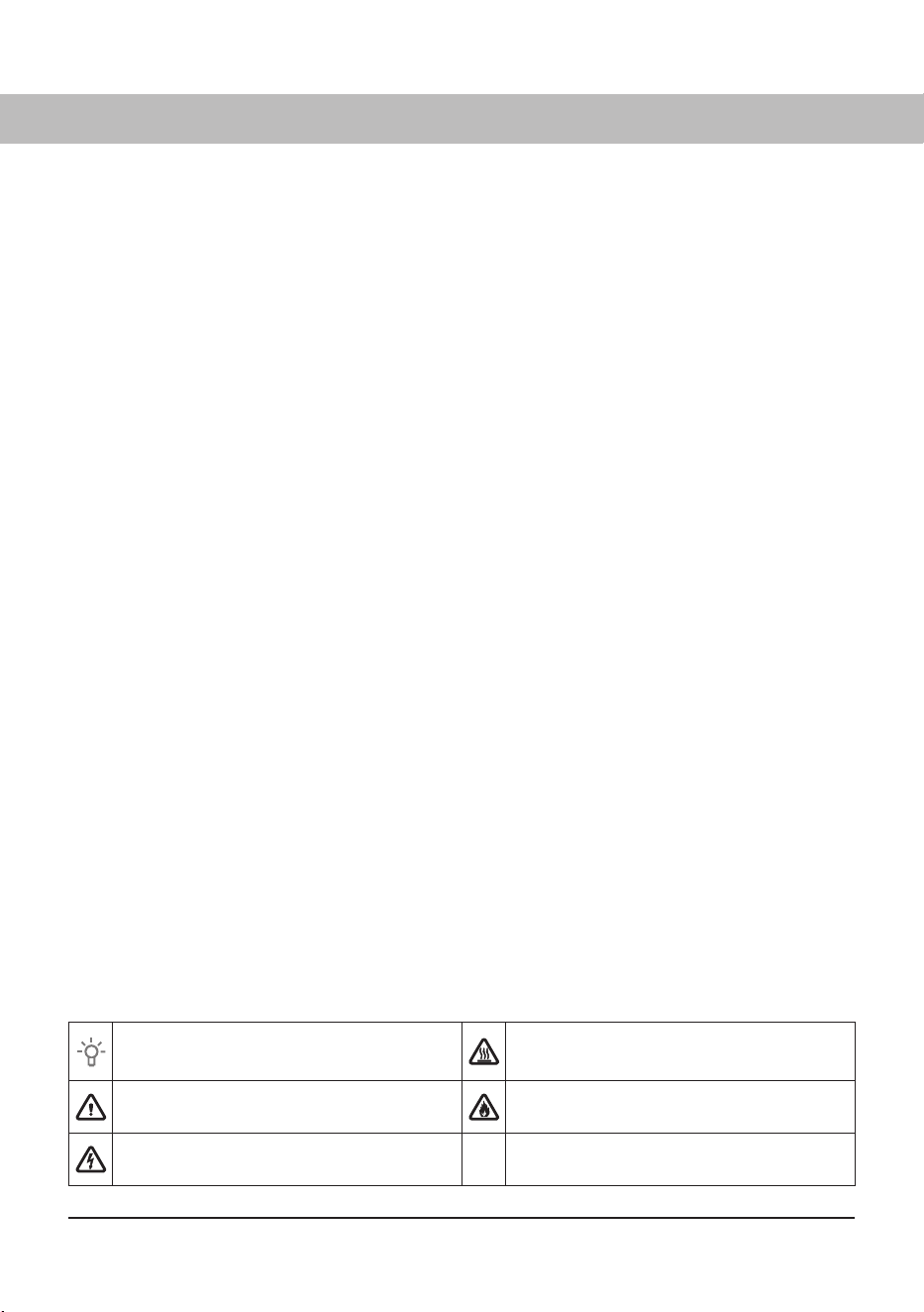
The following symbols are used throughout the manual and they have the following
meanings:
Information, advice, tip, or
recommendation
Warning – danger of hot surface
Warning – general danger Warning – danger of fi re
Warning – danger of electric shock
879787en.indd 4879787en.indd 4 18. 04. 2024 15:07:3318. 04. 2024 15:07:33

5
This drying cabinet meets applicable safety requirements. Incorrect
use may, however, lead to injuries and damage to objects.
The advice and caution notices in this manual have been written
to enable you to avoid incorrect use and unnecessary risks of
accidents, and should be read before installing and using the drying
cabinet.
IMPORTANT SAFETY INFORMATION
CAUTION: This equipment is intended only to be used to dry
fabrics washed in water.
The appliance is not intended for use by persons (including
children) with various disabilities or inadequate experience
and knowledge.
They may use the appliance only under supervision or
if they have received instructions on how to use the
appliance form a person who is responsible for their
safety.
Children must be supervised to ensure that they do not
play with the appliance.
The drying cabinet must be installed and kept indoors.
If the power cord is damaged, it must be immediately re-
placed, and this must be done only by the manufacturer,
the manufacturer's service agent or similarly qualified
persons in order to prevent danger.
Follow ASKO instructions in repair and replacement of
parts.
879787en.indd 5879787en.indd 5 18. 04. 2024 15:07:3418. 04. 2024 15:07:34

6
IMPORTANT SAFETY INSTRUCTIONS
WARNING – To reduce the risk of fi re, electric shock, or
injury to persons when using your appliance, follow basic
precautions, including the following:
1 Read all instructions before using the appliance.
2 Do not dry articles that have been previously cleaned
in, washed in, soaked in, or spotted with gasoline, dry-
cleaning solvents, or other fl ammable or explosive
substances, as they give off vapors that could ignite or
explode.
3 Risk of suff ocation and injury from entrapment: Do
not allow children to play on or in the appliance. Close
supervision of children is necessary when the appliance is
used near children.
4 Before the appliance is removed from service or
discarded, remove the door to the drying compartment.
5 Do not install or store this appliance where it will be
exposed to the weather.
6 Do not tamper with controls.
7 Do not repair or replace any part of the appliance or
attempt any servicing unless specifi cally recommended
in the user-maintenance instructions or in published user-
repair instructions that you understand and have the skills
to carry out.
879787en.indd 6879787en.indd 6 18. 04. 2024 15:07:3418. 04. 2024 15:07:34
7
8 Do not use heat to dry articles containing foam rubber or
similarly textured rubber-like materials.
9 Keep area around the exhaust opening and adjacent
surrounding areas free from the accumulation of lint, dust,
and dirt.
10 The interior of the appliance and exhaust duct should be
cleaned periodically.
11 Do not place items exposed to cooking oils in your drying
cabinet. Items contaminated with cooking oils may
contribute to a chemical reaction that could cause a load
to catch fi re. To reduce the risk of fi re due to contaminated
loads, the fi nal part of a drying cabinet cycle occurs
without heat (cool down period). Avoid stopping a drying
cabinet before the end of the drying cycle unless all items
are quickly removed and spread out so that the heat is
dissipated.
12 Do not use replacement parts that have not been
recommended by the manufacturer (e.g. parts made at
home using a 3D printer).
WARNING – Keep the ventilation slits on the housing
unobstructed.
879787en.indd 7879787en.indd 7 18. 04. 2024 15:07:3418. 04. 2024 15:07:34
8
For a grounded, cord-connected appliance:
GROUNDING INSTRUCTIONS
This appliance must be grounded. In the event of malfunction
or breakdown, grounding will reduce the risk of electric shock
by providing a path of least resistance for electric current.
This appliance is equipped with a cord having an equipment-
grounding conductor and a grounding plug. The plug must be
plugged into an appropriate outlet that is properly installed and
grounded in accordance with all local codes and ordinances.
WARNING – Improper connection of the equipment-
grounding conductor can result in a risk of electric shock.
Check with a qualifi ed electrician or service representative or
personnel if you are in doubt as to whether the appliance is
properly grounded.
Do not modify the plug provided with the appliance: if it will
not fi t the outlet, have a proper outlet installed by a qualifi ed
electrician.
SAVE THESE INSTRUCTIONS FOR FUTURE REFERENCE!
879787en.indd 8879787en.indd 8 18. 04. 2024 15:07:3418. 04. 2024 15:07:34
9
WARNING!
Install the drying cabinet according to the
manufacturer’s instructions and local codes.
WARNING!
Drying cabinet installation must be performed by
a qualified installer.
WARNING!
To reduce the risk of severe injury or death,
follow all installation instructions.
WARNING!
Save these instructions.
WARNING!
Do not install a drying cabinet with flexible
plastic venting materials. If flexible metal (foil
type) duct is installed, it must be of a specific
type identified by the appliance manufacturer
as suitable for use with drying cabinets. Flexible
venting materials are known to collapse, be
easily crushed, and trap lint. These conditions
will obstruct drying cabinet airflow and increase
the risk of fire.
WARNING!
• The appliance shall not be exhausted into
a chimney, a wall, a ceiling, an attic, a crawl
space, or a concealed space of a building;
• Only rigid or fl exible metal duct shall be used
for exhausting;
• Maximum duct length shall be 8 feet (2.4 m)
and maximum number of bends shall be 4;
• The total length of fl exible metal duct shall not
exceed 8 feet (2.4 m);
• The duct shall not be assembled with screws
or other fastening means that extend into the
duct and catch lint.
WARNING!
Do not install a booster fan in the exhaust duct.
INSTALLATION AND CONNECTION
879787en.indd 9879787en.indd 9 18. 04. 2024 15:07:3418. 04. 2024 15:07:34
10
PACKAGING MATERIALS
The packaging that protects the drying
cabinet against damage in transit has been
chosen with concern for the environment in
mind and is therefore recyclable.
Packaging that is returned to the material
cycle means reduced consumption of raw
materials and a smaller volume of waste.
FOR A GOOD ENVIRONMENT
MANAGEMENT OF END-OF-LIFE
DRYING CABINET
When the drying cabinet has reached the
end of its useful life, it must be taken to a
recycling center for disposal.
Many parts of the drying cabinet can be re-
used, but it also contains other material that
must be handled correctly.
You should therefore never leave the drying
cabinet or parts of the cabinet for collection
with household waste, as this may lead to
risks to health and cause damage to the
environment.
The end-of-life drying cabinet should
instead be taken to a recycling center.
Check with your dealer if necessary.
All the plastic parts of the drying
cabinet are marked with internationally
standardised symbols.
The parts of the drying cabinet can
therefore be recycled in an environmentally
sound manner by waste separation.
879787en.indd 10879787en.indd 10 18. 04. 2024 15:07:3518. 04. 2024 15:07:35
11
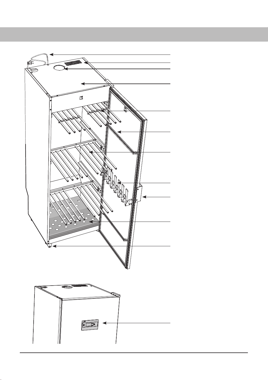
COMPONENTS
Power Cord
Air inlet
Moist air outlet
Heating and fan components are
combined in the top of the cabinet
in a Fan Unit.
Clothes hanger rack
Door hangers
Three extendible hanging
sections
(The illustration shows extended
sections)
Glove hangers
Door "handle", right or left-hand
version
Shoe rack
Adjustable feet (x4)
Control panel
879787en.indd 11879787en.indd 11 18. 04. 2024 15:07:3518. 04. 2024 15:07:35
12
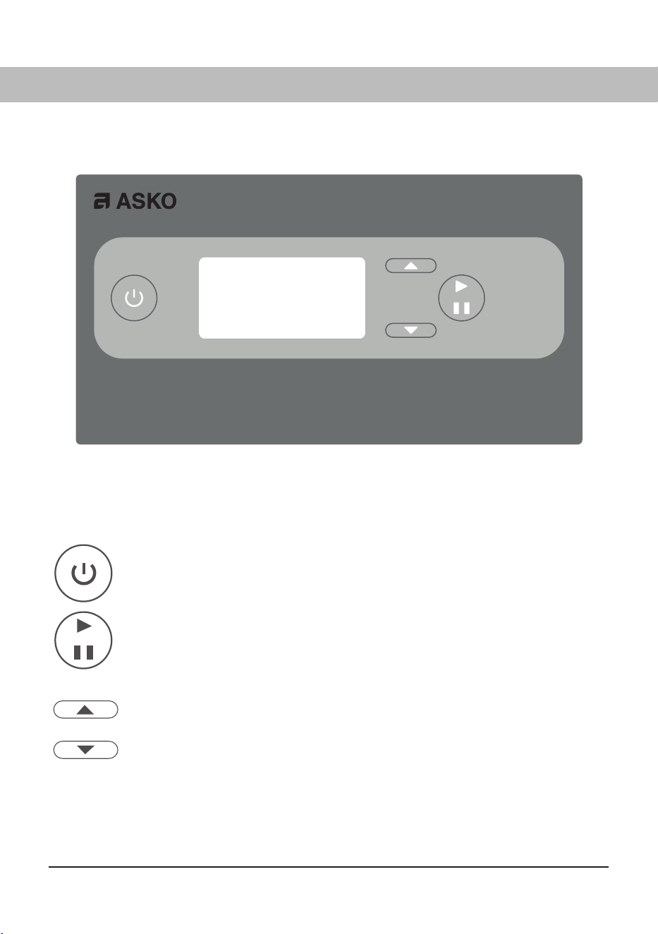
CONTROL PANEL
The drying cabinet is equipped with four automatic and four manual drying programs suited to diff erent
types of clothing. The programs are set using the buttons on the menu panel. Four languages can be
chosen.
BUTTONS
ON/OFF
START Starts and
STOP Stops the drying program
OK Confirms the selection of programs, functions and settings
UP ARROW, increase values or browse between programs.
DOWN ARROW, reduce values or browse between programs.
DISPLAY
The display has two rows with 6 characters on each row. During the drying process the selected drying
program and a rolling bar indicating that the process is in progress are shown.
879787en.indd 12879787en.indd 12 18. 04. 2024 15:07:4618. 04. 2024 15:07:46
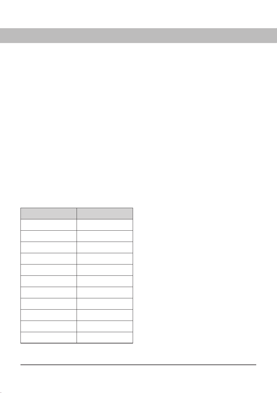
13
Language symbol Display language
0 English
1 Swedish
2 Norwegian
3 Danish
4 Finnish
5 Italian
6 French
7 German
8 Spanish
9 Portuguese
10 Dutch
SETTING
1 Make sure that the ON/OFF switch on the
drying cabinet is off . The display is unlit.
2 Hold down the UP ARROW and DOWN
ARROW buttons and press the ON/OFF
switch to the “ON” position. The display
lights up and on the top row shows “P105”
flashing, which is the parameter for
language setting. If a diff erent value is
shown, use the UP ARROW or DOWN
ARROW buttons to browse to the correct
parameter.
3 Press START/STOP to confirm.
The row for current language now flashes.
The languages have a numerical symbol as
shown in the list below.
4 Browse to the desired language with the UP
ARROW or DOWN ARROW buttons.
5 To save the set value, press START/ STOP.
6 To return to operating mode, press DOWN
ARROW and START/STOP.
LANGUAGE
The following languages can be chosen: English, Swedish, Norwegian, Danish, Finnish, Italian,
French, German, Spanish, Portuguese and Dutch.
879787en.indd 13879787en.indd 13 18. 04. 2024 15:07:4618. 04. 2024 15:07:46
14
UNPACKING
CAUTION!
The drying cabinet must be handled carefully if it
is standing unsupported on its pallet.
RISK OF TIPPING OVER
Make sure that the product has not been damaged
in transit Any damage incurred in transit must be
reported to the dealer within 7 days.
After unpacking, check that the product is in-
tact. Damage, defects and any missing parts
must be reported to the dealer immediately.
Check that all transport securing devices have
been removed before connecting the drying
cabinet.
Packaging materials such as plastic and
styrofoam should be kept out of the reach of
children.
Complete delivery must include:
Cabinet with installed fan unit
Assembly kit
User Manual
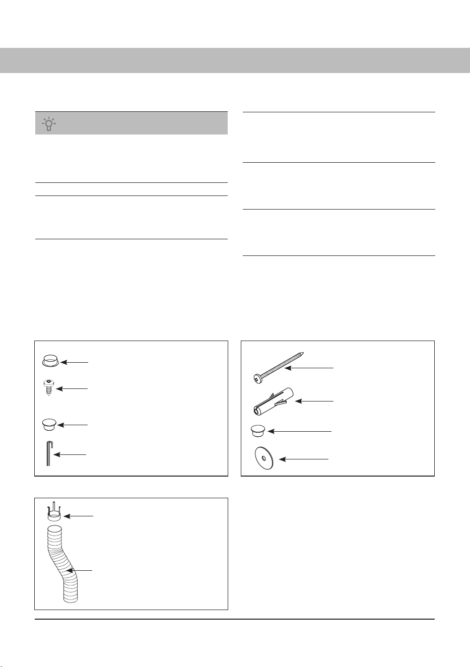
ASSEMBLY KIT
- for cabinet - for attachment to wall
Spigot (1)
Mounting screw for spigot (2)
Cover plug, white (4) for
adjustable feet
Allen key (1)
Screw TRX 5x70
zinc-plated (2)
Anchor plug (2)
Cover plug, white (2)
Washer NB (2)
- not supplied with a drying cabinet
Draft stabilizer (1)
Hose (1)
879787en.indd 14879787en.indd 14 18. 04. 2024 15:07:4618. 04. 2024 15:07:46
D
D
D
D
D
15
DOOR REVERSING
The pictures below illustrate reversing the door from right to left hinge.
Door Reversing kit (Product code: 721529)
For reversing, a door reversing kit must be ordered from the supplier of the cabinet. The kit consists of
a new upper hinge, as the left and right hinges are not interchangeable. The kit also includes a control
cable for fi tting in the door with associated hinge bushing.
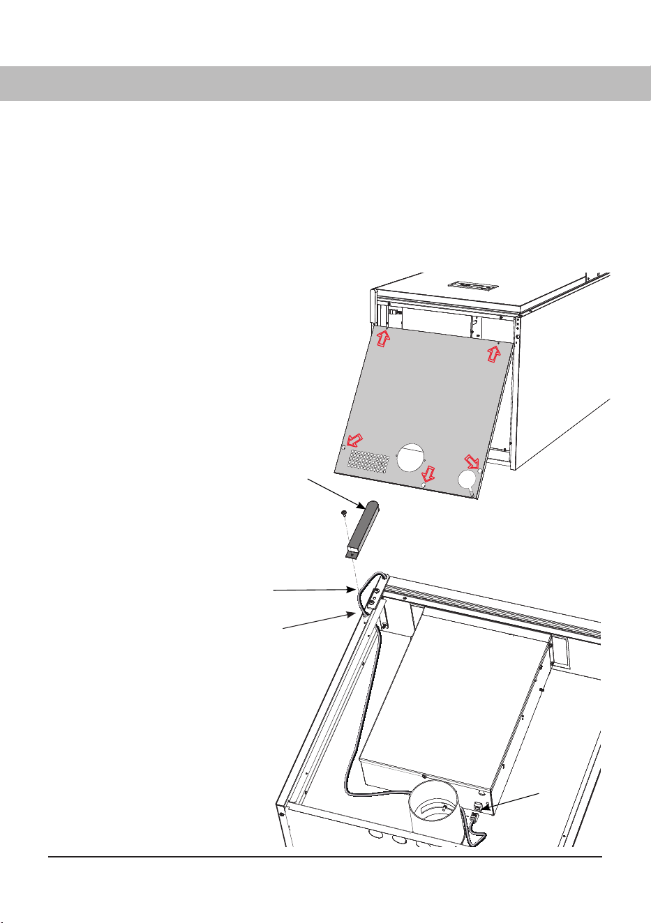
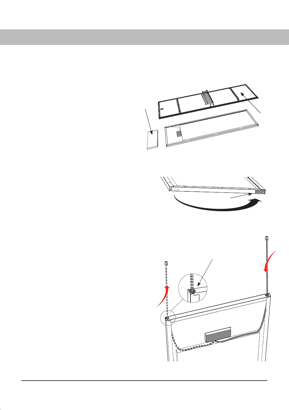
1 Remove the cover in the top
of the drying cabinet. This is
attached with five screws at
the marking arrows.
2 Remove the protective cover
(1) of the upper hinge and
release the control cable (2).
3 Separate the control cable
from the fan unit with the quick
connector (3) and pull the
cable through the hole (4).
Lay the cabinet down carefully on its
back.
2
1
3
4
Fan unit
879787en.indd 15879787en.indd 15 18. 04. 2024 15:07:5018. 04. 2024 15:07:50
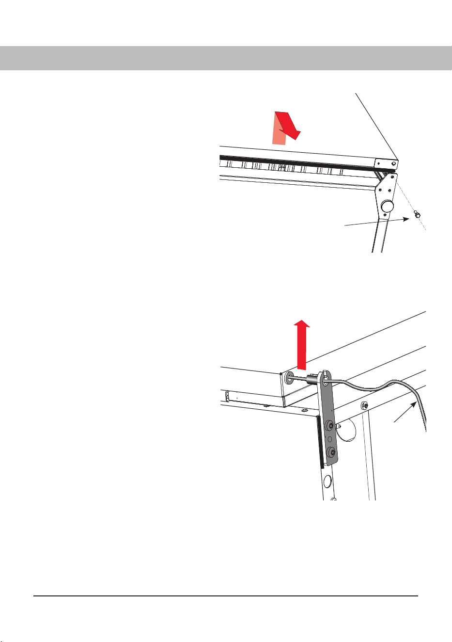
6
5
16
Upper hinge joint with the door pulled down so that
the hinge pin is freed
4 Unscrew the lower hinge pin (5).
Raise the door slightly from the
bottom edge and detach it from the
upper hinge, to the extent that the
hinge pin is visible. The pin has a
recess for the control cable.
5 Carefully pull the control
cable (6) out of the recess
in the hinge pin.
6 The door, together with the control
cable, is now free and can be set
aside.
879787en.indd 16879787en.indd 16 18. 04. 2024 15:07:5318. 04. 2024 15:07:53
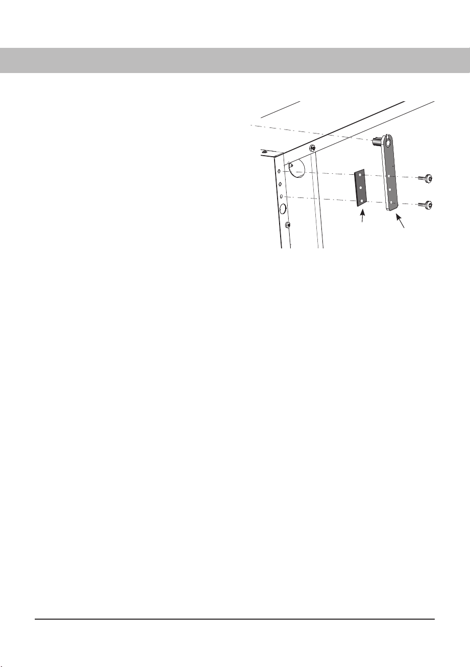
7
8
17
7 Detach the upper hinge (7) with hinge
washer (8). Discard the hinge.
8 Install the new replacement hinge on the
opposite side and move the hinge washer
across.
The hinge forms part of the door
reversing kit, which can be ordered from
the dealer of the drying cabinet.
879787en.indd 17879787en.indd 17 18. 04. 2024 15:07:5518. 04. 2024 15:07:55
12
10
9
11
18
9 Lay the door down with the inside
facing up on a non-damaging
surface.
10 Detach the inner plate (9) with
magnetic strip, door hangers and
glove hangers. Screws are beneath
the magnetic strips.
Remove the insulation (10).
11 Detach and transfer the
reinforcement panel and lower
hinge bushing (11) in the door to
the opposite side.
12 Detach existing control cable from
control panel and pull cable out with
hinge bushing (12). Discard the
cable as there is a new complete
cable in the door reversing kit.
Fit the new cable on the opposite
side - press the bushing fi rmly into
the hole and connect the cable to the
control panel outlet.
13 Move back the insulation and inner
plate with magnetic strips and, if
applicable, hangers.
Re-attachment in the door
879787en.indd 18879787en.indd 18 18. 04. 2024 15:07:5518. 04. 2024 15:07:55
13
14
19
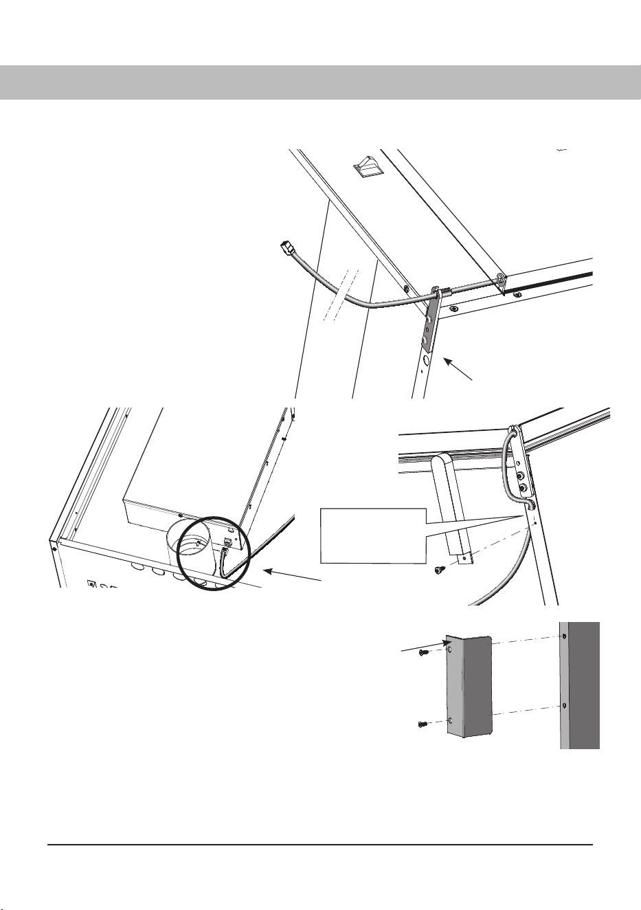
14 Introduce the operating cable
through the recess in the new up-
per hinge and slide the door up on
the hinge pin.
15 Install the lower hinge pin.
Make sure that the hinge pin is
tightened fi rmly.
16 Connect the control panel (13) to
the connector in the upper part of
the drying cabinet.
17 Refi t the drying cabinet cover
which was removed under 1.
Lay the door in position
New hinge
Fan unit
The control cable
must be pulled
through the hole.
Raise the cabinet
19 Raise the cabinet and place it in position and
secure the cabinet to the wall.
Transfer the door handle
18 Transfer the handle (14) to the other side.
Fit the cover plugs for the old holes by
hand. Cover plugs are supplied in the
assembly kit.
879787en.indd 19879787en.indd 19 18. 04. 2024 15:07:5718. 04. 2024 15:07:57
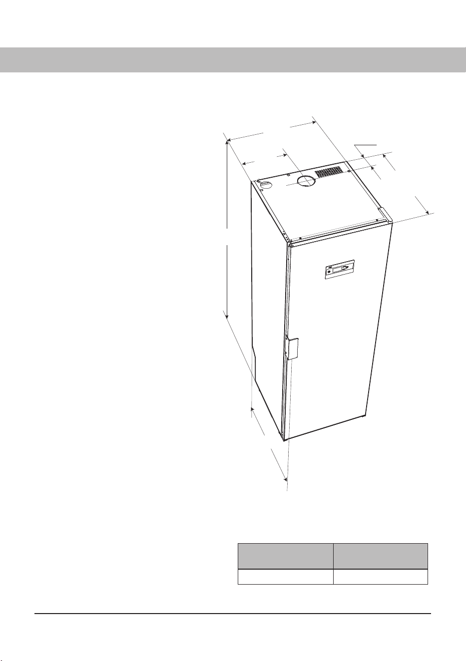
A
23 7/16"
(595 mm)
11 3/4"
(298 mm)
3 15/16"
(100 mm)
23 15/16"
(608 mm)
25"
(635 mm)
20
If the drying cabinet is to be installed
connected to air exhaust ventilation, this
must be available in the room.
There must be an grounded outlet
socket within a distance of 78¾" (2 m)
from the upper part of the drying cabinet.
The drying cabinet has a 78¾" (2 m)
long grounded outlet lead with a plug
connected.
The power cord should be located such
that there is no need for an extension
cable.
It must be possible to reach the outlet
easily after the drying cabinet has been
installed.
This must also be kept in mind if the
drying cabinet is built into woodwork
or similar. See also the section on
‘Electrical connection’.
The fl oor where the cabinet is located
must withstand a weight of around
132.28 lbs (60 kg).
The fl oor must be level with a max drop
of 63/64" (2.5 cm) under the cabinet.
The drying cabinet is intended only for
installation indoors with a temperature
above 32°F (0°C).
The drying cabinet must not be placed in
an environment in which high-pressure
water is used for cleaning.
Cabinet designation A inch
(mm)
DC7784V 727⁄16" (1840 mm)
Dimensions in inches,
mm in brackets ( )
LOCATION REQUIREMENTS
INSTALLATION
879787en.indd 20879787en.indd 20 18. 04. 2024 15:07:5918. 04. 2024 15:07:59
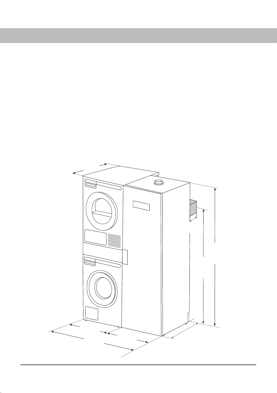
4"
(102 mm)
23 15/16"
(608 mm)
46 7/8"
(1190 mm)
23 7/16"
(595 mm)
23 7/16"
(595 mm)
65 1/8"
(1654 mm)
72 7/16"
(1840 mm)
27 7/8"
(708 mm)
21
INSTALLATION INSTRUCTION – LAUNDRY CARE CONCEPT
Instruction for installing the drying cabinet next to ASKO washing machines, hidden-helpers and
tumble dryers.
If your washing machine is slightly less deep than the drying cabinet you only have to fi x the drying
cabinet to the wall and place the other appliances next to it.
If your washing machine is deeper than the drying cabinet you will need to add a 4 inch (102 mm)
distance (wood stud for example) to achieve aligned installation together with the other appliances.
The distance should be attached to the wall for fi xed installation.
This distance is needed if you have bought a XL appliance listed below;
W4114 T411
W6124 T611
879787en.indd 21879787en.indd 21 18. 04. 2024 15:08:0018. 04. 2024 15:08:00
2
A
3
4
5
1
22
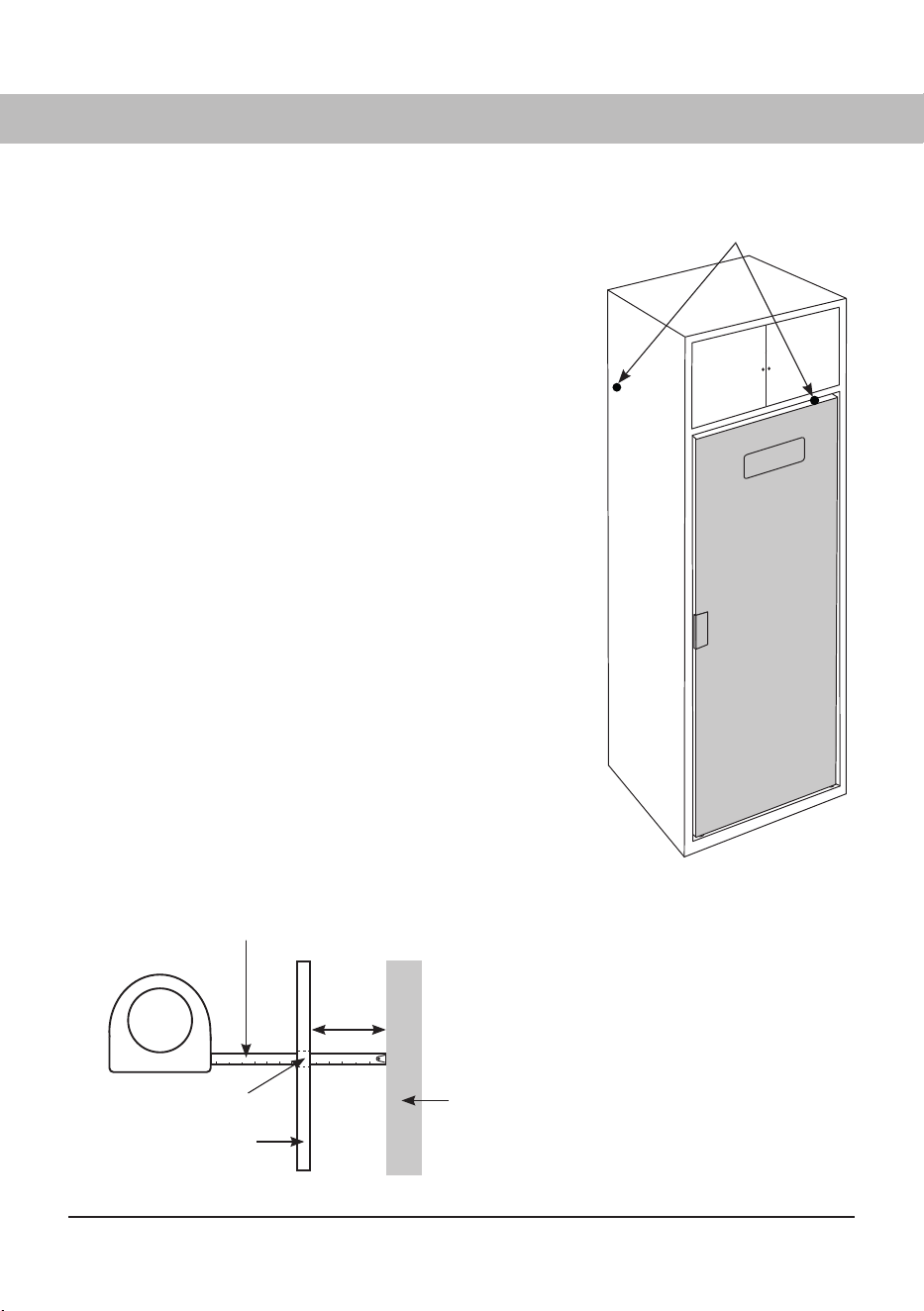
MOUNTING INTO CUSTOM CABINETRY
1 Keep the door taped closed until the cabinet is in
place. Slide the drying cabinet in so that it is fl ush
and centered with the cabinet face.
2 Plug in the power cord to the electrical outlet, making
sure that the cord is not crimped and that the plug
can be easily unplugged without moving the unit.
3 Remove the tape and open the door. Pull out
the upper hanger section. Measure and note the
distance between the drying cabinet’s rear wall and
the wall behind the drying cabinet. See dimension
“A” in the fi gure.
4 Mark the location of the holes on the wall with a
pencil.
5 Push back the hanger section, close the door and
tape it closed. Pull out the entire drying cabinet.
6 Use a wood shim with thickness “A” according to
point 3 as a gauge block. The shim must:
a) be divided into two parts for allowing free air fl ow
behind the drying cabinet. Length ~6 in. (15 cm)
each.
b) have a thickness of minimum ½" (13 mm).
7 Screw the shims with two screws each to the wall
behind the drying cabinet so that it covers the
marked holes according to point 4. Use screws with
appropriate length.
1. Minimum ventilation openings in the top
and between the cabinet and the rear
wall must be ½” (13 mm).
2. Tape measure
3. Mounting hole
4. Rear drying cabinet wall
5. Wall behind drying cabinet
Slide the drying cabinet in so that it is fl ush
and centered with the cabinet face.
879787en.indd 22879787en.indd 22 18. 04. 2024 15:08:0018. 04. 2024 15:08:00
2
1
~6” (15 cm)
4
3
5
6
23
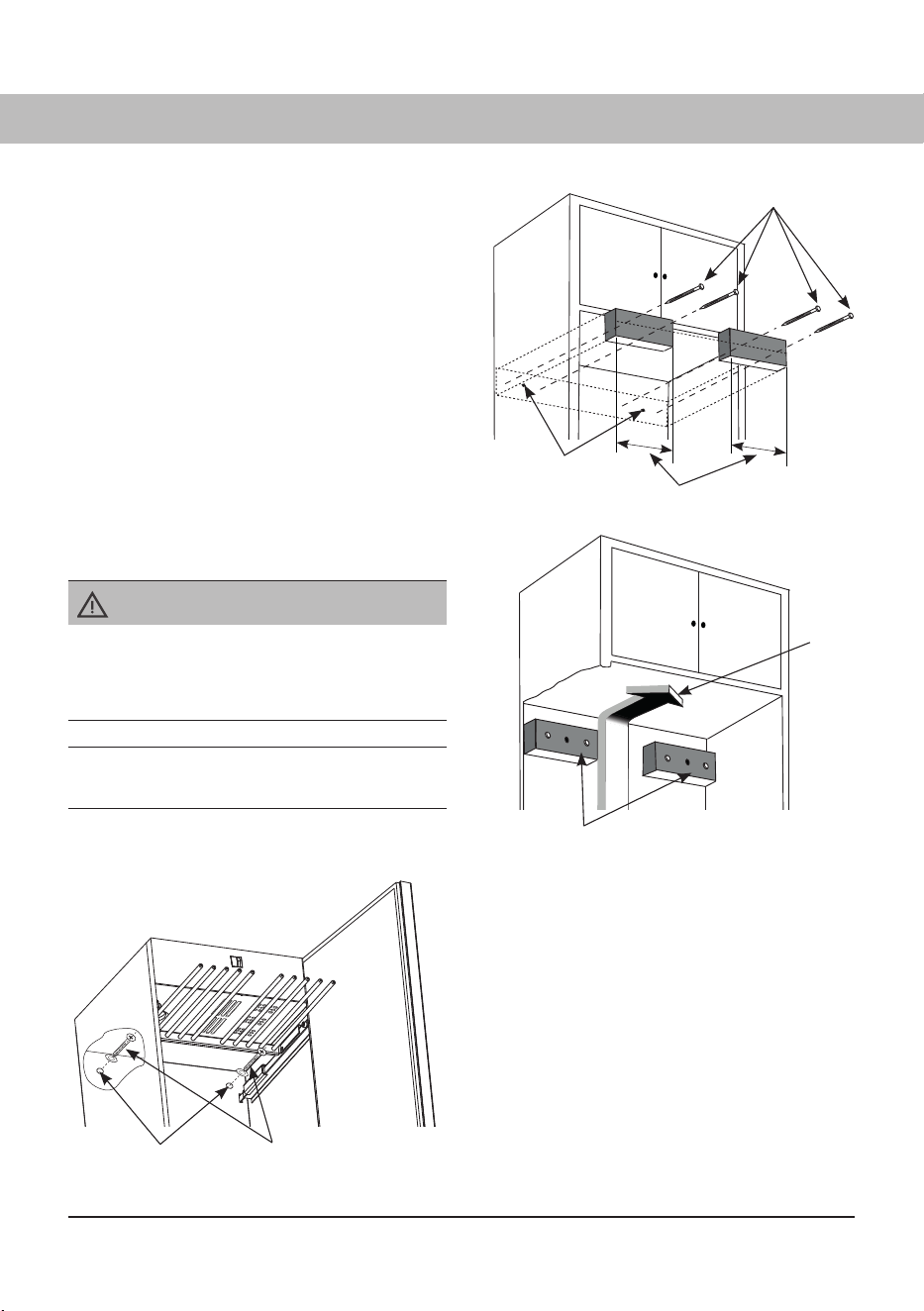
8 Push the drying cabinet back into its fi nal
location. Remove the tape that holds the
door closed and check that the shims
are aligned with the back of the drying
cabinet. Also check that the drying cabinet’s
front section fi ts properly into the custom
cabinetry.
9 Level the drying cabinet according to
section “Levelling”.
10 Pull out the upper hanger section and drill
assembly holes in the wood shims for the
mounting screws through the predrilled
holes in the back of the drying cabinet.
11 Secure the cabinet with the supplied screws
and associated washers.
1. Fastening screws
2. Mounting hole markings from the
predrilled holes in the rear drying
cabinet wall.
3. Air fl ow
4. Wood shims
5. Pre-drilled holes
6. Retaining screws with washers
Custom cabinetry with mounted wood shims
allowing free airfl ow.
IMPORTANT!
Check that the shims are properly secured to
the rear wall and that the installation screws do
not obstruct the drying cabinet’s mounting holes.
The wood shims are not included in the delivery.
879787en.indd 23879787en.indd 23 18. 04. 2024 15:08:0118. 04. 2024 15:08:01
89
1
2
3
4
6
7
5
24
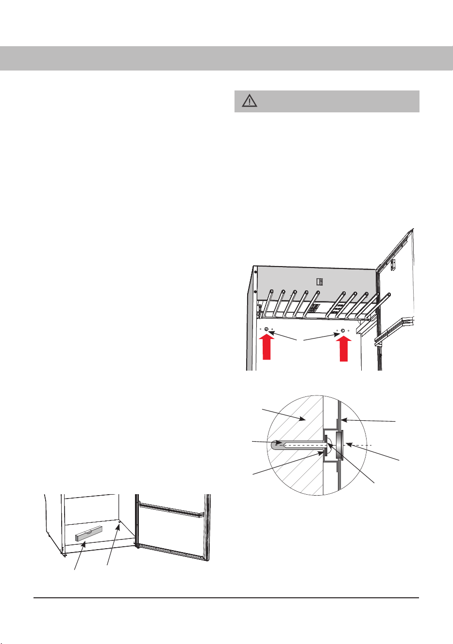
1. Pre-drilled holes
2. Wall plug
3. Wall behind drying cabinet
4. Fixing screws
5. Washer
6. Rear wall of drying cabinet
7. Cover plug
8. Spirit level
9. Cover plug
_______________________________
CAUTION!
The drying cabinet must not be used without
being attached to a wall to avoid the risk of
tipping over forward.
______________________________________
________________________________________
The installation is not complete and the cabinet
must not be used until the drying cabinet has
been attached to the wall according to the
installation instructions. The illustration shows
the attachment points.
_________________________________________
Drying cabinet with extended upper hanger section
______________________________________
The drying cabinet is intended only for use in-
doors in a dry place.
______________________________________
Do not place the drying cabinet in an area where
high-pressure washing is used for cleaning.
________________________________________
To reduce the risk of fi re, this appliance must be
fastened or otherwise secured to an uncovered
concrete fl oor.
______________________________________
LEVELLING
The drying cabinet must be level on a flat
surface, resting on all four feet.
Use the Allen wrench supplied and adjust the feet
through the holes in the baseplate of the drying
cabinet.
Press the four covering plugs firmly into the holes
after adjustment.
SECURING TO WALL
The cabinet must be secured to a wall to prevent
it from tipping over.
1 Open the door, pull out the upper hanging
section and drill 8 mm holes in the wall
through the two pre-drilled holes in the drying
cabinet with extended upper hanger section
rear of the drying cabinet (1).
2
Fit the plastic plugs in the wall (if
necessary
). Fit
the screw with the flat washer as illustrated.
Cover the holes with the cover plugs. Screws for
fixing, washers and plastic plugs are provided in
the assembly kit.
879787en.indd 24879787en.indd 24 18. 04. 2024 15:08:0118. 04. 2024 15:08:01
1
25
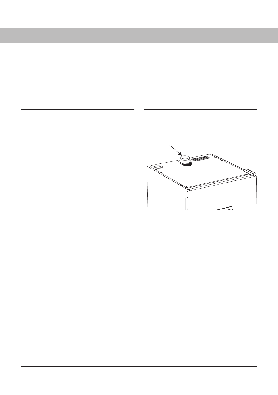
1. Exhaust collar
VENTILATION CONNECTION
If the drying cabinet is installed in a custom
cabinetry, fi t the exhaust collar through the vent
opening in the upper part of the cabinetry when
the drying cabinet is moved to its fi nal location.
The exhaust collar is designed to be screwed in
place with two screws to the drying cabinet’s top
plate. There are predrilled holes in the exhaust
collar and top plate.
1 Place the exhaust collar over the hole in the
drying cabinet’s top plate, align the screw
holes and screw the exhaust collar into
place.
2 Connect the vent pipe if the drying cabinet
is built in, or press the supplied (only certain
markets) fl exible hose into place. See the
section “Ventilation requirements“.
879787en.indd 25879787en.indd 25 18. 04. 2024 15:08:0518. 04. 2024 15:08:05
Minimum 1 ft
(30 cm)
To p
1
2
To p
Minimum 1 ft (30 cm)
1
2
26
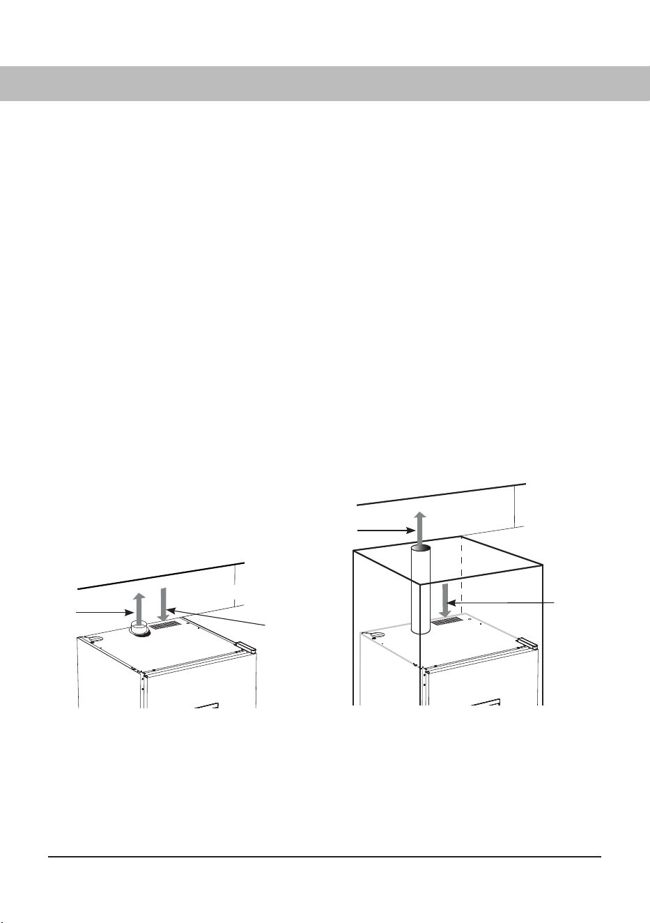
VENTILATION REQUIREMENTS
Moist air can be discharged in two ways:
Ventilation out into the room where the drying cabinet is located
Connection to a vent duct (exhaust air ventilation)
VENTILATION OUT INTO THE ROOM WHERE THE DRYING CABINET IS LOCATED
It is advisable to open a door or window in the room for optimal ventilation.
When the drying cabinet is built in, the supplied vent hose (only certain markets) is replaced by a
solid vent pipe with a diameter of 4 in.(10.2 cm). The vent pipe should not exceed 3 ft (91.4 cm)
in length.
The distance between the vent pipe’s upper edge and the ceiling must not be less than 1 foot
(30 cm).
The vent pipe must extend beyond the enclosing cabinet work.
Provide appropriate air supply to the drying cabinet’s air intake.
Ventilation out into the room where the drying
cabinet is located. Drying cabinet not built in.
Ventilation out into the room where the drying
cabinet is located. Built-in drying cabinet in
custom cabinetry.
1. Moist air out
2. Air intake
879787en.indd 26879787en.indd 26 18. 04. 2024 15:08:0518. 04. 2024 15:08:05
27
EVACUATION / AIR SUPPLY
When the cabinet is on, 15895⁄32 ft
3
(45 m
3
) moist air per hour is evacuated. It must therefore be
ensured that air can enter the room to replace the moist air that is vented out.
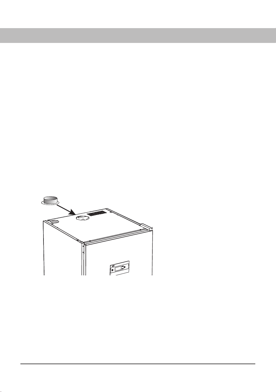
CONNECTION TO EVACUATION
The drying cabinet can be connected to the evacuation duct in two ways, either with a draft
stabilizer or permanently fitted to a mechanical exhaust ventilation unit.
If the drying cabinet is to be connected to an existing ventilation system, a draft stabilizer must always
be used, so that the general ventilation in the room is not aff ected.
Permanent fitting must only be carried out when a separate exhaust-air duct is routed to the drying
cabinet, the air flow in the exhaust-air duct being adjusted to 15895⁄32 ft
3
(45 m
3
) per hour.
The drying cabinet has been tested and factory-set for connection with a draft stabilizer.
Place the supplied spigot over the
hole on the top of the cabinet, insert
the screws and secure the spigot.
879787en.indd 27879787en.indd 27 18. 04. 2024 15:08:0618. 04. 2024 15:08:06
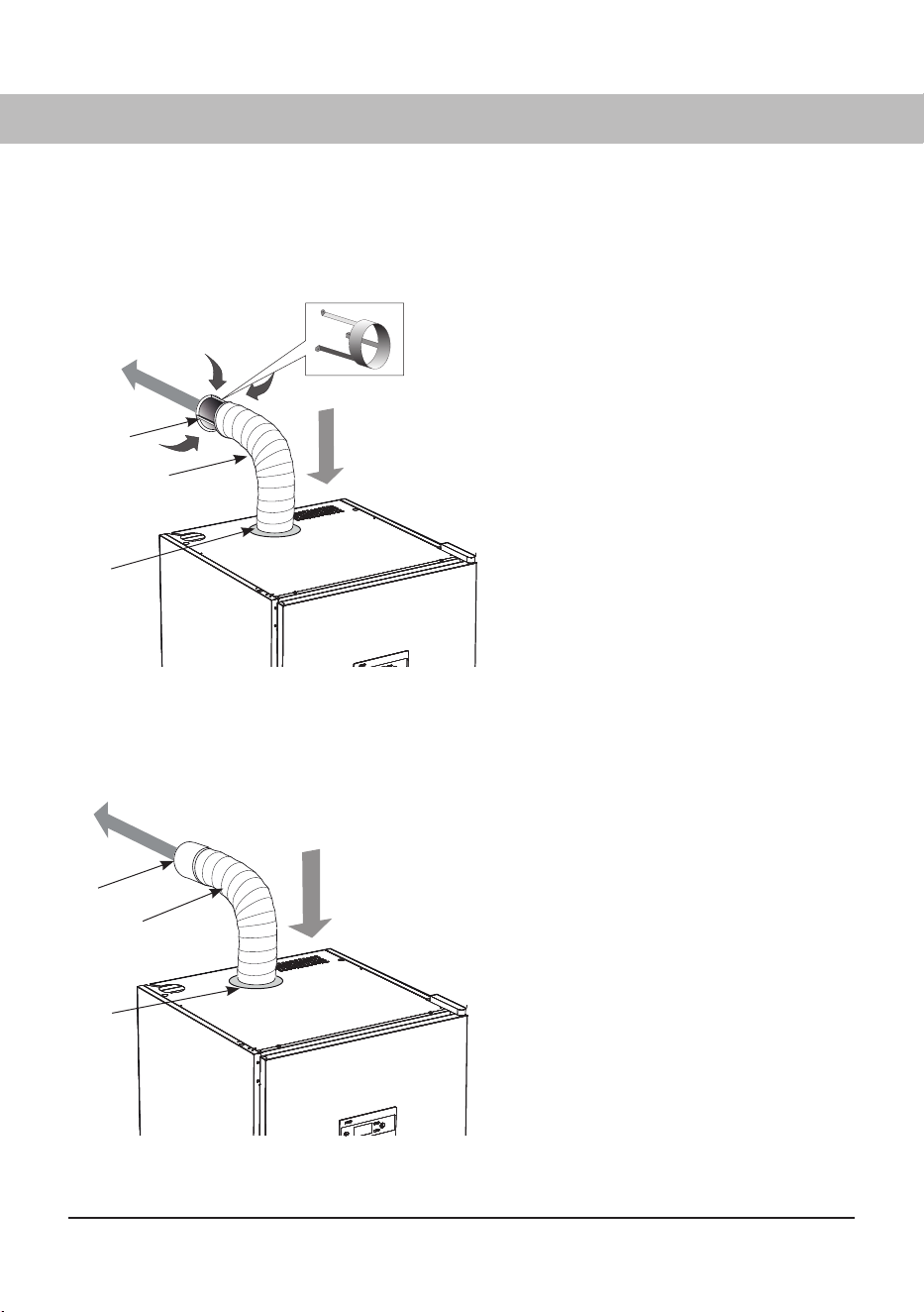
28
PERMANENTLY FITTED TO MECHANICAL EXHAUST AIR VENTILATION UNIT
When the cabinet is permanently con-
nected to a ventilation duct, the whole
room is ventilated through the drying
cabinet.
Connect the hose to the adapter between
the hose and the ventilation duct.
________________________________
The air inlet must not be blocked.
________________________________
Adapter is not supplied.
________________________________
1. Adapter
2. Hose
3. Spigot
1
2
3
Moist air out
Air inlet
3
2
1
Air inlet
Moist air out
WITH DRAFT STABILIZER
Fit the supplied hose onto the spigot. Connect the other end of the hose to the draft stabilizer and then
secure this on the exhaust vent in the room.
________________________________
The drying cabinet must not be connected
to a fl ue.
________________________________
The air inlet must not be blocked.
________________________________
1. Draft stabilizer
2. Flexible hose
3. Spigot
879787en.indd 28879787en.indd 28 18. 04. 2024 15:08:0618. 04. 2024 15:08:06
29
ELECTRICAL CONNECTION
CAUTION!
Read the Electrical Requirements and
Grounding instructions before connecting the
drying cabinet.
The drying cabinet is connected to a 120 V
single-phase 60 Hz and protectively grounded
wall socket.
Fuse 13 A .
The drying cabinet is supplied ready for
connection with a power cord and an grounded
plug.
______________________________________
The drying cabinet should be connected to an
grounded wall socket using the supplied power
cord and must not be permanently wired.
______________________________________
The outlet should be located so that the plug can
be easily pulled out if necessary.
______________________________________
Check that the supply current matches the
data on the rating plate and that the outlet is
grounded correctly according to local code. We
recommend that the power cord be fi tted with a
residual current device (RCD).
______________________________________
The drying cabinet must be connected to a
dedicated circuit.
______________________________________
Do not connect the drying cabinet to the
power supply with an extension cord as the
necessary safety cannot be guaranteed (risk of
overheating).
______________________________________
The appliance's connection to power supply
should comply with the relevant electrical safety
regulations.
______________________________________
______________________________________
The manufacturer disclaims all liability if the
electrical connection has not been carried out
in the way described in this use and care manual.
______________________________________
If the power cord is damaged for any reason, it
must be replaced. Original spare part is available
from the drying cabinet dealer.
A damaged power cord may only be replaced by
a person authorized by the manufacturer.
______________________________________
CAUTION!
A damaged connecting cable may only be
replaced with a special connecting cable of
the same type (can be ordered from ASKO's
spare parts department). For safety reasons,
the replacement may be carried out only by a
qualifi ed electrician or by ASKO Service.
879787en.indd 29879787en.indd 29 18. 04. 2024 15:08:0918. 04. 2024 15:08:09
30
______________________________________
Read this User Manual before
starting the drying cabinet.
______________________________________
BEFORE USING THE DRYING CABINET
CAUTION!
Read the safety instructions (see the chapter
"IMPORTANT SAFETY INFORMATION") before
using the drying cabinet.
Make sure that the cabinet is fi rmly attached
to the wall. See the chapter "PLACEMENT".
Make sure that no packaging material has
been left behind.
Use a mild detergent with hot water and
wash the inside and outside of the drying
cabinet. Dry carefully. See also the ‘Care’
section later in the manual.
879787en.indd 30879787en.indd 30 18. 04. 2024 15:08:0918. 04. 2024 15:08:09

31
WARNING!
To reduce the risk of electric shock or injury
to persons, read the "IMPORTANT SAFETY
INSTRUCTIONS" section before operating this
appliance.
ARRANGING LAUNDRY FOR
DRYING
There are three sections with hangers in the
cabinet. Each section has a number of rails for
hanging laundry.
Hang the items in the drying cabinet
according to how much space they require -
not according to their weight.
For most effi cient drying, do not lay item fl at
on the upper hanger section.
Place long items of clothing closest to
the walls of the cabinet and shorter items
towards the center of the cabinet. The most
effi cient drying results are achieved by
hanging the items in this way.
Fold up the two bottom hanger sections if
long items are to be dried.
Hang gloves, caps, scarves and similar
items on the door hangers/glove hangers on
the inside of the door.
To make it easier, extend the hanger section
when hanging laundry.
Do not overload the drying cabinet. If you
do, the laundry will become creased and dry
unevenly. Instead, leave a space between
the items of clothing if possible.
If there is a risk of particular items shedding
color, free space should be left around them.
Avoid drying heavy items of clothing together
with lighter items as they have very diff erent
drying times.
Do not hang knitted items. These will stretch
unnecessarily as they are heavy when wet.
CABINET EQUIPPED WITH COAT
HANGER RACK AND SHOE RACK
For more effi cient drying, hang shirts,
jackets, etc. on clothes hangers and hang
these on the clothes hanger rack.
Use the shoe rack for more effi cient drying of
shoes.
USER ADVICE
Always following the laundry instructions on
the item of clothing if present.
If a fabric conditioner or anti-static agent is
used, follow the manufacturer's instructions
for use of this product.
Remove laundry that it is already dry. This
will reduce drying time for remaining laundry.
OPERATION
879787en.indd 31879787en.indd 31 18. 04. 2024 15:08:0918. 04. 2024 15:08:09
32
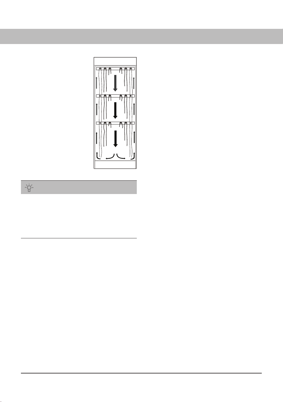
AIR FLOW
The illustration shows
the air fl ow in the drying
cabinet.
Keep the area around
the evacuation duct
clear of dust and dirt.
Make sure that the air
intake and exhaust
duct are not blocked.
NOTE
When the cabinet is cold it may happen that the
sealing strip of the door does not close completely.
However, this is fully compensated when the
cabinet is operating with heat as the sealing strip
expands.
879787en.indd 32879787en.indd 32 18. 04. 2024 15:08:0918. 04. 2024 15:08:09

33
DRYING PROGRAMS
This drying cabinet is equipped with automatic programs and manual drying programs for effi cient
drying of fabrics of diff erent kinds.
The automatic programs automatically switch off the drying process when the fabrics are dry. During
the last 10 minutes, the heat is switched off while the fan cools down the fabrics (cool-down period).
The manually time-controlled programs stop after a set time has been counted down. Cooling also
takes place in the last 10 minutes of drying time in this case.
AUTOMATIC PROGRAMS
Aut 104°F (40°C) Normal dry. Used for drying items of normal thickness.
Aut 104°F (40°C) Extra dry. Used for drying thicker items, deep drying.
Aut 140°F (60°C) Normal dry. Used for drying items of normal thickness.
Aut 140°F (60°C) Extra dry. Used for drying thicker items, deep drying.
104°F (40°C) or 140°F (60°C) is selected taking account of the washing instructions for the item.
MANUAL PROGRAMS
Man 86°F (30°C). A time-controlled drying program that should be selected for sensitive fabrics
that should not be exposed to temperatures above 86°F (30°C).
Man 104°F (40°C). As above, but a somewhat higher drying temperature is allowed.
Man 140°F (60°C). As above, but the fabrics can be dried at max. 140°F (60°C).
Man --. This is a very energy-effi cient drying program without heat, only the fan dries the laundry.
86°F (30°C), 104°F (40°C) or 140°F (60°C) is selected taking account of the washing instructions for
the item.
NOTE
It is very important to follow the laundry
instructions for the fabrics concerned when
selecting the drying program.
879787en.indd 33879787en.indd 33 18. 04. 2024 15:08:1018. 04. 2024 15:08:10

34
CHILD LOCK
To make sure that the drying process is not interrupted or started by mistake, a child lock function can
be activated.
FUNCTION OF THE CHILD LOCK
Activation buttons must be held down for a least 3 seconds (delay time).
ACTIVATION/DEACTIVATION OF CHILD LOCK
The child lock is activated and deactivated via a setting parameter (see the chapter "SETTING
DRYING PROGRAMS/Parameter list"). When this function is activated, a clock symbol appears on the
display.
879787en.indd 34879787en.indd 34 18. 04. 2024 15:08:1018. 04. 2024 15:08:10

35
START AUTOMATIC PROGRAM
Start the cabinet by pressing ON/OFF.
The display lights up and shows the last program used.
E.g.
AUT 104° NormaL DRY The text flashes.
If this is OK - press OK and the process will then start.
– or select another program with UP / DOWN ARROW +
OK and the process will then start.
STARTING A MANUAL PROGRAM
Start the cabinet by pressing ON/OFF.
The display lights up and shows the last program used
e.g. MAN 104° The text flashes.
If this is OK - press OK the default or last used drying time flashes,
e.g.
2:30 (two hours, 30 minutes)
If this is OK - press OK the process starts at once, in this example, Man 104°F (40°C)
program where the time is counted down from 2½ hours.
– or select a diff erent drying time with UP ARROW (increases
drying time) DOWN ARROW (reduces drying time) + OK the
process starts with a Man 104°F (40°C) program with a new
drying time.
A diff erent manual drying program is selected in the same way as above.
If the child lock is activated, hold this button down for at least 3 seconds.
FACTORY-SET DRYING TIMES FOR MANUAL PROGRAMS
Man 86°F (30°C) 2:30 (two hours, 30 minutes)
Man 104°F (40°C) 2:30
Man 140°F (60°C) 2:30
879787en.indd 35879787en.indd 35 18. 04. 2024 15:08:1018. 04. 2024 15:08:10

36
USER ADVICE
If you have made a mistake or are unsure where you are, you can always press ON/OFF and start
selecting drying program again.
If the door is open when a drying program is started and the OK button is activated, the display
will show “close door”. Close the door, and the selected drying program will start.
The animated symbol (bar) on the left side of the display indicates that the drying process is in
progress.
When the drying process has finished, the display shows the text “end” (flashing). When the STOP
button is then pressed, or the door is opened, the current program ends and the display shows
the last used program.
NOTE: In standby mode the display goes off after 15 minutes and lights up when any of
the buttons on the control panel is activated or the door is opened.
To halt a drying process in progress, press STOP.
If the door is opened while the drying process is in progress, the fan will continue operating for
another 5 minutes. The display shows “close door” and counts down the 5 minute program pause
period.
If the door is closed within this 5 minute period, the drying process will restart.
If the door is left open, the drying process will stop after 5 minutes and must be restarted
manually.
If you wish to stop the drying process immediately, without a 5 minute period, press STOP.
879787en.indd 36879787en.indd 36 18. 04. 2024 15:08:1018. 04. 2024 15:08:10

37
Setting to optimise the drying cabinet's automatic program is done using the buttons on the control
panel when the drying cabinet is in programming mode.
Adjustments must be made if it is found that
the laundry does not dry sufficiently.
the laundry is over-dried – long drying time.
PROGRAMMING MODE
1 Make sure that the ON/OFF switch on the drying cabinet is in the OFF position. The display is
unlit.
2 Hold down the UP ARROW and DOWN ARROW buttons simultaneously and press the
ON/OFF switch to the “ON” position. The display is lit and shows “P 105” flashing, which is the first
setting parameter in the list below. Then select the relevant parameter using the arrow keys and
confirm with OK.
3 To return to operating mode, press DOWN ARROW and then OK.
SETTING DRYING PROGRAMS
879787en.indd 37879787en.indd 37 18. 04. 2024 15:08:1018. 04. 2024 15:08:10
38
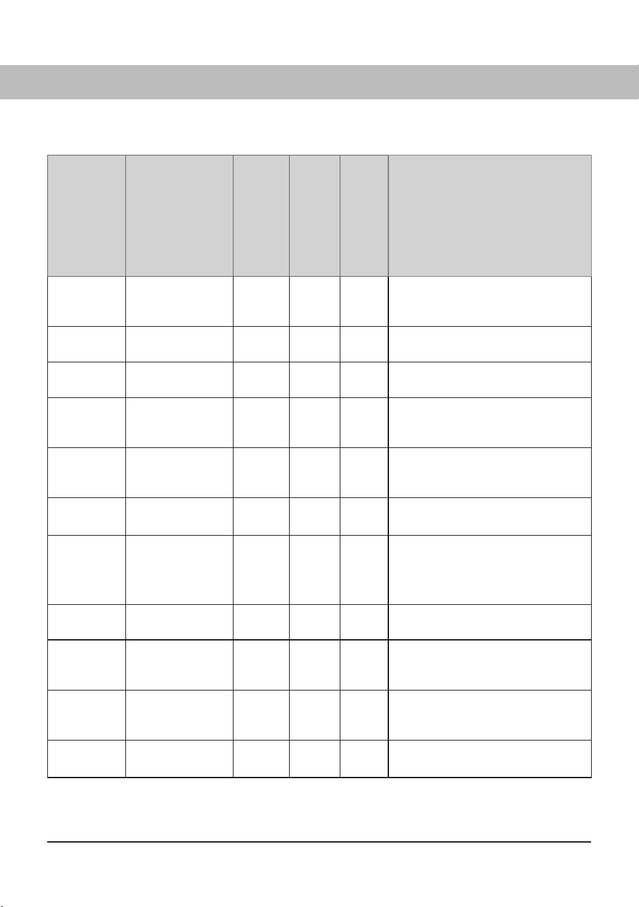
PARAMETER LIST
Parameter
Name
Factory preset
Min value
Max value
Signifies
P105 Language 1 0 7 Swedish
For setting, see the chapter
"COMPONENTS/Language".
P106 Temperature
system
1 0 1 Signifi es: 1 = Fahrenheit, 0 = Celsius
P115 Child lock On/Off 001Off .
Value 1 = Child lock ON
P2011 Min drying time
Aut 104°F (40°C)
35 min 10 min 45 min Regardless of moisture level, the
drying process runs 35 min.
Factory preset.
P2012 Max drying time
Aut 104°F (40°C)
360 min 60 min 360 min Regardless of moisture level, the
drying process runs 360 min.
Factory preset.
P2013 Max temp
Aut 104°F (40°C)
123°F
(51°C)
106°F
(41°C)
142°F
(61°C)
The heating elements switch off if the
value is exceeded.
P2014 Exhaust temp.
process fi nished
Aut 104°F (40°C)
95°F
(35°C)
93°F
(34°C)
129°F
(54°C)
For Normal programs the drying
process ends with cooling.
For Extra programs the extra drying
time starts, followed by cooling.
P2015
Extra drying time
Aut 104°F (40°C)
30 min 10 min 45 min Extra program drying time after
exhaust temp. has been reached.
P2021 Min drying time
Aut 140°F (60°C)
35 min 15 min 45 min Regardless of moisture level, drying
process runs 35 min.
Factory preset.
P2022 Max drying time
Aut 140°F (60°C)
240 min 60 min 360 min Regardless of moisture level, drying
process runs 240 min.
Factory preset.
P2023 Max temp
Aut 140°F (60°C)
194°F
(90°C)
142°F
(61°C)
212°F
(100°C)
The heating elements switch off if the
value is exceeded.
879787en.indd 38879787en.indd 38 18. 04. 2024 15:08:1018. 04. 2024 15:08:10
39
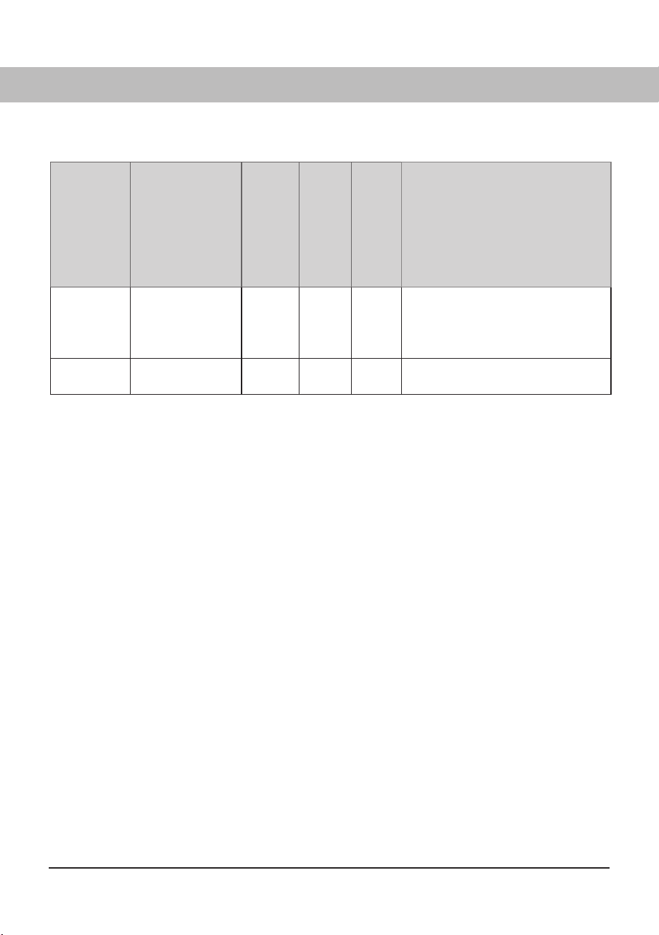
Parameter
Name
Factory preset
Min value
Max value
Signifies
P2024 Outlet temp.
process fi nished
Aut 140°F (60°C)
107°F
(42°C)
104°F
(40°C)
163°F
(73°C)
For Normal programs the drying
process ends with cooling.
For Extra programs the extra drying
time starts, followed by cooling.
P2025
Extra drying time
Aut 140°F (60°C)
30 min 10 min 45 min Extra program drying time after
exhaust temp. has been reached.
879787en.indd 39879787en.indd 39 18. 04. 2024 15:08:1018. 04. 2024 15:08:10

40
ADJUSTMENT
The program Aut 104°F (40°C) Normal is controlled via temp sensor exhaust air.
The program Aut 104°F (40°C) Extra is controlled via temp sensor exhaust air and a time factor.
The program Aut 140°F (60°C) Normal is controlled via temp sensor exhaust air.
The program Aut 140°F (60°C) Extra is controlled via temp sensor exhaust air and a time factor.
The automatic programs end automatically when the laundry is dry.
To decide when the laundry is dry, the actual exhaust air temperature is compared against a
parameter, P2014 for 104°F (40°C) program and P2024 for 140°F (60°C) program.
For Aut 104°F (40°C) Extra an extra drying time is additionally added according to parameter P2015.
For Aut 140°F (60°C) Extra an extra drying time is additionally added according to parameter P2025.
It is primarily these four parameters that are adjusted to optimise the drying processes of the
automatic programs.
Aut 104°F (40°C) Normal and Aut 104°F (40°C) Extra are adjusted with parameter P2014.
Aut 104°F (40°C) Extra is additionally adjusted with parameter P2015 (extra drying time).
Aut 140°F (60°C) Normal and Aut 140°F (60°C) Extra is adjusted with parameter P2024.
Aut 140°F (60°C) Extra is additionally adjusted with parameter P2025 (extra drying time).
If it is found that the laundry does not dry suffi ciently, the parameter value is increased.
If it is found that the laundry is over-dried, long drying time, the parameter value is reduced.
Optimisation of drying processes must always take place in small steps, start by adjusting the
parameter concerned one to two units up or down. Then check the result after the next drying process
and make any further adjustment necessary.
879787en.indd 40879787en.indd 40 18. 04. 2024 15:08:1018. 04. 2024 15:08:10

41
PROCEDURE
The setting parameters according to the list
(see the chapter "SETTING DRYING PROGRAMS/
Parameter list")
are shown on the display as follows:
on the top row of the display the relevant parameter is shown, for example P 2014,
on the bottom row the set value of the parameter is shown.
1 Go to programming mode.
See the chapter "SETTING DRYING PROGRAMS/Programming
mode".
2 Browse to the relevant parameter by pressing the ARROW UP or ARROW DOWN key repeatedly. If
you go too far, simply continue browsing until the display shows the correct parameter.
3 When the display shows the correct parameter, for example ”P 2012”, press OK to confirm. The row
now flashes with the set value of the parameter.
4 Increase or reduce the value using the ARROW UP or ARROW DOWN key.
5 To save the set value, press OK.
6 To return to operating mode, press DOWN ARROW and then STOP.
RESTORING TO FACTORY SETTING
1 Go to programming mode (
see the chapter "SETTING DRYING PROGRAMS/Programming
mode")
.
2 Hold down the UP ARROW and DOWN ARROW keys simultaneously and press OK.
The factory settings are saved and the display shows the last run program.
879787en.indd 41879787en.indd 41 18. 04. 2024 15:08:1018. 04. 2024 15:08:10
42
CLEANING
NOTE
Do not use high-pressure cleaning.
Clean the walls of the cabinet with a mild
soap solution on a damp cloth.
Dust tends to collect around the air intake
on the top of the cabinet. This can cause
disruption, in turn leading to breakdowns in
operation.
To avoid these problems, the air intake and
the roof of the cabinet should be vacuumed
at least once a year, or more often
depending on the environment the cabinet
is positioned in.
CARE
REPLACEMENT PART
If the power cord for any reason is damaged, it must
be replaced. A genuine spare part can be obtained
from the dealer who supplied the cabinet.
NOTE
A replacement cord may be installed only by the
manufacturer, the manufacturer’s service agent
or other qualifi ed electrician.
NOTE
Cleaning and maintenance must not be
performed by children without supervision.
879787en.indd 42879787en.indd 42 18. 04. 2024 15:08:1018. 04. 2024 15:08:10
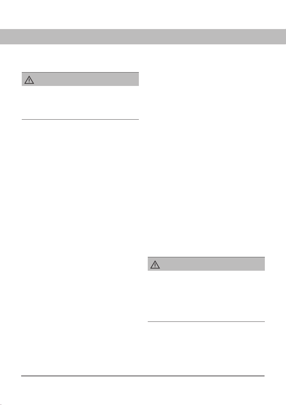
43
The cabinet is equipped with an overheat cut-
out.
This trips when the temperature in the fan unit
exceeds 248°F (120°C).
When the overheat cut-out triggers, the display
dims down and pauses the ongoing program.
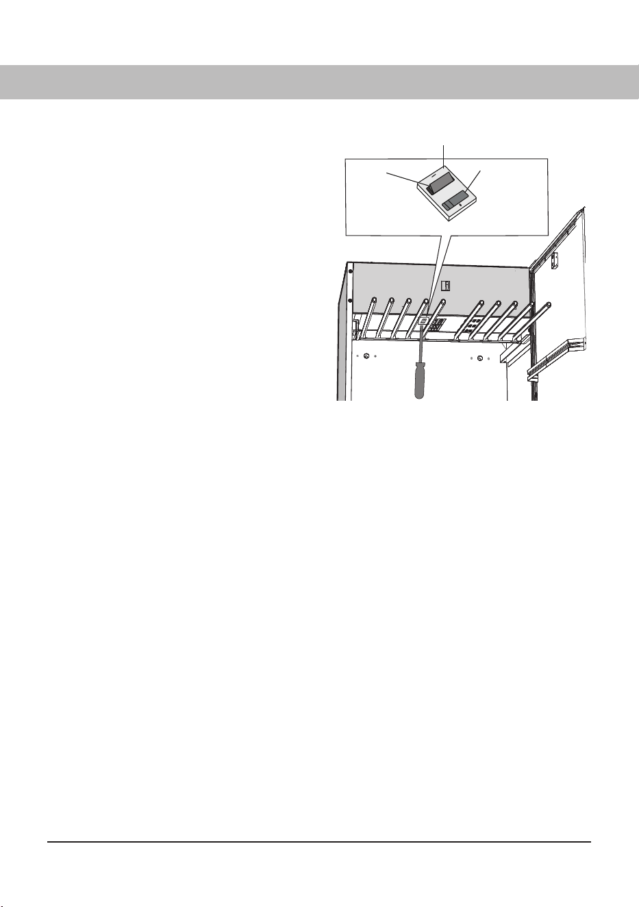
1 You reset the overheat cut-out by turning OFF
the power supply with the switch inside the
roof of the cabinet. See illustration.
2 You must then wait 15 to 20 minutes before
the temperature has fallen.
3 Now you can reset the overheat cut-out by
turning ON the power supply with the switch
inside the roof of the cabinet. See illustration.
If the overheat cut-out triggers again when you
start a program, redo step 1, 2, 3 above.
If overheat cut-out triggers several times, call for
service.
OVERHEAT CUT-OUT
Hole in inner panel for operation of the toggle
switch with a screwdriver or similar tool.
OFF
press the
switch in the
rear hole
Toggle switch behind inner panel.
ON
press the
switch in the
front hole
879787en.indd 43879787en.indd 43 18. 04. 2024 15:08:1118. 04. 2024 15:08:11
44
TROUBLESHOOTING
DEAL WITH MINOR FAULTS YOURSELF
Problem What you can do
The drying cabinet is not
working
1. Check that the power cord is connected to a outlet.
2. Check that no breaker has tripped.
3. Have you pressed the start button?
4. Is the door closed?
The display shows an alarm/
error code
This should normally not happen, but if an alarm or error code
appears, fi rst try to reset the alarm by holding the START/STOP
button down for 5 sec. If the problem persists, a service technician
must be called in.
Drying takes a long time
1. Check that the correct program has been selected for the type of
laundry.
2. Check that the laundry is not very wet (poorly spun).
3. Check that too much laundry has not been hung.
The washing does not
become dry
1. Check that the correct program has been selected for the type
of laundry.
2. Check that too much laundry has not been hung.
3. Adjust parameters 2014, 2015, 2024 and 2025 according to the
chapter “Setting of drying program”.
The sealing strip does not
close tightly/the door is ajar
Check that the cabinet is level. Check with a spirit level, if
necessary adjust with the adjustable feet.
879787en.indd 44879787en.indd 44 18. 04. 2024 15:08:1218. 04. 2024 15:08:12

45
SERVICE AND WARRANTY
LIMITED WARRANTY – RESIDENTIAL APPLIANCES
This Limited Warranty covers parts and labor, except as set forth in this Limited Warranty. Service
must be provided by an authorized ASKO service company. YOUR SOLE AND EXCLUSIVE REMEDY
UNDER THIS LIMITED WARRANTY SHALL BE PRODUCT REPAIR AS PROVIDED HEREIN. This
Limited Warranty is valid only when the ASKO Product is used in the country in which it was pur-
chased. Proof of original purchase date is required to obtain service under this Limited Warranty.
This warranty only applies to the original purchaser and is non-transferable.
Residential ASKO Products Used Exclusively for Household/Personal Purposes:
Two (2) Years limited Warranty – Any warranty service claims for residential ASKO Products must be
fi led with ASKO within two (2) years from date of purchase. Service will be provided during normal
business hours.
Residential ASKO Products Not Used Exclusively for Household/Personal Purposes or used
Commercially or used in Marine, Mobile or Aeronautical Applications:
One (1) Year limited Warranty – Any warranty service claims for ASKO Products not used exclusively
for household and personal use, or used commercially or used in marine, mobile, or aeronautical
applications must be fi led with ASKO within one (1) year from date of purchase. Service will be
provided during normal business hours.
ITEMS EXCLUDED FROM WARRANTY
This limited warranty does not cover:
1. Replacement parts or repair labor if the ASKO Product is used in a manner that is inconsistent with
published user or operator instructions and/or installation instructions.
2. Service calls to correct the installation of the ASKO Product, to instruct you on how to use the ASKO
Product, to replace or repair house fuses, or to correct house wiring or plumbing.
3. Consumable items and parts, such as fi lters.
4. Damage resulting from accident, alteration, misuse, abuse, negligence, fi re, fl ood, acts of God,
improper use, improper installation, installation not in accordance with electrical or plumbing codes,
or use of products not approved by ASKO, as well as any attempted repair by other than authorized
ASKO service companies.
5. Cosmetic damage, including scratches, dents, chips or other damage to the fi nish of the ASKO
Product, unless such damage results from defects in materials or workmanship and is reported to
ASKO within 5 days from date of purchase.
6. Pickup and delivery. The ASKO Product is intended to be repaired in your home.
7. Repairs to parts or systems resulting from unauthorized modifi cations made to the ASKO Product.
8. Expenses for travel and transportation for product service if the ASKO Product is located in a remote
area where service by an authorized ASKO service company is not available.
9. The removal and reinstallation of the ASKO Product if it is installed in an inaccessible location or is
not installed in accordance with ASKO’s published installation instructions.
10. Replacement parts or repair labor on ASKO Products with original model/serial numbers that have
been removed, altered or cannot be easily determined.
879787en.indd 45879787en.indd 45 18. 04. 2024 15:08:1218. 04. 2024 15:08:12

46
DISCLAIMER
YOUR SOLE AND EXCLUSIVE REMEDY UNDER THIS LIMITED WARRANTY SHALL BE PRODUCT
REPAIR AS PROVIDED HEREIN. EXPRESSLY DISCLAIMED ARE ALL OTHER EXPRESS AND
IMPLIED WARRANTIES, INCLUDING ANY IMPLIED WARRANTIES OF MERCHANTABILITY AND
FITNESS FOR A PARTICULAR PURPOSE. Some jurisdictions do not allow exclusion or limitations
regarding warranty rights. This Limited Warranty gives you specifi c legal rights and you may have
other rights that vary from jurisdiction to jurisdiction. Attempted repair by any person other than an
authorized ASKO service company will void this Limited Warranty.
Limitation of liability
IN NO EVENT SHALL ASKO OR THE MANUFACTURER AND THEIR RESPECTIVE PARENTS, SUB-
SIDIARIES AND AFFILIATES BE LIABLE FOR CONSEQUENTIAL, INCIDENTAL, EXEMPLARY,
PUNITIVE OR SPECIAL DAMAGES. IN NO EVENT SHALL ASKO OR THE MANUFACTURER AND
THEIR RESPECTIVE PARENTS, SUBSIDIARIES AND AFFILIATES BE LIABLE FOR DAMAGES
OTHER THAN ACTUAL DAMAGES AND IN NO EVENT FOR DAMAGES IN EXCESS OF THE PRICE
PAID FOR THE ASKO PRODUCT AS TO WHICH A CLAIM IS MADE. Some jurisdictions do not allow
the exclusion or limitation of incidental, consequential or other damages, so these limitations and
exclusions may not apply to you. This Limited Warranty gives you specifi c legal rights. You also may
have other rights that vary from jurisdiction to jurisdiction.
ASKO CUSTOMER CARE
Read the chapter Troubleshooting before contacting the service department. If you have encountered
a problem that you cannot resolve, please contact your nearest dealer.
USA us.asko.com, +1-800-898-1879
CANADA ca.asko.com, +1-800-361-0799, [email protected]
MEXICO asko.com/mx, +52-800-400-4372, atencionalcliente@sub-zeromx.com
When making contact, provide the details on the serial number plate. Include the service number (1),
the article number (2), and the serial number (3).
SERVICE AFTER EXPIRATION OF LIMITED WARRANTY
For information about obtaining parts and labor after expiration of this Limited Warranty or arising
outside the scope of this Limited Warranty, please contact ASKO Customer Care.
879787en.indd 46879787en.indd 46 18. 04. 2024 15:08:1218. 04. 2024 15:08:12
DC 7784V
47
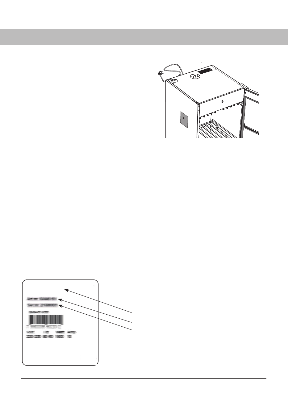
SERVICE
Before contacting Service, you should find out
the name, article number and serial number of
the drying cabinet.
This information can be found on the drying
cabinet located upper left side wall inside the
cabinet.
Service after expiration of limited warranty
For information about obtaining parts and labor
after expiration of this Limited Warranty after or
outside of expiration of this Limited Warranty,
please contact ASKO Customer Care.
Identifi cation plate (inside)
Identifi cation plate for drying cabinet model DC7784V
Name of the drying cabinet
Article number
Serial number (12 digits)
879787en.indd 47879787en.indd 47 18. 04. 2024 15:08:1218. 04. 2024 15:08:12
48
TECHNICAL DATA
MANUFACTURING STANDARD
See cabinet rating plate.
WIRING DIAGRAM
Wiring diagram can be ordered
from the manu- facturer.
IDENTIFICATION PLATE
See the chapter "SERVICE AND
WARRANTY/Service").
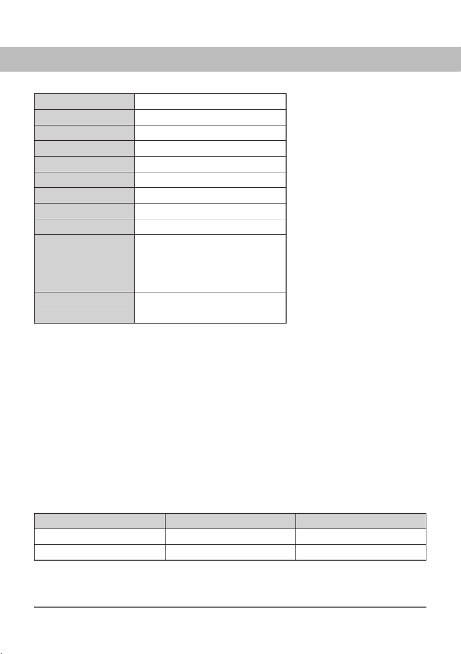
Capacity: 8.82 lbs (4 kg) of laundry (cotton)
Dewatering capacity: 0.59 oz/min (17 g/min)
Electrical supply: Single phase 120 V, 60 Hz
Fuse: 13 A
Motor: 35 W
Heating element: 1300 W
Overheat cut-out: Ye s
Fan capacity: 635641⁄64 ft
3
/hour (180 m³/hour)
Hanging length: 52½ ft (16 metres)
Dimensions
DC7784V:
Height 727⁄16" (1840 mm)
731⁄16" (1855 mm) incl. hinge
Width 237⁄16" (595 mm)
Depth 23⅞ " (606 mm)
25" (635 mm) incl. door handle
Weight of DC7784V: ~138.9 lbs (63 kg)
Sound lavel: max 60 dB(A)
ENERGY CONSUMPTION AND DRYING TIMES
Drying of spun laundry *)
Program Energy consumption Drying time
Aut 104°F (40°C) 0.60 kWh/kg laundry 2 hours 45 min
Aut 140°F (60°C) 0.62 kWh/kg laundry 2 hours
*) Stated values apply to drying cabinet connected with draft stabilizer. Values may vary depending on
spin speed
879787en.indd 48879787en.indd 48 18. 04. 2024 15:08:1318. 04. 2024 15:08:13
ASKO DC 7784V
ae (04-24)
US.ASKO.COM • CA.ASKO.COM • ASKO.COM/MX
Right to make changes reserved.
879787en.indd 52879787en.indd 52 18. 04. 2024 15:08:1318. 04. 2024 15:08:13