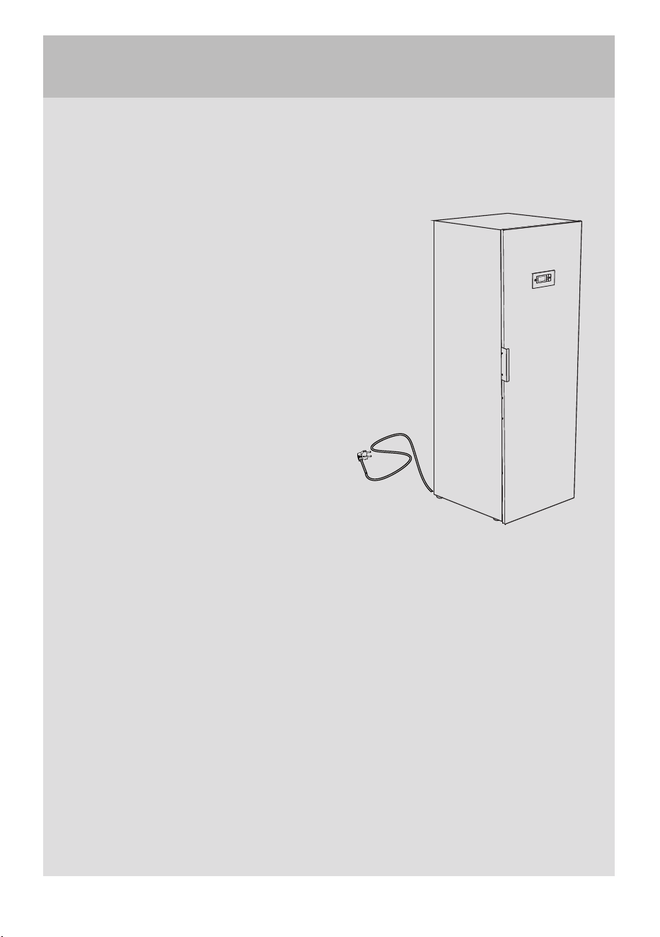
Drying cabinet
DC7784HP.S.UK
USER MANUAL
Read the user manual before using the machine

Dear ASKO customer,
Congratulations on making an excellent choice, and welcome to the ASKO
family, a global family with its roots in Sweden.
We at ASKO thank you for your trust and hope that you will enjoy using
your new drying cabinet.
A good drying cabinet should be well designed, dry clothes well, have a low
environmental impact, be user-friendly, save time and energy, have a long service life and
be reliable. ASKO offers you all these features.
When you buy an ASKO product you can be sure that the inside is just as
good as the outside and that the ethics and morality that go into building this
product are just as high as the quality and function you are getting. That's what Swedish
quality is all about.
Before using the product for the fi rst time, please read the user instructions and the advice
on caring for the product. This will help you get the best possible results from your product
and all its functions.
If you have any questions, do not hesitate to call us or to contact us through
our website.
Best wishes from Sweden and the ASKO team.
3
CONTENTS
THIS USER MANUAL 4
IMPORTANT SAFETY INFORMATION 5
FOR A GOOD ENVIRONMENT 6
Packaging materials 6
Management of end-of-life drying
cabinet 6
DESCRIPTION OF THE DRYING CABINET 7
Air fl ow in the cabinet 8
CONTROL PANEL 9
Function of the button 9
Display 9
Language setting 10
PLACEMENT 11
UNPACKING 12
Assembly kit 12
REHANGING OF DOOR 13
CONDENSATION WATER 17
Detachable water tank 17
Connection to fl oor drain 18
Reconnection to water tank 19
INSTALLATION 20
Positioning/Attachment 20
Electrical connection 21
START-UP 22
OPERATION 23
User tips 24
Drying programmes 25
Selection of drying programme 25
Child lock 25
Starting drying programme 26
Ending drying programme 27
Door opened 27
SETTING OF DRYING PROGRAMME 28
Introduction 28
Procedure 29
Return to operating mode 29
Parameter list 30
Restoring to factory setting 30
CARE 31
Cleaning 31
Service 32
TROUBLESHOOTING 33
LIST OF ERROR CODES 35
TECHNICAL DATA 36

4
The contents of this user manual describe
function, operation and optimisation of
drying programmes, as well as instructions
for installation and maintenance.
Alongside the User Manual there is a Service
Manual.
THIS USER MANUAL
5
IMPORTANT SAFETY INFORMATION
Applicable to installation in the EU
The drying cabinet can be used by children over the age of
8 and persons (including children) with various disabilities or
inadequate experience and knowledge, provided they are kept
under supervision or are given instructions on how to use the
appliance in a safe way and understand the risks that use entails.
Children must not play with the appliance.
Applicable to installation in countries outside the EU
The appliance is not intended for use by persons (including children)
with various disabilities or inadequate experience and knowledge.
They may use the appliance only under supervision or if they have
received instructions on how to use the appliance form a person
who is responsible for their safety.
Children must be supervised to ensure that they do not play with the
appliance.
Applicable to all installation
The drying cabinet must be installed and kept indoors.
If the power cord is damaged, it must be immediately
replaced, and this must be done only by the manufacturer, the
manufacturer's service agent or similarly qualifi ed persons in order
to prevent danger.
Follow ASKO instructions in repair and replacement of parts.
This drying cabinet meets applicable safety requirements. Incorrect use
may, however, lead to injuries and damage to objects.
The advice and caution notices in this manual have been written to enable
you to avoid incorrect use and unnecessary risks of accidents, and should
be read before installing and using the drying cabinet.
CAUTION: This equipment is intended only to be used to dry fabrics
washed in water.
6
FOR A GOOD ENVIRONMENT
PACKAGING MATERIALS
The packaging that protects the drying cabinet
against damage in transit has been chosen
with concern for the environment in mind and is
therefore recyclable.
Packaging that is returned to the material cycle
means reduced consumption of raw materials
and a smaller volume of waste.
MANAGEMENT OF END-OF-
LIFE DRYING CABINET
When the drying cabinet has reached the end
of its useful life, it must be taken to a recycling
centre for disposal. Many parts of the drying
cabinet can be re-used, but it also contains
other materials that must be handled correctly.
You should therefore never leave the drying
cabinet or parts of the cabinet for collection
with household waste, as this may lead to
risks to health and cause damage to the
environment.
The end-of-life drying cabinet should instead
be taken to a recycling centre. Check with your
dealer if necessary.
All the plastic parts of the drying cabinet are
marked with internationally standardised
symbols. The parts of the drying cabinet can
therefore be recycled in an environmentally
sound manner by waste separation.
7
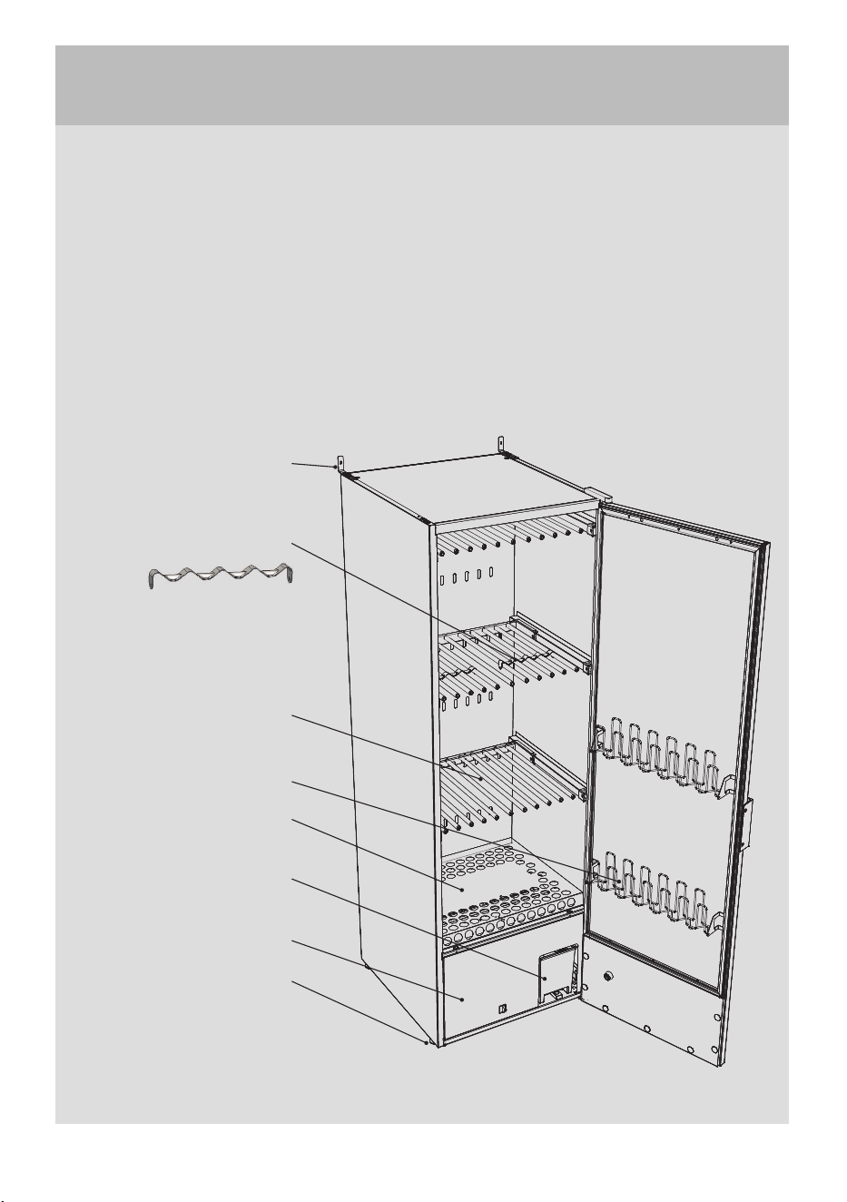
DESCRIPTION OF THE DRYING CABINET
The ASKO DC7784HP drying cabinet operate
according to the heat pump principle with a
dehumidifi er instead of a conventional hot-
air unit. As a result, the washing is dried at
lower heat and with substantially lower energy
consumption.
The cabinet is a completely enclosed system.
No exhaust-air connection is required. The
moisture condenses during the process,
and the water that is formed is conveyed to a
detachable water tank, or through a hose to the
drain.
In addition, the fan is so powerful that it causes
the items of clothing to fl utter, making the drying
process even more effi cient.
Extendible hanger
sections (3x)
Door hangers
Detachable shoe rack
Tank for condensation
water
Dehumidifi er
Adjustable feet (4x)
Wall mount
Clothes hanger rack (2x)
8
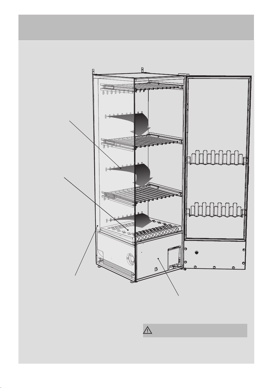
AIR FLOW IN THE CABINET
Air return after dehumidifi cation
Enters a duct in the back of the
drying cabinet
Air intake in 6
rows of holes
Cleaning fi lter
below the shoe
rack
Dehumidifi er
_____________________________
NB
Make sure that shoes and similar items do
not block the airfl ow.
____________________________________
9
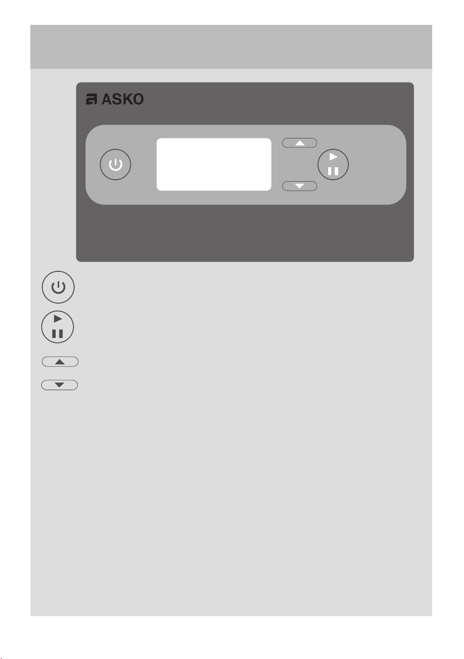
ON / OFF
OK/START/STOP
UP ARROW
DOWN ARROW
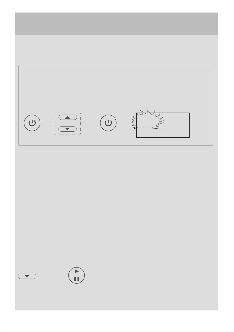
FUNCTION OF THE BUTTON
ON-OFF
The display is lit and shows the last programme used
OK/START/STOP
Confi rms selection of programme, functions and settings.
If the setting fl ashes, it must be confi rmed or changed using the ARROW keys and/or OK. The
drying process starts.
UP ARROW / DOWN ARROW
These are navigation keys to step through lists and information texts.
If UP and DOWN are pressed simultaneously when ON-OFF is turned off ,
PROGRAMMING MODE opens when ON-OFF is pressed.
To return to operating mode, press DOWN ARROW and then OK.
CONTROL PANEL
DISPLAY
The display has two rows with 6 characters
on each row. During the drying process
the selected drying programme and a
rolling bar indicating that the process is in
progress are shown.
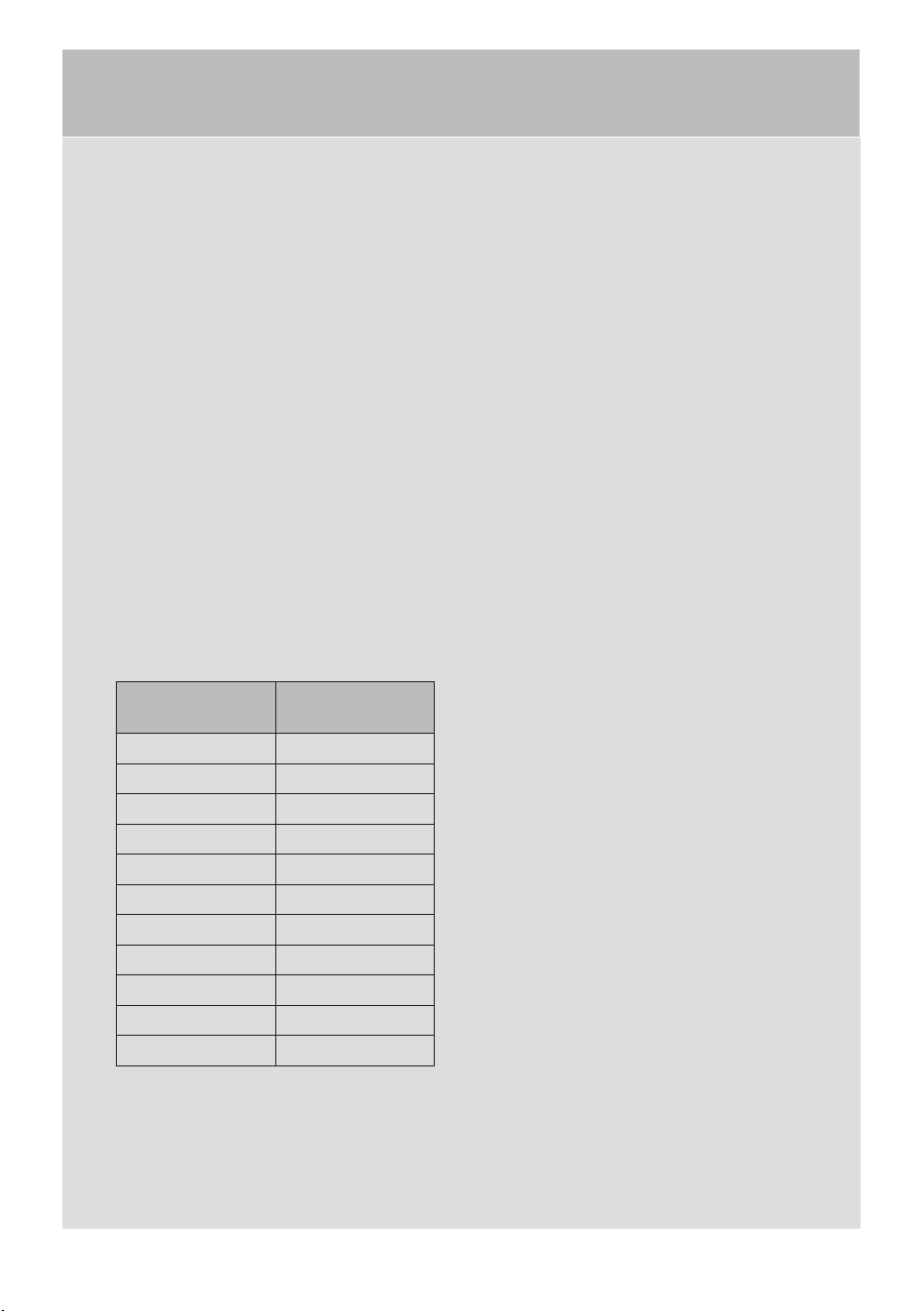
10
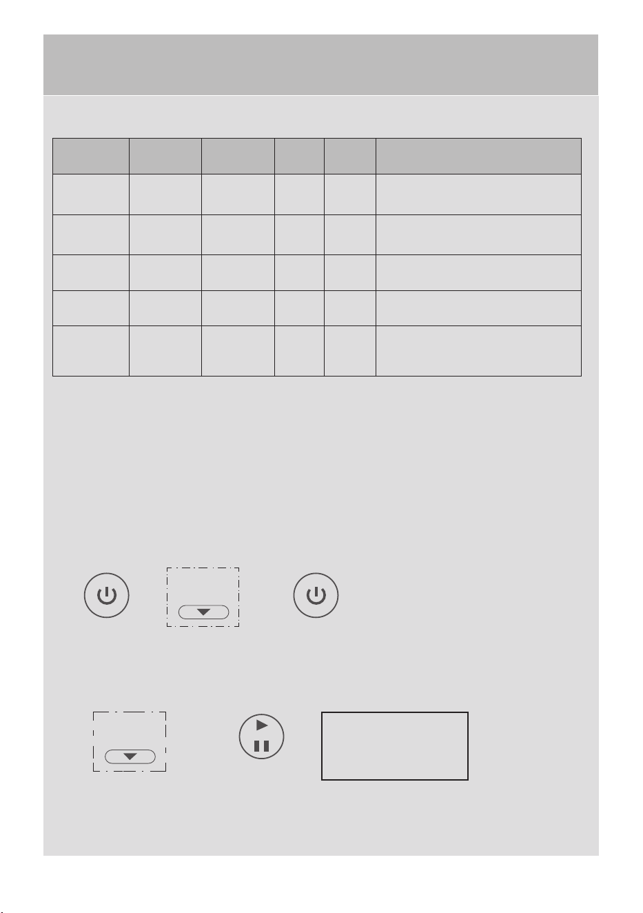
CONTROL PANEL
1 Make sure that the main ON/OFF switch
on the drying cabinet is off . The display is
unlit.
2 Hold down the UP ARROW and DOWN
ARROW buttons and press the ON/OFF
switch to the ”ON” position. The display
lights up and on the top row shows
“P105” fl ashing, which is the parameter
for language setting. If a diff erent value is
shown, use the arrow up or down buttons
to step through to the parameter P105.
3 Press START/STOP to confi rm.
The row for current language now fl ashes.
The languages have a numerical symbol
as shown in the list below.
Language
symbol
Display
language
0 English
1 Swedish
2 Norwegian
3 Danish
4 Finnish
5 Italian
6 French
7 German
8 Spanish
9 Portuguese
10 Dutch
4 Step through to the desired language
with the UP ARROW or DOWN ARROW
buttons.
5 To save the set value, press START/
STOP.
6 To return to operating mode, press DOWN
ARROW and START/STOP.
LANGUAGE SETTING
The following languages can be handled: English, Swedish, Norwegian, Danish, Finnish, Italian,
French, German, Spanish, Portuguese and Dutch.
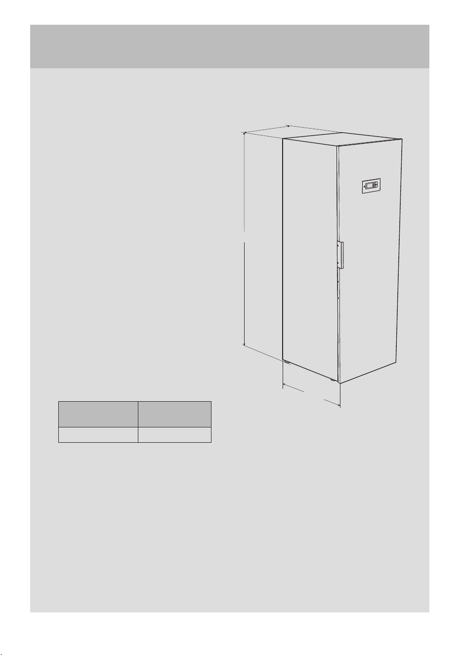
11
A
595
665
PLACEMENT
There must be an earthed socket
within a distance of 2 m from the lower
part of the drying cabinet. The drying
cabinet has a 2 m long earthed lead
with a plug connected at the bottom.
The power socket should be located
such that there is no need for an
extension cable.
It must be possible to reach the socket
easily after the drying cabinet has
been installed. This must also be
borne in mind if the drying cabinet is
built in.
The fl oor where the cabinet is located
must withstand a weight of around 95
kg.
The fl oor must be level with a max
drop of 2.5 cm under the cabinet.
The drying cabinet is intended only for
installation indoors with a temperature
above 15°C.
The drying cabinet must not be placed
in an environment in which high-
pressure water is used for cleaning.
Cabinet
designation
A mm
DC7784 1840
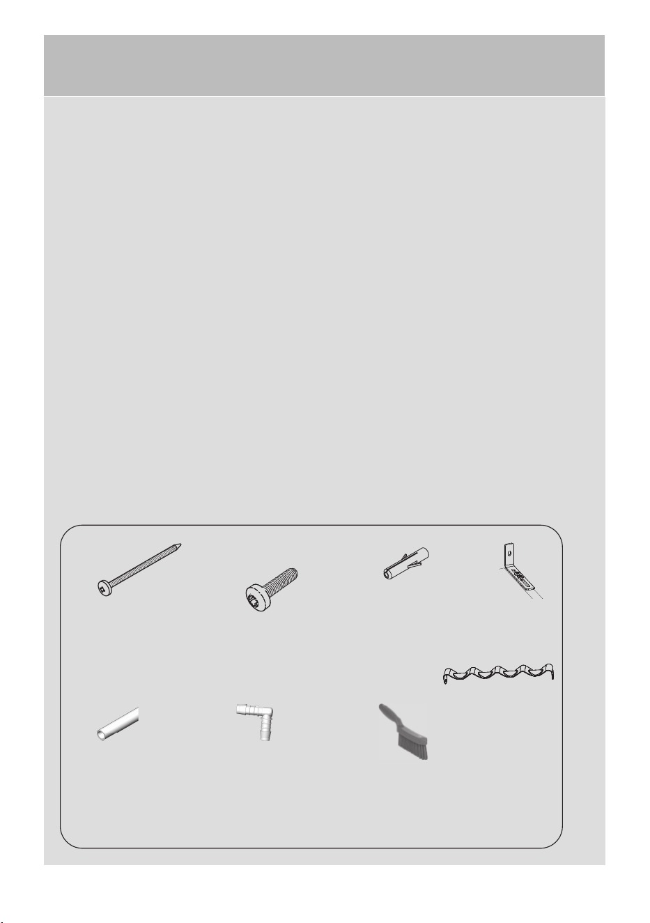
12
2x Screw TRX 5x45
fzk for wall mounting
4x Screw MRT 5x20
for the fi xing bracket
2x Plastic
plug
2x Bracket
for wall
attachment
1.5 m Plastic
hose 10 x 13
1x Nipple for
water hose
Hand brush for
fi lter
2x Clothes
hanger rack
____________________________________
Check to make sure that the product has
not been damaged in transit. Any damage
incurred in transit must be reported to the
dealer within 7 days.
____________________________________
____________________________________
After unpacking, check that the product is
intact. Damage, defects and any missing
parts must be reported to the dealer.
____________________________________
_________________________________
Check that all transport securing devices
have been removed before connecting
the drying cabinet.
_________________________________
_________________________________
Packaging materials such as plastic and
Styrofoam must be kept out of the reach
of children.
________________________________
Complete delivery must include:
Cabinet with pre-installed dehumidifi er
Assembly kit
User Manual
ASSEMBLY KIT
UNPACKING
13
4
3
2
1
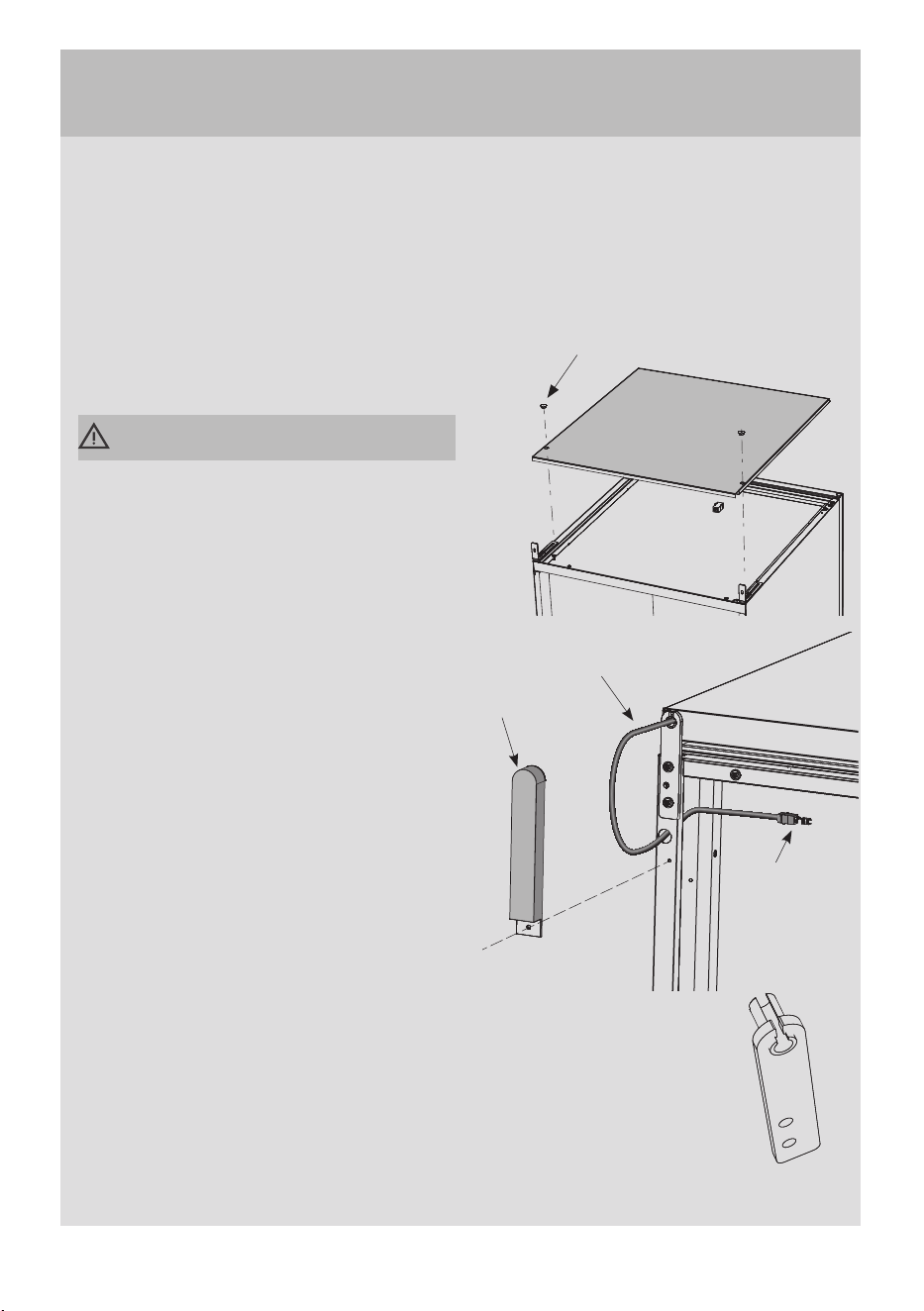
REHANGING OF DOOR
1 Detach the two screws holding the outer roof.
The screws are located beneath the blind
plugs (1). as illustrated, and remove the roof.
2 Remove the protective cover (2) on the upper
hinge and separate the door cable (3) from
the connector (4). Thread the cable through
the hole in the chassis and stretch out the
cable.
3 Remove the upper hinge and release the
cable from the hinge. The hinge has a slot
through which the cable can be threaded.
See illustration.
Release the door from the hinge and togeth-
er with the control cable lay it aside.
4 Fit the new replacement hinge, which is
included in the rehanging kit, on the opposite
side. Use the same screws as previously.
The pictures below illustrate rehanging from right-hung door to left-hung.
Rehanging kit
For rehanging, a rehanging kit must be ordered from the supplier of the cabinet. The kit
consists of a new upper hinge, as the left and right hinges are not interchangeable. The kit
also includes a control cable for fi tting in the door with associated hinge bushing.
Lay the cabinet down carefully on
its back.
_______________________________
NB
Before placing the cabinet on its back, take out
and empty the water tank.
______________________________________
Upper hinge with slot
for cable
OUTER
ROOF
14
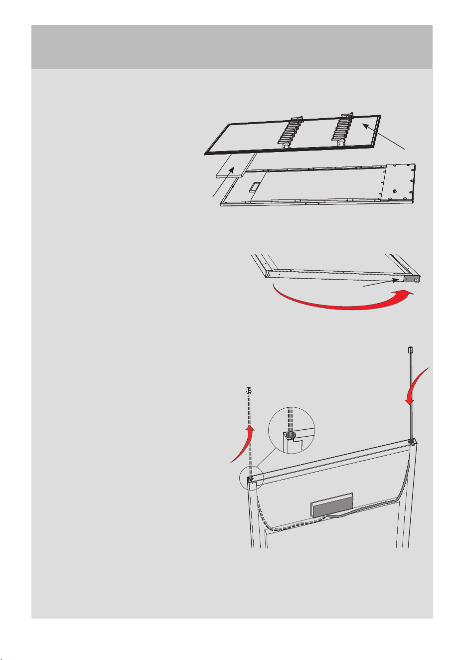
5
6
7
Reconnection in the door
5 Lay the door down with the in-
side facing up on a non-dam-
aging surface.
6 Detach the inner plate (5)
with magnetic strips, glove
hangers and, if applicable,
door hangers. Screws are
beneath the magnetic strips.
Move the insulation into posi-
tion(6).
7 Detach and transfer the reinforce-
ment plate with lower hinge bush-
ing (7) in the door to the opposite
side.
8 Detach existing control cable from
control panel and pull cable out with
hinge bushing (8). Discard the cable
as there is a new complete cable in
the rehanging kit.
Fit the new cable on the opposite side
- press the bushing fi rmly into the hole
and connect the cable to the control
panel socket.
9 Move back the insulation and inner
plate with magnetic strips and, if
applicable, hangers.
Existing control
cable
New control
cable
15
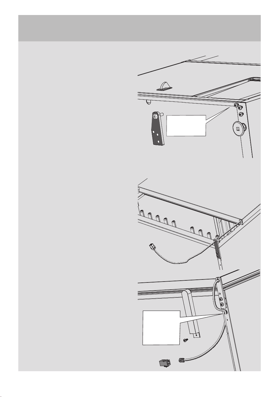
Lay the door in position
10 Before laying the door in position,
remove the lower hinge with pin and
washer and lay it aside. Screw back
the fi xing bolts as they contribute to the
stability of the cabinet.
11 Lay the door in position and introduce
the control cable through the slot in the
new upper hinge, and slide the door
onto the hinge pin.
12 Connect the control cable to the con-
nector in the upper part of the drying
cabinet. The control cable must be
pulled through the hole as illustrated.
13 Refi t the protective cover over the
hinge and the roof of the drying cabinet
removed under point 1.
Lower
hinge
Screw back
the retaining
screws
The cabinet viewed from
below
New upper
hinge
The control
cable must
be pulled
through the
hole.
16
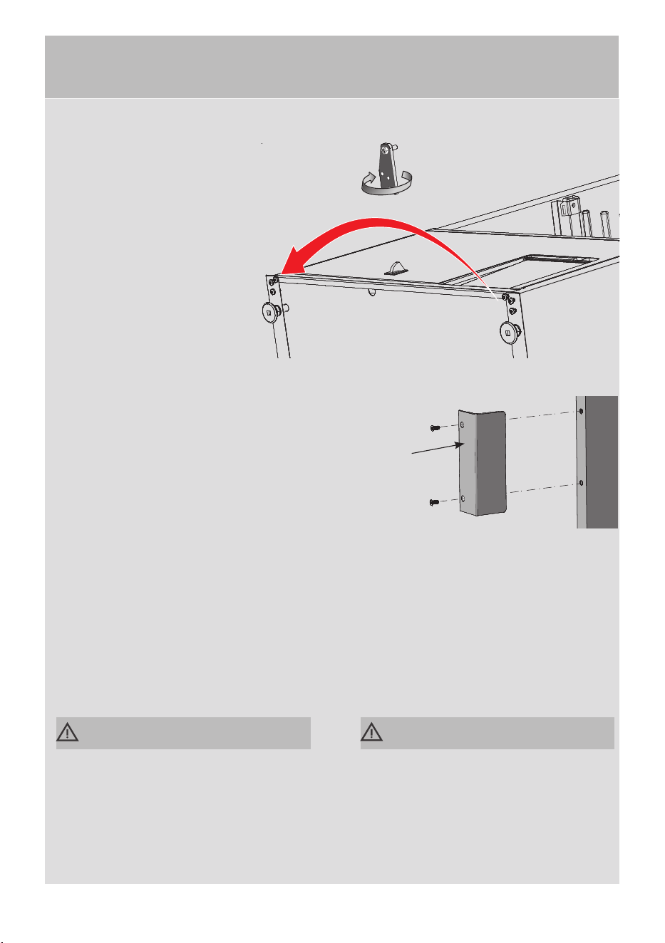
9
14 Transfer the hinge to the
other side. The hinge must
be mirror-inverted and the
hinge pin must be un-
screwed and refi tted on the
other side of the hinge.
Make sure that the hinge
pin is tightened fi rmly.
Transfer the door handle
15 Transfer the handle (9) to the other
side.
Fit the cover plugs for the old holes by
hand. Cover plugs are supplied in the
assembly kit.
Raise the cabinet
16 Raise the cabinet and place it in
position and secure the cabinet to
the wall.
Lower hinge mirror-
inverted
Door handle
_____________________________
NB
Wait at least 1 hour before using the cabinet
again. This is to allow time for the oil in the
compressor to fl ow back. The compressor
may otherwise be damaged.
____________________________________
_____________________________
CAUTION
The drying cabinet must not be used without
being secured to a wall owing to the risk of
tipping over forward.
____________________________________
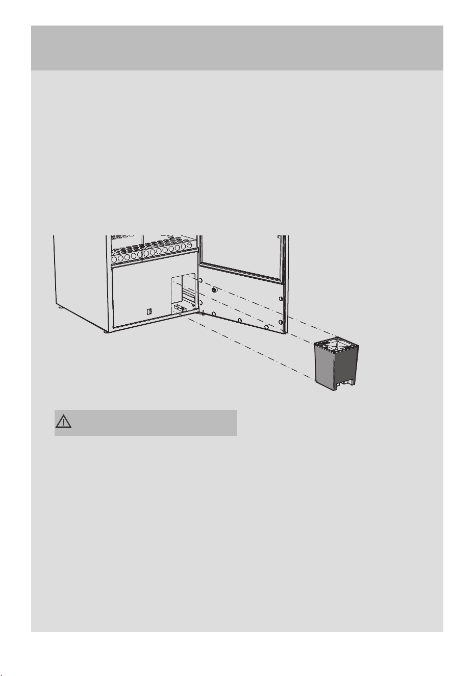
17
CONDENSATION WATER
Condensation water may be removed in two ways, collected in a detachable water tank or
via a hose to the fl oor drain.
DETACHABLE WATER TANK
_____________________________
NB
The water tank is designed to be suffi ciently
large for a complete wash by a comfortable
margin. But make a habit of always emptying
the water tank before each drying operation.
____________________________________
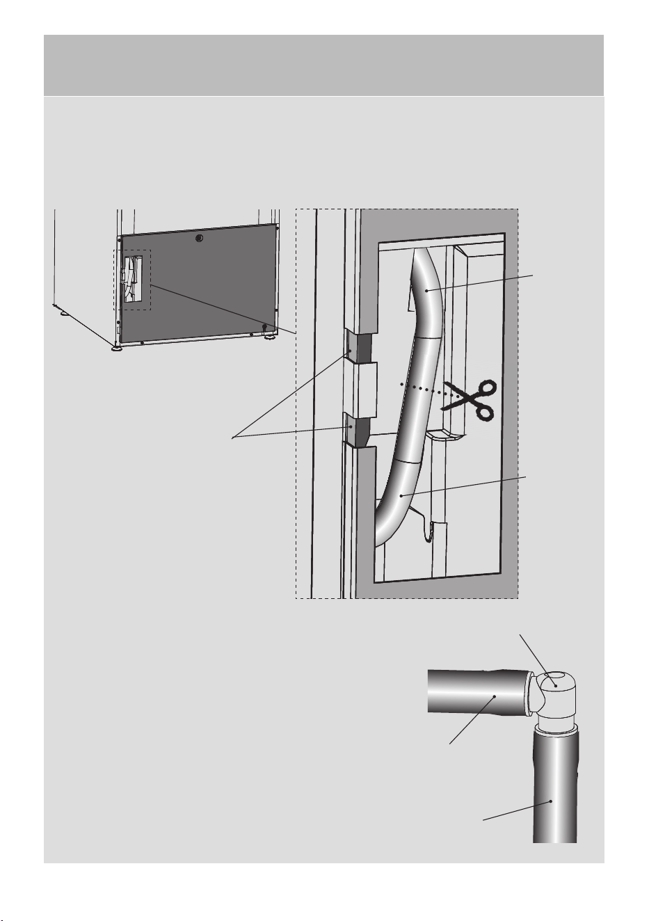
18
1 Carefully pull the upper part of the hose out
around 2 - 3 cm.
2 Trim the hose in the middle of the opening.
3
Install the new drain hose with the nipple
supplied in the assembly kit as illustrated. Push
the hose on without hose clips.
4
Position the drain hose in one of the
recesses in the sheet metal so that there is
no risk of the hose being crushed.
CONNECTION TO FLOOR DRAIN
The drying cabinet is supplied from the factory with a hose to the detachable water tank.
To change to removal of condensation water to the fl oor drain, proceed as follows:
Cabinet viewed from rear
Position the drain
hose in one of the
recesses in the
sheet metal
New hose to
drain
Nipple
Trimmed
hose from
condensation
water pump
Hose to
the de-
tachable
water tank
Hose from
condensa-
tion water
pump
19
5 Route the drain hose to the drain.
6
If the drain is higher than the outlet on the cabinet, make sure that the hose runs to the fl oor in an
arc and forms a trap. There is otherwise a risk of the condensation water fl owing back to the tray
when the pump is not working. This may cause the tray to be fi lled with water and the cabinet to
stop working.
RECONNECTION TO WATER TANK
If you wish to reconnect the condensation water to the water tank, all you need to do is to connect
the two hoses together again with the nipple.
_____________________________
NB
Do not under any circumstances bend the
hose so that water fl ow is prevented.
____________________________________
20
INSTALLATION
POSITIONING/ATTACHMENT
LEVELLING
The drying cabinet must be level on
a fl at surface, resting on all four feet.
Adjust the adjustable feet from the outside.
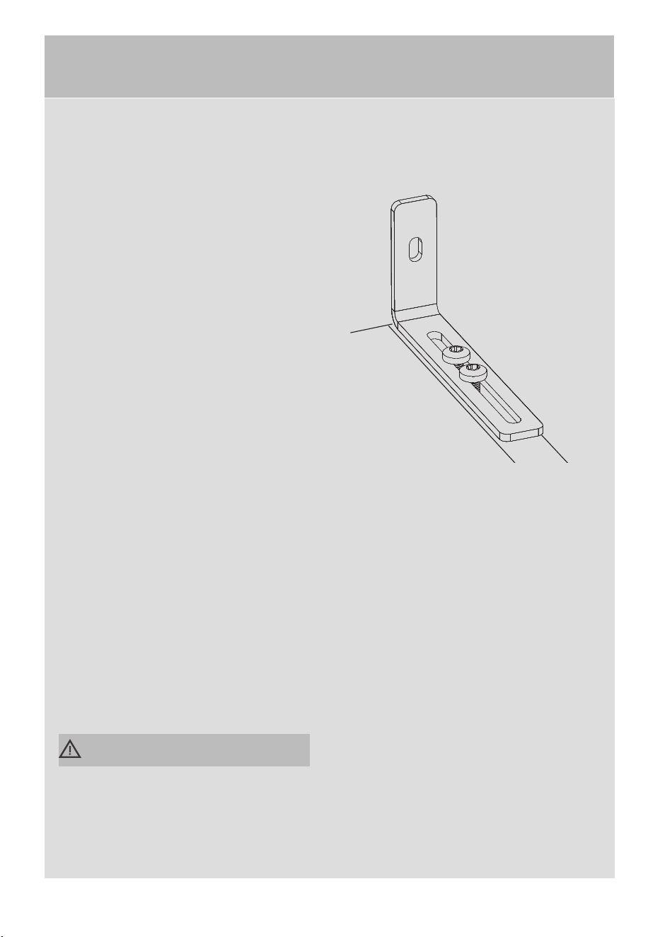
ATTACHMENT TO WALL
The cabinet must be attached to a wall to
prevent tipping over.
The assembly kit includes two angle
brackets that are fi tted on the top of the
drying cabinet, as illustrated. Use the screws
supplied. The brackets have slots for fi tting to
the wall.
Fix the cabinet to the wall. Screws for fi xing,
washers and plastic plugs are supplied in the
assembly kit.
___________________________________
The drying cabinet must not be placed in an
environment in which high-pressure water
is used for cleaning.
¯¯¯¯¯¯¯¯¯¯¯¯¯¯¯¯¯¯¯¯¯¯¯¯¯¯¯¯¯¯¯¯¯¯¯¯¯¯¯¯¯¯¯¯¯¯¯¯¯¯¯¯¯¯¯¯¯¯
___________________________________
The drying cabinet is intended only for
location indoors in a dry place.
¯¯¯¯¯¯¯¯¯¯¯¯¯¯¯¯¯¯¯¯¯¯¯¯¯¯¯¯¯¯¯¯¯¯¯¯¯¯¯¯¯¯¯¯¯¯¯¯¯¯¯¯¯¯¯¯¯¯
_____________________________
CAUTION
The drying cabinet must not be used without
being attached to a wall owing to the risk of
tipping over forward.
____________________________________
Fixing bracket
Top of drying
cabinet
21
ELECTRICAL CONNECTION
The drying cabinet must be connected to a
230 V single-phase 50 Hz and protectively
earthed wall socket.
The drying cabinet is supplied ready for
connection with a cable and an earthed plug.
____________________________________
The drying cabinet should be connected to
an earthed wall socket using the connecting
cable supplied and must not be permanently
wired.
____________________________________
____________________________________
The socket should be located so that the
plug can be easily pulled out if necessary.
____________________________________
____________________________________
Check that the connection current agrees
with the data on the identifi cation plate and
that the power cord is earthed correctly in
accordance with applicable standard. We
recommend that the power cord be fi tted with
a residual current device (RCD).
____________________________________
____________________________________
The drying cabinet should be connected to a
dedicated circuit.
____________________________________
____________________________________
The manufacturer cannot be held liable if the
electrical connections are not carried out as
prescribed in this manual.
____________________________________
22
START-UP
1 Make sure that the cabinet is fi rmly
attached to the wall. See page 20.
2 Make sure that no packaging
material has been left behind.
3 Use a mild detergent with hot water
and wash the inside and outside of
the drying cabinet. Dry carefully. See
also the ‘Care’ section later in the
manual.
________________________________
Read this User Manual
before using the drying
cabinet for the fi rst time.
¯¯¯¯¯¯¯¯¯¯¯¯¯¯¯¯¯¯¯¯¯¯¯¯¯¯¯¯¯¯¯¯¯¯¯¯¯¯¯¯¯¯¯¯¯¯¯¯¯¯¯¯¯¯
____________________________
CAUTION
Read the safety instructions on page 5
before using the cabinet.
___________________________________

23
OPERATION
There are three sections with hangers in the cabinet. Each section has a number of rails for
hanging items to dry.
Hang the items in the drying cabinet according to how much space they require - not
according to their weight.
Fold up the two bottom hanger sections if long items are to be dried.
Hang gloves, caps, scarves and similar items on the hanger strips on the inside of the door.
Pull the hanger hooks in the upper hanger section forward so that the washing can be hung more
easily. Push them back when not in use.
Do not overload the drying cabinet. If you do, the washing will become creased and dry
unevenly. Instead, leave a space between the items of clothing if possible.
If there is a risk of particular items shedding colour, free space should be left around them.
Do not place shoes or similar items on the shoe rack in such a way that they obstruct air fl ow.
Avoid drying heavy items of clothing together with lighter items as they have very diff erent
drying times.
Do not hang knitted items. These will stretch unnecessarily as they are heavy when wet.
Avoid hanging fabrics that are dripping wet in the drying cabinet as the drying cabinet is not
intended to collect large quantities of water.
This also leads to abnormally long drying times.
24
USER TIPS
Always following the washing instructions on the item of clothing if present.
If a fabric conditioner or anti-static agent is used, follow the manufacturer's instructions for
use of this product.
Remove washing that it is already dry. This will reduce drying time for remaining washing.
_____________________________
CAUTION
Do not dry clothing or similar items that
have been treated with petrol or other highly
volatile and infl ammable substance. This
may lead to the formation of an explosive gas
mixture.
____________________________________
_____________________________
NB
If the sealing strip does not close completely
tightly or if the door has a tendency to open,
this may be due to the cleaning fi lter not
having been installed correctly. Make sure
that the cleaning fi lter and the fi lter holder
are pressed down fully so that no air leakage
occurs.
____________________________________
____________________________
NB
When the cabinet is cold it may happen
that the sealing strip of the door does
not close completely. However, this is
fully compensated when the cabinet is in
operation as the sealing strip expands.
___________________________________

25
DRYING PROGRAMMES
The drying cabinet is equipped with two automatic programmes for the drying process:
NORMAL DRY
EXTRA DRY
The programmes automatically close the drying process when the fabrics are dry.
SELECTION OF DRYING PROGRAMME
NORMA DRY – Used for drying of items of normal thickness.
EXTRA DRY – Used for drying of thicker items, deep drying.
CHILD LOCK
A child lock function can be activated to make sure that the drying process is not stopped or
started by mistake
FUNCTION OF THE CHILD LOCK
Activation buttons must be held down for a least 3 seconds (delay time).
ACTIVATION / DEACTIVATION OF CHILD LOCK
The child lock is activated and deactivated via a setting parameter described on page 28. When
this function is activated, a clock symbol appears on the display.

26
STARTING DRYING PROGRAMME
LAST USED DRYING PROGRAMME
Press the on/off switch to the “ON” position - Indicated by the display lighting up and showing
the last run programme.
If you want this, press START/STOP.
Or select another drying programme by stepping through with the buttons ARROW UP or
ARROW DOWN.
Then start the drying programme with the START/STOP button.
DOOR OPEN
If the door is open when a drying programme is started and the START/STOP button is
activated, the display will show “close door”.
Close the door, and the selected drying programme will start.
IN OPERATION
The animated symbol (bar) on the left side of the display indicates that the drying process is
in progress.
CONDENSATION WATER TANK
If the condensation water tank becomes full, the drying process will be interrupted
immediately and the display will show ”check water tank”. Empty the water tank and re-
start the drying process.
COOLING
During the cool-down period the display shows the text ”cool” and a count-down of the
remaining time (5 minutes).
OPERATION
27
END OF PROGRAMME
When the cool-down period has ended, the drying process is fi nished, and the display shows
the text “end” (fl ashing).
When the START/STOP button is then pressed, the current programme ends and the display
shows the last used programme.
ENDING DRYING PROGRAMME
To interrupt a drying process in progress, press START/STOP.
DOOR OPENED
If the door is opened while the drying process is in progress, the drying process will continue
for another 5 minutes. The display shows “close door” and counts down the 5 minute
programme pause period.
If the door is closed within this 5 minute period, the drying process will continue.
If the door is left open, the drying process will stop after 5 minutes and must be restarted
manually.
If you wish to stop the drying process immediately, without a 5 minute period, press START/
STOP.
_____________________________
NB
In standby mode the display goes off after 10
minutes and lights up when any of the buttons
on the control panel is activated or the door
is opened.
____________________________________
____________________________
NB
Empty the condensation water tank after
each drying process.
___________________________________

28
SETTING OF DRYING PROGRAMME
There are ways of optimising the two automatic programmes of the drying cabinet for best possible
results.
The setting is adjusted on the control panel for the programme concerned.
Adjustments must be made if it is found that the
Washing does not dry suffi ciently.
Washing is over-dried – Long drying time.
INTRODUCTION
The drying cabinet's two automatic programmes stop automatically when the laundry is dry.
To
decide when the washing is dry, a measured value is compared against a factory-set parameter.
Parameter P 2072 for NORMAL DRY drying programme and
Parameter P 2071 for EXTRA DRY drying programme.
It is primarily these two parameters that are adjusted to optimise the drying process.
The NORMAL DRY programme is controlled by a moisture sensor.
EXTRA DRY programme is controlled by a moisture sensor and a time factor.
If it is found that the washing does not dry suffi ciently in the:
NORMAL DRY
drying programme, the parameter value for P 2072 is reduced.
EXTRA DRY drying programme, the parameter value for P 2071 is increased.
If it is found that the washing is over-dried, long drying time in the:
NORMAL DRY
drying programme, the parameter value for P 2072 is increased.
EXTRA DRY drying programme, the parameter value for P 2071 is reduced.
Drying processes must always be optimised in small steps; start by adjusting the parameter
concerned 1-2 units up or down, then check the result after the next drying process and make a
further adjustment if necessary.
29
+
p105
OFF ON
+
Setting to optimise the drying cabinet's automatic programme is done using the buttons on the
control panel when the drying cabinet is in programming mode.
RETURN TO OPERATING MODE
To return to operating mode, press DOWN ARROW and then OK.
PROCEDURE
1 Step through to the relevant parameter by pressing the UP ARROW or DOWN ARROW key
repeatedly. If you go too far, simply continue stepping through until the display shows the
correct parameter.
2 When the display shows the correct parameter, for example “P 2072”, press OK to confi rm
parameter selection. The row now fl ashes with the set value of the parameter.
3 Increase or reduce the parameter value using the UP ARROW or DOWN ARROW key.
4 To save the set value, press OK.
PROGRAMMING MODE
Make sure that the main ON/OFF switch on the drying cabinet is turned off . The display is
unlit.
Hold down the UP ARROW and DOWN ARROW buttons simultaneously and
press the ON/OFF switch. The display lights up and shows the fi rst setting parameter
according to the list below.
30
+
OFF
+
Parameter Name
Factory
pre-set
Min
value
Max
value
Designates
P105
Language 1 0 7 1=Swedish
Setting see page 10
P115
Child lock
On/Off
0 0 1 0 = Child lock OFF
1 = Child lock ON
P2071
Extra dry 30 0 60 Control EXTRA DRY drying
programme
P2072
Normal dry 27 20 70 Control NORMAL DRY drying
programme
P2073
Max
operating
time
240 (min) 60 360 Control max permitted operating
time
PARAMETER LIST
SETTING OF DRYING PROGRAMME
RESTORING TO FACTORY SETTING
1 Make sure that the main ON/OFF switch on the drying cabinet is turned off . The display is
unlit.
2 Hold down the UP ARROW and DOWN ARROW buttons simultaneously and press the
ON/OFF switch.
Last run programme is
shown
3 Hold down the UP ARROW and DOWN ARROW keys simultaneously and press OK.
The factory settings are saved and the display shows the last run programme.
31
CARE
CLEANING
____________________________
NB
A replacement lead may be in
stalled only by
the manufacturer, the
manufacturer’s service agent or other
qualifi ed electrician.
___________________________________
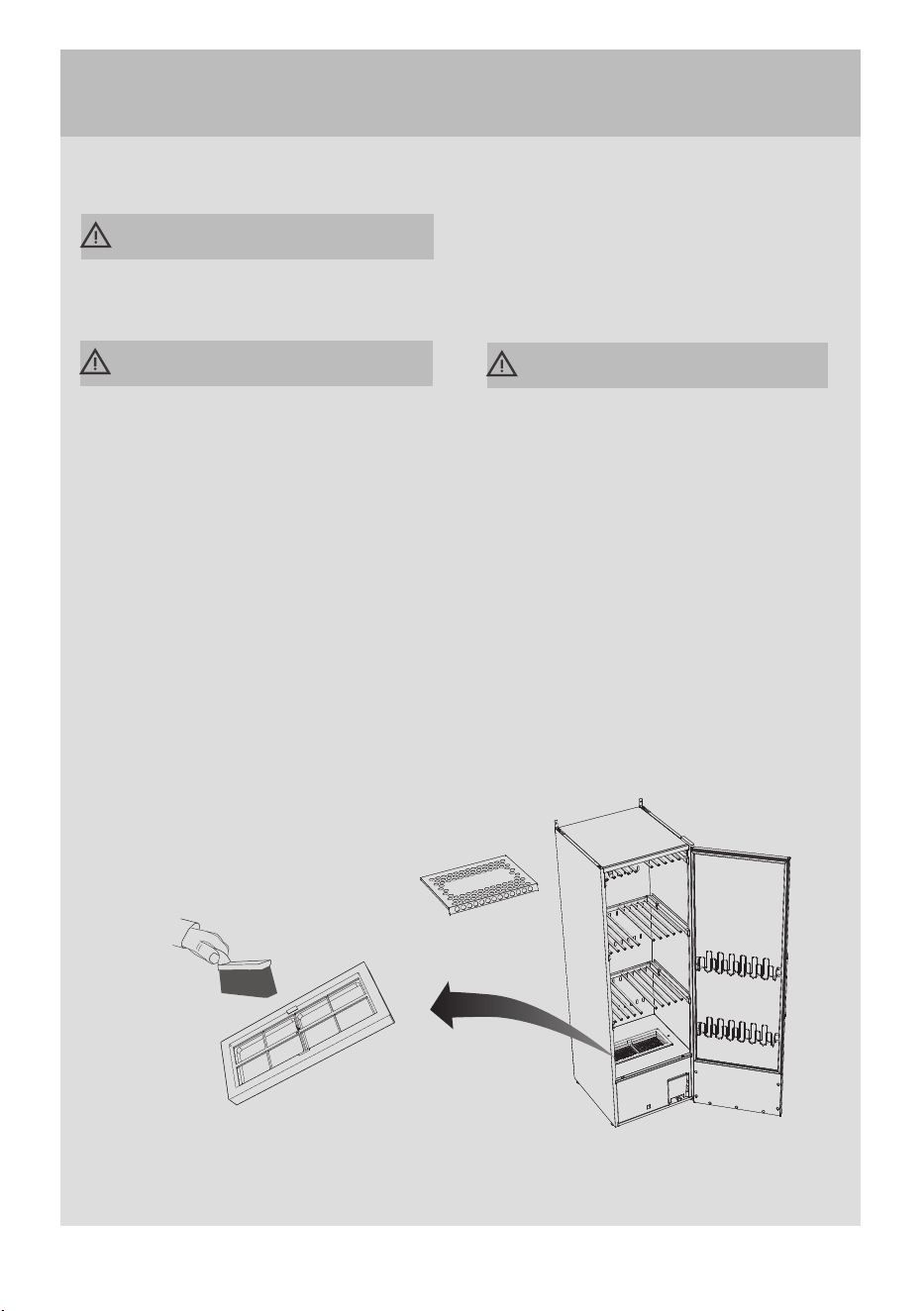
Clean the walls of the cabinet with a mild
soap solution on a damp cloth.
Before each drying process the shoe rack
must be removed and the cleaning fi lter,
located below the rack, must be cleaned.
See illustration.
Brush the cleaning fi lter clean with the brush
supplied.
_____________________________
NB
Do not use high-pressure cleaning.
____________________________________
REPLACEMENT PART
If the mains lead for any reason is damaged,
it must be replaced. A genuine spare part
can be obtained from the dealer who
supplied the cabinet.
_____________________________
NB
Cleaning and maintenance must not be
performed by children without supervision.
____________________________________
Shoe rack
Cleaning fi lter
32
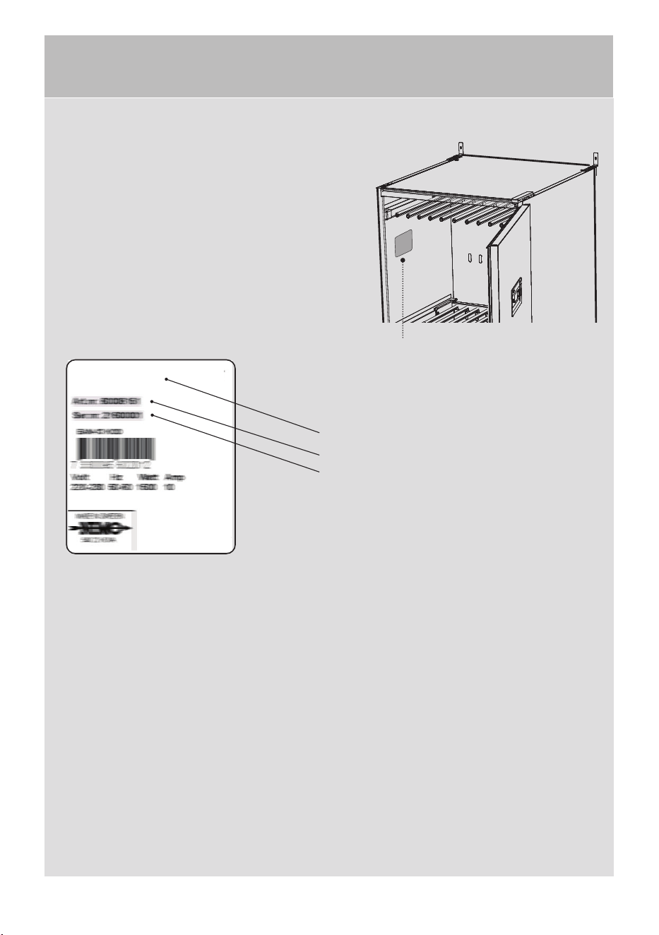
ASKO DC7784HP
Name of the drying cabinet
Article number
Serial number (12 digits)
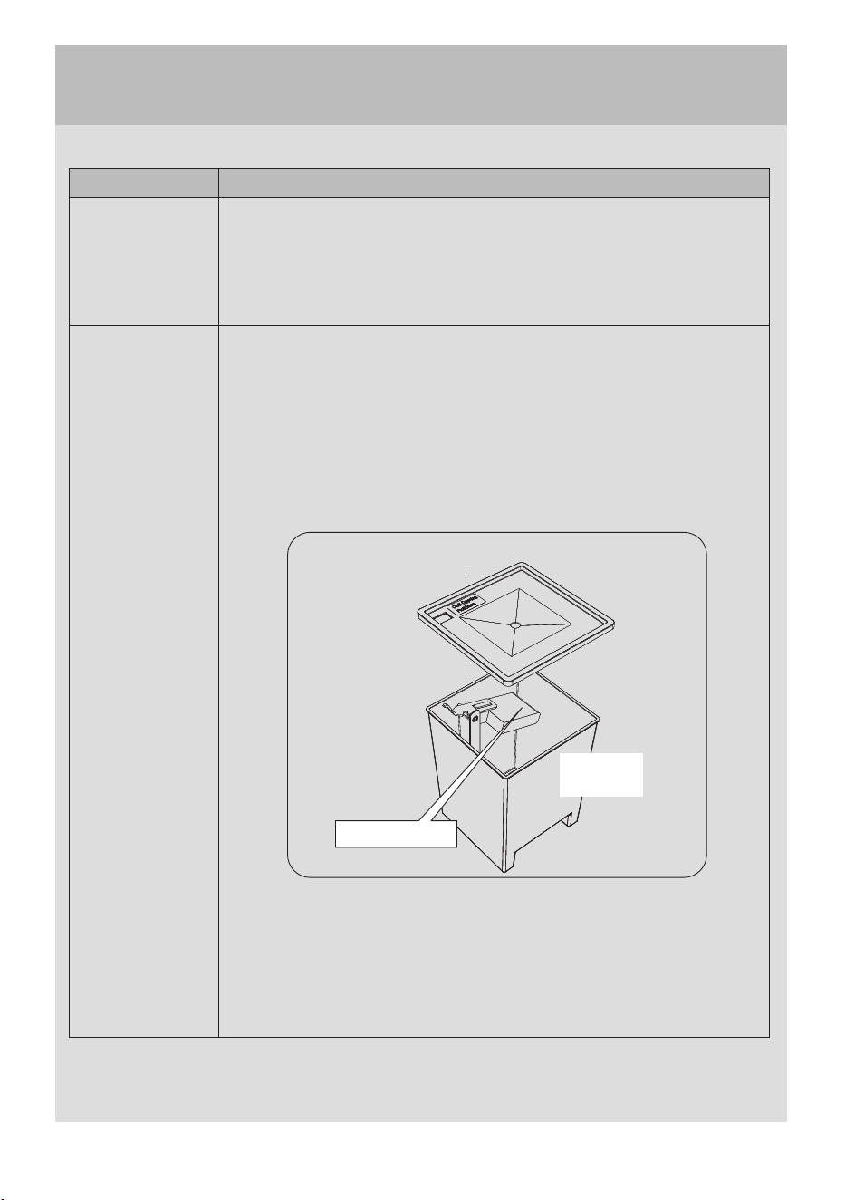
SERVICE
Before contacting Service, you should
fi nd out the name, article number and
serial number of the drying cabinet.
This information can be found on
the drying cabinet located inside the
cabinet.
Identifi cation plate (inside)
The illustration shows the
identifi cation plate for the
DC7784HP drying cabinet
33
Questions Action
The drying
cabinet is not
working.
1. Check that the mains lead is connected to a power socket.
2. Check that no fuse has tripped.
3. Have you pressed the start button?
4. Is the door closed?
5. Is the water tank in place and emptied?
The display
shows Check
water tank
1. Empty the water tank
2. Check that the lid is fi tted so that the fl oat arm protrudes out of the
opening in the lid and that the arm runs freely.
3. Check that the water tank is turned so that the fl oat arm is inside the
tray.
4. If none of the above work, the defective pump safety switch may have
been activated. Contact Service.
TROUBLESHOOTING
This side
forwards
Float in water tank
Water tank with lid removed
34
Questions Action
The display
shows CLOSE DOOR
1. Check that the door closes tightly so that the door switch is activated.
(Located at the bottom of the cabinet on the cover plate in front of the
heat pump unit).
2. If necessary, try to tape the switch in position and check whether the
warning on the display disappears.
3. If none of the above work contact Service.
The display
shows an
alarm/error
code
This should normally not happen, but if an alarm or error code appears,
fi rst try to reset the alarm by holding the START/STOP button down for
5 sec.
If the problem persists, consult the error code list on page 33 to try to
locate the fault. Try to rectify the indicated fault, but if the fault persists
the unit (the heat pump box) must be replaced. Contact Service.
Drying takes a
long time.
1. Clean the fi lter (this should preferably be done after each drying
operation).
2. Check that the water tank is empty.
3. Make sure that the correct programme has been selected for the
type of washing.
4. Make sure that the washing is not soaking wet (poorly spun).
5. Make sure that too much washing has not been hung up.
6. Adjust parameters P2072 and P2071 as described in the chapter on
SETTING DRYING PROGRAMME.
The washing
does not become
dry.
1. Make sure that the correct programme has been selected for the type
of washing.
2. Make sure that too much washing has not been hung up.
3. Adjust parameters 2072 and 2071 as described in the chapter
SETTING DRYING PROGRAMME.
The sealing strip
does not seal
tightly, the door
is ajar.
1. Check that the cabinet is level. Check with a spirit level, adjust if
necessary with the adjusting feet.
2. Check that the cleaning fi lter and its holder are correctly fi tted. The
holder must be pressed down against the underlying heat pump unit
and locked with the revolving mounting brackets to seal properly.
3. Check that no litter, gravel or similar has ended up beneath the holder
of the cleaning fi lter, as the fi lter will not seal satisfactorily if this is the
case.
35
LIST OF ERROR CODES
No. Name Description
ERROR 03 Fault on moisture sensor Sensor is outside its measurement
range
Contact Service.
ERROR 04 Max time process Max time for drying process exceeded
(pre-set value 240 min can be changed
with parameter P 2073).
ERROR 06 Check water pump Water level in tray too high, has
activated switch at fl oat.
Contact Service.
ERROR 12 Timeout communication The communication between user
interface and electronics has been
temporarily interrupted.
Contact Service.
To reset the alarm, hold down the START/STOP button
for 5 sec.
Describes relevant error codes for this product.
36
TECHNICAL DATA
Capacity:
5.0 kg laundry (cotton)
Dewatering capacity:
22 g/min
Electrical supply:
Single-phase 220 - 240 V, 50 Hz, 10 A
Power:
900 W
Capacity of main fan:
945 m³/h (free blow)
Capacity of sub-fan:
160 m³/h (free blow)
Hanging length:
16 metres
Dimensions: DC7784HP:
Height 1840 mm
1855 mm incl. hinge
Width 595 mm
Depth 665 mm
691 mm, incl. door handle
Weight of DC7784HP:
93 kg
Sound level:
A-weighted emission sound pressure level
is less than 70 dB(A)
Leaktightness test:
28 bar
This product contains fl uorinated greenhouse gases.
Type of refrigerant:
R407C
Quantity of refrigerant:
0.30 kg
Total global warming poten-
tial factor:
1774
CO2 equivalents: 0.532 t
Hermetically sealed.
37
MANUFACTURING STANDARDS
See cabinet identifi cation plate.
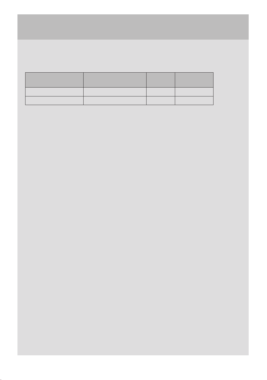
ENERGY CONSUMPTION AND DRYING TIMES IN DRYING OF SPUN LAUNDRY *)
Programme Energy consumption
kWh/kg laundry
Drying
time
Temp. max
NORMAL DRY 0.3 90 min 55
°C
EXTRA DRY 0.4 120 min 55 °C
_______________________________
*) Values may vary depending on:
- spin speed
- temperature, air humidity in the room
- air circulation in the room (supply air, exhaust air)
¯¯¯¯¯¯¯¯¯¯¯¯¯¯¯¯¯¯¯¯¯¯¯¯¯¯¯¯¯¯¯¯¯¯¯¯¯¯¯¯¯¯¯¯¯¯¯¯¯¯¯¯


Gematech Innovation
427001114 / 03
ASKO DC7784HP UK
www.asko.com
en (02-19)
Right to make changes reserved.