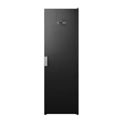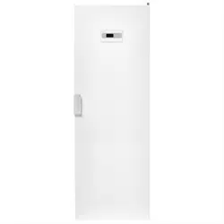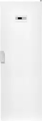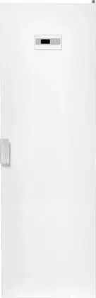
USER MANUAL Drying cabinet DC7774V
DC7784V
Read the user manual before using the machine

Dear ASKO customer,
Congratulations on the choice you have made, and welcome
to the ASKO family, a global family with its roots in Sweden.
We at ASKO thank you for your trust and hope that you will
enjoy using your new drying cabinet.
A good drying cabinet should be well designed, dry clothes
well, have a low
environmental impact, be user-friendly, save time and
energy, have a long service life and be reliable. ASKO meets
all these requirements.
When you buy an ASKO product you can be sure that the
inside is just as
good as the outside and that the ethics and morality that
go into manufacturing this product are just as high as the
quality and function you are getting. That's what Swedish
quality is all about.
Before using the product for the fi rst time, please read the user
instructions and the advice on caring for the product. This
will help you get the best possible results from your product
and all its functions.
If you have any questions, do not hesitate to call us or to
contact us through our website.
Best wishes from Sweden and the ASKO team.

3
CONTENTS
The contents of this user manual describe the function and operation of the drying cabinet,
as well as instructions for installation and maintenance.
THIS USER MANUAL
IMPORTANT SAFETY INFORMATION 4
FOR A GOOD ENVIRONMENT 5
Packaging materials 5
Management of end-of-life
drying cabinet 5
COMPONENTS 6
Control panel 7
Language 8
PLACEMENT 9
INSTALLATION 10
Unpacking 10
Rehanging of door 11
Placement 16
Evacuation / air supply 17
Connection to evacuation 17
Electrical connection 19
BEFORE USING THE
DRYING CABINET 20
OPERATION 21
Arranging laundry for drying 21
User tips 21
Air flow 21
Drying programmes 22
Child lock 23
Start automatic programme 24
Starting a manual programme 24
Tips 25
SETTING DRYING PROGRAMMES 26
Programming mode 26
Parameter list 27
Adjustment 28
Procedure 29
Restoring to factory setting 29
CARE 30
Cleaning 30
Service 30
OVERHEAT CUT-OUT 31
TROUBLESHOOTING 32
TECHNICAL DATA 33

4
IMPORTANT SAFETY INFORMATION
Applicable to installation in the EU
The drying cabinet can be used by children over the age of
8 and persons (including children) with various disabilities or
inadequate experience and knowledge, provided they are kept
under supervision or are given instructions on how to use the
appliance in a safe way and understand the risks that use entails.
Children must not play with the appliance.
Applicable to installation in countries outside the EU
The appliance is not intended for use by persons (including children)
with various disabilities or inadequate experience and knowledge.
They may use the appliance only under supervision or if they have
received instructions on how to use the appliance form a person
who is responsible for their safety.
Children must be supervised to ensure that they do not play with
the appliance.
Applicable to all installation
The drying cabinet must be installed and kept indoors.
If the power cord is damaged, it must be immediately re-
placed, and this must be done only by the manufacturer, the
manufacturer's service agent or similarly qualifi ed persons in order
to prevent danger.
Follow ASKO instructions in repair and replacement of parts
This drying cabinet meets applicable safety requirements. Incorrect
use may, however, lead to injuries and damage to objects.
The advice and caution notices in this manual have been written to
enable you to avoid incorrect use and unnecessary risks of accidents,
and should be read before installing and using the drying cabinet.
CAUTION: This equipment is intended only to be used to dry fabrics
washed in water.
5
FOR A GOOD ENVIRONMENT
PACKAGING MATERIALS
The packaging that protects the drying cabinet
against damage in transit has been chosen
with concern for the environment in mind and
is therefore recyclable.
Packaging that is returned to the material
cycle means reduced consumption of raw
materials and a smaller volume of waste.
MANAGEMENT OF END-OF-LIFE
DRYING CABINET
When the drying cabinet has reached the
end of its useful life, it must be taken to a
recycling centre for disposal. Many parts of
the drying cabinet can be re-used, but it also
contains other material that must be handled
correctly. You should therefore never leave
the drying cabinet or parts of the cabinet for
collection with household waste, as this may
lead to risks to health and cause damage to
the environment.
The end-of-life drying cabinet should instead
be taken to a recycling centre. Check with
your dealer if necessary.
All the plastic parts of the drying cabinet are
marked with internationally standardised
symbols. The parts of the drying cabinet can
therefore be recycled in an environmentally
sound manner by waste separation.
6
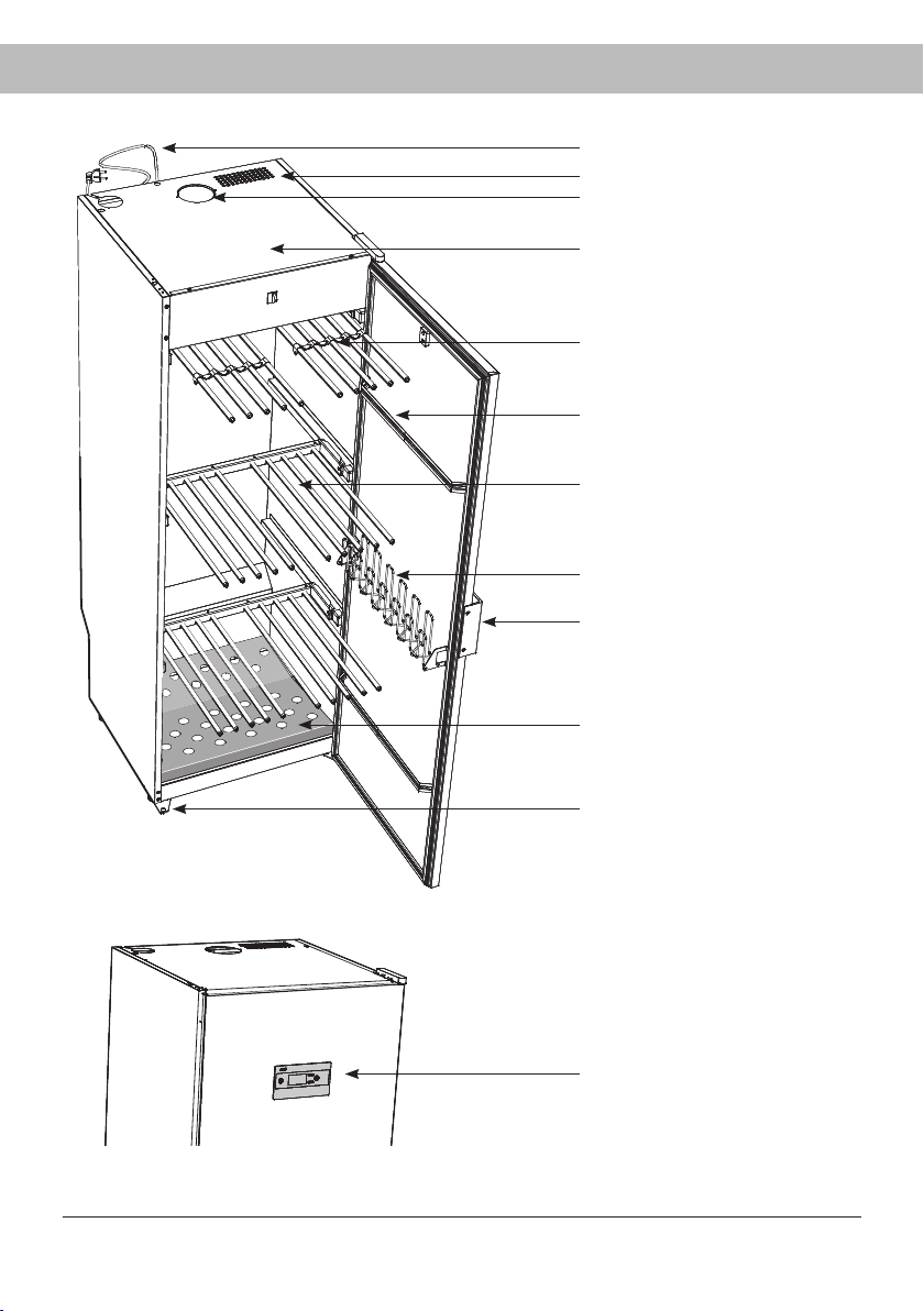
COMPONENTS
Connecting lead
Air inlet
Moist air outlet
Heating and fan components are
combined in the top of the cabinet
in a Fan Unit.
Clothes hanger rack
(accessory - included in certain
models)
Door hangers
Three extendible hanging sections
(The illustration shows extended
sections)
Glove hangers
Door, right or left-hand version
Shoe rack
(accessory - included in certain
models)
Adjustable feet (x4)
Control panel
7
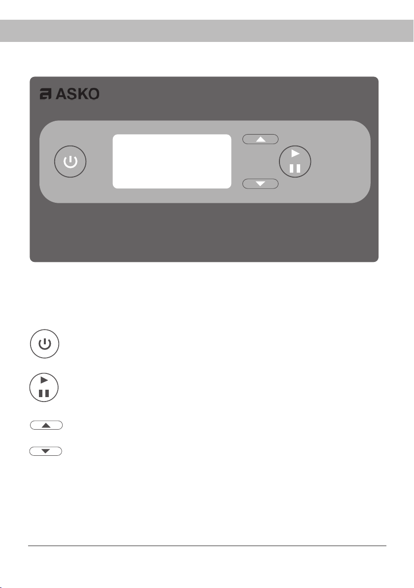
CONTROL PANEL
The drying cabinet is equipped with four automatic and four manual drying programmes
suited to different types of clothing. The programmes are set using the buttons on the menu
panel. Four languages can be handled.
BUTTONS
ON / OFF
START Starts and
STOP stops the drying programme
OK Confi rms the selection of programmes, functions and settings
UP ARROW, increase values or browse between programmes.
DOWN ARROW, reduce values or browse between programmes.
DISPLAY
The display has two rows with 6 characters on each row. During the drying process the se-
lected drying programme and a rolling bar indicating that the process is in progress are shown.
8
SETTING
1 Make sure that the ON/OFF switch on the
drying cabinet is off. The display is unlit.
2 Hold down the UP ARROW and DOWN
ARROW buttons and press the ON/OFF
switch to the “ON” position. The display
lights up and on the top row shows
“P105” fl ashing, which is the parameter
for language setting. If a different value is
shown, use the UP ARROW or DOWN
ARROW buttons to browse to the correct
parameter.
3 Press START/STOP to confi rm.
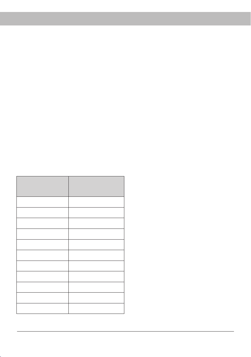
Language sym-
bol
Display language
0 English
1 Swedish
2 Norwegian
3 Danish
4 Finnish
5 Italian
6 French
7 German
8 Spanish
9 Portuguese
10 Dutch
The row for current language now fl ashes.
The languages have a numerical symbol
as shown in the list below.
4 Browse to the desired language with the
UP ARROW or DOWN ARROW buttons.
5 To save the set value, press START/
STOP.
6 To return to operating mode, press DOWN
ARROW and START/STOP.
LANGUAGE
The following languages can be handled: English, Swedish, Norwegian, Danish, Finnish,
Italian, French, German, Portuguese and Dutch.
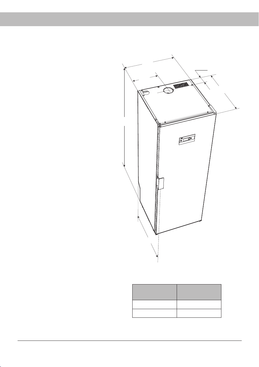
A
595
298
100
608
635
9
PLACEMENT
If the drying cabinet is to be installed
connected to air exhaust ventilation,
this must be available in the room.
There must be an earthed socket
within a distance of 2 m from the
upper part of the drying cabinet.
The drying cabinet has a 2 m long
earthed lead with a plug connected.
The power socket should be located
such that there is no need for an
extension cable.
It must be possible to reach the
socket easily after the drying cabinet
has been installed.
This must also be borne in mind if
the drying cabinet is built into wood-
work or similar. See also the section
on ‘Electrical connection’.
The fl oor where the cabinet is lo-
cated must withstand a weight of
around 60 kg.
The fl oor must be level with a max
drop of 2.5 cm under the cabinet.
The drying cabinet is intended only
for installation indoors with a tem-
perature above 0°C.
The drying cabinet must not be
placed in an environment in which
high-pressure water is used for
cleaning.
Cabinet desig-
nation
A mm
DC7774V 1700
DC7784V 1840
Dimensions in mm
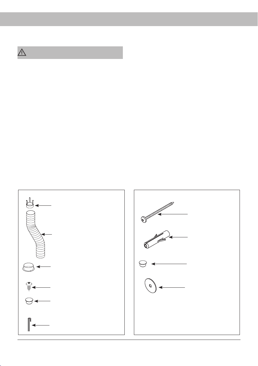
10
Draft stabilizer (1)
Hose (1)
Spigot (1)
Fixing screw for spigot (2)
Cover plug, white (4) for
adjustable feet
Allen key (1)
Screw TRX 5x70
zinc-plated (2)
Wall plug (2)
Cover plug, white (2)
Washer NB (2)
INSTALLATION
______________________________________
Make sure that the product has not been
damaged in transit Any damage incurred
in transit must be reported to the dealer
within 7 days.
______________________________________
Complete delivery must include:
Cabinet with installed fan unit
Assembly kit
User Manual
______________________________________
After unpacking, check that the product is in-
tact. Damage, defects and any missing parts
must be reported to the dealer immediately.
______________________________________
______________________________________
Check that all transport securing devices
have been removed before connecting the
drying cabinet.
______________________________________
______________________________________
Packaging materials such as plastic and
Styrofoam should be kept out of the
reach of children.
______________________________________
ASSEMBLY KIT
- for cabinet
- for attachment to wall
_______________________________
CAUTION
The drying cabinet must be handled carefully
if it is standing unsupported on its pallet.
RISK OF TIPPING OVER
_______________________________________
UNPACKING
2
1
3
4
D
D
D
D
D
11
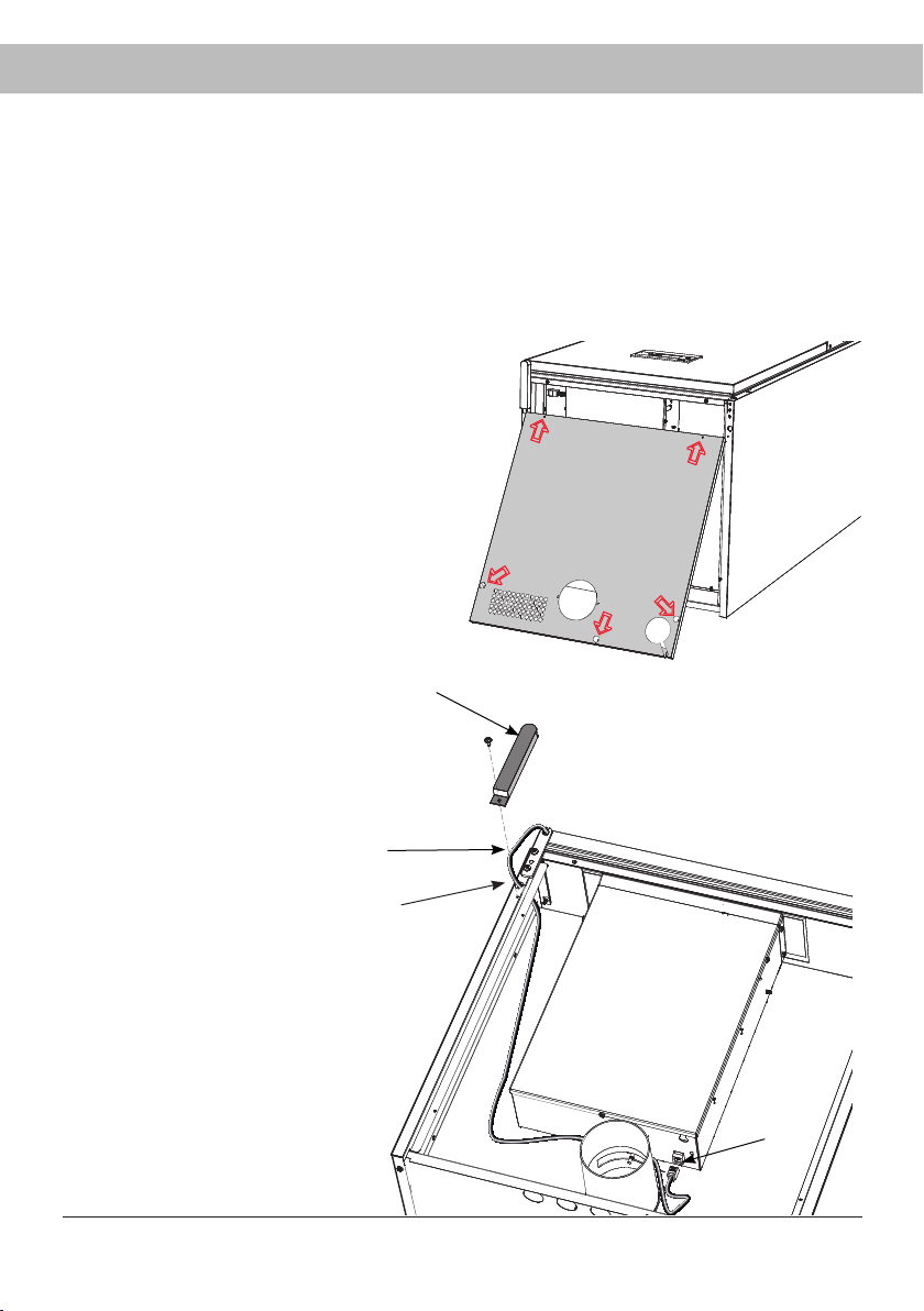
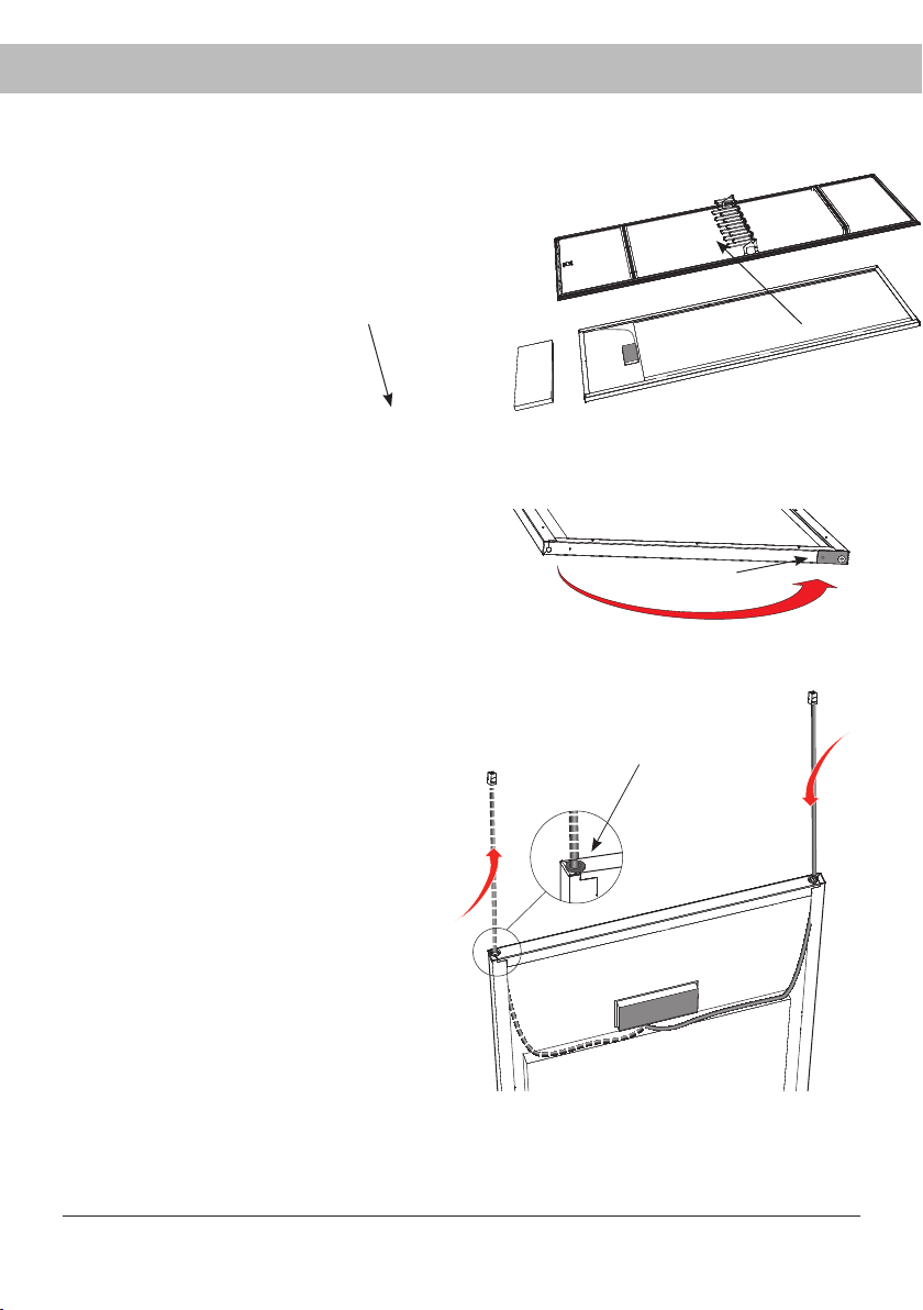
REHANGING OF DOOR
The pictures below illustrate rehanging from right-hung door to left-hung.
Rehanging kit
For rehanging, a rehanging kit must be ordered from the supplier of the cabinet. The kit
consists of a new upper hinge, as the left and right hinges are not interchangeable. The kit
also includes a control cable for fitting in the door with associated hinge bushing.
1 Remove the cover in the top of the
drying cabinet. This is attached with
fi ve screws at the marking arrows.
2 Remove the protective
cover (1) of the upper hinge
and release the control
cable (2).
3 Separate the control cable
from the fan unit with the
quick connector (3) and
pull the cable through the
hole (4).
Lay the cabinet down carefully on its back.
Fan unit
6
5
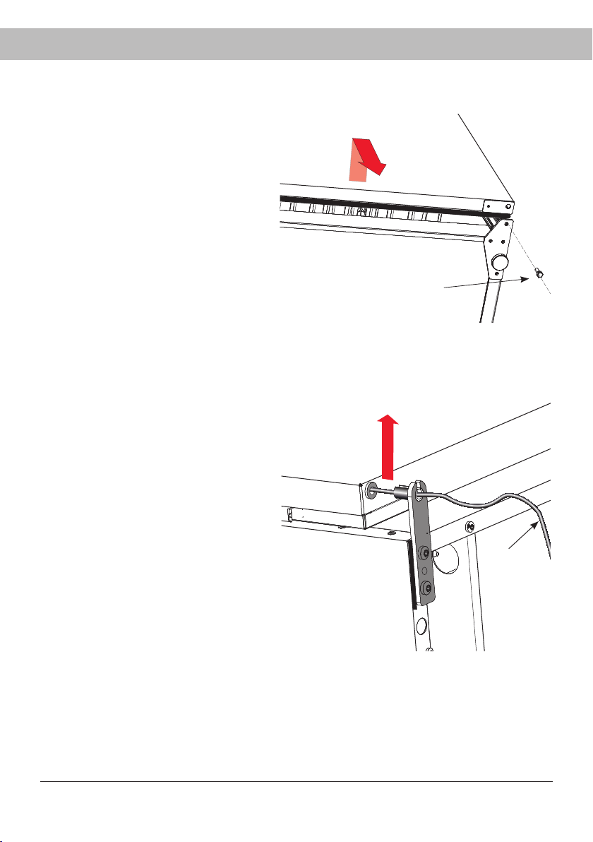
12
Upper hinge joint with the door pulled down
so that the hinge pin is freed
4 Unscrew the lower hinge pin (5).
Raise the door slightly from the
bottom edge and detach it from
the upper hinge, to the extent that
the hinge pin is visible. The pin has
a recess for the control cable.
5 Carefully pull the control cable (6)
out of the recess in the hinge pin.
6 The door, together with the control
cable, is now free and can be set
aside.
7
8
13
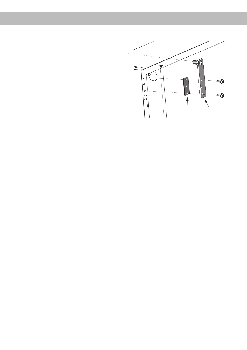
7 Detach the upper hinge (7) with hinge
washer (8). Discard the hinge.
8 Install the new replacement hinge on the
opposite side and move the hinge washer
across.
The hinge forms part of the rehanging
kit, which can be ordered from the sup-
plier of the drying cabinet.
12
9
10
11
14
9 Lay the door down
with the inside facing
up on a non-damag-
ing surface.
10 Detach the inner plate
(9) with magnetic
strip, door hangers
and glove hangers.
Screws are beneath
the magnetic strips.
Remove the insula-
tion (10).
11 Detach and transfer the reinforce-
ment panel and lower hinge
bushing (11) in the door to the
opposite side.
12 Detach existing control cable from
control panel and pull cable out
with hinge bushing (12). Discard
the cable as there is a new com-
plete cable in the rehanging kit.
Fit the new cable on the opposite
side - press the bushing fi rmly into
the hole and connect the cable to
the control panel outlet.
13 Move back the insulation and
inner plate with magnetic strips
and, if applicable, hangers.
Re-attachment in the door
14
13
15
New hinge
Raise the cabinet
19 Raise the cabinet and place it in
position and secure the cabinet
to the wall.
Transfer the door handle
18
Transfer the handle (14) to the other side.
Fit the cover plugs for the old holes by hand.
Cover plugs are supplied in the assembly kit.
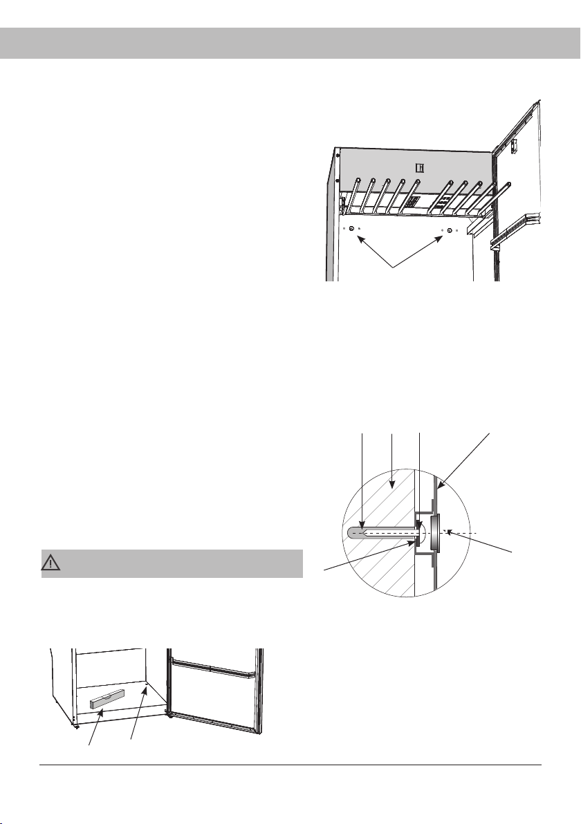
14 Introduce the operating ca-
ble through the recess in the
new upper hinge and slide
the door up on the hinge pin.
15 Install the lower hinge pin.
Make sure that the hinge
pin is tightened fi rmly.
16 Connect the control panel
(13) to the connector in
the upper part of the drying
cabinet.
17 Refi t the drying cabinet cover
which was removed under 1.
Fan unit
The control cable
must be pulled
through the hole.
Lay the door in position
_____________________________
CAUTION
The drying cabinet must not be used
without being attached to a wall owing to
the risk of tipping over forward.
____________________________________
3
2
6
4
7
1
89
5
16
1. Pre-drilled holes
2. Wall plug
3. Wall behind drying cabinet
4. Fixing screws
5. Washer
6. Rear wall of drying cabinet
7. Cover plug
8. Spirit level
9. Cover plug
PLACEMENT
_______________________________________
The drying cabinet is intended only for use in-
doors in a dry place.
___________________________________________
___________________________________________
Do not place the drying cabinet in an area where
high-pressure washing is used for cleaning.
___________________________________________
The drying cabinet must be level on a fl at
surface, resting on all four feet.
Use the Allen key supplied and adjust the feet
through the holes in the baseplate of the drying
cabinet.
Press the four covering plugs fi rmly into the
holes after adjustment.
The cabinet must be attached to a wall to
prevent tipping over.
1 Open the door, pull out the upper hanging
section and drill 8 mm holes in the wall
through the two pre-drilled holes in the
rear of the drying cabinet (1).
2 Fit the plastic plugs in the wall (if neces-
sary). Fit the screw with the fl at washer as
illustrated.
Cover the holes with the cover plugs.
Screws for fi xing, washers and plastic plugs
are provided in the assembly kit.
Drying cabinet with extended upper
hanger section
__________________________________
CAUTION
The drying cabinet must not be used without
being attached to a wall owing to the risk of tip-
ping over forward.
___________________________________________
17
EVACUATION / AIR SUPPLY
When the cabinet is on, 45 m
3
moist air per hour is evacuated. It must therefore be ensured that
air can enter the room to replace the moist air that is vented out.
CONNECTION TO EVACUATION
The drying cabinet can be connected to the evacuation duct in two ways, either with a draft
stabiliser or permanently fi tted to a mechanical exhaust ventilation unit.
If the drying cabinet is to be connected to an existing ventilation system, a draft stabiliser must
always be used, so that the general ventilation in the room is not affected.
Permanent fi tting must only be carried out when a separate exhaust-air duct is routed to the
drying cabinet, the air fl ow in the exhaust-air duct being adjusted to 45 m
3
per hour.
The drying cabinet has been tested and factory-set for connection with a draft stabiliser.
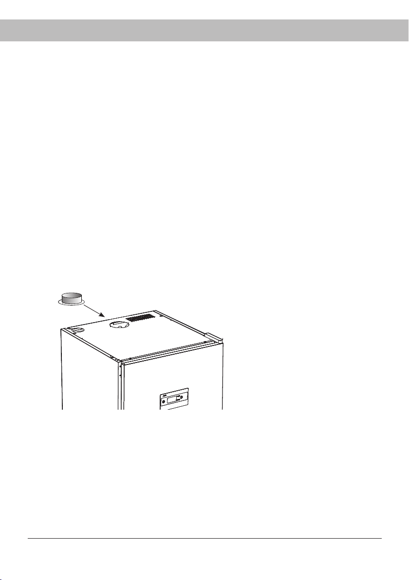
Place the supplied spigot over the hole
on the top of the cabinet, insert the
screws and secure the spigot.

1
2
3
3
2
1
18
PERMANENTLY FITTED TO MECHANICAL EXHAUST AIR VENTILATION UNIT
Air inlet
Moist air out
1. Adapter
2. Hose
3. Spigot
Air inlet
Moist air out
WITH DRAFT STABILIZER
1. Draft stabilizer
2. Flexible hose
3. Spigot
When the cabinet is permanently con-
nected to a ventilation duct, the whole
room is ventilated through the drying
cabinet.
Connect the hose to the adapter
between the hose and the ventilation
duct.
_____________________________
Adapter is not supplied.
_____________________________
_____________________________
The air inlet must not be blocked.
_____________________________
Fit the supplied hose onto the spigot. Connect the other end of the hose to the draft stabiliser
and then secure this on the exhaust vent in the room.
____________________________
The drying cabinet must not be
connected to a flue.
_____________________________
__________________________
The air inlet must not be blocked.
_____________________________

19
ELECTRICAL CONNECTION
___________________________________
The drying cabinet should be connected to
an earthed wall socket using the connecting
cable supplied and must not be permanently
wired.
___________________________________
___________________________________
The socket should be located so that the
plug can be easily pulled out if necessary.
___________________________________
___________________________________
Check that the supply current matches the
data on the rating plate and that the mains
lead is earthed correctly according to current
standard. We recommend that the power
cord be fitted with a residual current de-
vice (RCD).
___________________________________
___________________________________
The drying cabinet must be connected to a
dedicated circuit.
______________________________________
______________________________________
Do not connect the drying cabinet to the
power supply with an extension lead as the
necessary safety cannot be guaranteed (risk
of overheating).
______________________________________
___________________________________
The manufacturer disclaims all liability if the
electrical connection has not been carried
out in the way described in this use and
care manual.
______________________________________
The drying cabinet is connected to a 230 V single-phase 50-60 Hz and protectively earthed
wall socket.
Fuse 10 A.
The drying cabinet is supplied ready for connection with a cable and an earthed plug.
____________________________
CAUTION
A damaged connecting cable may only
be replaced with a special connecting
cable of the same type (can be ordered
from Asko’s spare parts department). For
safety reasons, the replacement may be
carried out only by a qualified electrician
or by Asko Service.
___________________________________

20
BEFORE USING THE DRYING CABINET
___________________________________
Read this User Manual before
starting the drying cabinet.
______________________________________
_____________________________
CAUTION
Read the safety instructions on page 4
before using the cabinet.
____________________________________
Make sure that the cabinet is fi rmly at-
tached to the wall. See page 16.
Make sure that no packaging material has
been left behind.
Use a mild detergent with hot water and
wash the inside and outside of the drying
cabinet. Dry carefully. See also the ‘Care’
section later in the manual.
21
There are three sections with hangers in the
cabinet. Each section has a number of rails
for hanging laundry.
Hang the items in the drying cabinet
according to how much space they require
- not according to their weight.
For most effi cient drying, do not lay item
fl at on the upper hanger section.
Long items of clothing closest to the
walls of the cabinet and shorter items
towards the centre of the cabinet. The
most effi cient drying results are achieved
by hanging the items in this way.
Fold up the two bottom hanger sections
if long items are to be dried.
Hang gloves, caps, scarves and similar
items on the door hangers/glove hangers
on the inside of the door.
To make it easier, extend the hanger sec-
tion when hanging laundry.
Do not overload the drying cabinet. If
you do, the laundry will become creased
and dry unevenly. Instead, leave a space
between the items of clothing if possible.
If there is a risk of particular items shedding
colour, free space should be left around
them.
Avoid drying heavy items of clothing to-
gether with lighter items as they have very
different drying times.
Do not hang knitted items. These will
stretch unnecessarily as they are heavy
when wet.
CABINET EQUIPPED WITH COAT
HANGER RACK AND SHOE RACK
For more efficient drying, hang shirts,
jackets, etc. on clothes hangers and hang
these on the clothes hanger rack.
Use the shoe rack for more effi cient drying
of shoes.
USER TIPS
Always following the laundry instructions
on the item of clothing if present.
If a fabric conditioner or anti-static agent
is used, follow the manufacturer's instruc-
tions for use of this product.
Remove laundry that it is already dry.
This will reduce drying time for remaining
laundry.
OPERATION
AIR FLOW
The illustration shows
the air fl ow in the dry-
ing cabinet.
Keep the area
around the evacu-
ation duct clear of
dust and dirt.
Make sure that the
air intake and ex-
haust duct are not
blocked.
_____________________________
NB
When the cabinet is cold it may happen
that the sealing strip of the door does not
close completely. However, this is fully
compensated when the cabinet is operat-
ing with heat as the sealing strip expands.
____________________________________
ARRANGING LAUNDRY FOR DRYING

22
DRYING PROGRAMMES
This drying cabinet is equipped with automatic programmes and manual drying programmes
for effi cient drying of fabrics of different kinds.
The automatic programmes automatically switch off the drying process when the fabrics are
dry. During the last 10 minutes, the heat is switched off while the fan cools down the fabrics
(cool-down period).
The manually time-controlled programmes stop after a set time has been counted down.
Cooling also takes place in the last 10 minutes of drying time in this case.
AUTOMATIC PROGRAMMES
Aut 40° Normal dry. Used for drying items of normal thickness.
Aut 40° Extra dry. Used for drying thicker items, deep drying.
Aut 60° Normal dry. Used for drying items of normal thickness.
Aut 60° Extra dry. Used for drying thicker items, deep drying.
40° or 60°
is selected taking account of the washing instructions for the item.
MANUAL PROGRAMMES
Man 30°. A time-controlled drying programme that should be selected for sensitive fab-
rics that should not be exposed to temperatures above 30°.
Man 40°. As above, but a somewhat higher drying temperature is allowed.
Man 60°. As above, but the fabrics can be dried at max. 60°.
Man --. This is a very energy-efficient drying programme without heat, only the fan
dries the laundry.
30°, 40° or 60°
is selected taking account of the washing instructions for the item.
_____________________________
NB
It is very important to follow the laundry
instructions for the fabrics concerned
when selecting the drying programme.
____________________________________

23
CHILD LOCK
To make sure that the drying process is not interrupted or started by mistake, a child lock func-
tion can be activated.
FUNCTION OF THE CHILD LOCK
Activation buttons must be held down for a least 3 seconds (delay time).
ACTIVATION / DEACTIVATION OF CHILD LOCK
The child lock is activated and deactivated via a setting parameter described on page 28. When
this function is activated, a clock symbol appears on the display.

24
START AUTOMATIC PROGRAMME
Start the cabinet by pressing ON/OFF.
The display lights up and shows the last programme used.
E.g. AUT 40° NormaL DRY The text fl ashes.
If this is OK - press OK and the process will then start.
- or select another programme with
UP / DOWN ARROW + OK
and the process will then start.
STARTING A MANUAL PROGRAMME
Start the cabinet by pressing ON/OFF.
The display lights up and shows the last programme used
e.g.
MAN 40° The text fl ashes.
If this is OK – press OK the default or last used drying time fl ashes,
e.g.
2:30 (two hours, 30 minutes)
If this is OK - press OK the process starts at once, in this example,
Man 40° programme where the time is count-
ed down from 2½ hours.
- or select a different drying time with
UP ARROW (increases drying time)
DOWN ARROW (reduces drying time) + OK
the process starts with a Man 40° programme
with a new drying time.
A different manual drying programme is selected in the same way as above.
If the child lock is activated, hold this button down for at least 3 seconds.
FACTORY-SET DRYING TIMES FOR MANUAL PROGRAMMES
Man 30° 2:30 (two hours, 30 minutes)
Man 40° 2:30
Man 60° 2:30

25
TIPS
If you have made a mistake or are unsure where you are, you can always press ON/OFF
and start selecting drying programme again.
If the door is open when a drying programme is started and the OK button is activated,
the display will show “close door”.
Close the door, and the selected drying programme will
start.
The animated symbol (bar) on the left side of the display indicates that the drying process
is in progress.
When the drying process has fi nished, the display shows the text
“end” (fl ashing). When
the STOP button is then pressed, or the door is opened, the current programme ends and
the display shows the last used programme.
NB: In standby mode the display goes off after 15 minutes and lights up when
any of the buttons on the control panel is activated or the door is opened.
To halt a drying process in progress, press STOP.
If the door is opened while the drying process is in progress, the fan will continue operat-
ing for another 5 minutes. The display shows
“close door” and counts down the 5 minute
programme pause period.
If the door is closed within this 5 minute period, the drying process will re-start.
If the door is left open, the drying process will stop after 5 minutes and must be restarted
manually.
If you wish to stop the drying process immediately, without a 5 minute period, press STOP.

26
SETTING DRYING PROGRAMMES
Setting to optimise the drying cabinet's automatic programme is done using the buttons on the
control panel when the drying cabinet is in programming mode.
Adjustments must be made if it is found that
the laundry does not dry suffi ciently.
the laundry is over-dried – long drying time.
PROGRAMMING MODE
1 Make sure that the ON/OFF switch on the drying cabinet is in the OFF position. The display
is unlit.
2 Hold down the UP ARROW and DOWN ARROW buttons simultaneously and press the
ON/OFF switch to the “ON” position. The display is lit and shows
“P 105” fl ashing, which
is the fi rst setting parameter in the list below. Then select the relevant parameter using the
arrow keys and confi rm with OK.
3 To return to operating mode, press DOWN ARROW and then OK.
27
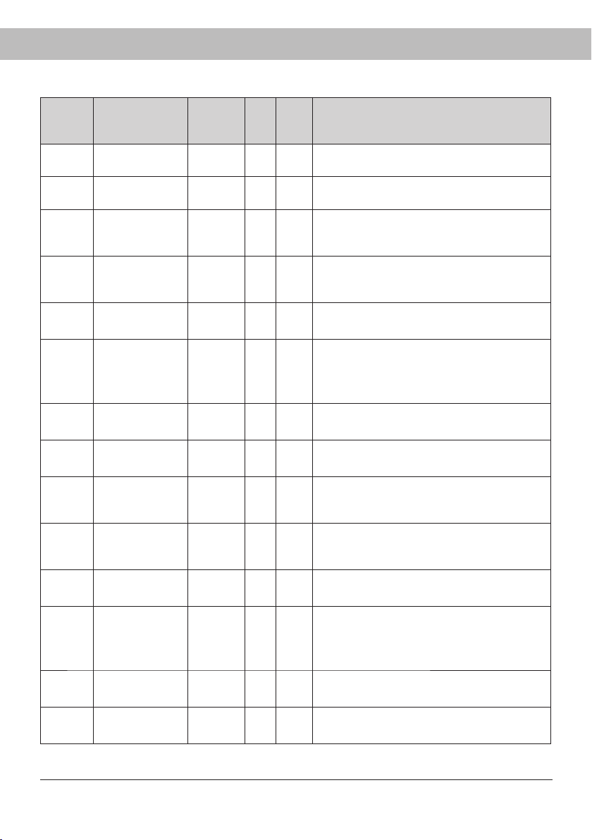
Para-
meter
Name Factory
preset
Min
va-
lue
Max
va-
lue
Signifi es
P105 Language 1 0 7 Swedish
For setting, see page 8
P115 Child lock On/Off 0 0 1 Off.
Value 1 = Child lock ON
P2011 Min drying time
Aut40°
35 (min) 10 45 Regardless of moisture level, the drying process
runs 35 min.
Factory preset.
P2012 Max drying time
Aut40°
360 (min) 60 360 Regardless of moisture level, the drying process
runs 360 min.
Factory preset.
P2013 Max temp
Aut40°
51° 41° 61° The heating elements switch off if the value is
exceeded.
P2014 Exhaust temp.
process fi nished
Aut40°
38° 34° 54° For Normal programmes the drying process
ends with cooling.
For Extra programmes the extra drying time
starts, followed by cooling.
P2015
Extra drying time
Aut40°
30 (min) 10 45 Extra programme drying time after exhaust temp.
has been reached.
P2016 Cooling time
Aut40°
10 (min) 2 20
Time when only the fan is in operation, without
heating elements. Provides more even drying time.
P2021 Min drying time
Aut60°
35 (min) 15 45 Regardless of moisture level, drying process
runs 35 min.
Factory preset.
P2022 Max drying time
Aut60°
240 (min) 60 360 Regardless of moisture level, drying process
runs 240 min.
Factory preset.
P2023 Max temp
Aut60°
90° 61° 100° The heating elements switch off if the value is
exceeded.
P2024 Outlet temp.
process fi nished
Aut60°
48° 40° 73° For Normal programmes the drying process
ends with cooling.
For Extra programmes the extra drying time
starts, followed by cooling.
P2025
Extra drying time
Aut60°
30 (min) 10 45 Extra programme drying time after exhaust temp.
has been reached.
P2026 Cooling time
Aut60°
10 (min) 2 20
Time when only the fan is in operation, without
heating elements. Provides more even drying time.
PARAMETER LIST

28
ADJUSTMENT
The programme Aut 40° Normal is controlled via temp sensor exhaust air.
The programme Aut 40° Extra is controlled via temp sensor exhaust air and a time factor.
The programme Aut 60° Normal is controlled via temp sensor exhaust air.
The programme Aut 60° Extra is controlled via temp sensor exhaust air and a time factor.
The automatic programmes end automatically when the laundry is dry.
To decide when the laundry is dry, the actual exhaust air temperature is compared against a
parameter, P2014 for 40° programme and P2024 for 60° programme.
For Aut 40° Extra an extra drying time is additionally added according to parameter P2015.
For Aut 60° Extra an extra drying time is additionally added according to parameter P2025.
It is primarily these four parameters that are adjusted to optimise the drying processes of the
automatic programmes.
Aut 40° Normal and Aut 40° Extra are adjusted with parameter P2014.
Aut 40° Extra is additionally adjusted with parameter P2015 (extra drying time).
Aut 60° Normal and Aut 60° Extra is adjusted with parameter P2024.
Aut 60° Extra is additionally adjusted with parameter P2025 (extra drying time).
If it is found that the laundry does not dry suffi ciently, the parameter value is increased.
If it is found that the laundry is over-dried, long drying time, the parameter value is reduced.
Optimisation of drying processes must always take place in small steps, start by adjusting the
parameter concerned one to two units up or down. Then check the result after the next drying
process and make any further adjustment necessary.

29
PROCEDURE
The setting parameters according to the list on pages 27 are shown on the display as follows:
on the top row of the display the relevant parameter is shown, for example P 2014,
on the bottom row the set value of the parameter is shown.
1 Go to programming mode. See page 26.
2 Browse to the relevant parameter by pressing the ARROW UP or ARROW DOWN key
repeatedly. If you go too far, simply continue browsing until the display shows the correct
parameter.
3 When the display shows the correct parameter, for example
”P 2012”, press OK to confi rm.
The row now fl ashes with the set value of the parameter.
4 Increase or reduce the value using the ARROW UP or ARROW DOWN key.
5 To save the set value, press OK.
6 To return to operating mode, press DOWN ARROW and then STOP.
RESTORING TO FACTORY SETTING
1 Go to programming mode as described on page 26.
2
Hold down the UP ARROW and DOWN ARROW keys simultaneously and press OK.
The factory settings are saved and the display shows the last run programme.
DC 7784V
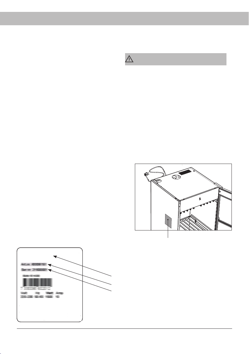
30
Name of the drying cabinet
Article number
Serial number (12 digits)
CARE
Clean the walls of the cabinet with a mild
soap solution on a damp cloth.
Dust tends to collect around the air intake
on the top of the cabinet. This can cause
disruption, in turn leading to breakdowns
in operation.
To avoid these problems, the air intake
and the roof of the cabinet should be
vacuumed at least once a year, or more
often depending on the environment the
cabinet is positioned in.
CLEANING
_______________________________
NB
Do not use high-pressure cleaning.
_______________________________________
SERVICE
Before contacting Service, you should
fi nd out the name, article number and serial
number of the drying cabinet.
This information can be found on the drying
cabinet located inside the cabinet.
Identifi cation plate
(inside)
Identifi cation plate for drying cabinet model DC7784V

31
OVERHEAT CUT-OUT
The cabinet is equipped with an overheat cut-out which is
automatically restored when the temperature in the cabinet has
fallen to an acceptable level. The time to restore varies from 10
to 15 minutes after the overheat cut-out has been activated.
When the overheat cut-out has been tripped, the cabinet
cannot be started.
If this has happened - always make a new attempt to start
after 15 minutes before reporting a fault.
If repeated breakdowns occur, contact your supplier.
32
TROUBLESHOOTING
DEAL WITH MINOR FAULTS YOURSELF
Problem What you can do
The drying cabinet is
not working
1. Check that the power lead is connected to a socket.
2. Check that no fuse has tripped
3. Have you pressed the start button?
4. Is the door closed?
The display shows an
alarm/error code
This should normally not happen, but if an alarm or error code
appears, first try to reset the alarm by holding the START/
STOP button down for 5 sec. If the problem persists, a service
technician must be called in.
Drying takes a long
time
1. Check that the correct programme has been selected for the
type of laundry.
2. Check that the laundry is not very wet (poorly spun).
3. Check that too much laundry has not been hung.
The washing does not
become dry
1. Check that the correct programme has been selected for the
type of laundry
2. Check that too much laundry has not been hung.
3. Adjust parameters 2014, 2015, 2024 and 2025 according to
the chapter “Setting of drying programme”
The sealing strip does
not close tightly/the
door is ajar
Check that the cabinet is level. Check with a spirit level, if
necessary adjust with the adjustable feet.
33
TECHNICAL DATA
MANUFACTURING STANDARD
See cabinet rating plate.
WIRING DIAGRAM
Wiring diagram can be
ordered from the manu-
facturer.
IDENTIFICATION PLATE
See page 30.
Capacity: 4 kg of laundry (cotton)
Dewatering capacity: 17 g/min
Electrical supply: Single phase 220 - 230 V, 50-60 Hz
Fuse: 10 A
Motor: 35 W
Heating element: 1500 W
Overheat cut-out: Yes
Fan capacity: 180 m³/hour
Hanging length: 16 metres
Dimensions DC7774V:
Height 1700 mm
1715 mm incl. hinge
Width 595 mm
Depth 608 mm
635 mm incl. door handle
Dimensions DC7784V:
Height 1840 mm
1855 mm incl. hinge
Width 595 mm
Depth 608 mm
635 mm incl. door handle
Weight of DC7774V ~60 kg
Weight of DC7784V: ~63 kg
Sound lavel: max 60 dB(A)
Programme Energy consumption Drying time
Aut 40° 0.60 kWh/kg laundry 2 hours 45 min
Aut 60° 0.62 kWh/kg laundry 2 hours
_______________________________________________________________
*) Stated values apply to drying cabinet connected with draft stabilizer.
Values may vary depending on spin speed
_______________________________________________________________
ENERGY CONSUMPTION AND DRYING TIMES
Drying of spun laundry *)

Doc. No: 427001038 Rev 08

ASKO DC7774V
DC7784V
www.asko.com
Right to make changes reserved.
en (02 -19)