Page 1
APPLICATION AND DESIGN GUIDELINES
Refrigerant Piping
DESIGN AND FABRICATION GUIDELINES
Corp. 9351−L9
Revised May 16, 2013
TABLE OF CONTENTS
Introduction 1......................................
Piping Limits 1.....................................
Recommended Components 3.......................
Liquid Line Quick Select 3...........................
Vapor Line Quick Select 6...........................
Long Line Requirements 6..........................
Fundamentals and Theory 7........................
Line Sizing in Detail 9..............................
System Control 21.................................
System Operation 23..............................
Appendix A 24.....................................
Appendix B — XC25 / XP25 Line Set Requirements 33.
Glossary 34.......................................
Introduction
The piping design of any air conditioning system will affect
the performance, reliability, and applied cost of that system.
The design of refrigerant piping systems involves capacity
and efficiency, reliability, oil management, refrigerant
charge, sound level, liquid refrigerant control, modulation
effectiveness and cost. Therefore it is essential that the
installing contractor understand the effect of piping and be
able to make intelligent decisions in order to do the best job
possible on the installation. This material below will clearly
explain the basic effects on system performance of the
piping design.
In most typical installations with lines less than 50 feet, the
line sizes will match up to the connections on the outdoor
unit. However, with installations involving long line sets or
elevation differences between the outdoor unit and the
indoor unit, the piping must be sized carefully. System
performance may be improved even in a typical installation
by optimizing pipe sizes.
IMPORTANT !
The intent of this manual is to represent generally
accepted safe engineering practices. Specifications
and limits outlined in this manual are subject to
change. System design should conform to all codes,
laws and regulations applying at the site at the time
of installation. Additional documents that should be
followed include The Safety Code for Mechanical
Refrigeration and the Code for Refrigeration Piping,
both available from ASHRAE. In addition, the
procedures and limits outlined in this manual do not
supersede local, state or national codes under any
circumstances.
Piping Limits
All expansion valves (TXV) listed in the following tables can
be used in either air conditioner or heat pump systems.
These TXVs incorporate a check valve for heat pump
system applications.
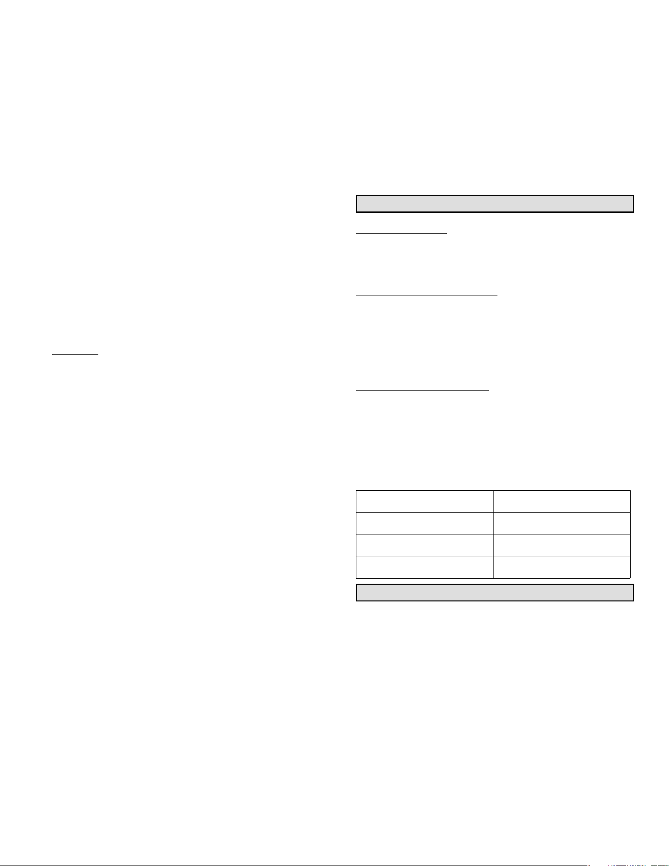
Table 1. Indoor HFC-410A —TXV
Unit Size Catalog Number
2-Ton Y0498
3-Ton Y0499
4-Ton Y0500
5-Ton Y0501
6-Ton Y0502
Table 2. Indoor HCFC-22 —TXV
Unit Size Catalog Number
2-Ton Y0512
3-Ton Y0513
4-Ton Y0514
5-Ton Y0515
6-Ton Y0516
COOLING SYSTEM
HFC-410A
S Total equivalent length = 240 feet (Piping and all
fittings, etc).
NOTE — Length is general guide. Lengths may be more or
less, depending on remaining system design factors.
S Maximum linear (actual) length = 200 feet.
S Maximum linear liquid lift = 60 feet.
NOTE —- Maximum lifts are dependent on total length,
number of elbows, etc that contribute to total pressure drop.
S Maximum length vapor riser = 125 feet.
S Up to 50 linear feet: use rated line sizes listed in unit
specifications or installation instructions.
Page 2
S If 51 to 80 linear feet: Crankcase heater required,
non-bleed port TXV (see TXV note ) preferred (RFCIV
acceptable with maximum vertical of 25 feet).
S If 81 - 200 linear feet: Crankcase heater and non-bleed
port TXV (see TXV note) required.
S Over 200 linear feet: not recommended.
TXV NOTE:
a) Indoor Factory Installed non-bleed, non-adjustable
TXV can be used on the system if it can maintain
superheat lower than 25°F at outdoor unit service
valve. Superheat is critical to compressor operating
conditions.
b) If indoor unit does not have a factory installed TXV,
or factory installed TXV needs replacing due to
system match, up or the factory TXV is not capable
of maintaining low enough superheats, use table 1
for ordering the correct TXV for specific size indoor
unit. All of these are indoor non-bleed adjustable
thermostat expansion valves. Superheat adjustment
procedures can be found in the TXV kit instruction.
S If not factory provided, high and low pressure
switches are recommended
S If not factory provided, a liquid line filter drier is
required
S For HFC-410A recommend adding oil to system
based on the amount of refrigerant charge in the
system. No need to add oil in systems with 20
pounds of refrigerant or less. For systems over 20
pounds - add one ounce of every five pounds of
refrigerant.
HCFC-22
Total equivalent length = 240 feet (Piping and all fittings,
etc).
NOTE — Length is general guide. Lengths may be more or
less, depending on remaining system design factors.
S Maximum linear (actual) length = 200 feet.
S Maximum linear liquid lift = 50 feet.
NOTE — Maximum lifts are dependent on total length,
number of elbows, etc that contribute to total pressure
drop.
S Maximum length vapor riser = 125 feet.
S Up to 50 linear feet: use rated line sizes listed in unit
specifications or installation instructions.
S If 51 to 80 linear feet: Crankcase heater required,
non-bleed port TXV (see TXV note) preferred (RFCIV
acceptable with maximum vertical of 25 feet).
S If 81 - 200 linear feet: Crankcase heater and non-bleed
port TXV (see TXV note below) required.
S Over 200 linear feet: not recommended.
TXV NOTE:
a) Indoor Factory Installed non-bleed, non-adjustable
TXV can be used on the system if it can maintain
superheat lower than 25°F at outdoor unit service
valve. (Superheat is critical to compressor operating
conditions)
b) If indoor unit does not have a factory installed TXV,
or factory installed TXV needs replacing due to
system match, up or the factory TXV is not capable
of maintaining low enough superheats, use table 2
for ordering the correct TXV for specific size indoor
unit. All of these are indoor non-bleed adjustable
thermostat expansion valves. Superheat adjustment
procedures can be found in the TXV kit instructions.
S If not factory provided, high and low pressure
switches are recommended
S If not factory provided, a liquid line filter drier is
required
S For HFC-22 systems with suction lines over 50 feet
with lines that are 7/8” or smaller, add three ounces
of oil every 10 feet of line over 50 feet. For systems
with 1-1/8” and larger suction lines, add four ounces
of oil every 10 feet of line over 50 feet.
HEAT PUMP SYSTEM
HFC-410A
S Total equivalent length = 240 feet (Piping and all
fittings, etc)
NOTE — Length is general guide. Lengths may be more or
less, depending on remaining system design factors.
S Maximum linear (actual) length = 200 feet.
S Maximum linear liquid lift = 60 feet.
NOTE — Maximum lifts are dependent on total length,
number of elbows, etc that contribute to total pressure drop
plus when the outdoor unit is above the indoor unit.
S Maximum length vapor riser = 60 feet.
S Up to 50 linear feet: use rated line sizes listed in unit
specifications or installation instructions.
S If 51 to 200 linear feet: Crankcase heater required,
non-bleed port TXV (see TXV note) required.
S If 81 - 200 linear feet: Crankcase heater and non-bleed
port TXV (see TXV note below) required.
S Over 200 linear feet: not recommended.
TXV NOTE:
a) Indoor Factory Installed non-bleed, non-adjustable
TXV can be used on the system if it can maintain
superheat lower than 25°F at outdoor unit service
valve. Superheat is critical to compressor operating
conditions.
Page 3
b) If indoor unit does not have a factory installed TXV,
or factory installed TXV needs replacing due to
system match, up or the factory TXV is not capable
of maintaining low enough superheats, use table 1
for ordering the correct TXV for specific size indoor
unit. All of these are indoor non-bleed adjustable
thermostat check expansion valves. Superheat
adjustment procedures can be found in the TXV kit
instructions.
S If not factory provided, high and low pressure
switches are recommended. Low pressure switch
bypass switch will be required on units that do not
have provision to ignore the switch when unit is
operating in ambient temperatures below 15°F.
S If not factory provided, a liquid line filter drier is
required.
S For HFC-410A recommend adding oil to system
based on the amount of refrigerant charge in the
system. No need to add oil in systems with 20
pounds of refrigerant or less. For systems over 20
pounds - add one ounce of every five pounds of
refrigerant.
HCFC-22
S Total equivalent length = 180 feet (Piping and all
fittings, etc).
NOTE — Length is general guide. Lengths may be more or
less, depending on remaining system design factors.
S Maximum linear (actual) length = 150 feet.
S Maximum linear liquid lift = 50 feet.
NOTE — Maximum lifts are dependent on total length,
number of elbows, etc that contribute to total pressure drop
plus when the outdoor unit is above the indoor unit.
S Maximum length vapor riser = 50 feet.
S Up to 50 linear feet: use rated line sizes listed in unit
specifications or installation instructions.
S If 51 to 150 linear feet: Crankcase heater required,
non-bleed port TXV (see TXV note below) required.
S If 81 - 200 linear feet: Crankcase heater and non-bleed
port TXV (see TXV note) required.
S Over 150 linear feet: not recommended.
TXV NOTE:
a) Indoor Factory Installed non-bleed, non-adjustable
TXV can be used on the system if it can maintain
superheat lower than 25°F at outdoor unit service
valve. (Superheat is critical to compressor operating
conditions)
b) If indoor unit does not have a factory installed TXV,
or factory installed TXV needs replacing due to
system match, up or the factory TXV is not capable
of maintaining low enough superheats, use table 2
for ordering the correct TXV for specific size indoor
unit. All of these are indoor non-bleed adjustable
thermostat check expansion valves. Superheat
adjustment procedures can be found in the TXV kit
instructions.
S If not factory provided, high and low pressure
switches are recommended. Low pressure switch
bypass switch will be required on units that do not
have provision to ignore the switch when unit is
operating in ambient temperatures below 15°F.
S If not factory provided, a liquid line filter drier is
required.
S For HFC-22 systems with suction lines over 50 feet
with lines that are 7/8” or smaller, add three ounces
of oil every 10 feet of line over 50 feet. For systems
with 1-1/8” and larger suction lines, add four ounces
of oil every 10 feet of line over 50 feet.
Recommend Components
PRESSURE TAPS
Should be installed at the inlet and outlets of indoor coils to
allow field measurement of saturated pressures for
calculating superheats and sub-cooling values.
ANTI-SHORT PROTECTION
Systems should have anti-short cycle.
S ON - usually four minutes.
S Timed OFF - usually five minutes and timer
NOTE — A number of electronic thermostats contain these
features)
OPTIONAL SIGHT GLASS
A glass window type device placed in a liquid line and used
for visual inspection of the liquid. It can also be used to
determine the point at which all gas bubbles are removed
from liquid line. A sight glass is not a good indicator of
sub-cooling and cannot be used to determine charge.
Optional Sight Glass Catalog Numbers are listed in table 3.
Table 3. Sight Glass Catalog Numbers
Liquid Line Size
Catalog Number
3/8” 57K19
1/2” 19B62
5/8” 19B63
Liquid Line Quick Select
Table 4 should be used to size the liquid line when there is a
liquid lift. Follow this procedure for sizing the liquid line:
1. Find your unit on the left side of table 4.
2. Start with the rated liquid line size on the outdoor unit
(refer to engineering handbook or installation
instructions)
3. Read over to the linear length shown at the top of table
4.
4. Does maximum elevation meet your needs? If yes, use
this size liquid line.
5. If not, consider the larger line size shown in table 4.
For variable capacity systems see section Line Sizing in
Detail.
Table 4 simplifies liquid line selection by incorporating all of
the calculations involving liquid line sizing, pressure drop,
velocity range and tonnage.
Page 4
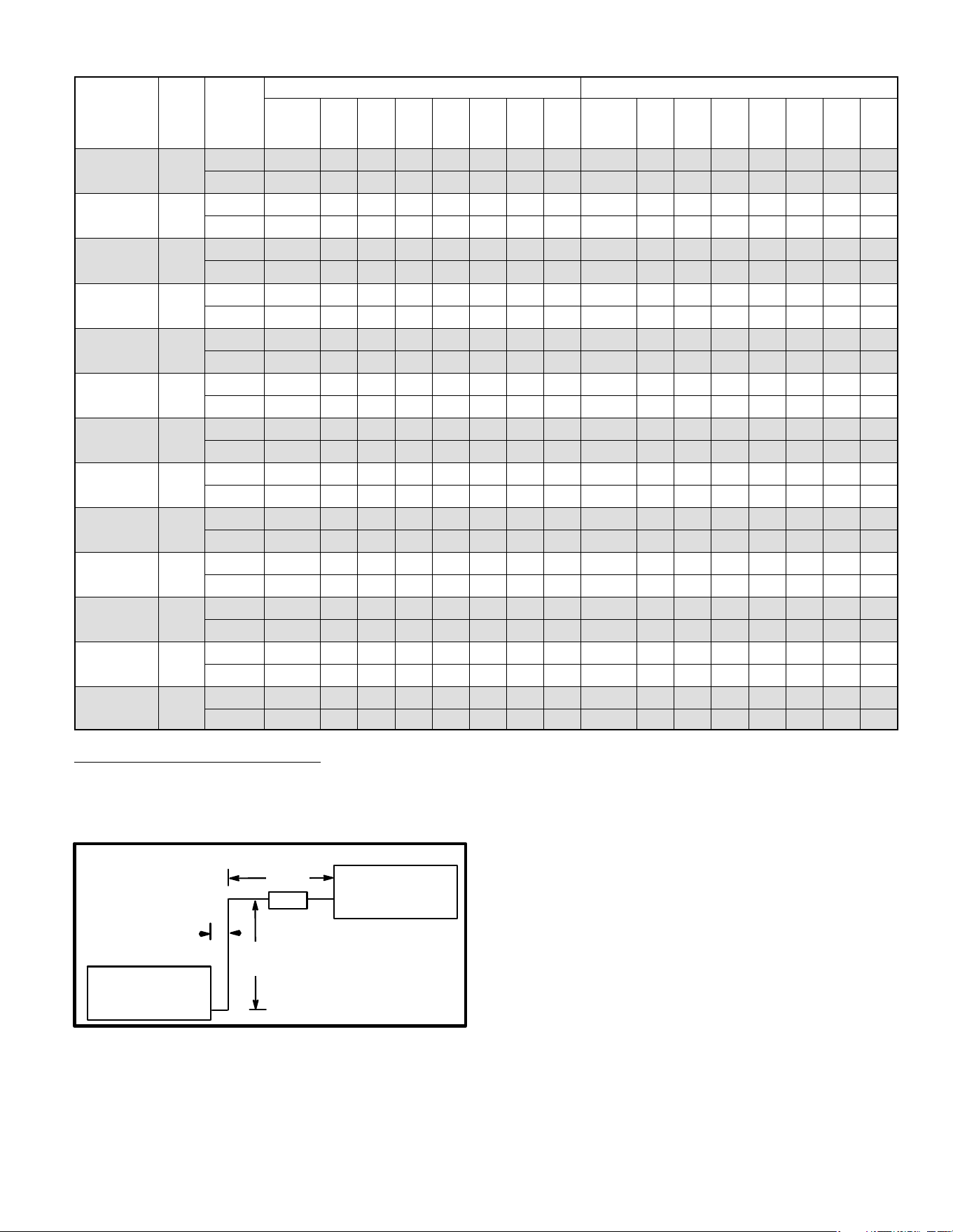
Table 4. Liquid Line Quick Select
UNIT
UNIT
TONS
LINE
SIZE
HCFC-22 HFC-410A
UP TO
25
FEET
50 75 100 125 150 175 200
UP TO
25
FEET
50 75 100 125 150 175 200
012 1
5/16” 25 50 50 50 50 49 47 45 25 50 60 60 60 60 60 60
3/8” 25 50 50 50 50 50 50 50 25 50 60 60 60 60 60 60
018 1.5
5/16” 25 50 48 44 41 37 33 29 25 50 60 60 55 51 46 42
3/8” 25 50 50 50 50 50 50 49 25 50 60 60 60 60 60 60
024 2
5/16” 25 47 41 34 28 21 15 8 25 50 55 48 40 33 25 18
3/8” 25 50 50 50 50 46 44 42 25 50 60 60 60 60 59 57
030 2.5
5/16” 25 45 38 30 23 15 8 NR 25 50 52 43 35 26 17 8
3/8” 25 50 50 46 43 39 36 32 25 50 60 60 58 54 50 46
036 3
3/8” 25 50 46 41 36 32 27 22 25 50 60 56 51 45 39 34
1/2” 25 50 50 50 50 50 50 50 25 50 60 60 60 60 60 60
042 3.5
3/8” 25 47 41 34 28 22 15 9 25 50 56 48 41 33 26 19
1/2” 25 50 50 50 50 50 50 48 25 50 60 60 60 60 60 60
048 4
3/8” 25 44 36 28 20 12 4 NR 25 50 50 41 31 22 13 NR
1/2” 25 50 50 50 50 49 47 45 25 50 60 60 60 60 60 60
060 5
3/8” 25 36 24 12 NR NR NR NR 25 50 36 22 8 NR NR NR
1/2” 25 50 50 49 47 44 41 38 25 50 60 60 60 59 56 53
072 6
1/2” 25 50 49 46 42 38 35 31 25 50 60 60 57 53 49 45
5/8” 25 50 50 50 50 50 50 50 25 50 60 60 60 60 60 60
090 7.5
5/8” 25 50 50 50 50 50 50 48 25 50 60 60 60 60 60 60
3/4” 25 50 50 50 50 50 50 50 25 50 60 60 60 60 60 60
120 10
5/8” 25 50 50 50 47 45 42 40 25 50 60 60 60 60 57 54
3/4” 25 50 50 50 50 50 50 50 25 50 60 60 60 60 60 60
180
(2-COMP)
15
5/8” X 2 25 50 50 50 50 50 50 48 25 50 60 60 60 60 60 60
3/4” X 2 25 50 50 50 50 50 50 50 25 50 60 60 60 60 60 60
240
(2-COMP)
20
5/8” X 2 25 50 50 50 47 45 42 40 25 50 60 60 60 60 57 54
3/4” X 2 25 50 50 50 50 50 50 50 25 50 60 60 60 60 60 60
EXAMPLE 1: LIQUID LINE SIZING
Given: 10-ton, HCFC-22 A/C cooling only condensing unit
on ground level with a 10 ton evaporator on the third level
above ground (40 feet elevation) and a total of 100 feet
(linear) of piping (see figure 1).
10-TON
CONDENSING
UNIT
10-TON
EVAPORATOR
UNIT
67
FEET
3 FEET
40
FEET
Figure 1. Liquid Line Sizing Example
Find: Select liquid line size from table 4.
Solution:
Find the 10-ton unit on the left side. Start with the 5/8” liquid
line size which is the rated liquid line size listed in the
engineering handbook. Read over to 100 feet of linear
length.
50 feet of elevation is allowed for this liquid line size, so this
meets the 40 foot requirement in this installation. If it did not
meet your requirements, you would need to consider a
larger liquid line listed for the 10 ton unit in table 4.
Page 5
Table 5 – HCFC-22 and HFC-410A Vapor Lines
UNIT
UNIT
TONS
SUCTION /
VAPOR LINE
SIZE
HCFC-22
PRESSURE
DROP PSI/100
FEET
HFC-410A
PRESSURE
DROP PSI/100
fEET
PREFERRED FOR
VERTICAL
VAPOR RISES
PREFERRED FOR
HORIZONTAL
RUNS
012 1
1/2” 13.0 7.8 X
5/8” 3.1 1.9 X
018 1.5
5/8” 6.5 3.9 X
3/4” 2.4 1.4 X
024 2
5/8” 12.0 7.2 X
3/4” 4.2 2.5 X
030 2.5
3/4” 6.0 3.6 X
7/8” 3.1 1.9 X
036 3
3/4” 8.5 5.1 X
7/8” 4.6 2.8 X
042 3.5
7/8” 5.9 3.5 X
1-1/8” 1.4 0.8 X
048 4
7/8” 7.8 4.7 X
1-1/8” 1.9 1.1 X
060 5
7/8” 12.0 7.2 X
1-1/8” 2.8 1.7 X
072 6
1-1/8” 4.0 2.4 X
1-3/8” 1.4 0.8 X
090 7.5
1-3/8” 2.0 1.2 X
1-5/8” 0.9 0.5 X
120 10
1-3/8” 2.4 1.4 X
1-5/8” 1.4 0.8 X
180 (2-COMP) 15
1-3/8” X 2 2.0 1.2 X
1-5/8” X 2 0.9 0.5 X
240 (2-COMP) 20
1-3/8” X 2 2.4 1.4 X
1-5/8” X 2 1.4 0.8 X
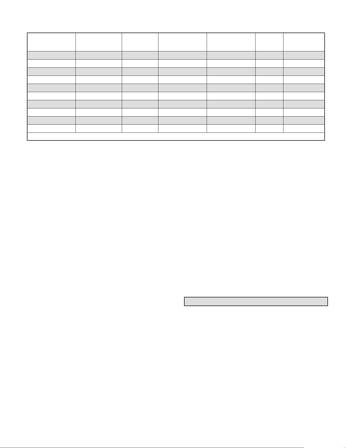
Table 6. Desirable Characteristics
Key System Consideration Desirable Characteristic Piping System Impact
Reliability Long Compressor Life
Poor oil management may shorten the life of the compressor.
Proper liquid refrigerant control is essential.
Performance
High Capacity
High energy efficiency
Effective Modulation
Low Sound Levels
Pressure drop in Refrigerant lines tends to decrease capacity and
increase power consumption.
High velocities can increase sound levels. Modulation often
depends on proper piping.
Cost Low Applied Cost
Amount of refrigerant charge, copper piping, accessories, and labor
used will impact the applied cost.
Page 6
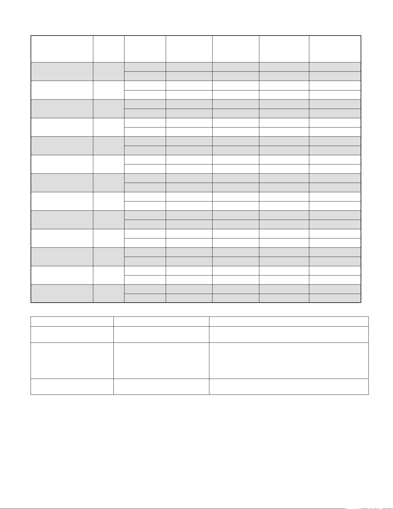
Table 7. BTUH Loss For Equivalent Length (HFC-410A)
Nominal
Tons
Tubing
Outside
Diameter
(Inches)
BTUH Loss For Equivalent Length (HFC-410A)
25' 50' 75' 100' 125' 150' 175' 200'
2
5/8 -100 -275 -460 -667 -846 -1014 -1268 -1487
3/4 0 -77 -169 -277 -384 -478 -602 -726
7/8 46 0 -57 -130 -196 -265 -360 -487
3
3/4 -89 -270 -452 -652 -839 -1071 -1354 -1564
7/8 0 -93 -167 -274 -407 -563 -742 -953
1 1/8 52 13 -11 -74 -188 -318 -441 -611
4
3/4 -208 -575 -918 -1356 -1613 -2026 -2429 -2824
7/8 0 -168 -320 -528 -726 -896 -1162 -1348
1 1/8 114 80 19 -58 -148 -266 -391 -537
5
7/8 -221 -598 -948 -1305 -1716 -2063 -2438 -2844
1 1/8 0 -109 -239 -398 -565 -741 -925 -1106
1 3/8 52 -33 -133 -239 -339 -478 -572 -775
Vapor Line Quick Select
Table 2 should be used to size the vapor line. Follow this
procedure for sizing the vapor line:
1. Find your unit on the left side of table 2 (for both
HCFC-22 and HFC-410A)
2. Start with the rated vapor line size on the outdoor unit
(refer to engineering handbook or installation
instructions)
3. You may consider increasing or decreasing the vapor
line size if a larger size is listed in table 2. Larger vapor
lines will reduce pressure drop and improve system
efficiency. For details see section Line Sizing in Detail.
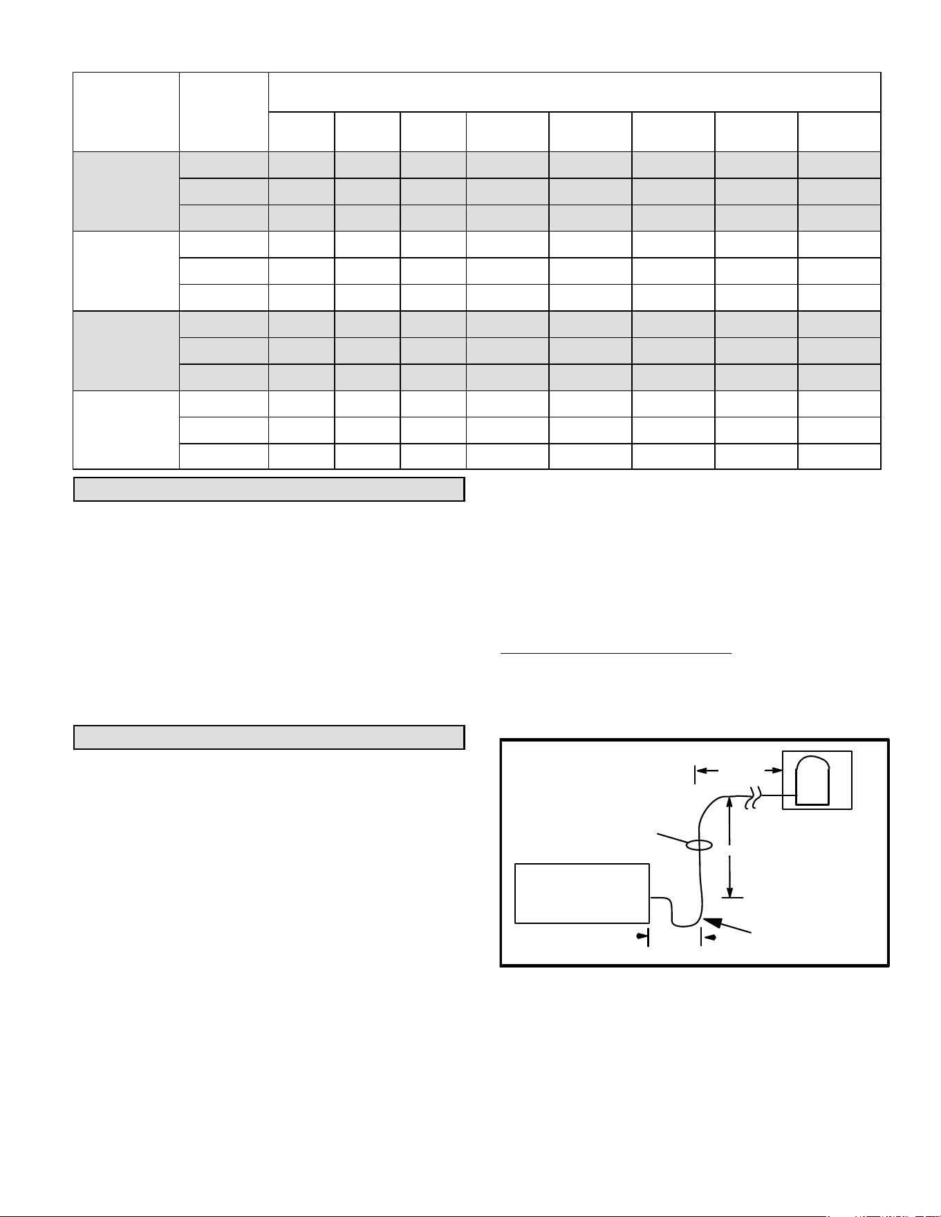
Long Line Requirements
For systems with the outdoor unit 5-50 feet above the
indoor unit, one trap must be installed at the bottom of the
suction riser. For suction lifts between 50 and 100 feet
(cooling only units; vapor lifts over 50 feet not allowed on
heat pump), install a second trap halfway up the riser. For
suction lifts over 100 feet, install traps at 1/3 intervals.
For variable capacity systems see section Line Sizing in
Detail.
COMBINATION VAPOR LINES
Vapor risers must be sized to ensure adequate velocity for
oil return. In general, piping can be designed to ensure
adequate velocities for oil return even with two stage
systems. A good way to do this is to reduce the vapor riser
size. A combination vapor line can be constructed with the
larger diameter pipe in the horizontal runs to minimize
pressure drop, and smaller diameter pipe in the vertical to
increase velocities.
NOTE — Maximum vapor riser = 125 feet
Table 5 simplifies vapor/suction line selection by
incorporating all of the calculations involving vapor line
sizing, pressure drop, velocity range and tonnage. To
calculate capacity loss due to pressure drop in the vapor
line refer to the section Sizing Suction and Vapor Lines in
this document.
Assumptions: 2-4 elbows every 50 feet
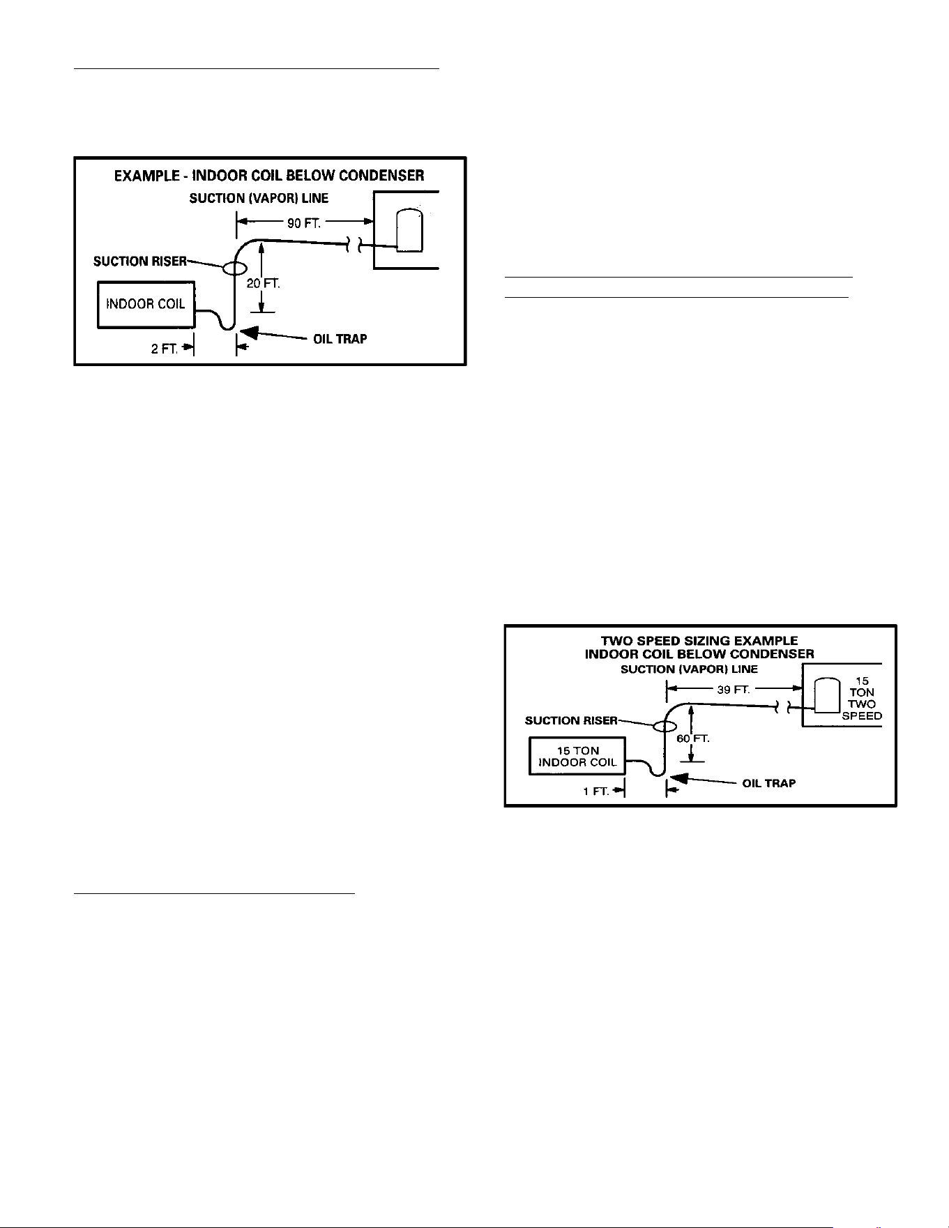
EXAMPLE: VAPOR LINE SIZING
Given: 7-1/2 ton HCFC-22 A/C cooling only condensing
unit with evaporator lower than condenser, with 112 feet of
piping. The piping includes 20 feet of vertical lift and 92 feet
of horizontal run as illustrated in figure 2.
INDOOR COIL
SUCTION RISER
90 FT.
2 FT.
40 FT.
OIL TRAP
Figure 2. Indoor Coil Below Condenser
Find: Select vapor line size from table 5.
Solution: 1-3/8 inch outside diameter line is the rated
suction line size. It is listed on table 5 because it will provide
good refrigerant velocities for oil return.
Page 7
Table 8. Equivalent Length in Feet of Straight Pipe for Valves and Fittings
LINE SIZE
(OUTSIDE
DIAMETER) INCH
SOLENOID
/GLOBAL GLOBE
VALVE
ANGLE VALVE
90º LONG* RADIUS
ELBOW
45º LONG* RADIUS
ELBOW
TEE LINE TEE BRANCH
3/8 7 4 0.8 0.3 0.5 1.5
1/2 9 5 0.9 0.4 0.6 2.0
5/8 12 6 1.0 0.5 0.8 2.5
3/4 14 7 1.3 0.6 0.9 3.0
7/8 15 8 1.5 0.7 1.0 3.5
1-1/8 22 12 1.8 0.9 1.5 4.5
1-3/8 28 15 2.4 1.2 1.8 6.0
1-5/8 35 17 2.8 1.4 2.0 7.0
2-1/8 45 22 3.9 1.8 3.0 10
2-5/8 51 26 4.6 2.2 3.5 12
* Long radius elbow. Multiply factor by 1.5 for short radius elbow equivalent length.
Table 5 shows that a larger suction line size is available for
this system. You may consider increasing the horizontal
vapor line size to 1-5/8”. This larger horizontal vapor line will
reduce pressure drop and improve system efficiency. The
larger vapor size is not advisable for the vertical vapor rise.
Consult the section Line Sizing in Detail for exact velocity
and pressure drop calculations.
ADDITIONAL REQUIREMENTS FOR AIR
CONDITIONER SYSTEMS
Applications with less than 50 linear feet of refrigerant line
may use fixed RFC metering devices on approved
matchups as listed in engineering handbook. Plans with
less than 50 linear feet of line and less than 20 feet of lift
may also use OEM pre-fabricated line sets if available as
listed in engineering handbook.
In applications where cooling operation below 50 F is
anticipated and an economizer is not being used, low
ambient (head pressure) controls must be installed. See
Low ambient section in Appendix.
ADDITIONAL REQUIREMENTS FOR HEAT PUMP
SYSTEMS
Some OEM equipment is equipped with a factory installed
accumulator. Never add a second accumulator. If an
accumulator is not supplied and one must be added, the
accumulator must be properly sized and must be located in
the suction line between the reversing valve and the
compressor.
OEM heat pump units are factory equipped with a liquid line
filter drier. Never install a liquid line filter drier in addition to
factory installed driers due to risk of excess pressure drop
and risk of improper installation. A bi-flow drier should be
used with heat pump systems.
Special consideration must be given to heat pump systems
when there is a difference in elevation between the outdoor
and indoor units. Due to the reversal of refrigerant flow from
heating to cooling cycle, there is always a liquid and suction
lift to consider when sizing the refrigerant lines.
Maximum liquid lift should not exceed 50 linear feet for
HCFC-22, or 60 linear feet for HFC-410A. Additional
pressure drop due to friction will result in total pressure drop
approaching the 30 psi maximum that could produce
flashing in HCFC-22 systems (35 psi in HFC-410A
systems).
Likewise, maximum suction lift must not exceed 50 feet for
HCFC-22 or 60 feet for HFC-410A due to limitations placed
on the liquid line. (When refrigerant flow is reversed, a liquid
drop will become a liquid lift). The vapor line must be sized
as a suction riser with adequate velocity for oil return if there
is any difference in elevation between the indoor and
outdoor units.
In applications where cooling operation below 50 F is
anticipated and an economizer is not being used, low
ambient (head pressure) controls must be installed.
Solenoid valves are uni-directional devices. Since solenoid
valves are uni-directional, they are seldom used on heat
pump systems. If used, they require a check valve to
bypass refrigerant around the solenoid during the heating
cycle. Never install a pump-down cycle on a heat pump
system.
Fundamentals and Theory
The three prime considerations when designing a
refrigerant piping scheme are:
1. System reliability
2. System performance
3. Cost
The desirable characteristics of any air conditioning system
are described in table 8:
There are a number of ways that the piping system design
can affect compressor reliability. Many compressors are
susceptible to refrigerant slugging and oil dilution.
Oversized liquid lines increase the amount of refrigerant in
a system which creates the potential for these problems.
Undersized liquid lines can also create problems.
Undersized liquid lines can cause refrigerant to flash before
the expansion device. The result of a starved evaporator in
this situation can be loss of capacity, evaporator coil
frosting, or high superheat.
Page 8
Suction lines and vapor lines must also be carefully sized.
Oversized suction lines may result in refrigerant velocities
being too low to return oil to the compressor. Undersized
suction lines reduce capacity, cause increased refrigerant
velocity sound and cause high superheat.
Long refrigerant lines have to be carefully planned.
Excessive line length can reduce system capacity and lead
to reliability problems.
The largest penalty for pressure drop is in the suction line.
An acceptable pressure drop in the suction line is 3 PSI with
HCFC-22 and 5 PSI with HFC-410A. In very long runs
pressure drop can exceed these values. However, the most
important function of the suction line is oil return, so in very
long runs the higher pressure drop may be necessary.
The most important function of the liquid line is to deliver a
solid column of 100% liquid refrigerant to the expansion
device. Liquid lines are kept small to reduce the amount of
system charge. As long as the pressure drop in the liquid
line does not cause the refrigerant to flash, the liquid line
diameter can be kept small. Adequate subcooling
guarantees that the expansion device will see 100% liquid
refrigerant.
Any pressure drop in the liquid line due to vertical lift must
also be taken into consideration. This pressure drop should
be added to the friction loss in the liquid line to figure the
total pressure drop of the liquid line. The maximum
acceptable pressure drop in the liquid line is 30 PSI for
HCFC-22 and 35 psi for HFC-410A.
In order to keep installed cost down, the contractor should
use the smallest possible tubing that will yield acceptable
friction losses in the system.
OIL MANAGEMENT
Small amounts of oil from the compressor are constantly
being circulating with the refrigerant throughout the system.
This oil must be returned to the compressor for proper
lubrication of bearings and contact surfaces. Suction and
vapor lines must be sized carefully to eliminate oil
management problems.
For systems with the outdoor unit 5-50 feet above the
indoor unit, one trap must be installed at the bottom of the
suction riser. For suction lifts between 50 and 100 feet
(cooling only units; vapor lifts over 50 feet not allowed on
heat pump), install a second trap halfway up the riser. For
suction lifts over 100 feet, install traps at 1/3 intervals.
Oil return is a major consideration since some oil is
continually being circulated with the refrigerant. Oil must be
returned to the compressor by entrainment with the
refrigerant vapor. Minimum velocity must be approximately
800 feet per minute (fpm) in horizontal runs, and
approximately1200 fpm in vertical suction risers.
HCFC-22
Lines over 50 feet and with suction line 7/8 inch outside
diameter or smaller, add three ounces of oil for each 10 feet
of line over 50 feet. For systems with 1-1/8 inch outside
diameter and larger suction lines, add four ounces of oil for
each 10 feet of line above 50 feet. Consult the OEM
engineering handbook or installation instructions for proper
oil type.
HFC-410A
Recommend adding oil to system based on the amount of
refrigerant charge in the system. No need to add oil in
systems with 20 pounds of refrigerant or less. For systems
over 20 pounds - add one ounce of every five pounds of
refrigerant.
EQUIVALENT LENGTH
Each valve, fitting, and bend contributes to friction pressure
drop because of the interruption of smooth flow. Because it
can be difficult to calculate the pressure drop of each fitting
it is more useful to use equate the pressure drop to an
equivalent length of straight tubing for each fitting. This
makes it easier to add up the entire length of line, including
fittings and valves, as an equivalent length of straight pipe.
Pressure drop and line sizing tables are set up on the basis
of pressure drop per 100 feet of straight pipe. The
equivalent length of copper tubing for commonly used
valves and fittings can be found in table 8.
PRESSURE DROP
Refrigerant piping involves complex relationships in the
flow of refrigerant and oil. The flow of refrigerant involves
the interaction of many factors, including velocity, pressure,
friction, density, viscosity and the work required to force the
flow. The nature of refrigerant flow is well understood
because of practical experience. Any flow through a pipe
leads to pressure drop or friction losses. The smaller the
pipe the higher the pressure drop. Table NO TAG generally
explains the effect of pressure drop in a refrigerant piping
system.
Table 9. Location of Pressure Drop
Location of
Pressure Drop
Affect On System Performance
Suction Line
Significantly reduces system ca
pacity and efficiency
Hot Gas Lines
Reduces system capacity and ef
ficiency
Liquid Line
No penalty on system perfor
mance as long as there is a solid
column of liquid at the expansion
device
Pressure drop is important from a performance standpoint.
The following general statements point out the effects of
pressure drop in the various components of the
refrigeration piping system.
1. Pressure drop in the suction line reduces capacity and
increases power consumption. For air conditioning
systems, a one pound drop in the suction line reduces
capacity approximately one percent. A suction line
pressure drop of up to thee psi for HCFC-22 (five psi for
HFC-410A) is generally acceptable.
Page 9
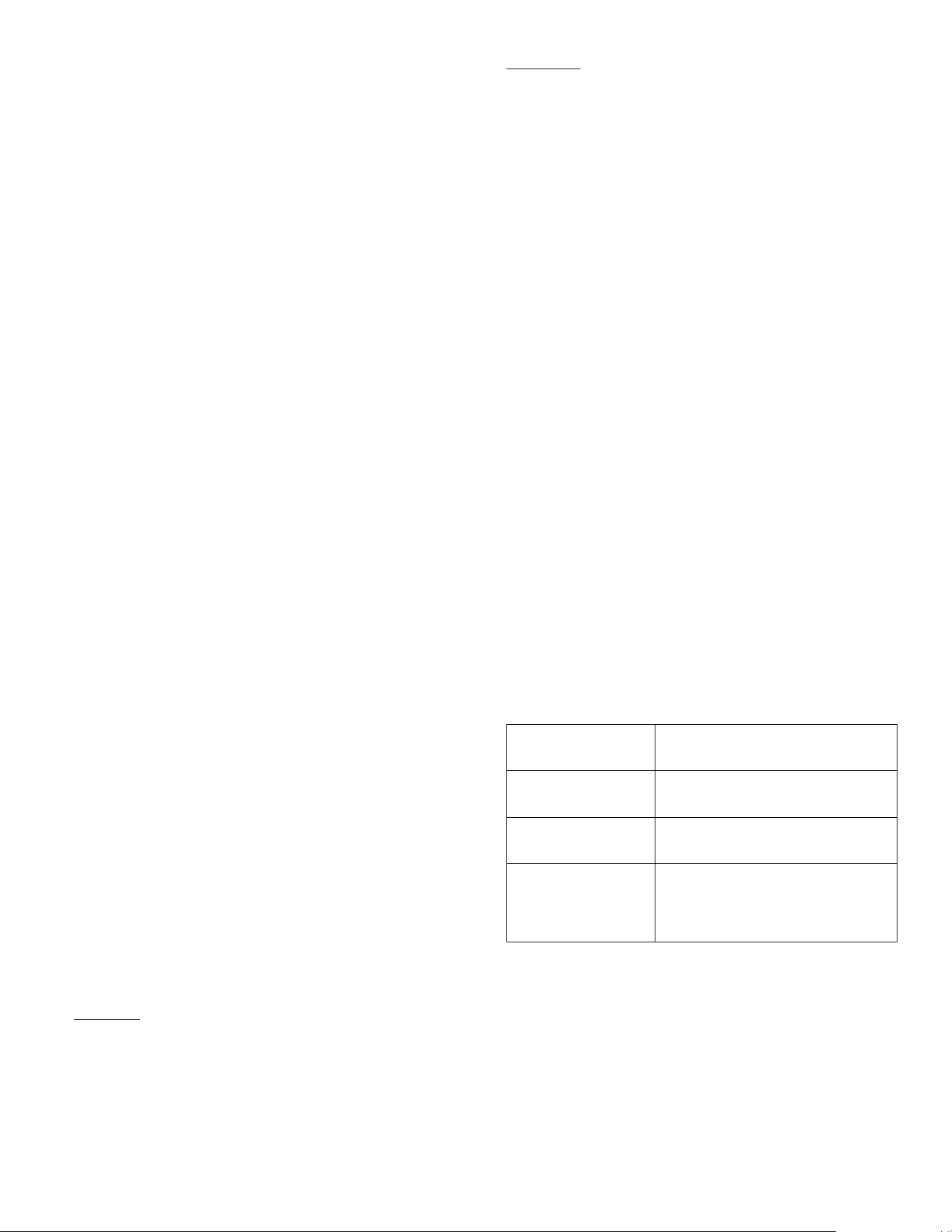
Table 10. Refrigerant Charge (Pounds) in 100 feet of Type L Copper Tubing
Line
Size
3/8” 1/2” 5/8” 5/8” 3/4” 3/4” 7/8” 7/8” 1-1/8” 1-3/8” 1-5/8” 2-1/8
Liquid Liquid Liquid Suction Liquid Suction Liquid Suction Suction Suction Suction Suction
HCFC−22 3.8 7.0 11.3 0.3 16.8 0.4 23.4 0.6 1.0 1.6 2.2 3.9
HFC−410A 3.1 5.8 9.2 0.4 13.8 0.6 19.2 0.8 1.3 2.0 2.9 5.0
2. Pressure drop in the liquid line produces no significant
capacity loss as long as 100% liquid is delivered to the
expansion valve and the pressure available is
adequate to produce the required flow. Pressure drop
due to lift must be added to the friction losses to
determine total pressure drop. At normal liquid
temperatures, HCFC-22 pressure drops 0.5 psi per
foot of vertical liquid lift. HFC-410A pressure drops 0.43
psi per foot of vertical liquid lift.
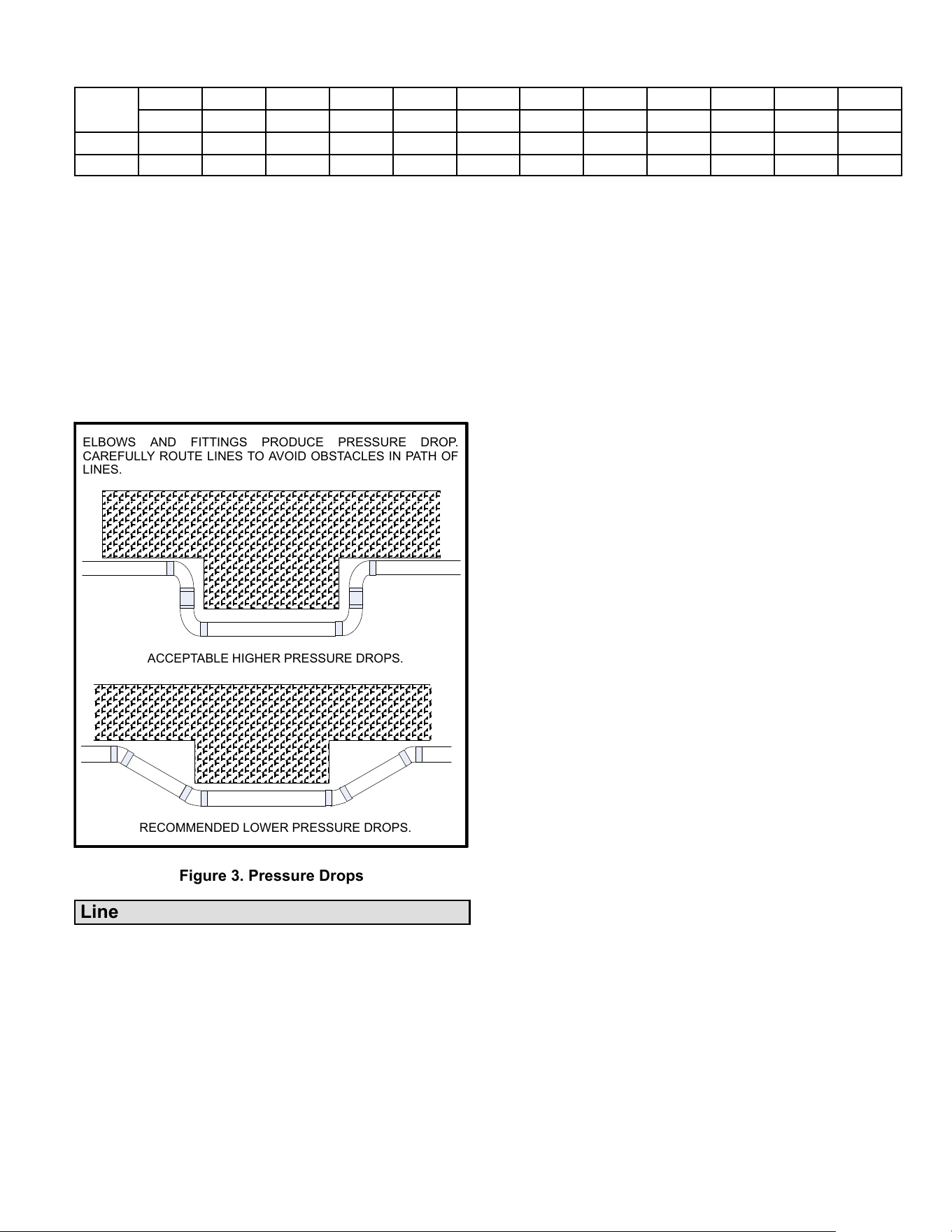
One contributor to pressure loss in refrigerant lines is
elbows and fittings. Figure 3 illustrates how lines can be run
to avoid pressure losses.
ÄÄÄÄÄÄÄÄÄÄÄÄÄÄÄ
ÄÄÄÄÄÄÄÄÄÄÄÄÄÄÄ
ÄÄÄÄÄÄÄÄÄÄÄÄÄÄÄ
ÄÄÄÄÄÄÄÄÄÄÄÄÄÄÄ
ÄÄÄÄÄÄÄÄÄÄÄÄÄÄÄ
ÄÄÄÄÄÄÄÄÄÄÄÄÄÄÄ
ÄÄ
ÄÄ
ÄÄ
ÄÄ
ÄÄ
ÄÄ
ÄÄ
ÄÄ
ÄÄÄÄÄÄÄÄÄÄÄÄÄÄÄ
ÄÄÄÄÄÄÄÄÄÄÄÄÄÄÄ
ÄÄÄÄÄÄÄÄÄÄÄÄÄÄÄ
ÄÄÄÄÄÄÄÄÄÄÄÄÄÄÄ
ÄÄÄÄÄÄÄÄÄÄÄÄÄÄÄ
ÄÄ
ÄÄ
ÄÄ
ÄÄ
ÄÄ
ÄÄ
ELBOWS AND FITTINGS PRODUCE PRESSURE DROP.
CAREFULLY ROUTE LINES TO AVOID OBSTACLES IN PATH OF
LINES.
ACCEPTABLE HIGHER PRESSURE DROPS.
RECOMMENDED LOWER PRESSURE DROPS.
Figure 3. Pressure Drops
Line Sizing in Detail
The first step in the design of a piping system is to layout the
entire system (i.e. relative location of the condensing unit
and the evaporator, length of each segment of the piping
system, length of suction risers and liquid risers etc). Start
by making a sketch of the system including lengths of pipe,
number of elbows, tees, valves, and any other irregular
piping and fittings needed. This information will be used to
determine total equivalent length for calculating pressure
drop due to friction.
The same methods apply to both A/C and heat pump
systems. A suction line sized to produce adequate velocity
for oil entrainment and pressure drop with minimum
capacity reduction will function properly as a hot gas
discharge line during a heating cycle. Also, if there is a
vertical difference in height between the outdoor and indoor
units, there is always a vapor and liquid lift to consider in
sizing due to the reversal of refrigerant flow.
OEM split system condensing units and heat pumps (four
tons and under) match with line sets of varying lengths of up
to 50 feet (linear). These applications offer quick and simple
installations that are trouble free if the line sets are properly
installed. On split commercial applications and residential
installations beyond 50 feet, special design considerations
must be followed to assure satisfactory system
performance. An improperly designed system could result
in a serious loss of capacity or even compressor failure.
The purpose of the liquid line is to convey a full column of
100% liquid from the condenser to the metering device at
the evaporator without flashing. The amount of liquid line
pressure drop which can be tolerated is dependent on the
number of degrees of liquid subcooling leaving the
condenser and the saturated condensing temperature. If
the condensing temperature and subcooling are known,
the maximum allowable pressure drop can be calculated.
All OEM equipment is designed so that the charge may be
adjusted to provide adequate subcooling leaving the
outdoor unit. This will allow a 30 pound drop in the
HCFC-22 liquid line (including pressure drop due to friction
loss and vertical lift) and 35 psi in the HFC-410A liquid line.
Refrigerant charge may be added to increase subcooling to
overcome pressure drop due to liquid lift. Heat pumps
require special consideration when adding charge because
both cooling and heating modes must be considered.
Consult the installation guide for the specific unit you are
working with.
A major cause of compressor failure is liquid slugging. Due
to the additional refrigerant required to fill the lines, the
likelihood of slugging is greatly increased with lines over 50
feet in length. It is desirable to use the smallest liquid line
that will not result in refrigerant flashing due to pressure
drop. Table 10 shows that each incremental increase in
liquid line size results in a 40 to 50 percent increase in liquid
to fill the line.
The liquid line must not directly contact the vapor line. If the
refrigerant line plan results in a pressure drop of 20 psi or
more, the liquid line should be insulated in all places where
it passes through an environment (such as an attic) which
experiences temperatures higher than the subcooled
refrigerant (approximately 105F to 115F liquid at 95F
ambient).
Refrigeration lines must not be buried in the ground unless
they are insulated and waterproofed. Un-insulated copper
lines buried in wet soil or under concrete can cause serious
capacity loss and erratic operation as well as early failure
due to corrosion. See Appendix for more information.
Page 10
Systems with buried refrigerant lines can experience
significant or total capacity loss if allowed to transmit heat to
the surroundings. In addition, buried lines are susceptible
to corrosion which can shorten the life of the system. For
this reason, buried lines must rest inside a sealed,
watertight, thermally insulated conduit. The lines must not
contact the soil for any reason and the conduit must be
designed so it cannot collect and retain water.
In all installations with lines over 50 feet, use only hard
copper refrigeration tubing (clean and dry). Soft copper is
prone to sagging in long horizontal runs. Elbows, Tees,
Couplings and other joints should be made of wrought
copper and elbows should be long radius. For leak free
joints, properly clean tubing and fittings and use a brazing
material with a minimum 5% silver content sil-phos. To
prevent copper oxides from forming inside copper tubing it
is necessary to bleed dry nitrogen through the tubing during
the soldering process.
WARNING
Danger of fire. Bleeding the refrigerant
charge from only the high side may result
in the low side shell and suction tubing
being pressurized. Application of a
brazing torch while pressurized may
result in ignition of the refrigerant and oil
mixture - check the high and low
pressures before unbrazing.
WARNING
When using a high pressure gas such as
dry nitrogen to pressurize a refrigeration
or air conditioning system, use a regulator
that can control the pressure down to 1 or
2 psig (6.9 to 13.8 kPa).
The primary purpose of the liquid line is to ensure a solid
column of liquid refrigerant at the expansion valve.
Refrigerant velocity is not a consideration in the liquid line,
since the oil will mix completely with the liquid refrigerant.
Pressure loss is a consideration in the liquid line. If the
pressure of the liquid refrigerant drops below its saturation
temperature, some of the liquid will flash into vapor to cool
the remaining liquid refrigerant to the new saturation
temperature. This can occur in a liquid line if the pressure
drops enough due to either friction loss or vertical lift.
Flash gas must be avoided in the liquid line. The only way to
know for sure that a solid column of liquid is present at the
expansion device is to check subcooling. A sight glass may
be full of liquid, but bubbles can still form past the sight
glass. Flash gas at the expansion device can erode
damage a TXV, can cause noise, and may cause starvation
of the evaporator coil. The section on System Control
explains how to charge a unit using subcooling.
SIZING LIQUID LINES
Two factors must be considered when sizing liquid lines –
pressure drop in the lines and pressure drop across the
expansion device and distributor. The maximum pressure
drop line the lines must be determined to ensure adequate
subcooling at the expansion device. See examples below.
EXAMPLE 1: MAXIMUM ALLOWABLE PRESSURE
DROP
A mid efficiency HCFC-22 unit operating at 10F
subcooling and 125F (280 psi) condensing temperature,
find the maximum allowable pressure drop in the liquid line.
Refer to the pressure/ temperature chart (table 15) in the
appendix. 125 F condensing temperature minus 10F
subcooling equals 115F sub-cooled liquid temperature
(245 psi - this is the pressure below which subcooled liquid
will begin to form flash gas). 280 psi condensing pressure
minus 245 psi subcooled pressure equals 35 psi.
Pressure drop in the liquid lines is not detrimental to system
performance provided that 100% liquid is available entering
the expansion device. For the most part, the generation of
flash gas will be determined by the amount of pressure drop
in the liquid line. To calculate total pressure drop in liquid
lines, the following must be determined then added
together:
1. Pressure drop due to friction in pipe (figure 4) fittings
and field installed accessories such as a drier, solenoid
valve or other devices (table 4). The pressure drop due
to friction is usually smaller than pressure drop due to
lift but must be considered. The pressure drop ratings
of field installed devices is usually supplied by the
manufacturer of the device and should be used if
available.
2. Pressure drop due to vertical liquid lift (0.5 pound per
foot for HCFC-22 and 0.43 pound per foot for
HFC-410A) is usually large and may be a limiting factor
in the ultimate design of the system.
Next, the pressure entering the expansion device must be
sufficient to produce the required flow through the
expansion device. A pressure drop of 100 psi for HCFC-22
(175 psi for HFC-410A) across the expansion valve and
distributor is necessary to produce full refrigerant flow at
rated capacity. Therefore, it is necessary for liquid
refrigerant (free of flash gas) to be delivered to the
expansion valve at a minimum of 175 psi for HCFC-22 or
340 psi for HFC-410A.
EXAMPLE 2: MAXIMUM ALLOWABLE PRESSURE
DROP
A high efficiency HFC-410A unit operating at 6F
subcooling and 115F (390 psi) condensing temperature,
find the maximum allowable pressure drop in the liquid line.
Refer to the pressure/ temperature chart in the appendix.
115 F condensing temperature minus 6F subcooling
equals 109F sub-cooled liquid temperature (360 psi – this
is the pressure below which subcooled liquid will begin to
form flash gas), 390 psi condensing pressure minus 360 psi
subcooled pressure equals 30 psi.
Page 11
HCFC-22
HCFC-22
Figure 4. HCFC-22 Liquid Line
Page 12
REFRIGERANT HFC-410A LIQUID LINE PRESSURE DROP/VELOCITY
At 45_F Evaporating Temperature and 125_F Condensing Temperature
30
25
20
15
10
9
8
7
6
5
4
3
2
1.5
1.0
.9
.8
.7
10 9 8 7 6 5 4 3 2 1.5 1.0.9 .8 .7 .6 .5 .4 .3 .2
HFC-410A LIQUID LINE PRESSURE DROP (pounds./100 Feet)
COOLING CAPACITY (TONS)
30
25
20
15
10
9
8
7
6
5
4
3
2
1.5
1.0
.9
.8
.7
COOLING CAPACITY (TONS)
10 9 8 7 6 5 4 3 2 1.5 1.0 .9 .8 .7 .6 .5 .4 .3 .2
HFC-410A LIQUID LINE PRESSURE DROP (pounds./100 Feet)
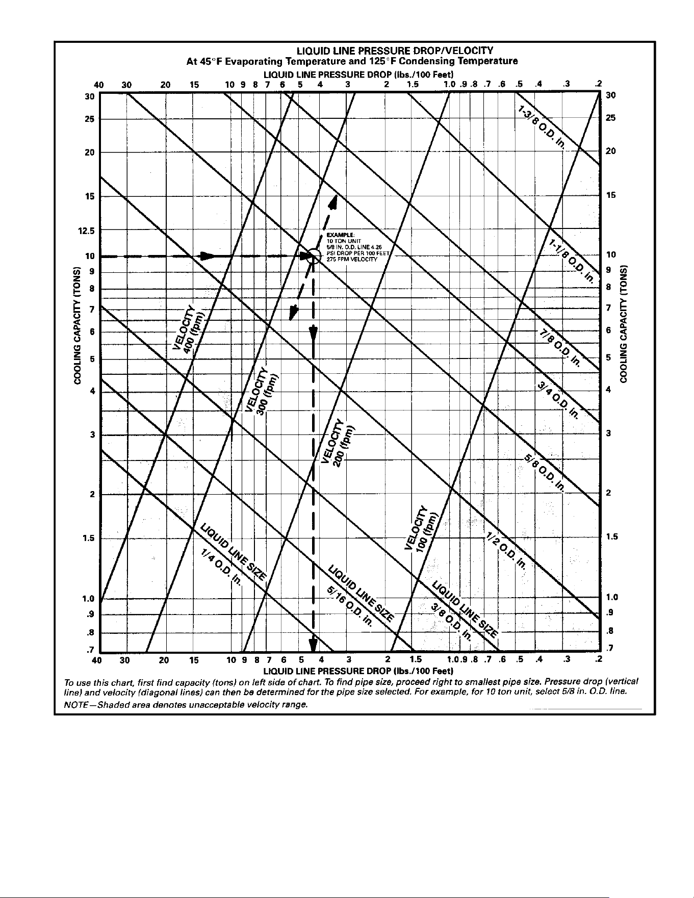
NOTE—Shaded area denotes unacceptable velocity range.
12.5
To use this chart, first find capacity (tons) on left side of chart. To find pipe size, proceed right to smallest pipe size. Pressure drop (vertical line) and
velocity (diagonal lines) can then be determined for the pipe size selected. For example, for 10 ton unit, select 5/8 in. outside diameter. line.
40 30 20 15
40 30 20 15
Figure 5. HFC-410A Liquid Line
Page 13
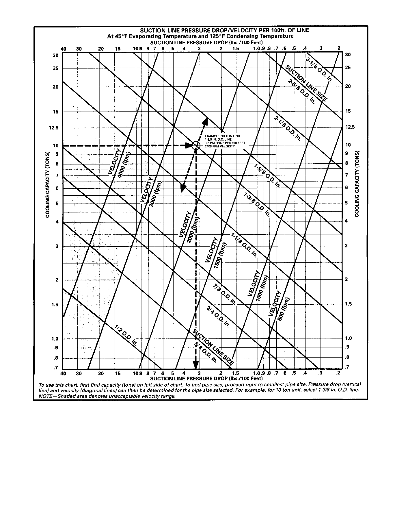
HCFC-22
HCFC-22
HCFC-22
Figure 6. HCFC-22 Suction Line
Page 14
REFRIGERANT HFC-410A SUCTION LINE PRESSURE DROP/VELOCITY PER 100ft. OF LINE
At 45_F Evaporating Temperature and 125_F Condensing Temperature
30
25
20
15
10
9
8
7
6
5
4
3
2
1.5
1.0
.9
.8
.7
10 9 8 7 6 5 4 3 2 1.5 1.0 .9 .8 .7 .6 .5 .4 .3 .2
HFC-410A SUCTION LINE PRESSURE DROP (pounds./100 Feet)
COOLING CAPACITY (TONS)
30
25
20
15
10
9
8
7
6
5
4
3
2
1.5
1.0
.9
.8
.7
COOLING CAPACITY (TONS)
10 9 8 7 6 5 4 3 2 1.5 1.0 .9 .8 .7 .6 .5 .4 .3 .2
HFC-410A SUCTION LINE PRESSURE DROP (pounds./100 Feet)
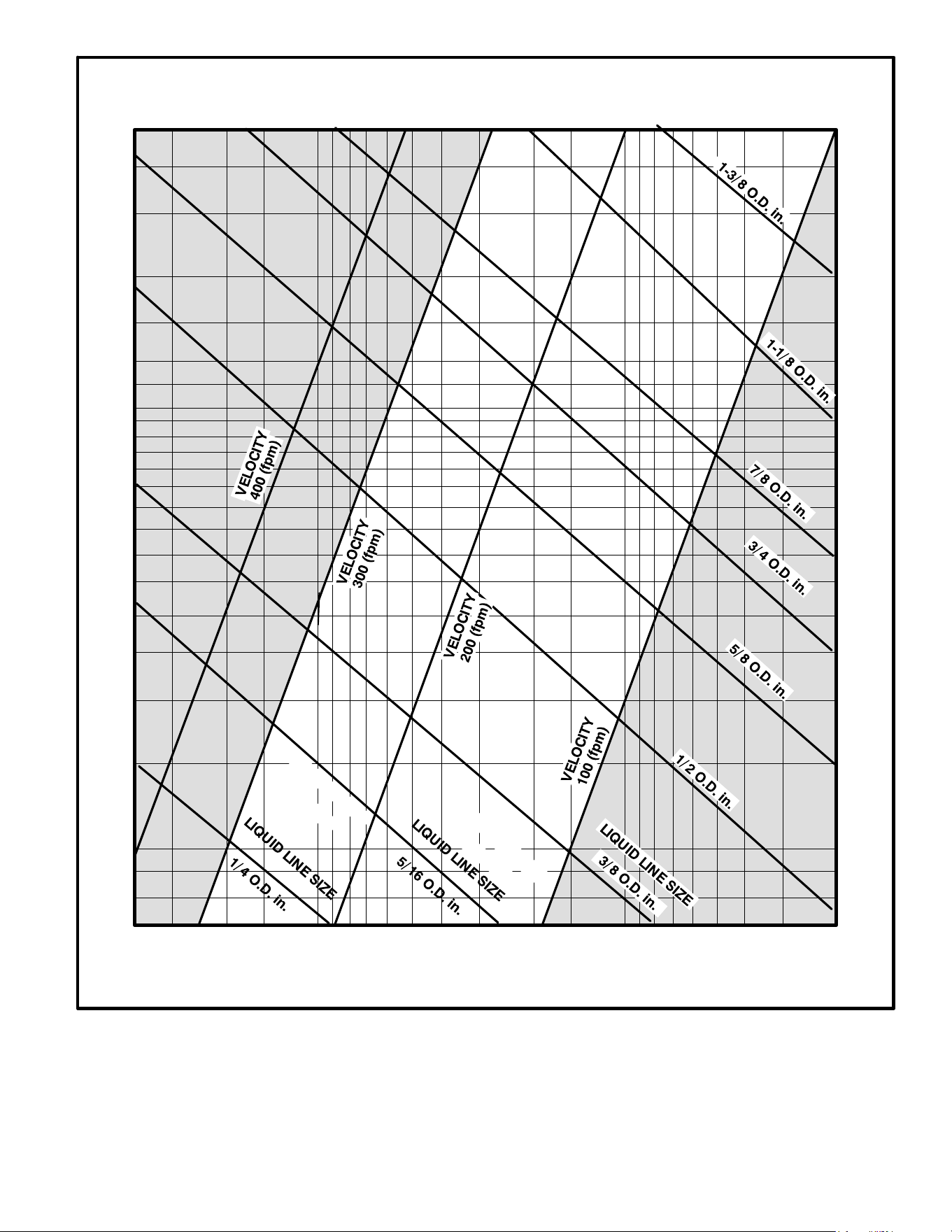
NOTE—Shaded area denotes unacceptable velocity range.
40 30 20 15
40 30 20 15
12.512.5
To use this chart, first find capacity (tons) on left side of chart. To find pipe size, proceed right to smallest pipe size. Pressure drop (vertical line) and
velocity (diagonal lines) can then be determined for the pipe size selected. For example, for 10 ton unit, select 1‐3/8 in. outside diameter. line.
600fpm
1200fpm
1500fpm
2000fpm
3000fpm
Figure 7. HFC-410A Suction Line
Page 15
EXAMPLE 5
Given: HCFC-22, 10-ton (single stage) condensing unit on
ground level with a 10 ton evaporator on the third level
above ground and a total of 96 feet (linear) of piping. Unit is
charged with 10F subcooling at 125F condensing
temperature (280 psi HCFC-22 liquid). See figure 8.
10 TON
CONDENSING
UNIT
10 TON
EVAPORATOR
53 FEET
40 FEET
FILTER/DRIER
3 FEET
Given: 10−Ton Evaporator
Find: Liquid Line Size
Solution: Pressure drop
cannot exceed 35 psi.
Tubing Size: 5/8 inch copper
Two 90º long radius elbows @ 5/8 inch O.D. = 1 foot equivalent feet
each.
Total equivalent length = linear length + equivalent length of fittings.
Total equivalent length = 98 feet.
Total friction losses =
4.25 psi
100 feet
x 98 feet = 4.17 psi.
Total pressure drop = Total friction losses + lift losses + filter/drier.
Filter drop = 1 psi (by manufacturer)
Lift losses = 40 feet x ½ psi per foot = 20 psi.
Total pressure drop – 20 psi + 4.17 psi + 1 psi = 25.17 psi.
Answer: 5/8 inch O. D. copper tubing can be used. Pressure loss
does not exceed maximum allowable pressure drop (6ºF to 7ºF
subcooling will be available at the expansion valve and velocity is
acceptable.
Figure 8. Liquid Line Sizing Example
Find: Select line size from figure 4.
Figure 4 illustrates the relationship between liquid line
sizing, pressure drop per 100 feet, velocity range and
tonnage. When using liquid line solenoid valves, velocities
should not exceed 300 fpm to avoid liquid hammer when
closing. Enter figure 4 from left and extend to the right to the
smallest tube size that will not exceed 300 fpm velocity.
Solution: For a 10 ton system, 5/8 inch outside diameter
line with 4.25 psi per 100 feet drop is selected. Now,
calculate pressure drop due to friction and liquid lift to
determine if this is a good selection.
The pressure lost to two elbows must be added to the
equation. The total friction drop for 96 feet of 5/8 inch
outside diameter. pipe plus (from table 8) 1 equivalent foot
per elbow = 98 equivalent feet.
Figure 4 shows that, in a 10 ton system, we can expect 4.25
psi drop per 100 feet of 5/8 inch outside diameter. copper.
When we multiply 4.25/100 by 98 equivalent feet, we see
that the total friction loss is 4.17 psi.
Now, we must add the pressure drop for vertical lift.
HCFC-22 pressure drop is ½ psi per foot of vertical lift.
When multiplied by 40 feet vertical lift we find that pressure
drop due to lift = 20 psi.
Finally, we have added a filter drier to the liquid line which
has 1 psi drop (this number provided by manufacturer).
Add the three components of pressure drop together to find
that the total pressure drop in this 5/8 inch line = 25.17 psi.
Now, by comparing 25.17 psi to our maximum allowable
pressure drop we find that this setup falls well within the
acceptable range. The 5/8 inch line, therefore, is a good
selection because it is well below the maximum allowable
pressure drop, is in a satisfactory velocity range, uses
minimum refrigerant and provides sufficient pressure at the
expansion valve.
ALTERNATIVE PIPE SIZE
Suppose ¾ inch outside diameter. line with 1.6 psi drop per
100 feet had been selected. The total equivalent length is
computed by adding the linear length (96 feet.) plus the
equivalent length of the fittings (two 90 elbows at 1.25 feet
each). The total equivalent length is 98.5 feet. The total
friction drop would have been 1.6/100 multiplied by 98.5
feet = 1.57 psi. When the pressure drop due to lift (20 psi)
and the filter drier (one psi) are added we find that the total
pressure drop for ¾ inch line = 22.57 psi.
Yet, ¾ inch line is a less desirable choice. Why?
The difference in pressure drop between 5/8 inch line and
3/4 inch line is only 2.35 psi. But, the larger line adds 5.5
pounds. more refrigerant into the system (see table 10 on
page 9). The risk of refrigerant slugging is increased and
the smaller line will be less costly. The smaller line should
be used.
Page 16
10 TON
CONDENSING
UNIT
10 TON
EVAPORATOR
53 FEET
40 FEET
FILTER/DRIER
3 FEET
Given: 10−Ton Evaporator
Find: Liquid Line Size
Solution: Pressure drop cannot exceed 35
psi.
Tubing Size: 3/4 inch copper for 10−ton
system
Two 90º long radius elbows @ 3/4 inch O.D. = 1.25 foot equivalent
feet each.
Total equivalent length = linear length + equivalent length of fittings.
Total equivalent length = 98.5 feet.
Total friction losses =
1.6 psi
100 feet
x 98.5 feet = 1.57 psi.
Total pressure drop = Total friction losses + lift losses + filter/drier.
Filter drop = 1 psi (by manufacturer)
Lift losses = 40 feet x ½ psi per foot = 20 psi.
Total pressure drop – 20 psi + 1 psi + 1.57 psi = 22.57 psi.
Answer: ¾ inch O. D. copper tubing can be used. Pressure loss
does not exceed maximum allowable pressure drop (6ºF to 7ºF
subcooling will be available at the expansion valve and velocity is
acceptable.
10−Ton Condensing unit
With 10ºF subcooling at 125ºF
Length of line = 96 feet.
Figure 9. Liquid Line Sizing Example (Alternative)
SIZING SUCTION AND VAPOR LINES
The purpose of the suction line is the return of refrigerant
vapor and oil from the evaporator to the compressor. The
sizing of vertical risers is extremely important. Movement of
oil droplets up the inner surface of the tubing is dependent
on the mass velocity of the gas at the wall surface.
The larger the pipe the greater the velocity required at the
center of the pipe to maintain a given velocity at the wall
surface.
Suction line design is critical. The design must minimize
pressure loss to achieve maximum unit efficiency and yet
provide adequate oil return to the compressor under all
conditions.
Because oil separates from the refrigerant in the
evaporator, the suction velocity must be adequate to sweep
the oil along. Horizontal suction lines require a minimum of
800 fpm velocity for oil entrainment. Suction risers require
1200 fpm minimum and preferably 1500 fpm regardless of
the length of the riser.
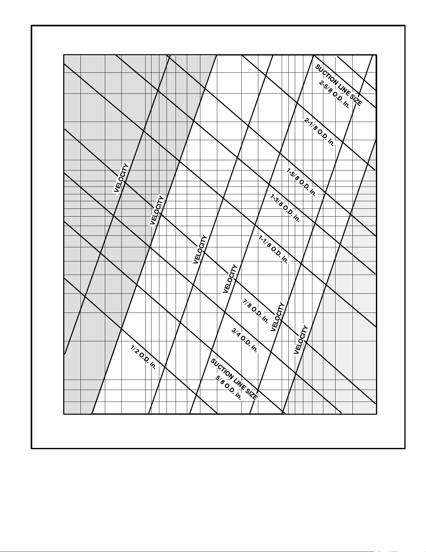
Figure 6 illustrates the relationship between suction line
sizing, pressure drop per 100 feet, velocity and cooling
tonnage. This chart is used to determine suction line
pressure drop which can then be used to determine suction
line capacity loss. This chart can also be used to determine
suction line velocity to assure oil return to the compressor.
Vertical lift does not significantly affect pressure drop.
However, systems will lose approximately 1% capacity for
every pound of pressure drop due to friction in the suction
line. This 1% factor is used to estimate the capacity loss of
refrigerant lines. To use the 1% factor, first you must use
figure 6 to estimate the pressure drop in the total equivalent
length of the lines you choose.
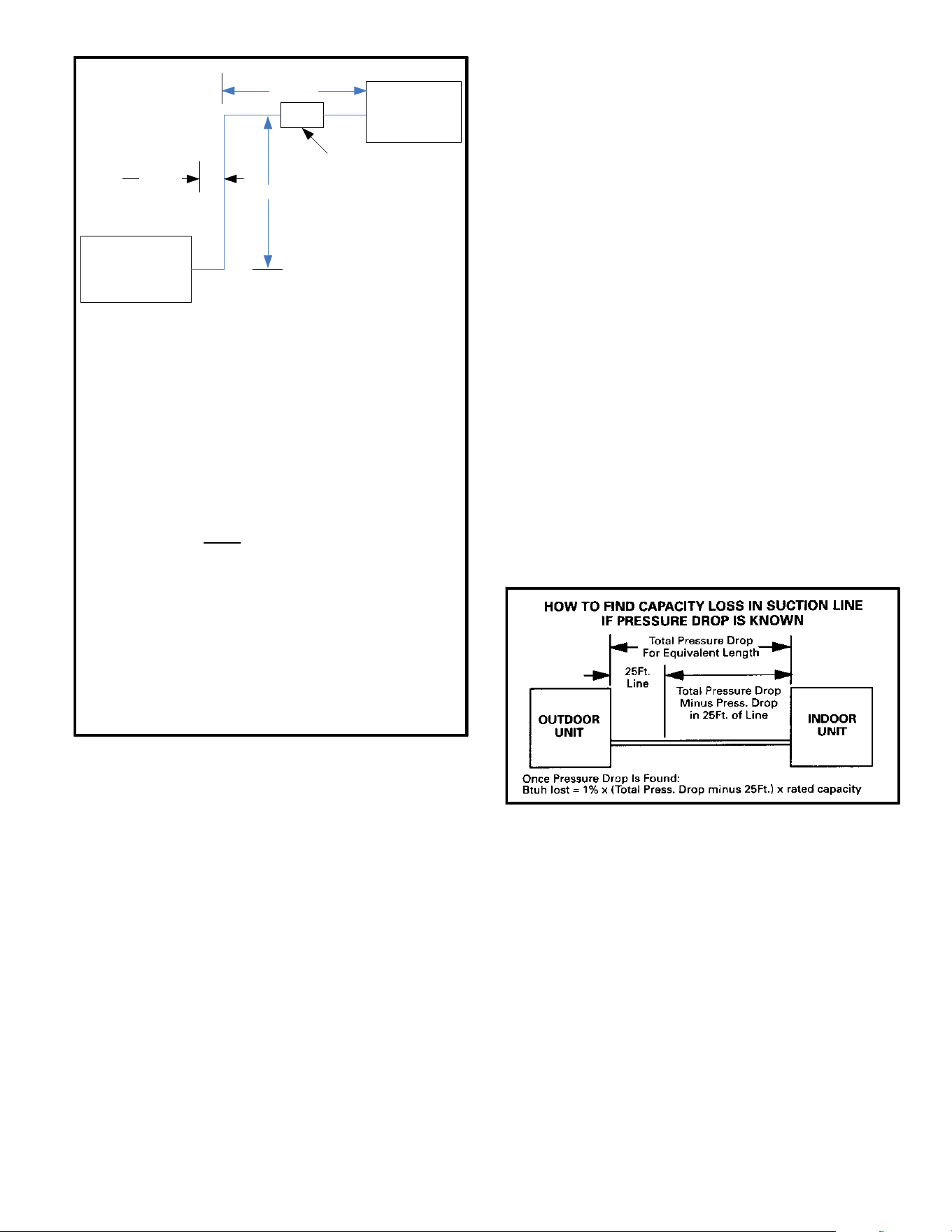
The Engineering Handbook capacity ratings of OEM split
system equipment show the capacity when matched with a
particular indoor coil and 25 feet. of refrigerant line. These
capacity ratings have the loss for a 25 feet. refrigerant line
already deducted. When you use this manual to estimate
the capacity loss due to friction, you must calculate the
pressure drop of the entire refrigerant line then subtract the
pressure drop of a 25 feet. line. See figure 10. Remember,
the objective is to hold refrigerant line capacity loss to a
minimum and maintain velocity for adequate oil return.
Figure 10. How to Find Capacity Loss
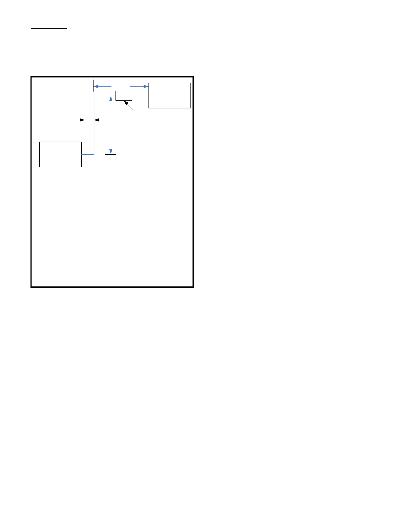
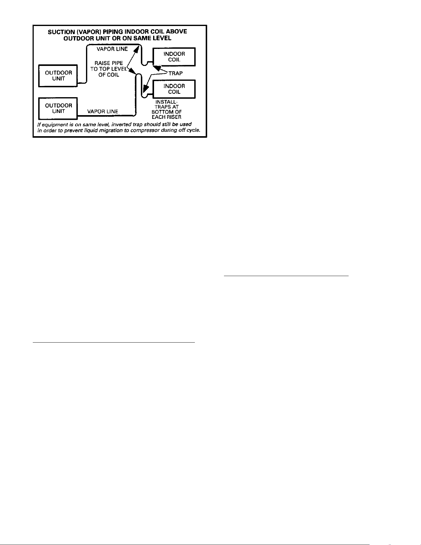
CONSIDERATIONS
When an evaporator is located above or on the same level
as the condensing unit, the suction line must rise to the top
of the evaporator. See figure 11. This helps prevent liquid
from migrating to the compressor during the off cycle. Traps
should also be installed at the bottom of all vertical risers.
In air conditioning systems, horizontal suction lines should
be level or slightly sloped toward the condensing unit. In air
conditioning and heat pump systems, pipe must avoid dips
or low spots that can collect oil. For this reason, hard copper
should be used, especially on long horizontal runs.
Page 17
Figure 11. Suction Line Piping Indoor Coil above
Outdoor Unit or Same Level
To aid in the return of oil, a trap should be installed at the
bottom of any suction riser (remember, a heat pump vapor
line can act as a suction riser when refrigerant flow is
reversed).
When selecting suction/vapor line sizes, the following
points must be remembered:
1. Velocity must be maintained in order to provide
adequate oil return to the compressor.
2. Capacity loss must be held within the job requirements.
Field installed components, such as suction line driers,
mufflers, etc. contribute to both pressure drop and capacity
loss. The resultant pressure drop must be considered (see
manufacturer's data for pressure drop information).
SIZING PROCEDURE
Before selecting pipe size, make a sketch of the layout
complete with fittings, driers, valves etc. Measure the linear
length of each line and determine the number of ells, tees,
valves, driers etc. Add equivalent length of fittings (table 4)
to linear length of pipe to get total equivalent length used in
determining friction loss.
EXAMPLE 1: SUCTION LINE SIZING PROCEDURE
Given: Five ton HCFC-22 (60,000 Btuh) condensing unit
on same level with condenser, with 65 feet of piping and
eight elbows (as in figure 11).
Find: Select tube size from figure 6.
Figure 6 illustrates the relationship between suction line
sizing, pressure drop per 100 feet, velocity range and
tonnage.
Solution: Enter figure 6 from left (tons capacity) and extend
to the right to the smallest tube size with velocity less than
3000 fpm.
Suction line velocity should not exceed 3000 fpm in order to
avoid possible noise complaints. This rule may be slightly
exceeded when added velocity is required to entrain oil
vertically.
1-1/8 inch outside diameter line with 2.8 psi per 100 feet
pressure drop and 1950 fpm velocity is selected. Now
calculate pressure drop due to friction loss to determine if
this is a good selection.
65 feet of pipe, plus eight elbows (1.8 equivalent feet each,
from table 8) = 79.4 feet equivalent length.
When we multiply 2.8/100 by 79.4 equivalent feet, we see
that the total friction loss is 2.22 psi.
1-1/8 inch line appears to meet the requirements in figure 6.
Find the capacity loss in 1-1/8 in. line to determine net
capacity.
Air Conditioning and Heat Pump system capacities are
based on matched systems with 25 equivalent feet of
refrigerant line operating at ARI conditions. As figure 10
shows, the pressure drop in 25 feet of line must be
subtracted from the total equivalent length.
The pressure drop in 25 feet of 1-1/8 inch line is:
2.8/100 multiplied by 25 = 0.7 psi
The additional pressure drop for the line is:
2.22 psi minus 0.7 psi = 1.52 psi
The capacity loss (figure 10) is:
0.01 x 1.52 x 60,000 = 912 Btuh or approximately 1.5%.
EXAMPLE 2: ALTERNATIVE PIPE SIZE
Suppose 7/8 inch outside diameter. line with a pressure
drop of 12 psi per 100 feet had been selected. 65 feet of
pipe, plus eight elbows (1.5 equivalent feet each) = 77 feet
equivalent length. The total friction drop would be 12/100
multiplied by 77 = 9.24 psi.
The pressure drop in 25 feet of 7/8 inch line is:
12/100 multiplied by 25 = 3 psi
The additional pressure drop for the line is:
9.24 psi minus 3 psi = 6.24 psi
The capacity loss (figure 10) is:
0.01 x 6.24 x 60,000 = 3744 Btuh or approximately
6.24%.
This is a poor selection for two reasons:
1. The high velocity may cause excess auction line noise.
2. The capacity loss may not be acceptable if the system
is designed with close tolerance.
Page 18
EXAMPLE 3: SUCTION LINE SIZING PROCEDURE
Given: 7-1/2 ton condensing unit with evaporator lower
than condenser, with 112 feet of piping and four elbows.
The piping includes 20 feet of vertical lift and 92 feet of
horizontal run.
Figure 12. Indoor Coil Below Condenser
Find: Select tube size from figure 6.
Solution: 1-1/8 inch outside diameter. line with 6 psi per
100 feet pressure drop and 2900 fpm velocity is selected.
Now, calculate pressure drop due to friction to determine if
this is a good selection.
From table 8, four ells at 1.8 equivalent feet each = 7.2
equivalent feet. When added to the 112 feet of pipe, the
total equivalent feet becomes 119.2 feet (round up to 120
feet).
When we multiply 6/100 by 120 equivalent feet, we see that
the total friction loss is 7.2 psi.
Use figure 6 to calculate the pressure drop in 25 feet of
1-1/8 inch line. When we multiply 6/100 by 25 feet, we see
that the friction loss is 1.5 psi.
The capacity lost in the total equivalent length of the
refrigerant line (using figures 8 and 10) = 1% x (7.2 – 1.5) x
90,000.
Btuh lost = 0.01 x (5.7) x 90,000
Btuh lost = 5130
Capacity loss for the line selected is approximately 5.7%.
The preceding calculation shows that this is a workable
system but will result in a loss of capacity and efficiency.
EXAMPLE 4: ALTERNATIVE PIPE SIZE
Using the same (7-1/2 ton) example, this time select 1-3/8
inch outside diameter. line. 1-3/8 inch outside diameter. line
with 2 psi per 100 feet pressure drop has 1760 fpm velocity.
Now calculate pressure drop due to friction loss to
determine if this is a better selection.
From figure 5, four elbows at 2.4 equivalent feet each = 9.6
equivalent feet. When added to the 112 feet of pipe, the
total equivalent feet becomes 121.6 feet (round up to 122
feet).
When we multiply 2/100 by 122 equivalent feet, we see that
the total friction loss is 2.4 psi.
Use figure 6 to calculate the pressure drop in 25 feet of
1-3/8 inch line. When we multiply 2/100 by 25 feet, we see
that the friction loss is 0.5 psi.
The capacity lost in the total equivalent length of the
refrigerant line (using figures 8 and 10) = 1% x (2.4 – 0.5) x
90,000.
Btuh lost = 0.01 x (1.9) x 90,000
Btuh lost = 1710
Capacity loss for the line selected is approximately 1.9%.
The conditions in this example will allow either 1-1/8 inch or
1-3/8 inch suction line to be used since capacity loss is
minimized and velocity is sufficient to return oil to the
compressor.
EXAMPLE 5: SUCTION SIZING WITH VARIABLE
CAPACITY — TWO STAGE CONDENSING UNIT
Some variable capacity installations may use a single
suction riser for minimum load conditions without serious
penalty at design load. OEM units with two-stage
compressors have approximately 67% capacity at low
stage and normally do not require double suction risers
Given: 15 ton two-stage condensing unit with a single 15
ton (dual circuit) evaporator.
High Stage Capacity = 15 tons and,
Low Stage Capacity = 9 tons.
The system is plumbed with the evaporator 60 feet below
the condensing unit and 40 feet horizontally away from the
condensing unit. A trap is plumbed at the bottom of the
riser. The trap is composed of 90 ells.
Find: Determine if single suction riser is suitable or if double
suction riser must be used.
TWO STAGE SIZING EXAMPLE
Figure 13. Two Speed Sizing Example
Solution: Select the line size based on full unit capacity (15
tons) 1-5/8 inch outside diameter. line with 3 psi per 100
feet pressure drop and 2600 fpm velocity (at full capacity) is
selected. Then determine the equivalent length of the
segment to calculate the pressure drop.
60 feet of pipe (vertical), plus 40 feet of pipe (horizontal),
plus four 90 elbows (2.8 equivalent feet each) = 111.2
equivalent feet length (round to 111).
From figure 6, 1-5/8 inch outside diameter. suction line with
15 tons capacity has three psi drop per 100 feet. When we
multiply 3/100 by 111 equivalent feet, we see that the total
friction loss is 3.3 psi.
Use table 8 to calculate the pressure drop in 25 feet of 1-5/8
inch line. When we multiply 3/100 by 25 feet, we see that the
friction loss is 0.75 psi.
The capacity lost in the total equivalent length of the
refrigerant line (using figures 8 and 10) = 1% x (3.3 – 0.75) x
180,000.
Page 19
Btuh lost = 0.01 x (2.55) x 180,000
Btuh lost = 4590
Capacity loss for the line selected is approximately 2.55%.
LOW STAGE CAPACITY
1-5/8 inch line appears to be appropriate for this system
operating at full (15 ton) capacity. Now we must check the
low stage (9 ton) capacity to determine if 1-5/8 inch line is
appropriate.
OEM two stage units operate at approximately 60%
capacity when operating on low stage:
15 tons x 0.6 = 9 tons (if an engineering data sheet is
available use the actual capacities rather than this
approximation).
Nine tons capacity when used with 1-5/8 inch pipe (figure 8)
indicates a velocity of 1500 fpm. This is sufficient to return
oil to the compressor and meets the requirement of
maintaining at least 1200 fpm in vertical risers.
When comparing high stage to low stage performance in
this case we find that a single 1-5/8 inch suction riser may
be used and double suction risers are not required.
EXAMPLE 1: SUCTION SIZING VARIABLE CAPACITY
– HOT GAS BYPASS
There are two basic types of hot gas bypass kits. The most
desirable is the type that feeds the hot gas from the
compressor discharge line to a side tap on the distributor in
the evaporator coil. When installed in this manner, full flow
of suction gas is maintained in the suction line and suction
piping should follow standard procedures as outlined in the
previous sections.
The second type of hot gas bypass is installed and
connected within the condensing unit. This is known as a
run-around hot gas bypass in that hot compressor
discharge gas and liquid from the liquid line are circuited to
the hot gas bypass valve and directly into the suction line.
This method reduces flow through the evaporator and
suction line. Special handling of suction risers is required.
Refer to OEM instructions for proper installation of the hot
gas bypass kit.
When to Use Double Suction Risers
If a condensing unit can unload more than 50% either by a
hot gas bypass (run-around cycle) or other mechanical
means, double suction risers may be required.
If the condensing unit unloads less than 50%, suction lines
can be generally sized in accordance with the previous
sections. If the suction velocity is high enough to entrain oil
when the unit is operating at reduced capacity, double
suction risers are generally not required.
In general, double suction risers are required any time the
minimum load on the compressor does not create sufficient
velocity in vertical suction risers to return oil to the
compressor. Double suction risers are also generally
required any time the pressure drop or velocity in a single
suction riser is excessive.
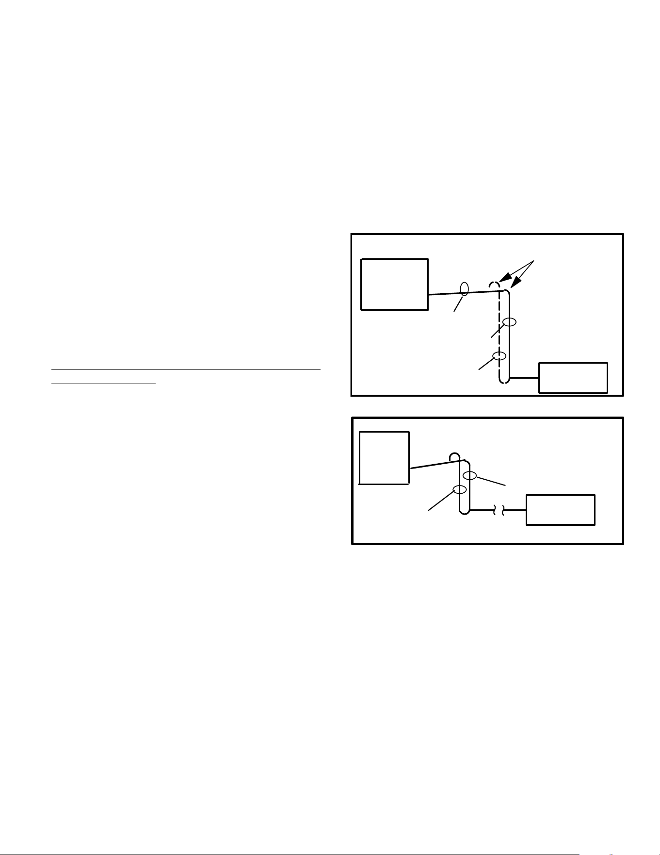
How Double Suction Risers Work
Figure 14 shows a typical double suction riser installation. A
trap is installed between the two risers as shown. During
partial load operation (figure 15) when gas velocity is not
sufficient to return oil through both risers, the trap gradually
fills with oil until the second riser is sealed off. When this
occurs, the vapor travels up the first riser only. With only the
first riser being used, there is enough velocity to carry the
oil. This trap must be close coupled to limit the oil
holding capacity to a minimum. Otherwise, the trap could
accumulate enough oil on a partial load to seriously lower
the compressor crankcase oil level.
The second suction riser must enter the main suction line
from the top to avoid oil draining down the second riser
during a partial load. See figure 15.
EVAPORATOR
CONDENSING
UNIT WITH
HOT GAS
BYPASS
HORIZONTAL SUCTION LINE IS SIZED
TO HANDLE TOTAL LOAD.
IN THE VERTICAL PORTION OF THE LINE,
A SMALLER LINE IS SIZED TO HANDLE
THE REDUCED CAPACITY.
TYPICAL DOUBLE SUCTION RISER
DOUBLE SUCTION
RISER
THE REMAINING LINE IS SIZED TO
HANDLE THE REMAINING CAPACITY
Figure 14. Typical Double Suction Riser
INDOOR
COIL
TYPICAL SIZING
DOUBLE SUCTION RISERS
5 TON
2 STAGE
OUTDOOR
UNIT
3 TON (3/4IN.)
2 TON (5/8IN.)
3/4IN. - SIZING BASED ON MINIMUM LOAD.
5/8IN. - SIZING BASED ON REMAINING LOAD.
Based on Figure 5
Figure 15. Typical Sizing - Double Suction Riser
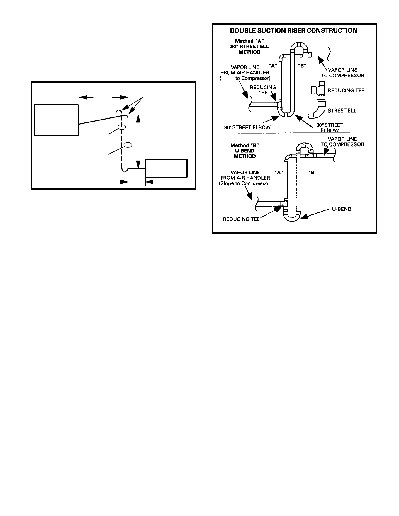
Sample Calculation
Given: Ten ton condensing unit with hot gas bypass
(runaround type) or mechanical unloaders capable of 65%
unloading. Matched evaporator is located below
condensing unit. Piping will require 57 (linear) feet of pipe
(figure 16). Construction without double suction risers will
only require 2 ells.
Find:
1. Select tube sizes for horizontal runs and risers (figure
6).
2. Determine if double suction risers are needed.
3. Size double suction riser for proper system
performance.
Solution: Size each segment based on the tons of
refrigerant that will flow in the segment.
Full load capacity = 10 tons. Minimum load capacity is 35%
of 10 tons = 3.5 tons. The difference between full capacity
and part load capacity is 6.5 tons.
Page 20
From figure 6, select a pipe size for full load capacity. 1-3/8
inch outside diameter. pipe with 3.3 psi drop per 100 feet
and 2400 fpm velocity is selected. Now, by using figure 6,
find the velocity for the selected pipe size at part load
capacity. The part load velocity is approximately 850 fpm.
850 fpm is sufficient to return oil in horizontal runs but not in
vertical risers.
EVAPORATOR
10 TON
CONDENSING
UNIT WITH HOT
GAS
BYPASS
15 FT.
40 FT.
2 FT.
DOUBLE SUCTION RISER EXAMPLE
DOUBLE SUCTION
RISER
A
B
Figure 16. Double Suction Riser
If we tried to size this system by simply reducing the riser
size to 1-1/8 inch, we would find the velocity in the riser to be
excessive (3800 fpm) when the system is operating at full
capacity. As a result of these obstacles, this system will
require construction of double suction risers. Construction
of double suction riser will require five ells and two tees total
for a system.
Size small riser — Riser carrying smallest part of
load
The unit produces 3.5 tons capacity at minimum load.
Select from figure 6 a 7/8 inch outside diameter. line
(smallest line with acceptable velocity). When operating at
3.5 tons capacity, this line will operate at 2500 fpm and will
produce 6 psi drop per 100 feet.
Size larger riser — Riser carrying largest part of load
The larger line carries 6.5 tons capacity at full load. Select
from figure 6 a 1-1/8 inch outside diameter. line (smallest
line with acceptable velocity). When operating at 6.5 tons
capacity, this line will operate at 2500 fpm and will produce
4.5 psi drop per 100 feet.
Putting the Segments Together
Next, we must determine if the line sizes we selected will
result in satisfactory pressure drop between the
condensing unit and the evaporator.
Start by finding the total equivalent feet of the large (B) riser.
15 feet of pipe, plus two tees (branch side of tee at 4.5
equivalent feet each), plus four elbows (1.8 equivalent
feet), plus one tee (line side of tee at 1.0 equivalent feet) =
21.0 equivalent feet length.
Slope
Figure 17. Double Suction Riser Construction
Use the total equivalent length of each riser to compute the
pressure drop of each riser. For the large (B) riser, 1-1/8
inch outside diameter. suction line with 6.5 tons capacity
has 4.5 psi drop per 100 feet. When we multiply 4.5/100 by
31.2 equivalent feet, we see that the total friction loss is 1.4
psi.
For the small (A) riser, 7/8 inch outside diameter. suction
line with 3.5 tons capacity has six psi drop per 100 feet.
When we multiply 6/100 by 21 equivalent feet, we see that
the total friction loss is 1.26 psi.
The total pressure drop for the riser is equal to the average
of the pressure drop in both risers:
1.4 (B riser pressure drop) + 1.26 (A riser pressure drop) =
2.66
2.66 2 = 1.33 (average pressure drop through A and B
risers).
Find the pressure drop for the horizontal run of pipe. 1-3/8
inch pipe at 10 tons of capacity has 3.3 psi drop per 100
feet. When we multiply 3.3/100 by 61 equivalent feet, we
see that the total friction loss is 2.01 psi.
The pressure drop through the risers is added to the
pressure drop through the horizontal run to find the total
pressure drop for the system:
2.01 psi (horizontal run) plus 1.33 psi (avg. riser) = 3.34 psi.
Use figure 6 to calculate the pressure drop in 25 feet of
1-3/8 inch line. When we multiply 3.3/100 by 25 feet, we see
that the friction loss is 0.825 psi.
Page 21
The capacity lost in the total equivalent length of the
refrigerant line (using figures 6 and 10) = 1% x (3.34 –
0.825) x 120,000.
Btuh lost = 0.01 x (2.515) x 120,000
Btuh lost = 3018
Capacity loss for the line selected is approximately 2.5%.
Two Stage Applications
Many two stage applications will require a reduction in
suction riser size to maintain adequate velocity for oil return
at low stage. For example, a 5-ton two stage system will
normally use a 1-1/8 inch suction line (figure 6). A suction
riser in this system may be reduced to 7/8 inch pipe size
while the horizontal runs may use 1-1/8 inch pipe size.
Figure 6 shows the tradeoffs that will result from downsizing
the riser. The disadvantage is that the riser will exceed
3000 fpm when operating at full capacity (potential for
sound transmission). In addition, the pressure drop in the
smaller line will result in significantly greater pressure drop
(capacity loss). The advantage is that the smaller line will
guarantee sufficient velocity for oil return when operating at
reduced capacity.
If, by reducing the riser pipe size, the pressure drop
(capacity loss) becomes unacceptable, the system must be
designed with double suction risers.
Accumulators
Accumulators have to pipe in between the reversing valve
and compressor on heat pumps, which usually do not have
room, especially in the under 5-ton units. Accumulator
sizing should be based on total system charge. A good rule
of thumb is to select an accumulator that can accommodate
2/3 of the total system charge.
Accumulators are not normally required on cooling only
systems with a non bleed TXV and crankcase heater.
Suction line size may be increased to minimize pressure
drop, provided that velocities are adequate. Liquid line
sizes should never be increased or decreased. Larger
liquid lines will add unnecessary charge to the system.
If liquid refrigerant is allowed to flood through an air
conditioning system and return to the compressor before
being evaporated, it may cause damage to the compressor
due to liquid slugging, loss of oil from the crankcase, or
bearing washout. To protect against this condition on
systems vulnerable to liquid damage, a suction
accumulator may be necessary.
Flooding typically can occur on heat pumps at the time the
cycle is switched between heating and cooling, reversal
before and after defrost, and during low ambient heating
operation. Flooding can also occur during normal pressure
equalization at system shut off, especially in systems with
large refrigerant charges. This is true for both heat pumps
and air conditioners.
The accumulator's function is to intercept liquid refrigerant
before it can reach the compressor crankcase. It should be
located in the compressor suction line between the
evaporator and the compressor, and must have provisions
for a positive return of oil to the crankcase so that oil does
not become trapped in the accumulator. The liquid
refrigerant and oil must be metered back to the compressor
at a controlled rate to avoid damage to the compressor.
The actual refrigerant holding capacity needed for a suction
accumulator is governed by the requirements of the
particular application, and should be selected to hold the
maximum liquid refrigerant flood back anticipated.
One of the most critical areas of heat pump application is
the proper control of liquid refrigerant under low ambient
heating conditions. System design must maintain a delicate
balance between sufficient flooding to adequately cool the
compressor, while avoiding excessive flooding which
would adversely affect lubrication. When coil defrost is
required, the compressor is exposed to sudden surges of
liquid that can create extreme stresses in the compressor.
The accumulator can act as a reservoir for refrigerant
during the heating cycle when system imbalance or an
overcharge from field service result in excessive liquid
refrigerant in the system, storing the refrigerant until
needed and feeding it back to the compressor at an
acceptable rate.
Major movements of refrigerant take place at the initiation
and termination of a defrost cycle, and while it is not
necessary or even desirable to stop this movement, it is
essential that the rate at which the liquid refrigerant is fed
back to the compressor be controlled. Again the
accumulator can effectively maintain the crankcase
temperature at acceptable limits.
System Control
To operate at rated capacity and efficiency, all air
conditioning and heat pump systems must be properly
charged. Most equipment manufactured in recent years
depends on subcooling to attain rated capacity and
efficiency. See definition of subcooling in glossary of terms.
A unit can operate at what appears to be normal pressure
and temperature, and if the refrigerant charge does not
provide the proper subcooling for the application, as much
as 8 to 10% of its capacity can be lost without any reduction
in power consumption.
Some OEM equipment is designed to operate at peak
efficiency with less than 10F subcooling. Yet, if the
refrigerant incurs much restriction, such as that
experienced in vertical lift, less subcooling may not be
adequate and a loss of capacity will be experienced.
OEM equipment is designed so the refrigerant charge may
be adjusted in order to obtain 10-12F subcooling on
HCFC-22 units, 6-8F subcooling on HFC-410A units.
Many charging methods are available (charts, superheat,
approach, sight glass) but none of these methods will
assure you of a solid column of liquid at the expansion
valve. A favorite of the service technician has been the sight
glass. It will show that a solid column of liquid is present, but
it will not provide information regarding subcooling. A
common problem with a sight glass in a long line system is
that flash gas can form after the sight glass and before the
expansion valve. The sight glass should not be used to
determine proper system charge.
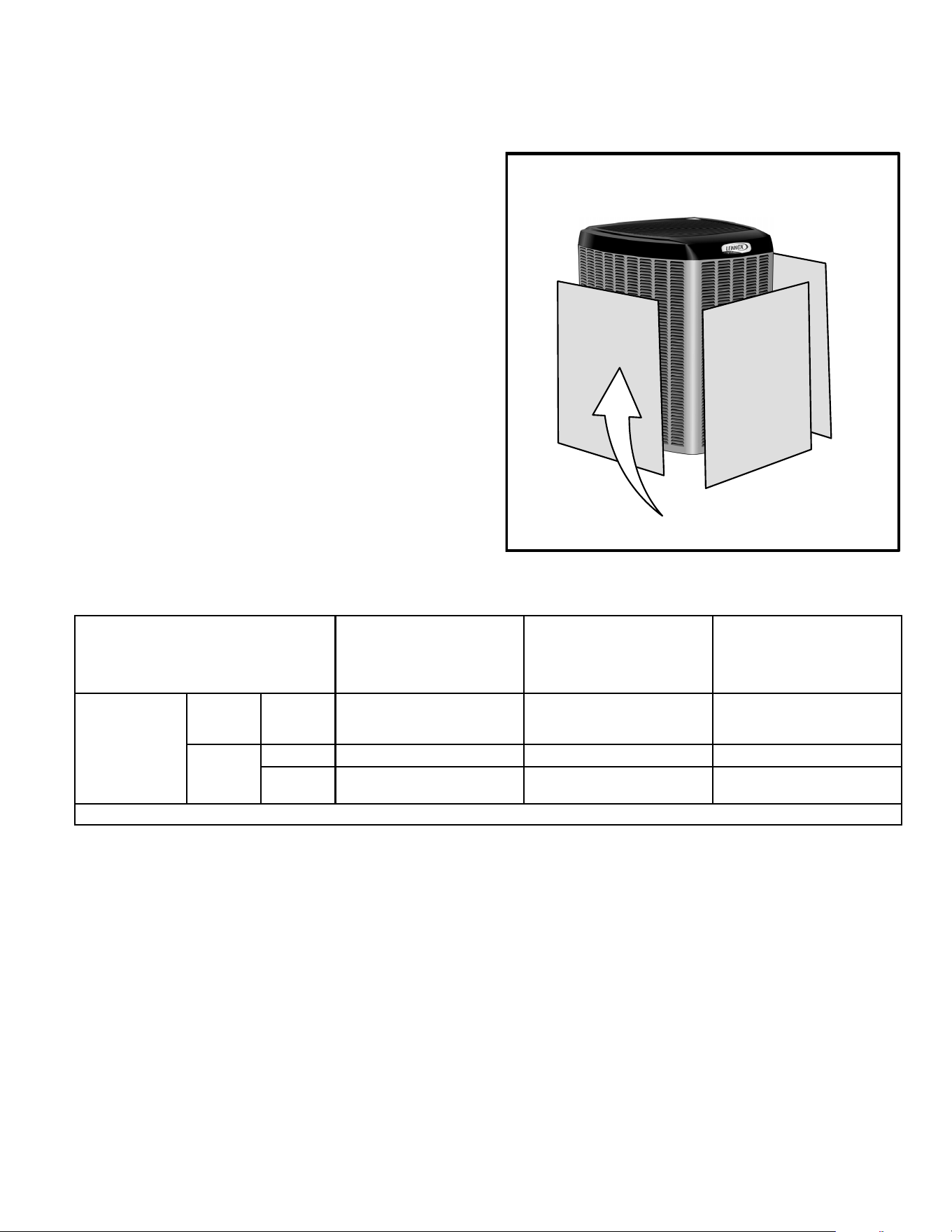
Page 22
HOW TO CHARGE A UNIT USING SUBCOOLING
1. Indoor temperature must be between 70F and 80F.
2. Measure liquid line temperature with temperature
sensor.
3. Hook up gauges to liquid and suction lines.
4. Turn on unit (cooling mode if heat pump – high stage
if two stage compressor) and operate long enough for
pressure to stabilize (at least five minutes).
5. Read condensing temperature from gauge and read
liquid line temperature from the thermometer.
6. To achieve 10F subcooling, liquid line should be 10F
cooler than condensing temperature. The amount of
subcooling will vary with outdoor temperature.
Add refrigerant to make liquid line cooler.
NOTE — If system is grossly overcharged, liquid line will
get warmer as refrigerant is added.
NOTE — After checking charge, if suction pressure is
excessively low, do not add charge. Check filters, air
volume and check for restrictions in system (i.e., strainers,
driers, expansion valve, etc.).
Recover refrigerant to make liquid line warmer.
LOW AMBIENT CHARGING (BELOW 70F OUTDOOR
TEMPERATURE.)
Airflow will need to be restricted in order to boost liquid line
pressure above 240 psig for HCFC-22, or 400 psig for
HFC-410A.
In order to obtain proper results, it is important that you
block equal sections of the coil with cardboard, plastic
sheet or similar material. On formed (wrap around) coils,
the blockage should be applied totally covering the coil from
top to bottom and then extending from side to side.
OUTDOOR COIL SHOULD BE BLOCKED ON SIDE AT A
TIME WITH CARDBOARD OR PLASTIC SHEET UNTIL
PROPER TESTING PRESSURES ARE REACHED.
CARDBOARD OR PLASTIC
SHEET
Figure 18. Blocking Outdoor Coil
Table 11. Low Ambient Cooling Recommendations
Product Family
Low Ambient Operation
Without Low Ambient Kit
Installed
Low Ambient Operation with
Low Ambient Kit added and
field installed Freezestat
Low Ambient Operation with
Low Ambient Kit, field
supplied Outdoor Fan Speed
Control* and Freezestat
Added
Split System
Residential and
Commercial
RFC
Metering
A/C or
Heat
Pump
Down to 60ºF
Kits not available. Operation
below Down to 60ºF is not
recommended.
.....
Expansion
A/C Down to 50ºF Down to 30ºF Down to 0ºF
Heat
Pump
Down to 50ºF Down to 30ºF
Cooling Operation Below 30ºF
is not recommend.
* Requires ball bearing motor construction. Outdoor fan motor may have to be changed in some instances.
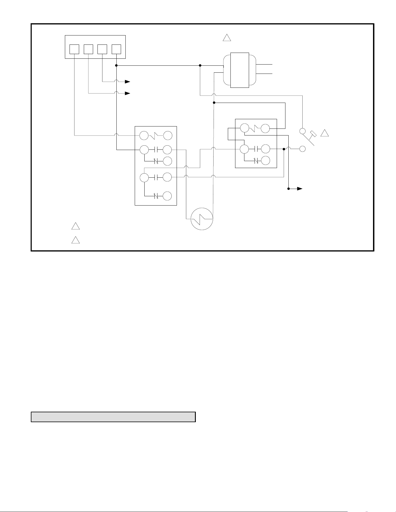
Page 23
YRGW
TO A/H FAN
TO A/H HEAT
THERMOSTAT
CONTROL RELAY
PUMP DOWN RELAY
LIQUID LINE SOLENOID VALVE 24 VAC
C/U Y1 TO
COMPRESSOR
CONTACTOR
LOW PRESSURE
SWITCH
A/H TRANSFORMER
L
N
1
2
1
IF NECESSARY REPLACE A/H TRANSFORMER
WITH ONE OF ADEQUATE VA CAPACITY.
INSTALL LOW PRESSURE CONTROL ON SECTION LINE AT CONDENSING UNIT. TO AVOID OIL MIGRATION INTO THE CONTROL BODY,
MOUNT THE LOW PRESSURE CONTROL ABOVE THE HEIGHT OF THE COMPRESSOR.
2
Figure 19. Non-Recycling Pump Down Control - Field Wiring Diagram
VIBRATION AND NOISE
Regardless of how well a condensing unit is isolated, some
noise and vibration will be transmitted through the
refrigerant piping. But this effect can be minimized with
proper design and support of the piping.
On residential units a coil of tubing in the condensing unit
may provide adequate protection against vibration. On
larger commercial unit, flexible hose is often used.
Noise can be caused by gas flow, fans, compressor, and
mounting. Sometimes a combination of gas flow and piping
will create a resonant frequency which can amplify sound
and vibration. OEM has designed the systems to minimize
this effect.
When piping passes through walls or floors, ensure that
piping does not touch any structural members and is
properly supported by hangers. Otherwise vibration can be
transmitted into the building.
System Operation
Cooling-only applications with reciprocating compressor
The following sequence refers to figure 19:
1. On a call for cooling, the thermostat energizes the Y
circuit which in turn energizes the control relay.
2. The control relay energizes the liquid line solenoid
valve and prepares a circuit to energize the
pump-down relay when the low pressure switch closes.
3. Opening the liquid line solenoid valve causes
refrigerant to flow from the higher pressure condenser
and liquid line into the evaporator and suction line.
Pressure in the suction line quickly rises to the 55 psig
cut-in pressure closing the low pressure switch.
4. The low pressure switch energizes the pump down
relay and the compressor contactor starting the
condenser. The pump down relay seals itself around
the control relay.
5. When cooling is satisfied, the thermostat Y circuit is
de-energized dropping out the control relay and the
liquid line solenoid valve. The compressor continues to
operate pumping refrigerant from the evaporator and
suction line into the condenser and liquid line which is
sealed by the closed liquid line solenoid.
6. When the suction line pressure drops to 25 psig the low
pressure switch opens de-energizing the pump down
relay and the compressor contactor. The compressor
cannot operate until there is another call for cooling.
7. Lower cut-in and cut-out pressures may be required for
low ambient cooling operation.
LOW AMBIENT COOLING
All OEM equipment is designed for low ambient cooling
operation down to 50F. Low ambient cooling operation
below 50F requires the addition of OEM low ambient
control kits and a crankcase heater. Cooling operation
below 30F requires OEM low ambient control kit plus a
variable speed controller on the outdoor fan(s). Table 11
refers to line lengths over 50 feet.
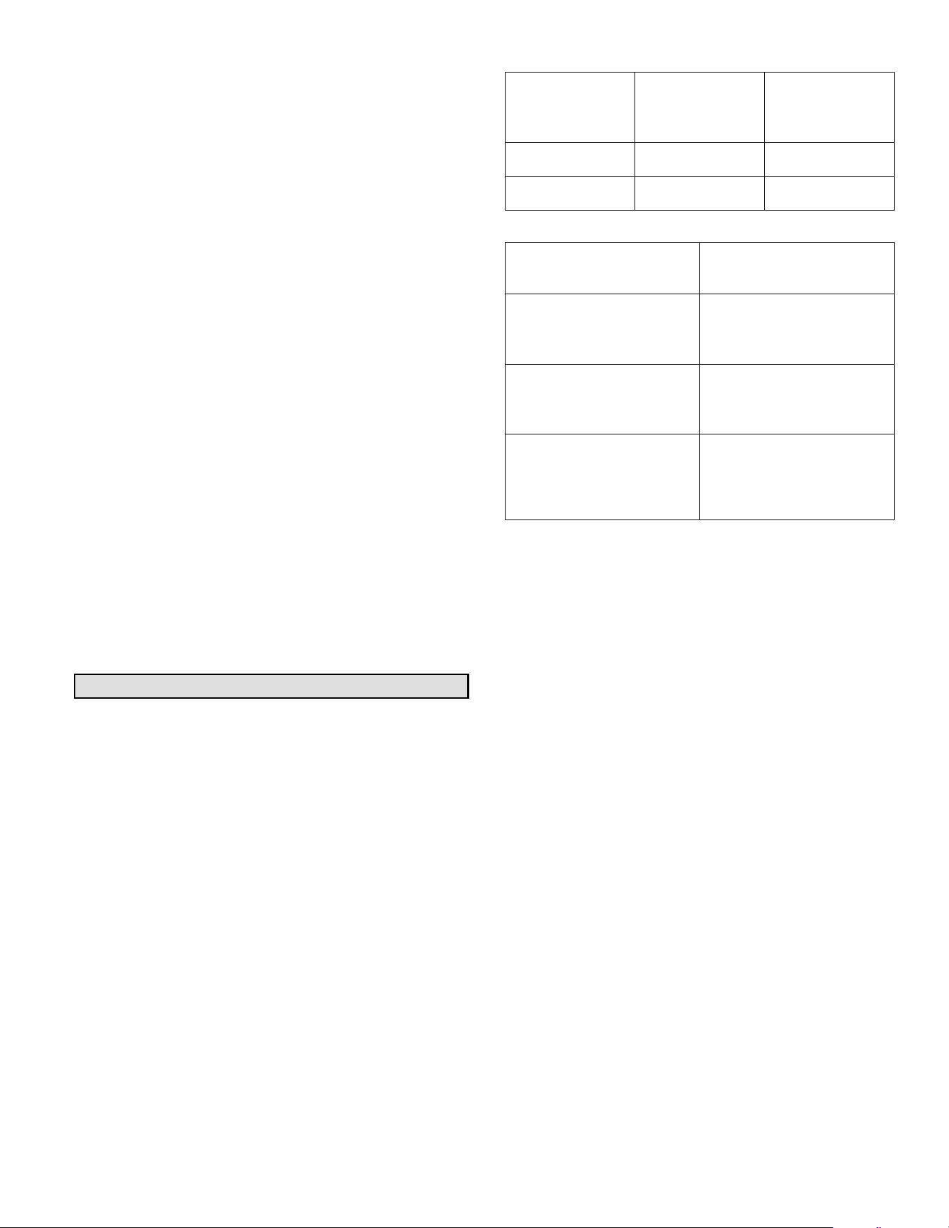
Page 24
OEM low ambient kits are available for all OEM (expansion
valve equipped) units. These kits may need to be installed
and may need to be supplemented with field installed
equipment when applied to systems with long refrigerant
lines. Field installed equipment may include any or all of the
following: solenoid valve installed in the liquid line at the
evaporator, pump-down controls, accumulator, additional
crankcase heaters or capacity unloading.
Factory supplied low ambient kits may include low ambient
thermostat, low pressure switch, relays or any combination
of the above. The variable speed controller, freezestat, and
crankcase heater are available through OEM Dealer
Service Centers.
The operation of each kit can vary somewhat between
cooling and heat pump units. Refer to the low ambient kit for
specific information.
Generally, the low ambient kits are wired to accomplish the
following: Low pressure switches are installed to sense
head pressure and cycle the condenser fan. The fan is
cycled in order to keep head pressure high during low
ambient operation. Variable speed controllers may require
ball bearing fan motors for proper operation at low speed.
If low ambient operation is required and the outdoor unit is
exposed to high prevailing winds, a permanent wind barrier
should be constructed to protect the outdoor coil. In cooling
operation, high prevailing winds can significantly reduce
head pressure. In heat pumps, high prevailing winds can
reduce the effectiveness of the defrost cycle. Use the
minimum installation clearances (provided in Engineering
Handbook) as a guide when constructing a wind barrier.
Wind barriers should extend vertically to the height of the
coil.
Appendix A
HFC-410A REFRIGERANT
The phase out of HCFC-22 refrigerant is currently
underway in the U.S. The official deadline for all equipment
manufacturers to change over to more environmentally
friendly refrigerants is 2010. Aftermarket HCFC-22 will be
available until 2020. HFC-410A is quickly becoming the
refrigerant of choice to replace HCFC-22 in residential and
light commercial air conditioning equipment.
HFC-410A is a near-azeotropic mixture of R-32 and R-125
refrigerants. HFC-410A operates at 50% higher pressure
than HCFC-22. Due to the higher pressure, OEM has
upgraded system components in HFC-410A systems.
HFC-410A must not be used to retrofit existing HCFC-22
equipment. HFC-410A can only be used in equipment
designed for HFC-410A.
Operating pressure points are different for HCFC-22 and
HFC-410A:
Table 12. Head Pressures
50F Evaporator
/ 115F Condens
er
HCFC-22 HFC-410A
Suction Pressure 84 psig 143 psig
Head Pressure 243 psig 390 psig
Table 13. Recommended Hose Pressure Capabilities.
High-pressure Hoses
Minimum 700-psig service
pressure rating
High-pressure manifold
gauge sets
700 psig on the high side
Minimum 180 psig low side
550-psig low-sided retard
High-pressure recovery
units
See manufacturer's
recommendations.
High-pressure recovery
tanks
The recovery cylinder ser
vice pressure rating must
be 400 psig, DOT 4BA400,
or DOT 4BW400.
Proper joint brazing and maintenance becomes even more
critical with HFC-410A. When servicing HFC-410A system,
the contractor must make sure to use components
specifically designed for HFC-410A.
Special service equipment required for working with
HFC-410A includes:
It is recommended that charging with HFC-410A be done in
the liquid phase. Use a commercial-type metering device in
the manifold hose. Charge into the suction line with the
compressor running. See OEM installation instructions for
more details on proper charging procedures.
HFC-410A systems use POE oils. POE oils absorb
moisture very quickly. Keep oil containers tightly closed.
Expose the system to atmosphere as little as possible.
The filter driers uses with HFC-410A systems are designed
with higher working pressures and desiccant materials that
are compatible with POE oils and HFC refrigerants.
Change the filter drier anytime the system is opened to the
atmosphere.
HFC-410A systems manufactured by OEM are either
expansion valve systems or fixed orifice. Proper refrigerant
charge for TXV systems should be checked by the
approach method. Proper refrigerant charge for orifice
systems should be checked by the subcooling method.
The maximum liquid line pressure drop in HFC-410A
systems is 35 PSI, which equates to six degrees of
subcooling. The recommended suction line pressure drop
is five PSI, which equates to two degrees of saturated
suction temperature.

Page 25
PIPING INSTALLATION
Refrigerant lines must not transmit equipment vibration to
any part of the structure. Lines should be supported by
isolation hangers. See figure 20. In no case should
refrigeration lines be left unsupported and free to touch the
structure at any point. Where lines pass through roofs,
walls, floors or sills, or where they come in contact with duct
work, they should be properly isolated. If outside, the
isolation material should be properly waterproofed.
The piping must be supported securely at the proper
places. All piping should be supported with hangers that
can withstand the combined weight of pipe, fittings,
refrigerant and insulation. The hangers must be able to
keep the pipe in proper alignment, thus preventing any
droop.
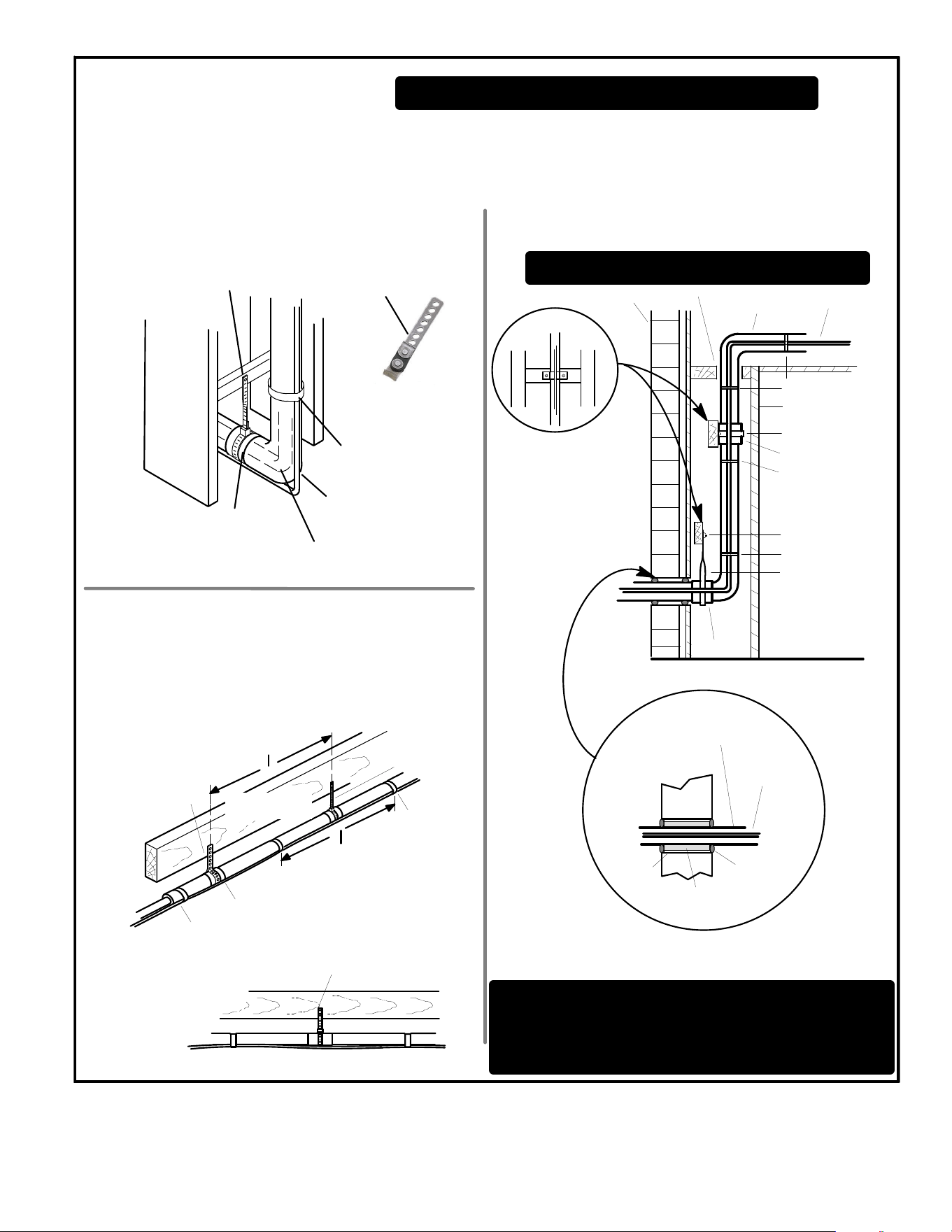
Page 26
ANCHORED HEAVY NYLON
WIRE TIE OR AUTOMOTIVE
MUFFLER‐TYPE HANGER
STRAP LIQUID LINE TO
VAPOR LINE
WALL
STUD
LIQUID LINE
NON-CORROSIVE
METAL SLEEVE
VAPOR LINE - WRAPPED
IN ARMAFLEX
AUTOMOTIVE
MUFFLER‐TYPE HANGER
REFRIGERANT LINE SET — TRANSITION
FROM VERTICAL TO HORIZONTAL
Line Set Isolation — The following illustrations are
examples of proper refrigerant line set isolation:
STRAPPING
MATERIAL (AROUND
VAPOR LINE ONLY)
TAPE OR
WIRE TIE
WIRE TIE (AROUND
VAPOR LINE ONLY)
FLOOR JOIST OR
ROOF RAFTER
TAPE OR
WIRE TIE
To hang line set from joist or rafter, use either metal strapping materi
al or anchored heavy nylon wire ties.
8 FEET (2.43 METERS)
STRAP THE VAPOR LINE TO THE
JOIST OR RAFTER AT 8 FEET (2.43
METERS) INTERVALS THEN STRAP
THE LIQUID LINE TO THE VAPOR LINE.
FLOOR JOIST OR
ROOF RAFTER
REFRIGERANT LINE SET — INSTALLING
HORIZONTAL RUNS
NOTE — Similar installation practices should be used if line set
is to be installed on exterior of outside wall.
PVC
PIPE
FIBERGLASS
INSULATION
CAULK
OUTSIDE
WALL
VAPOR LINE WRAPPED
WITH ARMAFLEX
LIQUID
LINE
OUTSIDE WALL
LIQUID LINE
VAPOR LINE
WOOD BLOCK
BETWEEN STUDS
STRAP
WOOD BLOCK
STRAP
SLEEVE
WIRE TIE
WIRE TIE
WIRE TIE
INSIDE WALL
REFRIGERANT LINE SET — INSTALLING
VERTICAL RUNS (NEW CONSTRUCTION SHOWN)
INSTALLATION
LINE SET
NOTE — Insulate liquid line when it is routed through areas where the
surrounding ambient temperature could become higher than the
temperature of the liquid line or when pressure drop is equal to or
greater than 20 psig.
NON-CORROSIVE
METAL SLEEVE
IMPORTANT — Refrigerant lines must not contact structure.
NON-CORROSIVE
METAL SLEEVE
8 FEET (2.43 METERS)
IMPORTANT — Refrigerant lines must not contact wall
WARNING — Polyol ester (POE) oils used with HFC-410A
refrigerant absorb moisture very quickly. It is very important that the
refrigerant system be kept closed as much as possible. DO NOT
remove line set caps or service valve stub caps until you are ready
to make connections.
Figure 20. Line Set Installation
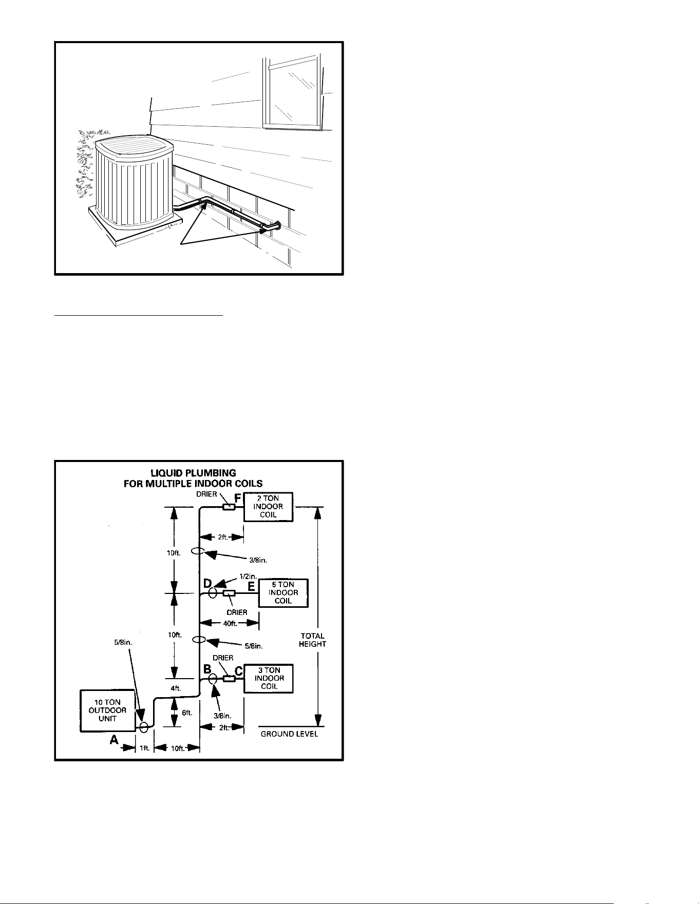
Page 27
TWO 90° ELBOWS INSTALLED IN LINE SET
WILL REDUCE LINE SET VIBRATION.
INSTALL UNIT AWAY FROM
WINDOWS
Figure 21. Outside Unit Placement
COMPLEX LIQUID LINE SIZING
Example 1 – Liquid Sizing with Multiple Evaporators
Occasionally, more than one evaporator may be connected
to one condensing unit. The line sizing method shown here
is for a system with multiple evaporators operating
simultaneously.
In this example, all the evaporators are located above the
condensing unit. All evaporators experience the effects of
liquid lift. The system is equipped with a 2-ton, 5-ton and
3-ton evaporator in order from top to bottom.
Figure 22. Liquid Plumbing
Given: Ten ton commercial (single stage) condensing unit
on ground with three evaporators above condenser. See
figure 22.
Find: Select tube size from figure 8.
Solution: Size each segment based on the tons of
refrigerant that will flow in the segment.
Segment A to B
First solve segment A to B (10 tons). Figure 8 indicates that,
for a 10-ton system, 5/8 inch outside diameter. Liquid line
should be selected (smallest liquid line with acceptable
velocity). Figure 4 also indicates that 5/8 inch line carrying
10 tons of capacity has 4.3 psi drop per 100 feet. Then
determine the equivalent length of the segment to calculate
the pressure drop.
Twenty one feet of pipe, plus three 90 elbows (one
equivalent foot each, from table 4), plus one tee (line side of
tee at 0.8 equivalent feet each, from table 4) = 24.8
equivalent feet length (round up to 25 equivalent feet).
When we multiply 4.3/100 by 25 equivalent feet, we see
that the total friction loss is 1.1 psi.
Now, we must add the pressure drop for vertical lift.
HCFC-22 pressure drop is 1/2 psi per foot of vertical lift.
When multiplied by 10 feet vertical lift we find that pressure
drop due to lift = five psi.
When the two components of pressure drop are added
together we find that the total pressure drop in this 5/8 inch
line = 6.1 psi.
Segment B to C
B to C has a capacity of three tons. Figure 4 indicates a
three ton system should use 3/8 inch outside diameter. line
(smallest line with acceptable velocity). Now, determine the
equivalent length of the segment to calculate the pressure
drop.
Two feet of pipe, plus one tee (branch side of tee at 1.5
equivalent feet each) = 3.5 equivalent feet length (round up
to four equivalent feet).
From figure 4, 3/8 inch outside diameter. liquid line with
three tons capacity has 8.3 psi drop per 100 feet. When we
multiply 8.3/100 by four equivalent feet, we see that the
total friction loss is 0.33 psi.
Vertical lift = 0.
In this segment, the only component of pressure drop is the
equivalent length; 0.33 psi.
Segment B to D
B to D has a capacity of seven tons. Select from figure 4 a
5/8 inch outside diameter. line (smallest line with
acceptable velocity). Then determine the equivalent length
of the segment to calculate the pressure drop.
10 feet of pipe, plus one tee (line side of tee at 0.8
equivalent feet) = 10.8 equivalent feet length (round up to
11 equivalent feet).
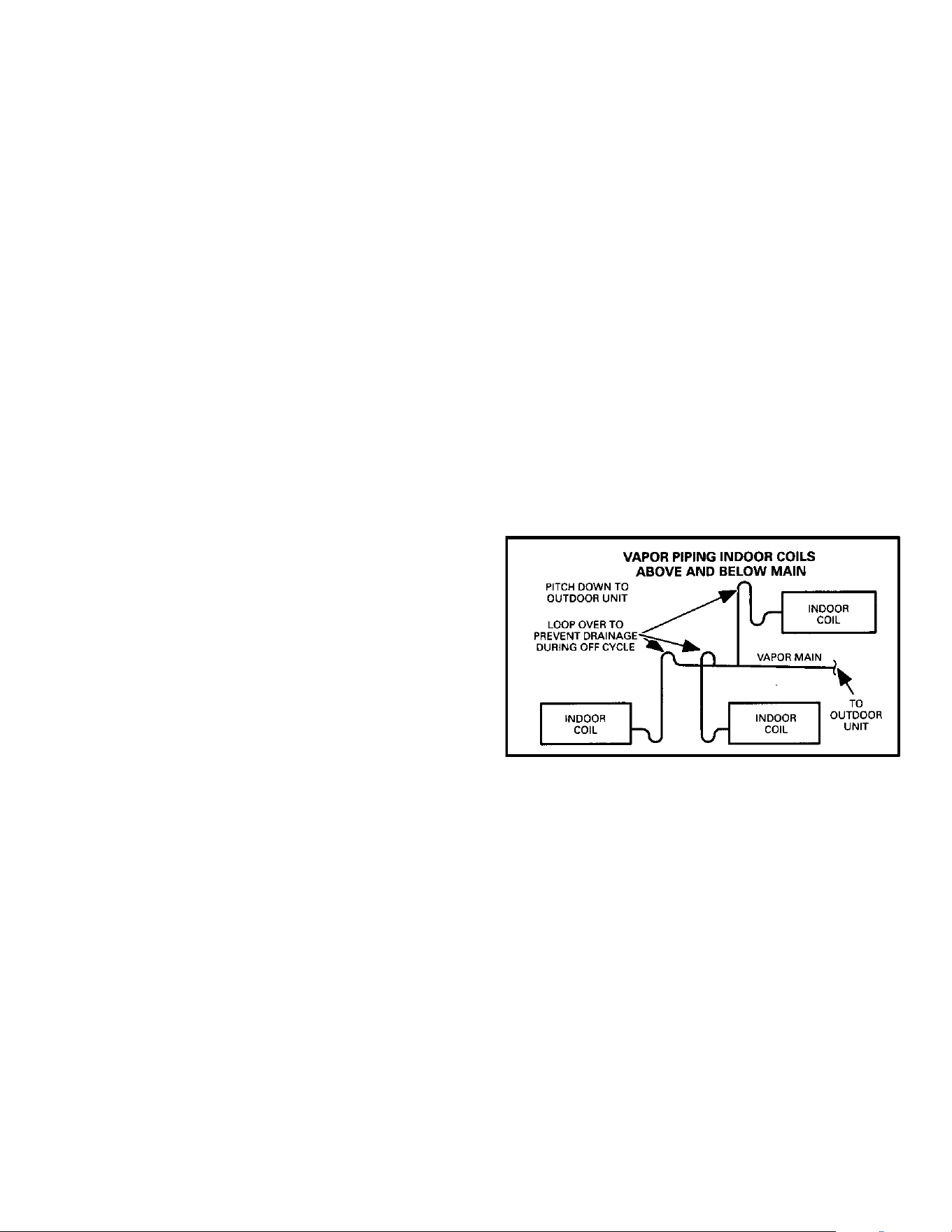
Page 28
From figure 4, 5/8 inch outside diameter. liquid line with 7
tons capacity has 2.3 psi drop per 100 feet. When we
multiply 2.3/100 by 11 equivalent feet, we see that the total
friction loss is 0.25 psi.
Now, we must add the pressure drop for vertical lift.
HCFC-22 pressure drop is 1/2 psi per foot of vertical lift.
When multiplied by 10 feet vertical lift we find that pressure
drop due to lift = five psi.
When the components of pressure drop are added together
we find that the total pressure drop in this 5/8 inch line =
5.25 psi.
Segment D to E
S D to E has a capacity of five tons. Select from figure 4
a ½ inch outside diameter. line (smallest line with
acceptable velocity). Then determine the equivalent
length of the segment to calculate the pressure drop.
S Forty feet of pipe, plus one tee (branch side of tee at 2.0
equivalent feet each) = 42 equivalent feet length.
S From figure 4, 1/2 inch outside diameter. liquid line with
five tons capacity has 4.6 psi drop per 100 feet. When
we multiply 4.6/100 by 42 equivalent feet, we see that
the total friction loss is 1.93 psi.
S Vertical lift = 0.
S In this segment, the only component of pressure drop
is the equivalent length; 1.93 psi.
Segment D to F
S D to F has a capacity of two tons. Select from figure 4
a 3/8 inch outside diameter. line (smallest line with
acceptable velocity). Then determine the equivalent
length of the segment to calculate the pressure drop.
S Twelve feet of pipe, plus one 90 elbow (0.8 equivalent
feet each) = 12.8 equivalent feet length (round up to 13
equivalent feet).
S From figure 4, 3/8 inch outside diameter. liquid line with
2 tons capacity has four psi drop per 100 feet. When we
multiply 4/100 by 13 equivalent feet, we see that the
total friction loss is 0.52 psi.
S Now, we must add the pressure drop for vertical lift.
HCFC-22 pressure drop is ½ psi per foot of vertical lift.
When multiplied by 10 feet vertical lift we find that
pressure drop due to lift = five psi.
S When the components of pressure drop are added
together we find that the total pressure drop in this 3/8
inch line = 5.52 psi.
Putting the Segments Together
Next, we must determine if the line sizes we selected will
result in satisfactory pressure drop between the
condensing unit and each evaporator. To do this we simply
add the total pressure drop of each line segment between
the condensing unit and each evaporator. Remember the
total pressure drop between the condensing unit and
evaporator should be less than 30 psi.
S Total pressure drop A to C = A to B plus B to C.
S Total pressure drop = 6 + 0.33 = 6.33 (Acceptable).
S Total pressure drop A to E = A to B plus B to D plus B
to C.
S Total pressure drop = 6 + 5.25 + 1.93 = 6.33
(Acceptable).
S Total pressure drop A to F = A to B plus B to D plus D
to F.
S Total pressure drop = 6 + 5.25 + 5.52 = 16.77
(Acceptable).
Complex Suction Line Sizing
When a single condenser is connected to more than one
evaporator, there are additional rules which must be
followed when designing the refrigerant piping. These rules
apply to separate coils in separate air handlers as well as to
split coils in a single air handler.
First, the total evaporator load must at least equal the
condensing unit capacity. Next, when evaporators in
different levels are connected to a single main, the suction
line from each coil must rise to the top of that coil before
joining the main. Finally, all connections to a suction main
must loop over and enter the top of the main to avoid the
gravity draining of oil into the suction risers during off
cycles.
Figure 23. Vapor Piping Indoor Coils above and
below Main
Example 2 – Suction Sizing with Multiple Evaporators
On systems with multiple evaporators operating
simultaneously connected to a single condensing unit,
suction lines are sized similar to the method used for sizing
liquid lines. Each line segment is sized based on the tons of
refrigerant flowing in the segment.
In this example, all the evaporators are located above the
condensing unit so that none of the evaporators experience
the effects of suction lift. The system is equipped with a 2
ton, 5 ton and 3 ton evaporator in order from top to bottom.
Given: 10 ton condensing unit with three evaporators,
higher than condenser, operating simultaneously.
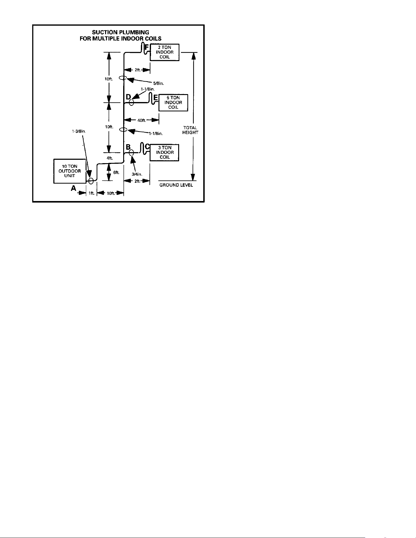
Page 29
Figure 24. Suction Plumbing for Multiple Indoor Coils
Find: Select tube size from figure 6.
Solution: Size each segment based on the tons of
refrigerant that will flow in the segment.
Segment A to B
First solve segment A to B (10 tons). Select from figure 5 a
1-3/8 inch outside diameter. line (smallest suction line with
acceptable velocity). Then determine the equivalent length
of the segment to calculate the pressure drop.
21 feet of pipe, plus three 90 elbows (2.4 equivalent feet
each), plus one tee (line side of tee at 1.8 equivalent feet
each) = 30 equivalent feet length.
From figure 6, 1-3/8 inch outside diameter. suction line with
10 tons capacity has 3.3 psi drop per 100 feet. When we
multiply 3.3/100 by 30 equivalent feet, we see that the total
friction loss is 0.99 psi.
Vertical lift or drop has no effect on pressure in a vapor line.
Segment B to C
B to C has a capacity of three tons. Select from figure 8 a ¾
inch outside diameter. line (smallest line with acceptable
velocity yet with minimum capacity loss). Note figure 8
shows that ¾ inch line has significant pressure drop per 100
feet when combined with 3-ton capacity. If segment B to C
were much longer, the pressure drop would significantly
reduce capacity and a larger (7/8 inch) line would have to
be selected.
Determine the equivalent length of the segment to calculate
the pressure drop.
Two feet of pipe, plus one tee (branch side of tee at 3.5
equivalent feet each), plus six ells (1.25 equivalent feet
each) = 13 equivalent feet length.
From figure 8, ¾ inch outside diameter. suction line with
three tons capacity has 8.5 psi drop per 100 feet. When we
multiply 8.5/100 by 13 equivalent feet, we see that the total
friction loss is 1.11 psi.
Segment B to D
B to D has a capacity of seven tons. Select from figure 8 a
1-1/8 inch outside diameter. line (smallest line with
acceptable velocity). Then determine the equivalent length
of the segment to calculate the pressure drop.
Ten feet of pipe, plus one tee (line side of tee at 1.5
equivalent feet each) = 11.5 equivalent feet length.
From figure 8, 1-1/8 inch outside diameter. suction line with
seven tons capacity has 5.2 psi drop per 100 feet. When we
multiply 5.2/100 by 11.5 equivalent feet, we see that the
total friction loss is 0.6 psi.
Segment D to E
D to E has a capacity of five tons. Select from figure 8 a
1-1/8 inch outside diameter. line (smallest line with
acceptable velocity). Then determine the equivalent length
of the segment to calculate the pressure drop.
Forty feet of pipe, plus one tee (branch side of tee at 4.5
equivalent feet each), plus six elbows (1.8 equivalent feet
each) = 55.3 equivalent feet length.
From figure 8, 1-1/8 inch outside diameter. suction line with
5 tons capacity has 2.8 psi drop per 100 feet. When we
multiply 2.8/100 by 44.5 equivalent feet, we see that the
total friction loss is 1.55 psi.
Segment D to F
D to F has a capacity of two tons. Select from figure 8 a 5/8
inch outside diameter. line (smallest line with acceptable
velocity). Then determine the equivalent length of the
segment to calculate the pressure drop.
12 feet of pipe, plus seven 90 elbow (1.3 equivalent feet
each) = 21.1 equivalent feet length.
From figure 8, 5/8 inch outside diameter. suction line with
two tons capacity has 12 psi drop per 100 feet. When we
multiply 12/100 by 21.1 equivalent feet, we see that the total
friction loss is 2.53 psi. Here also, the pressure drop and
resulting capacity loss are approaching significant levels.
It might be more appropriate to select ¾ inch line in order to
limit the losses. Equivalent length now equals 20.75 feet.
From figure 8, ¾ inch outside diameter. suction line with two
tons capacity has 4.2 psi drop per 100 feet. When we
multiply 4.2/100 by 20.75 equivalent feet, we see that the
total friction loss is only 0.87 psi.
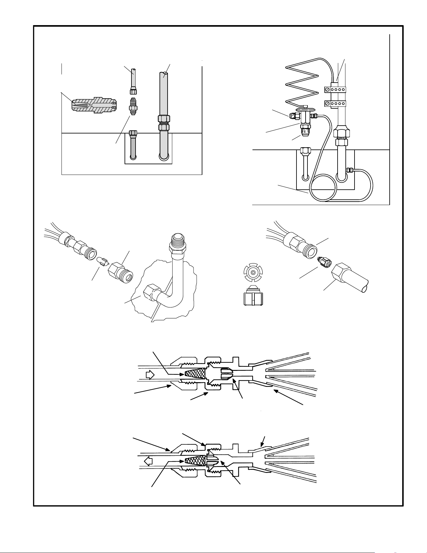
Page 30
LIQUID LINE
SUCTION LINE
RFC II METERING
DEVICE CUTAWAY
RFC II
METERING DEVICE
UP‐FLOW
COIL
ILLUSTRATED
RFCII REFRIGERANT FLOW
CONTROL DEVICE
STRAINER IS PROVIDED TO
PROTECT ORIFICE FROM
FOREIGN MATTER
THERMOSTATIC EXPANSION VALVE
(Air Conditioning System Shown)
CAPILLARY TUBE
SENSING BULB
EXPANSION
VALVE
LIQUID LINE IN
EQUALIZER LINE
VAPOR LINE
FLARE
FITTING
FLARE
FITTING
RFCIII REFRIGERANT FLOW
CONTROL DEVICE
DISTRIBUTOR
“BULLET”
ORIFICE
ORIFICE
BODY
FLARE
NUT
RFCIV REFRIGERANT FLOW
CONTROL DEVICE
DISTRIBUTOR
“BULLET”
ORIFICE
ORIFICE
BODY
SEAL
NUT
SWEAT
CONNECTION
RFCIII REFRIGERANT FLOW CONTROL DEVICE
COOLING MODE
HEATING MODE
ORIFICE FRONT-SEATED
REFRIGERANT FLOWS THROUGH
CENTER OPENING ONLY
ORIFICE BACK-SEATED
REFRIGERANT FLOWS AROUND ORIFICE
AND THROUGH CENTER OPENING
DISTRIBUTOR
CONNECTOR/
STRAINER
LIQUID LINE
CONNECTOR
CONNECTOR/
STRAINER
DISTRIBUTOR
LIQUID LINE
CONNECTOR
LIQUID LINE
LIQUID LINE
STRAINER
STRAINER
Figure 25. Metering Devices
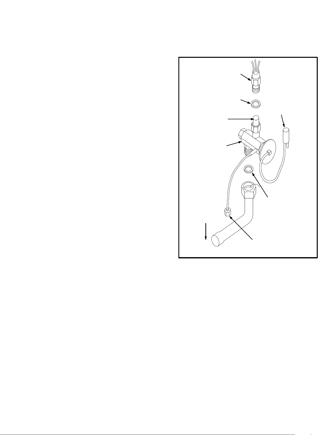
Page 31
Putting the Segments Together
Next, we must determine if the line sizes we selected will
result in satisfactory pressure drop between the
condensing unit and each evaporator. To do this we simply
add the total pressure drop of each line segment between
the condensing unit and each evaporator. Then we convert
the pressure drop into a capacity loss for each coil.
Remember, there is approximately 1% loss in capacity for
each pound of pressure lost to the line.
2-ton evaporator:
S Total pressure drop A to F = A to B plus B to D plus D
to F.
S If 5/8 inch outside diameter. line is used from D to F:
S Total pressure drop = 0.99 + 0.6 + 2.53 = 4.12
S If ¾ inch outside diameter. line is used from D to F:
S Total pressure drop = 0.99 + 0.6 + 0.87 = 2.46
S 1% capacity loss for each pound pressure drop
S 0.01 x 2.46 x 24,000 = 590 Btuh lost if ¾ inch line is
used.
S 0.01x 4.12 x 24,000 = 989 Btuh lost if 5/8 inch line is
used.
3-ton evaporator:
S Total pressure drop A to C = A to B plus B to C.
S Total pressure drop = 0.99 + 1.11 = 2.1 psi
S 1% capacity loss for each pound pressure drop
S 0.01 x 2.1 x 36,000 Btuh = 756 Btuh lost.
5-ton evaporator:
S Total pressure drop A to E = A to B plus B to D plus D
to E.
S Total pressure drop = 0.99 + 0.6 + 1.55 = 3.14 psi
S 1% capacity loss for each pound pressure drop
S 0.01 x 3.14 x 60,000 Btuh = 1884 Btuh lost.
When deciding which line should be used from D to F,
compare the capacity loss to the capacity required. Use the
larger line size only if the additional capacity is needed to
satisfy the job requirements.
If the line segments to these evaporators were significantly
longer resulting in excessive capacity loss, larger suction
lines could be selected as long as satisfactory velocities for
oil entrainment were maintained.
DISTRIBUTOR
ASSEMBLY
EXPANSION
VALVE
(LB−85663A−E Shown)
TEFLON WASHER
(SUPPLIED WITH KIT)
CONNECT
LIQUID LINE
SET HERE
SENSING
BULB
(ATTACH TO
SUCTION LINE)
EQUALIZER CONNECTION
(SECURE TO EQUALIZER
PORT ON SUCTION LINE)
TEFLON WASHER
(SUPPLIED WITH KIT)
STUBBED
END OF VALVE
Figure 26. Typical Residential Applications
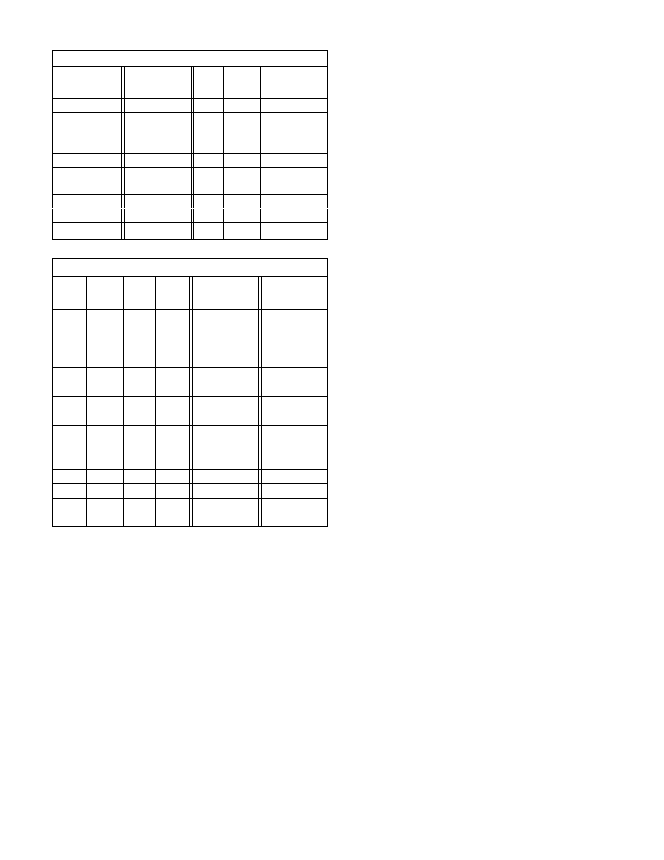
Page 32
Table 14. Operating Temperatures
HCFC22 Temperature (°F) Pressure (Psig)
°F Psig °F Psig °F Psig °F Psig
40 0.6 22 45.5 50 84.7 105 212.9
30 0.9 24 47.9 55 93.3 110 228.6
20 10.2 26 50.3 60 102.4 115 245.2
10 16.6 28 52.7 65 112.2 120 262.5
0 24.1 30 55.2 70 122.5 125 280.7
10 32.9 32 57.8 75 133.4 130 299.7
12 34.9 34 60.5 80 145.0 135 319.6
14 36.9 36 63.3 85 157.2 140 340.3
16 39.0 38 66.1 90 170.0 145 362.0
18 41.1 40 69.0 95 183.6 150 384.6
20 43.3 45 76.6 100 197.0 155 406.3
Table 15. Operating Temperatures
HFC-410A Temperature (°F) - Pressure (Psig)
°F Psig °F Psig °F Psig °F Psig
32 100.8 64 181.6 96 299.4 126 451.8
34 105.0 66 187.7 98 308.2 128 463.5
36 109.2 68 194.1 100 317.2 130 475.6
38 113.6 70 200.6 102 326.4 132 487.8
40 118.0 72 207.2 104 335.7 134 500.2
42 122.6 74 214.0 106 345.3 136 512.9
44 127.3 76 220.9 108 355.0 138 525.8
46 132.2 78 228.0 110 365.0 140 539.0
48 137.1 80 235.3 112 375.1 142 552.3
50 142.2 82 242.7 114 385.4 144 565.9
52 147.4 84 250.3 116 396.0 146 579.8
54 152.8 86 258.0 118 406.7 148 593.8
56 158.2 88 266.0 120 417.7 150 608.1
58 163.9 90 274.1 122 428.8 152 622.7
60 169.6 92 282.3 124 440.2 154 637.5
62 195.5 94 290.8 126 451.8 156 652.4
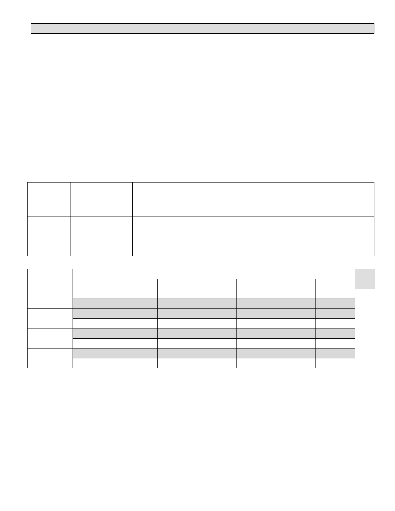
Page 33
Appendix B — XC25 / XP25 Line Set Requirements
The XC/XP25 is a variable capacity cooling and heat pump
system utilizing variable speed compressor technology.
With the variable speed compressor and variable pumping
capacity, additional consideration must be given to
refrigerant piping sizing and application. The guidelines
below are to be used exclusively for the XC/XP25 systems.
COOLING AND HEAT PUMP SYSTEMS (HFC410A)
S Total equivalent length equals 180 feet (piping and all
fittings included).
NOTE — Length is general guide. Lengths may be more or
less, depending on remaining system design factors.
S Maximum linear (actual) length = 150 feet.
S Maximum linear liquid lift = 60 feet.
NOTE — Maximum lifts are dependent on total length,
number of elbows, etc. that contribute to total pressure
drop.
S Maximum length vapor riser equals 60 feet.
S Vertical vapor riser must be sized to the vapor riser
listed in the table 16.
S Up to 50 Linear Feet: use rated line sizes listed in unit
specifications or installation instructions.
S Between 51 150 Linear Feet: Crankcase heater and
nonbleed port TXV factory installed. No additional
components required. Use tables 16 and 17 to
determine the correct liquid and vapor line sizes.
S Over 150 Linear Feet: not recommended.
S Additional oil is not required for systems with line
lengths up to 150 feet except for the XP25-048 and
XP35-060, which will required 2 ounces of oil for every
10 feet beyond 100 feet.
SUCTION TRAPS
For systems with the outdoor unit 5 60 feet above the
indoor unit, one trap must be installed at the bottom of the
suction riser.
Table 16. XC/XP25 Piping Guidelines
Model
Maximum Total
Equivalent Length (ft)
Maximum Linear
(actual) Length (ft)
Maximum Vapor
Riser (ft)
Maximum
Linear Liquid
Lift (ft)
Preferred
Vapor Line
Sizes for
Horizontal
Runs
Required Vapor
Riser Size
024 180 150 60 60 7/8” 5/8”
036 180 150 60 60 7/8” 3/4”
048 180 150 60 60 7/8” 7/8”
060 180 150 60 60 7/8” 7/8”
Table 17. Liquid Line Diameter Selection Table
Unit
Line Size
Total Linear Length (feet)
25 50 75 100 125 150
024
5/16” 25 50 55 48 40 33
Max. Elevation
(ft)
3/8” 25 50 60 60 60 60
036
3/8” 25 50 60 56 51 45
1/2” 25 50 60 60 60 60
048
3/8” 25 50 50 41 31 22
1/2” 25 50 60 60 60 60
060
3/8” 25 50 36 22 8 NR
1/2” 25 50 60 60 60 59
Note Shaded rows indicate rated liquid line size
1. Find your unit on the left side of the table.
2. Start with the rated liquid line size (shaded row) on the outdoor unit
3. Select the actual Total Linear Length of your system shown at the top of the table.
4. The elevation listed in the table is the maximum allowed for the liquid line listed.
5. Select or consider the larger liquid line size shown in the table if the elevation does not meet your requirements.
Page 34
Glossary of Terms
accumulator A tank located in the suction line just ahead of
the compressor. The purpose of the accumulator is to
prevent liquid from entering the compressor.
ambient The temperature of the air surrounding an object.
For a liquid line passing through an attic, the ambient can
approach 180F. OEM cooling and heat pump equipment is
designed to provide adequate cooling when the outdoor
ambient is 115F.
bypass See Hot Gas Bypass.
bypass valve A valve used in hot gas bypass systems. The
valve is plumbed so that when the unit is operating at
reduced capacity, liquid refrigerant and hot gas are
metered into the suction line. See also Hot Gas Bypass.
capillary tube (cap tube) Refrigerant metering device
consisting of one or more small diameter tubes feeding
liquid refrigerant into the evaporator. Cap tubes must never
be used in long refrigerant line applications as they provide
fair to poor refrigerant control in extreme conditions.
capacity (capacity loss) A measure of the quantity of
refrigeration available, measured in Btu per hour or watts.
capacity reduction Air conditioning and heat pump
systems designed to operate at reduced capacity. OEM
two stage equipment is designed to operate at 60% of full
capacity during low stage operation. Some commercial
systems use hot gas bypass as a form of capacity
reduction. A form of capacity reduction is used in almost all
zoning systems.
column of liquid A length of liquid refrigeration line
completely filled with 100% liquid (no bubbles).
condenser A heat transfer device which removes heat
from refrigerant gas, reduces its temperature, removes
latent heat from the refrigerant converting the gas into
liquid, then subcools the liquid.
condensing temperature The temperature in the
condenser coil below which latent heat is removed and gas
is converted into liquid.
distributor A manifold or multi-port fitting located at the
outlet of an expansion valve designed to feed multiple
circuits through the evaporator.
double suction riser A type of suction riser used in
capacity reduction systems to improve oil entrainment
during reduced capacity operation. A double suction riser
consists of a small riser sized for the capacity of the system
when operating at reduced capacity. A second larger riser
is plumbed in parallel with the small riser to handle the
increased flow when the system is operating at full
capacity.
drier See Filter Drier.
drop 1) A measure of the downward vertical distance
(measured in feet) liquid refrigerant must travel in order to
reach the coil. The weight of the liquid refrigerant increases
the liquid line pressure 1/2 pound per foot. 2) See pressure
drop.
elbow Wrought copper 90 or 45 elbows. Only long radius
elbows should be used as fittings in long refrigerant lines
used with OEM equipment.
entrainment The process of moving oil along the inside
surface of a refrigerant vapor line. Oil droplets/film attach to
the inner surface of the pipe. The refrigerant velocity must
be sufficient to sweep the oil along (entrain the oil) so it may
be returned to the compressor.
expansion valve See Thermostatic Expansion Valve.
equivalent length (total equivalent length) Wrought
copper fittings, filter driers and other devices placed in the
refrigerant line add restriction to the line. The restriction
added to the line is expressed in terms of equivalent feat.
The total equivalent length of a ling is equal to the length of
the pipe plus the equivalent length of all the fittings, filter
driers, etc. placed in the line.
evaporator A heat transfer device (coil) which adds heat to
liquid refrigerant, increases its temperature, adds latent
heat to the refrigerant converting the liquid into gas, then
superheats the gas.
filter drier A device placed in the liquid or suction
refrigerant lines to filter contaminants from the system and
protect the expansion valve and compressor from potential
damage.
flash gas in a liquid refrigerant line, liquid which has lost
temperature and pressure to the point that gas bubbles
begin to form significantly reducing the efficiency of the
system. Flash gas can form as a result of friction losses or
running the liquid line through areas with extremely high
ambients or both.
friction loss
See Pressure Drop.
hammer See Liquid Hammer.
hot gas bypass A form of capacity reduction. The system
diverts hot discharge gas and liquid into the suction line
bypassing the evaporator coil. The most desirable form of
hot gas bypass is the type which feeds hot gas into a side
tap on the distributor on the evaporator coil.
indoor coil The name given to the coil in the indoor unit in
heat pump systems.
lift A measure of the upward vertical distance liquid
refrigerant must travel in order to reach the coil measured in
feet. The weight of the liquid refrigerant reduces the liquid
line pressure 1/2 psi per foot. In air conditioning systems, lift
is a factor only if the evaporator is located above the
condenser. In heat pump systems, lift is always a factor due
to the system's ability to reverse refrigerant flow.
line size The outside diameter (O.D.) of copper pipe used
in refrigeration.
liquid hammer An audible sound heard in liquid refrigerant
lines when solenoid valves close. The noise is a result of
liquid refrigerant traveling at high velocity then stopping
abruptly when the valve closes.
low ambient (temperature) The use of the compressor for
cooling when outdoor temperature is below 50F. Field
installed kits are required to protect the compressor and
ensure proper operation in the event low ambient cooling
below 50 F is required.
main In systems with multiple refrigerant lines, the name
given to the line which feeds or collects refrigerant from
multiple smaller refrigerant lines.

Page 35
maximum allowable pressure drop The amount of
pressure drop a liquid line can experience before flash gas
will begin to form. This number can be calculated if the
amount of sub-cooling leaving the condenser is known by
subtracting the liquid temperature from the saturated liquid
temperature then converting the results into a pressure on
the HCFC-22 saturation chart. The difference in pressure
between saturated liquid temperature and the liquid
temperature is equal to the maximum allowable pressure
drop.
If the outdoor unit is charged to operate with 10F
subcooling at 115F saturated liquid temperature, the
maximum allowable pressure drop will be 30 psi.
metering (metering device) Any device which regulates
the flow of liquid refrigerant into an evaporator.
migrate (migration) The tendency of refrigerant gas to
slowly travel to the coldest part of the piping system during
the off-cycle and condense and collect as liquid.
miscibility The ability of two or more substances to mix,
and form a single homogeneous phase.
multiple evaporators A single condenser operating with
several evaporators at the same time.
non-recycling pump-down control See Pump Down
Control.
oil trap A small U bend typically located in the suction line
where it exits the indoor coil. Short radius elbows should be
used on oil traps to keep the oil volume as small as possible.
outdoor coil The name given to the coil in the outdoor unit
in heat pump systems.
pressure drop (pressure loss) The loss of refrigerant
pressure experienced in copper pipe, usually expressed in
terms of pounds (psi) per 100 feet.
pump-down control A field installed kit consisting of a
solenoid valve located in the liquid line before the
expansion valve. At the end of a cooling cycle, the controls
close the valve. The compressor continues to run until all
refrigerant is returned into the condenser where it is stored
as a liquid. The valve remains closed until the next cooling
demand.
RFC (refrigerant flow control device) OEM' trademark
protected name for various types of refrigerant metering
devices with fixed orifice size -
RFC: Liquid line serves as the expansion device. It has a
precisely sized inside diameter and length which matches
the capacity of the condensing unit and evaporator.
RFCII: Fixed orifice for air conditioners located at
evaporator.
RFCIII: Floating bullet type orifice for heat pump coils which
front seats for cooling and back seats for heating
RFCIV: Fixed bullet orifice for air conditioners.
riser The name of any length of refrigerant pipe which
transports refrigerant vertically upward.
run-around hot gas bypass A type of hot gas bypass
system that diverts hot discharge gas and liquid directly into
the suction line inside the condensing unit. Although this
type of system requires no piping external to the unit, it is
less desirable than feeding into a side tap on the distributor
on the evaporator coil.
saturation temperature The temperature at which a gas
begins to turn into liquid.
sight glass A glass window type device placed in a liquid
line and used for visual inspection of the liquid. It can also
be used to determine the point at which all gas bubbles are
removed from the liquid line. A sight glass is not a good
indicator of subcooling and cannot be used to determine
charge.
sil-phos Brazing material composed of silver,
phosphorous, and copper and used for brazing joints of
copper pipe.
slug A column of liquid refrigerant returned to the
compressor in the suction line. A slug which enters the
compressor can cause permanent compressor damage
due to non-compressibility of liquids.
solenoid valve An electromechanical valve located in the
refrigerant lines and used to shut-off refrigerant flow.
split-coil
A single evaporator or condenser coil which is
plumbed so that a single coil can serve two or more
independent refrigeration circuits.
subcooling Cooling of refrigerant liquid below its saturated
temperature while holding it at saturated pressure.
suction riser See Riser.
superheat Heating of refrigerant gas above its saturated
temperature while holding it at saturated pressure.
thermometer well A device located in the liquid line of most
OEM equipment which allows a thermometer to be inserted
into the liquid line. The well is used for accurately
measuring the temperature of the liquid line for charging
purposes.
thermostatic expansion valve (TXV) An extremely
precise type of expansion device which regulates
refrigerant flow into the evaporator based on the amount of
superheat at the TXV bulb location. An expansion valve is
desirable in long line set applications because it can
maintain control of superheat in extremes of operating
conditions.
trap See Oil Trap.
two stage Condensing (or heat pump) outdoor units
equipped with a two stage compressor. Generally, the
compressor operates at 60% capacity on low stage and
100% capacity on high stage.
TXV See Thermostatic Expansion Valve.
unload (unloading) See Capacity Reduction.
Vapor line Term used with heat pumps to describe the
discharge hot gas line in heating mode and the suction line
in cooling mode. In either mode the line carries refrigerant
in a vapor form.
variable capacity See Capacity Reduction.
velocity A measure of the speed at which refrigerant
travels through a pipe, usually expressed in feet per minute.
wrought copper Hammered refrigeration grade copper
used in refrigerant fittings.