507043-04B Page 1 of 9Issue 1832
Save these instructions for future reference
INSTALLATION INSTRUCTIONS
BA13/16 (SINGLE-STAGE) AIR CONDITIONER
(P) 507043-04B
*P507043-04B*
Manufactured By
Blue Summit LLC
8201 C National Turnpike
Louisville, KY 40214
This manual must be left with the homeowner for future reference.
This is a safety alert symbol and should never be ignored. When you see this symbol on labels or in
manuals, be alert to the potential for personal injury or death.
Improper installation, adjustment, alteration, service
or maintenance can cause property damage, personal
injury or loss of life. Installation and service must be
performed by a licensed professional installer (or
equivalent), service agency or the gas supplier.
WARNING
,QVWDOODWLRQRUUHSDLUVPDGHE\XQTXDOL¿HGSHUVRQVFDQ
result in hazards to you and others. Installation MUST
conform with local building codes and with the National
Electric Code NFPA 70/ANSI C1-1993 or current edition
and Canadian Electrical Code Part 1 CSA .
WARNING
Table of Contents
Safety Precautions ......................................................2
Installation ...................................................................2
Electrical Connections .................................................4
Start-Up Procedure......................................................5
System Operation ........................................................6
Homeowner’s Information ...........................................9
These instructions are intended as a general guide and
do not supersede national, state or local codes in any
way.
These instructions must be left with the property owner.
NOTE
These instructions and warranty are to be given to the
owner or prominently displayed near the indoor air
handler unit.
NOTE TO INSTALLING DEALER
Page 2 of 9 507043-04BIssue 1832
These units are designed for use in residential and
commercial type buildings. Units should be installed
with combinations listed in the Air-Conditioning, Heating
DQG 5HIULJHUDWLRQ ,QVWLWXWH $+5, 'LUHFWRU\ RI &HUWL¿HG
Products. Refer to http://www.ahridirectory.org.
Before installation, inspect the unit for shipping damage.
If damage is found, notify the transportation company
LPPHGLDWHO\DQG¿OHDFRQFHDOHGGDPDJHFODLP
Before installing, modifying, or servicing system, main
electrical disconnect switch must be in the OFF position.
There may be more than 1 disconnect switch. Lock out
and tag switch with a suitable warning label. Electrical
shock can cause personal injury or death.
WARNING
Safety Precautions
Follow all safety codes. Wear safety glasses and work
gloves. Use quenching cloth for brazing operations.
+DYH ¿UH H[WLQJXLVKHU DYDLODEOH 5HDG WKHVH LQVWUXFWLRQV
thoroughly and follow all warning or cautions attached to
the unit.
1. Always wear proper personal protection equipment.
2. Always disconnect electrical power before removing
panel or servicing equipment.
3. Keep hands and clothing away from moving parts.
4. Handle refrigerant with caution, refer to proper MSDS
from refrigerant supplier.
5. Use care when lifting, avoid contact with sharp edges.
Installation
Unit Location
NOTE: In some cases noise in the living area has been
traced to gas pulsations from improper installation of
equipment.
1. Locate unit away from windows, patios, decks, etc.
where unit operation sounds may disturb customer.
2. Ensure that vapor and liquid tube diameters are
appropriate to capacity of unit.
3. 5XQUH¿JHUDQWWXEHVDVGLUHFWO\DVSRVVLEOHE\DYRLGLQJ
unecessary turns and bends.
4. Leave some slack between structure and unit to
absorb vibration.
5. When passing refrigerant tubes through the wall, seal
opening with RTV or other silicon-based caulk.
6. Avoid direct tubing contact with water pipes, duct work,
ÀRRUMRLVWVZDOOVWXGVÀRRUVZDOOVDQGDQ\VWUXFWXUH
7. Do not suspend refrigerant tubing from joists and
studs with a rigid wire or strap which comes in direct
contact with tubing.
8. Ensure that tubing insulation is pliable and completely
surrounds suction line.
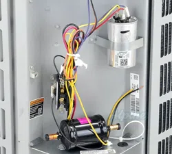
When outdoor unit is connected to factory-approved indoor
unit, outdoor unit contains system refrigerant charge for
operation with indoor unit of the same size when connected
E\IWRI¿HOGVXSSOLHGWXELQJ)RUSURSHUXQLWRSHUDWLRQ
check refrigerant charge using charging information
ORFDWHGRQFRQWUROER[FRYHU
NOTE: Maximum liquid-line size is 3/8 in. O.D. for all
residental applications including long lines.
Outdoor Section
Zoning ordinances may govern the minimum distance the
condensing unit can be installed from the property line.
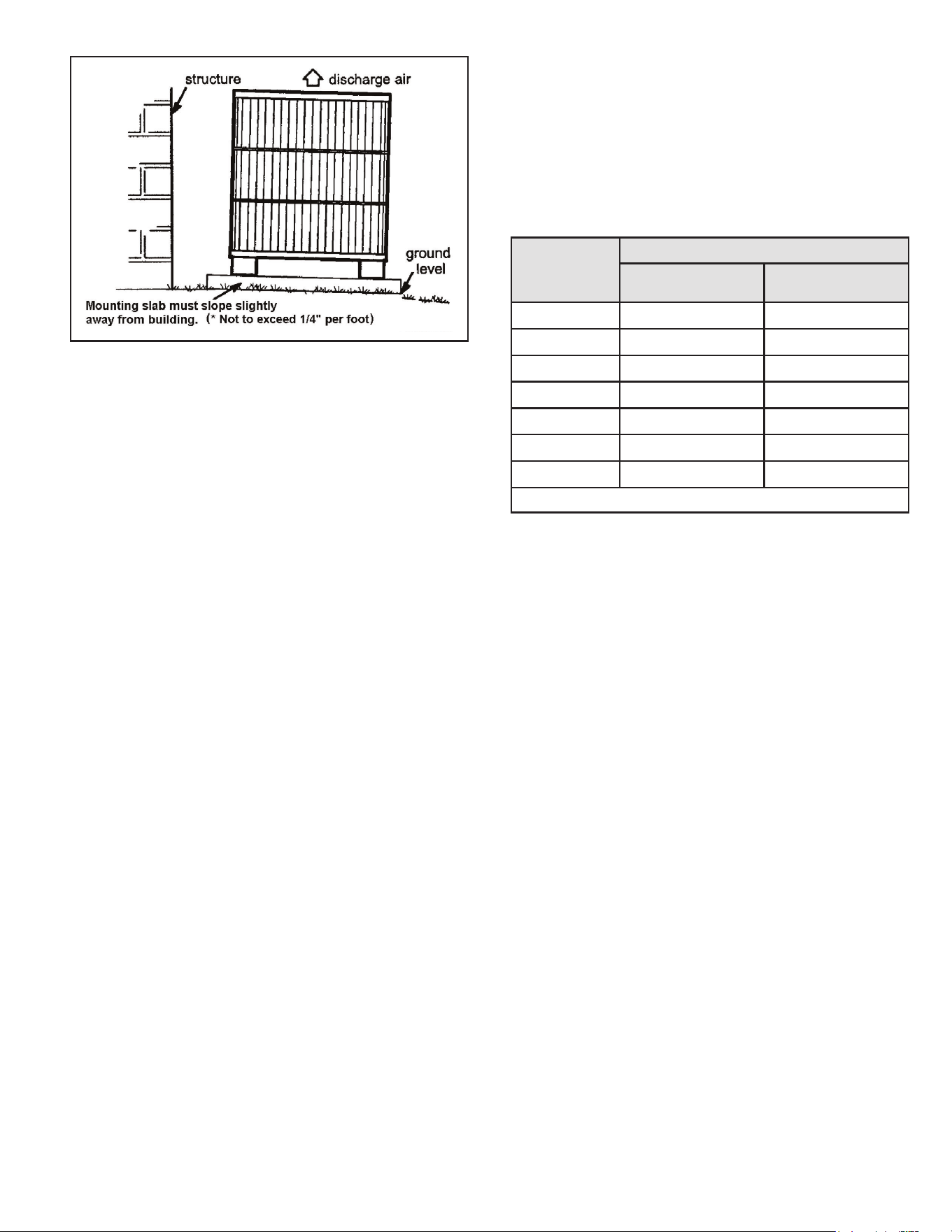
Install on a Solid, Level Mounting Pad
The outdoor section is to be installed on a solid foundation.
7KLV IRXQGDWLRQ VKRXOG H[WHQG D PLQLPXP RI ´ LQFKHV
beyond the sides of the outdoor section. To reduce the
possibility of noise transmission, the foundation slab
should NOT be in contact with or be an integral part of the
building foundation.
If conditions or local codes require the unit be attached to
pad or mounting frame, tie down bolts should be used and
fastened through knockouts provided in unit base pan.
Rooftop Installations
Mount on level platform or frame 6 inches above roof
surface. Place unit above a load-bearing wall and isolate
unit and tubing set from structure. Arrange supporting
members to adequately support unit and minimize
transmission of vibration to building. Ensure roof structure
and anchoring method is adequate for location. Consult
local codes governing rooftop applications.
NOTE: Unit must be level to within ± 1/4 in./ft per
FRPSUHVVRUPDQXIDFWXUHUVSHFL¿FDWLRQV
Clearance Requirements
:KHQLQVWDOOLQJDOORZVXI¿FLHQWVSDFHIRUDLUÀRZFOHDUDQFH
ZLULQJUHIULJHUDQWSLSLQJDQGVHUYLFH)RUSURSHUDLUÀRZ
TXLHWRSHUDWLRQDQGPD[LPXPHI¿FLHQF\3RVLWLRQVRZDWHU
snow, or ice from roof or eaves cannot fall directly on unit.
507043-04B Page 3 of 9Issue 1832
Figure 1. Clearance Requirements
Do Locate the Unit:
• With proper clearances on sides and top of unit (a
PLQLPXPRI´RQWKHWKUHHVLGHVVHUYLFHVLGHVKRXOG
EH´DQG´RQWRS
• On solid, level foundation or pad
• To minimize refrigerant line lengths
Do Not Locate the Unit:
• On brick, concrete blocks or unstable surfaces
• 1HDUFORWKHVGU\HUH[KDXVWYHQWV
• Near sleeping area or near windows
• Under eaves where water, snow or ice can fall directly
on the unit
• With clearance less than 2 ft. from a second uni
• With clearance less than 4 ft. on top of unit
Indoor Coil Piston Selection
The outdoor section must be matched to a factory approved
indoor section. It is mandatory that the installer ensure that
the correct piston or TXV is installed in the indoor section.
,IQHFHVVDU\UHPRYHWKHH[LVWLQJSLVWRQDQGUHSODFHLWZLWK
the correct piston or TXV. See indoor unit instructions
for details of changing the piston or TXV. Contact your
distributor for accessory piston kits.
The correct piston size is shipped with the outdoor unit,
DQGDOVROLVWHGLQWKHVSHFL¿FDWLRQVKHHW'RQRWXVHWKH
piston that comes with the indoor unit, unless it matches
the one listed on the outdoor unit.
Refrigeration Line Sets
Use only refrigeration grade copper tubes. Split systems
may be installed with up to 50 feet of line set (no more than
20 feet vertical) without special consideration. For lines 50
feet or longer, refer to long line set guidelines.
Do not leave the lines open to the atmosphere for any
period of time, moisture, dirt and bugs may contaminate
the lines.
Filter Drier
7KH¿OWHUGULHULVYHU\LPSRUWDQWIRUSURSHUV\VWHPRSHUDWLRQ
and reliability. If the drier is shipped loose, it must be
LQVWDOOHGE\WKHLQVWDOOHULQWKH¿HOG8QLWZDUUDQW\ZLOOEH
void, if the drier is not installed.
Model
13/16 SEER
Liquid Line Suction Line
18 3/8 3/4
24 3/8 3/4
30 3/8 3/4
36 3/8 7/8
42 3/8 7/8
48 3/8 7/8
60 3/8 1-1/8
* Fittings should be supplied by the installer.
Table 1.
Installation of Line Sets
DO NOT fasten liquid or suction lines in direct contact with
WKH ÀRRU RU FHLOLQJ MRLVW 8VH DQ LQVXODWHG RU VXVSHQVLRQ
type of hanger. Keep both lines separate, and always
insulate the suction line. Long liquid line runs (30 feet or
more) in an attic will require insulation. Route refrigeration
line sets to minimize length.
DO NOT let refrigerant lines come in direct contact with
foundation. When running refrigerant lines through the
foundation or wall, openings should allow for a sound
and vibration absorbing material to be placed or installed
between tubing and foundation. Any gap between
IRXQGDWLRQ RU ZDOO DQG UHIULJHUDWLRQ OLQHV VKRXOG EH ¿OOHG
with a vibration damping material.
Page 4 of 9 507043-04BIssue 1832
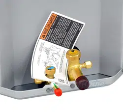
If ANY refrigerant tubing is required to be buried by state
or local codes, provide a 6 inch vertical rise at service
valve.
CAUTION
Before making braze connections, be sure all joints are
clean. Before heat is applied for brazing, dry nitrogen
VKRXOGEHÀRZLQJWKURXJKWKHWXELQJWRSUHYHQWR[LGDWLRQ
and scale formation on the inside of the tubing.
The following is the recommended method for making
braze connections at the refrigerant line connections:
5. Debur and clean refrigerant tube end with emery cloth
or steel brush.
6. ,QVHUWWXELQJLQWRVZDJH¿WWLQJFRQQHFWLRQ
7. Wrap wet rags over valves to protect from heat.
8. $OORZGU\QLWURJHQWRÀRZWKURXJKUHIULJHUDQWOLQHV
9. Braze joint, using a suitable brazing alloy for copper to
copper joints.
10. Quench the joint and tubing with water using a wet
UDJ/HDYHUDJRQ¿WWLQJERG\DQGUHZHWZLWKZDWHUWR
help cool area.
Leak Check
Refrigeration lines and indoor coil must be checked for leaks
after brazing and before evacuation. The recommended
procedure is to apply a trace amount of vapor refrigerant
DSSUR[LPDWHO\WZRRXQFHVRUSVLJLQWRWKHOLQHVHWDQG
indoor coil, then pressurize with 150 psig of dry nitrogen.
Use a refrigerant leak detector to check all joints. The
system may also be checked for leaks using a halide torch
or pressure and soapy solution. After completion of leak
check, relieve all pressure from system before evacuation.
Evacuating and Charging Instructions
It is unlawful to release refrigerants into the atmosphere.
WARNING
These outdoor units are pre-charged at the factory with
adequate refrigerant to handle 15 feet of refrigerant tubing.
1. Connect the vacuum pump to the center hose of the
manifold gauge set, the low-pressure manifold gauge
to the vapor service valve and the high pressure
manifold gauge to the liquid service valve.
2. 7KHYDOYHVVKRXOGEHNHSWLQWKH³IURQWVHDWHG´FORVHG
position. This will allow evacuation of the refrigeration
lines and the indoor coil, without disturbing the factory
charge in the outdoor unit.
3. Follow the vacuum pump manufacturer’s instructions.
Allow the pump to operate until the system has been
evacuated down to 300 microns. Allow the pump to
continue running for an additional 15 minutes. Turn
OFF the pump and leave the connections secured
to the two (2) service valves. After 5 minutes, if the
system fails to hold 1000 microns or less, check all
FRQQHFWLRQV IRU WLJKW ¿W DQG UHSHDW WKH HYDFXDWLRQ
procedure.
4. Isolate the vacuum pump from the system by closing
the shutoff valves on the gauge-set. Disconnect the
vacuum pump.
5. After evacuation of the connecting lines, remove the
VHUYLFHYDOYHFDSDQGIXOO\LQVHUWWKHKH[ZUHQFKLQWRWKH
stem. A back-up wrench is required on the valve body
to open the valve stem. Back-out counterclockwise
until the valve stem just touches the coined edge.
5HSODFHVHUYLFHYDOYHFDSDQGWRUTXHWRIWOERQ´
YDOYHVIWOERQ´YDOYHVIWOERQ´YDOYHV
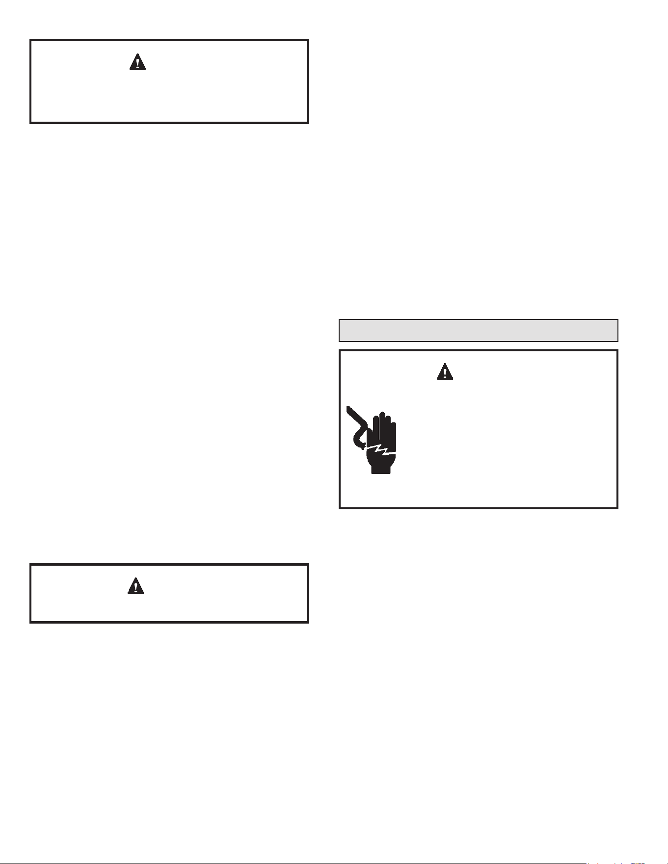
Electrical Connections
ELECTRICAL SHOCK HAZARD!
Turn OFF electric power before connecting
unit, performing any maintenance or
removing panels or doors. More than one
disconnect may be required to turn off all
power.
FAILURE TO DO SO COULD RESULT
IN BODILY INJURY OR DEATH.
WARNING
Be sure to check all local codes to determine that the unit
is installed in accordance with local requirements. Consult
the National Electric Code for wire size requirements. Use
60° C or higher copper wires only. Always provide ground
connections to the outdoor unit. Power supply must agree
with the rating on the unit nameplate.
Provide line voltage power supply to unit from a properly
sized disconnect switch. Route power and ground wires
from disconnect switch to unit. Line voltage connections
DUHPDGHDWWKHOLQHVLGHRIWKHFRQWDFWRULQWKHFRQWUROER[
of the outdoor unit. Follow the wiring diagram attached to
inside of the access panel.
Proper circuit protection recommendations are indicated
on Unit Rating Plate. Time delay fuses are required to
prevent blowing due to starting current (the current in rush
when equipment starts is reffered to as the Locked Rotor
Amps or LRA).
507043-04B Page 5 of 9Issue 1832
Start-Up Procedure
1. Close electrical disconnects to energize system.
2. Set room thermostat at desired temperature. Be sure
set point is below indoor ambient temperature.
3. Set the system switch of the thermostat on COOL and
fan switch for continuous operation (ON) or AUTO, as
desired.
4. $GMXVW UHIULJHUDQW FKDUJH SHU ³$GMXVWLQJ &KDUJH´
section.
Adjusting Charge
Factory charge is shown on the rating label located on the
access panel.
All units are factory charged for 15 feet of connecting line
set. Charge should be adjusted for line set lengths other
than 15 feet. For line sets shorter than 15 feet in length,
remove charge. For line sets longer than 15 feet, add
FKDUJH2LOFKDUJHLVVXI¿FLHQWIRUDOOOLQHOHQJWKVXSWR
feet. For lines longer than 50 feet., refer to long line set
guidelines.
Refrigeration Charge Adjustment
Liquid Line Diameter Oz. Per Linear Foot
´ 0.6
Table 2.
5HPRYHDFFHVVSDQHOWRJDLQDFFHVVWRXQLWZLULQJ([WHQG
wires from disconnect through power wiring hole provided
DQGLQWRXQLWFRQWUROER[)OH[LEOHFRQGXLWLVUHTXLUHGIRUWKH
VZLQJRXWFRQWUROER[IHDWXUH
The unit cabinet must have an uninterrupted or unbroken
ground. The ground must be installed in accordance
with all electrical codes. Failure to follow this warning
FDQUHVXOWLQDQLQMXU\¿UHRUGHDWK
WARNING
&RQQHFWJURXQGZLUHWRJURXQGFRQQHFWLRQLQFRQWUROER[
for safety. Connect power wiring to contactor.
High voltage power connections to 3-phase models is made
WR³3LJ7DLO´OHDGVZLWK¿HOGVXSSOLHGVSOLFHFRQQHFWRUV
Contol Wiring
The control voltage is 24 VAC. NEC Class I insulated 18
AWG is required for control wiring. For lengths longer than
150 feet, contact your local distributor for technical service.
Ensure the room thermostat is properly installed per
instructions shipped with room thermostat. Generally the
WKHUPRVWDW VKRXOG QRW EH H[SRVHG WR VXQOLJKW GUDIWV RU
YLEUDWLRQDQGVKRXOGQRWEHPRXQWHGRQH[WHULRUZDOOV
Low voltage wiring must be separated from high voltage
wiring.
WARNING
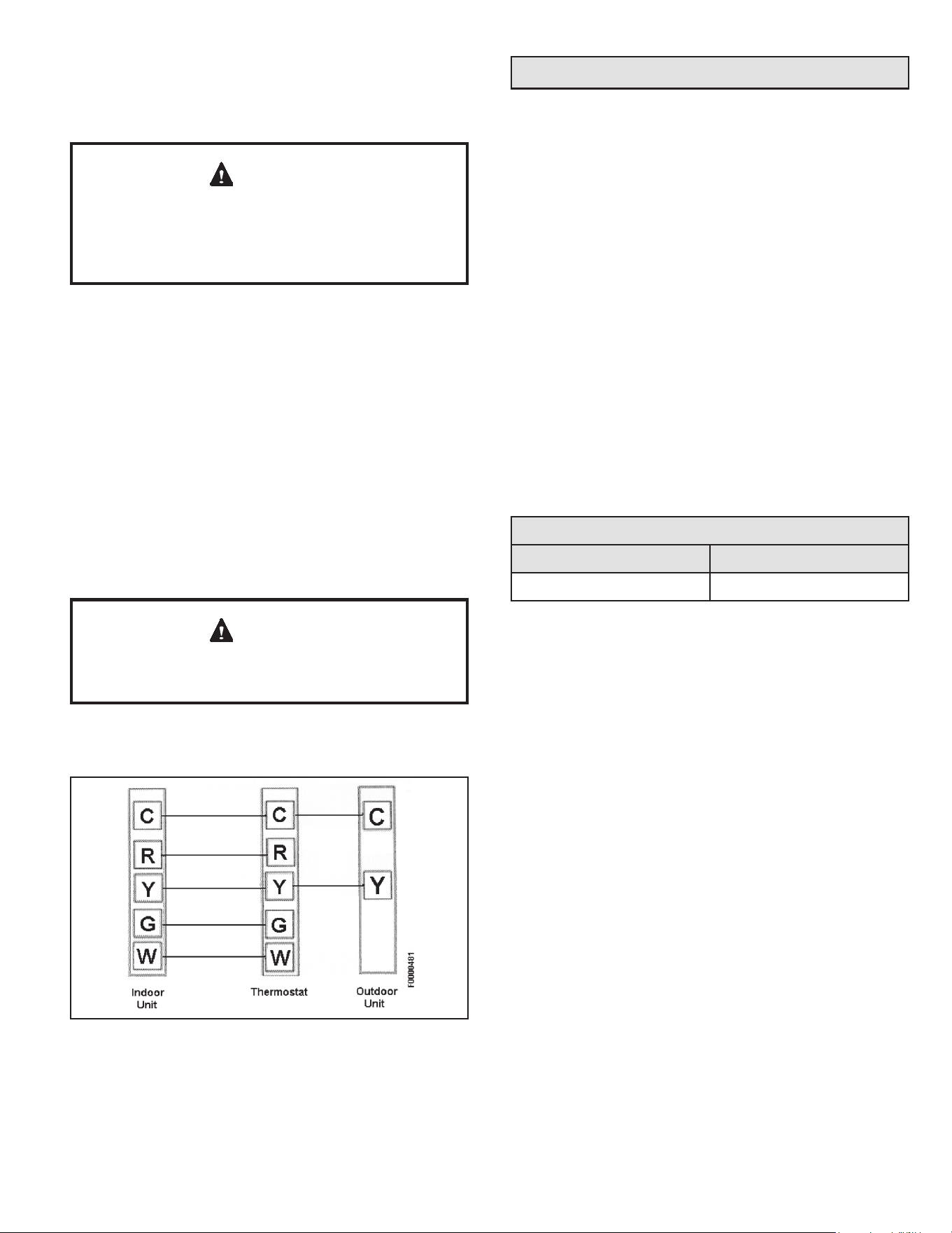
Low voltage connections should be in accordance to the
wiring diagram.
Figure 2. Typical Low Voltage Connection
%ODFNZLUH
<HOORZZLUH

Page 6 of 9 507043-04BIssue 1832
6. Measure indoor air (entering indoor coil) wet-bulb
temperature with a sling psychrometer.
7. Compare superheat reading at service valve with the
FKDUWORFDWHGRQFRQWUROER[FRYHU
8. If unit has a higher suction line temperature than
charted temperature, add refrigerant until charted
temperature is reached,
9. If unit has a lower suction line temperature than
charted temperature, reclaim refrigerant until charted
temperature is reached.
10. Remove charge if superheat is low and add charge if
superheat is high.
Units with Indoor TXV
Units installed with cooling mode TXV require charging
with the subcooling method.
1. Operate unit a minimum of 10 minutes before checking
charge.
2. Measure liquid service valve pressure by attaching an
accurate gage to service port. Determine saturation
temp. from T/P chart.
3. Measure liquid line temperature by attaching an
accurate thermistor type or electronic thermometer to
liquid line near outdoor coil.
4. Calculate subcooling (saturation temp. - measured
WHPS DQG FRPSDUH WR WDEOH RQ EDFN RI FRQWURO ER[
cover.
5. Add refrigerant if subcooling is lower than range shown
in table. Recover refrigerant to decrease subcooling.
6. If ambient temp. is lower than 65° F, weigh refrigerant
according to the name plate data.
NOTE: If a TXV is installed on indoor unit, a hard start kit will
be required on all models with reciprocating compressors.
5HIHUWRWKHVSHFL¿FDWLRQVKHHWIRUGHWDLOV+DUGVWDUWNLWV
are also recommended for areas with utility power lower
than 208 Vac.
System Operation
The outdoor unit and indoor blower cycle on demand
from the room thermostat. When the thermostat blower
switch is in the ON position, the indoor blower operates
continuously.
%HIRUH¿QDODGMXVWPHQWLVPDGHWRWKHUHIULJHUDQWFKDUJH
FKHFNIRUSURSHU LQGRRU DLUÀRZ5HFRPPHQGHGDLUÀRZ LV
350-450 CFM per ton (12,000 Btuh) through a wet coil.
Refer to indoor unit instructions for methods of determining
DLUÀRZDQGEORZHUSHUIRUPDQFH
Cooling Cycle Charge Adjustment Procedure
Units with Indoor Pistons
Units installed with indoor pistons require charging with the
superheat method.
7KH IROORZLQJ SURFHGXUH LV YDOLG ZKHQ LQGRRU DLUÀRZ LV
within ± 20 % of its rated CFM.
1. Operate unit a minimum of 10 minutes before checking
charge.
2.
3.
Measure suction pressure by attaching a gage to
suction valve service port. Determine saturation temp
from T/P chart.
Measure suction temperature by attaching an accurate
thermistor type or electronic thermometer to suction
line at service valve.
4. Calculate superheat (measured temp. - saturation
temp.).
5. Measure outdoor air dry-bulb temperature with
thermometer.
507043-04B Page 7 of 9Issue 1832
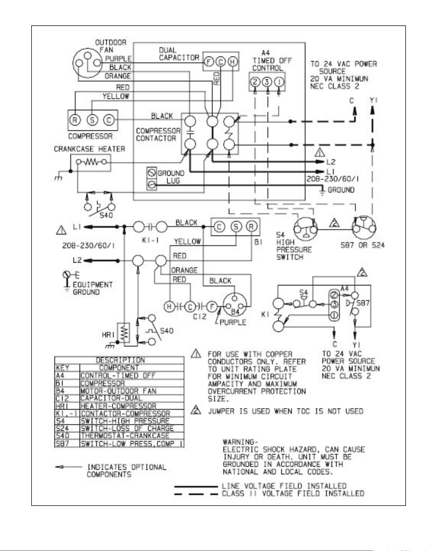
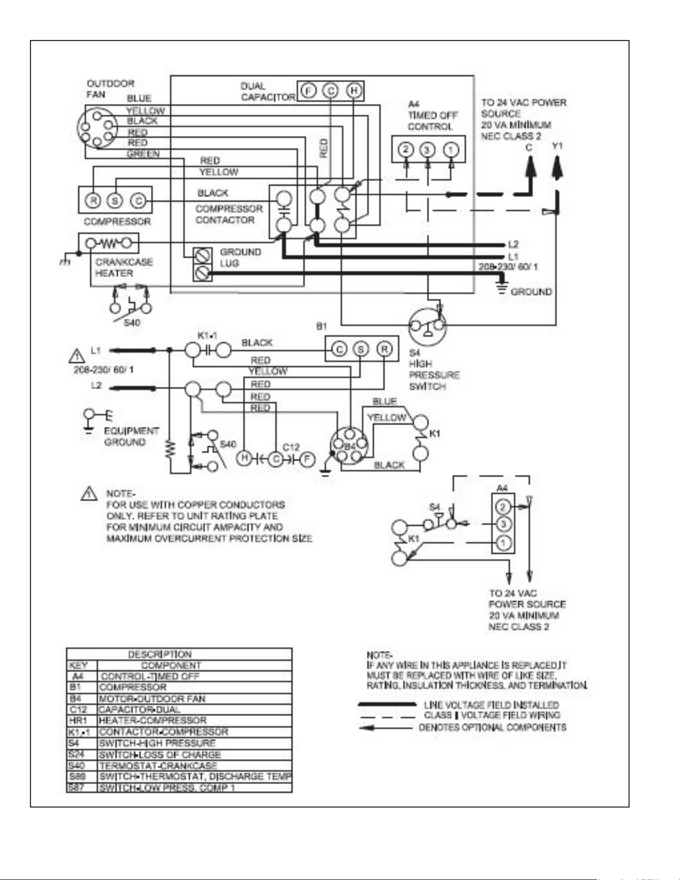
Figure 3. A/C Single Phase Wiring Diagram (single-speed condenser fan)
Page 8 of 9 507043-04BIssue 1832
Figure 4. A/C Single Phase Wiring Diagram (multi-speed condenser fan)
507043-04B Page 9 of 9Issue 1832
Homeowner’s Information
Important System Information
• Your system should never be operated without a clean
DLU¿OWHUSURSHUO\LQVWDOOHG
• Return air and supply air registers should be free from
UHVWULFWLRQVRUREVWUXFWLRQVWRDOORZIXOOÀRZRIDLU
Regular Maintenance Requirements
<RXUV\VWHPVKRXOGEHUHJXODUO\LQVSHFWHGE\DTXDOL¿HG
service technician. These regular visits may include
(among other things) checks for:
• Motor operation
• Ductwork air leaks
• Coil & drain pan cleanliness (indoor and outdoor)
• Electrical component operation & wiring check
• Proper refrigerant level & refrigerant leaks
• 3URSHUDLUÀRZ
• Drainage of condensate
• $LU¿OWHUVVSHUIRUPDQFH
• Blower wheel alignment, balance & cleaning
• Primary & secondary drain line cleanliness
• Proper defrost operation (heat pumps)
There is some routine maintenance procedures you can do
to help keep your system operating at peak performance
between visits.
Air Filter
,QVSHFWDLU¿OWHUVDWOHDVWPRQWKO\DQGUHSODFHRUFOHDQDV
UHTXLUHG'LVSRVDEOH¿OWHUVVKRXOGEHUHSODFHG:DVKDEOH
¿OWHUV PD\ EH FOHDQHG E\ VRDNLQJ LQ PLOG GHWHUJHQW DQG
ULQVLQJ ZLWK FROG ZDWHU 5HSODFH ¿OWHUV ZLWK WKH DUURZV
SRLQWLQJLQWKHGLUHFWLRQRIDLUÀRZ'LUW\¿OWHUVDUHWKHPRVW
common cause of poor heating/cooling performance and
compressor failures.
Indoor Coil
,IWKHV\VWHPKDVEHHQRSHUDWHGZLWKDFOHDQ¿OWHULQSODFH
it should require minimal cleaning. Use a vacuum cleaner
and soft brush attachment to remove any accumulation of
GXVWIURPWKHWRSDQGXQGHUVLGHRIWKH¿QQHGFRLOVXUIDFH
However, perform this maintenance only when the coil is
completely dry.
If the coil cannot be cleaned by this method, call your
dealer for service. It may need a detergent solution and
rinsing with water for cleaning, which may require coil
removal, You should not attempt this yourself.
Condensate Drain
'XULQJFRROLQJVHDVRQFKHFNDWOHDVWPRQWKO\IRUIUHHÀRZ
of drainage and clean if necessary.
Condenser Coils
Grass cuttings, leaves, dirt, dust, lint from clothes dryers,
and fall off trees can be drawn into coils by movement of
WKHDLU&ORJJHGFRQGHQVHUFRLOVZLOOORZHUWKHHI¿FLHQF\RI
your unit and cause damage to the condenser.
Periodically, debris should be brushed from the condenser
coils.
SHARP OBJECT HAZARD!
Condenser coils have sharp edges. Wear adequate
ERG\SURWHFWLRQRQERG\H[WUHPLWLHVHJJORYHV
FAILURE TO FOLLOW THIS WARNING COULD
RESULT IN BODILY INJURY.
WARNING
Use a soft brush with light pressure only. DO NOT damage
RU EHQG FRQGHQVHU FRLO ¿QV 'DPDJHG RU EHQW ¿QV PD\
affect unit operation.
Painted Surfaces
)RUPD[LPXPSURWHFWLRQRIWKHXQLW¶V¿QLVKDJRRGJUDGH
RI DXWRPRELOH ZD[ VKRXOG EH DSSOLHG HYHU\ \HDU ,Q
geographical areas where water has a high concentration
of minerals (calcium, iron, sulfur, etc.), it is recommended
that lawn sprinklers not be allowed to spray the unit. In
such applications, the sprinklers should be directed away
from the unit. Failure to follow this precaution may result
LQ SUHPDWXUH GHWHULRUDWLRQ RI WKH XQLW ¿QLVK DQG PHWDO
components.
In sea coast areas, special maintenance is required due
to the corrosive atmosphere provided by the high salt
concentration in ocean mists and the air. Periodic washing
RIDOOH[SRVHGVXUIDFHVDQGFRLOZLOODGGDGGLWLRQDOOLIHWR
your unit. Please consult your installing dealer for proper
procedures in your geographic area.
IF YOUR SYSTEM DOES NOT WORK, BEFORE
REQUESTING A SERVICE CALL:
1. Ensure thermostat is set below (cooling) or above
(heating) room temperature and that the system lever
LVLQWKH³&22/´³+($7´RU³$872´SRVLWLRQ
2. ,QVSHFW \RXU UHWXUQ DLU ¿OWHU ,I LW LV GLUW\ \RXU DLU
conditioner may not function properly.
3. Check indoor and outdoor disconnect switches.
&RQ¿UPFLUFXLWEUHDNHUVDUH21RUWKDWIXVHVKDYHQRW
blown. Reset breakers/replace fuses as necessary.
4. Inspect the outdoor unit for clogged condenser
coils,(grass cuttings, leaves, dirt, dust or lint). Ensure
that branches, twigs or other debris are not obstructing
the condenser fan.
IF YOUR SYSTEM STILL DOES NOT OPERATE,
CONTACT YOUR SERVICING DEALER.
Be sure to describe the problem, and have the model and
serial numbers of the equipment available.
If warranted replacement parts are required, the warranty
PXVWEHSURFHVVHGWKURXJKDTXDOL¿HGGLVWULEXWLRQORFDWLRQ