Technical Guide-Hardware
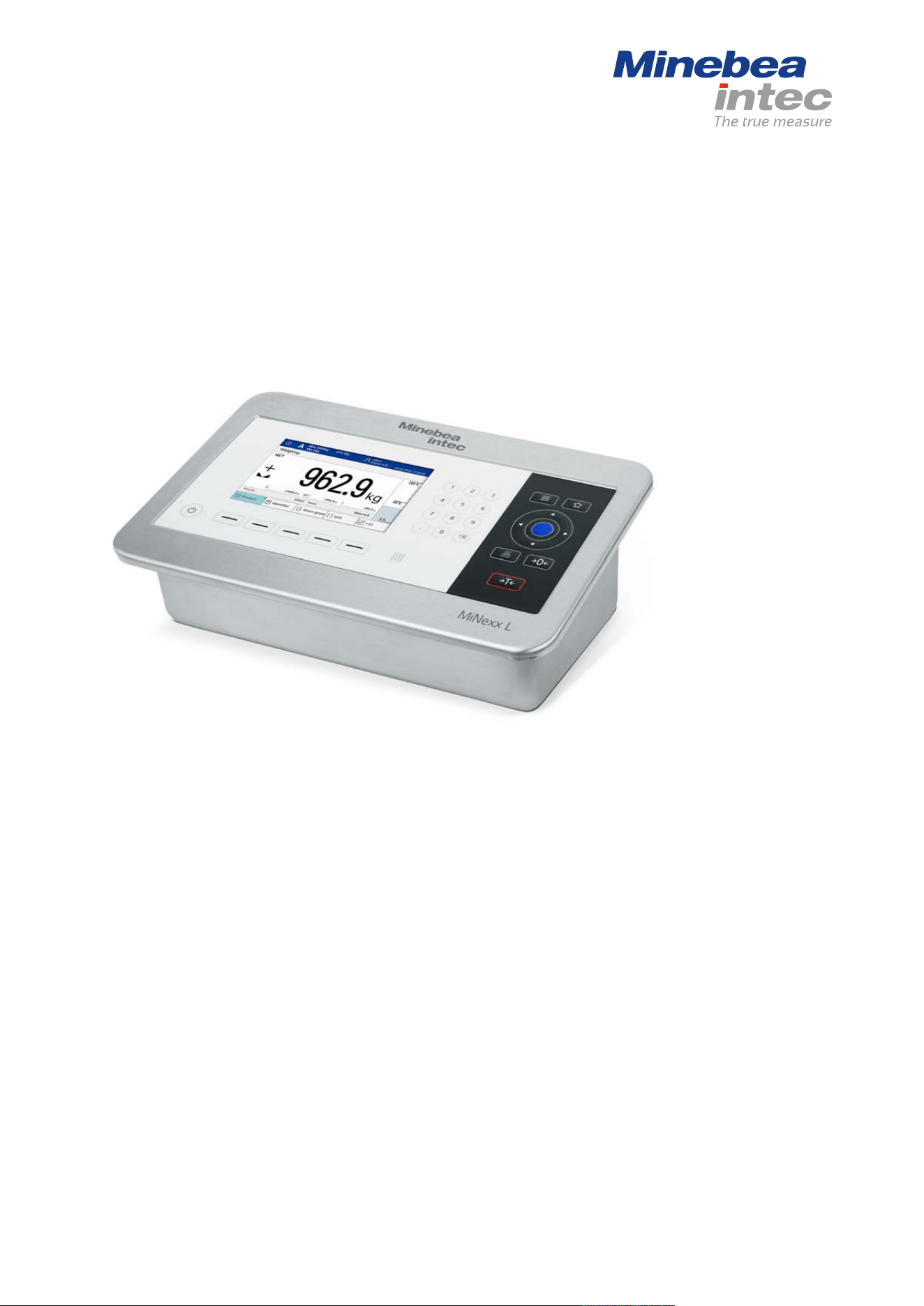
MiNexx Indicator
NICL
986283010100 Edition 0.3.0 01/12/2026
MinebeaIntec Bovenden GmbH & Co. KG, Leinetal 2, 37120 Bovenden, Germany
Phone:+49.551.309.83.0Fax:+49.551.309.83.190

Foreword
Must be followed!
Any information in this document is subject to change without notice and does not represent a
commitment on the part of MinebeaIntec unless legally prescribed. The product must only be op
erated by trained operating personnel. Installation and commissioning must only be performed
by trained specialist personnel. In correspondence concerning this product, the type, name, and
release number/serial number as well as all license numbers relating to the product must be cit
ed.
Note
This document is partially protected by copyright. It may not be changed or copied, and it may
not be used without purchasing or written permission from the copyright owner (MinebeaIntec).
The use of this product constitutes acceptance by you of the above-mentioned provisions.

Table of contents
1 Introduction ................................................................................................................................... 5
1.1 Documentation overview .......................................................................................................... 5
1.2 Read the safety instructions and the documentation ........................................................... 6
1.3 This is what instructions look like ........................................................................................... 6
1.4 This is what lists look like ......................................................................................................... 6
1.5 This is what warnings look like ................................................................................................ 6
1.6 Support ........................................................................................................................................ 7
2 Safety instructions ........................................................................................................................ 8
2.1 General instructions .................................................................................................................. 8
2.2 Intended use ............................................................................................................................... 8
2.3 Non-intended use ...................................................................................................................... 9
2.4 Exclusion of liability ................................................................................................................... 9
2.5 Target groups ............................................................................................................................. 9
2.6 Initial inspection ......................................................................................................................... 9
2.7 Before commissioning ............................................................................................................... 9
2.7.1 Installation .................................................................................................................... 10
2.7.2 Use in hazardous areas .............................................................................................. 10
2.7.3 Failure and excessive stress ....................................................................................... 11
2.7.4 For special attention ................................................................................................... 11
3 Device description ....................................................................................................................... 12
3.1 General description ................................................................................................................. 12
3.2 Hardware construction ............................................................................................................ 13
3.2.1 Device front .................................................................................................................. 13
3.2.2 Overview of connections ............................................................................................ 14
3.2.3 Internal slots ................................................................................................................ 15
3.3 Power supply and protective grounding conductor ............................................................ 16
3.3.1 Power supply version 100–240VAC .......................................................................... 16
3.3.2 Power supply version 24 V DC ................................................................................... 18
3.4 Network connection ................................................................................................................ 19
3.5 USB port .................................................................................................................................... 20
3.6 Option cards ............................................................................................................................. 22
3.6.1 General instructions .................................................................................................... 22
3.6.2 “Efficiency” analog weighing electronics board ...................................................... 22
3.6.3 “Performance” analog weighing electronics board ................................................ 26
3.6.4 Digital weighing electronics board ........................................................................... 29
3.6.5 RS‑232/485 interface ................................................................................................... 36
3.6.6 Analog inputs and outputs ........................................................................................ 43
3.6.7 Digital inputs and outputs (2 IN/4 OUT) .................................................................. 48

3.6.8 Digital inputs and outputs (4 IN/6 OUT) .................................................................. 57
3.6.9 Fieldbus modules ........................................................................................................ 63
4 Device installation ....................................................................................................................... 71
4.1 Opening/closing the device .................................................................................................... 71
4.2 Connecting the functional ground ........................................................................................ 73
4.3 Establishing connections for option cards ........................................................................... 73
4.4 Switching on the device .......................................................................................................... 73
5 Cleaning ........................................................................................................................................ 74
5.1 Instructions for cleaning ......................................................................................................... 74
5.2 Cleaning agents ....................................................................................................................... 75
6 Disposal ........................................................................................................................................ 76
7 Specification ................................................................................................................................. 77
7.1 General technical data ............................................................................................................ 77
7.1.1 display ........................................................................................................................... 77
7.1.2 Supply voltage version 100–240VAC ........................................................................ 77
7.1.3 Supply voltage version 24 V DC ................................................................................. 77
7.1.4 Buffering of the date/time module .......................................................................... 78
7.1.5 Backup batteries (for outages) .................................................................................. 78
7.1.6 NFC ................................................................................................................................ 78
7.2 Housing ..................................................................................................................................... 79
7.2.1 Housing dimensions ................................................................................................... 79
7.2.2 Materials ....................................................................................................................... 80
7.2.3 IP protection ................................................................................................................ 80
7.3 Ambient conditions .................................................................................................................. 81
7.4 Electromagnetic Compatibility (EMC) .................................................................................... 81
8 Appendix ....................................................................................................................................... 82
8.1 Certificates ................................................................................................................................ 82
8.2 Legal Information on conformity .......................................................................................... 82
8.2.1 FCC Statement ............................................................................................................. 82
8.2.2 IC Statement ................................................................................................................ 82

1. Introduction | 5
1 Introduction
1.1 Documentation overview
The full documentation can be found on the MinebeaIntec website https://
manuals.minebea-intec.com:
– Technical manual – Hardware for MinebeaIntec indicator
– Technical manual – Firmware for MinebeaIntec indicator
– Operating instructions for the application software
Technical manual – Hardware
The document describes the hardware for the MinebeaIntec indicator in
detail.
Technical manual – Firmware
The document describes the operation of the MinebeaIntec indicator in
detail.
Operating instructions for the application software
The document provides a detailed description of the operation of the
currently installed application.
1. Introduction | 1.2 - Read the safety instructions and the documentation | 6
1.2 Read the safety instructions and the documentation
The following documents are included with the MinebeaIntec product in
printed form:
– Safety instructions
Please read the safety instructions and the documentation before using the
product.
These are part of the product. Keep the safety instructions in a safe and easily
accessible location.
1.3 This is what instructions look like
1.- n. are placed before steps that must be done in sequence.
is placed before a step.
describes the result of a step.
1.4 This is what lists look like
– indicates an item in a list.
1.5 This is what warnings look like
Signal words indicate the severity of the danger involved if measures for pre
venting hazards are not followed.
DANGER
Warning of personal injury
DANGER indicates that death or severe, irreversible personal
injury will occur if appropriate safety measures are not observed.
Take appropriate safety measures.
WARNING
Warning of a hazard area and/or risk of personal injury
WARNING indicates that death or severe, irreversible injury may
occur if appropriate safety measures are not observed.
Take appropriate safety measures.

1. Introduction | 1.6 - Support | 7
CAUTION
Warning of personal injury.
CAUTION indicates that minor, reversible injury may occur if
appropriate safety measures are not observed.
Take appropriate safety measures.
NOTICE
Warning of damage to property and/or the environment.
NOTICE indicates that damage to property and/or the environment may
occur if appropriate safety measures are not observed.
Take appropriate safety measures.
Note: User tips, useful information, and notes.
1.6 Support
Telephone Bovenden: +49.551.30983.111
Telephone Hamburg: +49.40.67960.444
Email: [email protected]

2. Safety instructions | 8
2 Safety instructions
2.1 General instructions
The device complies with the directives and standards on electrical equip
ment, electromagnetic compatibility, and the prescribed safety requirements.
However, improper use can cause injury to persons and damage to property.
The device was in perfect condition with regard to safety features when it left
the factory.
– To maintain this condition and to ensure safe operation, the user must
follow the instructions and observe the warnings in this manual.
2.2 Intended use
The device is exclusively intended for use in weighing and dosing systems,
and is particularly suitable for tank and vessel scales, truck scales, platform
scales, crane scales, dosing systems and as a weight indicator in intelligent
control systems.
Installation must only be performed by trained electricians.
Device maintenance and commissioning must only be performed by trained
specialists.

2. Safety instructions | 2.3 - Non-intended use | 9
2.3 Non-intended use
The indicator must only be used as intended in order to prevent malfunctions
and faults.
2.4 Exclusion of liability
The device reflects the state of the art.
No warranty is given that the device is free of faults, especially not in conjunc
tion with third-party software and hardware components required for opera
tion.
The manufacturer does not accept any liability for damage caused by third-
party system components and/or due to incorrect use of the device. The use
of this device signifies recognition of the stipulations listed above.
2.5 Target groups
Trained specialists
Employees that perform the commissioning and maintenance of the
weighing technology and have received comprehensive training therein.
Trained electricians
Employees that perform the installation of the weighing technology and have
received comprehensive training therein.
2.6 Initial inspection
Check the contents of the consignment for completeness. Inspect the
contents visually to determine whether any damage has occurred during
transport.
If there are grounds for rejection of the goods, a claim must be filed with the
carrier immediately. A MinebeaIntec sales or service organization must also
be notified.
2.7 Before commissioning

2. Safety instructions | 2.7 - Before commissioning | 10
Before commissioning, as well as after storage or transport, inspect the de
vice visually for signs of mechanical damage.
– The device should not be put into operation if it displays signs of visible
damage and/or is defective.
2.7.1 Installation
The device must be installed in an EMC-compliant manner.
To ensure proper cooling of the device, make sure air circulation around the
device is not blocked. Always maintain a distance of at least 10cm. Avoid ex
posing the instrument to excessive heat, e.g., from direct sunlight and vibra
tions. The ambient conditions specified under Ambient conditions must be
taken into account at all times.
2.7.2 Use in hazardous areas
The NICL indicator must not be used in hazardous areas.
The NICL indicator must not be used in hazardous areas.

2. Safety instructions | 2.7 - Before commissioning | 11
2.7.3 Failure and excessive stress
If safe operation of the device no longer appears to be possible, shut it down
and make sure it cannot be used.
Safe operation is no longer ensured if any of the following is true:
– The device is physically damaged.
– The device has been incorrectly connected.
– The device has been operated with the incorrect supply voltage.
– The device has been subjected to stresses beyond the tolerance limits
(e.g., during storage or transport).
2.7.4 For special attention
All inputs and outputs (with the exception of supply voltage) must be
supplied via SELV/PELV – Limited Energy of UL-CSA-IEC EN 61010-1or Limited
Power Source of UL-CSA-EN IEC 62368-1.
Make sure that the construction of the device is not altered to the detriment
of safety. In particular, the leakage paths, safety distances (parts leading
from the supply voltage) and clearances must not be impaired in any way.
MinebeaIntec cannot be held responsible for personal injury or property
damage caused by a device being repaired incorrectly by an operator or
installer.

3. Device description | 12
3 Device description
3.1 General description
MiNexx NICL is a weight indicator in a table-top housing.
A maximum of three scales can be connected.
The device is equipped with a TFT color display for the display, and a keypad
(membrane keypad) for operation.
The keypad and the display form one unit with the front.
The cables for the supply voltage, interfaces, etc. are connected at the back of
the housing via M12 connectors or through cable glands.
There are various option cards available, which can be integrated into
the device (maximum of 5) as required. The type of option card installed
determines the connections available and their assignment.
3. Device description | 3.2 - Hardware construction | 13
3.2 Hardware construction
3.2.1 Device front
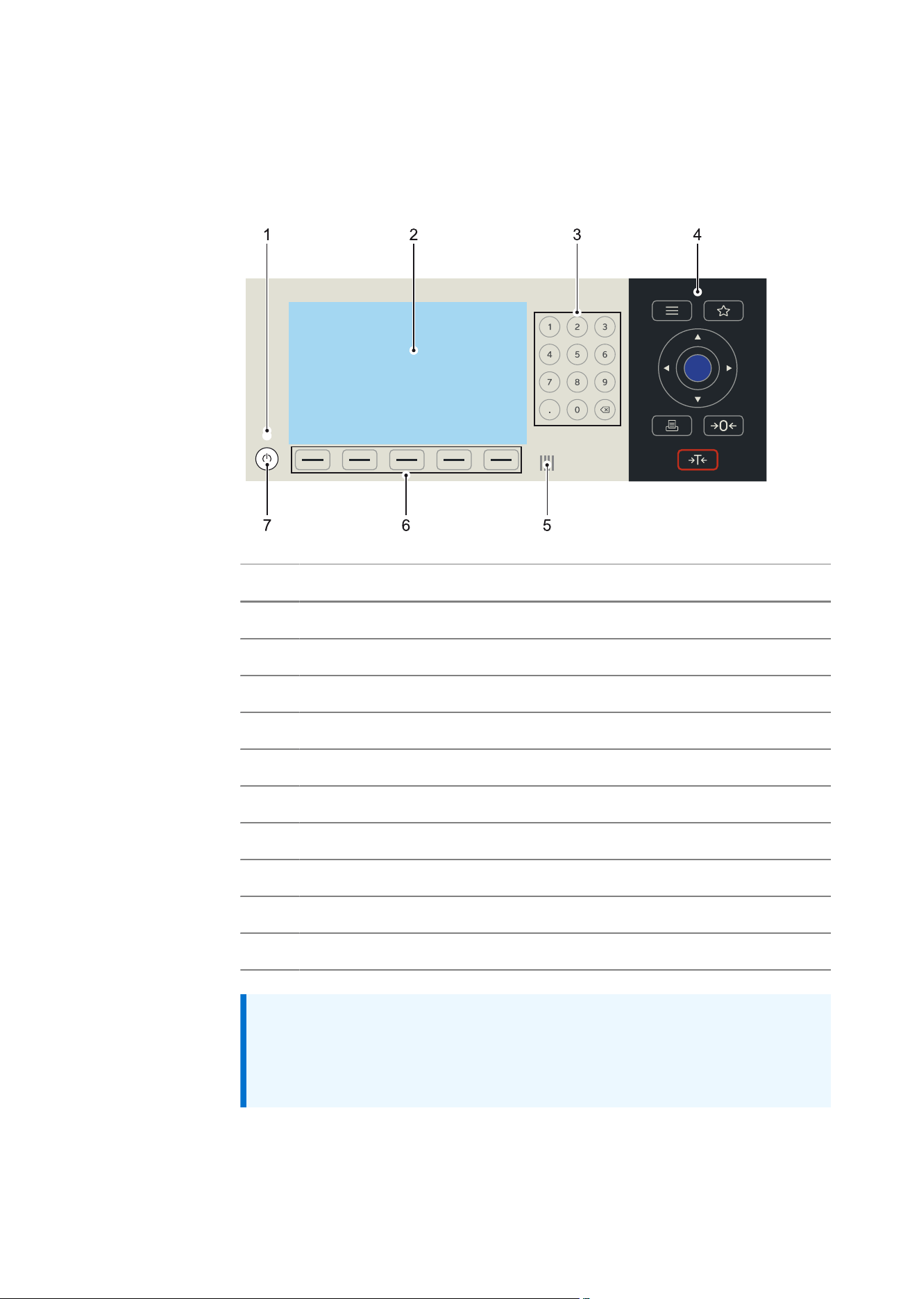
Pos. Name
Display elements
1 Power LED
2 TFT color display 5.0"
Operating elements
3 Numpad
4 Keypad
6 Soft keys
7 On/off button
Other
5 NFC
Note:
The device front can be installed in two directions. For wall mounting, the
underside of the display points in the direction of the cable glands. When
using as a table-top device, it is rotated 180°.
3. Device description | 3.2 - Hardware construction | 14
3.2.2 Overview of connections
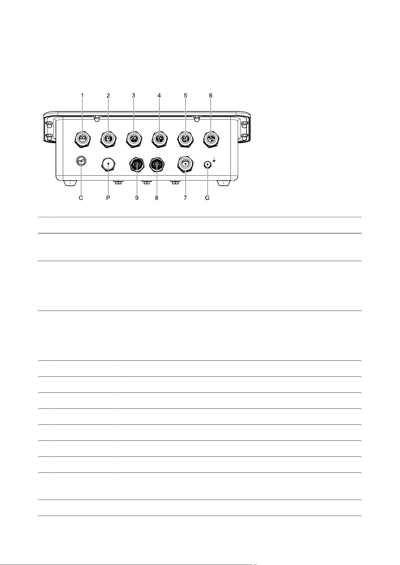
The following connection options are located on the back of the device:
Pos. Cable gland Function Connection
1 M16 or
M20 (bored)
Analog weighing electron
ics board (in slot 1)
Open cable ends or cable according to or
dering option
2 M16 or
M20 (bored)
Analog weighing electron
ics board or digital weigh
ing electronics board or op
tion card in slot 2
Open cable ends or cable according to or
dering option
3 M16 Analog weighing electron
ics board or digital weigh
ing electronics board or op
tion card in slot 3
M12 or cable according to ordering option
4 M16 Option card in slot 4 M12 or cable according to ordering option
5 M16 Ethernet M12 or cable according to ordering option
6 M16 Power supply Open cable ends
7 M16 Fieldbus 1 M12 or cable according to ordering option
8 M16 Fieldbus 2 or USB 2 M12 or cable according to ordering option
9 M16 USB 1 M12 or cable according to ordering option
C Menu lock switch (CAL-1)
P Pressure compensation ele
ment
G Functional ground
3. Device description | 3.2 - Hardware construction | 15
If there is no option available for a connection position, the position is sealed
at the factory with a blanking plug.
Note:
When using cable glands, the cables can be run through cable glands that
correspond to the relevant cable diameter.
3.2.3 Internal slots
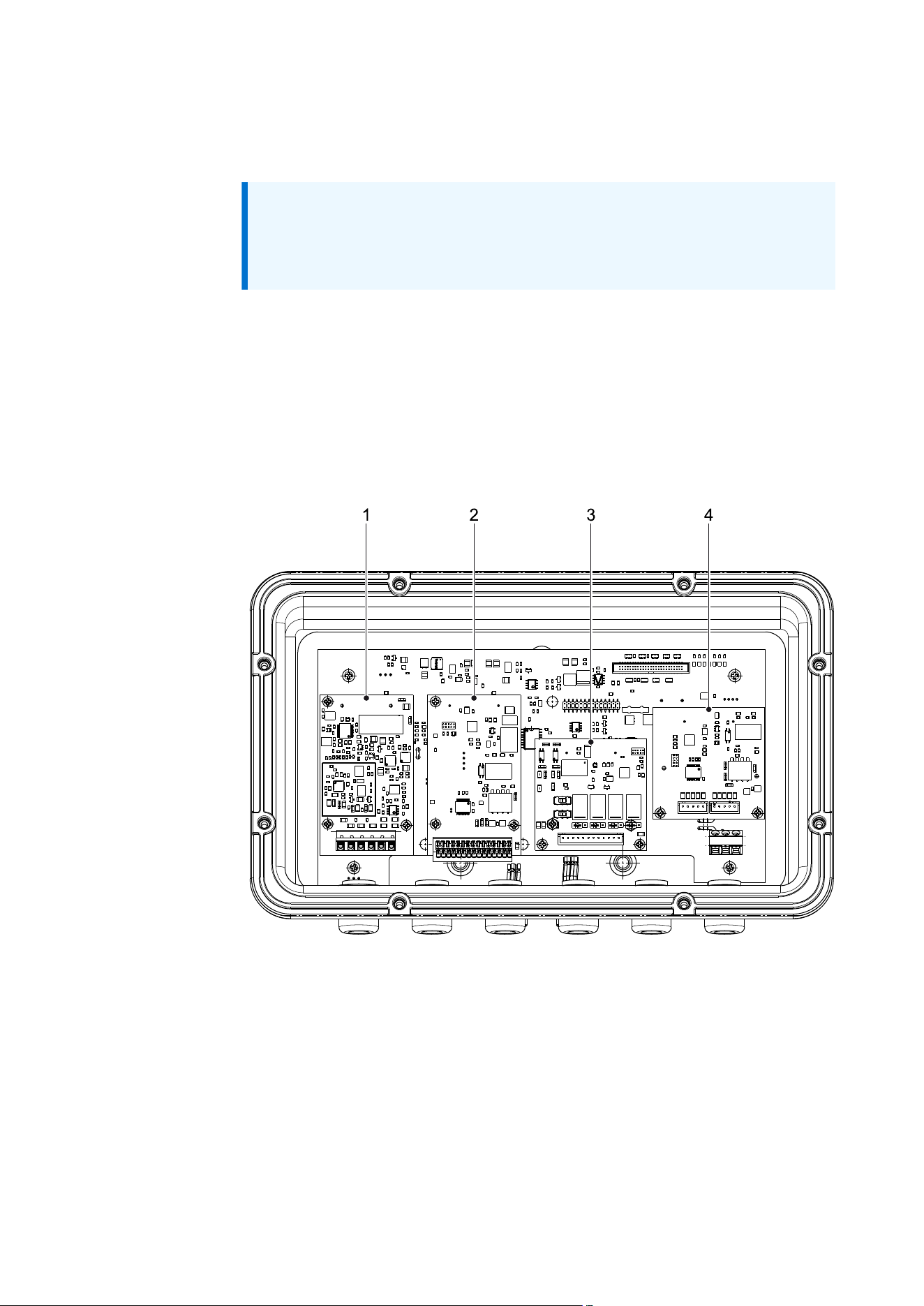
The device has 5 internal slots:
– Slots 1…4 on the top
– FB slot for fieldbus on the bottom
Slots 1…4 are shown in the following diagram:

3. Device description | 3.3 - Power supply and protective grounding conductor | 16
The slots can be used for Option cards as follows:
Option card/slot 1 2 3 4 FB
Analog weighing electronics board ✘ ✘
Digital weighing electronics board ✘ ✘ ✘
Interface RS‑232/485 ✘ ✘ ✘
Analog inputs and outputs ✘ ✘
Digital inputs and outputs (2 IN/4 OUT) ✘ ✘ ✘
Digital inputs and outputs (4 IN/6 OUT) ✘ ✘ ✘
Fieldbus module ✘
Note:
xBPI scales are connected to the digital weighing electronics board.
It is not possible to connect to the option card RS-232/485 (option C2/C3/
C4 for RS-232, DA2/DA3/DA4 or DB2/DB3/DB4 for RS-485).
3.3 Power supply and protective grounding conductor
3.3.1 Power supply version 100–240VAC
Inside the device, the 100–240 V AC power supply is connected via a 3‑pin
terminal strip, which is located on the device’s mainboard. According to the
selected ordering option, a cable is connected for this purpose and routed
out of the device through position 6 (see Overview of connections).
The device is protected (primary side) via two fuses and is equipped with a
wide range power supply.
The power supply is protected against short circuits and overloads, and
disconnects automatically in case of a fault.
Note:
For technical data, see Supply voltage version 100–240VAC.
Protective grounding conductor
The protective grounding conductor PE is connected to the device in the
housing.

3. Device description | 3.3 - Power supply and protective grounding conductor | 17
Option: open cable ends (L10)
Pin assignment
Wire color Code Name Description
Blue bu N Neutral conductor
Yel
low-green
ye-gn PE Protective grounding con
ductor/functional ground
Brown bn L Live conductor
Note:
– An external disconnecting device (power switch) must be provided
and easy to reach.
– The disconnecting device must be rated for the input current of the
device.
– A back-up fuse with maximum 16A is required.
Option: power plug (EU, GB, US, CH, DK, IT)
Note:
– The power plug must be easy to reach.
– To disconnect the device from the power supply, remove the plug con
nector.

3. Device description | 3.3 - Power supply and protective grounding conductor | 18
3.3.2 Power supply version 24 V DC
The 24 V DC power supply is connected inside the device via a 3-pin terminal
strip, which is located on the device’s mainboard. According to the selected
ordering option, a cable is connected for this purpose and routed out of the
device through position 6 (see Overview of connections).
The device is protected (primary side) via two fuses and against incorrect
polarity.
Note:
The device may only be operated with a 24V power supply that meets the
following requirements:
“Class 2 of NEC or SELV/PELV – Limited Energy of UL-CSA-IEC EN
61010-1or Limited Power Source of UL-CSA-EN IEC 62368-1”
Note:
For technical data, see Supply voltage version 24 V DC.
Protective grounding conductor
The protective grounding conductor PE is connected to the device in the
housing.
Option: open cable ends (L20)
Pin assignment
Wire color Code Name Description
Blue bu + +24VDC
Yel
low-green
ye-gn PE Protective grounding con
ductor/functional ground
Brown bn GND GND
Note:
– An external disconnecting device (power switch) must be provided
and easy to reach.
– The disconnecting device must be rated for the input current of the
device.
3. Device description | 3.4 - Network connection | 19
3.4 Network connection
The device contains an Ethernet interface, which can be optionally routed out
of the device through position 5 (see Overview of connections).
Technical data
Name Data
Connection
Position 5
M12 plug connector, female (B10)
M16 cable gland:
– Cable to RJ45 plug connector
(B11)
Transfer rate (baud rate) Auto-detection:
10Mbps or 100Mbps, full or half du
plex
Electrical isolation Yes
Cable type Minimum CAT5, screened
Max. cable length 100 m
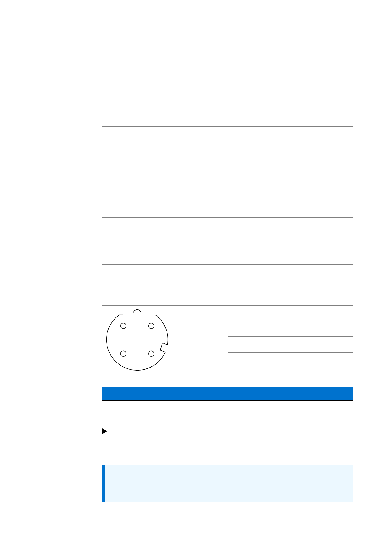
Pin assignment M12 plug connector, female (option B10)
Plug connector, female D-coded Pin Signal
1 TD+
2 RD+
3 TD-
4
3
1
2
4 RD-
NOTICE
IT operations halted due to corrupted data.
Protect the network against unauthorized access.
Always observe the Chapter “Network security” in the Technical manual –
Firmware.
Note:
For information on setting up the network, see “Network settings” in the
Technical manual – Firmware.

3. Device description | 3.5 - USB port | 20
3.5 USB port
The device contains two USB interfaces, which can be optionally routed
out of the device through position 8 and 9 (see Overview of connections).
Furthermore, the function of the USB interfaces is determined by the selected
ordering option.
Interface Host function Device function
USB 1 U1H U2H U1D
USB 2 – U2H –
Technical data
Name Data
Connection USB 1
Position 9
M12 plug connector, female (U10)
M16 cable gland:
– Cable to USB-A plug connector,
female (U11)
Connection USB 2
Position 8
Host function only
M12 plug connector, female (U20)
M16 cable gland:
– Cable to USB-A plug connector,
female (U21)
Max. current I
max
= 200 mA;
protected against short circuit
Max. cable length 2 m
Pin assignment M12 plug connector, female (option U10, U20)
Plug connector, female B-coded Pin Signal Name
1 D+ Data +
2 D- Data -
3 VBUS +5VDC
4 GND Ground
4
3
1
2
5
5 – –

3. Device description | 3.5 - USB port | 21
Note:
The suspend function (see Chapter “Operating & display” in the Technical
manual – Firmware) cannot be guaranteed if a load that requires a
current of >200mA is connected by USB.
Furthermore, exceeding the maximum current may damage the device
and cause it to malfunction.

3. Device description | 3.6 - Option cards | 22
3.6 Option cards
3.6.1 General instructions
The options must only be operated with SELV/PELV energy/power limitation.
Note:
The device may only be operated with a 24V power supply that meets the
following requirements:
“Class 2 of NEC or SELV/PELV – Limited Energy of UL-CSA-IEC EN
61010-1or Limited Power Source of UL-CSA-EN IEC 62368-1”
3.6.2 “Efficiency” analog weighing electronics board
The analog weighing electronics board is required to connect a scale to DMS
load cells.
The connection to the “Efficiency” weighing electronics board can be made
using a cable of max. 10 m length.
For this purpose, software is used to set up a weighing point in the device.
The calibration data and parameters for the weighing point are permanently
stored in the EAROM (non-volatile memory).
Note:
The load cells can be powered externally. In this case, only the sense and
measurement lines are connected to the plug connector.
Note: For information on setting up the weighing point, see Chapter
“Analog weighing point” in the Technical manual – Firmware.
3. Device description | 3.6 - Option cards | 23
Technical data
Name Data
Load cell supply U
DC
=±5V
Measuring input signal range 0mV…30mV
Smallest permissible input
signal per verification scale
interval*
0.44µV/e (class 3); 1µV/e (class 4)
Max. quantity of verification
scale intervals*
10,000 (class 3); 1000 (class 4)
Load cell impedance range 75…1200Ω
Fraction of the error limit 0.5
Cable length in relation to ca
ble cross section*
≤110m/mm
2
(class 3)
≤1000m/mm
2
(class 4)
Max. voltage at sense input U
DC
=5V with monitoring
Electrical isolation no
*Class relevant for verification requirements
Connections
Connection
Position 1
M16 cable gland:
– Internal terminal strip (WA12)
– Cable to 12-pin round socket (WA11)

3. Device description | 3.6 - Option cards | 24
Name Data
M20 cable gland:
– Internal terminal strip (WA13)
Screen connection in the cable gland
Connection
Position 2
M16 cable gland:
– Internal terminal strip (WA22)
– Cable to 12-pin round socket (WA21)
M20 cable gland:
– Internal terminal strip (WA23)
Screen connection in the cable gland
Connection of connec
tion/load cell cable
6-wire or 4-wire (with additional bridges)
Cable(s) See accessory documentation
Absolute maximum ratings
Sense voltage ±14V (±7V)
Note:
Loads that exceed the values specified under “absolute maximum rat
ings,” can cause permanent damage to the device. The function and relia
bility of the device cannot be guaranteed if it is used under different con
ditions than those specified under “Technical data.”
3. Device description | 3.6 - Option cards | 25
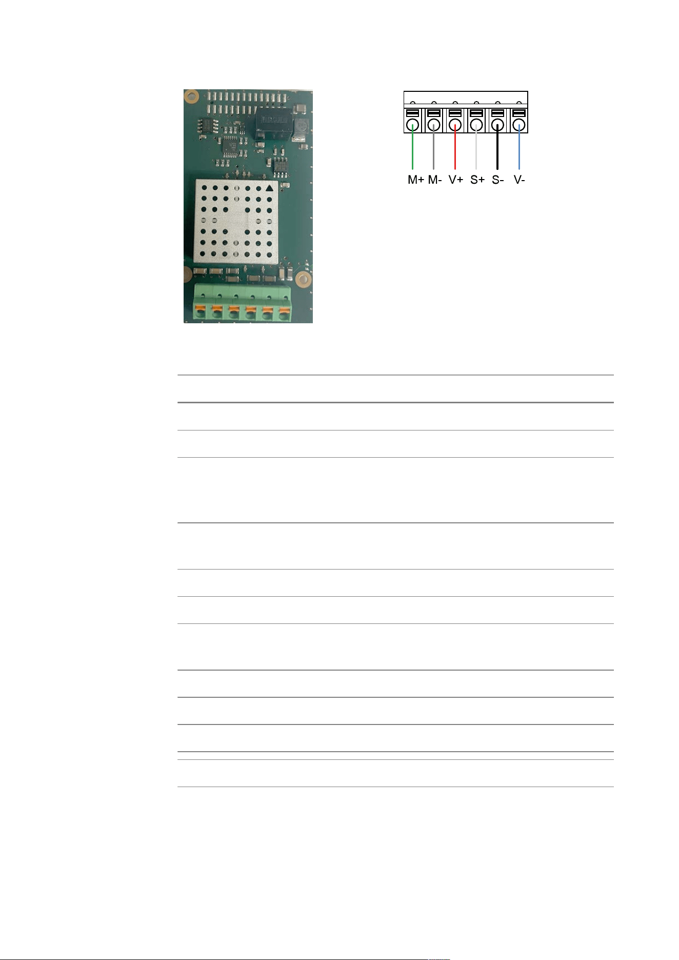
Pin assignment terminal strip (option WA12/WA13, WA22, WA23)
Terminal Signal Connection Description Wire color
MinebeaIntec
1 M+ + Meas. + Signal/LC output green
2 M- – Meas. – Signal/LC output gray
3 V+ + Supply + Supply/excitation red
4 S+ + Sense + Sense white
5 S- – Sense – Sense black
6 V- – Supply – Supply/excitation blue
Note:
Do not shorten the load cell cable. Connect the prepared cable end and
roll up the remaining cable.
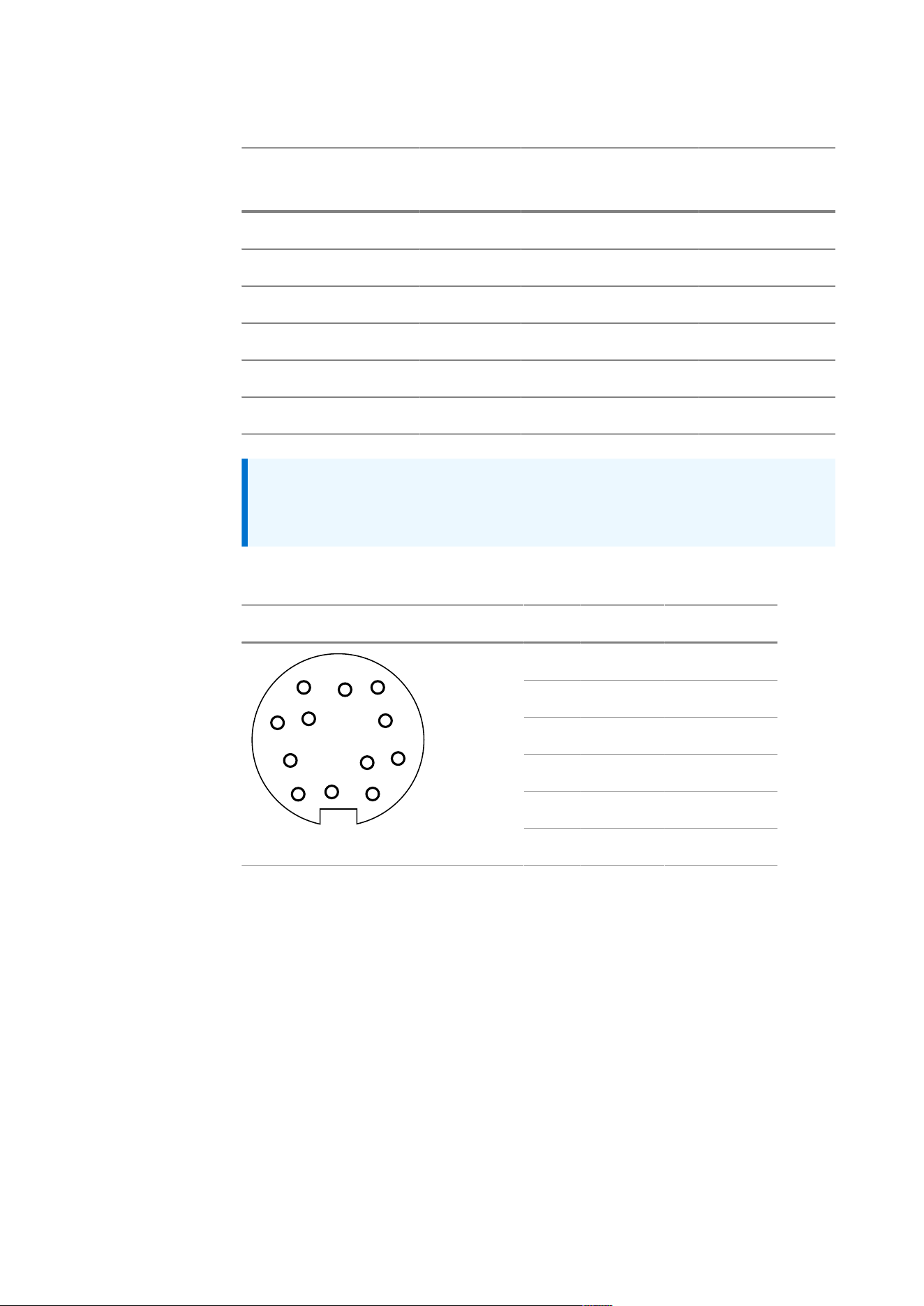
Pin assignment 12-pin round socket (option WA11, WA21)
Plug connector, female Pin Signal Connection
B S+ + Sense
C V+ + Supply
D V- – Supply
E S- – Sense
H M- – Meas.
E
F
G
D
M
H
C
L
J
B
A
K
J M+ + Meas.
3. Device description | 3.6 - Option cards | 26
3.6.3 “Performance” analog weighing electronics board
The analog weighing electronics board is required to connect a scale to DMS
load cells.
The connection to the “Performance” weighing electronics board can be
made using long cables, see Technical data.
For this purpose, software is used to set up a weighing point in the device.
The calibration data and parameters for the weighing point are permanently
stored in the EAROM (non-volatile memory).
Note:
The load cells can be powered externally. In this case, only the sense and
measurement lines are connected to the plug connector.
Note: For information on setting up the weighing point, see also Chapter
“Analog weighing point” in the Technical manual – Firmware.
Technical data
Name Data
Load cell supply voltage U
DC
=10V (±5V) internal supply
U
DC
=12V (±6V) external supply
Measuring input signal range 0mV…30mV
Smallest permissible input
signal per verification scale
interval
0.5µV/e

3. Device description | 3.6 - Option cards | 27
Name Data
Max. quantity of verification
scale intervals
10,000 (class 3); 1000 (class 4)
(Class relevant for verification requirements)
Load cell impedance range 75…1200Ω
Fraction of the error limit 0.5 (relevant for verification requirements)
Cable length in relation to ca
ble cross section
≤1000m/mm
2
Max. voltage at sense input U
DC
=±6V
Electrical isolation Yes
Connections
Connection
Position 1
M16 cable gland:
– Internal terminal strip (WA12)
– Cable to 12-pin round socket (WA11)
M20 cable gland:
– Internal terminal strip (WA13)
Screen connection in the cable gland
Connection
Position 2
M16 cable gland:
– Internal terminal strip (WA22)
– Cable to 12-pin round socket (WA21)
M20 cable gland:
– Internal terminal strip (WA23)
Screen connection in the cable gland
Connection of connec
tion/load cell cable
6-wire or 4-wire (with additional bridges)
Cable(s) See accessory documentation
Absolute maximum ratings
Sense voltage ±14V (±7V)
3. Device description | 3.6 - Option cards | 28
Note:
Loads that exceed the values specified under “absolute maximum
ratings,” can cause permanent damage to the device. The function and
reliability of the device cannot be guaranteed if it is used under different
conditions than those specified under “Technical data.”
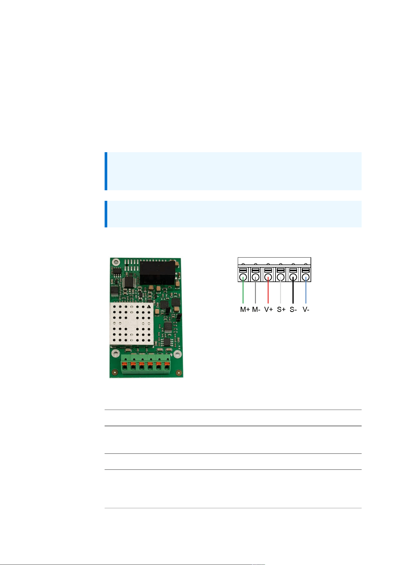
Pin assignment terminal strip (option WA12/WA13, WA22, WA23)
Terminal Signal Connection Description Wire color
MinebeaIntec
1 M+ + Meas. + Signal/LC output green
2 M- – Meas. – Signal/LC output gray
3 V+ + Supply + Supply/excitation red
4 S+ + Sense + Sense white
5 S- – Sense – Sense black
6 V- – Supply – Supply/excitation blue
Note:
Do not shorten the load cell cable. Connect the prepared cable end and
roll up the remaining cable.
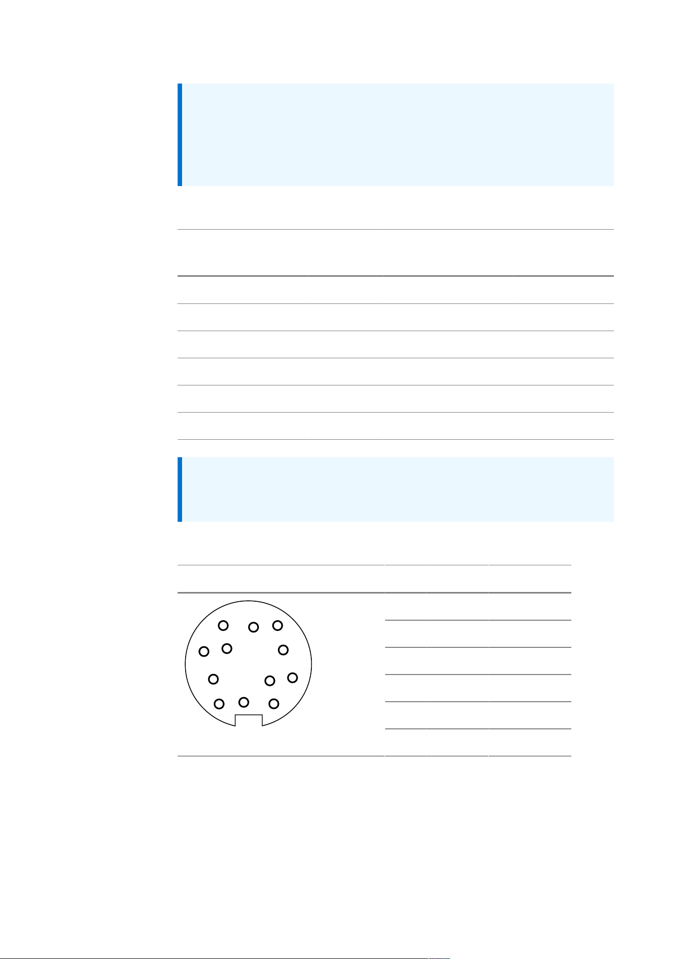
Pin assignment 12-pin round socket (option WA11, WA21)
Plug connector, female Pin Signal Connection
B S+ + Sense
C V+ + Supply
D V- – Supply
E S- – Sense
H M- – Meas.
E
F
G
D
M
H
C
L
J
B
A
K
J M+ + Meas.
3. Device description | 3.6 - Option cards | 29
3.6.4 Digital weighing electronics board
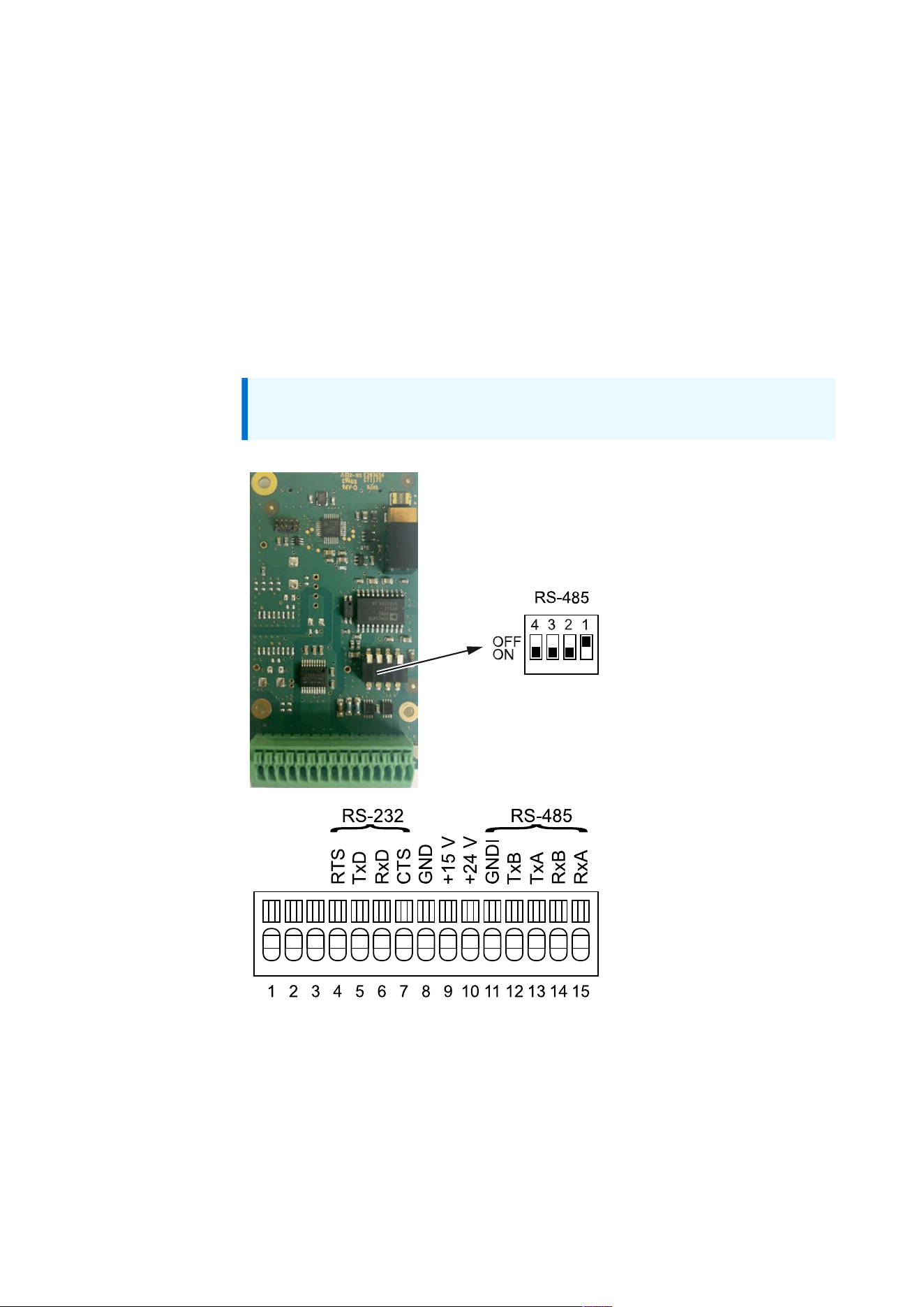
The digital weighing electronics board is required to connect a digital
weighing platform with xBPI protocol.
For this purpose, software is used to set up a weighing point in the device.
The digital weighing electronics board must only be connected using cables
that remain within the building and are less than 30m long.
The weighing platform is connected via RS-232 or RS-485.
Furthermore, the digital weighing electronics board provides a 15V and 24V
power supply for the weighing platform.
Note: See also, Chapter“Digital weighing point (xBPI)” in the Technical
manual – Firmware

3. Device description | 3.6 - Option cards | 30
Technical data
Name Data
RS-232
Number of channels 1
Signals Input: RxD, CTS
Output: TxD, RTS
Reference potential GND
Electrical isolation no
Configuration Full duplex
Transfer rate (baud
rate)
1200…115.200 bit/s
Input signal level Logic 1 (high) -3… -15V
Logic 0 (low) +3 to… +15 V
Output signal level ±5.4V typ.
RS-485
Number of channels 1
Signals TxA, RxA, TxB, RxB
Reference potential GNDI
Electrical isolation Yes
Configuration Half duplex (2-wire)
Terminating resistor The bus is terminated.
Transfer rate (baud
rate)
1200…115.200 bit/s
Signal level Logic 1 (high) 2.4… 3.3V
Logic 0 (low) 0… 0.9 V
Power supply
Voltage 15 V, 24 V, Selv/Pelv
Current 0.2A @ 15V
0.125A @ 24V
Reference potential GND

3. Device description | 3.6 - Option cards | 31
Name Data
Connections
Connection
Position 1
M12 plug connector, female (WDI11)
M16 cable gland:
– Cable to 12-pin round socket RS-232/RS-485
(WDI14/WDI15)
Screen connection in the cable gland
Connection
Position 2
M12 plug connector, female (WDI21)
M16 cable gland:
– Cable to 12-pin round socket RS-232/RS-485
(WDI24/WDI25)
Screen connection in the cable gland
Connection
Position 3
M12 plug connector, female (WDI31)
M16 cable gland:
– Cable to 12-pin round socket RS-232/RS-485
(WDI34/WDI35)
Screen connection in the cable gland
3. Device description | 3.6 - Option cards | 32
Name Data
Absolute maximum ratings
Current @ 24 V 0.5 A
Current @ 15 V 0.5 A
Input signal RS-232 ±25V
Signals RS-485 -9V…+14V
Note:
Loads that exceed the values specified under “absolute maximum
ratings,” can cause permanent damage to the device. The function and
reliability of the device cannot be guaranteed if it is used under different
conditions than those specified under “Technical data.”
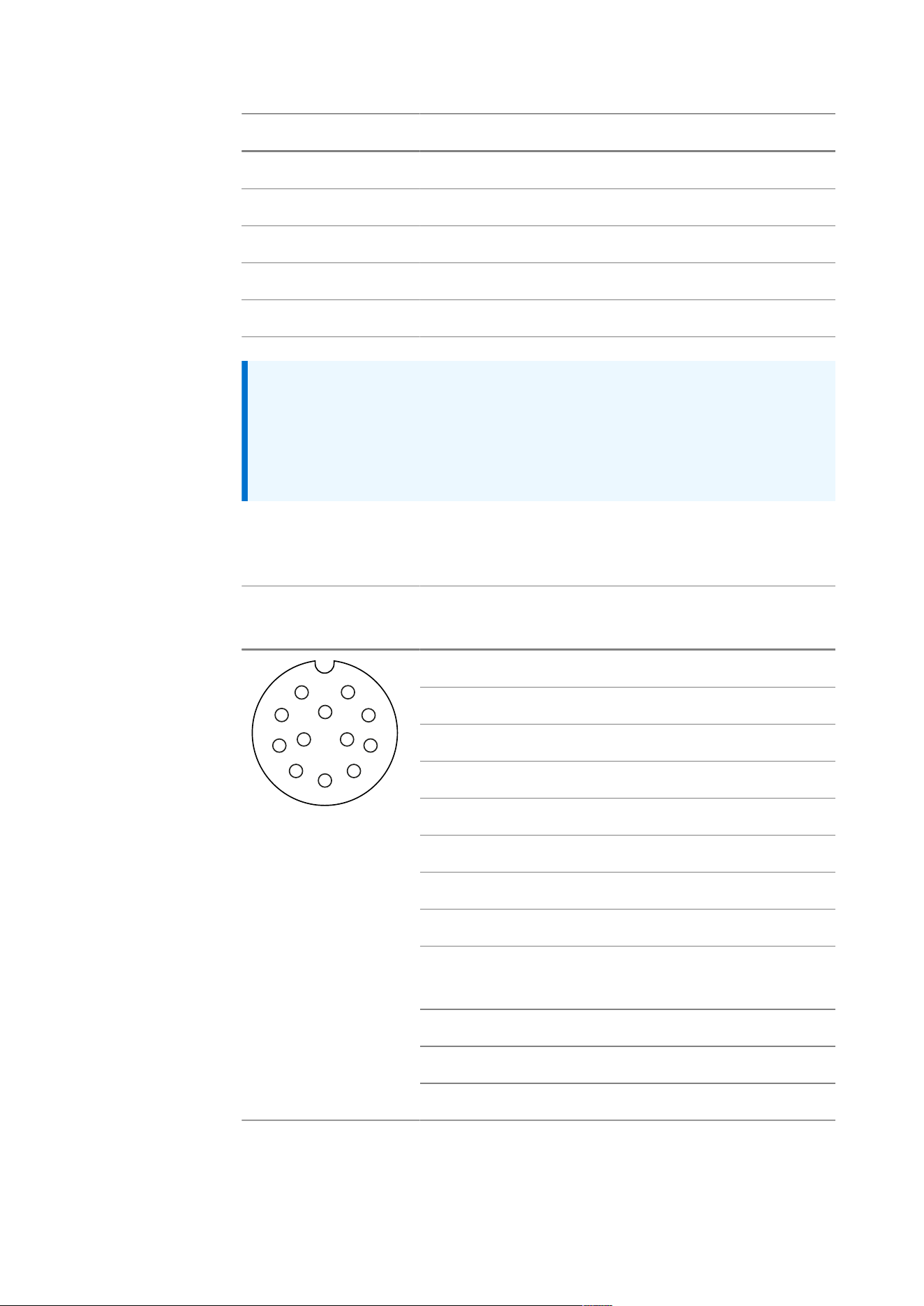
Pin assignment M12 plug connector, female (option WDI11, WDI21,
WDI31)
Plug connector, fe
male A-coded
Pin RS-232 RS-485 IS scale
1 – TxA RxD-TxD-N
2 RxD – –
3 TxD – –
4 CTS – –
5 RTS –
6 – – –
7 GND GND GND line
8 GNDI GNDI GND-ISO
9 15 V 15 V 15 V DC sup
ply
10 – TxB RxD-TxD-P
11 – – –
8
10
1
2
3
7
6
4
9
5
12
11
12 – – –

3. Device description | 3.6 - Option cards | 33
Pin assignment 12-pin round socket option (WDI14/WDI15, WDI24/
WDI25, WDI34/WDI35)
Plug connector, fe
male
Pin RS-232 RS-485 IS scale
A – TxA RxD-TxD-N
B RxD – –
C TxD – –
D CTS – –
E GNDI GNDI GND-ISO
F – –
G 15 V 15 V 15 V DC sup
ply
H RTS – –
J GND GND GND line
K GND GND GND line
L – TxB RxD-TxD-P
E
F
G
D
M
H
C
L
J
B
A
K
M 15 V 15 V 15 V DC sup
ply
3. Device description | 3.6 - Option cards | 34
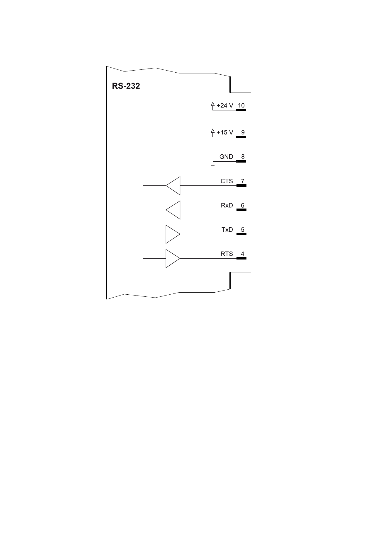
Block diagram RS-232
3. Device description | 3.6 - Option cards | 35
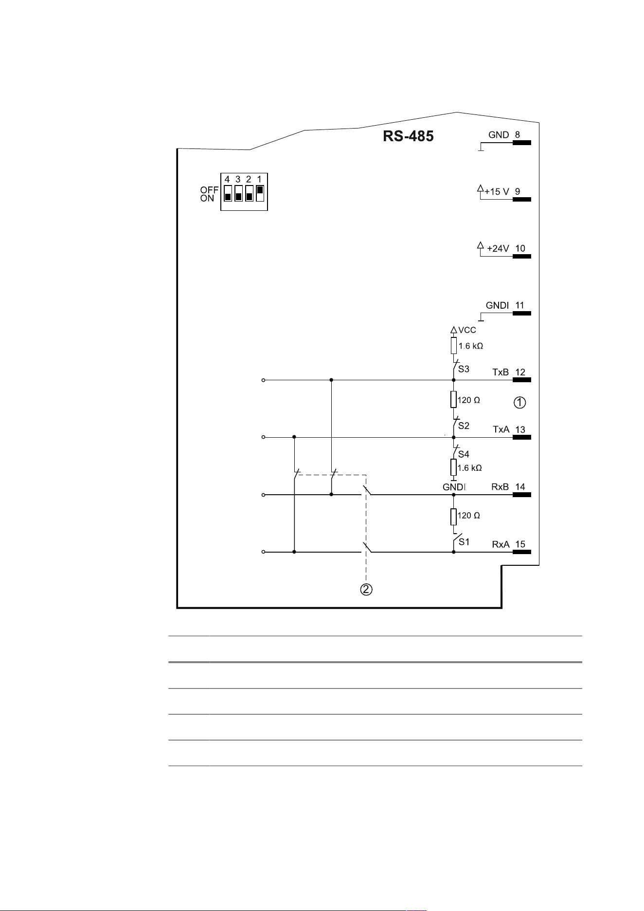
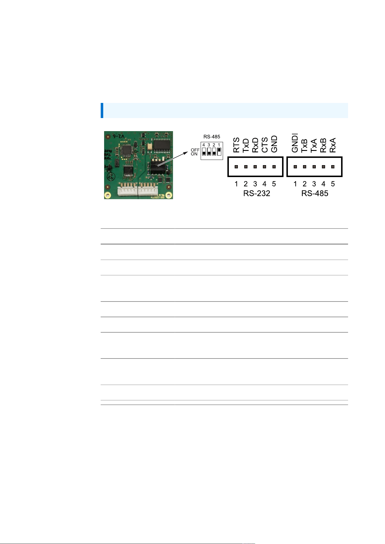
Block diagram RS-485
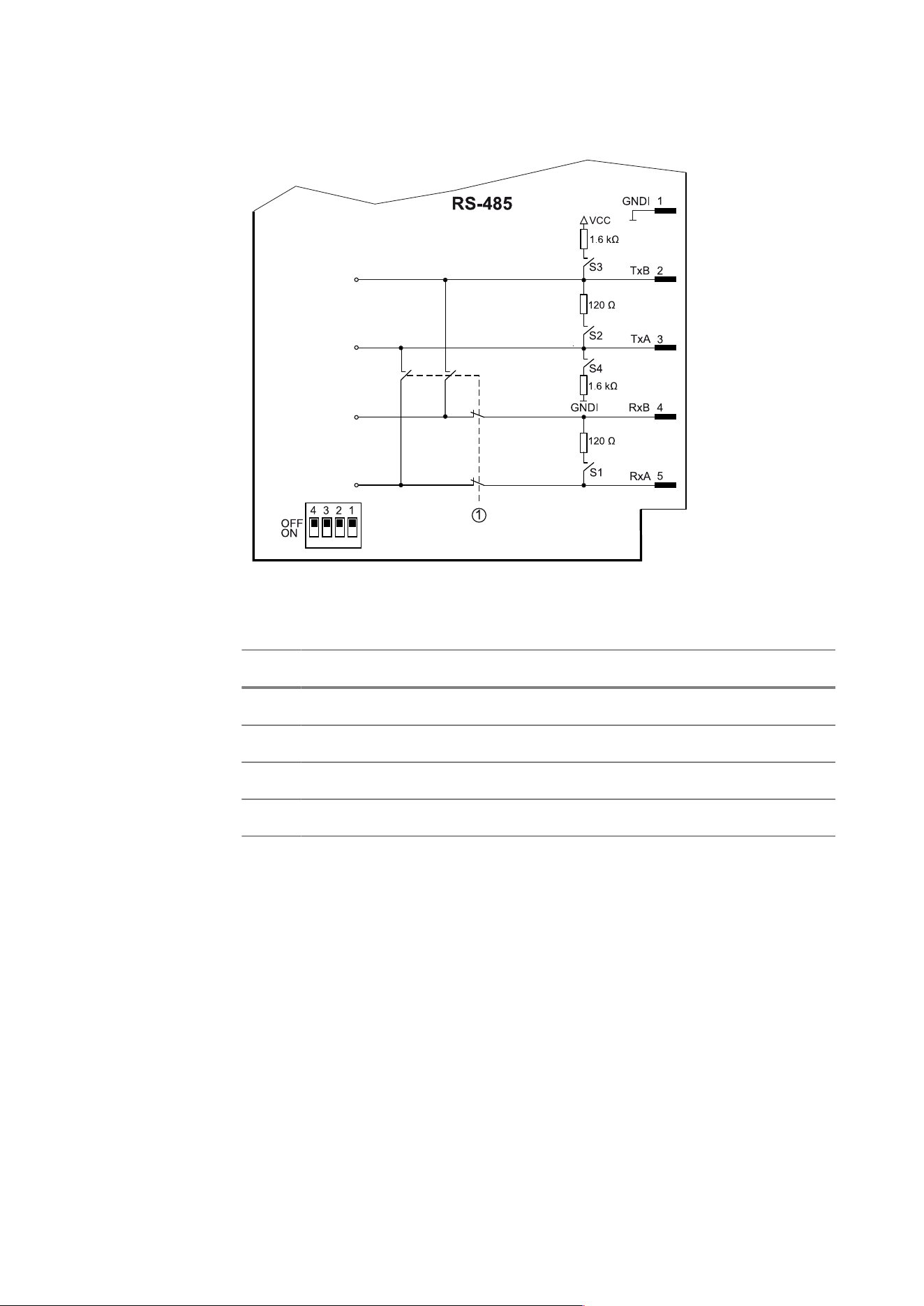
S Function Settings for RS‑485 switch
1 Rx bus termination (4-wire) OFF (switch up)
2 Tx bus termination ON (switch down)
3 TxB pull-up resistor ON (switch down)
4 TxA pull-down resistor ON (switch down)
3. Device description | 3.6 - Option cards | 36
3.6.5 RS‑232/485 interface
The option card has one RS-232 and RS-485 interface that can be used at the
same time. It is not possible to connect digital weighing platforms or load
cells.
Note: See also Chapter “Interfaces” in the Technical manual – Firmware.
Technical data
Name Data
RS-232
Number of channels 1
Signals Input: RxD, CTS
Output: TxD, RTS
Electrical isolation no
Configuration Full duplex
Transfer rate (baud
rate)
1200…115.200 bit/s
Input signal level Logic 1 (high) -3… -15V
Logic 0 (low) +3 to… +15 V
Output signal level ±5.4V typ.

3. Device description | 3.6 - Option cards | 37
Name Data
RS-485
Number of channels 1
Signals TxA, RxA, TxB, RxB
Electrical isolation Yes
Configuration Full duplex (4-wire)
Half duplex (2-wire)
Terminating resistor Can be set via DIP switch, see block diagrams.
Transfer rate (baud
rate)
1200…115.200 bit/s
Signal level Logic 1 (high) 2.4… 3.3V
Logic 0 (low) 0… 0.9 V
Connections
Connection
Position 2
M12 plug connector, female (C20, D20)
M16 cable gland:
– Cable to D-sub plug connector, 9-pin (C21, D21)
– Cable to D-sub plug connector, female, 9-pin
(C22, D22)
– Open cable ends (C23, D23)
Screen connection in the cable gland
Connection
Position 3
M12 plug connector, female (C30, D30)
M16 cable gland:
– Cable to D-sub plug connector, 9-pin (C31, D31)
– Cable to D-sub plug connector, female, 9-pin
(C32, D32)
– Open cable ends (C33, D33)
Screen connection in the cable gland
3. Device description | 3.6 - Option cards | 38
Name Data
Connection
Position 4
M12 plug connector, female (C40, D40)
M16 cable gland:
– Cable to D-sub plug connector, 9-pin (C41, D41)
– Cable to D-sub plug connector, female, 9-pin
(C42, D42)
– Open cable ends (C43, D43)
Screen connection in the cable gland
Max. cable length RS-485: according to EIA
RS-232: according to EIA
Cable(s) See accessory documentation
Absolute maximum ratings
Input signal RS-232 ±25V
Signals RS-485 -9V…+14V
Note:
Loads that exceed the values specified under “absolute maximum
ratings,” can cause permanent damage to the device. The function and
reliability of the device cannot be guaranteed if it is used under different
conditions than those specified under “Technical data.”
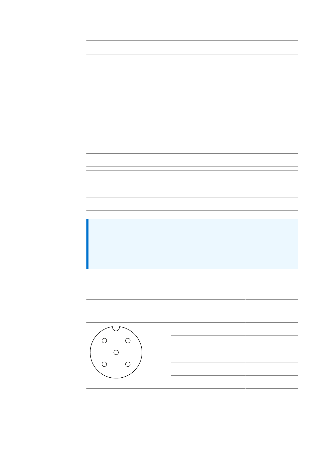
Pin assignment M12 plug connector, female (option C20/D20, C30/D30,
C40/D40)
Plug connector, female A-
coded
Pin RS-232 RS-485
1 RTS GNDI
2 CTS RxB
3 GND RxA
4 TxD TxB
4
3
1
2
5
5 RxD TxA
3. Device description | 3.6 - Option cards | 39
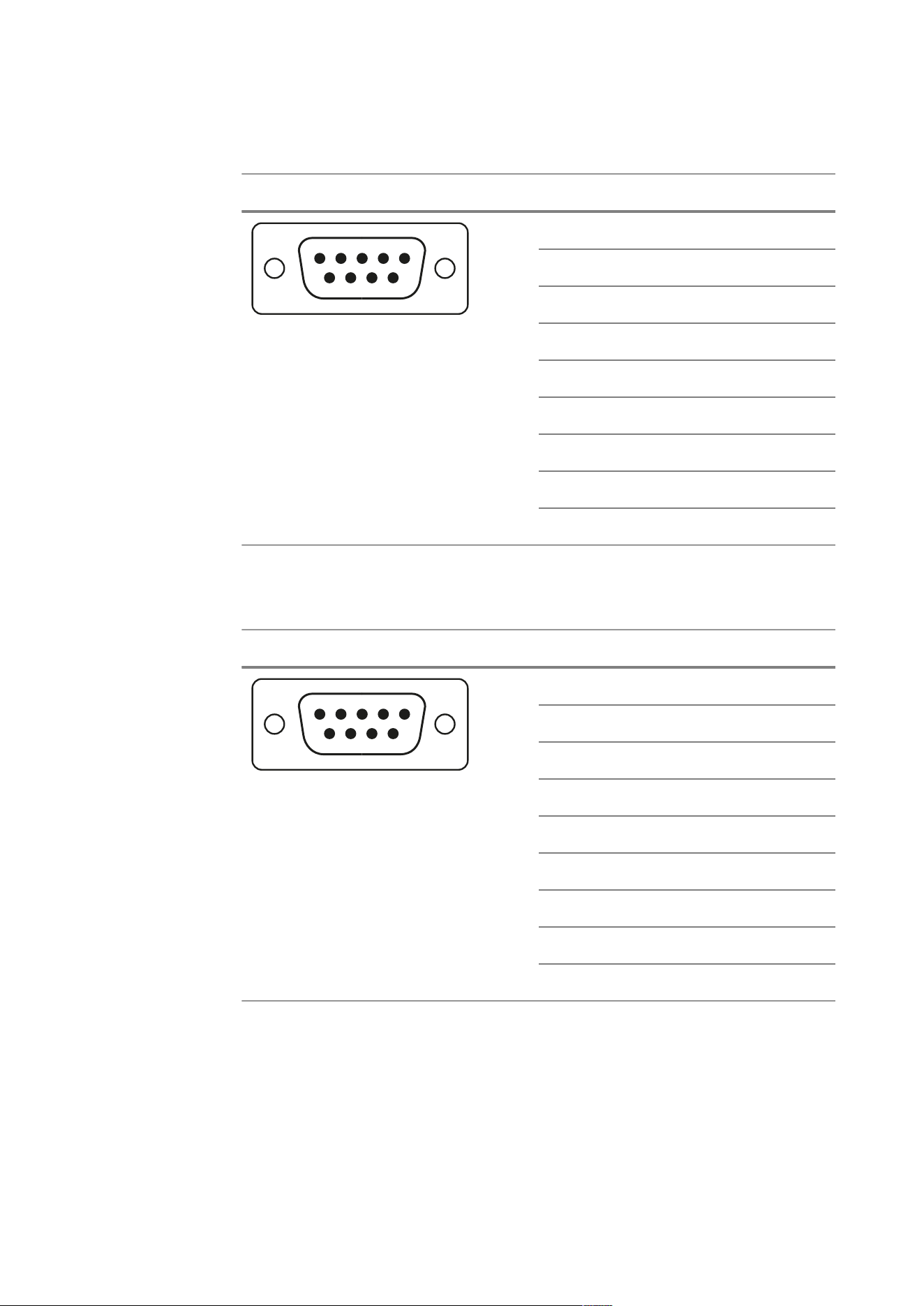
Pin assignment D-sub 9-pin plug connector, female (option C22/D22, C32/
D32, C42/D42)
Plug connection Pin RS-232 RS-485
1 – –
2 TxD TxB
3 RxD TxA
4 – –
5 GND RxA
6 – –
7 CTS RxB
8 RTS GNDI
1
2
3
4
5
6
7
8
9
9 – –
Pin assignment D-sub 9-pin plug connector (option C21/D21, C31/D31,
C41/D41)
Plug connection Pin RS-232 RS-485
1 – –
2 RxD RxB
3 TxD RxA
4 – –
5 GND TxA
6 – –
7 RTS TxB
8 CTS GNDI
1
2
3
4
5
6
7
8
9
9 – –
3. Device description | 3.6 - Option cards | 40
Pin assignment, open cable ends (option C23/D23, C33/D33, C43/D43)
Color Code RS-232 RS-485
Brown bn RTS GNDI
Black bk TxD TxB
Gray gy RxD TxA
White wh CTS RxB
Blue bu GND RxA
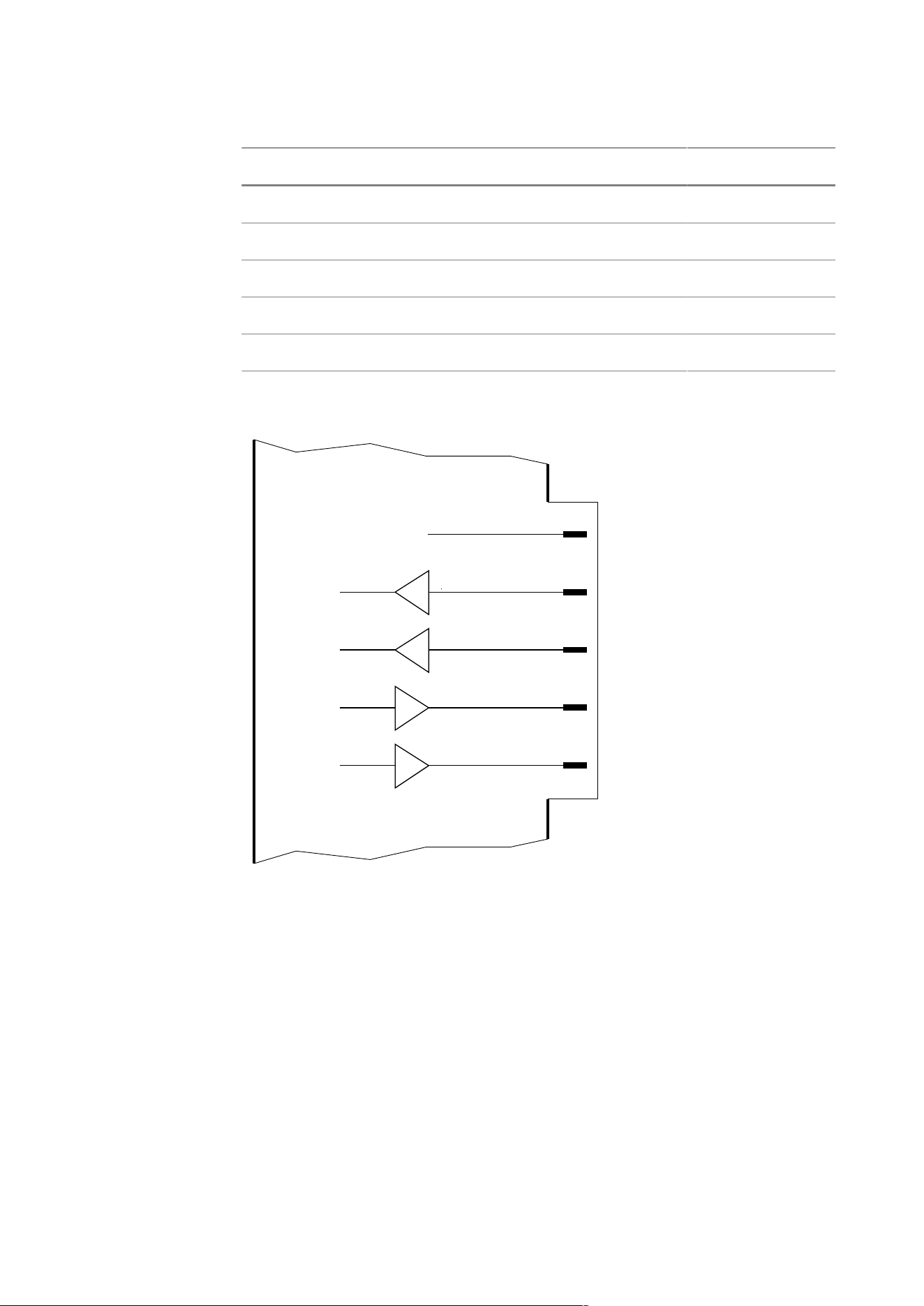
Block diagram RS-232
CTS
Rx
Tx
RTS
7
8
6
5
4
GND
RS-232
3. Device description | 3.6 - Option cards | 41
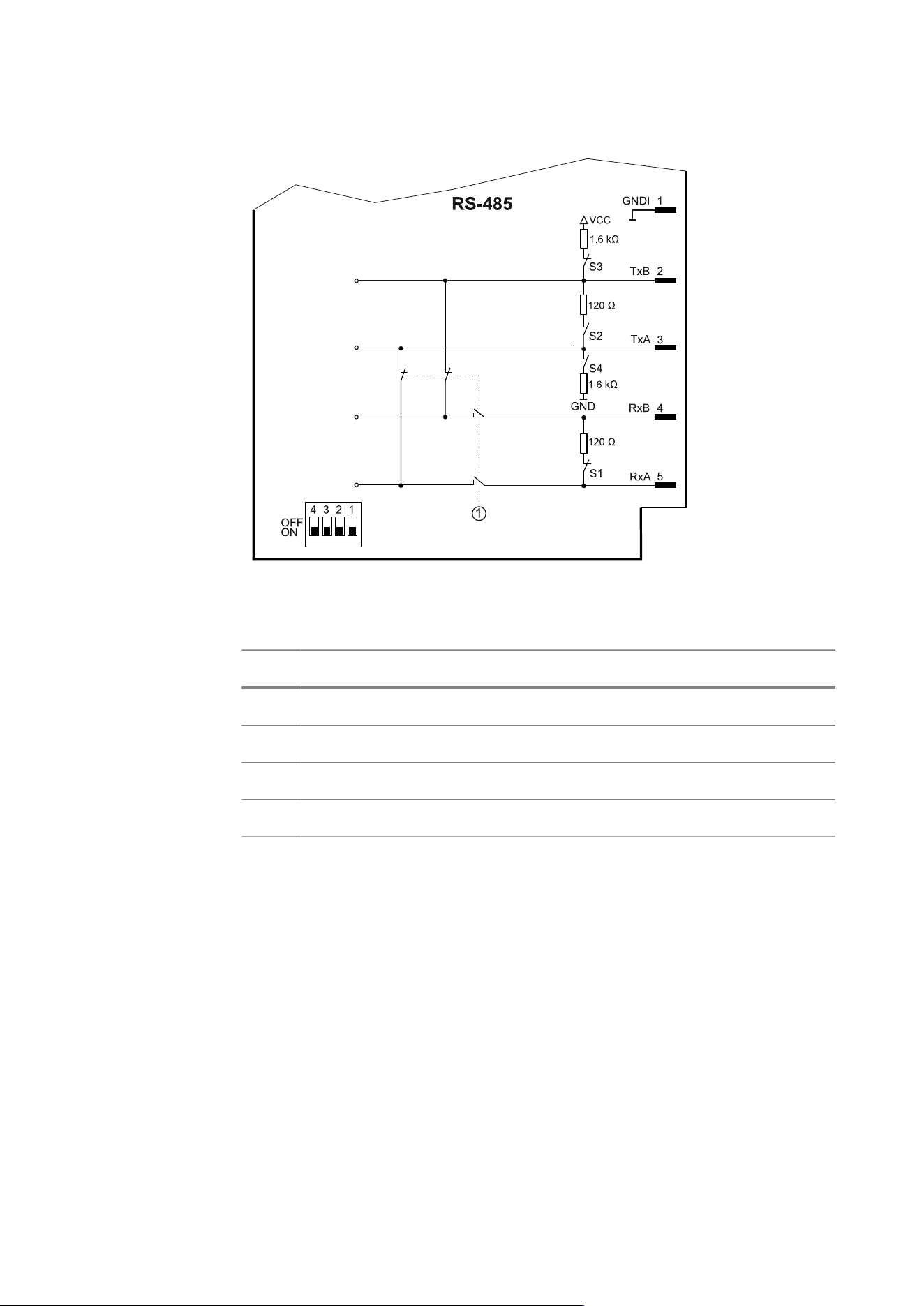
Block diagram RS-485 without terminating resistors (CA2/CA3/CA4)
①2-wire/4-wire switching via software
S Function Settings for RS‑485 switch
1 Rx bus termination (4-wire) OFF (switch up)
2 Tx bus termination OFF (switch up)
3 TxB pull-up resistor OFF (switch up)
4 TxA pull-down resistor OFF (switch up)
3. Device description | 3.6 - Option cards | 42
Block diagram RS-485 with terminating resistors (CB2/CB3/CB4)
①2-wire/4-wire switching via software
S Function Settings for RS‑485 switch
1 Rx bus termination (4-wire) ON (switch down)
2 Tx bus termination ON (switch down)
3 TxB pull-up resistor ON (switch down)
4 TxA pull-down resistor ON (switch down)
3. Device description | 3.6 - Option cards | 43
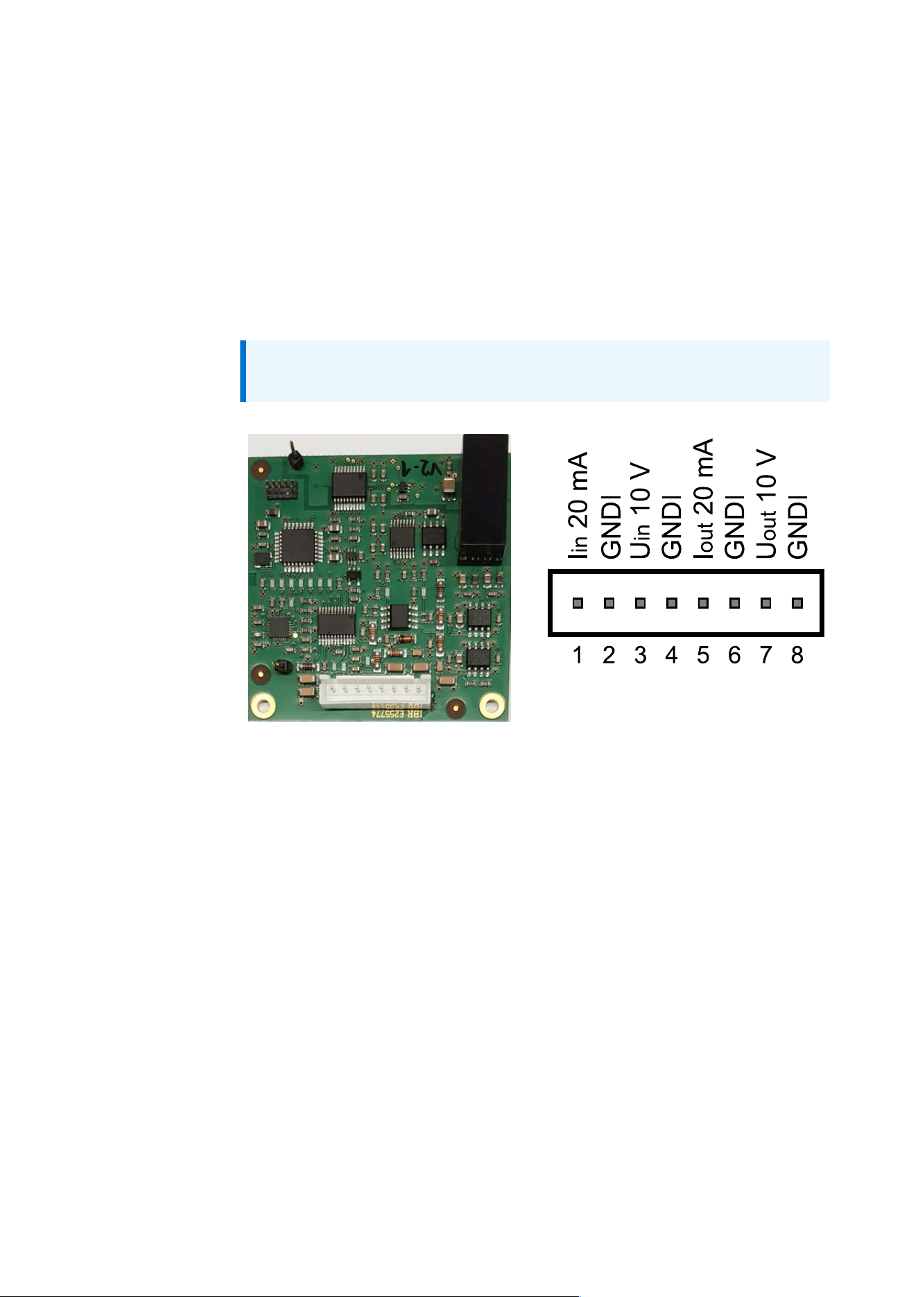
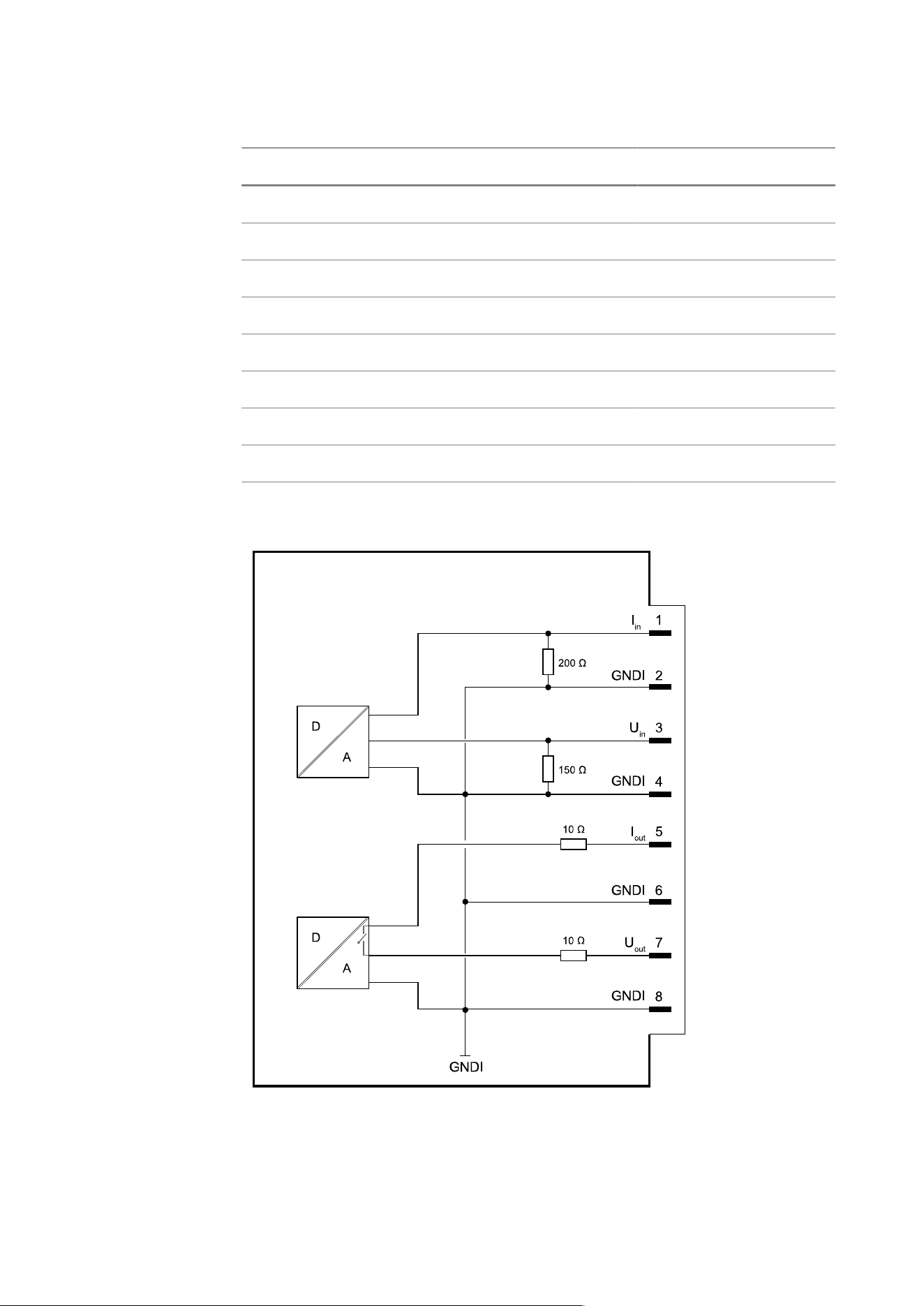
3.6.6 Analog inputs and outputs
The option card has
– 1 analog current input
– 1 analog voltage input
– 1 analog current output or analog voltage output
Both inputs can be used at the same time.
Only one output can be used.
Note: See also, Chapter“Analog inputs and outputs” in the Technical
manual – Firmware

3. Device description | 3.6 - Option cards | 44
Technical data for current and voltage input
Name Data
Type Current input Voltage input
Quantity 1 (I
in
) 1 (V
in
)
Range 0…25 mA 0…12 V
Input impedance 200 Ω 150kΩ
Reference potential GNDI GNDI
Electrical isolation Yes Yes
Resolution 14 bits 14 bits
Offset error: ±0.009% @
20 mA
Offset error: ±0.001%
@ 10 V
Gain error: ±0.300% @ 20
mA
Gain error: ±0.300%
@ 10 V
Max. error
Linearity error: ±0.054%
@ 20 mA
Linearity error:
±0.029% @ 10 V
Max. cable length 150 m 10 m
Technical data for current and voltage output
Name Data
Type Current output Voltage output
Quantity 1 (I
out
) 1 (V
out
)
Range 0…24 mA 0…10 V
Load Max. 500Ω Min. 1kΩ
Reference potential GNDI GNDI
Electrical isolation Yes Yes
Resolution 16 bits 16 bits

3. Device description | 3.6 - Option cards | 45
Name Data
Type Current output Voltage output
Offset error: ±0.008% @
20 mA
Offset error: ±0.005%
@ 10 V
Gain error: ±0.720% @ 20
mA
Gain error: ±0.081%
@ 10 V
Max. error
Linearity error: ±0.030%
@ 20 mA
Linearity error:
±0.020% @ 10 V
Max. cable length 150 m 10 m
Cable(s) See accessory documentation
Connections
Name Data
Connection
Position 2
M12 plug connector, female (E20)
M16 cable gland:
– Open cable ends (E21)
Screen connection in the cable gland
Connection
Position 3
M12 plug connector, female (E30)
M16 cable gland:
– Open cable ends (E31)
Screen connection in the cable gland
Connection
Position 4
M12 plug connector, female (E40)
M16 cable gland:
– Open cable ends (E41)
Screen connection in the cable gland
3. Device description | 3.6 - Option cards | 46
Absolute maximum ratings
Name Data
Current input Voltage: -0.5V…+15.5V
Current: 30 mA
Voltage input Voltage: -0.5V…+15.5V
Current: 80 µA
Current output Max. load: 6000 Ω
Note:
Loads that exceed the values specified under “absolute maximum
ratings,” can cause permanent damage to the device. The function and
reliability of the device cannot be guaranteed if it is used under different
conditions than those specified under “Technical data.”
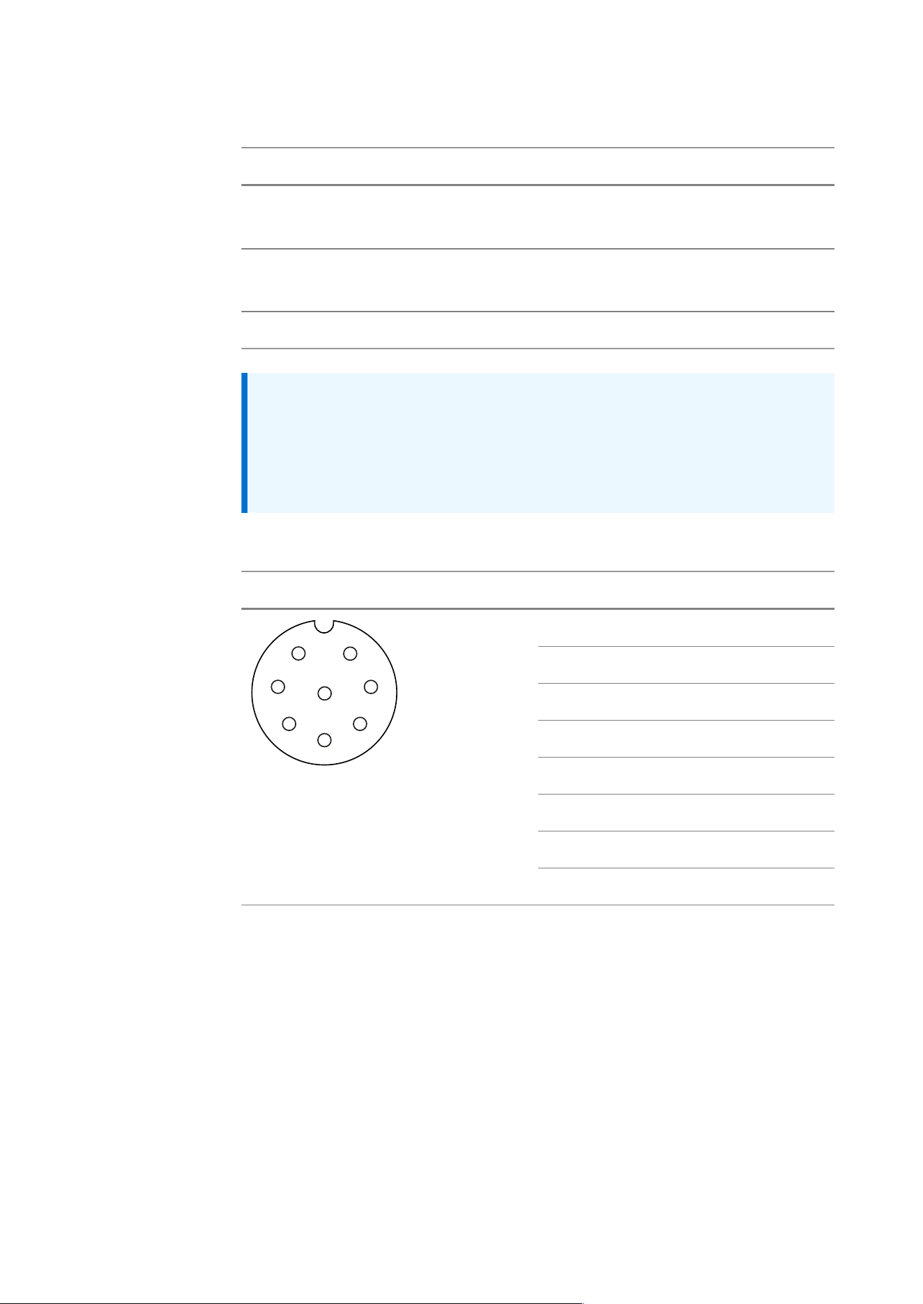
Pin assignment M12 plug connector, female (option E20, E30, E40)
Plug connector, female A-coded Pin Signal
1 I
in
(current 20 mA)
2 GNDI
3 V
in
(voltage 10 V)
4 GNDI
5 I
out
(current 20 mA)
6 GNDI
7 V
out
(voltage 10 V)
7
8
1
2
3
6
5
4
8 GNDI
3. Device description | 3.6 - Option cards | 47
Pin assignment, open cable ends (option E21, E31, E41)
Color Code Signal
White wh I
in
(current 20 mA)
Brown bn GNDI
Green gn V
in
(voltage 10 V)
Yellow ye GNDI
Gray gy I
out
(current 20 mA)
Pink pk GNDI
Blue bu V
out
(voltage 10 V)
Red rd GNDI
Block diagram

3. Device description | 3.6 - Option cards | 48
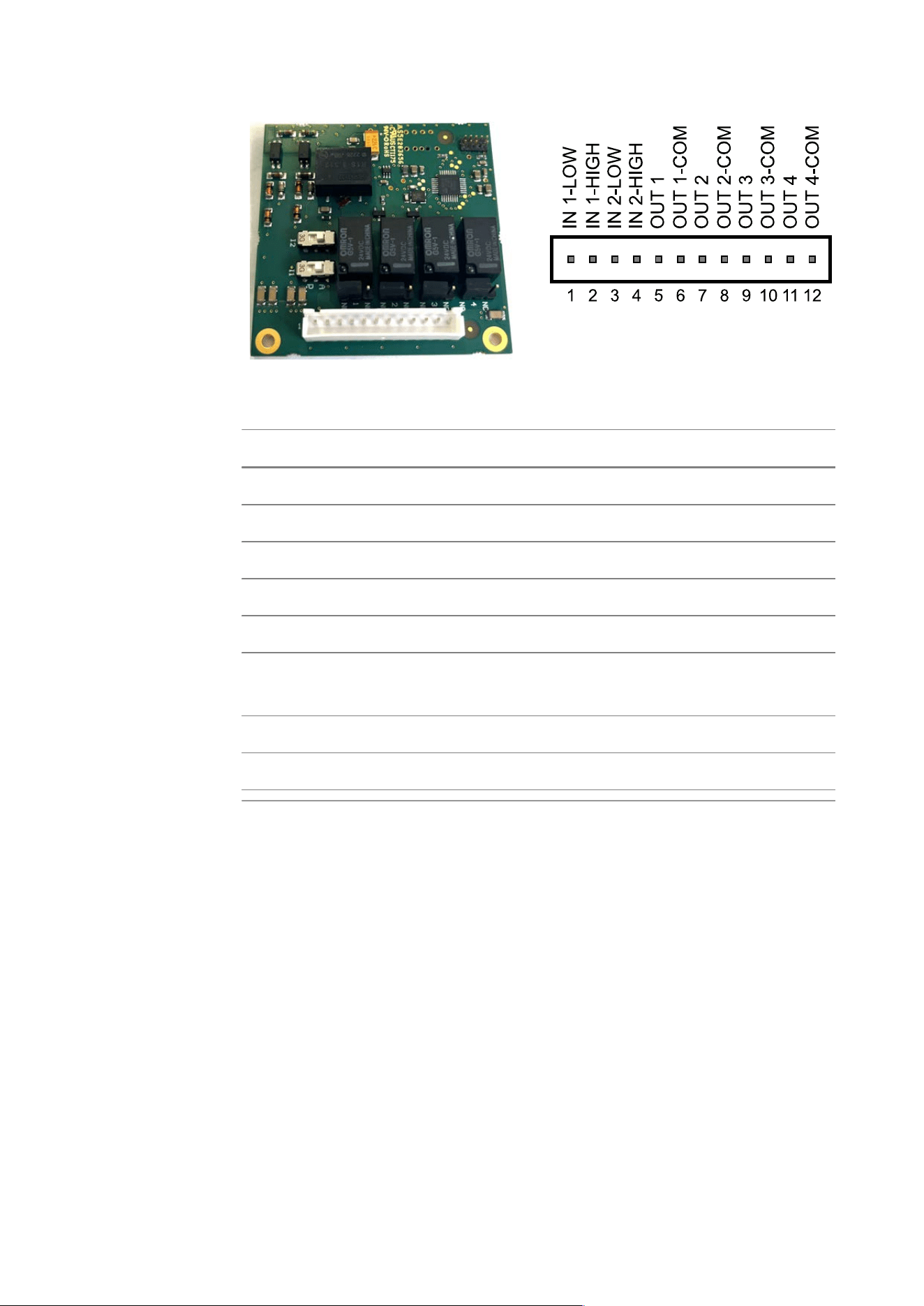
3.6.7 Digital inputs and outputs (2 IN/4 OUT)
On the option card, there are two opto-decoupled inputs (IN1, IN2) and 4
passive outputs decoupled by relays (OUT1, OUT2, OUT3, OUT4).
The two opto-decoupled inputs are active for the following options:
– FA2/FC2
– FA3/FC3
The two opto-decoupled inputs are passive for the following options:
– FB2/FD2
– FB3/FD3
The 4 relay outputs are NO for the following options:
– FA2/FB2
– FA3/FB3
The 4 relay outputs are NC for the following options:
– FC2/FD2
– FC3/FD3
Note:
The following can only be carried out by trained specialists:
– The respective input can be set to active or passive via two switches.
– The respective output can be set to “normally closed” or “normally
open” via four jumpers.
The option card needs to be removed to change the switch/jumper
setting.
Note:
See also, Chapter“Digital inputs and outputs” in the Technical manual –
Firmware
3. Device description | 3.6 - Option cards | 49
Technical data
Name Data
Inputs, active (A)
Quantity 2 (IN1-LOW, IN1-HIGH; IN2-LOW, IN2-HIGH)
Configuration active
Current Max. 3mA
Voltage 12 V
Logic level LOW: open
HIGH: closed
Reference potential GNDI
Electrical isolation Yes, via optocoupler

3. Device description | 3.6 - Option cards | 50
Name Data
Inputs, passive (P)
Quantity 2 (IN1-LOW, IN1-HIGH; IN2-LOW, IN2-HIGH)
Configuration passive
Current Max. 7 mA @ 24 V
Max. 3 mA @ 12 V
Voltage 10…28 V
Logic level LOW: 0…5 V
HIGH: 10…28 V
Reference potential IN1-LOW, IN2-LOW
Electrical isolation Yes, via optocoupler
Outputs
Quantity 4 (OUT 1, OUT 2, OUT 3, OUT 4)
Configuration Passive, NO or NC
Voltage U
DC
=30V/U
AC
=30V
Current 0.5 A
Reference potential OUT1-COM, OUT2-COM, OUT3-COM, OUT4-
COM
Electrical isolation Yes, via relay
Connections
Connection
Position 2
M12 plug connector, female (F20)
M16 cable gland:
– Open cable ends (F21)
Screen connection in the cable gland
Connection
Position 3
M12 plug connector, female (F30)
M16 cable gland:
– Open cable ends (F31)
Screen connection in the cable gland
Connection
Position 4
M12 plug connector, female (F40)

3. Device description | 3.6 - Option cards | 51
Name Data
M16 cable gland:
– Open cable ends (F41)
Screen connection in the cable gland
Max. cable length 50 m
Cable(s) See accessory documentation
Absolute maximum ratings
Inputs Current: 50 mA
Voltage: 30 V
Outputs Current: 1 A
Voltage: U
DC
=60V, U
AC
=125V
Switching processes: min. 100,000, max. 1800/
hour
Note:
Loads that exceed the values specified under “absolute maximum
ratings,” can cause permanent damage to the device. The function and
reliability of the device cannot be guaranteed if it is used under different
conditions than those specified under “Technical data.”

3. Device description | 3.6 - Option cards | 52
Pin assignment M12 plug connector, female (option F20, F30, F40)
Plug connector, female A-coded Pin Signal
1 IN1-LOW
2 IN1-HIGH
3 IN2-LOW
4 IN2-HIGH
5 OUT1
6 OUT1-COM
7 OUT2
8 OUT2-COM
9 OUT3
10 OUT3-COM
11 OUT4
8
10
1
2
3
7
6
4
9
5
12
11
12 OUT4-COM
Pin assignment, open cable ends (option F21, F31, F41)
Color Code Signal
Brown bn IN1-LOW
Blue bu IN1-HIGH
White wh IN2-LOW
Green gn IN2-HIGH
Pink pk OUT1
Yellow ye OUT1-COM
Black bk OUT2
Gray gy OUT2-COM
Red rd OUT3
Yellow-violet ye-vt OUT3-COM
Grey-pink gy-pk OUT4
Pink-blue pk-bu OUT4-COM
3. Device description | 3.6 - Option cards | 53
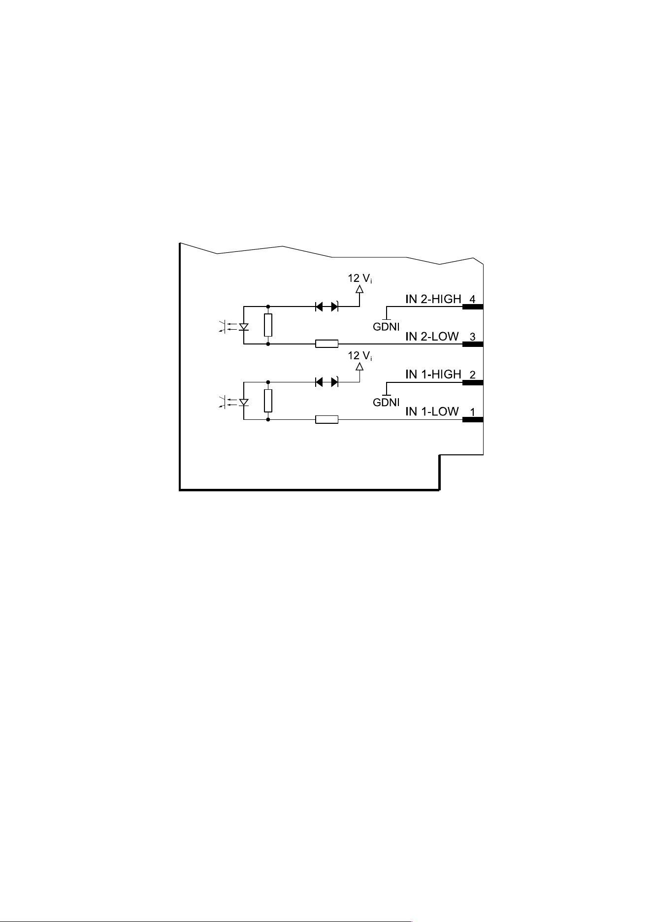
3.6.7.1 Digital inputs (2 IN)
Block diagram for active inputs
Option:
– FA2/FC2
– FA3/FC3
– FA4/FC4
3. Device description | 3.6 - Option cards | 54
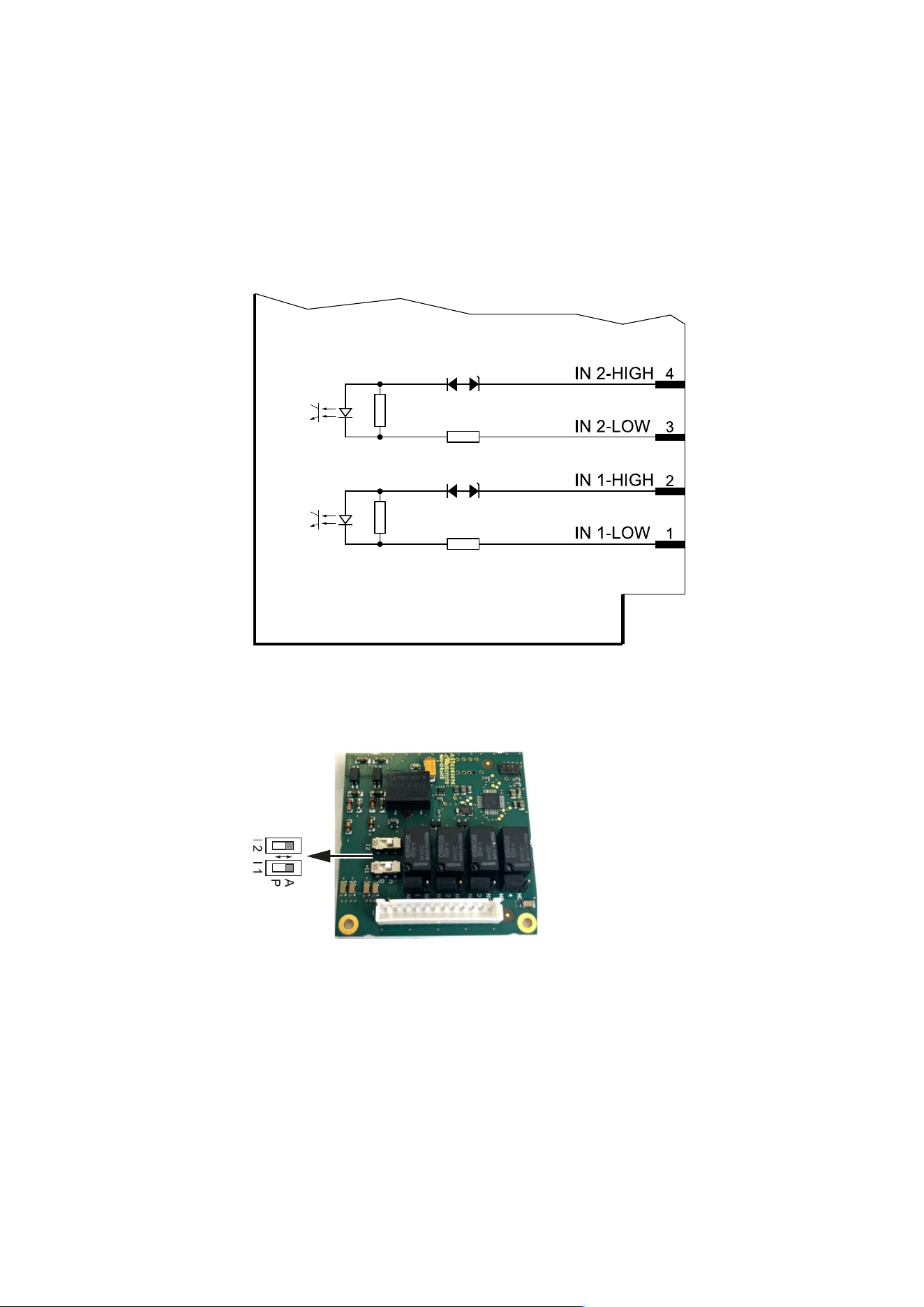
Block diagram for passive inputs
Option:
– FB2/FD2
– FB3/FD3
– FB4/FD4
There is one switch (I 1, I 2) for each of the 2 inputs (IN 1, IN 2).
Each channel can be switched ac
tively (A) or passively (P) indepen
dently of one another.
The delivery condition depends on
the option.
3. Device description | 3.6 - Option cards | 55
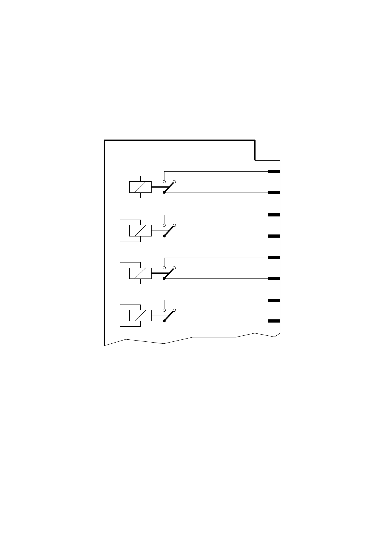
3.6.7.2 Digital outputs (4 relays OUT)
Block diagram for outputs as normally open (NO) contacts
Option:
– FA2/FB2
– FA3/FB3
– FA4/FB4
OUT 4-COM
OUT 4
OUT 3-COM
OUT 3
OUT 2-COM
12
11
10
9
8
OUT 2
7
OUT 1-COM
OUT 1
6
5
3. Device description | 3.6 - Option cards | 56
Block diagram for outputs as normally closed (NC) contacts
Option:
– FC2/FD2
– FC3/FD3
– FC4/FD4
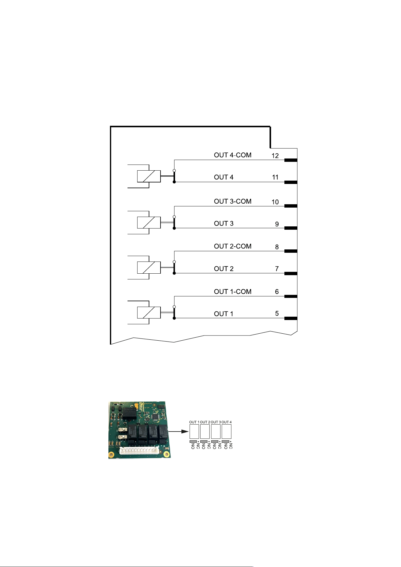
There is a jumper for each of the four relay outputs (OUT 1, OUT 2, OUT 3,
OUT 4).
NO: normally open
NC: normally closed
The delivery condition depends on
the option.
3. Device description | 3.6 - Option cards | 57
3.6.8 Digital inputs and outputs (4 IN/6 OUT)
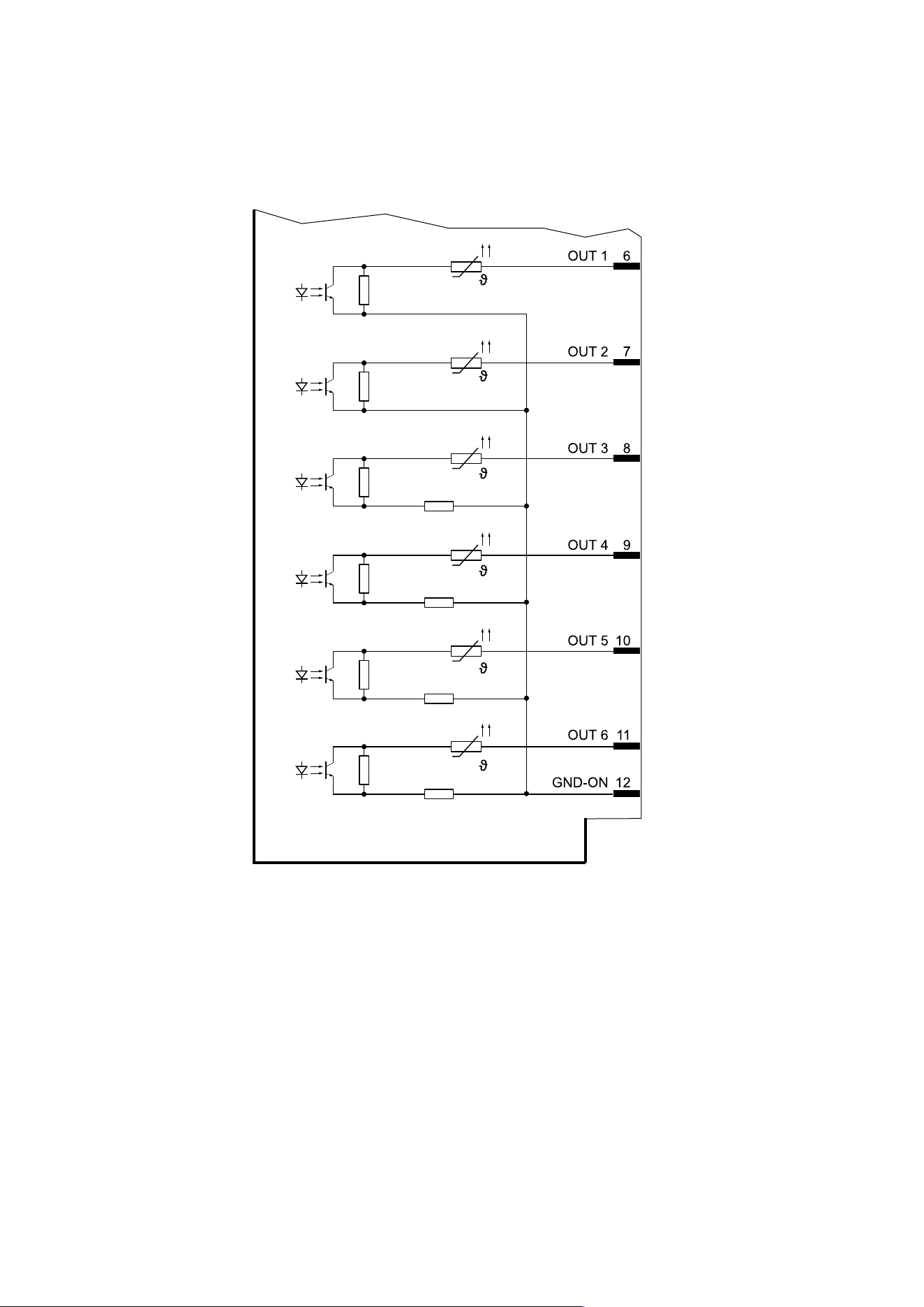
The option card has 4 passive opto-decoupled inputs and 6 passive opto-
decoupled outputs.
Note: See also, Chapter“Digital inputs and outputs” in the Technical
manual – Firmware

3. Device description | 3.6 - Option cards | 58
Technical data
Name Data
Inputs
Quantity 4 (IN 1, IN 2, IN 3, IN 4)
Configuration Passive
Current Max. 7 mA @ 24 V
Max. 3 mA @ 12 V
Voltage 10…28 V
Logic level LOW: 0…5 V
HIGH: 10…28 V
Reference potential GND-IN (signal GNDI)
Electrical isolation Yes, via optocoupler
Outputs
Quantity 6 (OUT 1, OUT 2, OUT 3, OUT 4, OUT 5, OUT 6)
Configuration Passive
Current 30 mA
Voltage 24 V
Reference potential GND-OUT (signal GNDO)
Electrical isolation Yes, via optocoupler
Connections
Connection
Position 2
M12 plug connector, female (G20)
M16 cable gland:
– Open cable ends (G21)
Screen connection in the cable gland
Connection
Position 3
M12 plug connector, female (G30)
M16 cable gland:
– Open cable ends (G31)
Screen connection in the cable gland

3. Device description | 3.6 - Option cards | 59
Name Data
Connection
Position 4
M12 plug connector, female (G40)
M16 cable gland:
– Open cable ends (G41)
Screen connection in the cable gland
Max. cable length 50 m
Cable(s) See accessory documentation
Absolute maximum ratings
Inputs Current: 50 mA
Voltage: 30 V
Outputs Current: 70 mA
Voltage: 30 V
Note:
Loads that exceed the values specified under “absolute maximum
ratings,” can cause permanent damage to the device. The function and
reliability of the device cannot be guaranteed if it is used under different
conditions than those specified under “Technical data.”

3. Device description | 3.6 - Option cards | 60
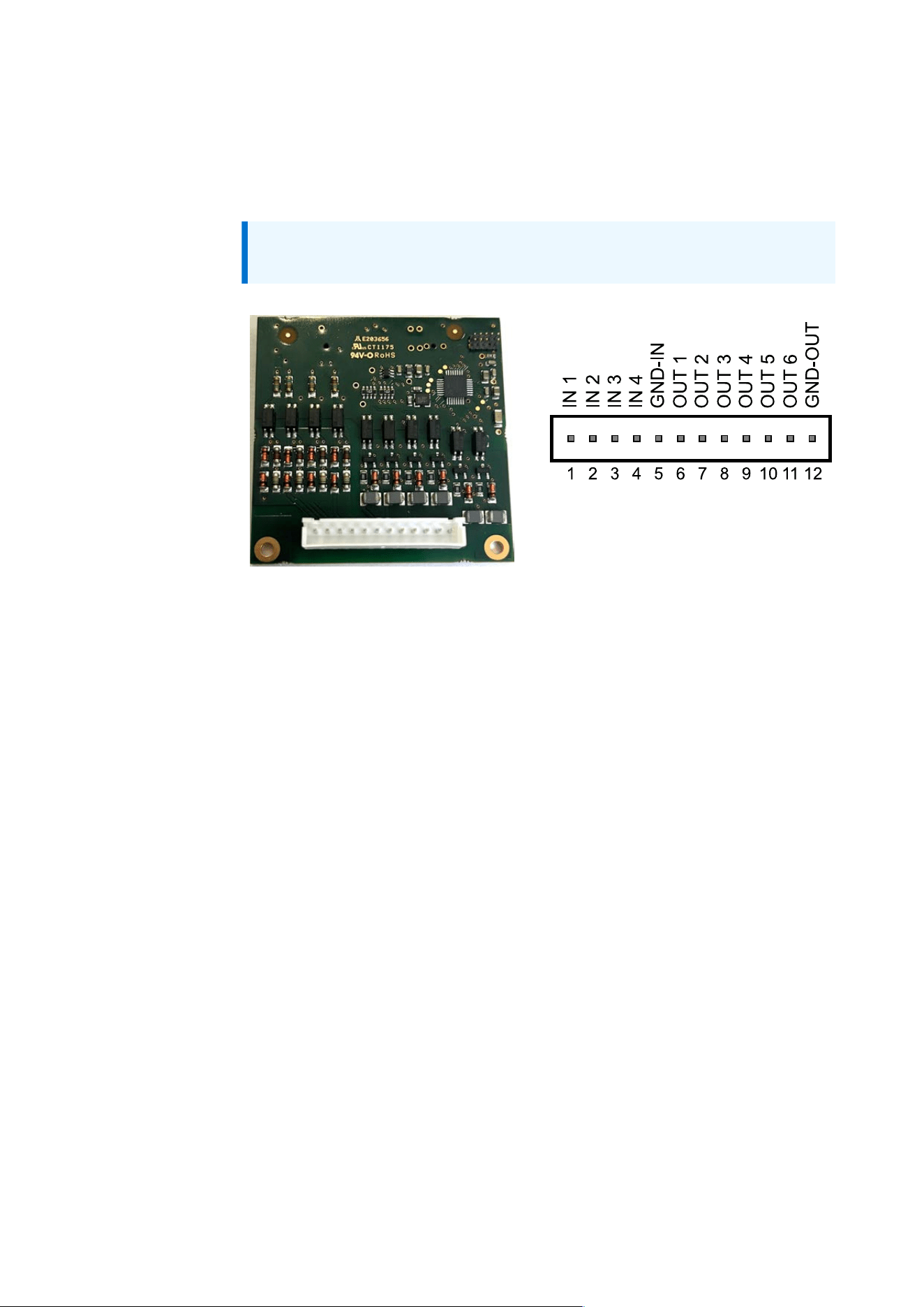
Pin assignment M12 plug connector, female (option G20, G30, G40)
Plug connector, female A-coded Pin Signal
1 IN1
2 IN2
3 IN3
4 IN4
5 GND-IN
6 OUT1
7 OUT2
8 OUT3
9 OUT4
10 OUT5
11 OUT6
8
10
1
2
3
7
6
4
9
5
12
11
12 GND-OUT
Pin assignment, open cable ends (option G21, G31, G41)
Color Code Signal
Brown bn IN1
Blue bu IN2
White wh IN3
Green gn IN4
Pink pk GND-IN
Yellow ye OUT1
Black bk OUT2
Gray gy OUT3
Red rd OUT4
Yellow-violet ye-vt OUT5
Grey-pink gy-pk OUT6
Pink-blue pk-bu GND-OUT
3. Device description | 3.6 - Option cards | 61
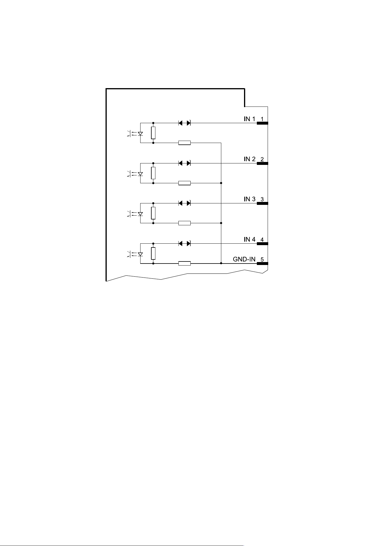
3.6.8.1 Digital inputs (4 IN)
Block diagram for digital inputs
3. Device description | 3.6 - Option cards | 62
3.6.8.2 Digital outputs (6 optocoupler OUT)
Block diagram for digital outputs
3. Device description | 3.6 - Option cards | 63
3.6.9 Fieldbus modules
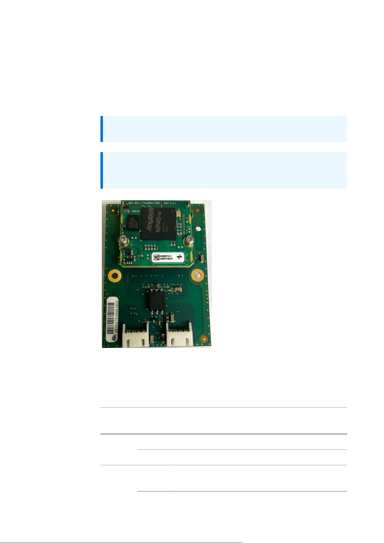
3.6.9.1 ProfiBus DP interface
Communication protocol and syntax comply with the ProfiBus DP bus
standard according to IEC 61158.
Note:
See also Chapter “Fieldbus settings” in the Technical manual – Firmware.
Note:
The configuration file can be downloaded at https://controller-
software.minebea-intec.com/.
The communication interface “Anybus® CompactCom™40 Brick
PROFIBUS” (item number AB6670) from HMS is integrated into the fieldbus
module. Technical data can be found on the HMS website.
Connection data
Option Connec
tion
Data
Position 7 M12 plug connectorHDP01
Position 8 M12 plug connector, female
HDP02 Position 7 M16 cable gland including cable to M12 plug connec
tor

3. Device description | 3.6 - Option cards | 64
Option Connec
tion
Data
Position 8 M16 cable gland including cable to M12 plug connec
tor, female
Pin assignment M12 plug connector, female and plug connector (option
HDP01, HDP02)
B-coded Pin Signal to plug con
nector, female
Signal to plug con
nector
1 ISO 5V –
2 PB A PB A
3 ISO GND –
4 PB B PB B
4
3
1
2
5
5 – –
3. Device description | 3.6 - Option cards | 65
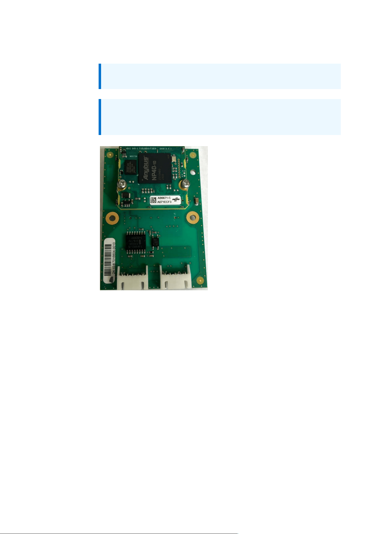
3.6.9.2 DeviceNet interface
Note:
See also Chapter “Fieldbus settings” in the Technical manual – Firmware.
Note:
The configuration file can be downloaded at https://controller-
software.minebea-intec.com/.
The communication interface “Anybus® CompactCom™40 Brick
DeviceNet” (item number AB6671) from HMS is integrated into the fieldbus
module. Technical data can be found on the HMS website.

3. Device description | 3.6 - Option cards | 66
Connection data
Option Connec
tion
Data
Position 7 M12 plug connectorHDN01
Position 8 M12 plug connector, female
Position 7 M16 cable gland including cable to M12 plug connec
tor
HDN02
Position 8 M16 cable gland including cable to M12 plug connec
tor, female
Pin assignment M12 plug connector, female and plug connector (option
HDN01, HDN02)
A-coded Pin Signal to plug con
nector, female
Signal to plug con
nector
1 Screen Screen
2 V+ V+
3 V- V-
4 CAN_H CAN_H
4
3
1
2
5
5 CAN_L CAN_L
3. Device description | 3.6 - Option cards | 67
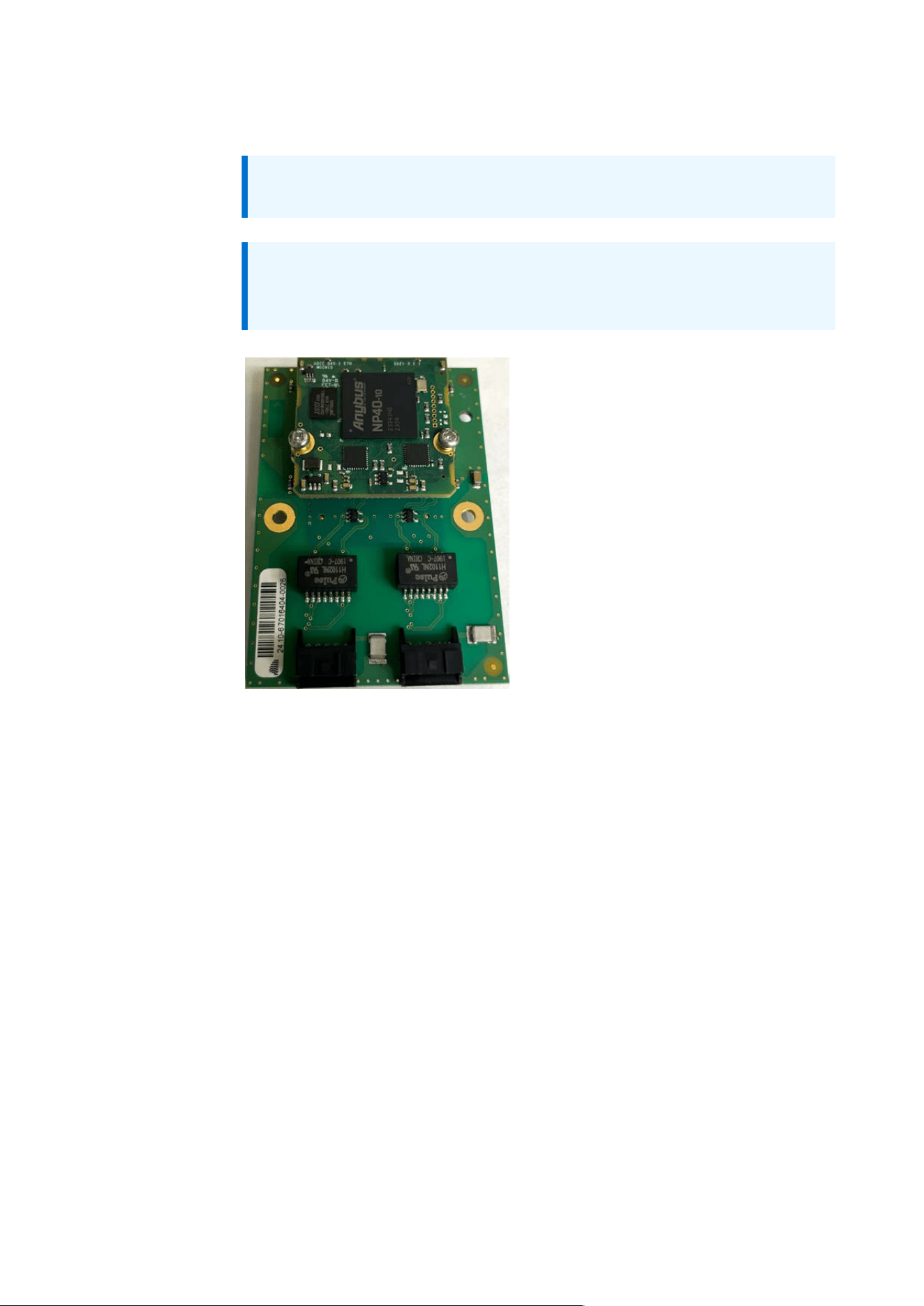
3.6.9.3 ProfiNet interface
Note:
See also Chapter “Fieldbus settings” in the Technical manual – Firmware.
Note:
The configuration file can be downloaded at https://controller-
software.minebea-intec.com/.
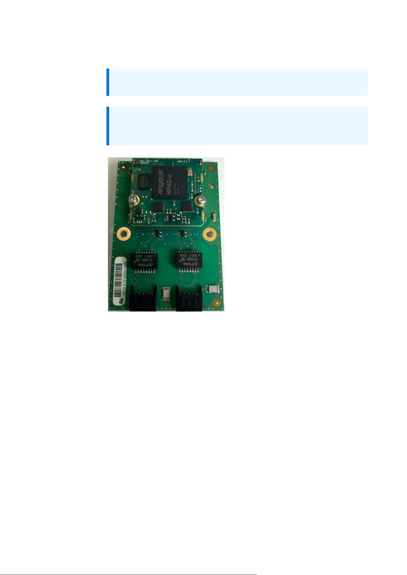
The communication interface “Anybus® CompactCom™40 Brick PROFINET
IRT” (item number AB6675) from HMS is integrated into the fieldbus module.
Technical data can be found on the HMS website.

3. Device description | 3.6 - Option cards | 68
Connection data
Option Connec
tion
Data
Position 7 M12 plug connector, femaleHPN01
Position 8 M12 plug connector, female
Position 7 M16 cable gland including cable to RJ45 plug connec
tor
HPN02
Position 8 M16 cable gland including cable to RJ45 plug connec
tor
Pin assignment M12 plug connector, female (option HPN01)
D-coded Pin Signal
1 TD+
2 RD+
3 TD-
4
3
1
2
4 RD-
3. Device description | 3.6 - Option cards | 69
3.6.9.4 EtherNet/IP interface
Note:
See also Chapter “Fieldbus settings” in the Technical manual – Firmware.
Note:
The configuration file can be downloaded at https://controller-
software.minebea-intec.com/.
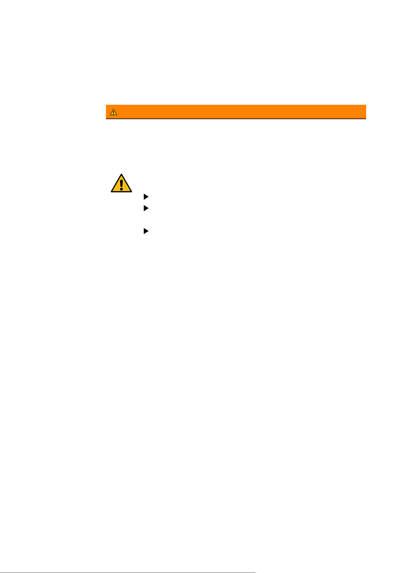
The communication interface “Anybus® CompactCom™40 Brick EtherNet/
IP” (item number AB6674) from HMS is integrated into the fieldbus module.
Technical data can be found on the HMS website.

3. Device description | 3.6 - Option cards | 70
Connection data
Option Connec
tion
Data
Position 7 M12 plug connector, femaleHIP01
Position 8 M12 plug connector, female
Position 7 M16 cable gland including cable to RJ45 plug connec
tor
HIP02
Position 8 M16 cable gland including cable to RJ45 plug connec
tor
Pin assignment M12 plug connector, female (option HIP01)
D-coded Pin Signal
1 TD+
2 RD+
3 TD-
4
3
1
2
4 RD-
4. Device installation | 71
4 Device installation
4.1 Opening/closing the device
WARNING
Performing electrical work on a device that is connected and/or
switched on can have life-threatening consequences.
When removing covers or parts using tools, live parts may be
exposed. Please note that capacitors in the device may still be
charged even after disconnecting the device from all voltage
sources.
The device must not be opened by the operating personnel.
The device must only be opened by trained specialists
according to specifications.
Disconnect the device from the power supply and wait at least
10s (the LED must have gone out) before opening.
4. Device installation | 4.1 - Opening/closing the device | 72
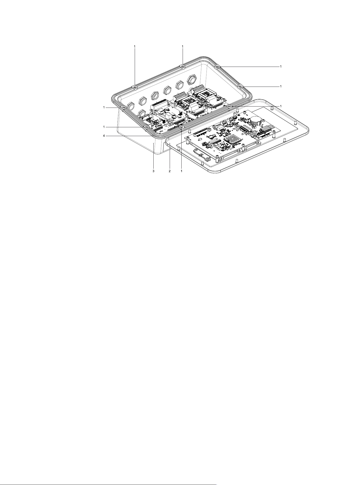
1. Loosen the 8 M4 cap nuts(1) using a 7mm socket wrench, carefully
remove the cover (4) and set aside.
Notice: The connections cables must not be disconnected.
The seal (4) remains in the cover (2).
2. After completing work, place the cover(2) carefully onto the lower
part(3).
The seal(4) must not be crushed. The drill holes in the seal must be
aligned with the drill holes in the lower part (3).
3. Tighten the 8 M4 cap nuts(1) with a torque of 1.5Nm.
4. Device installation | 4.2 - Connecting the functional ground | 73
4.2 Connecting the functional ground
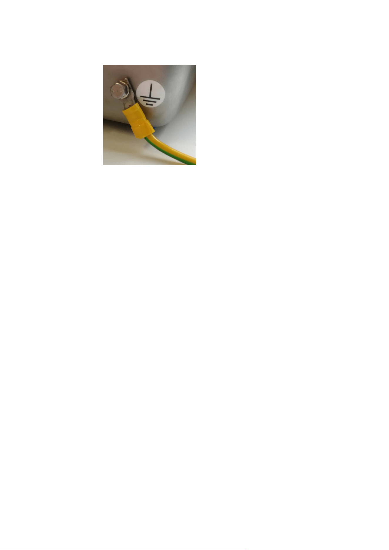
The functional ground must be connected as shown , see position G in
Overview of connections.
4.3 Establishing connections for option cards
The connections for the installed option cards can be found in the
descriptions under Option cards.
4.4 Switching on the device
– Connect the device to a power supply.
– The device switches on.
– For further steps, see the Technical manual – Firmware.
5. Cleaning | 74
5 Cleaning
5.1 Instructions for cleaning
The device must be cleaned of contaminants on a regular basis.
WARNING
Performing work on a device that is switched on can have life-
threatening consequences.
Disconnect the device from the power supply before cleaning
(disconnect the power plug from the electrical outlet).
Do not open the device for cleaning.
NOTICE
Property damage caused by the use of unsuitable cleaning utensils/
products.
Damage to the device.
Prevent moisture from penetrating the interior.
Do not use aggressive cleaning agents (solvents or similar agents), see
Cleaning agents.
For use in the food industry, use a cleaning agent suitable for that
particular working environment.
Use soft sponges, brushes, and cloths.
Spraying with water or blowing off with compressed air is not permissible.
1. Unplug device from mains supply, disconnect any data cables.
2. Clean the device, referring to the information provided by the
manufacturer.
3. Wipe down the device with a soft, dry cloth after cleaning.

5. Cleaning | 5.2 - Cleaning agents | 75
5.2 Cleaning agents
NOTICE
Some cleaning agents may not be compatible with the product material.
Only use disinfectants and cleaning agents in line with the manufacturer’s
instructions.
Do not use any abrasive sponges containing iron, steel brushes, or
cleaning sponges made of steel wool.
Always test cleaning agents and materials in non-critical areas first before
using them.

6. Disposal | 76
6 Disposal
Our products and their packaging must not be disposed of in municipal
waste (e.g., garbage can for recyclable packaging, garbage can for paper
packaging, etc.). They can either be recycled by the customer themselves,
providing this complies with requirements set out by electrical or electronic
waste or packaging waste laws, or sent back to MinebeaIntec at a charge.
This option of returning the product is intended to provide proper recycling
or reuse in a manner that is collected separately from municipal waste.
Before disposing of or scrapping the old products, any single-use or
rechargeable batteries should be removed and taken to a suitable collection
point. The type of battery used is specified in the technical data.
Please see our General Terms and Conditions for further information.
Service addresses for repair acceptance and collection points can be found in
the product information enclosed with the product as well as on our website
(www.minebea-intec.com).
Minebea Intec Bovenden GmbH & Co. KG
Leinetal 2
37120 Bovenden
WEEE Reg. no. DE58091735
Should you have any further questions, please contact your local service rep
resentative or our service center.
Minebea Intec Bovenden GmbH & Co. KG
Repair center
Leinetal 2
37120 Bovenden, Germany
Phone: +49.551.30983.333
We reserve the right not to accept products that are contaminated with haz
ardous substances (ABC contamination).

7. Specification | 77
7 Specification
7.1 General technical data
The following characteristics are valid after a warm-up time of at least 2
hours (reference temperature: 23°C).
7.1.1 display
Type Size Display
TFT color display 5.0" 800 x 480 pixels
7.1.2 Supply voltage version 100–240VAC
U
AC
=100…240V +10%/-15%;
50/60Hz
30 VA
T1AL 250VAC 3×10.1mm
7.1.3 Supply voltage version 24 V DC
Supply voltage U
DC
=24 V SELV/PELV
Energy/power limitation
±10%
Max. power consumption 20 W
Primary fuse T2AL 125UDC; 3×10.1mm
Connection conditions Only for low-voltage DC
power supply networks
without transient over
voltages on secondary
circuits

7. Specification | 7.1 - General technical data | 78
7.1.4 Buffering of the date/time module
The lithium battery for buffering of the date/time module is already activated
upon delivery and is not intended to be replaced by the customer.
Device continuously connected to
mains voltage
up to 10 yearsService life
Device not connected to mains
voltage for some time (e.g., in
storage)
up to 7 years
7.1.5 Backup batteries (for outages)
Type NIMH AAA
Max. 1.2V; 600 mAh
Model GP60AAAHT3
Quantity 3 pcs
Manufacturer GP
Note:
See also Chapter “Operating & display” in the Technical manual –
Firmware.
7.1.6 NFC
Data from NFC tags can be read by NFC if this is supported by the device
configuration. This function can be used for user identification (see Chapter
“Add/edit user” in the Technical manual – Firmware) or on an application-
specific basis.
The antenna is positioned on the back of the front membrane (see Device
front).
7. Specification | 7.2 - Housing | 79
7.2 Housing
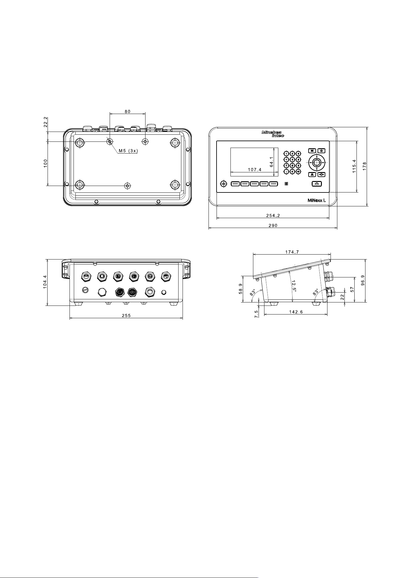
7.2.1 Housing dimensions
All dimensions in mm

7. Specification | 7.2 - Housing | 80
7.2.2 Materials
Component Material
Housing 1.4301/AISI 304
Gasket EPDM
Membrane keyboard PET
Rubber feet EPDM
7.2.3 IP protection
– The device only has IP67, IP69 and NEMA 4X indoor protection with a rub
ber seal installed and secure connection (fastened plugs + cable gland or
M12 plug connector and connected cable).
– The installation of devices with fastened plugs/cable glands must be car
ried out and checked by trained electricians.
7. Specification | 7.3 - Ambient conditions | 81
7.3 Ambient conditions
The ambient conditions only apply for indoor use.
Temperature range
Ambient temperature for oper
ation*
-10…+40°C
Power-on temperature > 0°C
Ambient temperature for stor
age/transport
-20…+60°C
Humidity * < 95%, no condensation (in accordance
with IEC 60068-2) at 40°C
Protection grade IP69; IP69K and NEMA4X indoor
Operating altitude <2000m above sea level (according to
EN 61010)
Vibrations The device must not be exposed to
strong vibrations.
Degree of contamination 2
Note: *
The indicator can be operated in a humid environment.
A combination of very high humidity and very high temperature at the
installation location of the indicator should be avoided.
Always avoid aggressive chemical vapors.
7.4 Electromagnetic Compatibility (EMC)
All data in compliance with EN IEC 61326 industrial section.

8. Appendix | 82
8 Appendix
8.1 Certificates
Ser. no. Name Document no.
1 EU Declaration of Conformity
8.2 Legal Information on conformity
8.2.1 FCC Statement
This equipment has been tested and found to comply with the limits for a
Class A digital device, pursuant to part 15 of the FCC Rules. These limits are
designed to provide reasonable protection against harmful interference
when the equipment is operated in a commercial environment. This equip
ment generates, uses, and can radiate radio frequency energy and, if not in
stalled and used in accordance with the instruction manual, may cause harm
ful interference to radio communications. Operation of this equipment in a
residential area is likely to cause harmful interference in which case the user
will be required to correct the interference at his own expense.
8.2.2 IC Statement
This device complies with Industry Canada license-exempt RSS standard(s).
Operation is subject to the following two conditions:
1. this device may not cause interference, and (2) this device must accept
any interference, including interference that may cause undesired opera
tion of the device.
2. this device must accept any interference, including interference that may
cause undesired operation of the device.
Le present appareil est conforme aux CNR d'Industrie Canada applicables
aux appareils radio exempts de licence.
L'exploitation est autorisee aux deux conditions suivantes :
1. l'appareil ne doit pas produire de brouillage, et
2. l'utilisateur de l'appareil doit accepter tout brouillage radioelectrique
subi, meme si le brouillage est susceptible d'en compromettre le fonc
tionnement.

Published by
Minebea Intec Bovenden GmbH & Co. KG
Leinetal 2 | 37120 Bovenden, Germany
Phone: +49.551.309.83.0 | Email: [email protected]
www.minebea-intec.com