1
BUILT-IN OUTDOOR GAS GRILLS
GETTING STARTED
IMPORTANT: READ THESE INSTRUCTIONS CAREFULLY BEFORE STARTING INSTALLATION OR USE.
INSTALLATION AND
OWNER’S MANUAL
INSTALLER: Leave these instructions with consumer.
CONSUMER: Retain for future reference.
DANGER:
IF YOU SMELL GAS:
• Shut o gas to the appliance.
• Extinguish any open ame.
• Open lid.
• If odour continues, keep away from the
appliance and immediately call your gas
supplier or the re department.
WARNING:
• Do not store or use gasoline or other
ammable liquids or vapours in the vicinity
of this or any other appliance.
• An LP cylinder not connected for use shall not
be stored in the vicinity of this or any other
appliance.
CODE AND SUPPLY REQUIREMENTS: Installation
must conform with local codes or, in the absence of
local codes, with either the National Fuel Gas Code,
ANSI 2223.1/NFPA 54, or the Natural Gas and Propane
Installation Code, CSA B149.1, or the Propane Storage
and Handling Code, CSA B149.2, as applicable.
The outdoor cooking gas appliance and its individual
shut-o valve must be disconnected from the gas
supply piping system during any pressure testing of
that system at test pressures in excess of
1
/2 psi (3.5
kPa).
The outdoor cooking gas appliance must be isolated
from the gas supply piping system by closing its
individual manual shut-o valve during any pressure
testing of the gas supply piping system at test
pressures equal to or less than
1
/2 psi (3.5 kPa).
If an external electrical source is utilized, the outdoor
cooking gas appliance, when installed, must be
electrically grounded in accordance with local codes
or, in the absence of local codes, with the National
Electrical Code, ANSI/NFPA 70, or the Canadian
Electrical Code, Part I, CSA C22.1.
Keep any electrical supply cord and the fuel supply
hose away from any heated surfaces.
Robert H. Peterson Co. • 14724 East Proctor Avenue • City of Industry, CA 91746
WARNING:
Improper installation, adjustment, alteration,
service, or maintenance can cause injury or
property damage. For proper installation, refer
to the installation instructions. For assistance
or additional information, consult a qualied
professional service technician, service
agency, or the gas supplier.
WARNINGS AND SAFETY CODES
Proper operation of your grill
requires prompt and periodic
maintenance. See the SERVICING
AND CLEANING section for
details.
Certied to: ANSI Z21.58
CSA 1.6
US
®
C
ONLY TO BE USED OUTDOORS
Cooking Grid U.S.
Patent Nos.
D857,453
D862,984
This appliance is designed as an attended
appliance. DO NOT leave this appliance burning
when unattended.
REV 1 - F - 2601231115
L-C2-603
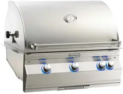
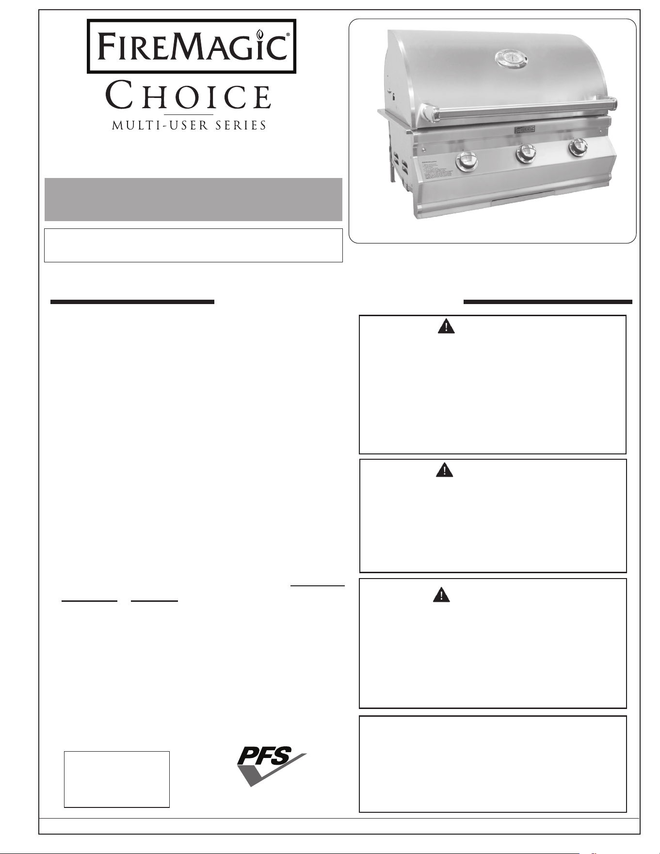
CM540i shown
CM430i, CM540i, and CM650i
2
IMPORTANT: LIRE ATTENTIVEMENT CES INSTRUCTIONS AVANT DE COMMENCER L'INSTALLATION OU L'UTILISATION.
DANGER:
SI VOUS SENTEZ DU GAZ:
• Coupez le gaz de l'appareil.
• Éteignez toute amme nue.
• Ouvrez le couvercle.
• Si l'odeur persiste, éloignez-vous de l'appareil
et appelez immédiatement votre fournisseur de
gaz ou les pompiers.
ATTENTION:
• N'entreposez pas et n'utilisez pas d'essence
ou d'autres liquides ou vapeurs inammables à
proximité de cet appareil ou de tout autre appareil.
• Une bouteille de GPL non connectée pour
utilisation ne doit pas être stockée à proximité de
cet appareil ou de tout autre appareil.
EXIGENCES EN MATIÈRE DE CODE ET
D'APPROVISIONNEMENT: L'installation doit être
conforme aux codes locaux ou, en l'absence de codes
locaux, soit au National Fuel Gas Code, ANSI 2223.1/
NFPA 54, soit au Natural Gas and Propane Installation
Code, CSA B149.1, soit au Code de stockage et de
manipulation du propane, CSA B149.2, selon le cas.
L'appareil de cuisson au gaz extérieur et son robinet
d'arrêt individuel doivent être déconnectés du système
de tuyauterie d'alimentation en gaz pendant tout essai
de pression de ce système à des pressions d'essai
supérieures à
1
/2 psi (3,5 kPa).
L'appareil de cuisson au gaz extérieur doit être isolé du
système de tuyauterie d'alimentation en gaz en fermant
son robinet d'arrêt manuel individuel pendant tout test
de pression du système de tuyauterie d'alimentation
en gaz à des pressions d'essai égales ou inférieures
à
1
/2 psi (3,5 kPa).
Si une source électrique externe est utilisée, l'appareil
à gaz de cuisson extérieur, lorsqu'il est installé,
doit être mis à la terre conformément aux codes
locaux ou, en l'absence de codes locaux, avec
le National Electrical Code, ANSI/NFPA 70, ou le
Canadian Electrical Code. Code, Partie I, CSA C22.1.
Gardez tout cordon d'alimentation électrique et le tuyau
d'alimentation en carburant à l'écart de toute surface
chauée.
ATTENTION:
Une installation, un réglage, une modication, un
entretien ou une maintenance inappropriés peuvent
causer des blessures ou des dommages matériels.
Pour une installation correcte, reportez-vous aux
instructions d'installation. Pour obtenir de l'aide ou des
informations supplémentaires, consultez un technicien
de service professionnel qualifié, une agence de
service ou le fournisseur de gaz.
AVERTISSEMENTS ET CODES DE SÉCURITÉ
Le bon fonctionnement de votre
gril nécessite un entretien rapide et
périodique. Voir la section ENTRETIEN
ET NETTOYAGE pour plus de détails.
Certié à : ANSI Z21.58
CSA 1.6
US
®
C
À UTILISER UNIQUEMENT À L'EXTÉRIEUR
Grille de cuisson US
Numéros de brevet
D857,453
D862,984
Cet appareil est conçu comme un appareil surveillé.
NE PAS laisser cet appareil brûler sans surveillance.
CM430i, CM540i, and CM650i
INSTALLATION ET
LE MANUEL DU PROPRIÉTAIRE
INSTALLATEUR: laissez ces instructions au
consommateur.
CONSOMMATEUR: À conserver pour référence future.
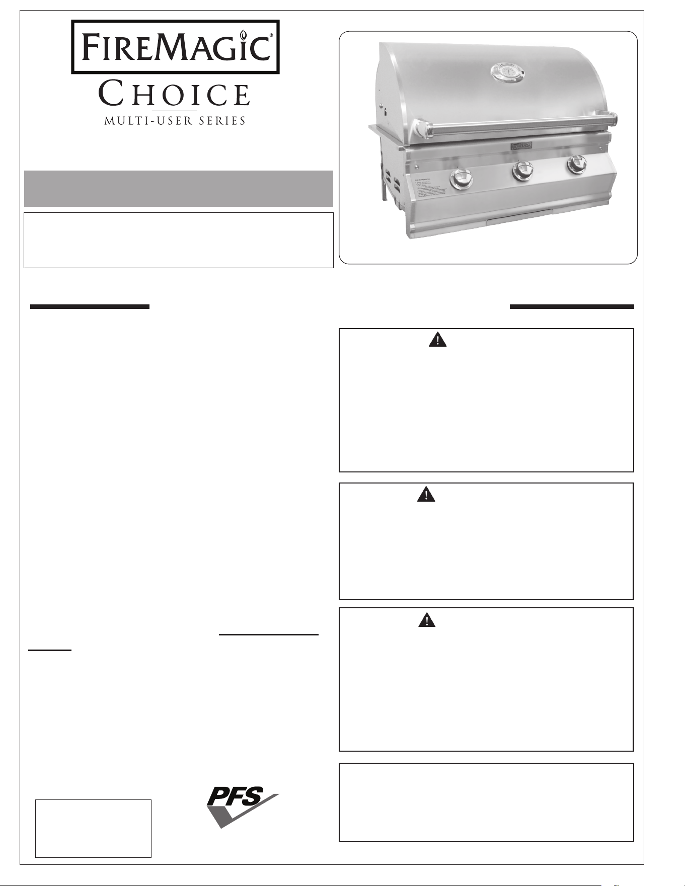
C540i illustré
GRIL À GAZ EXTÉRIEUR INTÉGRÉ
C430i, C540i, et C650i
REV 1 - F - 2601231115
L-C2-603

3
CONTENTS
REV 1 - F - 2601231115
L-C2-603
GETTING STARTED
AVERTISSEMENTS ��������������������������������������������������� 4
INSTALLATION, OPERATION, AND SAFETY
INFORMATION���������������������������������������������������������� 5
GAS SAFETY INFORMATION ���������������������������������� 6
WHEN USING PROPANE GAS ���������������������������������� 6
WHEN USING NATURAL GAS ���������������������������������� 6
INSTALLATION SAFETY GUIDELINES����������������������� 6
OPERATING THE UNIT SAFELY AND CORRECTLY
������������������������������������������������������������������������������������ 6
SAFE USE & MAINTENANCE OF PROPANE GAS
CYLINDERS �������������������������������������������������������������� 7
ENCLOSURE REQUIREMENTS ����������������������������� 11
ENCLOSURE PARAMETERS ����������������������������������� 11
VENTILATION ����������������������������������������������������� 12
INSTALLATION REQUIREMENTS ������������������������ 17
EXHAUST HOOD ������������������������������������������������� 17
CLEARANCES ����������������������������������������������������� 18
DIAGRAMMATICAL REPRESENTATIONS OF
OUTDOOR AREAS �������������������������������������������������� 21
MODEL SPECIFICATIONS ������������������������������������� 22
CHOICE MULTI-USER GRILL REPLACEMENT
PARTS LIST ������������������������������������������������������������� 23
INSTALLATION
INSTALLATION ������������������������������������������������������� 25
BUILD / CONSTRUCT ENCLOSURE ������������������������ 25
INSTALL TIMER BOX �������������������������������������������� 25
INSTALL INSULATING LINER (if applicable) ������������� 25
SLIDE UNIT INTO ENCLOSURE CUTOUT �������������� 25
LEAK TEST ���������������������������������������������������������� 27
INSTALL FLAVOR GRIDS ��������������������������������������� 27
INSTALL COOKING GRIDS ������������������������������������ 27
SECURE COOKING GRIDS ������������������������������������ 28
LOCK CONTROL KNOBS ��������������������������������������� 29
INSTALL DRIP TRAY ��������������������������������������������� 29
OPERATION TEST ��������������������������������������������������� 29
USE, CARE, & SERVICE
IDENTIFICATION OF GRILL CONTROLS ������������ 30
USING THE GRILL �������������������������������������������������� 31
LIGHTING (IGNITION) INSTRUCTIONS �������������� 33
ELECTRONIC LIGHTING �������������������������������������� 33
SETTING THE TIMER ������������������������������������������� 33
MANUAL LIGHTING ��������������������������������������������� 33
SHUTTING OFF THE UNIT ������������������������������������ 33
SERVICING AND CLEANING �������������������������������� 34
CLEANING YOUR GRILL ��������������������������������������� 34
CONTROL PANEL REMOVAL ��������������������������������� 36
COOKING GRID REMOVAL ����������������������������������� 37
BURNER REMOVAL ���������������������������������������������� 38
WARMING RACK REMOVAL ���������������������������������� 38
CONVERTING THE GAS TYPE ������������������������������� 39
AIR SHUTTER ADJUSTMENT / BURNER FLAME
INSPECTION
������������������������������������������������������� 40
VALVE "LOW" SETTING ADJUSTMENT ������������������� 41
NOTES PAGE ����������������������������������������������������������� 42
TROUBLESHOOTING ��������������������������������������������� 43
WARRANTY ������������������������������������������������������������ 44
COMMONWEALTH OF MASSACHUSETTS
REQUIREMENTS
�������������������������������������������������� 44
4
Avertissements généraux :
• Cet appareil est destiné à une utilisation en extérieur uniquement. Si l'appareil est entreposé
à l'intérieur, retirez les bouteilles et gardez-les à l'extérieur.
• Ne couvrez pas immédiatement l'appareil après utilisation. Laissez-le refroidir avant de le
couvrir, de le déplacer ou de le ranger. Ne pas respecter cette mesure de sécurité pourrait
entraîner un incendie causant des dommages matériels, des blessures ou la mort.
• Ne pas utiliser cet appareil sous une surface combustible.
• Ne pas utiliser cet appareil sous un auvent. Le non respect de cette mesure de sécurité pourrait
entraîner un incendie ou des blessures.
• Tous les dégagements minimaux détaillés dans la section INSTALLATION REQUIREMENTS
DOIVENT être respectés.
• Un régulateur de pression de gaz doit être utilisé avec cet appareil de cuisson à gaz pour
l'extérieur. Ce régulateur doit être réglé pour une pression de sortie de 5 pouces colonne d'eau
pour le gaz naturel et de 10 pouces pour le propane. Veuillez consulter la liste des pièces de
ce manuel du propriétaire pour vérier si un régulateur est inclus avec votre appareil.
• LE RÉGULATEUR DOIT ÊTRE ÉVALUÉ POUR UN MAXIMUM DE 1/2 (LIVRES PAR POUCES
CARRÉS). Veuillez consulter la liste des pièces de ce manuel du propriétaire pour vérier si
un régulateur est inclus avec votre appareil. SI VOTRE OFFRE DE GAZ EST SUPÉRIEURE
DE 1/2 (LIVRES PAR POUCES CARRÉS), UN RÉGULATEUR ADDITIONNEL DOIT ÊTRE
INSTALLÉ AVANT L'UTILISATION DE L'APPAREIL. VEUILLEZ CONSULTER LA SECTION
DES CONDITIONS D'ALIMENTATION EN GAZ POUR LA PRESSION APPROPRIÉE DE
L'ALIMENTATION EN GAZ.
• Ne couvrez jamais la surface entière de cuisine ou de gril de gaureuses ou de casseroles.
La surchaue se produira et les brûleurs ne seront pas très performants quand la chaleur de
combustion est emprisonnée au-dessous de la surface à cuire.
• Ne jamais pulvériser d'eau sur une unité de gaz chaude, car cela peut endommager les surfaces
ou les composants.
Avertissements de propane :
• Une fuite de GPL peut causer une incendie ou une explosion si enammée entraînant des
blessures corporelles graves ou la mort.
• Communiquez avec le fournisseur de GPL pour les réparations ou pour disposer de qules
bouteille ou du GPL non utilisé.
AVERTISSEMENTS
5
WARNING: NEVER cover more than 75% of the cooking or grill surface with griddles, pots, or pans. Overheating will
occur, and burners will not perform properly when combustion heat is trapped below the cooking surface.
IMPORTANT: IN THE EVENT OF A GREASE FIRE, IMMEDIATELY SHUT OFF THE MAIN GAS VALVE TO THE UNIT.
KEEP THE LID OPEN AND ALLOW THE FIRE TO EXTINGUISH ITSELF. KEEP AT A SAFE DISTANCE. A THOROUGH
INSPECTION BY A QUALIFIED PROFESSIONAL SERVICE TECHNICIAN SHOULD BE CONDUCTED BEFORE FUTURE
USE OF YOUR UNIT. THE SERVICE TECHNICIAN WILL CHECK THE SYSTEM FOR GAS LEAKS AND WILL CHECK ALL
ELECTRICAL WIRING FOR DAMAGE. ALL GAS LEAKS AND WIRING MUST BE REPAIRED PRIOR TO FUTURE USE.
1. Wear gloves and use extreme caution whenever installing
and handling this product and its accessories as certain
components have sharp edges that can cause personal
injury.
2. The outdoor appliance and surrounding area MUST remain
clear of ammable substances such as gasoline, yard
debris, wood, etc. Maintain a minimum horizontal clearance
of 18" (in all directions) from combustible materials/items.
3. Do not block the front air inlet along the bottom of the
control panel. See the COMBUSTION AIR AND COOLING
AIRFLOW section under INSTALLATION REQUIREMENTS
for details.
4. This unit must be installed so that the required vent
openings and surrounding area of the enclosure
remain clear and free at all times. See the ENCLOSURE
REQUIREMENTS section for details.
5. When using propane gas: the propane cylinder,
regulator, and rubber hose must be in a location not
subject to temperatures above 125° F (51° C).
6. Before each use, ensure the ames on each burner burn
evenly along the entire burner with a steady ame (mostly
blue). If burner ames are not normal, check and clean
the orice and burner/venturi tubes for insects and insect
nests. A clogged tube can lead to a re beneath the unit.
A proper ame pattern will ensure safe operation and
optimal performance. Adjust the air shutter as needed
to achieve proper ame pattern (see AIR SHUTTER
ADJUSTMENT/BURNER FLAME INSPECTION section,
under SERVICING AND CLEANING for details).
7. The in-line gas valve or gas cylinder valve must always
be shut OFF when the unit is not in use.
8. Adults MUST be present when this gas appliance is
operating. This appliance MUST NOT be left burning
when unattended.
9. Do not store combustible materials in the enclosure
directly beneath the appliance.
CAUTION: FOR YOUR SAFETY, you must provide openings in the enclosure for replacement air and ventilation
(in case of possible leakage from gas connections or propane cylinders). Failure to do so may
result in a re or explosion causing property damage, bodily injury, or death. See the ENCLOSURE
REQUIREMENTS section for details.
The unit serial number tag can be found axed to the grill body behind the control panel (on an
aluminum tag) and on the underside of the drip tray handle (on a thermal label). It is recommended
that the drip tray rst be removed and cleaned / emptied of its contents, then turned over to view.
The unit rating label is located inside of the control panel.
WARNING
NEVER cover slots, holes, or passages in the oven
bottom or cover an entire rack with material such as
aluminum foil. Doing so blocks air ow through the
oven and may cause carbon monoxide poisoning.
Aluminum foil linings may trap heat causing a re
hazard.
INSTALLATION, OPERATION, AND SAFETY INFORMATION
6
WHEN OPERATING THIS GAS APPLIANCE, ALL INSTRUCTIONS AND WARNINGS
MUST BE OBSERVED. FAILURE TO DO SO MAY RESULT IN A FIRE OR EXPLOSION
CAUSING PROPERTY DAMAGE, BODILY INJURY, OR DEATH.
Every time you use the unit, make sure that:
1. The area around the unit is clear and free from combustible materials, gasoline and ammable vapours and
liquids.
2. There is no blockage of the airow through the vent openings located on the enclosure.
3. The hose is inspected (if applicable). See SAFE USE & MAINTENANCE OF PROPANE-GAS CYLINDERS
section.
DO NOT store any combustible materials, gasoline, and any other ammable vapours/liquids in the vicinity of
the unit. Provide adequate clearance for servicing and operation.
WARNING
This gas appliance and its enclosure MUST be plumbed and vented in accordance with local building
and safety codes and should be approved by local code enforcement ocials. This appliance MUST be
installed and operated according to the information below.
FAILURE TO PROPERLY VENT THE ENCLOSURE MAY RESULT IN A FIRE OR EXPLOSION CAUSING
PROPERTY DAMAGE, BODILY INJURY, OR DEATH.
A leaking gas connection or valve unintentionally left open will create a hazard.
WHEN USING PROPANE GAS
• Propane gas (also known as L.P. gas) is heavier than air and will accumulate or pool in an inadequately
vented enclosure or recessed area.
• If a pool of propane gas is ignited, an explosion will occur. Adequate venting at the oor level, or the lowest
point where gas could accumulate, will eliminate this danger.
Refer to the ENCLOSURE REQUIREMENTS section.
Observe all local codes.
• DO NOT store a spare propane-gas cylinder under or near the enclosure.
WHEN USING NATURAL GAS
• Natural gas is lighter than air and will accumulate at the top of an inadequately vented enclosure.
• If an accumulation of natural gas is ignited, an explosion will occur. Adequate venting at the top of the
enclosure, or the highest point where gas could accumulate, will eliminate this danger.
Refer to the ENCLOSURE REQUIREMENTS section.
Observe all local codes.
INSTALLATION SAFETY GUIDELINES
THIS UNIT MUST BE INSTALLED SO THAT THE REQUIRED VENT OPENINGS AND SURROUNDING AREA
OF THE ENCLOSURE REMAIN CLEAR AND FREE AT ALL TIMES. See the ENCLOSURE REQUIREMENTS
section for details.
CAUTION: FOR YOUR SAFETY, you must provide openings in the enclosure for replacement air and
ventilation (in case of possible leakage from gas connections or propane cylinders). Failure
to do so may result in a re or explosion causing property damage, bodily injury, or death.
See the ENCLOSURE REQUIREMENTS section for details.
The gas cylinder, regulator, and rubber hose must be in a location not subject to temperatures above
125° F (51° C).
IF A PROPANE CYLINDER IS INSTALLED INSIDE OF THE ENCLOSURE, THE GUIDELINES FOUND IN THE
ENCLOSURE REQUIREMENTS SECTION MUST BE FOLLOWED.
GAS SAFETY INFORMATION
OPERATING THE UNIT SAFELY AND CORRECTLY
7
IMPORTANT FOR YOUR SAFETY
READ AND FOLLOW ALL WARNINGS PROVIDED WITH THE PROPANE-GAS CYLINDER.
When operating this appliance with a propane-gas cylinder, these instructions and warnings MUST be observed.
FAILURE TO DO SO MAY RESULT IN A SERIOUS FIRE OR EXPLOSION.
CYLINDER/CONNECTOR REQUIREMENTS
a. Propane-gas cylinders, valves, and hoses must be
maintained in good condition and inspected before each use
of appliance. They must be replaced if there is any visible
damage. If hose is cut or shows excessive abrasion or wear,
it must be replaced before using appliance (see e.).
b. This unit, when used with a cylinder, should be connected
to a standard 5-gallon (20 lb.) propane-gas cylinder
equipped with a listed overlling prevention device. The
device has been required on all cylinders sold since
October 1,1998, to prevent overlling.
c. Cylinder dimensions should be approximately 12" (30.5
cm) in diameter and 18" (45.7 cm) high. Cylinders must
be constructed and marked in accordance with the U.S.
Department of Transportation (D.O.T.) Specications for
LP-Gas Cylinders, or the Standard for Cylinders, Spheres,
and Tubes for Transportation of Dangerous Goods and
Commission, CAN/CSA-B339, as applicable.
d. The cylinder used must include a collar to protect the
cylinder valve. The cylinder supply system must be
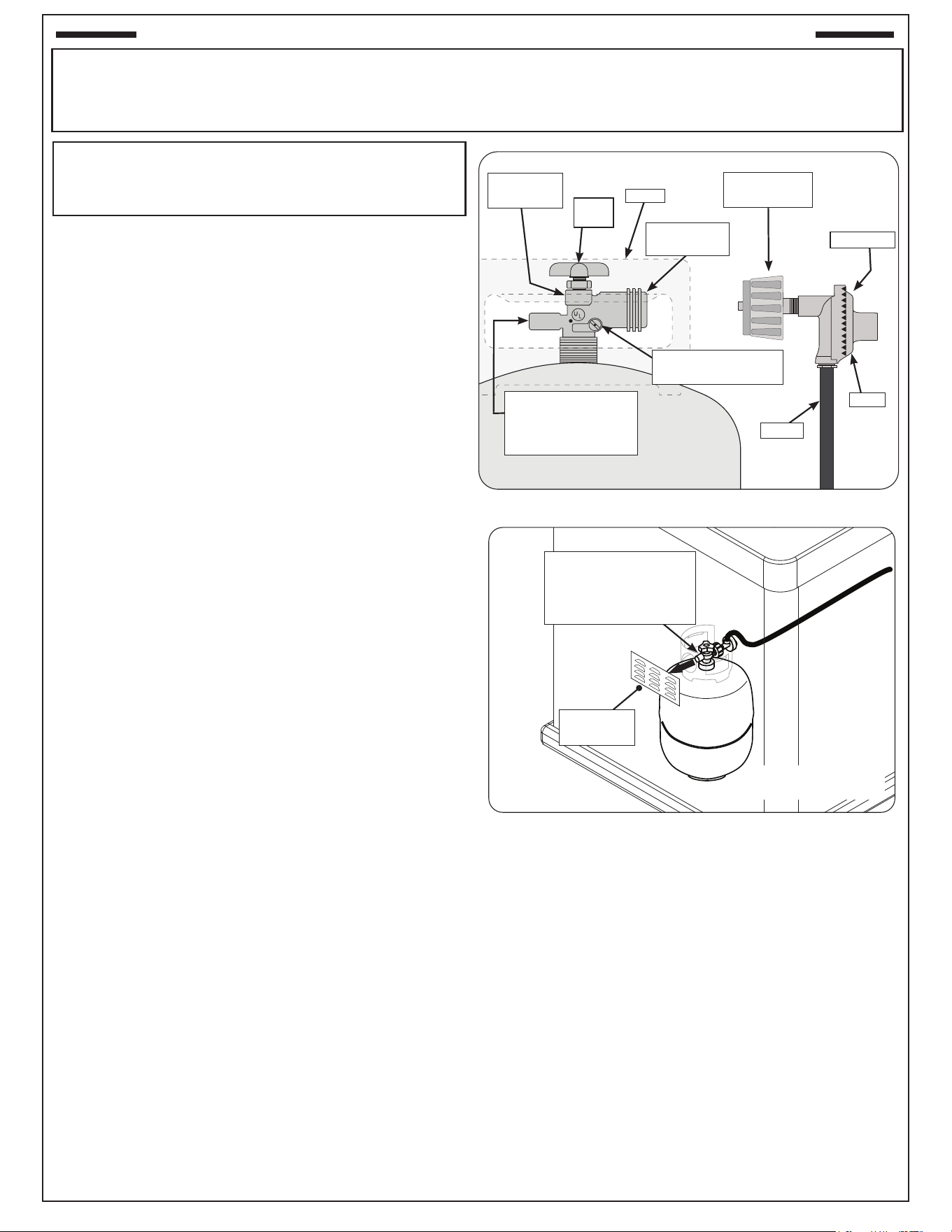
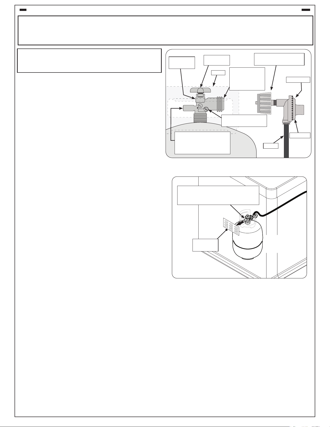
arranged for vapour withdrawal. See Fig. 7-1.
e. When used with a cylinder, the gas supply system must
be used with a pressure regulator. The pressure regulator
and hose assembly (not supplied) used must match the
specication for Type I by ANSI Z 21.58/CGA 1.6 and
must comply with UL 144 as a part of the self-contained
LP gas supply system (see Fig. 7-1).
f. The propane-gas cylinder valve must be equipped with
a cylinder connection device, described as Type I in the
standard dened in paragraph e. above. This device is
commonly described as an Acme thread coupler.
g. If the cylinder comes with a dust plug, place it on the
cylinder valve outlet whenever the cylinder is not in use.
Only install the type of dust cap on the cylinder valve outlet
that is provided with the cylinder valve. Other types of caps
or plugs may result in leakage of propane.
COUPLER OPERATION
To connect the regulator/hose assembly to the propane-
gas cylinder valve tting: Press the hand nut on the regulator
over the Acme thread tting on the cylinder valve. Turn the
hand nut clockwise to engage the threads and tighten until
snug. The use of pliers or a wrench should not be necessary.
Only cylinders marked “propane” may be used.
To disconnect: Turn the hand nut counterclockwise until
detached (Fig. 7-1).
Fig. 7-1 Type I Acme thread coupler
QCC Type 1
valve
Pressure relief valve
for vapour withdrawal
(point toward vent
openings)
Brass Acme
thread tting
Hand
wheel
Hand nut with
Acme thread
Liquid level indicator
(optional)
Hose
Regulator
Vent
Collar
Fig. 7-2 Vapour withdrawal detail
Point pressure relief
valve toward vent
opening for vapour
withdrawal
Vent
opening
(Location and
design may vary)
For requirements related to ventilation,
L.P. Cylinders, and the enclosure, see the
ENCLOSURE REQUIREMENTS section.
SAFE USE & MAINTENANCE OF PROPANE GAS CYLINDERS
8
IMPORTANT POUR VOTRE SÛRETÉ
LISEZ ET SUIVEZ TOUS LES AVERTISSEMENTS ÉQUIPÉS DE VOTRE CYLINDRE DE GAZ DE PROPANE.
En actionnant cet appareil avec un cylindre de gaz de propane ON DOIT observer ces instructions et avertissements.
LE MANQUE DE FAIRE AINSI PEUT AVOIR COMME CONSÉQUENCE UNE INCENDIE OU UNE EXPLOSION SÉRIEUSE.
CYLINDRE ET CONDITIONS ET
CARACTÉRISTIQUES DE CONNECTEUR
a. Les bouteilles, les vannes et les tuyaux de propane doivent
être entretenus et inspectés avant chaque utilisation. Ils
doivent être remplacés en cas de dommages visibles. Si
le tuyau est coupé ou présente des signes d’abrasion ou
d’usure, il doit être remplacé avant utilisation (voir e.).
b. Cette unité, lorsqu'elle est utilisée avec une bouteille, doit
être connectée à une bouteille standard de gaz propane de
5 gallons (20 lb) équipée d'un dispositif anti-débordement
répertorié. L’appareil est obligatoire sur toutes les bouteilles
vendues depuis le 1er octobre 1998 an d’empêcher tout
remplissage excessif.
c. Les dimensions du cylindre doivent être d'environ 12 " (30,5 cm)
de diamètre et 18" (45,7 cm) de hauteur. Les bouteilles doivent
être construites et marquées conformément aux spécications
du ministère des Transports (DOT) pour les bouteilles à gaz LP
ou à la norme relative aux bouteilles, sphères et tubes pour le
transport des marchandises dangereuses et à la Commission,
CAN / CSA-B339, selon le cas.
d. La bouteille utilisée doit comporter un collier pour protéger le
robinet de la bouteille. Le système d'alimentation de la bouteille
doit être conçu pour le retrait de la vapeur. Voir Fig. 8-1.
e. Lorsqu'il est utilisé avec une bouteille, le système
d'alimentation en gaz doit être utilisé avec un régulateur
de pression. Le régulateur de pression et l'ensemble
de tuyau (non fourni) utilisés doivent correspondre à la
spécication de type I par ANSI Z 21.58/CGA 1.6 et doivent
être conformes à UL 144 en tant que partie du système
d'alimentation en gaz propane autonome (voir Fig. 8-1).
f. La valve de cylindre de gaz de propane doit être équipée
d’un dispositif d’accouplement de raccordement de
cylindre, décrit comme type I dans la norme dénie dans le
e. de paragraphe ci-dessus. Ce dispositif est généralement
décrit comme coupleur de l de point culminant.
g. Si la bouteille est livrée avec un bouchon anti-poussière,
placez-le sur la sortie du robinet de la bouteille chaque fois
que la bouteille n'est pas utilisée. Installez uniquement le
type de capuchon anti-poussière sur la sortie du robinet
de la bouteille qui est fourni avec le robinet de la bouteille.
D'autres types de bouchons ou de bouchons peuvent
entraîner des fuites de propane.
OPÉRATION DE COUPLEUR
Pour relier le regulator/hose à l’ajustage de précision de
valve de cylindre de gaz de propane: Serrez l’écrou de main
sur le régulateur au-dessus de l’ajustage de précision de l de
point culminant sur la valve de cylindre. Tournez l’écrou de main
dans le sens des aiguilles d’une montre pour engager les ls
et pour serrer jusqu’à ce que douillettement. L’utilisation des
pinces ou de la clé ne devrait pas être nécessaire. Seulement
le "propane" marqué par cylindres doit être employé.
Pour déconnecter: tournez l'écrou à main dans le sens
antihoraire jusqu'à ce qu'il soit détaché (Fig. 8-1)
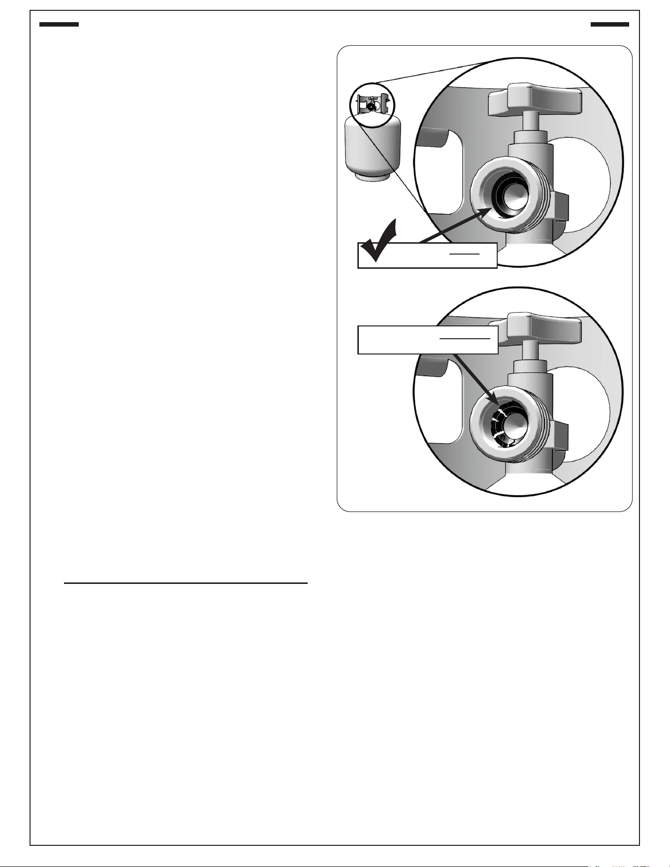
Fig. 8-1 Type coupleur de l de point culminant d’I
QCC Type 1
valve
Valve de décompression
pour prélèvement de
vapeur (pointez vers les
ouvertures de ventilation)
Ajustage de
précision en
laiton de l de
point culminant
Volant de
commande
Écrou de main avec le
l de point culminant.
Indicateur de niveau
de liquide (facultatif)
Tuyau
Régulateur
Passage
Collar
Fig. 8-2 Détail du retrait de vapeur
Pointez la soupape de surpression
vers l'ouverture d'évent pour le
retrait de la vapeur
Ouverture
d'aération
(L'emplacement
et la conception
peuvent varier)
Pour les exigences relatives à la ventilation, aux
bouteilles de GPL et à l'enceinte, reportez-vous à
la section ENCLOSURE REQUIREMENTS.
UTILISATION SÛRE ET ENTRETIEN DES CYLINDRES DE GAZ DE PROPANE
9
Important: Before using the unit, and after each time
the cylinder is removed and reattached,
check the hose for wear (see a.) and check
all connections for leaks. Turn o the unit
valves and open the main cylinder valve,
then check connections with soapy water.
NEVER USE A FLAME TO CHECK FOR
LEAKS. Repair any leaks before lighting
the unit.
CAUTION: Always turn the propane cylinder main
valve o after each use, and before moving
the unit and cylinder or disconnecting the
coupling. This valve must remain closed
and the cylinder disconnected while the
appliance is not in use, even though the gas
ow is stopped by a safety feature when the
coupler is disconnected.
Carefully inspect the hose assembly each time before
the gas is turned on. A cracked or frayed hose must be
replaced immediately.
If the appliance is stored indoors, the cylinder must be
disconnected and removed. Disconnected cylinders must
be stored outdoors, out of the reach of children, with
threaded valve plugs tightly installed, and must not be
stored in a building, garage, or any other enclosed area.
FOR YOUR SAFETY
A. DO NOT store a spare propane-gas cylinder under
or near this appliance.
B. NEVER ll the cylinder beyond 80-percent full.
C. IF THE INFORMATION IN a. AND b. IS NOT
FOLLOWED EXACTLY, A FIRE CAUSING DEATH
OR SERIOUS INJURY MAY OCCUR.
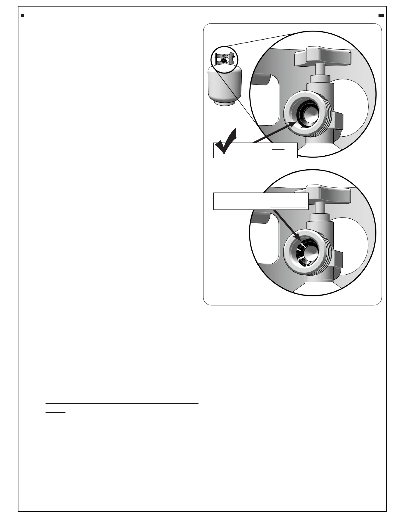
D. CGA 791 connections on LP gas cylinders: The
cylinder face elastomeric face seal element on
these devices could, over time, show marked and
visible damage or deterioration that might cause a
leak even with the connection tightened. A visual
inspection for the seal must be carried out every time
a LP gas cylinder is replaced or relled. Any LP gas
cylinder showing signs of damage or deterioration
as illustrated in Fig. 9-1, including visible cracks and
pitting, must be replaced.
Fig. 9-1 Inspect rubber seal
Example of GOOD
RUBBER SEAL
Example of DAMAGED
RUBBER SEAL
X
SAFE USE & MAINTENANCE OF PROPANE GAS CYLINDERS (Cont.)
10
Important: Avant d’employer le unité, et ensuite
chaque fois que le cylindre est
enlevé et rattaché, examinez tous les
raccordements pour déceler les fuites.
Arrêtez les valves de unité et ouvrez
la valve principale de cylindre, puis
vériez les raccordements avec de l’eau
savonneux. NE JAMAIS UTILISER
UNE FLAMME POUR DÉTECTER DES
FUITES. Réparez toutes les fuites avant
d’allumer le unité.
ATTENTION: Tournez toujours la valve principale
de cylindre de propane au loin après
chaque utilisation, et avant de déplacer
le unité et le cylindre, ou débrancher
l’accouplement. Cette valve doit rester
fermée et le cylindre a débranché alors
que l’appareil n’est pas en service,
quoique l’écoulement de gaz soit arrêté
par un dispositif de sûreté quand le
coupleur est débranché.
Inspectez soigneusement l’ensemble de tuyau chaque
fois avant que le gaz soit allumé. Un tuyau ssuré ou
eloché doit être immédiatement remplacé.
Si l'appareil est stocké à l'intérieur, le cylindre doit être
disconnected et a enlevé. Des cylindres Disconnected
doivent être stockés dehors, hors de la portée des enfants,
avec les prises de valve letées étroitement installées, et
ne doivent pas être stockés dans un bâtiment, le garage,
ou n'importe quel autre secteur inclus.
POUR VOTRE SÛRETÉ
a. Ne stockez pas un cylindre de gaz disponible de
propane dessous ou ne vous approchez pas de
cet appareil.
b. Ne remplissez jamais cylindre au delà de 80 pour
cent de plein.
c. SI L’INFORMATION DANS “A” ET “B” N’EST PAS
SUIVIE EXACTEMENT, UN FEU CAUSANT LA
MORT OU DES DOMMAGES SÉRIEUX PEUT
SE PRODUIRE.
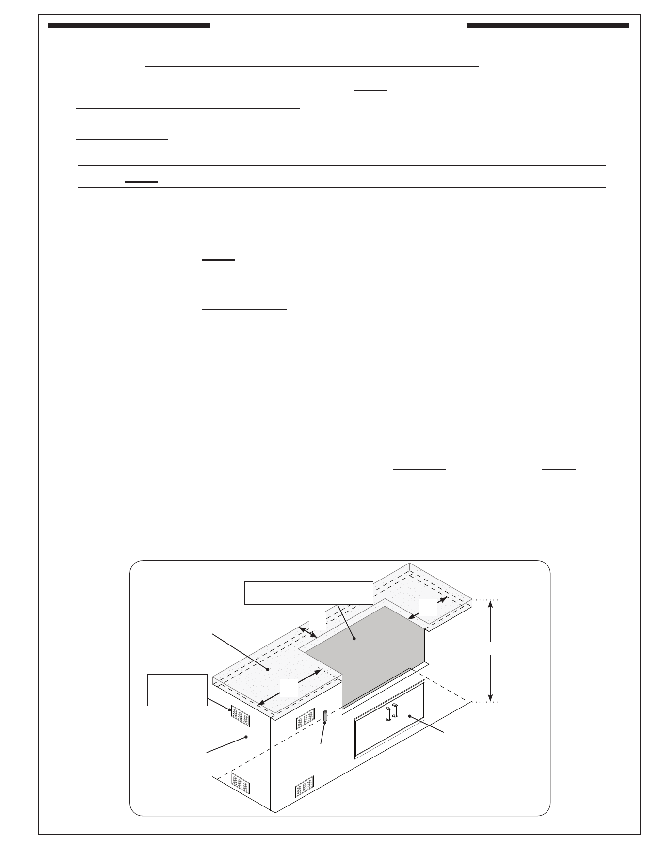
d. Connexions CGA 791 sur les bouteilles de
GPL : l'élément d'étanchéité en élastomère de
la face de la bouteille de ces appareils peut, au
l du temps, présenter des dommages ou une
détérioration marqués et visibles susceptibles
de provoquer une fuite même avec la connexion
serrée. Une inspection visuelle du joint doit être
eectuée chaque fois qu'une bouteille de GPL
est remplacée ou remplie. Toute bouteille de
GPL présentant des signes de dommages ou
de détérioration, tel qu'illustré à la Fig. 10-1, y
compris des ssures et des piqûres visibles, doit
être remplacée.
Fig. 10-1 Inspecter le joint en caoutchouc
Exemple de BIEN
JOINT EN CAOUTCHOUC
Exemple de JOINT EN
CAOUTCHOUC ENDOMMAGÉ
X
UTILISATION SÛRE ET ENTRETIEN DES CYLINDRES DE GAZ DE PROPANE (suite)
11
GFRC islands are available (for select models). They meet all enclosure and ventilation requirements. Contact
your local dealer. For requirements regarding custom-built enclosures, see below.
To ensure proper operation and safety, the enclosure MUST comply with the following:
• Proper construction and cutout openings - see INSTALLATION REQUIREMENTS and ENCLOSURE
PARAMETERS sections.
• Proper ventilation - see VENTILATION section.
• Proper clearances - see INSTALLATION REQUIREMENTS section.
You MUST read and follow these sections for complete enclosure requirement details.
ENCLOSURE PARAMETERS
General Guidelines
The enclosure can be constructed according to your individual preference, while following all guidelines found in
this manual. The enclosure MUST (see Fig. 11-1):
• be installed on a hard and level surface
• be properly vented (see VENTILATION section)
• have a countertop that is non-combustible (enclosure may be combustible construction with proper provision*)
• have the minimum dimensions specied in Fig. 11-1
• have the minimum cutout dimensions (see CUTOUT DIMENSIONS section)
• have access to the interior for ease of installation and service
• be setup so the unit is as close to the vent openings as possible
• be designed so that the grill is supported by the stainless-steel hanger extending from the upper portion of
the unit (rests on left, right, and back of the countertop cutout), and the two front support adjustment bolts
located below the control panel (left and right sides) - see INSTALLATION section
• have drainage cutouts (if needed) to prevent the accumulation of water within the enclosure
• meet all requirements found in Fig. 11-1 and the following sections
* When installing this unit in a combustible enclosure, an approved insulating liner MUST be used.
Reference Table 3 in the MODEL SPECIFICATIONS section for liner model #.
When an L.P. cylinder is used in the enclosure, additional requirements exist, see the L.P. CYLINDER
REQUIREMENTS section.
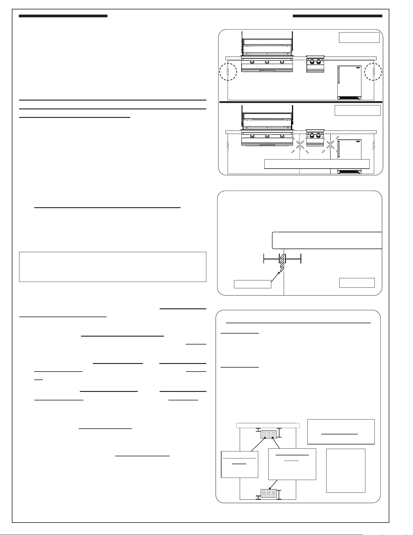
Fig. 11-1 Enclosure specications
Gas supply
(if applicable)
• Not to scale
• Example shown, design and location
of enclosure and its items may vary
Ventilation
(see following
section)
Access door
32-40"
Countertop
(non-combustible)
Enclosure
(combustible* or
non-combustible)
* insulating liner required
(sold separately)
Grill Cutout
(see Cutout Dimensions section)
8"
min.
t
8"
min.
t
6"
▲
min.
t Countertop minimum width measures from
cutout edge to side wall inner dimension
▲
Minimum measurement from edge of cutout
to edge of countertop
ENCLOSURE REQUIREMENTS
12
Min.
90˚
Min.
90˚
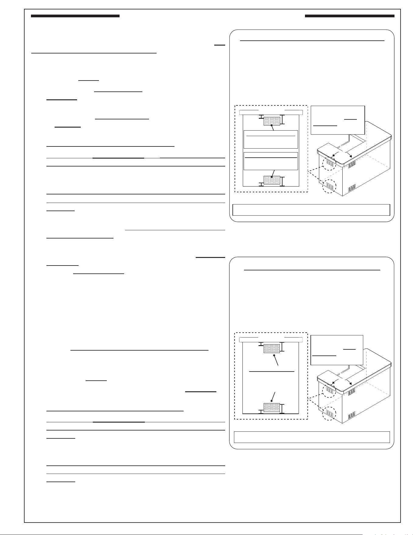
• 6" min. clearance between all vent openings
and any items outside of enclosure
• 2" min. clearance between all vent openings
and any items within enclosure
Fig. 12-2 Vent openings clearance
2"
min.
(Side View)
6"
min.
Vent opening
VENTILATION
FOR YOUR SAFETY, you must provide the openings
specic to your gas type for replacement air and
ventilation of the enclosure (in case of possible leakage
from gas connections and L.P. cylinders as applicable,
and for heat dissipation). See the following sections
for ventilation requirements specic to your gas type.
Failure to provide proper ventilation for your gas type
may result in a re or explosion causing property
damage, bodily injury, or death.
WARNING: Vent openings in side walls shall not
communicate directly with other enclosures
of the outdoor cooking gas appliance (see
Fig. 12-1).
• Ventilation openings shall not be located in front
of the appliance above oor level.
• Every opening shall have a minimum dimension so
as to permit the entrance of a
3
/16" (4.8 mm) rod.
• The openings must remain unobstructed:
The clearance between the openings and any items
outside of the enclosure is a minimum of 6". The
clearance between the openings and any items within
the enclosure is a minimum of 2". See Fig. 12-2.
Natural Gas Ventilation Requirements
When natural gas is used in the enclosure, the guidelines
below MUST be followed:
One side of the enclosure shall be left completely open
to the outside; OR 1 minimum vent opening (at top level)
or 2 vent openings (1 at top and 1 at oor level) MUST
be created (reference Fig. 12-3):
• When using only 1 vent opening: the opening must
be at top level and must have a minimum of 20 sq.
in. of free area.
• When using 2 vent openings: The top and oor
level openings must have a minimum of 10 sq. in. of
free area each. The openings must be equally sized
(ventilation total of 20 sq. in. free area).
• The opening at the top level must begin 1" or less
below the countertop level and end no more than 5"
below the countertop level.
• If applicable, the opening at the oor level must begin
1" or less above the oor level and end no more than
5" above the oor level.
• If planning for 2 vent openings, it is acceptable to use
RHP venting panels (PN 5510-01). Contact your dealer.
Note: These same requirements apply when multiple
appliances exist in the enclosure.
KEEP THE REQUIRED VENT OPENINGS AND
SURROUNDING AREA OF THE ENCLOSURE
CLEAR AND FREE AT ALL TIMES.
Fig. 12-3 Natural gas ventilation detail
NATURAL GAS VENTILATION REQUIREMENTS:
1 Vent Setup:
• Minimum 1 opening (at top level)
• Top opening: min. 20 sq. in. of free area, within 5"
of countertop
2 Vent Setup:
• 2 openings (1 at top & 1 at oor level)
• Top opening: within 5" of countertop (see below)
• Floor opening: within 5" of oor (see below)
• Each vent opening: min. 10 sq. in. of free area
• Total = 20 sq. in. free area
1"
max.
Keep surrounding area
and vent openings clear
and free at all times.
5"
max.
1"
max.
5"
max.
Note: Vent
openings
example
shown. Your
design may
vary.
(Side view)
1 vent opening
option:
20 sq. in. free
area min.
2 vent opening
option:
10 sq. in. free area
min. (each opening)
(Total = 20 sq. in.)
Fig. 12-1 Correct / Incorrect side wall venting
CORRECT
INCORRECT
(side wall vents cannot communicate)
ENCLOSURE REQUIREMENTS (Cont.)
13
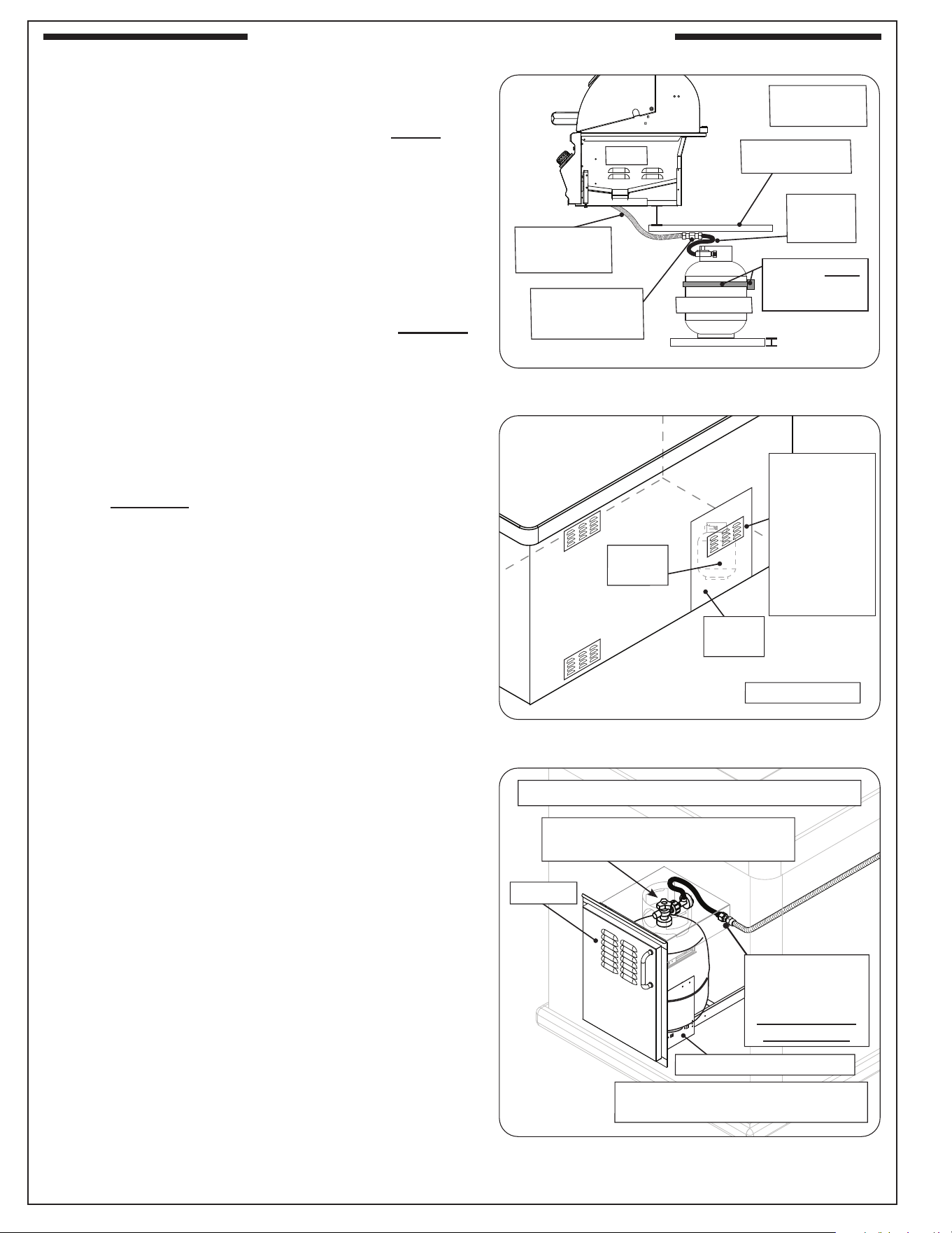
Fig. 13-2 Remote LP ventilation detail
Min.
90˚
Min.
90˚
REMOTE LP VENTILATION REQUIREMENTS:
• Minimum 4 openings (2 at top & 2 at oor level)
• 2 per adjacent wall - spaced at min. 90 degrees
• Top openings: within 5" of countertop (see below)
• Floor openings: within 5" of oor (see below)
• Each vent opening: min. 45 sq. in. of free area
• Total = 180 sq. in. free area
1"
max.
Keep surrounding
area and vent
openings clear and
free at all times.
5"
max.
1"
max.
5"
max.
Vent openings (4)
45 sq. in. of free
area min. (each)
(Total = 180 sq. in.)
Note: Vent openings example shown. Your design may vary.
(Rear view)
L.P. Cylinder Ventilation Requirements
When an L.P. cylinder is used in the enclosure, the
guidelines below MUST be followed:
One side of the enclosure shall be left completely open to
the outside; OR 4 minimum vent openings (2 at top and 2
at oor level) MUST be created (reference Fig. 13-1):
• Each opening at the top level must have a minimum of
10 sq. in. of free area. The openings must be equally
sized.
• Each opening at the oor level must have a minimum
of 5 sq. in. of free area. The openings must be equally
sized.
• Ventilation total of 30 sq. in. free area
• Each opening at the top level must be on adjacent walls
of the enclosure, and spaced at a minimum of 90 degrees.
The openings must begin 1" or less below the countertop
level and end no more than 5" below the countertop level.
• Each opening at the oor level must be on adjacent
walls of the enclosure, and spaced at a minimum of 90
degrees. The openings must begin 1" or less above the
oor level and end no more than 5" above the oor level.
• The above outlined is the minimum ventilation requirement
for each L.P. cylinder used within the enclosure.
• For L.P. cylinders larger than 20 lb capacity, there must
be a minimum of 1 in²/lb of open area for top vent
openings and a minimum of
1
/2 in²/lb of open area for
bottom vent openings.
Note: These same requirements apply for each individual
L.P. cylinder being used within the enclosure.
• Additional requirements exist for L.P. cylinders, see
the L.P. CYLINDER REQUIREMENTS section.
Remote L.P. Ventilation Requirements
When a remote L.P. gas system is used with the
enclosure, the guidelines below MUST be followed:
One side of the enclosure shall be left completely open to
the outside; OR 4 minimum vent openings (2 at top and
2 at oor level) MUST be created (reference Fig. 13-2):
• Each opening must have a minimum of 45 sq. in. of
free area. The openings must be equally sized.
• Ventilation total of 180 sq. in. free area
• Each opening at the top level must be on adjacent side
walls of the enclosure, and spaced at a minimum of 90
degrees. The openings must begin 1" or less below the
countertop level and end no more than 5" below the
countertop level.
• Each opening at the oor level must be on adjacent
walls of the enclosure, and spaced at a minimum of 90
degrees. The openings must begin 1" or less above the
oor level and end no more than 5" above the oor level.
Note: These same requirements apply when multiple
appliances exist in the enclosure.
Fig. 13-1 L.P. cylinder ventilation detail
Min.
90˚
Min.
90˚
L.P. CYLINDER VENTILATION REQUIREMENTS:
• Minimum 4 openings (2 at top & 2 at oor level)
• 2 per adjacent wall - spaced at min. 90 degrees
• Top openings: min. 10 sq. in. of free area each,
within 5" of countertop (20 sq. in. top ventilation)
• Floor openings: min. 5 sq. in. of free area each,
within 5" of oor (10 sq. in. oor ventilation)
• Total = 30 sq. in. free area
1"
max.
Keep surrounding
area and vent
openings clear and
free at all times.
5"
max.
1"
max.
5"
max.
Note: Vent openings example shown. Your design may vary.
(Rear view)
Top vent openings (2)
10 sq. in. free area min.
(each) (Total = 20 sq. in.)
Floor vent openings (2)
5 sq. in. free area min.
(each) (Total = 10 sq. in.)
(Side view)
(Side view)
ENCLOSURE REQUIREMENTS (Cont.)
14
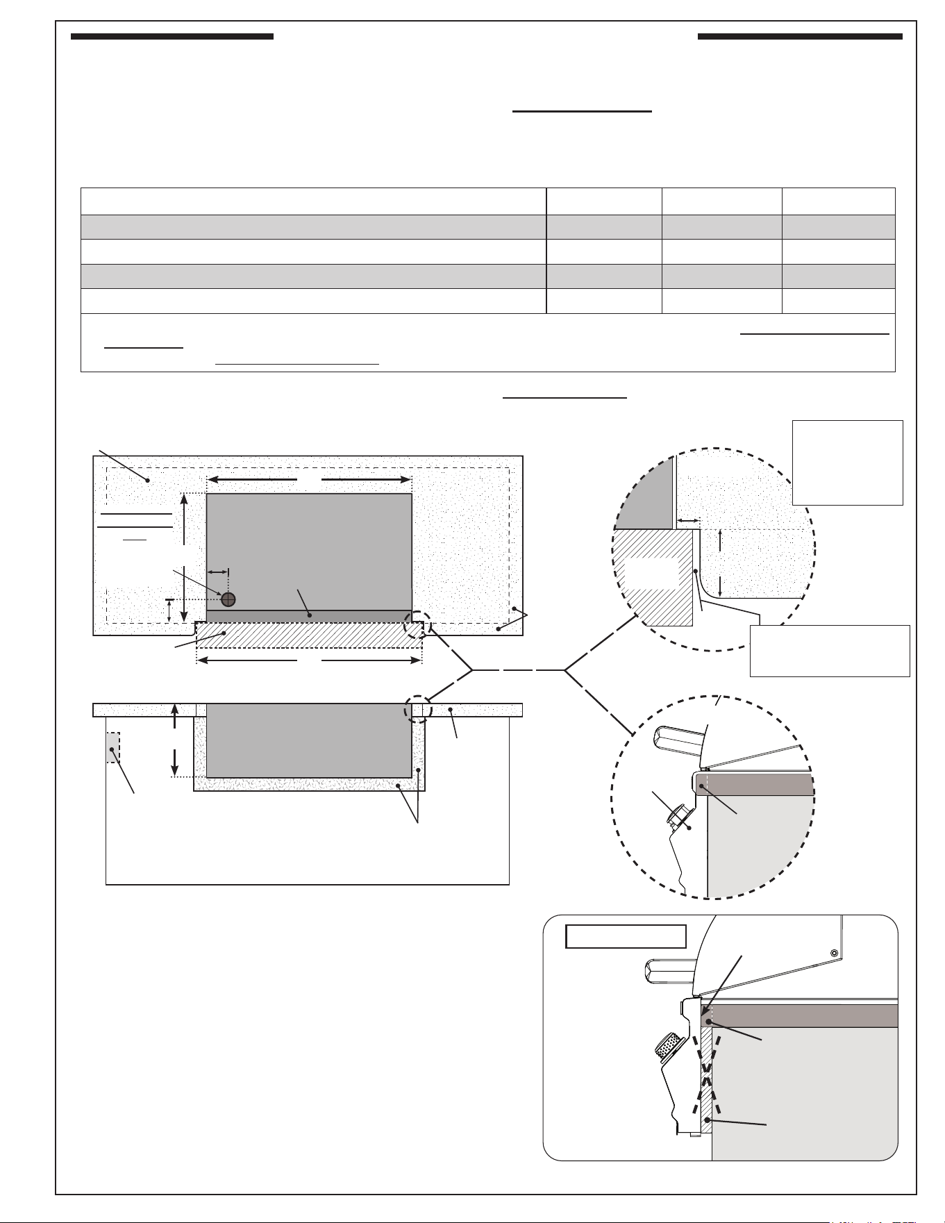
L.P. Cylinder Requirements (if applicable)
When a propane (L.P.) cylinder is installed inside of the
enclosure, the additional guidelines below MUST be
followed. FAILURE TO DO SO MAY CAUSE DAMAGE
TO YOUR UNIT AND/OR PERSONAL INJURY. Refer
to Fig. 14-1 and 14-2.
• Only a C.S.A. listed stainless-steel ex connector
must be connected to the unit.
• The regulator/hose assembly coming from the
cylinder must only be connected to the above
mentioned ex connector. A
1
/2" male-to-male are
adapter will be required (not included). DO NOT
connect the regulator/hose assembly directly to
the unit.
• A non-combustible heat shield must be installed to
protect the regulator/hose assembly and cylinder
valve.
• The cylinder must be properly secured, and rest at
least 2" above the ground.
• An additional vent opening is recommended in
the access door near the cylinder and at the gas
connection level (minimum 10 sq. in. of free area).
• The pressure relief valve on the cylinder must
be pointed toward the vent opening for vapour
withdrawal.
An "access door with tank tray and louvers" is
available. It includes a heat shield that rests directly
above the L.P. cylinder, a tray, a retention device, and
louvers to meet the cylinder install requirements. The
door is shown in Fig. 14-3. Contact your dealer for
ordering information.
Fig. 14-2 Additional vent opening for L.P. cylinder
L.P.
cylinder
Access
door
(Design may vary)
• at cylinder gas
connection level
• min. 10 sq. in. free
area
• point pressure
relief valve (on
cylinder) toward
vent opening
Additional
ventilation
opening
Fig. 14-3 Optional door w/ tank tray & louvers
Cylinder & regulator/hose assembly
protected by heat shield
Additional adapters may be required
for your setup (not included)
Equipped with
adapter for hose
assembly.
Flex connector
not included.
RHP DOOR MEETS ALL REQUIREMENTS ABOVE
Louvers
Tray (w/ retention device)
3" min.
Grill
C.S.A. listed
stainless-steel
ex connector
Non-combustible
heat shield
Regulator/
hose
assembly
2" min.
from ground
Fig. 14-1 L.P cylinder orientation (if applicable)
1
/2" male-to-male
are adapter
(not included)
L.P. cylinder
Cylinder MUST
be secured
(design may vary)
(L.P. Cylinder
setups only)
ENCLOSURE REQUIREMENTS (Cont.)
15
CUTOUT DIMENSIONS
Important: These cutout dimensions below are for non-combustible enclosures. If installing this
grill in a combustible enclosure, the correct insulating liner must be used (and the cutout
dimensions will dier). See Table 3. Refer to the instructions supplied with the liner for the
correct cutout dimensions.
COUNTERTOP OVERHANG
The control panel is designed to sit ush against the enclosure
front wall. If the countertop extends beyond the front wall,
creating a countertop overhang, it must be cut ush with the
front wall for the width of the control panel or a gap will be
created exposing the forward portions of the left and right
side grill re walls. See illustrations in Fig. 15-1 above for the
correct setup, and Fig. 15-2 for an incorrect setup.
Table 1 - Cutout Dimensions (for non-combustible enclosures)
GAP CREATED
Countertop
overhang
Control panel
stops here
INCORRECT
TOP VIEW
Countertop
Lower
support
Countertop
overhang
Control panel
NON-COMBUSTIBLE
GRILL ENCLOSURE
CUTOUT DIMENSIONS
FRONT VIEW
B
C
D
See next page
for substrate
considerations
Countertop
overhang
X
TOP VIEW
SIDE VIEW
Countertop
overhang
(Control
panel)
(Countertop)
Y
1
/
4
"
Clearance
(Overhang)
X= (D-B)÷2
Y= Total
Countertop
Overhang
A
Control
panel
Check clearance for
control panel removal
2
3
/4"
4"
Fig. 15-2
Fig. 15-1 Cutout Dimensions Detail
If a solid area
exists beneath
unit:
1
1
/2" ø or 1
1
/2"
square hole for
gas supply
Description (non-combustible cutouts) C430i C540i C650i
A Countertop to unit bottom cutout 11
1
/2" 11
1
/2" 11
1
/2"
B Side to side non-combustible cutout 25
1
/2" 32" 37
3
/4"
C Front to back non-combustible cutout * 19
1
/2" 19
1
/2" 19
1
/2"
D Control panel width non-combustible cutout † 26
1
/2" 33" 38
3
/4"
*
Includes any substrate at front wall of enclosure (in the area the rear of the control panel is to sit ush against). See SUBSTRATE section
on next page.
†
Only applicable for non-combustible enclosures that have countertops with an overhang (see illustration and section below).
Description (non-combustible cutouts) CM430i CM540i CM650i
A Countertop to unit bottom cutout 11
1
/2" 11
1
/2" 11
1
/2"
B Side to side non-combustible cutout 25
1
/2" 32" 37
3
/4"
C Front to back non-combustible cutout * 19
1
/2" 19
1
/2" 19
1
/2"
D Control panel width non-combustible cutout † 26
1
/2" 33" 38
3
/4"
*
Includes any substrate at front wall of enclosure (in the area the rear of the control panel is to sit ush against). See SUBSTRATE section
on next page.
†
Only applicable for non-combustible enclosures that have countertops with an overhang (see illustration and section below).
Timer Box
Reference the instruction manual included with your timer box
for all cutout / installation details.
Timer
box
cutout
ENCLOSURE REQUIREMENTS (Cont.)
16
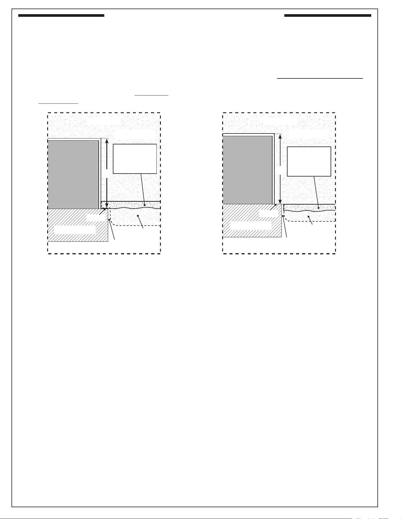
SUBSTRATE
When adding any substrate to the enclosure front wall (including tiles, stone, etc.), consider the following:
Substrate Behind Control Panel
Substrate Alongside Control Panel
C
C
Flush
(Control panel)
(Countertop)
(Countertop)
(Control panel)
Substrate
(includes tiles,
etc. at front of
enclosure)
Countertop
overhang
(if applicable)
Flush
Grill
Grill
Substrate
(includes tiles,
etc. at front of
enclosure)
1
/
4
"
Clearance
Any additional substrate alongside the control panel
does not need to be considered in Dim. C (see previous
page), however a
1
/4" clearance on each side (same as
overhang) and below is required.
Substrate
+
countertop "front to back" cutout
must equate to Dim. C (see previous page)
when the substrate sits ush behind the
control panel.
Countertop
overhang
(if applicable)
1
/
4
"
Clearance
TOP VIEW TOP VIEW
Fig. 16-1 Fig. 16-2
ENCLOSURE REQUIREMENTS (Cont.)ENCLOSURE REQUIREMENTS (Cont.)
17
Installation must be performed by a qualied professional
service technician.
This unit is designed for outdoor use only. DO NOT use this
unit inside a building, garage, or enclosed area. DO NOT install
this unit in or on a recreational vehicle or boat.
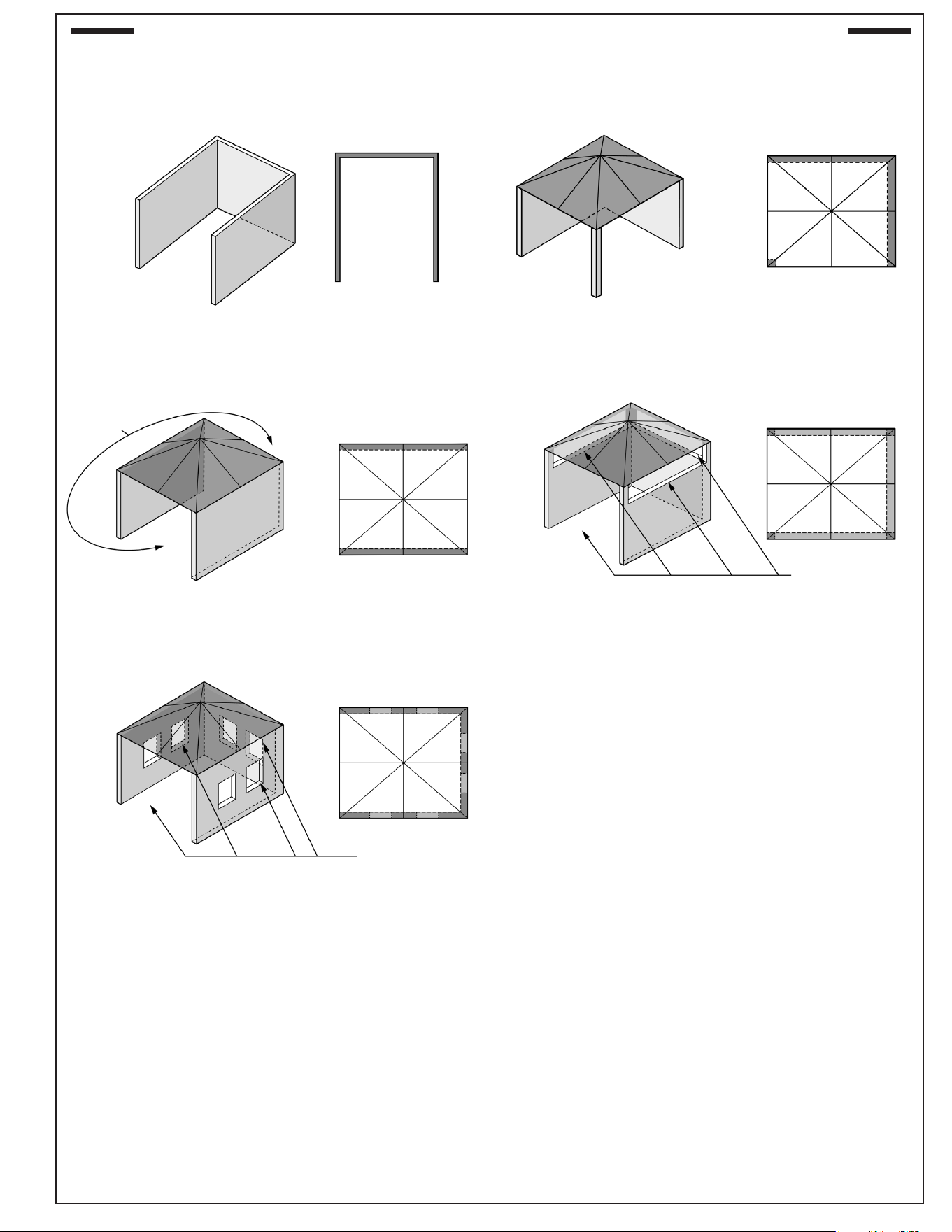
Any constructed outdoor area in which the appliance is
used shall comply with one of the following:
• An outdoor area with walls on three sides, and no
overhead cover
• Within a partial outdoor area that includes an overhead
cover and no more than two walls. The sidewalls may
be parallel, as in a breezeway, or at right angles to each
other
• Within a partial outdoor area that includes an overhead
cover with walls on three sides, and at least 30% or more
of the horizontal periphery of the enclosure that is open
and unrestricted
Note: All openings must be permanently open.
Note: Sliding doors, garage doors, windows, or screened
openings are not considered as permanent openings.
Refer to DIAGRAMMATICAL REPRESENTATIONS OF
OUTDOOR AREAS section.
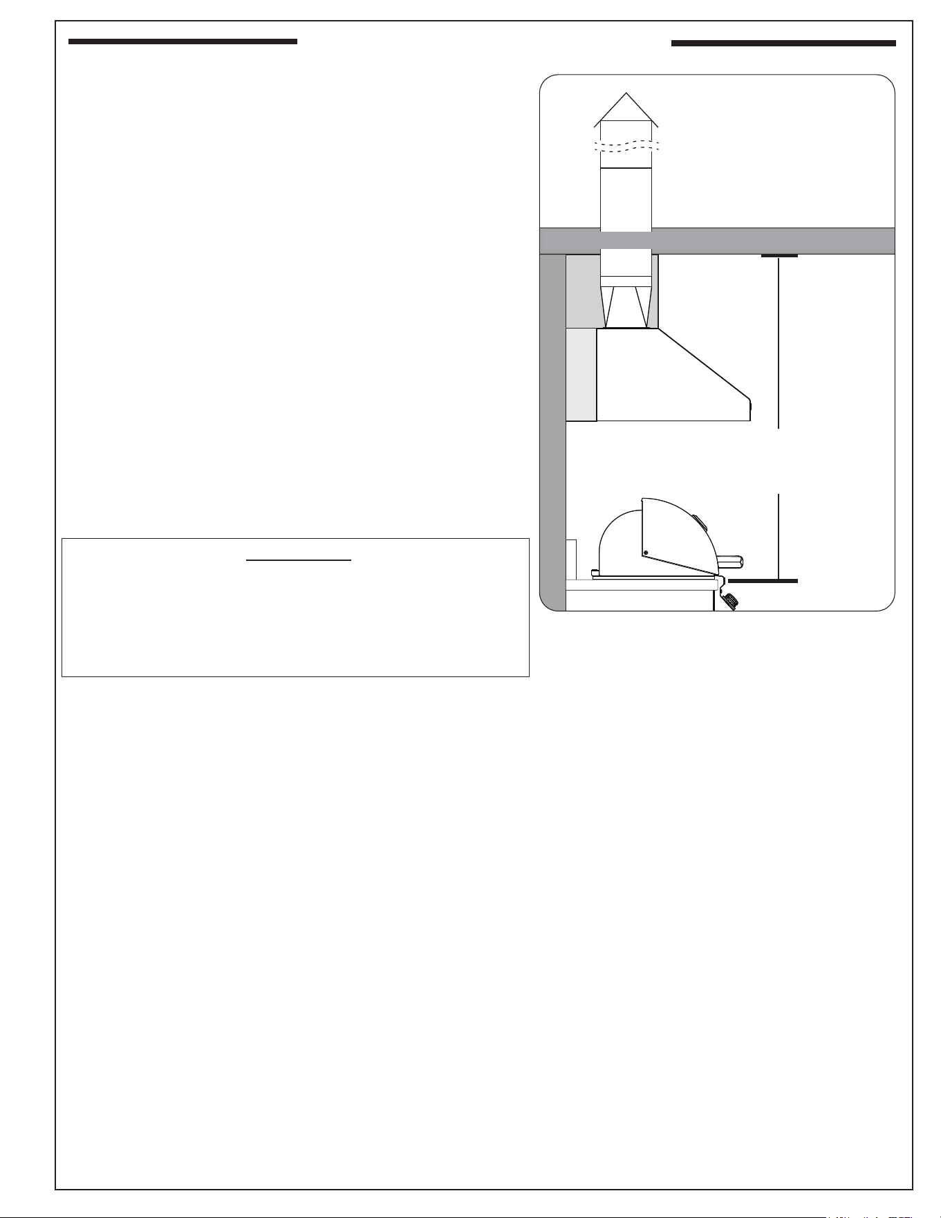
EXHAUST HOOD
IMPORTANT:
DO NOT use this appliance under combustible overhead
construction unless installed in conjunction with a suitable
UL 710 or ULC S646 approved heavy duty vent hood only.
The vent hood must be placed in operation during operation
of the appliance.
When installed under overhead non-combustible construction,
an exhaust hood is highly recommended; see exhaust hood
information below and Fig. 17-1.
When using an exhaust hood, the area above the cooking
surface of the grill must be covered with a hood larger than
the cooking area of the grill and with a minimum of 1200 CFM
(cubic feet per minute) rated exhaust fan for proper outdoor
application.
Fire Magic vent hoods, spacers, and duct covers are available.
See Table 3. Contact your local dealer.
Clearances
A minimum 5 foot clearance is required between the
countertop and the overhead construction. (No combustible
materials are allowed within this area.)
Fig. 17-1 Overhead requirements
N
O
N
C
O
M
B
U
S
T
I
B
L
E
R
E
A
R
W
A
L
L
EXHAUST HOOD
(Fire Magic
setup shown)
S
O
F
F
I
T
S
P
A
C
E
R
Min. 5'
from countertop to
non-combustible overhead
construction
NON-COMBUSTIBLE OVERHEAD CONSTRUCTION
INSTALLATION REQUIREMENTS
18
CLEARANCES
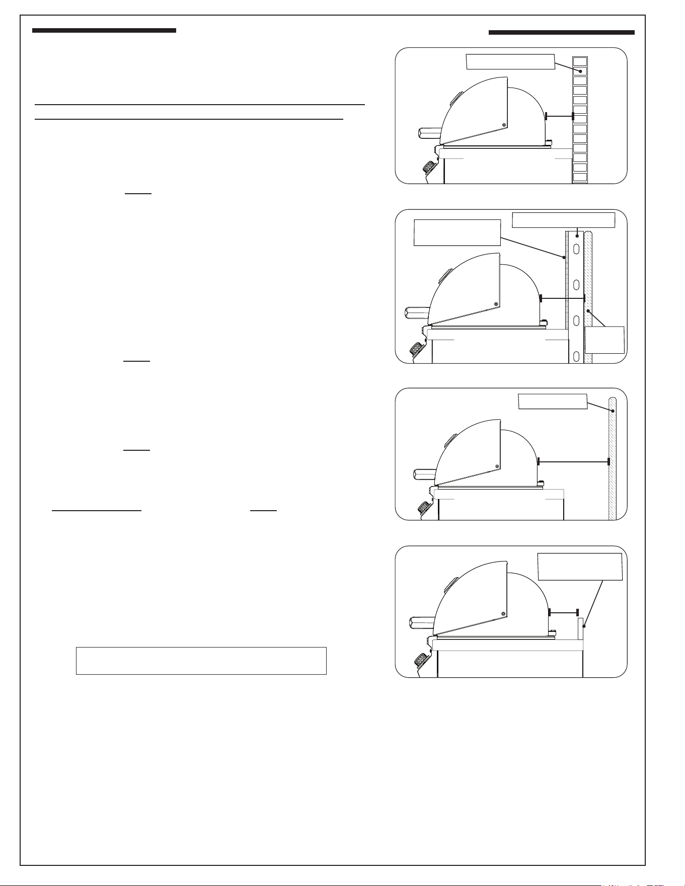
Rear Wall
For the minimum clearances between the unit and rear walls,
your setup must fall within one (or more) of the following:
A. Clearance between unit and strictly non-combustible
rear wall
(i.e. brick wall, see Fig. 18-1)
• The unit must have a minimum clearance of 4" from
the non-combustible rear wall.
(To allow for proper ventilation and prevent dangerous
overheating.)
B. Clearance between unit and a protected combustible
rear wall
(i.e. a non-combustible wall in front of a combustible wall
to serve as a barrier. This can be accomplished by brick,
or a metal stud nished with non-combustible substrate,
see Fig. 18-2)
• The unit must have a minimum clearance of 14" from
the protected combustible rear wall.
(The 4" non-combustible material plus an additional 10"
clearance between the unit and protected rear wall.)
C. Clearance between unit and combustible rear wall
• The unit must have a minimum clearance of 18" from
the combustible rear wall (see Fig. 18-3).
Backsplash (if applicable)
If a non-combustible backsplash exists, it must have a minimum
of a 4" clearance from the rear of the unit (to allow for proper
ventilation and prevent dangerous overheating). See Fig. 18-4.
Important: This 4" backsplash clearance must rst be met
prior to any non-combustible walls beginning
behind it.
Fig. 18-1 Clearance 'A' Diagram
Fig. 18-2 Clearance 'B' Diagram
Fig. 18-3 Clearance 'C' Diagram
Non-combustible
Min.
4"
Min.
14"
Non-combustible
substrate
Non-combustible 4"
Combustible
Min.
18"
Fig. 18-4 Backsplash clearance
Non-combustible
Backsplash
Min.
4"
Com-
bustible
(Clearance required
for rear wall)
(Clearance required
for rear wall)
(Clearance required
for rear wall)
Clearances continued on the following page
INSTALLATION REQUIREMENTS (Cont.)
19
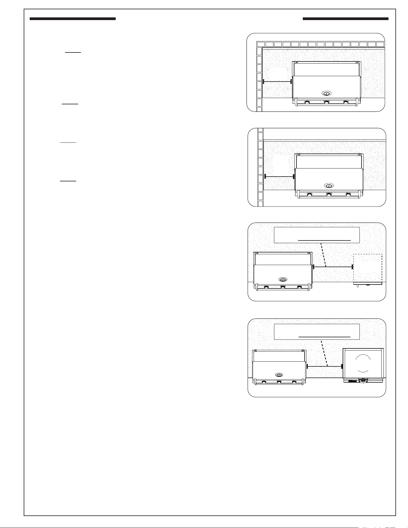
Corner Wall (if applicable)
The unit must have a minimum clearance of 24" from any
corner walls (to account for variables in airow that could aect
performance). See Fig. 19-1.
Side Wall (if applicable)
The unit must have a minimum clearance of 18" from any side
walls. See Fig. 19-2.
Cooling Appliance (if applicable)
The unit must have a minimum clearance of 14" from any cooling
appliances such as refrigerators, kegerators, etc. See Fig. 19-3.
Heating Appliance (if applicable)
The unit must have a minimum clearance of 12" from any heating
appliances such as pizza oven, griddle, etc. See Fig. 19-4.
Fig. 19-1 Corner wall clearance
Min.
24"
Fig. 19-2 Side wall clearance
Min.
18"
Fig. 19-4 Clearance to heating appliances
Fig. 19-3 Clearance to cooling appliances
KEEP MINIMUM DISTANCE OF 14"
FROM COOLING APPLIANCES
(Refrigerator
shown here)
KEEP MINIMUM DISTANCE OF 12"
FROM HEATING APPLIANCES
(Pizza Oven
shown here)
INSTALLATION REQUIREMENTS (Cont.)
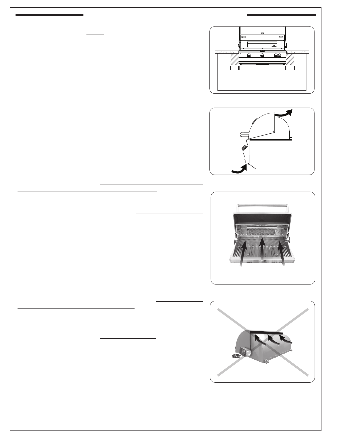
20
CONTROL PANEL CLEARANCES
• The control panel MUST have a minimum side clearance of 6"
from any obstructions/side walls. See Fig. 20-1.
(To allow for control panel removal.)
• The control panel MUST remain removable for servicing
(see CONTROL PANEL REMOVAL section). Any adjacent
countertops must not obstruct the panel from being removed.
COMBUSTION AIR AND COOLING AIRFLOW
Proper airow (front-to-back, Fig. 20-2) MUST be maintained for the
unit to perform as it was designed. If airow is blocked, overheating
and poor combustion will result. Do not block the front air inlet along
the bottom of the control panel.
CAUTION: Wind blowing into or across the rear oven lid vent (Fig.
20-4) can cause poor performance and/or dangerous overheating.
Install the grill so that the prevailing wind blows toward the front of
the grill (Fig. 20-3). A wind deector is included (pre-installed) to
assist in proper airow during windy conditions. See Fig. 20-2.
GAS-SUPPLY PLUMBING REQUIREMENTS
The gas supply is to be routed into the enclosure, near the unit. Your
individual installation may vary. Observe the National Fuel Gas Code
and all local codes. Leak test at all connections.
The gas supply must be sized to provide minimum inlet pressure
at the maximum ow rate (BTU/hr). Undue pressure loss will occur
if the pipe is too small, or the run is too long. Gas supply pipe must be
½" minimum interior diameter. If the gas line is longer than 20', a larger
diameter line may be necessary. Refer to the NFPA 54 guidelines for
further details.
DO NOT use a rubber hose within the enclosure.
A C.S.A. approved stainless steel ex connector is included and pre-
installed to the valve manifold, and routes to the gas supply. A are-
to-NPT adapter is provided for
1
/2" pipe. The use of any rigid pipe,
semi-rigid tubing, and connectors must comply with the Standard for
Connectors for Outdoor Gas Appliances and Manufactured Homes,
ANSI Z21. 75 (CSA 6.27).
Use a pipe joint compound resistant to all gasses on all NPT pipe
ttings. Make sure to tighten every tting securely. Do not use pipe
joint compound to connect are ttings.
Important: A shut-o valve (not included) in the gas supply
line is required. It must be installed within 6 feet of the unit and
must be easily accessible. Use a pipe joint compound resistant to all
gasses on all NPT pipe ttings except are ttings. Refer to NFPA
54 guidelines for further details.
GAS SUPPLY INLET PRESSURES:
For natural gas - normal 7" water column (w.c.), minimum 5", maximum
10
1
/
2
". For propane gas - normal 11" w.c., minimum 10", maximum
13".
Note: An additional regulator may be needed to meet these
requirements.
Note: A sediment trap in the gas supply line is recommended where
applicable. It should be installed downstream of the shut-
o valve as close to the unit as possible. Refer to NFPA 54
guidelines for further details.
CORRECT
PLACE GRILL SO PREVAILING
WIND BLOWS TOWARD FRONT
OF GRILL
Fig. 20-3 Airow direction - CORRECT
Fig. 20-2 Airow diagram
YOU MUST PROTECT
REAR OVEN VENT FROM
PREVAILING WIND
Rear oven lid vent
INCORRECT
Fig. 20-4 Airow direction - INCORRECT
Fig. 20-1 Control panel clearances
Min.
6"
Min.
6"
Fig. 20-2 Airow diagram
Front air inlet (do not block)
INSTALLATION REQUIREMENTS (Cont.)
21
The following gures are diagrammatical representations of outdoor areas, as dened in Clause 4.25.3. See
INSTALLATION REQUIREMENTS section.
Fig. 21-1 Outdoor area - Example 1
Fig. 21-2 Outdoor area - Example 2
Fig. 21-3 Outdoor area - Example 3 Fig. 21-4 Outdoor area - Example 4
Fig. 21-5 Outdoor area - Example 5
Both ends open
30% or more of the horizontal
periphery of the enclosure is
open and unrestricted
30% or more of the horizontal
periphery of the enclosure is
open and unrestricted
DIAGRAMMATICAL REPRESENTATIONS OF OUTDOOR AREAS
22
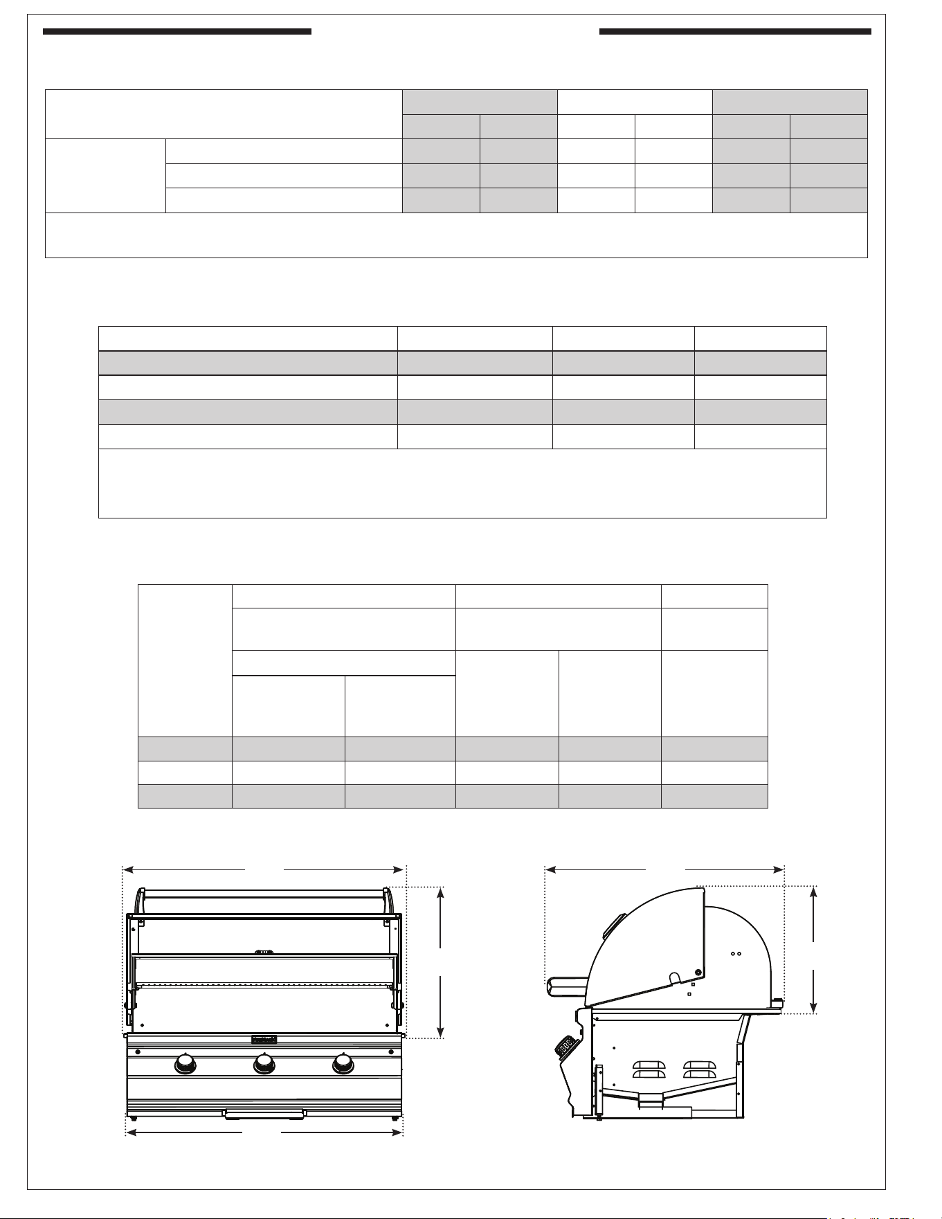
MODEL SPECIFICATIONS
E
B
A
C
D
Fig. 22-1
Table 4 - Grill Dimensions
Model
Height Width Depth
(Top to bottom) (Left to right)
(Front to
back)
Bottom of hanger to top
Maximum
width
(C)
Control
panel
width
(D)
Maximum
depth
(E)
With oven lid
OPEN
(A)
With oven lid
CLOSED
(B)
CM430i 20
3
/4" 13
5
/8" 27
5
/8" 26" 25
3
/4"
CM540i 20
3
/4" 13
5
/8" 34
1
/8" 32
1
/2" 25
3
/4"
CM650i 20
3
/4" 13
5
/8" 39
3
/4" 38
1
/4" 25
3
/4"
(CM540i shown)
CM430i CM540i CM650i
Nat. L.P. Nat. L.P. Nat. L.P.
Main burner
Quantity
2 2 3 3 3 3
Nat./L.P. orice drill size
#41 #54 #43 #55 #41 #54
Nat./L.P. air shutter opening *
3
/8"
5
/16"
3
/8"
5
/16"
3
/8"
5
/16"
* These are air shutter factory settings. These settings may require adjustment due to gas conversion, altitude, or other local conditions.
See AIR SHUTTER ADJUSTMENT / BURNER FLAME INSPECTION section.
Table 2 - Product Specications
CM430i CM540i
CM650i
Fire Magic insulating liner model # *
†
23130-52 23150-52 3177-52
Vent hood model # *
ŧ
36-VH-7
ŧ
36-VH-7
ŧ
42-VH-7
ŧ
Vent hood spacer model # *
ŧ
36-VH-7-02
ŧ
36-VH-7-02
ŧ
42-VH-7-02
ŧ
Vent hood duct cover model # *
ŧ
36-VH-7-DC
ŧ
36-VH-7-DC
ŧ
42-VH-7-DC
ŧ
*
If applicable, not included
† If installing this grill in a combustible enclosure, the correct insulating liner must be used. Consult liner instructions for
counter cutout dimensions and installation.
ŧ This model meets the minimum size requirements; larger models are also acceptable.
Table 3 - Grill Supporting Products
23
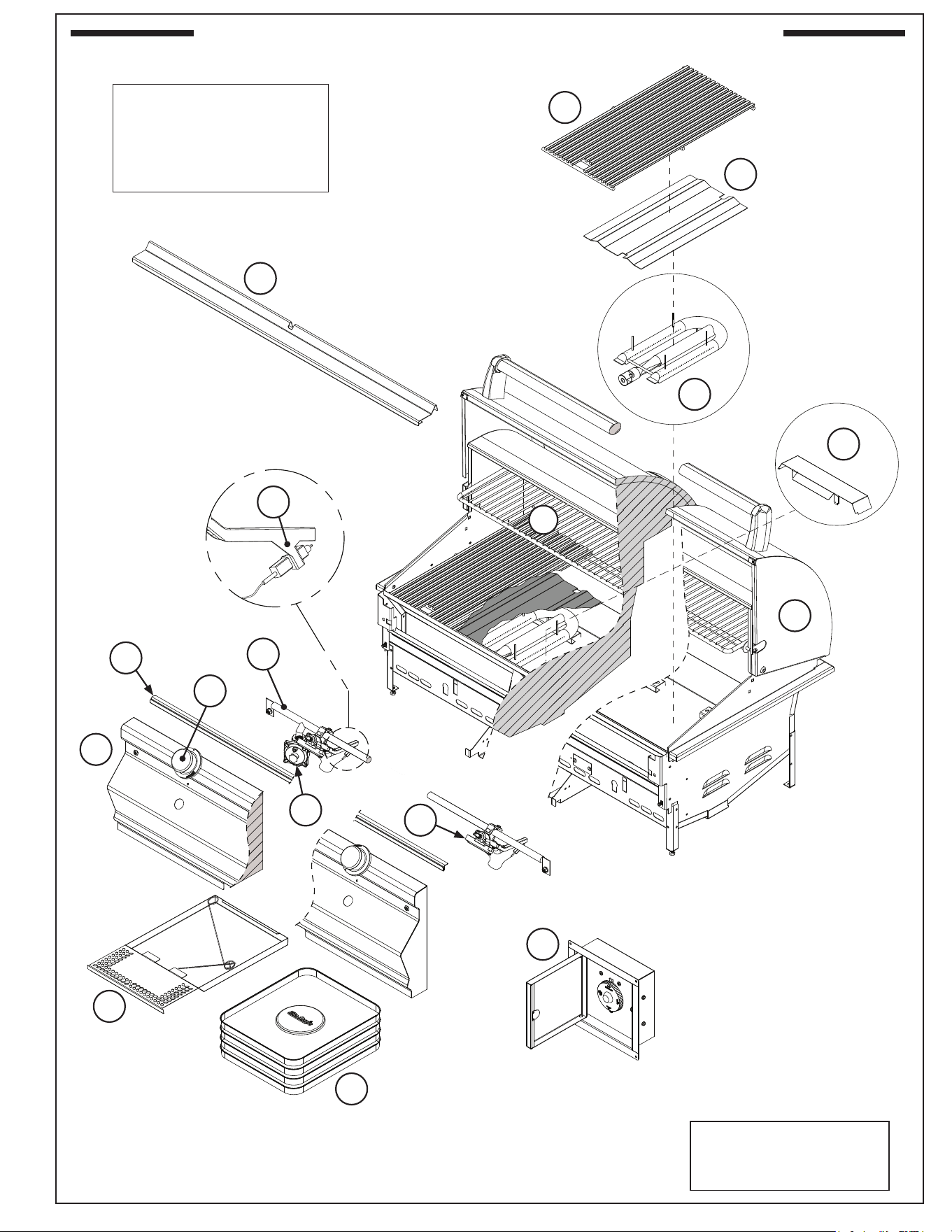
1
2
3
7
9
13
6
4
14
11
20
19
16
15
8
10
21
To order replacement
parts, contact your local
Fire Magic
®
dealer.
CHOICE MULTI-USER GRILL REPLACEMENT PARTS LIST
IMPORTANT
Remove all packing
material and discard prior
to lighting.
24
CM430i CM540i CM650i
Item Description Part No. Qty. Part No. Qty. Part No. Qty.
1. Stainless cooking grid (set of 2 or 3) 3542-DS-2 1 23543-DS-3 1 3542-DS-3 1
2. Flavor grid (set of 2 or 3) 3063-S-2 1 3064-S-3 1 3065-S-3 1
3. Main burner 3042-60 2 3042-60 3 3042-60 3
4. Oven lid w/ oven thermometer 23729-58 1 23733-58 1 23734-50 1
5. Oven lid spring kit * 23729-72 1 23729-72 1 23729-72 1
6. Warming rack 3672S-B 1 3673S-B 1 3675S-B 1
7. Convertible regulator PR-4 1 PR-4 1 PR-4 1
8. Valve manifold 24131-12 1 24171-12 1 24181-12 1
9. Control panel assembly 24131-02 1 24171-02 1 24181-01 1
10. Cooking grid locking channel 24131-03 1 24171-03 1 24181-02 1
11. Control knob w/ locking screw 3026CM 2 3026CM 3 3026CM 3
12. Oven lid thermometer w/ bezel * 23307 1 23307 1 23307 1
13. Drip tray with match holder 3093 1 3093 1 3093 1
14. Drip tray liner (set of 4) 3557 1 3557 1 3557 1
15. Main burner igniter assy only 3199-50 2 3199-50 3 3199-50 3
16. Main burner valve w/ orices & igniter 3025 2 3025 3 3025 3
17. Natural gas orice(s) * 3031-41-2 1 3031-43-3 1 3031-41-3 1
18. Propane gas orice(s) * 3031-54-2 1 3031-55-3 1 3031-54-3 1
19. Air bae 24194-40 1 24194-40 1 24194-40 1
20. Wind deector 23729-19 1 23733-19 1 23745-20 1
21. Timer box 5521-11T 1 5521-11T 1 5521-11T 1
* Not shown
CHOICE MULTI-USER GRILL REPLACEMENT PARTS LIST (Cont.)
25
INSTALLATION
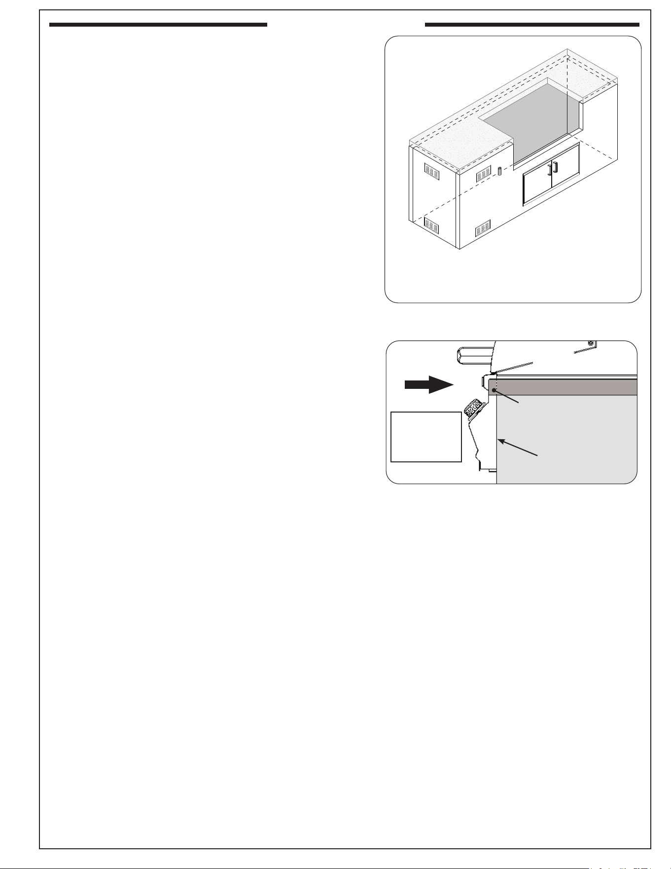
INSTALLATION
Ensure control
panel is ush
Countertop
Overhang
Fig. 25-2 Slide in unit (ensure ush)
SLIDE IN
(be careful
when inserting
ex hose)
It is not required to remove the control panel or knobs to
install this unit.
DO NOT lift the unit from the control panel when installing.
BUILD / CONSTRUCT ENCLOSURE
GFRC islands are available (for select models). They
accommodate your grill and side cooker/accessories. Build the
enclosure per the instructions supplied with the unit.
Alternatively, a custom-built enclosure can be constructed.
Construct the enclosure according to your individual install
preference, while following the guidelines found in the
ENCLOSURE REQUIREMENTS and INSTALLATION
REQUIREMENTS sections.
• Construct the enclosure in an appropriate location
(ensure all requirements of this manual and all local
codes are met when determining location).
• Follow all information regarding enclosure
parameters, ventilation, drainage, cylinder
requirements, cutout dimensions, and clearances
listed in the ENCLOSURE REQUIREMENTS and
INSTALLATION REQUIREMENTS sections. Failure
to do so will prevent proper operation and can cause
property damage or personal injury.
INSTALL TIMER BOX
Reference the instruction manual included with the timer box
for all details.
INSTALL INSULATING LINER (if applicable)
If installing your unit in a combustible enclosure, the correct
insulating liner must be used. Refer to the instructions supplied
with the liner for installation.
SLIDE UNIT INTO ENCLOSURE CUTOUT
CAUTION: THE GRILL IS HEAVY AND REQUIRES TWO
OR MORE PEOPLE FOR SAFE HANDLING.
1. Carefully slide the unit into the enclosure cutout, being
sure to simultaneously route the ex connector down
into the enclosure. (If using an insulating liner or if the
enclosure has a solid area beneath the unit, route the
gas connections through the hole/cutout found in the
enclosure/insulating liner. For details on the hole/cutout,
see the illustration under CUTOUT DIMENSIONS in the
ENCLOSURE REQUIREMENTS section or refer to the
instructions supplied with the liner.)
• Ensure the gas connections are clear, undamaged,
and completely inserted into the opening, and that
the unit is correctly inserted without any obstructions
between it and the countertop.
• Ensure the unit fully slides in so that the control panel
sits ush against the enclosure front wall. See the
COUNTERTOP OVERHANG section in ENCLOSURE
REQUIREMENTS for details.
• If installing on a countertop with an irregular/textured
surface, a bead of silicone sealer rated for 400° F
(204° C) or higher is recommended to protect from the
elements.
(Grill)
Fig. 25-1 Enclosure construction overview
(if applicable)
• Not to scale
• Example shown, design and location of enclosure and its
items may vary
• See ENCLOSURE REQUIREMENTS section for details
26
INSTALLATION (Cont.)
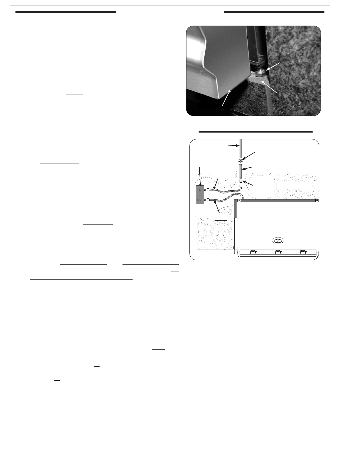
Bottom of control panel
Lower support
Fig. 26-1 Front support adjustment bolts
Front
support
adjustment
bolt
2. Rotate the front support adjustment bolts (up or down)
until the grill hanger rests ush on the countertop,
AND, the adjustment bolts are touching the supporting
structure found at the bottom of the cutout (lower
support). Use a
7
/16" open-end wrench as needed.
See Fig. 26-1.
• The grill should not solely rest on just the hanger or
just the adjustment bolts.
• The bolts MUST be used to provide support to the
hangers.
CONNECT GAS SUPPLY
To Connect To Propane Cylinder:
Read the safety warnings and follow the instructions in the
section SAFE USE AND MAINTENANCE OF PROPANE
GAS CYLINDERS.
Note: When a propane cylinder is installed inside of
the enclosure, the guidelines found in the GRILL
ENCLOSURE / VENTILATION REQUIREMENTS
section MUST be followed.
To Connect To Natural Or Household Propane Gas
Supply:
CAUTION: Use only C.S.A. listed stainless-steel flex
connectors within the enclosure.
WARNING
A rubber or plastic connector will rupture or leak,
resulting in an explosion or serious injury if used inside
the appliance enclosure.
• Before connecting the gas supply to your appliance,
pressures MUST be tested and MUST NOT exceed
10.5" w.c. for Nat. gas and 13" w.c. for L.P. gas. An
additional regulator may be required.
• Refer to the GAS SUPPLY PLUMBING
REQUIREMENTS section for all details on the gas
supply and its setup.
1. Turn OFF the gas supply at the source.
2. Run the attached ex connector (coming from the grill)
to the timer box area.
3. Using two wrenches, connect the ex connector coming
from the grill to the
1
/2" are adapter labeled OUT. See
Fig. 26-2. Ensure the connection is tightened securely.
4. Connect gas source to IN: Using two wrenches, connect
a ex connector (not included) to the
1
/2" are adapter
labeled IN. See Fig. 26-2. Ensure the connection is
tightened securely.
5. Route the ex connector coming from the timer box to the
gas supply stub (see Fig. 26-2).
Fig. 26-2 Household LP & Nat. gas diagram
Gas supply (NPT)
OFF
Gas supply
Shut-o valve (shown in-
line) must be within 6 feet
of the unit and must be
easily accessible
(Countertop)
Timer box
Flare-
to-NPT
adapter
Flex connector
(included)
Flex connector
(not included)
27
INSTALLATION (Cont.)
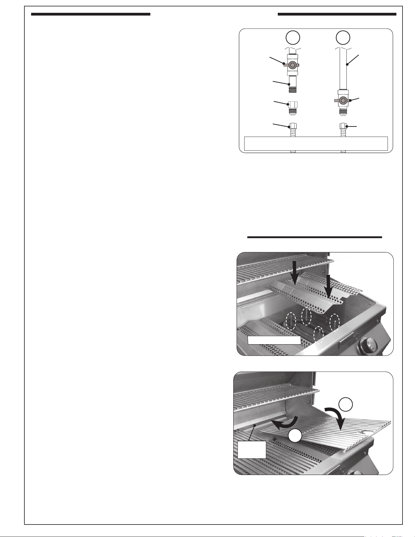
6. A shut-o valve is required within 6 feet of the unit and
must be easily accessible.
If shut-o valve is installed in-line:
• Install the supplied are-to-NPT adapter to the gas
supply (NPT) using a pipe joint compound resistant to
all gasses (see Fig. 27-1, A). Tighten securely.
• Connect the ex connector to the adapter (see Fig.
27-1, A). Tighten securely.
If shut-o valve is connected to end of gas supply
stub:
• Connect the ex connector to the shut-o valve (are)
(see Fig. 27-1, B). Tighten securely.
LEAK TEST
Turn all burner valves to the OFF position. Turn on the gas
supply, and test at all connections for leaks using a soapy
water solution. If bubbles appear, a leak is present. Turn o the
gas and tighten at all connections. Repeat until no leaks are
present. If a leak persists, turn o the gas supply and contact
the local gas company or dealer. NEVER USE A FLAME TO
CHECK FOR LEAKS.
Once the leak test is complete, turn o the gas supply
and proceed.
INSTALL FLAVOR GRIDS
Place the avor grids directly onto the studs on the burners
(see Fig. 27-2). For 540i and 650i models, the slightly
larger grids are designed to be placed over the outside
burners, and the slightly smaller grid over the inner
burner. The avor grids allow heat from the burners to be
evenly distributed throughout the cooking area.
INSTALL COOKING GRIDS
Note: Wear heat-resistant gloves if necessary.
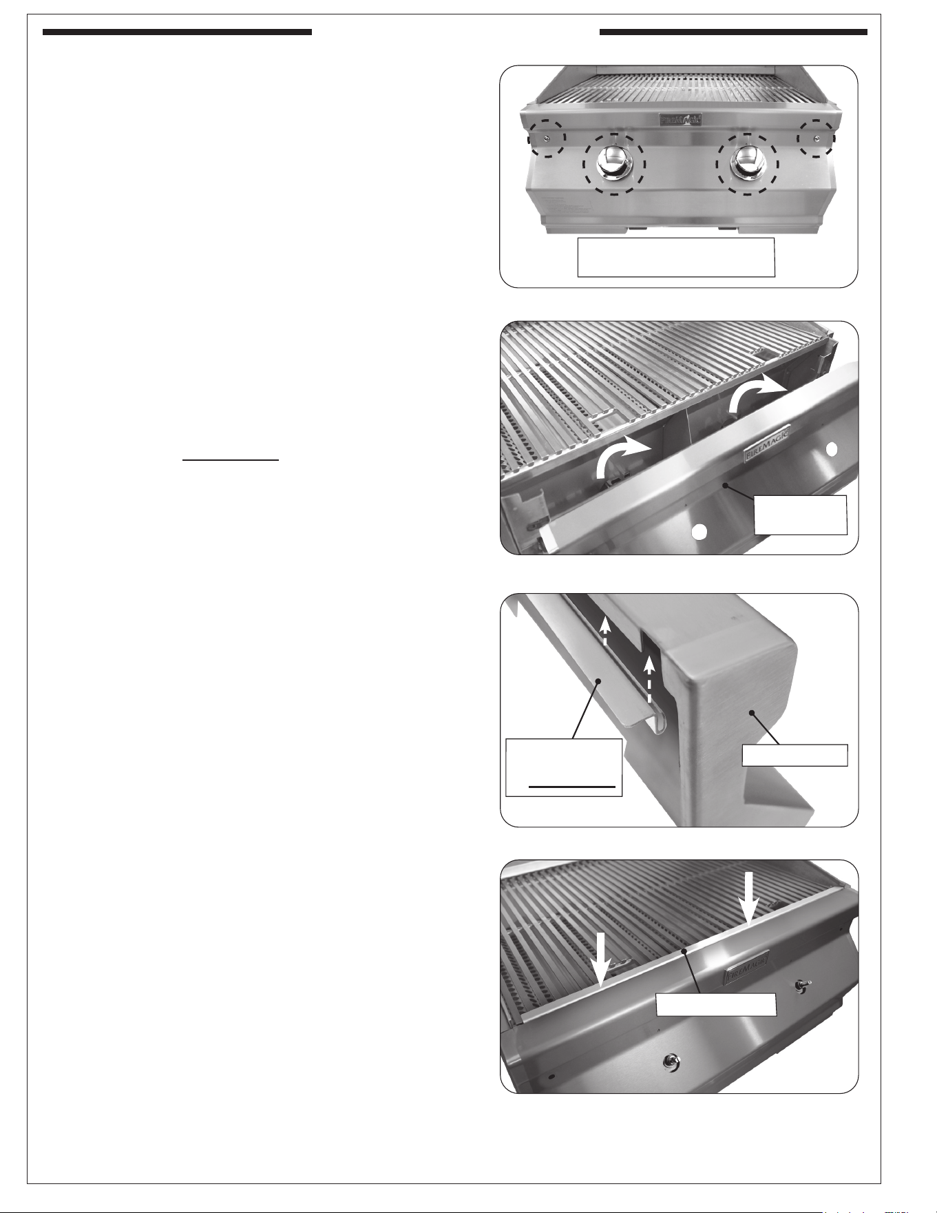
1. Carefully place the rear of a cooking grid between the
locking ridge of the rear wall (see Fig. 27-3, A). Then,
carefully place the front of the cooking grid onto the front
grid rest of the grill (see Fig. 27-3, B).
2. Repeat for the other grids.
Fig. 27-1 Connecting to a gas line
Gas supply
(NPT)
Flex
connector
(from grill)
Flare-to-NPT
shut-o
valve*
(end of gas
supply)
NPT-to-NPT
shut-o
valve*
(in-line)
Gas supply
(NPT)
Flare-to-NPT
adapter
Flex
connector
(from grill)
* Shut-o valve: required, not included, must be within
6 feet of unit and must be easily accessible.
A B
-OR-
Place onto studs
Fig. 27-2 Install avor grids
Fig. 27-3 Install cooking grids
A
B
Locking
ridge
28
INSTALLATION (Cont.)
SECURE COOKING GRIDS
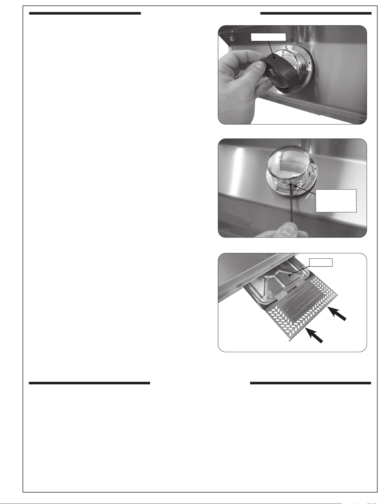
Remove control knobs and control panel
1. Turn the control knobs to the OFF position and turn
o the gas supply to the unit.
2. Pull the control knobs from the stems and set aside
(see Fig. 28-1).
3. Using a Phillips screwdriver, unscrew and remove
the control panel fastener screws and washers
(located on the left and right front face of the control
panel). Retain the screws for later re-installation.
See Fig. 28-1.
4. Carefully remove the control panel by lifting and
pulling the control panel from the frame. Set control
panel aside (see Fig. 28-2).
Install cooking grid locking channel
1. Attach the cooking grid locking channel to the rear
top lip of the control panel (see Fig. 28-3).
2. With the channel attached to the control panel,
carefully reinstall the control panel back onto the
grill. Ensure the locking channel is laying at on the
cooking grids. See Fig. 28-4.
3. Reinstall the two screws to secure the control panel.
4. Insert the control knobs onto the valve stems.
Ensure the control knobs are in the OFF position.
Fig. 28-1 Remove knobs and screws
Fig. 28-2 Remove control panel
Remove
control panel
Fig. 28-3 Attach cooking grid locking channel
Attach locking
channel to rear
of control panel
Fig. 28-4 Install cooking grid with locking channel
Remove control knobs, and
screws and washers
Locking channel
(Control panel)
29
INSTALLATION (Cont.)
LOCK CONTROL KNOBS
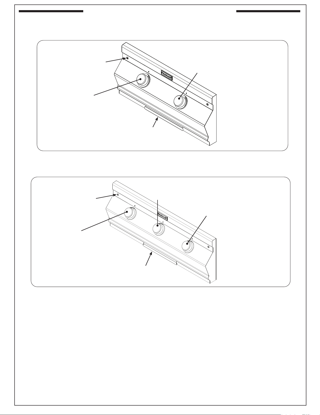
1. Turn the control knobs to the OFF position and
turn o the gas supply to the unit.
2. Remove the rubber grip from the control knob (see
Fig. 29-1).
3. Insert the included .078" (2mm) hex key through
the small hole located on the side of the knob and
fully tighten the screw (see Fig. 29-2).
4. Replace the rubber grip.
5. Repeat this process for the remaining knobs.
INSTALL DRIP TRAY
Your grill includes a pack of four drip tray liners. Place
a liner into the drip tray as shown in Fig. 29-3, and fully
insert the drip tray into the bottom front of the control
panel.
Note: The liner must t under the rear lip and two front
tabs found on the drip tray.
Fig. 29-2 Tighten screw to lock knobs
Fig. 29-3 Install drip tray
Liner
Fig. 29-1 Remove rubber grips
Rubber grip
Tighten screw
(inside hole)
with hex key
After installation, perform an operation test of the grill and its features/accessories. Refer to the following sections
for details.
OPERATION TEST
30
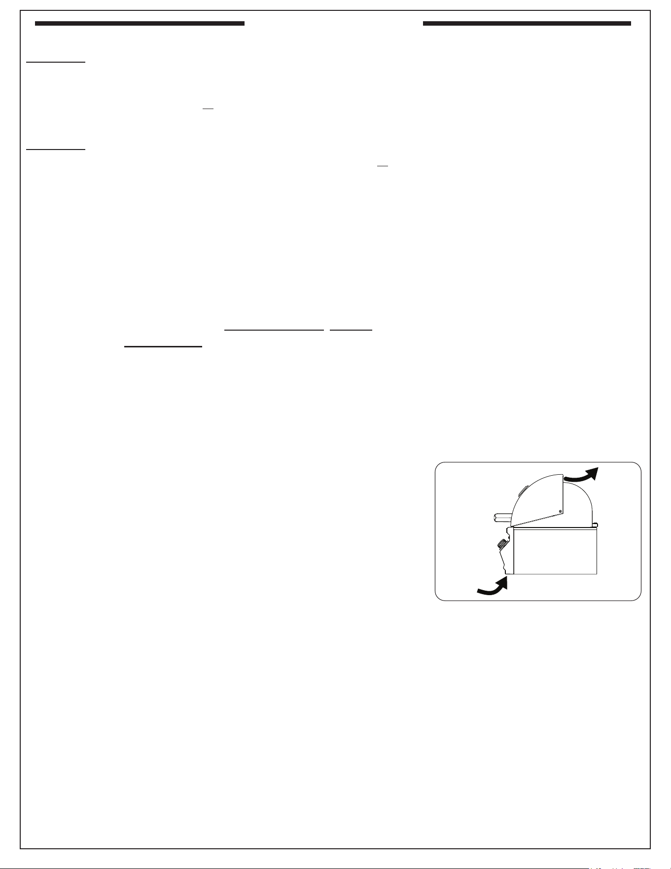
Left
main burner
control knob
Right
main burner
control knob
Center main burner
control knob
Left
main burner
control knob
Right
main burner
control knob
Drip tray
Drip tray
Control panel
screw(s)
Control panel
screw(s)
Fig. 30-1 C430i controls
Fig. 30-2 C540i and C650i controls
Fig. 30-1 CM430i controls
Fig. 30-2 CM540i and CM650i controls
(CM650i model shown)
IDENTIFICATION OF GRILL CONTROLS
USE, CARE, & SERVICE
31
BEFORE INITIAL USE
Ensure that:
• the unit has been properly installed and leak tested by a qualied professional service technician and as instructed in this
manual.
• you have read and understand all of the information in this manual.
BEFORE EACH USE
Ensure that:
• you smell around the appliance area for gas. If you smell gas (and all control knobs are in the OFF position), immediately
shut o the gas supply and contact a qualied professional service technician or the gas supplier for inspection.
• the required vent openings and surrounding area of the enclosure are clear at all times.
• the cooking area and drip tray are clean, and the drip tray is properly installed.
• you inspect all piping and hoses for damage, cuts, wear, and tear. Replace any damaged components prior to use.
OPERATION
• The unit becomes HOT during use. NEVER touch any part of the cooking area or surrounding hot surfaces with
bare hands. Use long-handled insulated BBQ tools and wear an insulated glove / oven mitt.
• Always keep your face and body as far from the unit as possible during use. Avoid wearing loose-tting clothing
as they could ignite.
• This appliance is designed as an attended appliance. DO NOT leave this appliance burning when unattended.
• NEVER cover more than 75% of the cooking surface with griddles, pots or pans to prevent overheating.
• After each use, turn the control knob(s) to the OFF position and turn o the gas supply to the unit.
After reading and understanding all bullets above, follow these steps to light and use your grill:
1. Light the grill per the LIGHTING INSTRUCTIONS section.
2. Turn the control knobs to the HI-LIGHT position, close the hood, and allow the grill to preheat for 15 minutes or until desired
cooking temperature is reached.
3. Place the food on the grill and cook as desired. Monitor the ames and the temperature, and adjust the heat setting if necessary.
4. See the sections below and the following pages for all other information regarding use.
WIND CONSIDERATIONS
Proper airow (front-to-back, Fig. 31-1) MUST be maintained for the unit to perform
as it was designed. See the INSTALLATION REQUIREMENTS section for details.
When using the unit in windy conditions, the wind can disrupt the airow and cause
overheating. To prevent overheating during windy conditions, do not leave the hood
closed with the burners on high for more than 15 minutes.
AFTER EACH USE
1. Operate on high with hood closed for 10-15 minutes to burn o all grease.
2. Turn o the grill and brush/scrape the cooking grids to remove all residue.
CAUTION: Use long-handled insulated BBQ tools and wear an insulated glove
/ oven mitt.
3. When the grill is cool, check and clean the drip tray. Then cover the grill.
Note: For additional cleaning information, refer to the SERVICING AND CLEANING section.
Fig. 31-1 Airow diagram
USING THE GRILL
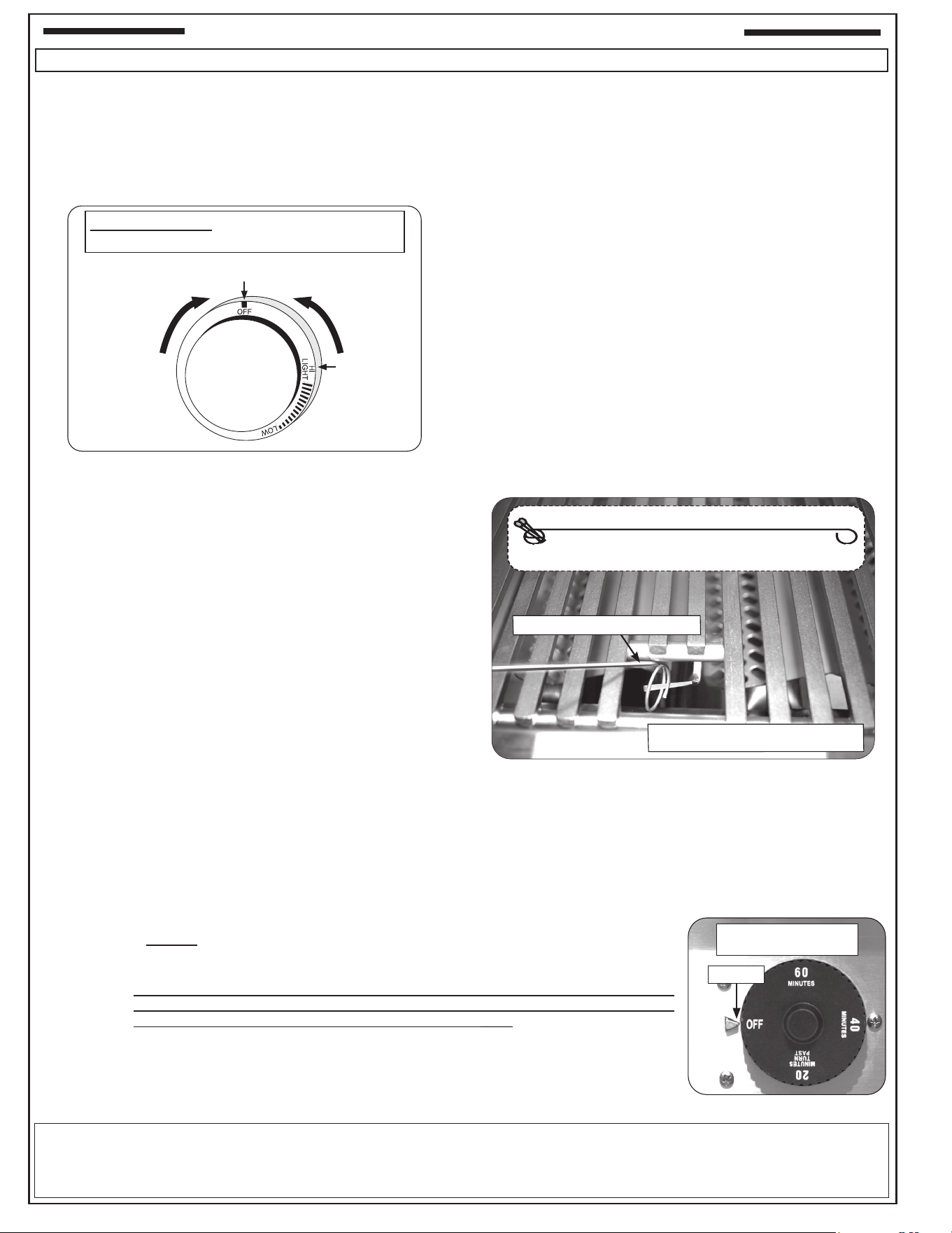
32
ALLUMAGE COMMANDE ECLAIRAGE
1. Ouvrez le couvercle du four.
2. Tournez tous les boutons de commande du gaz sur leur
position OFF.
3. Allumez le gaz à sa source. Placez le bouton de commande
du temporisateur sur le temps de cuisson souhaité. Voir la
section RÉGLAGE DE LA MINUTERIE.
ÉCLAIRAGE MANUEL
ATTENTION: Attendez toujours cinq (5) minutes le gaz pour
se dégager après que n’importe quelle tentative
non réussie d’éclairage.
1. Suivez les étapes 1 à 3 (à gauche).
2. Insérez soit un brûlant long baril briquet au butane, un match
à longue tige de brûlure, ou une allumette en feu détenues
par un titulaire d’extension de l À travers les grilles de
cuisson du brûleur (Fig. 32-2).
3. Tout en maintenant le match ou amme d’un briquet à
proximité du brûleur, appuyez sur le bouton de contrôle
approprié et en appuyant son tour dans le sens antihoraire à la
position HI LIGHT. Retirez le briquet ou des allumettes quand
le brûleur s’allume, puis relâchez le bouton de commande.
ATTENTION: Si le brûleur ne se allume pas dans les cinq (5)
secondes de tourner le bouton de commande,
appuyez immédiatement sur le bouton et
tournez la valve sur OFF. ATTENDEZ CINQ
(5) MINUTES avant de répéter les étapes 2 à 3
des instructions du MANUEL D’ÉCLAIRAGE.
4. Appuyez sur le bouton de commande souhaité et, tout en
appuyant sur cette touche, tournez-le dans le sens inverse
des aiguilles d’une montre jusqu’à la position HI LIGHT (Fig.
32-1). Une fois le brûleur allumé, relâchez le bouton.
Remarque: Tourner le bouton crée un «clic» et allume le
brûleur. S’il n’y a pas d’allumage, mettez - le
immédiatement sur OFF et répétez la séquence
rapidement jusqu’à ce que le brûleur s’allume.
ATTENTION: Si un brûleur ne s’allume pas dans cinq (5)
secondes d’allumer le bouton de commande,
enfoncez le bouton et tournez-le à la position
OFF. ATTENDEZ CINQ (5) MINUTES avant de
répéter l’étape 4. Si vous sentez le gaz, suivez
les instructions sur la couverture de ce manuel.
Si les brûleurs ne s’allument toujours pas après
que plusieurs tentatives, se rapportent aux
instructions pour l’éclairage manuel.
5. Répétez l’étape 4 pour que chaque brûleur additionnel soit Lit.
ARRÊT DU UNITÉ
Pour éteindre l’appareil, appuyez sur chaque bouton de commande
de valve et, tout en maintenant la pression, tournez-le dans le
sens horaire jusqu’à la position OFF.
Après chaque utilisation, fermez toujours la vanne de l’alimentation
en gaz de l’appareil.
Fig. 32-1 Bouton de commande
Lisez le règlage ici
(position OFF achèe)
ÉTEINDRE
SUR
Utilisation
SALUT
(haute) à la
lumière
Enfoncez le
bouton pour
tourner
NE TOURNEZ PAS plus d’une valve à la fois, que
ce soit pour l’allumage électronique ou manuel.
EMPLOYANT UN RÉSERVOIR DE PROPANE PORTATIF
Des réservoirs de propane sont équipés d’un dispositif d’arrêt de sûreté qui peut ne pas causer le bas ou aucunes pression de gaz/
amme aux brûleurs si le fonctionnement et l’allumage des instructions ne sont pas suivis exactement (voir la note importante dans la
section de DÉPANNAGE pour plus de détails).
Lisez toutes les instructions avant l’allumage, et suivez ces instructions chaque fois vous lumière le unité.
ALLUMAGE DES INSTRUCTIONS (D’ALLUMAGE)
Fig. 32-2 Allumage manuel
Porte-allumette
Insérer à travers l’ouverture, maintenir la
amme contre la surface du brûleur
Porte-allumette avec allumette
RÉGLAGE DE LA MINUTERIE (SI APPLICABLE NON INCLUS)
La minuterie doit d’abord être réglée. Tournez le cadran (sens horaire) jusqu’au temps d’arrêt désiré,
maximum 1 heure. Le cadran revient ensuite automatiquement (sens antihoraire) à OFF et coupe
l’alimentation en gaz.
Important: Pour utiliser la minuterie pour des durées inférieures à vingt minutes, tournez au-delà de
vingt (pour l’activer), puis revenez (dans le sens antihoraire) à la durée souhaitée. Cela
garantit le bon fonctionnement de la minuterie. Voir Fig. 32-3.
Remarque: Les conditions diciles, l’usure ou une mauvaise manipulation peuvent aecter la
minuterie. Il est recommandé de tester périodiquement la minuterie au moins une fois
par mois ou selon les besoins.
• Assurez-vous qu’aucun gaz ne s’écoule lorsque la minuterie atteint la position OFF.
• Si la minuterie ne s’éteint pas, faites-la remplacer par un professionnel du gaz.
Fig. 32-3 Cadran de la minuterie
Cadran de la minuterie en
position OFF
Lire ici
USE, CARE, & SERVICE
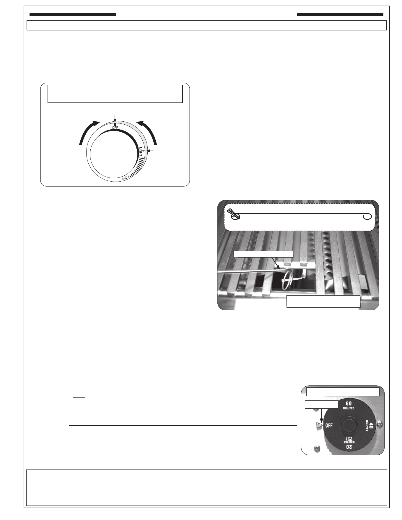
33
SPARK IGNITION LIGHTING
1. Open the oven hood.
2. Turn all gas control knob(s) to their OFF position(s).
3. Turn on the gas at its source. Set the timer control knob
to the desired cooking time. See SETTING THE TIMER
section below.
MANUAL LIGHTING
CAUTION: Always wait ve (5) minutes for gas to clear after
any unsuccessful lighting attempt.
1. Follow steps 1 through 3 (left).
2. Insert either a burning long-barrel butane lighter, a
burning long-stem match, or a burning match held by a
wire extension holder through the cooking grids to the
burner (Fig. 33-2).
3. While holding the match or lighter ame next to the burner,
depress the appropriate control knob and while pressing
turn it counterclockwise to the HI LIGHT position. Remove
the lighter or match when the burner lights, and release
the control knob.
CAUTION: If the burner does not light within five
(5) seconds of turning the control knob,
immediately depress the knob and turn
the valve to OFF. WAIT FIVE (5) MINUTES
before repeating steps 2 and 3 of the MANUAL
LIGHTING instructions.
Fig. 33-1 Control knob
Read setting here
(OFF position shown)
To Turn OFF
To Turn ON
Use
HI (high)
to light
Press
knob in
to turn
DO NOT turn on more than one valve at a time for
either spark ignition or manual lighting.
4. Depress the desired control knob, and while pressing turn
it counterclockwise to the HI LIGHT position (Fig. 33-1).
Once the burner lights, release the knob.
Note: Turning the knob will create a “click” sound and ignite
the burner. If there is no ignition, immediately turn to
OFF position and repeat sequence quickly until burner
ignites.
CAUTION: If a burner does not light within ve (5) seconds
of turning on the control knob, depress the knob
and turn it to the OFF position. WAIT FIVE (5)
MINUTES before repeating step 4. If you smell
gas, follow the instructions on the cover of this
manual. If the burners still do not light after
several attempts, refer to the instructions for
manual lighting.
5. Repeat step 4 for each additional burner to be lit.
SHUTTING OFF THE UNIT
To shut o the unit, depress each valve control knob and while
pressing turn it clockwise to the OFF position.
After each use, always close the valve from the gas supply
of the unit.
WHEN USING A PORTABLE PROPANE TANK
Propane tanks are equipped with a safety shutdown device that may cause low or no gas pressure/ame
at the burners if operating and lighting instructions are not followed exactly (See important note in the
TROUBLESHOOTING section for more details).
Read all instructions before lighting, and follow these instructions each time you light the unit.
LIGHTING (IGNITION) INSTRUCTIONS
Fig. 33-2 Manual lighting
Match holder
Match holder w/ match
Insert through opening and hold
ame against burner surface
SETTING THE TIMER
The timer must rst be set. To use, set the dial (turn clockwise) to the desired time to shut o,
up to 1 hour. The timer dial will automatically rotates (counter-clockwise) to OFF (gas supply
will shut o).
Important: When using the timer for periods of less than twenty minutes (to activate), then
return (counter-clockwise) to the desires amount of time. This will ensure proper
timer operation. See Fig. 33-3.
Note: Harsh environments, wear, abuse, or tampering may aect your timer. It is recommended
to periodically test the timer at least once a month or as needed.
• Ensure when timer reaches the OFF position, no gas continues to ow.
• If the timer does not shut o, have a gas professional replace the timer.
Fig. 33-3 Timer dial
Timer knob in OFF position
Read Here
34
Your grill requires regular cleaning and maintenance. Refer to these instructions for details. Performing these procedures
will ensure proper operation, appearance, and safety.
WARNINGS
• Prior to servicing or cleaning make sure the unit is completely cool, the control knobs are turned to the OFF position,
and the gas supply is shut o (as applicable and unless otherwise stated).
• Wear appropriate gloves and safety glasses during any servicing or cleaning.
• DO NOT spray any cleaner or liquids on the grill when hot.
• The grill MUST be cleaned regularly to prevent grease build-up and other food deposits. A clean and well maintained
grill prevents the risk of grease build-up and grease res.
• Verify proper operation after servicing or deep cleaning.
• See INSTALLATION, OPERATION, AND SAFETY INFORMATION section for additional related information.
CLEANING YOUR GRILL
Before Each Use
1. Inspect and clean the exterior surfaces of the unit: With a cool grill, clean any dust, grease, splatter, or spills as
needed with a damp clean cloth.
After Each Use
1. Perform a burn-o and clean the cooking grids: Operate the grill on high with the hood closed for 15 minutes to
burn-o food and grease and allow for an easier cooking grid clean. Then turn OFF the grill and use a grill brush or
scraper to clean the cooking grids of all residue. Use long-handled insulated BBQ tools and wear an insulated glove
/ oven mitt.
2. Check and clean your drip tray: When the grill is cool, carefully remove the drip tray and dispose of contents appropriately.
If tray is equipped with a liner, dispose of the liner. Clean tray in a soapy water solution if needed. For tough deposits,
a copper pad can be used. Rinse and dry completely. Replace a new liner and insert the tray back into the grill. Order
more drip tray liners through your local dealer.
3. Cover your grill: Once the grill is dry and cool, cover your grill with a Fire Magic protective cover (not included).
Twice A Year (or as needed) - Deep Clean
1. Interior of grill: In addition to cleaning the cooking grids and drip tray, a deep clean of the interior of
the grill, burners, and all components MUST be performed twice year (or as needed depending on
use). Refer to the CARE, CLEANING, & MAINTENANCE GUIDE provided with your grill, or simply
scan the QR code on the right.
Important: The burner ports and carry-over ports/slots MUST be kept clean to ensure proper ignition
and operation. The guide provides all details on cleaning.
2. Exterior of grill: With a cool grill, use a grill cleaner (or a soapy water solution)
and a clean cloth to remove grease and dirt from the outside of the grill. For tough
deposits, a copper pad can be used. Always wipe with the grain. Rinse and dry
completely. Then follow up with a stainless steel cleaner and a clean cloth. DO
NOT use other cleaners or chemicals.
If this routine cleaning is not performed, the stainless steel may become dull and
develop surface rust (due to use and atmospheric conditions). If left uncleaned,
signicant damage and pitting may occur.
Important: DO NOT use steel wool, any other metal tools, or any other cleaners/chemicals to clean the exterior
other than recommended above. Such items promote rust.
Note: Due to the nature of stainless steel, temperatures produced by the grilling process will cause discoloration. This
can be reduced by routine cleaning.
SERVICING AND CLEANING
Wipe with grain
Fig. 34-1 Wipe with grain
35
For Environments High In Salt, Chloride, Or Other Corrosive Chemicals
When this grill is installed in a corrosive environment such as near the ocean (salt air), poolside (chlorine and/or
pool chemicals) or any other location with exposure to high salt/chloride content or corrosive chemicals/solutions,
it will be more susceptible to corrosion and MUST be maintained/cleaned more frequently.
• DO NOT store any corrosive chemicals (chlorine, hydrochloric acid, fertilizer, etc.) near your stainless steel grill.
• DO NOT allow any corrosive materials (masonry dust, debris, etc.) to settle on your stainless steel grill.
• These environments, chemicals, and materials may cause the 304 stainless steel to develop surface rust and
consequently pitting. Under these conditions the grill exterior MUST be cleaned at least monthly. Inspect your grill
often and clean accordingly.
Protecting Your Grill
An optional Fire Magic protective cover will protect your grill when not in use. Install the cover on a cool and dry grill. DO
NOT cover a damp grill. During high humidity or after rainy conditions, remove the cover to dry trapped moisture if present.
(If the cover is installed over a damp grill it can cause surface rust.)
Ensure that the INSIDE of the cover is DRY before putting it back on the grill.
SERVICING AND CLEANING (Cont.)
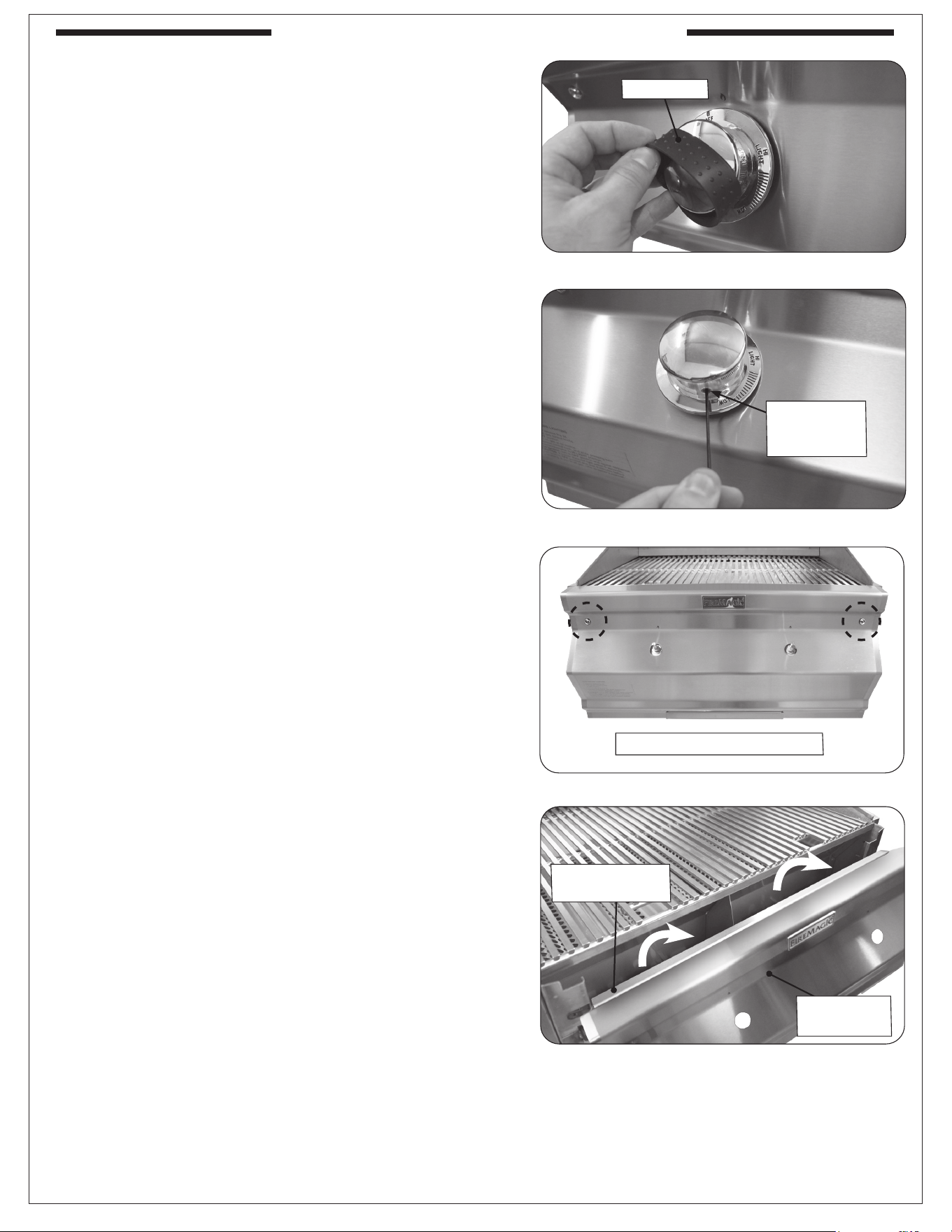
36
CONTROL PANEL REMOVAL
Note: Wear heat-resistant gloves if necessary.
1. Turn the control knobs to the OFF position and turn
o the gas supply to the unit.
2. Remove the rubber grip from a control knob (see Fig.
36-1).
3. Insert the included .078" (2mm) hex key through the
small hole located on the side of the knob and loosen
the screw (see Fig. 36-2).
4. Pull the control knob from the stem to fully remove.
5. Repeat for the other knobs.
6. Remove the drip tray.
7. Using a Phillips screwdriver, unscrew and remove the
control panel fastener screws and washers (located on
the left and right front face of the control panel). See
Fig. 36-3. Retain the screws for later re-installation.
8. Carefully remove the control panel by lifting and pulling
the control panel from the frame (see Fig. 36-4).
Note: Ensure the cooking grid locking channel remains
attached to the control panel when reinstalling. See
INSTALLATION - SECURE THE COOKING GRIDS
section for details.
WARNING: During reinstallation: prior to opening the gas
shut-o valve, be sure the control knobs are
in the OFF position.
Rubber grip
Fig. 36-2 Loosen screw to free knob
Loosen screw
(inside hole)
with hex key
Fig. 36-3 Screws removal
Fig. 36-4 Control panel removal
Remove
control panel
Remove screws and washers
Cooking grid
locking channel
Fig. 36-1 Rubber grips removal
SERVICING AND CLEANING (Cont.)
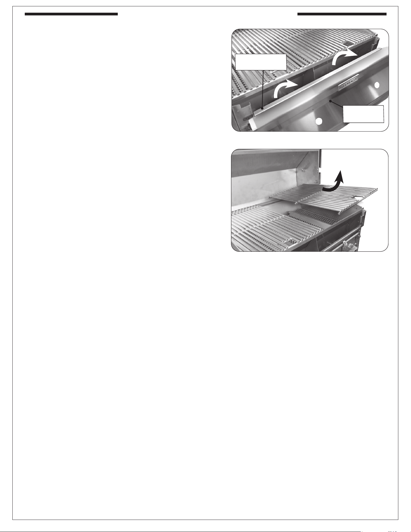
37
COOKING GRID REMOVAL
Note: Wear heat-resistant gloves if necessary.
1. Turn the control knobs to the OFF position and turn
o the gas supply to the unit.
2. Remove the control panel. Ensure the cooking grid
locking channel is removed along with the control
panel (see Fig. 37-1). See the CONTROL PANEL
REMOVAL section for details.
3. Carefully remove the cooking grids (see Fig. 37-2).
Fig. 37-2 Cooking grids removal
Fig. 37-1 Control panel / grid locking channel removal
Remove
control panel
Cooking grid
locking channel
SERVICING AND CLEANING (Cont.)
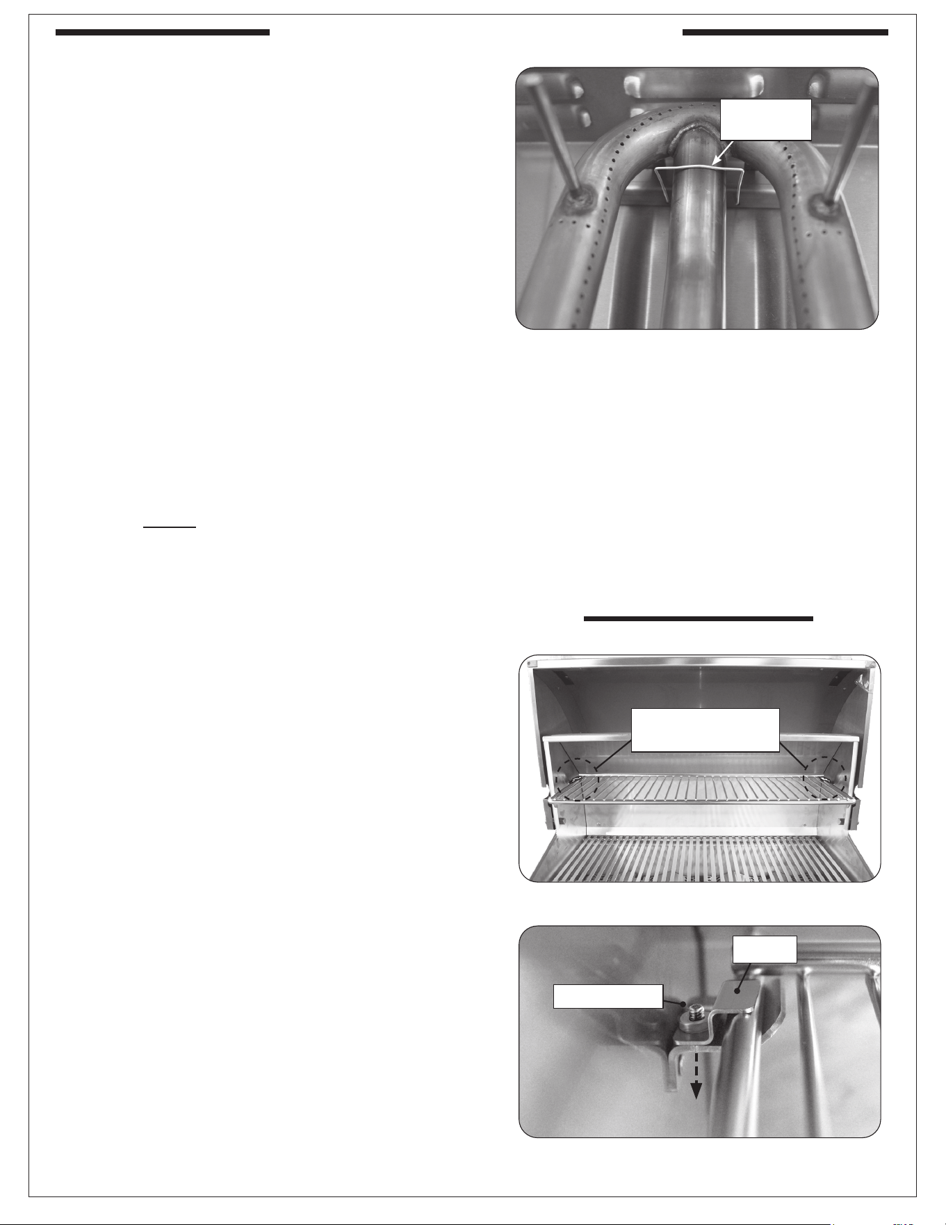
38
BURNER REMOVAL
1. Ensure the knobs are in the OFF position, and
the gas supply is turned o.
2. Remove the control panel, cooking grids, and
avor grids and set them aside. See the CONTROL
PANEL REMOVAL and COOKING GRID REMOVAL
sections for details.
3. Locate the burner clip (located over the rear center
tube of the burner) and slightly pinch and remove
the clip from the burner support. See Fig. 38-1.
4. Carefully lift the burner from the burner support
anchor peg holes and out from the hole in the
forward re wall.
5. To replace the burner, slide the open cylindrical
end of the burner around the orice, enveloping
it and centering on it. Then lower the back end
anchor pegs into the burner support anchor peg
holes.
Note: It is critical to the continued safe functioning of
the burners that the orices are centered and
completely inside the burner gas inlets.
6. Re-install the burner clip around the burner and
into the holes in the burner support.
7. Replace the avor grids, cooking grids, and control
panel.
Fig. 38-1 Main burner removal
Remove
burner clip
WARMING RACK REMOVAL
Note: Wear heat-resistant gloves if necessary.
1. Locate the warming rack locking brackets found
on the rear left and right side of the warming rack
(see Fig. 38-2).
2. Use a short-handled Phillips screwdriver to
remove the screw from a locking bracket. Then
remove the bracket. See Fig. 38-3.
3. Repeat for the other bracket.
4. Carefully remove the warming rack by lifting the
front end up from the hooks, then outward.
Important: When reinstalling, place cardboard (or
similar) on the cooking grid surface to
prevent the screws from falling down into
the unit.
Fig. 38-2 Warming rack locking brackets
Locate warming rack
locking brackets
Fig. 38-3 Warming rack locking bracket removal
Bracket
Remove screw
SERVICING AND CLEANING (Cont.)
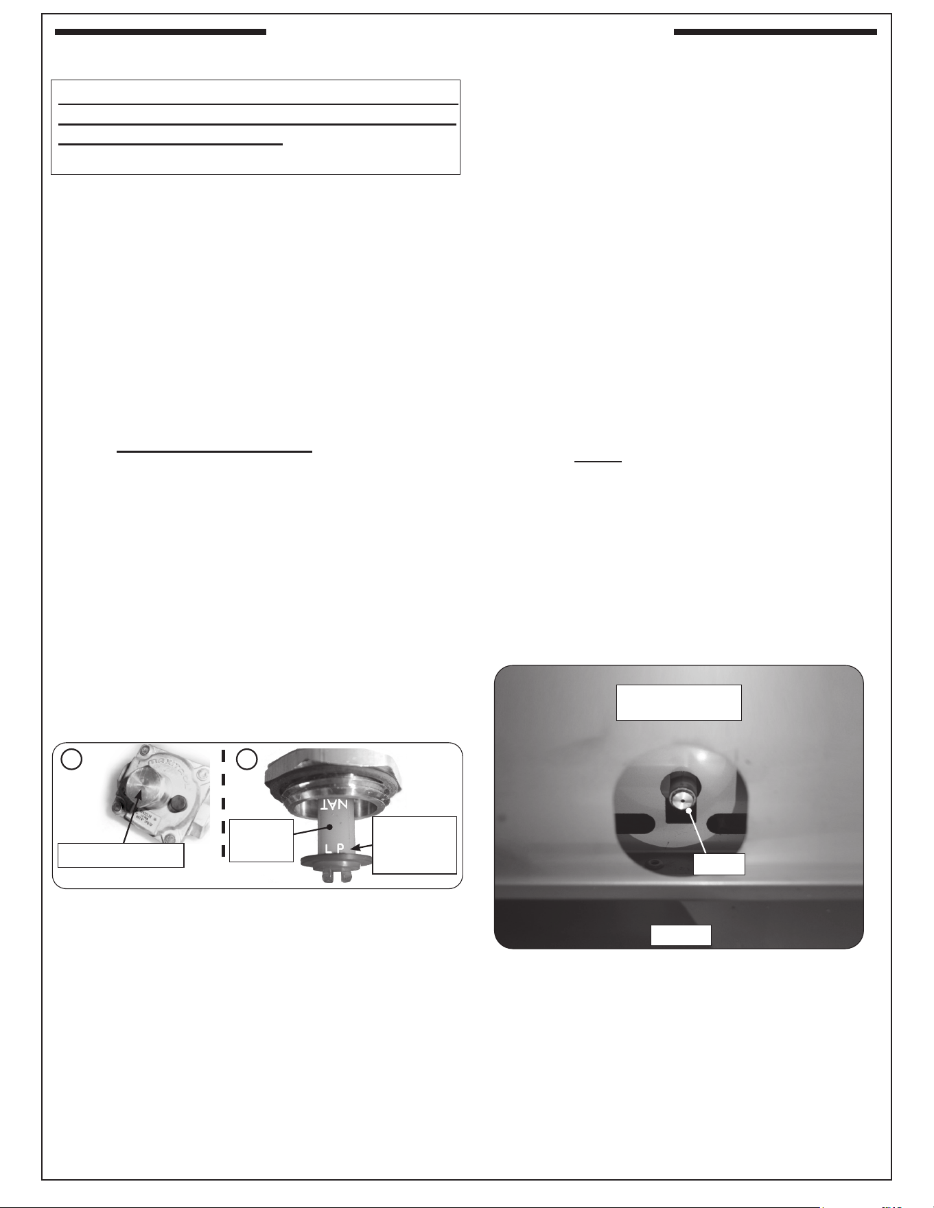
39
SERVICING AND CLEANING (Cont.)
CONVERTING THE GAS TYPE
CAUTION: Make sure the grill is at a safe temperature
and isolated from gas and electrical supplies
before beginning.
For your safety, exercise caution, and make sure you
have adequate hand protection, such as gloves, when
handling metal parts.
Apply Conversion Label
This grill comes from the factory congured for one type
of gas as marked on the label behind the control panel.
When the grill is converted, the label for the new gas
(included at original shipping) MUST be lled out and
applied next to the existing label mentioned above.
Convert Regulator
The gas regulator, located behind the control panel (see
CONTROL PANEL REMOVAL section), must be set for
the type of gas used to fuel the grill. To check the regulator
setting, remove the cap in the center of the regulator (Fig.
39-1, A). Holding the cap vertical (see Fig. 39-1, B), the
letters at the bottom of the plastic stalk indicate the gas
type for which the regulator is currently congured.
If the text on the bottom of the regulator stalk does not
match the gas type connected to the grill, remove the
stalk from the cap, invert, and replace into center of cap.
Replace cap on the regulator, screwing down until snug.
Convert Gas Orices
When converting the grill to a dierent gas type,
each burner’s orice must be replaced with the
corresponding orice for the new gas.
See
MODEL SPECIFICATIONS TABLE, Table 2 to
determine the proper orice sizes for each burner.
Important: It is critical to the operation of each
burner that its orice be fully inserted
into the center of its orice opening.
WARNING: HAZARDOUS OVERHEATING
WILL OCCUR IF A NATURAL-GAS
ORIFICE IS USED WITH PROPANE
GAS.
1. Remove the control panel, cooking grids,
and avor grids and set them aside. See the
CONTROL PANEL REMOVAL and COOKING
GRID REMOVAL sections for details.
2. Remove the burners. See BURNER REMOVAL
section for details.
3. Use a
3
/
8
" hex nut driver to remove the exposed
orice (Fig. 39-3). Check orice. If needed, replace
it with the correct orice for the new gas.
4. Replace the burners.
Note: It is critical to the continued safe functioning
of the burners that the orices are centered
and completely inside the burner gas inlets.
5. Replace the avor grids, cooking grids, and control
panel.
Connect To New Gas Supply
Plumb the unit as appropriate for the new gas supply.
(Additional components may be needed for your specic
setup.) Be sure to leak test at all connections.
Fig. 39-1
A B
Invert if
needed
Gas regulator cap
Read gas
type here
(LP shown)
Orice
Forward rewall
(view from within grill)
Fig. 39-2
WHEN CONVERTING TO A NEW GAS TYPE, THE
ENCLOSURE MUST HAVE PROPER VENTILATION
FOR THE NEW GAS TYPE. See the ENCLOSURE
REQUIREMENTS section for complete details.
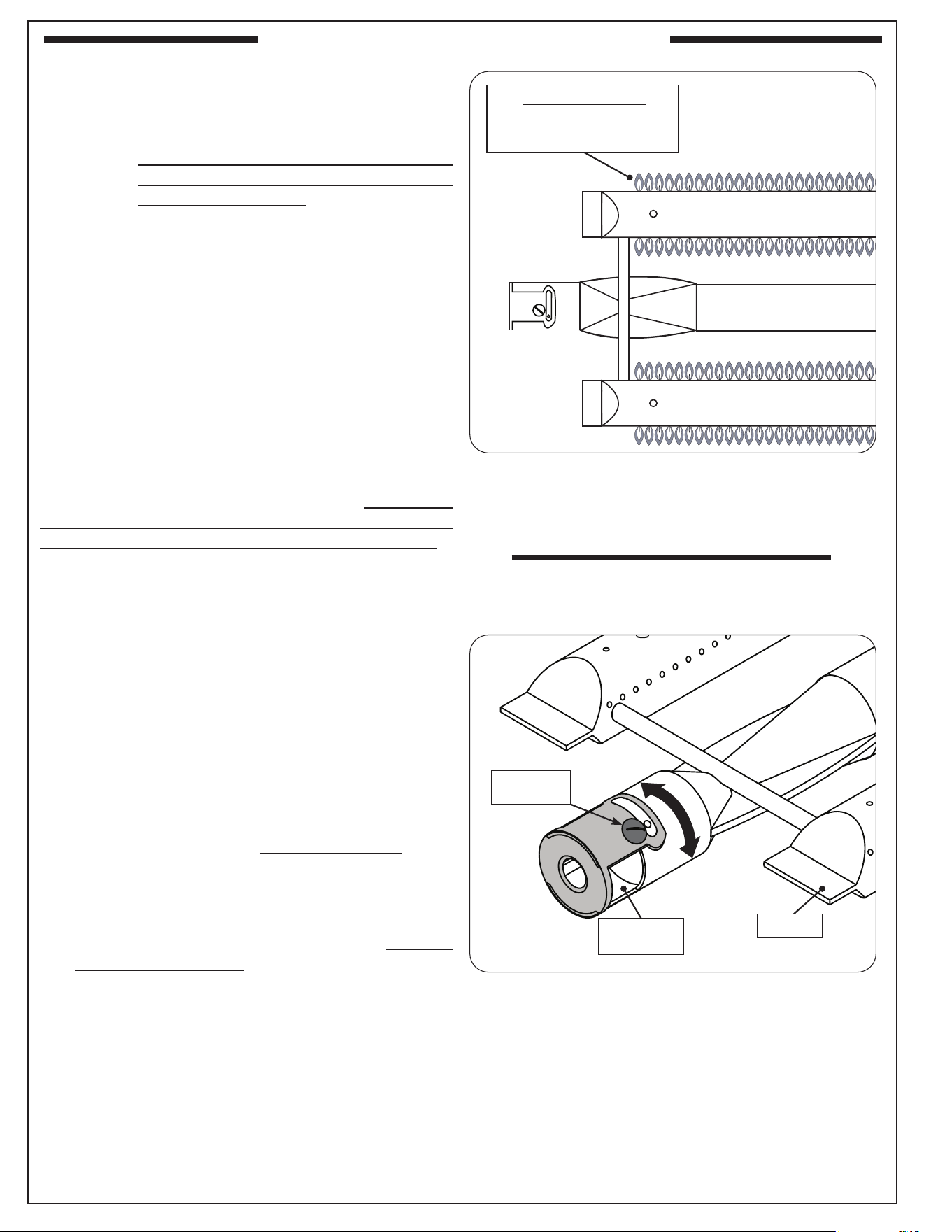
40
AIR SHUTTER ADJUSTMENT / BURNER
FLAME INSPECTION
Important: Air shutters are preset at the factory (see
Table 2 in MODEL SPECIFICATIONS).
However, gas conversion, altitude, or other
local conditions may make it necessary to
adjust the air shutters.
Note: To verify proper settings, the flames of the
burners should be visually checked for proper
ame appearance and behavior. Light the grill
with the burner(s) on HI setting. Allow at least 2
minutes to burn. See below and Fig. 40-1. The
ames should:
• be blue and stable with little to no yellow tips
• burn quietly, and appear to touch the burner
If the ames appear unstable, yellow, noisy, or lift away
from the burner, follow the steps below.
Main Burner
Begin with a completely cool unit. Remove the
burners (see BURNER REMOVAL section). First ensure
the burner orice, ports, venturi tubes, and air shutter
openings are all clear of any insect or insect nests. If
they are blocked, clean them, reinstall the burners, and
reinspect the ames. If adjustment is still needed, allow
the unit to cool, remove the burner, and proceed to the
steps below.
1. To adjust the air shutter, loosen the adjustment
screw with a athead screwdriver. Then rotate the
shutter to open or close it. See Fig. 40-2 for details.
• Begin with the appropriate factory setting for your
model (see Table 2 if needed).
• If the ames were excessively yellow (insucient
air), open the shutter to allow more air to the
burner. If the ames were noisy and lifting o the
burner in some areas, close the shutter to allow
less air to the burner. Adjust accordingly.
Note: Make minimal adjustments. Very small changes
result in major changes in ame appearance.
2. Reinstall the burner, light the grill with the burner
on HI, and observe the ames. If needed, allow the
grill to completely cool, and repeat the adjustment
process until the proper ame is achieved.
3. Once nished, allow the unit to completely cool,
remove the burner, and tighten the adjustment
screw. Reinstall the burner.
4. Repeat for all other main burners as needed.
5. Reinstall all other components that were removed.
Fig. 40-1 Proper ame appearance
Fig. 40-2 Main burner air shutter adjustment detail
Air shutter
opening
Adjustment
screw
CLOSE
OPEN
(burner)
T
O
R
A
T
E
Main Burner Flames:
• blue
• stable
• quiet
• touching burner
SERVICING AND CLEANING (Cont.)
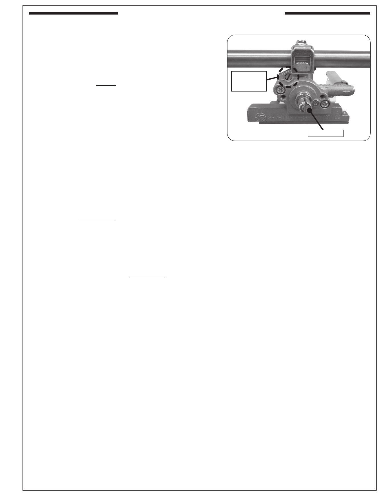
41
VALVE "LOW" SETTING ADJUSTMENT
Stability of the "low" setting on all burners may vary due to
wind direction, appliance conguration, and position. If your
burner goes out when set on low, the valve "low" setting needs
adjustment.
Note: Adjustments MUST only be performed by a qualied
professional service technician.
To adjust the valve "low" setting:
1. Ensure the unit is completely cool and the knobs are
in the OFF position.
2. Remove the control panel, cooking grids, and avor grids
and set them aside. See the CONTROL PANEL REMOVAL
and COOKING GRID REMOVAL sections for details.
3. Re-install the control knobs on the valve stems with the
control panel removed.
4. Light the burner on HIGH, then turn the burner to LOW
setting. While the burner is lit, remove the control knob
from the valve.
5. Locate the FLATHEAD adjustment screw found above the
valve stem and below the manifold (see Fig. 41-1).
6. Using a athead screwdriver, slowly turn the adjustment
screw a little at a time (30° to 45°) in either direction. Adjust
the screw as needed until the ame is approximately
1
/4" in
height from all the burner ports, and the ames are stable.
CAUTION: Only adjust the FLATHEAD screw. Adjusting
other screws may result in a dangerous gas leak.
7. Once the appropriate setting is reached, re-install the
control knob and shut o the burner valve.
8. Repeat this procedure for other burner valves, if needed.
9. Re-install the avor grids, cooking grids, control panel, and
any other components that were removed.
Fig. 41-1 Valve adjustment screw location
Valve
adjustment
screw
Valve stem
(Manifold)
(Manifold)
SERVICING AND CLEANING (Cont.)

42
NOTES PAGE
Please use this page to record any information about your unit that you may want to have at hand.
43
If you have trouble with the unit, please use this list to identify the problem. By trying one or more of the solutions
to the possible cause, you should be able to solve the problem. If this list does not cover your present problem,
or if you have other technical diculties with the unit, please contact your local dealer.
Table 2
PROBLEM POSSIBLE CAUSE CORRECTION
Ignition system
failure
1. Improper air shutter adjustment
2. No spark generated at the valve
3. Low gas pressure
4. Front carry-over ports clogged
5. Igniter malfunction
6. Igniter electrode sparking to rebox and
not to ame tube
1. Adjust air shutters.
2. Retry to light. If ignition failure continues,
contact dealer for valve replacement.
3. Have the gas co. check supply pressure.
4. Clean burner ports.
5. Contact dealer for replacement.
6. Adjust ame tube to ensure it receives the
spark.
Insucient heat /
low ame
1. Burner ports partially blocked by debris
2. Improper air-shutter adjustment
3. Using propane orice for natural gas
4. Low gas pressure/ame (propane)
5. Low gas pressure/ame (natural)
6. L.P. regulator hose stuck/damaged
1. Remove burners and clean out ports.
2. Adjust air shutters.
3. Check/change orices.
4. Shut o all valves, including propane tank,
and follow lighting instructions exactly. (See
important note* below.)
5. Have a qualied professional service technician
check for proper gas supply, setup, and
pressure.
6. Replace L.P. regulator hose.
Uneven heating
1. Burner ports partially blocked by debris
2. Small spiders or insects in burner
3. Improper air shutter adjustment
1. Remove burners and clean out ports.
2. Inspect burners and orices for spider webs or
other debris that may block ow.
3. Adjust air shutters.
Burner goes out on
LOW
1. Valve “Low” setting needs adjustment
1. Light burner on HIGH, immediately turn to
LOW setting. Remove knob from valve and
using a small at screwdriver, slowly turn the
adjustment screw in the stem, a little at a time
(30° to 45°), in either direction, until the ame is
approximately
1
/4” in height from burner ports.
* Important: Propane tanks are equipped with a safety shutdown device that may cause low or no gas/ame at the
burners if operating and lighting instructions are not followed exactly. If you suspect the propane tank
safety shuto is in eect: 1) Shut o all grill valves. 2) Shut o tank valve. 3) Open and close a main
burner valve. 4) Open tank valve. 5) Follow the LIGHTING INSTRUCTIONS. Lighting instructions are
located in your owner’s manual and printed on the grill’s metal drip tray. If the problem persists, continue
troubleshooting, or contact your local dealer or R. H. Peterson for assistance.
TROUBLESHOOTING
44
R.H. Peterson Co. • 14724 East Proctor Avenue • City of Industry, CA 91746
Quality Check
Date:____________
Burner
Orices
Nat. L.P. Leak Test: _________
Main: ____ ____
Burn Test: _________
Gas Type: Nat. / L.P.
Other: ____ ____ Air Shutter: _________
Inspector: _____________________
Model #:
Serial #:
COMMONWEALTH OF MASSACHUSETTS REQUIREMENTS
This appliance is approved for installation in the state of Massachusetts subject to the following requirements:
Install this appliance in accordance with 248 C.M.R., the Rules and Regulations Governing Plumbers and Gas Fitters. The
installer or service agent must be a plumber or gas tter licensed in the Commonwealth of Massachusetts. The exible gas
line connector used must not exceed 36 inches (92 centimeters) in length. The individual manual shut-o must be a T-handle
type valve, listed and approved by the state of Massachusetts.
A COPY OF YOUR SALES SLIP FOR PROOF OF PURCHASE IS REQUIRED
This warranty applies to the original purchaser for products which are installed in the United States or Canada. This warranty is valid only with proof of purchase,
commences on the date of purchase, and terminates (both as to original and any replacement products) on the anniversary date of the original purchase of
the product per the above schedules.
This warranty does not cover parts which become defective as a result of negligence, misuse, or use not in compliance with the Installation and Owner’s
Manual, accidental damage, improper handling, improper storage, improper installation, lack of required routine maintenance (as specied in the Installation
and Owner’s Manual), electrical damage, local gas impurities or failure to protect against combustible materials. Product must be installed (and gas must be
connected) as specied in the Installation and Owner’s Manual by a qualied professional installer. This warranty does not apply to normal occurrences
that may be expected with any outdoor product such as rust, corrosion, oxidation, or discoloration unless the aected part becomes inoperable. RHP products
including valves, pilots and controls are designed and certied to be used as a system. Modications to products which are not specically authorized will void
this warranty and could render the product to be unsafe. Burners, valves, parts, remotes, accessories, etc. used with this product must be RHP products or
this warranty is void.
Warrantied items will be repaired or replaced at RHP's sole discretion. This warranty does not cover labor or labor related charges, except as provided by
separate specic written programs from RHP. All repair work must be performed by a qualied professional service person and requires prior approval of RHP.
RHP may require the defective product or part to be returned to the factory to determine the cause of failure. RHP will pay freight charges if the product or part
is determined to be defective. This warranty does not cover breakage in shipment from our independent distributor to its customer if the damage is determined
to have occurred during that shipment.
This warranty specically excludes liability for indirect, incidental, or consequential damages. Some states and provinces do not allow the exclusion or
limitation of incidental or consequential damages, so the above exclusion may not apply to you. This warranty gives you specied legal rights, and you may
have other rights that vary from state to state or province.
For additional information regarding this warranty, or to place a warranty claim, contact the RHP dealer where the product was purchased.
When contacting your RHP dealer or the R.H. Peterson Co., please provide the following information:
- Your name, address, telephone number, e-mail
- Sales receipt showing where purchased and date purchased
- Model number, serial number of product, date code
- Relevant information: installer, additions, repairs, when defect was rst noted
TO REGISTER YOUR PRODUCT ONLINE GO TO: WWW.RHPETERSON.COM,
AND CLICK ON PRODUCT REGISTRATION. THANK YOU FOR YOUR PURCHASE.
PETERSON FIRE MAGIC COMMERCIAL / MULTI-USER GRILLS AND ACCESSORIES
LIMITED WARRANTY
When used in a commercial / multi-user setting* including but not limited to apartment complexes, multi-family dwelling complexes,
schools, hotels, re stations, police stations, etc.
*Excluding restaurants and other professional cooking settings.
R.H. Peterson Co. ("RHP") warrants your Fire Magic
®
grill to be free from defects in material and workmanship.
Fire Magic
Stainless steel grill housing, burners, stainless steel rod cooking grids, brass valves, inner liners and manifold assemblies are warranted
for FIVE (5) YEARS.
Fire Magic
exterior Glass Fiber Reinforced Concrete (GFRC) grill island systems are warranted for ONE (1) YEAR.
All other components, except batteries, are warranted for ONE (1) YEAR.
WARRANTY