MILWAUKEE TOOL
l
www.milwaukeetool.com
13135 W. LISBON RD., BROOKFIELD, WI 53005
Drwg. 1
SERVICE PARTS LIST
BULLETIN NO.
PN0013881
SPECIFY CATALOG NO. AND SERIAL NO. WHEN ORDERING PARTS
REVISED BULLETIN
DATE
Apr. 2026
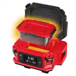
M18™ Jobsite Lunch Warmer
WIRING INSTRUCTION
See Page 2
CATALOG NO. 0811-20 SERIAL NO. S35A
NAMEPLATE SPECIFICATIONS: 18 V
FIG. NOTES
17 If replacing the housing, FIG. 68 Service Nameplate is required.
68
17
43
50
40
(2x)
38
8 14
15
65
41
(2x)
42
(2x)
38 40
41 42
62
16
(2x)
15
14
8
(8x)
29
(4x)
32
31
29 31
32
66
19
26
1
(4x)
1 19
26
64
7
6
5
4
3
1
(2x)
2
(16x)
6
7
67
1 2 3
4 5
63
38 40 41
42 43 50
61
37
36
35
35 36
37
60
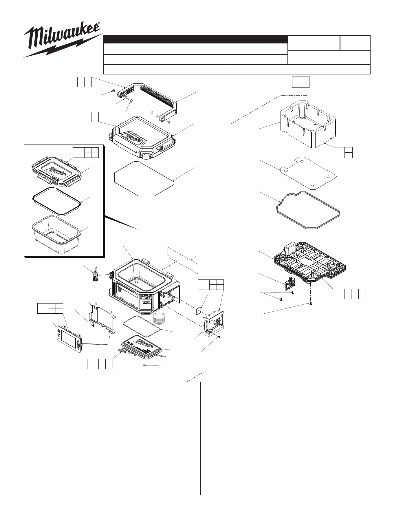
FIG. PART NO. DESCRIPTION OF PART NO. REQ.
1 06-82-0811 M3 x 10mm PH T-10 ST Screw (6)
2 06-04-0811 M4 x 12mm PH T-20 ST Screw (16)
3 --------------- Packout Locker (1)
4 --------------- Bottom Plate (1)
5 45-06-0319 Gasket (1)
6 --------------- Mylar (1)
7 --------------- Foam (1)
8 23-44-0811 M2 x 6mm Philips Head ST Screw (8)
14 --------------- Heating Element (1)
15 26-72-0811 Healing Element Gasket (1)
16 44-20-0811 Housing Lid Latch (2)
17 14-38-0811 Housing (1)
19 45-06-0811 Battery Interface Gasket (1)
26 --------------- Battery Interface (1)
29 06-75-0811 M2.6 x 8mm Philips Head ST Screw (4)
31 --------------- Screen/PCBA (1)
32 28-50-0811 Screen/PCBA Housing (1)
FIG. PART NO. DESCRIPTION OF PART NO. REQ.
35 --------------- Container Lid (1)
36 45-07-0319 Container Gasket (1)
37 --------------- Container (1)
38 --------------- Handle (1)
40 06-82-0319 M4 x 8mm PH T-20 Machine Screw (2)
41 45-88-0811 Handle Washer (2)
42 34-40-0811 Handle O-ring (2)
43 --------------- Outer Housing Lid (1)
50 45-07-0811 Housing Lid Gasket (1)
60 49-16-0202 Container w/Lid, 4 Cup (Accessory) (1)
49-16-0203
Container w/Lid, 4 Cup (Accessory) Set Of 3
(1)
61 42-92-0811 Lid Assembly (1)
62 14-46-1007 Handle Kit (1)
63 44-66-0811 Bottom Plate Kit (1)
64 44-81-0811 Battery Rail Kit (1)
65 14-20-0811 Heating Element Assembly (1)
66 14-46-0812 Screen/PCBA Assembly (1)
67 23-14-0811 Insulation Kit (1)
68 12-20-0811 Service Nameplate (1)
0
00
EXAMPLE:
Component Parts (Small #)
Are Included When Ordering
The Assembly (Large #).
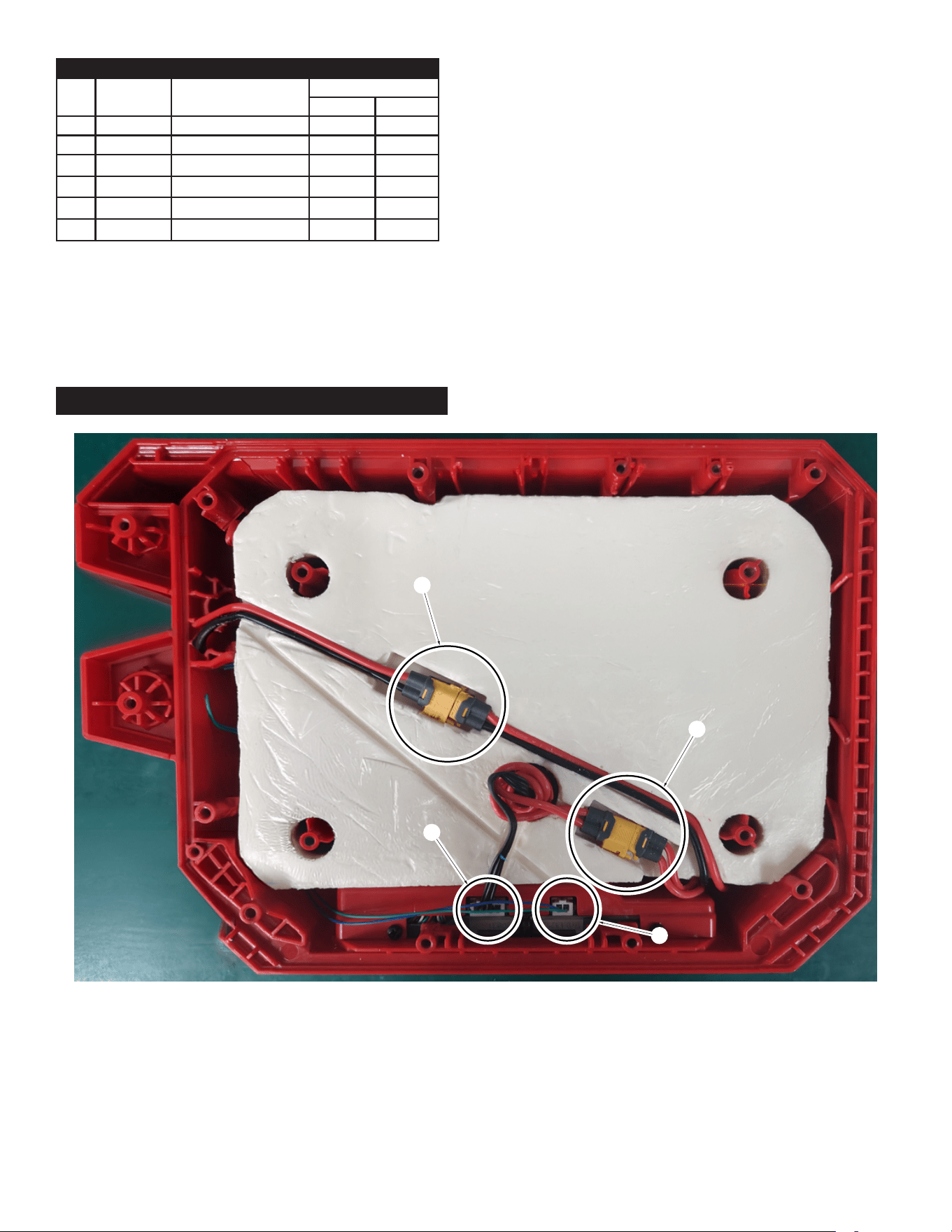
1) Connect Battery Terminal Wire with the PCB Power Terminal Wire.
2) Connect the PI Heating Film Wire with the PCB Film Wire.
3) Assemble the Thermosensitive Electronic Wire and the PCB Thermosensitive Terminal Wire.
4) Assemble the Battery Signal Wire with the PCB Signal Wire.
5) Take notice of wire routing and position in wire guides and traps while dismantling tool. Be sure that all components of the electronics
kit are seated rmly and squarely in recesses. Avoid pinched wires, be sure all wires and sleeves are pressed completely down in wire
guides and traps. Prior to installing bottom cover, be sure there are no interferences.
WIRING INSTRUCTIONS
SCREW TORQUE SPECIFICATIONS
FIG. PART NO. WHERE USED
SEAT TORQUE
kgf-cm lb-in
1 06-82-0811 Bottom Plate 5±0.5 4±0.4
1 06-82-0811 Battery Interface 3.5±0.5 3±0.4
2 06-04-0811 Bottom Plate 10.5±0.5 9±0.4
8 23-44-0811 Heating Element 2.5±0.5 2±0.4
29 06-75-0811 PCBA Housing 3.5±0.5 3±0.4
40 06-82-0319 Handle 4.5±0.5 4±0.4
1
2
3
4