
Page 1 of 155
VoIP System Guide
Technical User Guide Document
v780
© September-2025 RTX A/S, Denmark

Trademarks
RTX and all logos thereof are trademarks of RTX A/S, Denmark.
Other product names used in this publication are for identification purposes and may be trademarks of the respective
companies.
Disclaimer
This document and the information contained is property of RTX A/S, Denmark. Unauthorized copying is not allowed.
The information in this document is believed to be correct at the time of writing. RTX A/S reserves the right at any time
to change the said content, circuitry, and specifications.
Confidentiality
This document should be regarded as confidential.
© 2026 RTX A/S, Denmark, all rights reserved
Stroemmen 6, DK-9400 Noerresundby
Denmark
P. +45 96 32 23 00
F. +45 96 32 23 10
www.rtx.dk
1 About This Document
This document aims to present the Digital Enhanced Cordless Telecommunications (DECT) solutions from RTX
and describe in detail their configuration, customization, management, and operation.
This manual will enable you to set up components in your network and deploy a fully functional system.
However, it is not intended as a comprehensive reference to all details and specific steps on how to configure
other vendor specific components/devices in a SME VoIP System. For a specific customer mode, please
contact the respective vendor for documentation.
1.1 Terms and abbreviations
ABBREVIATION DESCRIPTION
DECT Digital Enhanced Cordless Telecommunications
SME Small and Medium Scale Enterprise
VoIP Voice over Internet Protocol
LAN Local Area Network
PoE Power over Ethernet
NB Narrowband
WB Wideband
MMI Man Machine Interface
NAT Network Address Translation
P2P Peer-to-Peer
PTT Push-to-Talk
1.2 Document History
The table below maps the history of this document, what firmware version it matches and the updates that
have been made to it.
REVISION
VERSION
AUTHOR ISSUE DATE UPDATES
1.0 V750
LIP 13-9-2024
Updated to match V750 Firmware.
2.0 v760 LIP 38-01-2025 Updated to match V760 Firmware
3.0 V770 LIP 23-05-2025 Updated to match V770 Firmware
4.0 V780 LIP 23-09-2025 Updated to match V780 Firmware
1.3 What is new?
What new features have been added to the current revision.
REVISION FEATURE
1.0 7.1.5 Servers – Table updated to match v750
7.1.7.10 Ring Tone Selection
7.1.17 Warning shows when unsupported repeater
2.0 7.1.4.6 Menu configuration

1.4 Related Documentation
List of documentation referred to in this guide.
REFERED DOCUMENT REVISION VERSION COMMENTS
Firmware update guide. (9430-8660-HS).pdf
1.0 v700
RTX 725x Headsets system guide.pdf
4.3 v770
RTX provisioning guide.pdf
1.5 v700
RTX VoIP DECT System Traffic Planning and
Deployment .pdf
1.0 v700
1.5 Documentation Feedback
We always strive to provide excellent customer service and therefore, we value your comments and
suggestions concerning our documentation. If you have any comments about this guide, please enter them
through the Feedback link on the RTX website. We will use your feedback to improve the documentation.
7.1.6.2 VLAN Settings - Table updated – Tag L2 packets
7.1.7.5 Text messaging – Table updated – Alarm soring
7.1.14.1 Multicell settings – Table updated - Hierarchical relay
3.0
7.1.7.1, 7.1.12, 7.1.21.3, 7.1.26 Important notes and updates added to fit the
European RED compliance requirements
7.3.4.5 Reset handset after wrong PIN added to
7.1.2 System information details about the states of base station added
2 DECT system overview
In a typical telephony system, the network setup is the interconnection between base stations, “fat” routers,
repeaters, handsets, etc. The handsets use the DECT technology to communicate with the base stations. The
base stations use a third-party call system to communicate and control the call functions. The repeaters
extend the rage of the signal of the base stations, thus providing a wider range for handling the user’s calls.
These devices ensure user efficiency across different industries, as an RTX solution can be used in various
businesses - from general offices and call centers to storage facilities, hospitals, manufacturing, and retail.
The backbone of the network depends on the deployment scenario, but a ring or hub topology is usually
used. The network has centralized monitoring and maintenance system.
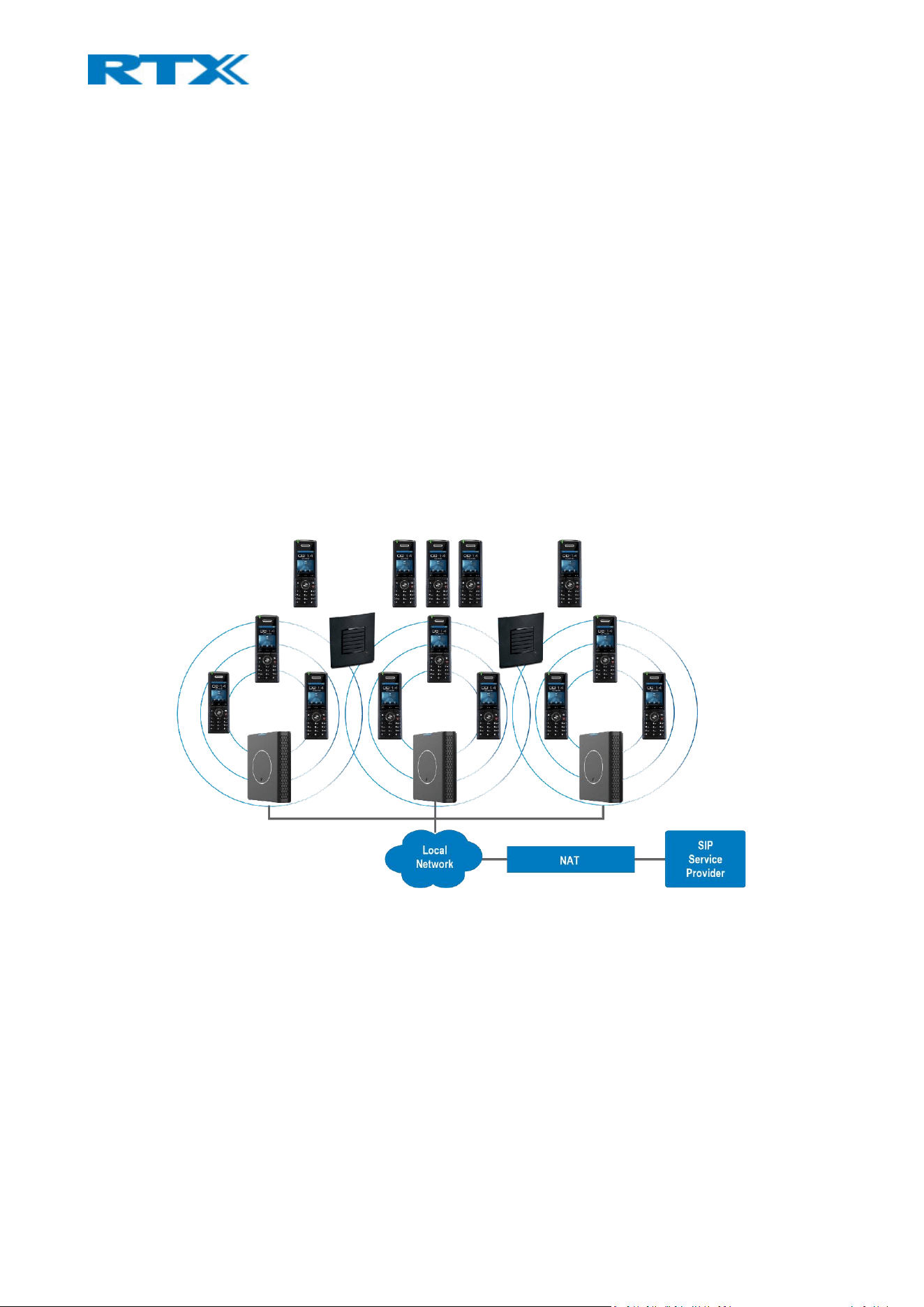
A graphical overview of the architecture of the SME VoIP system setup is illustrated below (Fig.1). Depending
on the choice of bases (B700/730 or B760), the system can support from 1 to 249 bases in the same network,
and up to 1000 registered handsets. Based on PoE interface, each base station is easy to install without
additional wires, other than the LAN cable. The system supports the IP DECT repeater, RTX4027, with support
up to 5 channels for simultaneous call sessions.
Figure 1 SME VoIP system
2.1 Deployment
An SME system setup can be deployed as follows:
Single cell setup: Telephony network composed of one base station.
Multi cell setup: Telephony network composed of more than one base station.
Synchronization Level: The air core interface between two base stations.
Base stations are connected via Layer 3 and/or VLAN Aware Router depending on the deployment
requirements. The Layer 3 router implements the switching function.

The base stations can be mounted on walls or lamp poles so that each device is separated from each other
by up to 50m indoor and 300m outdoor (if applicable). Radio coverage can be extended using repeaters
installed with the same distance to the base stations. Repeaters are range extenders and cannot be used to
solve local call capacity issues. In this case additional bases must be used.
The base station’s antenna mechanism is based on space diversity feature which improves coverage. The
base station uses complete DECT MAC protocol layer and IP media stream audio encoding feature to provide
up to 10 simultaneous calls.
2.2 Advantages
Implementing a VoIP system provides many advantages such as:
1. Simplicity. Integrating functionalities leads to reduced maintenance, troubleshooting and significant cost
reductions.
2. Flexibility. Single network architecture can be employed and managed. Furthermore, the architecture is
amenable to different deployment scenarios, including isolated buildings for in-building coverage, location
with co-located partners, and large to medium scale enterprises deployment for wide coverage.
3. Scalability. SME network architecture can easily be scaled to the required size depending on the
customer’s requirements.
4. Performance. The integration of different network functionalities leads to the collapse of the protocol
stack in a single network element and thereby eliminates transmission delays between network elements.
Furthermore, it reduces the call setup time, packet fragmentation and aggregation delays.
2.3 VoIP product series
The RTX VoIP solutions are designed to serve businesses and organizations of all sizes. The products include
DECT base stations, handsets, and repeaters (Fig.2). The following sections aim to present and describe the
characteristics of the various devices.
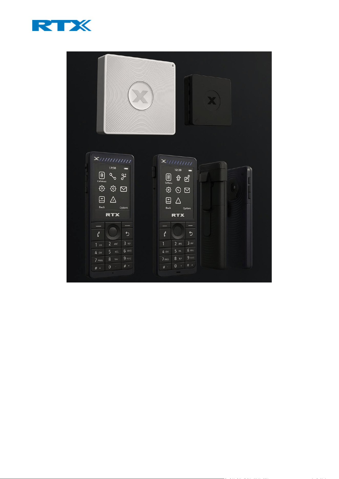
Figure 2 RTX VoIP products
2.3.1 Base stations
The base stations convert IP protocol to DECT protocol and transmit the traffic to and from the end-nodes
(i.e. wireless handsets) over a channel. They have 12 available channels.
In a dual/multi cell setup, each base station has:
• 8 channels that have associated DSP resources for media streams.
• 4 channels which are reserved for control signaling between IP base stations and the SIP/DECT end
nodes (or handsets).
In a dual and multi cell environment, the base stations are grouped into a cluster. Within the cluster, base
stations are synchronized to enable a seamless handover, when a user moves from one base station coverage
to another. The 4 control signaling channels are used to carry signals that enable a handset to initiate a
handover process.
In a multi cell environment, it is not necessary for base stations to communicate directly with each other in
the system. This means that a base station may only need to communicate with the next in the chain. It is
advisable for a base station to identify more than one base station to guarantee synchronization in the case
that one of the bases fails.
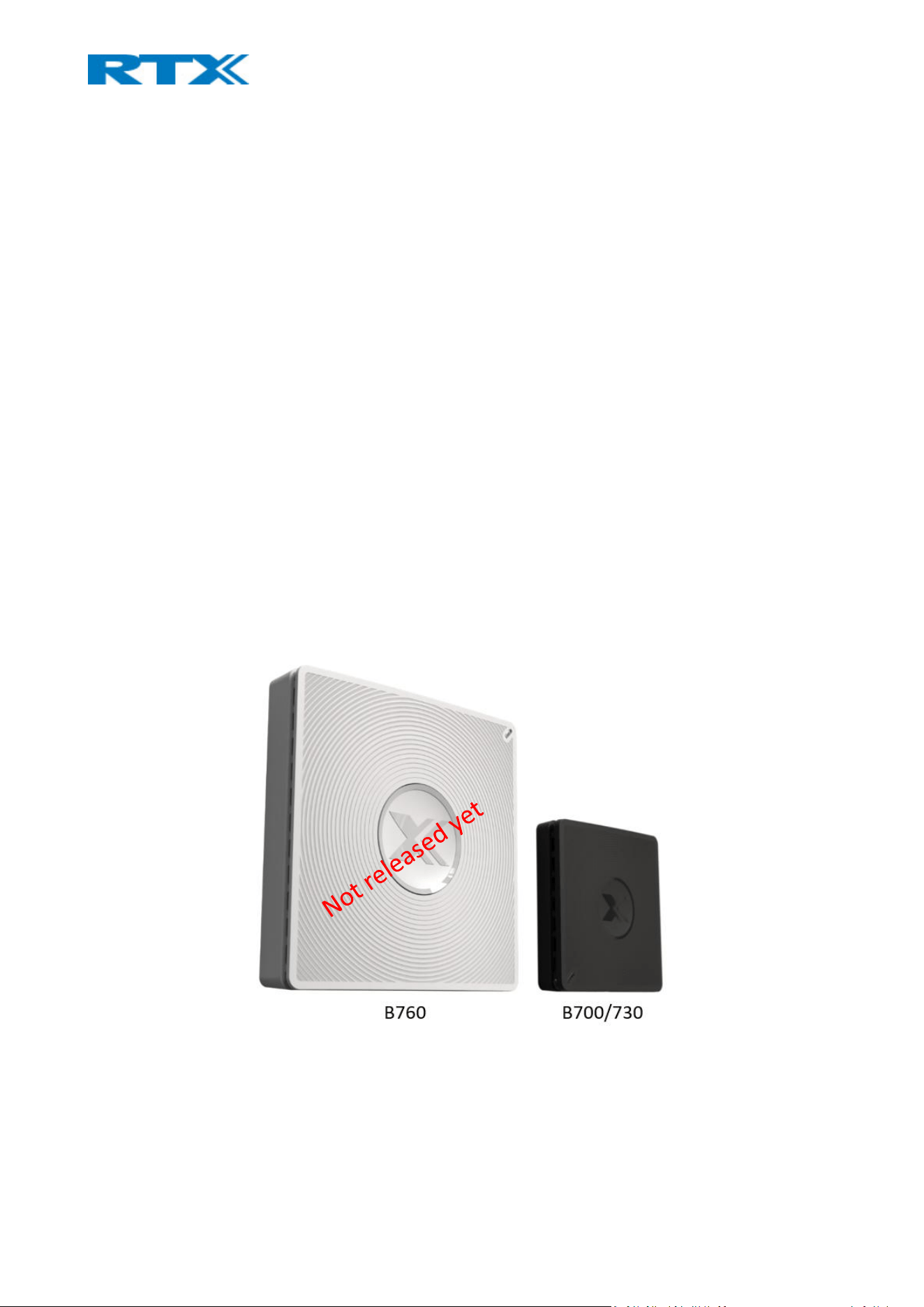
There are three types of base stations offered by RTX: B760 Multi cell and B700/730 Single/Dual cell (Fig.3).
Note: The model B760 is not released yet.
Figure 3 RTX base station models
The B760 base is a scalable multi cell IP DECT base station for Small, Medium and Large Enterprises. The multi
cell system offers a unique redundant solution that ensures the best up time. The system is scalable from 1
base and 40 users, up to 4000 bases and 16000 users. The scalability is achieved by used patent protect

technology. The system easily integrates towards a cloud solution that ensures easy maintenance, high
security, and flexibility.
The second type of base offering is B700/730, which is the Next Generation Single Cell base station. It can
easily be upgraded to a dual cell that extends range and call capacities. The dual cell uses the same patent-
protected technology as the B760 multi cell system. The dual cell offers 100% security and plug and play for
the second base.
Both base stations can be used in a standalone mode via the power cable (without PoE).
The main differences between the two devices can be seen in the table in Appendix 9.7 Calls Capacity.
* It does not matter if you are running Single cell or Dual cell setup, the maximum number of SIP registrations
for B700/730 is 40 (with a maximum of 20 handsets). On the contrary, the B760 allows having up to 40 SIP
registrations per base.
These numbers make it possible for different combinations of terminals with SIP extensions.
Every “SIP account” occupies one “extension instance”. However, as a terminal instance cannot exist without
a SIP instance, a terminal associated with a SIP account, occupies only one extension instance in total. A
terminal associated with two SIP accounts occupies two extension instances, etc. This means that in order to
have 40 SIP accounts, you can have the following combinations:
• 40 handsets, each with 1 line (i.e. 1 SIP account) – only for B760
• 20 handsets, each with 2 lines (i.e. 2 SIP accounts)
• 10 handsets, each with 4 lines (i.e. 4 SIP accounts)
• 8 handsets, each with 5 lines (i.e. 5 accounts)
B700/730 NOTE: When local call group mode is enabled, the maximum number of extensions is decreased to
30. However, the maximum number of handsets remains 20.
B760 NOTE: If there are over 150 base stations in a multi cell, the “Multicast” data sync should be used.
2.3.2 Handsets
A handset is a lightweight, ergonomic, and portable unit, compatible with Wideband Audio (G.722), DECT,
GAP standard and CAT-iq audio compliant. RTX’s handsets include a color display with graphical user interface
and can provide the user with most of the features available in a wired phone. In addition to this, they support
roaming and handover capabilities.
RTX offers several types of handsets with various characteristics (Fig.4).

Figure 4 RTX handset models
➢ RTX8830 is an IP65 handset intended for industrial, hospital and hotel use.
➢ RTX8630 is a mid-range handset intended for any work environment.
➢ RTX8631 is a ruggedized handset with Bluetooth intended for office use.
➢ RTX8632 is an IP65 handset with Bluetooth intended for industrial use.
➢ RTX8633 is an antibacterial IP65 handset with Bluetooth intended for hospital use.
➢ RTX8431/RTX8436 is an entry level handset intended for any work environment.
The main differences between the handsets can be seen in the table below. For more details, please refer to
the datasheets on www.rtx.dk
DESCRIPTION RTX8431 RTX8436 RTX8630 RTX8631 RTX8632 /
RTX8633
RTX8830
Display 1,77’’ TFT,
128x160
2" TFT,
176x220
2’’ TFT,
176x220
2’’ TFT,
240x320
2’’ TFT,
240x320
2’’ TFT,
176x220
Size (mm) 123 x 46 x 21 128 x 48 x
21
140 x 48 x
25
118 x 46 x 21 122 x 50 x 21 152 x 48 x 28
Weight
(including
batteries)
98g 110g 136g 86g 95g 175g
Talk time 22H(NB), 14H(WB) 18h(NB),
12h(WB)
17h(NB), 12h(WB)
Battery 1100 mAh Li-ion
Alarm Key No No No Yes Yes Yes
Bluetooth No No No Yes Yes Yes
Other 4 extra programmable keys RTX8633 has
antibacterial
coating
NOTE: From v730 supports Bluetooth 5.1 on handsets that have this feature.
2.3.3 Repeaters
Repeaters are devices which extend the DECT signal to ensure a wider DECT range for handling the calls.
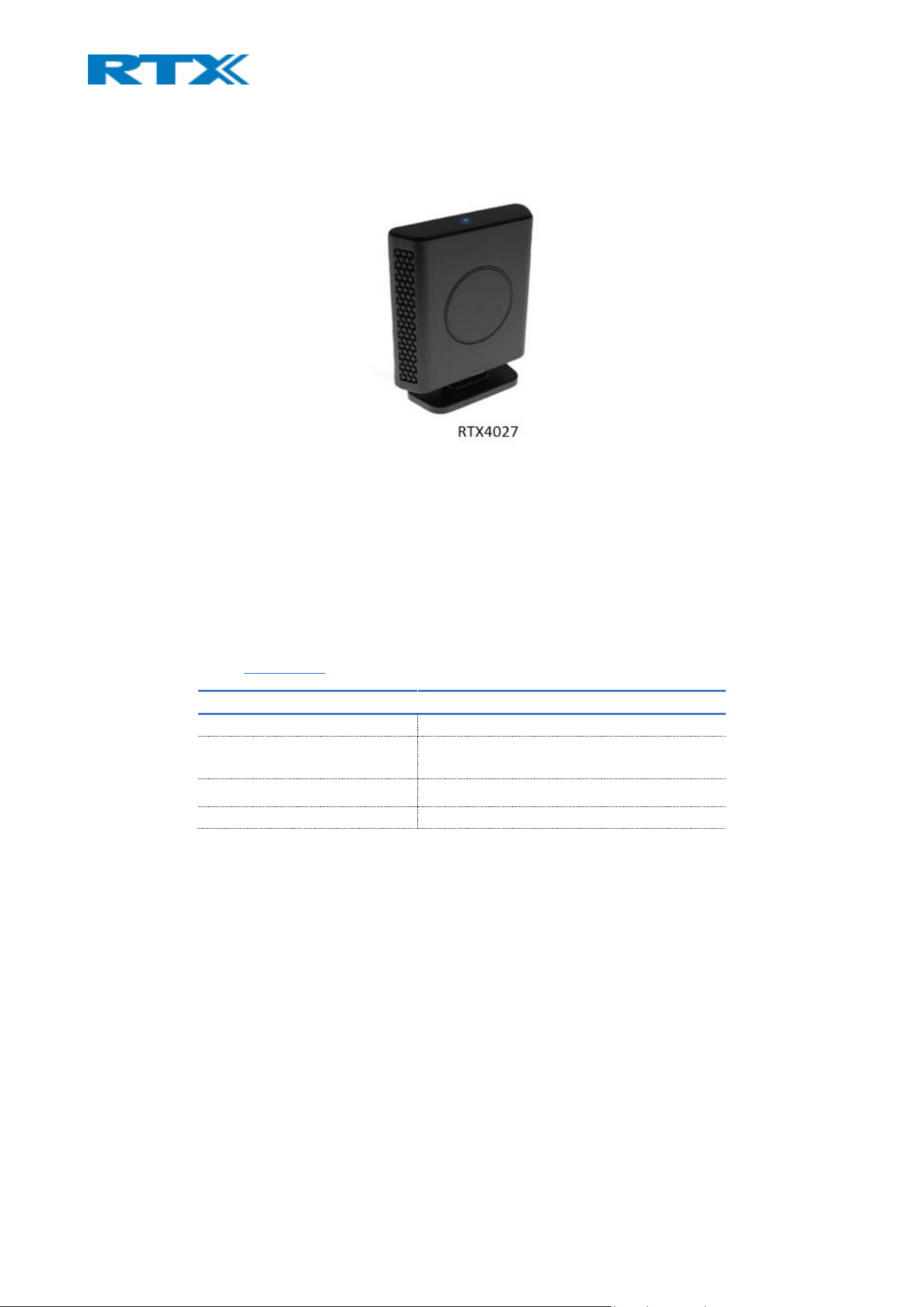
Currently, RTX offers RTX4027 repeater which ensures more coverage and range (Fig.5). This guarantees
perfect quality and interruption-free calls in large premises. Each repeater adds up to 50m indoor and 300m
outdoor of extra range. Combined with encrypted daisy chaining, this adds 150m indoor or 900m outdoor
range to a base. The RTX4027 is compatible with all RTX system solutions - extending range both indoor and
outdoor.
Figure 5 RTX repeater
Since the device has the same hardware overview as the B700/730 base station, the repeater can be
identified by the following characteristics:
• The repeater has a double lined blue symbol on the top of the device (Fig.5)
• The label at the back of the device
• The missing LAN port.
The main characteristics of the repeater can be seen in the table below. For more technical details, please
refer to RTX’s website www.rtx.dk
DESCRIPTION RTX4027
Size 120(W) x 35(D) x 135(H)mm
Coverage Up to 50m indoor and 300m outdoor
Receiver sensitivity: -92dBm
Antennas 2 internal omni-directional
Simultaneous call handling 2 (wide band) or 4 (narrow band)
2.4 User interface
The handsets and base stations provide the user with an easy-to-use digital interface. This section aims to
present the different user interfaces available on the devices.
2.4.1 Base station configuration interface
Both base station models come with the same user-friendly SME VoIP Configuration Interface. It is a web-
based administration platform used for configuring and programming the base station and relevant network
end-nodes (Fig.6). For example, handsets can be registered and de-registered from the system by using the
configuration interface. Furthermore, this web-based platform can be used as a setup tool for uploading
software/firmware to the base stations, repeaters and handsets. Moreover, it provides relevant system logs
that can be used by the administrator to help troubleshoot the system, if it faces unforeseen operational
issues.
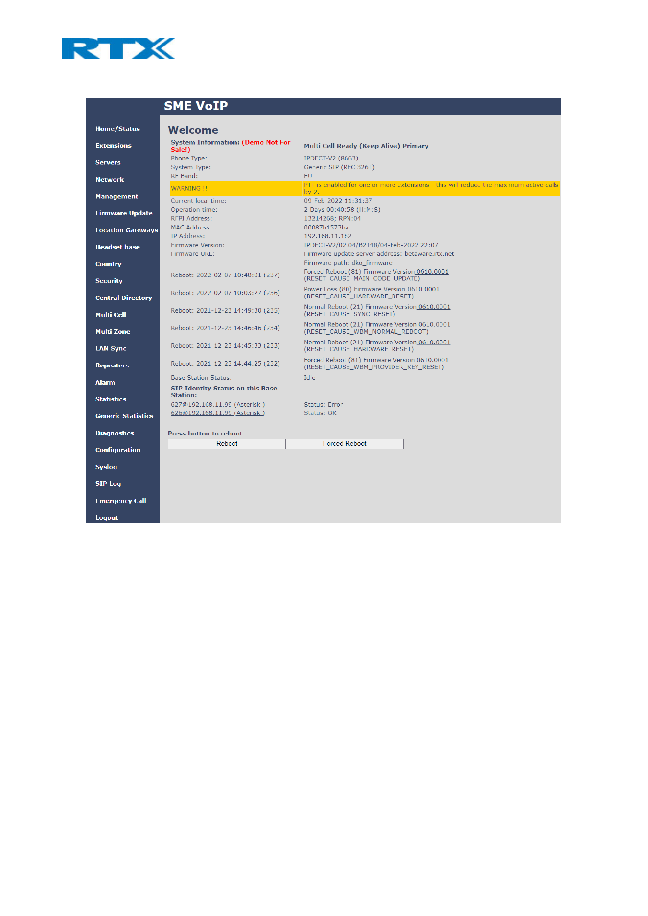
Figure 6 Base station's user interface
The web-based administration page is compatible with the following browsers:
• Chrome 68+
• Edge 42+
• Firefox 61+
• Safari 11.1.2+
The interface is accessed by typing the IP of the base station. On the left-hand side is the blue navigation
panel which contains links to different configuration menus. On the right-hand side is the view which lists all
the data and configuration parameters. The view changes according to the selected menu from the panel.
2.4.2 Handsets
All type of handsets have the same design, interface logic and icons. However, there are two types of user
interface – Classic and Modern MMI (Fig.7). The difference between the 2 MMIs is the interface outlook and
the design of the icons. It is up to the client to decide which user interface to integrate in the device. Please
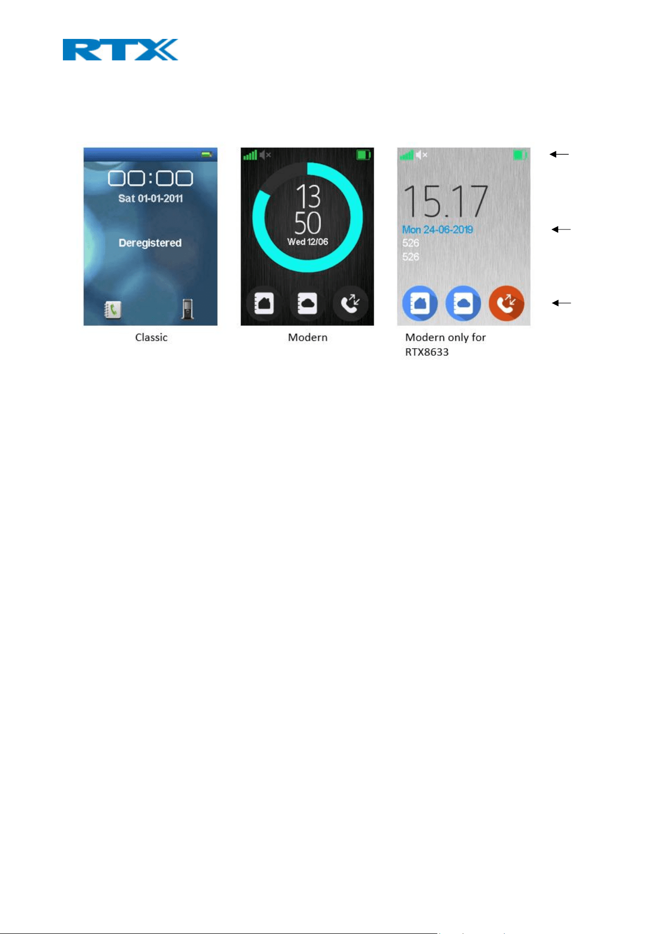
note, that the interface cannot be changed via the menu or a specific setting. The transition is only possible
with the use of the specific firmware file.
Figure 7 Handsets' user interface
2.4.3 Repeaters
The repeaters do not have a user interface.
Status bar
Date/Time
Softkey bar

3 Unboxing
Before unboxing, please examine the shipping package for evidence of physical damage. If there is a proof of
mishandling prior to opening, you must report it to the relevant support center of the regional representative
or operator. Furthermore, make sure that all relevant components are present in the package before
proceeding to the installation guide.
Damage inspection guide:
• Examine all relevant components for damage.
• Make a “defective on arrival – DOA” report or RMA to the operator. Do not move the shipping carton
until the operator has examined it. If possible, send pictures of the damage. The operator/regional
representative will initiate the necessary procedure to process the RMA. They will guide the network
administrator on how to return the damaged package, if necessary.
• If no damage is found, then unwrap all the components and dispose of empty package/carton(s) in
accordance with country specific environmental regulations.
The following sections present the contents of the package for each RTX device.
3.1 Base stations
Every shipped base unit package/box contains the following items:
B700 B730 B760
1x Base unit 1x Base unit 1x Base unit
2x Mounting screws and
2x Anchors
2x Mounting screws and
2x Anchors
2x Mounting screws and
2x Anchors
1x Ethernet cable 1x Ethernet cable 1m 1x Quick guide
1x Quick guide 1x Quick guide 1x Safety sheet
1x Safety sheet 1x Safety sheet
1x Power adaptor
NOTE: The following information is valid only for B700/730 base station:
The DC adaptor type is as listed below:
Manufacturer DC adaptor plug type
S005CAV0500100 SMPS 5V/1A USB-A EU-P
3.2 Handsets
Every shipped handset unit package/box contains the following items:
RTX8431/RTX8436 RTX8630 – RTX8633 RTX8830
1x Handset unit 1x Handset unit 1x Handset unit
1x Battery cover 1x Battery cover 1x Battery
1x Handset belt clip 1x Handset belt clip 1x Handset belt clip
1x Charger 1x Charger 1x Charger
1x A/C adaptor 1x A/C adaptor 1x A/C adaptor
1x Battery 1x Battery 1x Belt clip cover

1x Plastic cover to replace the
belt clip
1x Pull cord cover
1x Swirl for belt clip
2x Mounting screws
3.3 Repeaters
Every shipped repeater package/box contains the following items:
RTX4027
1x Power supply
1x Repeater
1x table stand
1x Safety sheet
4 Hardware characteristics
The following sections aim to introduce you to the hardware outlook and features of the VoIP products.
4.1 Base stations
4.1.1 LED indicator
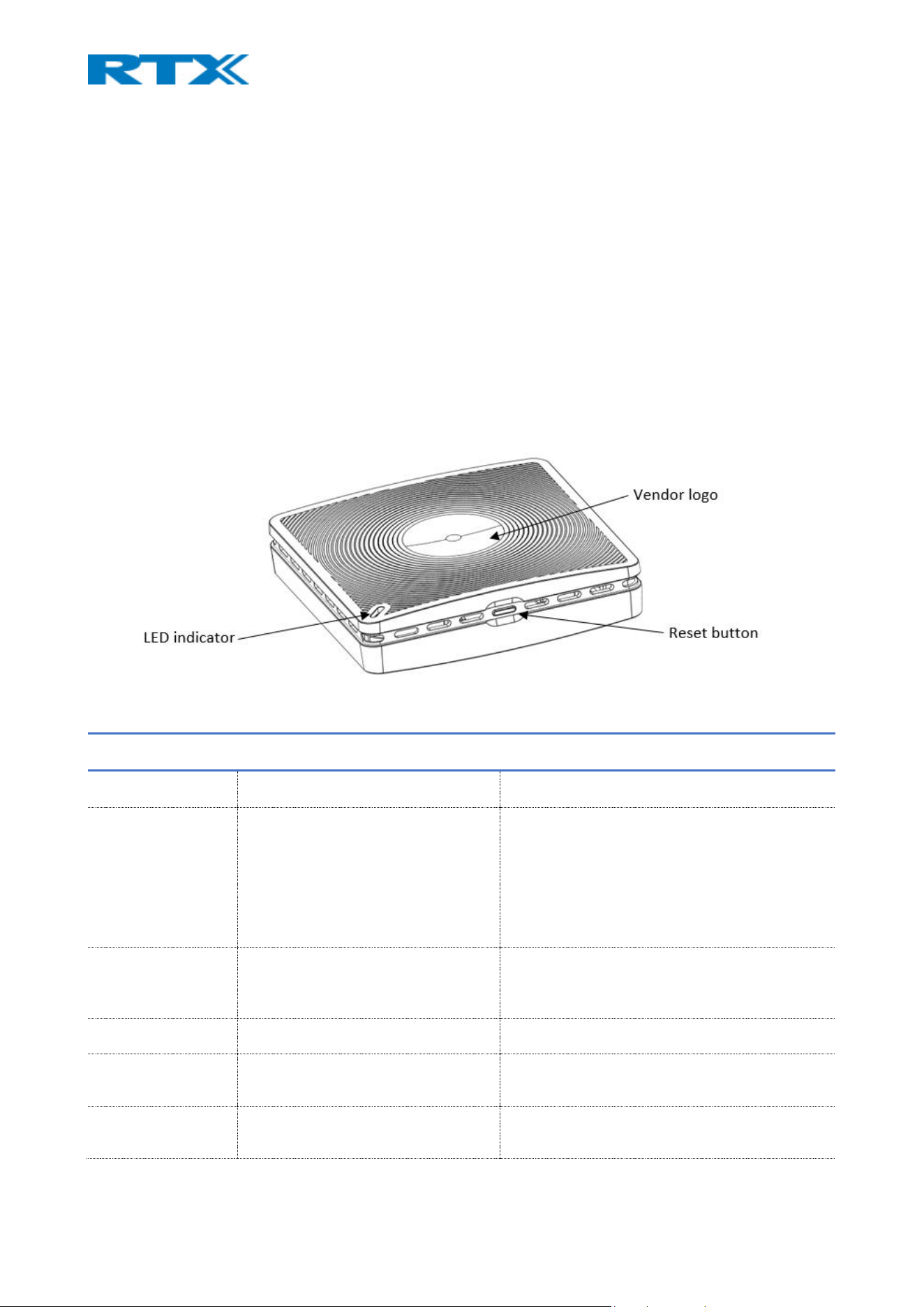
Both base stations (B700/730 and B760) have an LED indicator at the front-end panel (Fig.8). It is used to
signal different functional states of the base units and occasionally of the overall network. There are two
blink patterns that indicate the different states:
• Blink pattern 1: 800 ms on, 400 ms off
• Blink pattern 2: 400 ms on, 400 ms off
The indicator is off when a base unit is not powered on.
Figure 8 Base hardware characteristics (B700/730)
LED COLOR INDICATION STATE
UNLIT Off No power in unit
RED Steady on Error condition
/Unrecoverable error during early boot
/Starting factory reset
/Multicell signal strength is critical
RED Blink pattern 1 /Network down
/SIP (de)registrations failure
RED Blink pattern 2 802.1x Authentication Failed
GREEN Steady on Normal operation
GREEN Blink pattern 1 Multicell is in search mode

ORANGE Steady on /Starting base reboot
/Multicell signal strength is low
ORANGE Blink pattern 1 Application is starting
4.1.2 Reset button
In addition to the hardware characteristics, the base stations have a reset button which allows the user to
restart or reset the device. On both bases the button is placed below the main unit (Fig.8). Alternatively, the
bases can be reset from the web SME Configuration Interface. Furthermore, unplugging and plugging the
Ethernet cable back to the PoE port of the base, also resets the base unit. However, we do not recommend
using this reset method.
4.2 Handsets
There are some minor hardware differences between the devices, even though all handsets have a similar
design. The following list presents an overview of RTX8631 handset, which includes all the main hardware
features for the handsets.
NOTE: RTX8431/RTX8436 has 4 extra programmable keys, also called Function keys, placed below the
original keypad
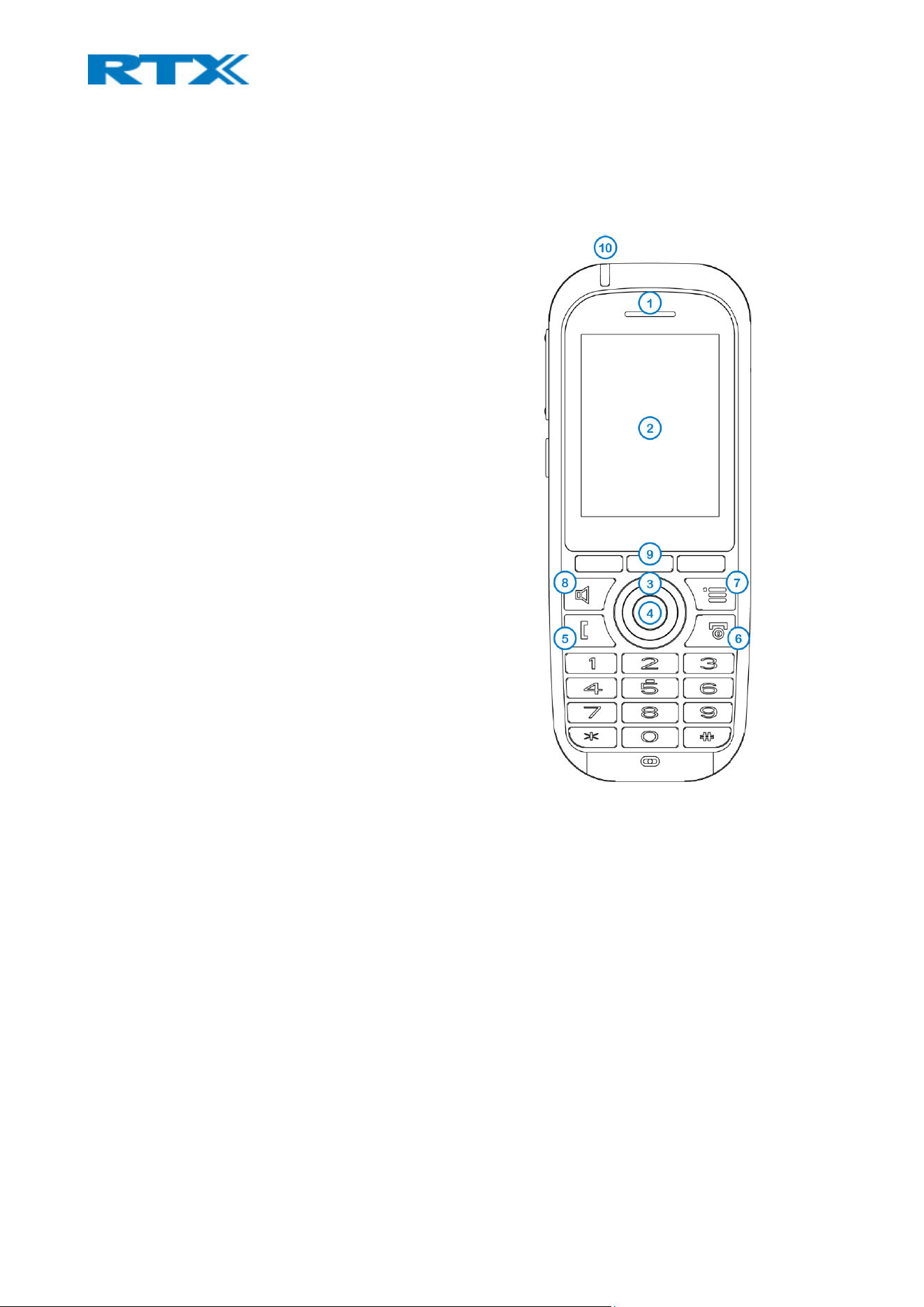
4.2.1 General overview
1. Earpiece Speaker
2. Screen
3. Navigation keys
Up/Down/Right/left
4. Selection key (Center of Navigation keys)
Use to confirm/select an option.
5. Off-hook key
Answer a call;
Use as a shortcut to the Call list.
6. On-hook key
End a call;Return to the previous menu;
Switch the handset on/off by long press.
7. Activity Menu Key
Enter the main menu of the handset.
8. Speaker Key
Enable/Disable speaker mode during a call.
NOTE: If enabled during a call, the speaker key will light up in
red and the sound will come from the speaker on the back of
the handset
9. 3 Softkeys
Used for different commands in the various menus of
the handset, which change according to what is
displayed on the screen.
10. LED
Indicates incoming call, missed call, messaging, low
battery and charging.
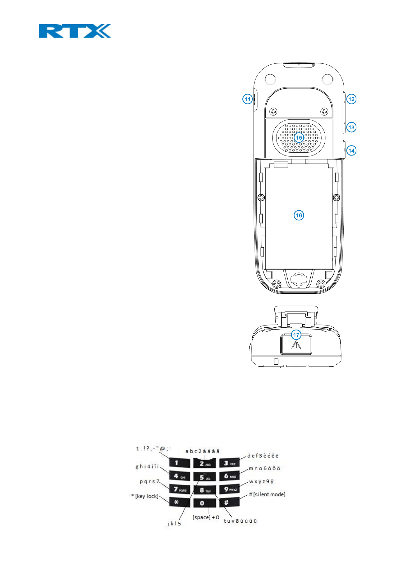
11. Headset connector (3.5mm)
A slot used for connecting a headset. The connector is
protected against dust by the headset connector
cover.
12. Volume Up Key (Side Key)
Increase the volume during a call.
13. Volume Down Key (Side Key)
Decrease the volume during a call.
NOTE: The volume buttons are used to control the volume
when using the earpiece, a headset, and the loudspeaker. The
lowest volume level will not mute the handset.
14. Mute Key (Side Key) / Push-to-talk (PTT) key
Turn off the microphone during a call, so that the
counterpart cannot hear you
If the handset is in idle and the button is pressed, it
will activate the PTT function.
NOTE: For more details on the PTT feature, please refer to
7.3.4.19. Push to Talk
15. External Speaker
Used when speaker mode is enabled in a call.
16. Battery
17. Alarm Key
Supported only by RTX8631-RTX8633, RTX8830
4.2.2 Keypad
The sketch below illustrates the available characters on the handset’s keypad (Fig.9). Depending on the
selected menu language, other characters can be available. Therefore, the character order can differ from
the one below.
Figure 9 Handset keypad

NOTE: Any key from “2” – “9” can be set as a speed dial
key - a shortcut to calling any contact in the contact list, or in the F-Key list. A long press on any of these keys,
while the handset is in idle, will call the assigned contact. For additional information on this feature refer to
7.3.1 Contacts.
4.2.2.1 Number input mode
When in idle, a short key press enters the digits “0” – “9” and the characters “*” and “#”.
A long key press on “0” generates a “+”.
4.2.2.2 Text input mode
When writing a text, a short press on keys “0” – “9” displays the first available character on that specific key.
By pressing the “*” key it is possible to change the letter input to upper/lower case or only a numeric value
(Abc, abc, ABC, or 123).
Use the “0” key to add a space in the text.
4.2.2.3 Key lock
The keypad can be locked/unlocked by long pressing the “*” key in idle. This feature can prevent accidentally
pressing keys and making a call.
NOTE: It is possible to answer/reject an incoming call while the keypad is locked
4.2.2.4 Silent mode
The silent mode feature can be activated/deactivated by long pressing the “#” key in idle. When enabled, the
handset will turn to silent mode and a “Sound Off” icon will be displayed in the status bar.
NOTE: When this mode is enabled, it is possible to switch on/off the vibrator on the handset in Settings >
Audio Settings > Vibrator (refer to 7.3.4.1 Audio settings for further information). Please note, that all other
audio settings will be greyed out while the handset is in silent mode.
4.3 Repeaters
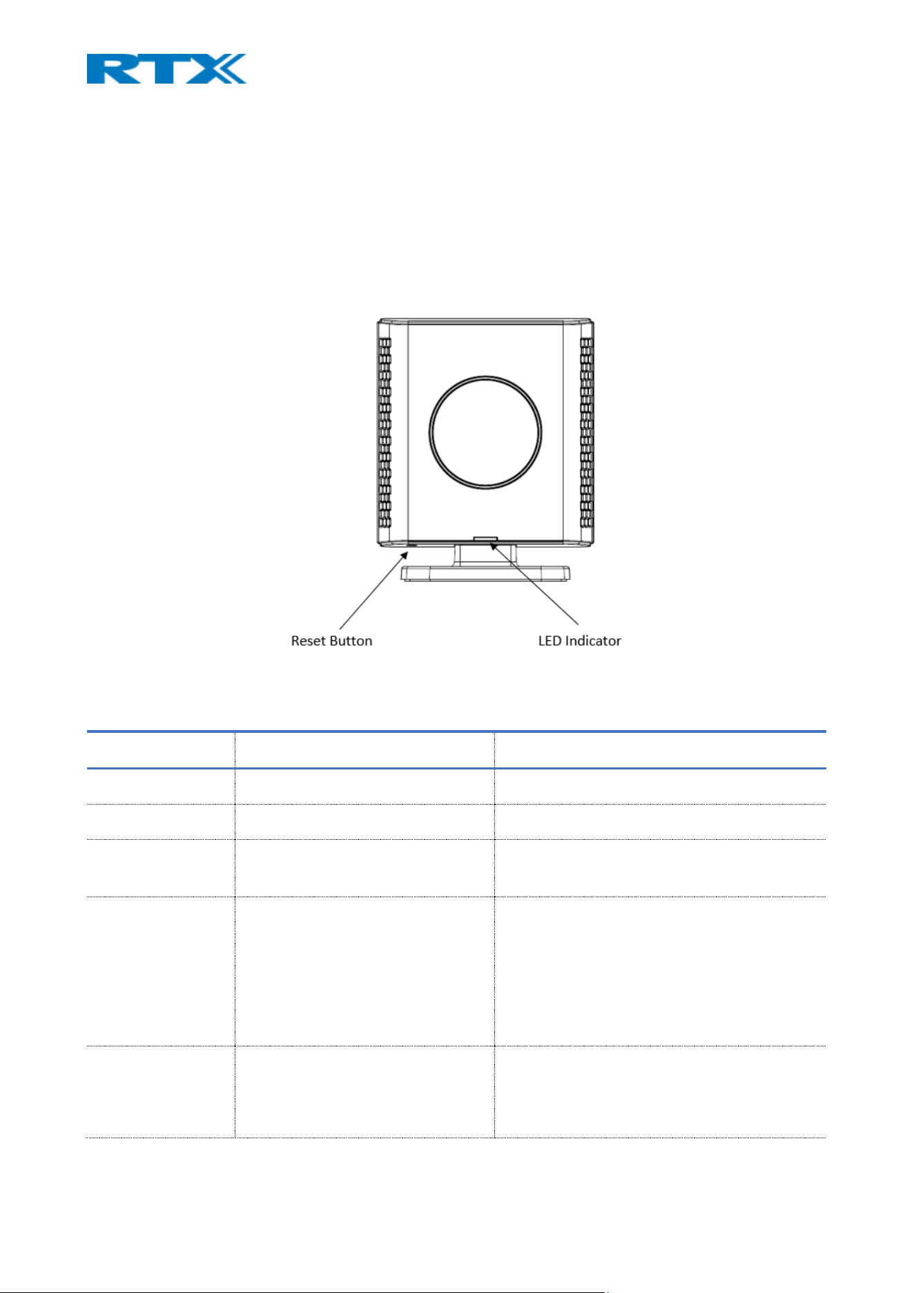
Similar to the base stations, the repeater also has an LED indicator and a reset button.
4.3.1 LED indicator
The LED indicator is off when a repeater is not powered on. The figure below (Fig.10) illustrates the location
of the LED on the repeater.
Figure 10 Repeater hardware characteristics
The following table provides more details about the different LED states.
LED COLOR INDICATION STATE
UNLIT Off Power Off
GREEN Slow flash Unlocked, searching for a base station
GREEN Double flash Registering procedure. Searching for an open
base station to register/subscribe to it.
GREEN Steady on Locked to a base station and ready to be
used;
/Ethernet connection available;
/Normal operation with good RSSI equal to or
better than -75dBm)
RED n Flash n handset using the repeater
/Ethernet connection not available or
repeater registration failed

RED Steady on Error condition; Unacceptable RSSI below -
90dBm; Critical error
/Registration procedure timed out after 5
min.
/When the reset key is long pressed, the LED
will light up in 2 sec. to indicate that releasing
the key will delete the registration. LED turns
off after 4 more sec.
ORANGE Steady on Normal operation with pure RSSI between -
75dBm and -90dBm
RED/GREEN Flashing Red/Green Active call under the coverage of the
repeater
/Recovery mode – repeater is locked to a
base station/repeater without repeater mode
activated.
/Sync. Source base station/repeater not
found (Manual mode).
/Timeout during RPN allocation due to busy
base station/repeater.
4.3.2 Reset button
Similar to the base stations’ hardware, the reset button of the repeater is placed below the main unit. It has
the following functionalities:
BUTTON PRESSS ACTION
00s < x < 02s Nothing
02s < x < 06s Delete registration.
Old registration is deleted and a new registration
procedure has started.
18s < x < 60s Enable/disable repeater monitor beep tone which is
heard in the handset during a call (when it is locked to a
repeater). This is used for testing handover and calls.
60s < x < XXs Nothing
5 Device installation
5.1 Base stations
Before installing the base stations, please first determine the best location that will provide an optimal
coverage, by considering the construction of the building, architecture and choice of building materials. Next,
proceed to the following sections to get an overview of the mounting and signaling details of the devices.
5.1.1 Mounting
Mount the devices on a wall to cover range between 50 – 300 meters (i.e. 164 to 984 feet), depending on
obstacles like walls, doors, etc. Mount them as high as possible (min. 2 meters) to clear all nearby objects
(e.g. office cubicles and cabinets, etc.). Make sure that when you fix the base stations with screws, the screws
do not touch the PCB on the unit. Furthermore, avoid all contact with any high voltage lines.
Note: B700/730 is not designed for outdoor use.
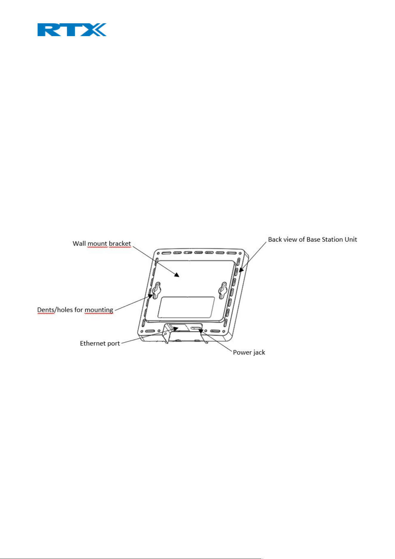
The images below illustrate the device installation characteristics for both B700/730 (Fig.11) and B760
(Fig.12) base stations.
Figure 11 B700/730 and B760 installation characteristics
When connecting the devices please follow the guidelines:
1. The device is to be connected only to networks without routing to the outside plant.
2. The device is connected to a network through a standalone networking device such as a network switch
or router... etc. located in an indoor environment.
3. Only trained and qualified personnel should be allowed to install, replace, or service this equipment.
5.1.1.1 B760 base
The B760 base station supports both horizontal and vertical signaling. This means that you should not follow
any positioning guidelines since it can transmit both ways. The antenna radiation pattern can be seen on the
figure below (Fig.13) where Antenna 0 is the green marking with max power 23,25 dBm and antenna 1 is the
red pattern with max power 22.45 dBm.
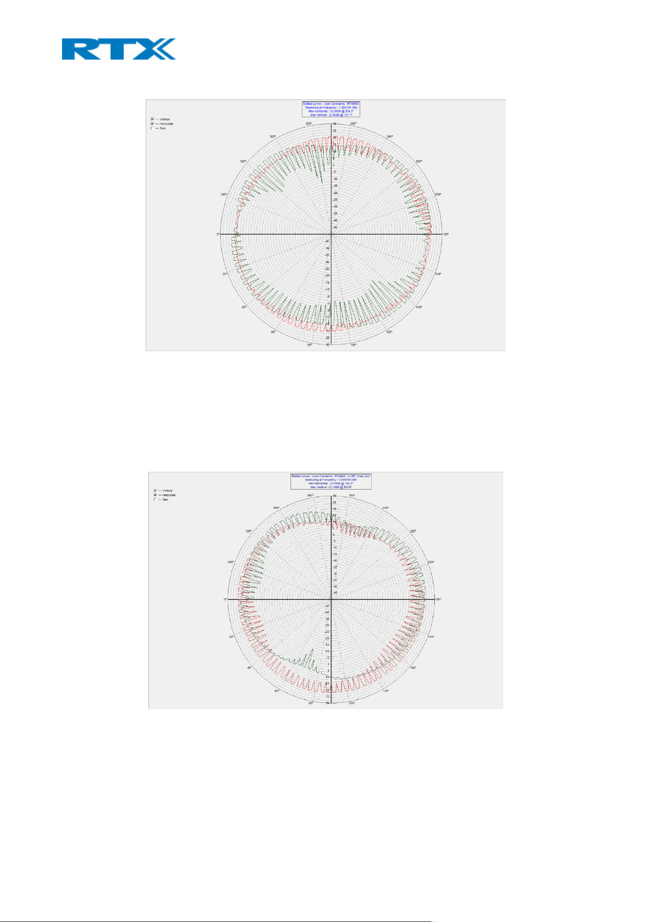
Figure 12 B760 antenna pattern
5.1.1.2 B700/730 base
The B700/730 base station also supports both horizontal and vertical signaling, meaning that you should not
follow any positioning guidelines (as it can transmit both ways). The antenna radiation pattern can be seen
on the figure below (Fig.14) where Antenna 0 is the green marking with max power 23,19 dBm and antenna
1 is the red pattern with max power 22.92 dBm.
Figure 13 B700/730 antenna pattern
Since the screws and anchors are not included in the B700/730 packaging, you will have to provide your own
two pieces of screws M3.5 x 31mm. The distance between them is 70mm (Fig.15).

Figure 14 B700/730 screws and anchors
5.2 Handsets
Before using the handset, you should be aware of the following precautions.
5.2.1 Handset battery
The handsets use Li-ion 3.7V 1100mAH 4.1Wh batteries to operate. Please, be aware of the following:
• Never dispose a battery in fire, otherwise it will explode. Instead, it must be delivered to a recycling
company.
• Never replace the batteries in potentially explosive environments, e.g., close to inflammable
liquids/gases.
• ONLY use approved batteries and chargers from the vendor or operator.
• Do not disassemble, customize, or short circuit the battery.
5.2.2 Handset charger
Each handset is charged using a handset charger. The charger is a compact desktop unit, designed to charge
and automatically maintain the correct battery charge levels and voltage. The handset charger is powered by
AC supply from 110-240VAC that supplies 5.5VDC at 600mA. When charging the battery for the first time, it
is necessary to leave the handset in the charger for at least 10 hours before the battery is fully charged, and
the handset is ready to be used.
For correct charging, ensure that the room temperature is between 0°C and 25°C / 32°F and 77°F. Do not
place the handset in direct sunlight. The battery has a built-in heat sensor which will cause the battery to
stop charging if its temperature is too high.
If the handset is powered off when placed in the charger, the handset will turn on and display (shortly) the
charging message “Charger connected”. After a while, the display backlight will dim and then turn off.
Anyway, the handset will be available for incoming calls, messages, etc.
If the handset is turned on when placed in the charger, the display will show (shortly) the charging message
“Charger connected”. After a while, the display backlight will first dim and then turn off, unless “Idle Screen
Saver” is enabled.
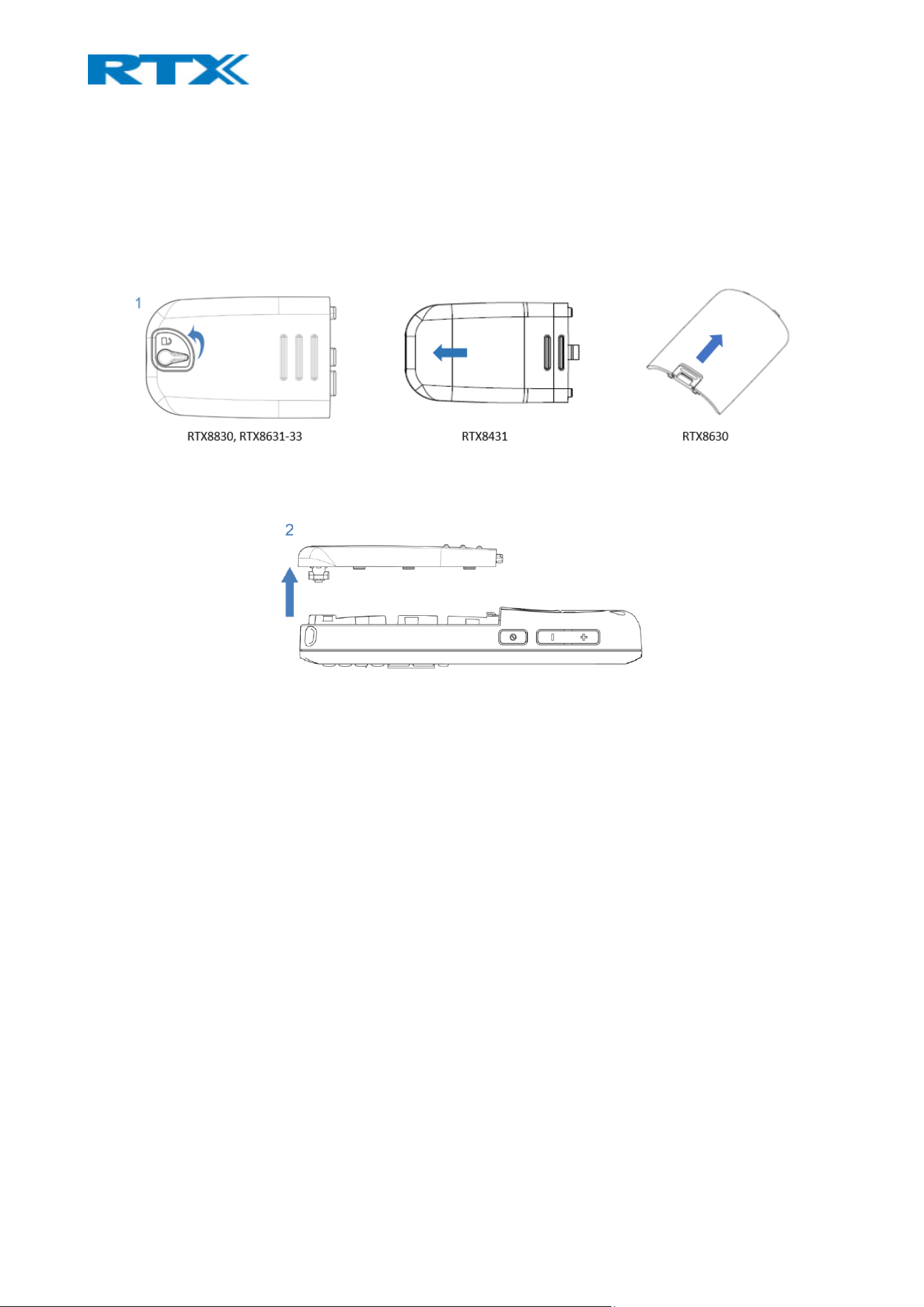
Each handset comes with a battery which is already placed in the device. However, you need to activate the
battery by removing the plastic foil. To access the battery slot, you first need to open the back cover.
Depending on the handset type, the back cover can be opened in different ways (Fig.16). Afterwards, you
need to remove the battery followed by the plastic foil. Do not pull the plastic foil out without removing the
battery, that might damage the charging pins. After that you can put the battery and the cover back in place
and charge your handset. (Fig.17).
Figure 15 Open the back cover from the handsets.
Figure 16 Removing the back cover from the handsets.
On the battery slot of each handset, you can find a label with the serial number (S/N) and IPEI/IPUI number
of the device. This information can be also seen on the packaging label of the handsets.
5.3 Repeaters
Before installing the repeater, first determine the best location that will provide an optimal coverage, by
considering the construction of the building, architecture, and choice of building materials.
The RTX4027 repeater is similar to the B700/730 base station in terms of signaling and mounting. Therefore,
for more details concerning the installation of the device, please see 5.1.1.2 B700/730 base.
Note: RTX4027 is not designed for outdoor use.

6 Access to device
The following chapter aims to help you access the base station and handsets. The repeater is excluded from
this section, as it does not have an interface.
6.1 Base station
6.1.1 Base station IP address
To enter the user interface of the base station, you first need to connect the base to a private network (via
standard Ethernet cable CAT-5). Afterwards, you need to find the device’s IP and type it in your internet
browser. There are 2 ways of finding the IP address of the base – using the handset or the browser.
6.1.1.1 Using the handset
The handset has an “IP search” feature, which allows the user to view the IP address of the bases in range of
the handset. To use this feature, please follow the steps below:
Step 1 Handset in idle
Step 2 Press the Menu key
Step 3 Type *47*
The handset will now enter scanning mode and will listen for signals from the nearest base stations.
Depending on the amount of powered on bases and the distance to them, it can take up to a few minutes to
find a device. As soon as a base is found, the handset will display the MAC address of the base, together with
its IP address (Fig.18). You can use the navigation keys on the handset to scroll up and down along the list of
found devices.
Figure 17 IP search menu
6.1.1.2 Using the browser
To find the IP address of the base via the browser, please follow the steps below:
Step 1 Open any standard browser and enter the below address, where <MAC-Address-Base-
Station> is the MAC address of the device
http://ipdect<MAC-Address-Base-Station>
Example: http://ipdect00087B00AA10
By typing this information, the HTTP Web Server page will be retrieved from the base station with hardware
address <MAC-Address-Base-Station> (in this case 00087B00AA10).
6.1.2 Login to base
To access the login window of the base, please follow the steps below:
Step 1 Connect the base station to a private network and find the IP address of the device (see
previous section 6.1.1 Base station IP address)
a. If the handset method is used, open a browser and type in the IP address
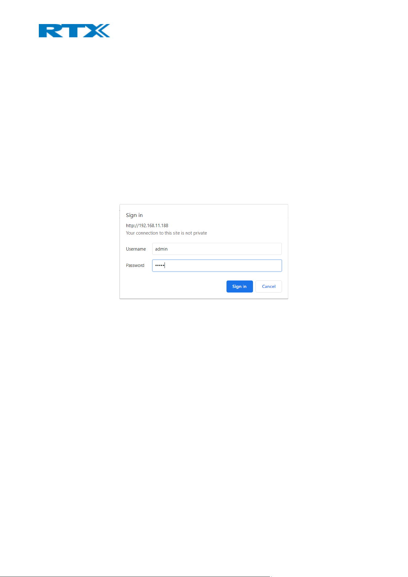
Step 2 On the Login page, enter your authentication credentials (i.e. username and password)
(Fig.19). By default, the username and password are admin/admin. Press OK.
NOTE: In case secure web server is enabled the server automatically redirects from http:// to Error!
Hyperlink reference not valid. in the browser address line.
Figure 18 Login page of the base
Step 3 Once you have been authenticated, the browser will display the front end of the SME VoIP
Configuration Interface (Fig.6). The front page will show relevant information of the base station.
6.2 Handset
To get access to the handset, simply insert the battery and power on the device by long pressing the hook-
on button. The display will light up and the handset will be ready for use.
7 Software characteristics
The following chapter will provide you with information about the features and different functionalities
available in the software, for both the bases and the handsets. Since the repeater does not have any user
interface and is not meant to be manually setup by the user, the device is not included in this chapter.
7.1 Base station
The SME VoIP Configuration Interface, also known as SME VoIP Administration page, is the main interface
through which the system is managed and debugged. The SME VoIP Administration page is an in-built, HTTP
Web Server service residing in each base station. It is a user-friendly interface, making it easy to handle even
to a first-time user.
NOTE: Enabling secure web is not possible. For secure configuration, use secure provisioning (refer to 7.1.22
Configuration)
This subchapter seeks to define various variables/parameters, by going through each of the available menus
and settings on the base station. These settings can be configured in 2 ways – via the web interface or via
provisioning (refer to 7.1.22 Configuration for further details). Certain pages (Extensions, Repeaters, Location
gateways and Multi/Dual cell) support an auto refresh feature, which allows the user to easily monitor the
system. The pages are automatically re-freshed every 5 seconds.
IMPORTANT: The guide is based on the full feature set of B760. Therefore, the settings, which are not
supported by B700/730, will be clearly stated (for ex. NOTE: This feature is not supported by B700/730)
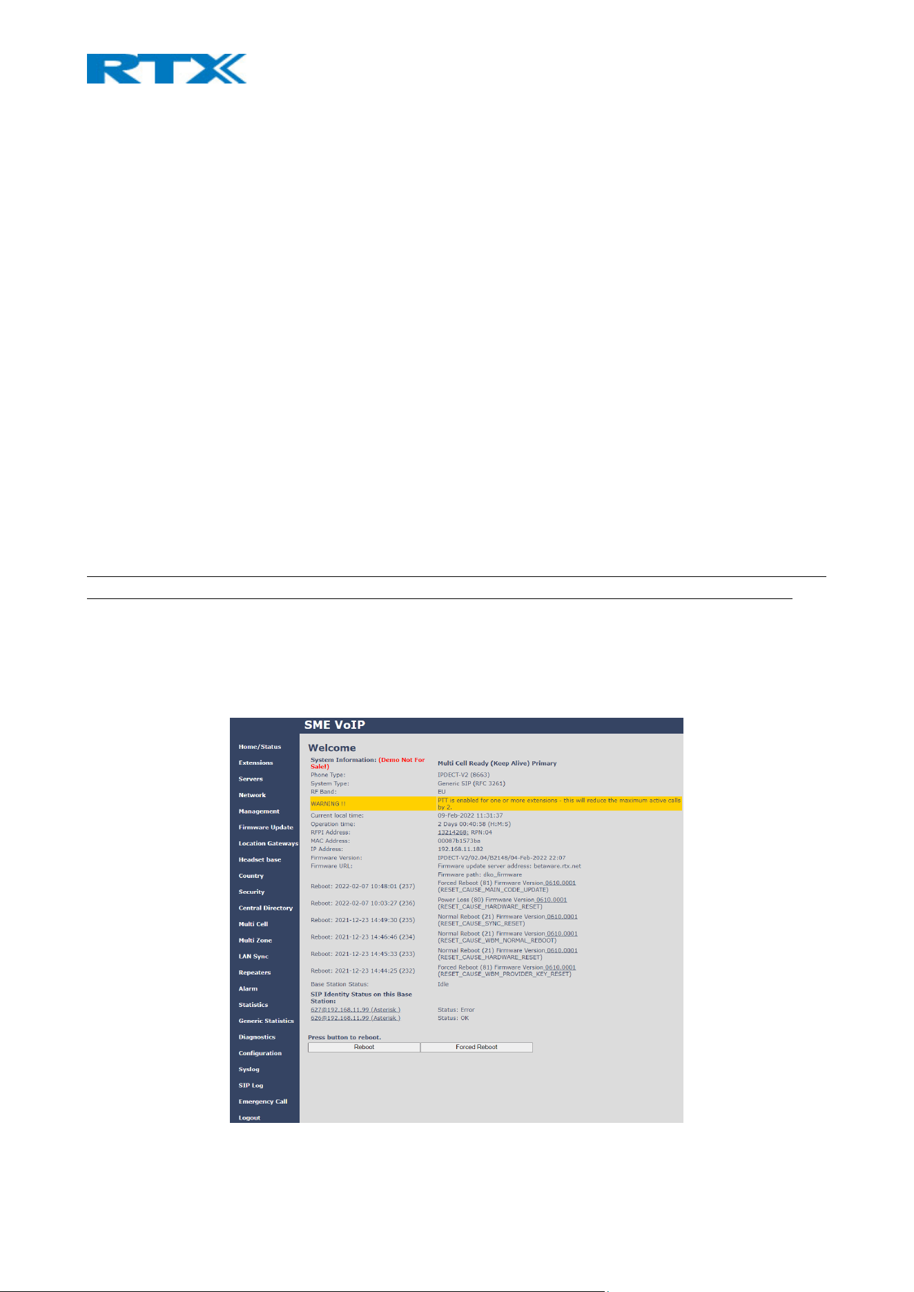
7.1.1 Web navigation
The screenshot below (Fig.20) illustrates the front page of the SME VoIP Administration Interface of the base
station. The various menus, seen on the left-handed navigation panel, are briefly presented in the following
table.
Figure 19 SME VoIP Administration Interface

FEATURE DESCRIPTION
HOME/STATUS This is the front end of the base station’s HTTP web interface. This page shows a summary
of the current operating condition and settings of the base station and handset(s).
EXTENSIONS Administration of extensions and handsets in the system
SERVERS On this page, the user can define which SIP/NAT server the network should connect to.
NETWORK Provides the user with the main network settings, such as:
NAT settings: allows configuration of features for resolving the Network Address
Translation. These features enable interoperability with most types of routers.
IP settings: allows setting dynamic (DHCP) or static IP address for your SME network
Virtual LAN: allows specifying the Virtual LAN
MANAGEMENT Defines additional settings such as the Configuration server address, Management transfer
protocol, Text messaging and sizes of logs/traces that should be catalogued in the system.
FIRMWARE
UPDATE
Remote firmware update (HTTP(s)/TFTP) settings of base stations and handsets.
LOCATION
GATEWAYS
Administration of Location Gateways
NOTE: The Location gateway feature must be enabled via the Management page for this
menu to appear on the navigation panel (refer to 7.1.7.8 Location gateway)
HEADSET BASE Administration of headset bases
NOTE: The Headset base feature must be enabled via the Management page for this menu
to appear on the navigation panel (refer to 7.1.7.9 Headset base)
COUNTRY Allows specifying the country/territory where the SME network is located. Configuring
these settings ensure that your system is working properly.
NOTE: The base language and country settings are independent of each other
Time settings:
The user can configure the Time server to always have their base synched with the exact
time. The time servers must deliver the time to conform to the Network Time Protocol
(NTP). Handsets are synchronised to this time. Base units synchronise to the master using
the Time server.
SECURITY The users can administrate certificates and create account credentials with which they can
log in or log out of the embedded HTTP web server.
CENTRAL
DIRECTORY
Provides an interface to a common directory load of up to 3000 entries using *csv format,
or to a configuration of an LDAP directory.
NOTE: LDAP and central directory cannot operate at the same time
MULTI CELL Enables the user to create a chain of base stations (a multi cell environment). Make sure
the system ID for the relevant base stations is the same, otherwise the multi cell feature
will not work.
NOTE: For B700/730, this menu is displayed as Dual cell and allows you to create a chain of
2 bases
MULTI ZONE Administration and configuration of the zones in a Multi zone setup
NOTE: This feature is not supported by B700/730
LAN SYNC Administration and configuration of network synchronization between the bases
NOTE: This feature is not supported by B700/730
REPEATERS Administration and configuration of repeaters in the system
ALARM Administration and configuration of the alarm settings on the system. This controls the
settings for alarms that can be sent to the handsets. This feature is only available on certain
types of handsets.

STATISTICS Overview of the system and call statistics
GENERIC
STATISTICS
Overview of general parameter statistics of the system
DIAGNOSTICS Overview of base stations and extensions diagnostics
CONFIGURATION Displays the detailed and complete SME system settings for the base station
SYSLOG Reports overall network related events or logs (only live feed is shown)
SIP LOG Reports SIP related logs
EMERGENCY CALL Administration and configuration of emergency numbers
LOGOUT Logout of the web interface
NOTE: Only one admin session is allowed at a time. If one admin is successfully logged in, the other admin
session is automatically logged out.
NOTE: After 10 failed logins within 5 min, all requests for authentication for the next 5minutes are rejected.
7.1.2 Home/Status
This section presents and describes the available parameters on the Home/Status page of the SME VoIP
Administration Interface (Fig.20).
PARAMETER DESCRIPTION
SYSTEM INFORMATION The current multi (dual) cell state of the specific base. It can be as follows:
Keep-Alive = Normal operation
Active = Sending sync data
Passive = Receiving data
Active – Primary = Base is sending data, and it is the primary
Passive – Secondary = Secondary Base receiving data.
PHONE TYPE Always IPDECT
SYSTEM TYPE The customer configuration for the specific base
RF BAND The RF band setting for the specific base.
The parameter is defined in production and relates to the radio approvals present
on the label of the base.
CURRENT LOCAL TIME The local time of the specific base
OPERATION TIME Operation time for the base since the last reboot
RFPI-ADDRESS The RFPI address of the specific base
MAC-ADDRESS The MAC address of the specific base
IP-ADDRESS The IP address of the specific base
FIRMWARE VERSION The firmware version of the specific base
FIRMWARE URL Firmware update server address and firmware path to the file on the server
REBOOT Displays information about the last reboots of the base station
BASE STATION STATUS Displays the status of the base
Idle: When there are no calls on the base
In use: When there are active calls on the base
SIP IDENTITY STATUS List of extensions present on this base station.
Format: “extension”@“this base’s IP address”(“server name”) followed by their
status to the right. Below are listed possible status outputs:
OK: Handset is ok
SIP Error: SIP registration error
REBOOT Reboot the base after all connections are terminated (such as active calls,
directory access, active firmware update, etc.)
FORCED REBOOT Reboot immediately.
7.1.3 Extensions
This section describes the different parameters available when creating extensions for the handsets.
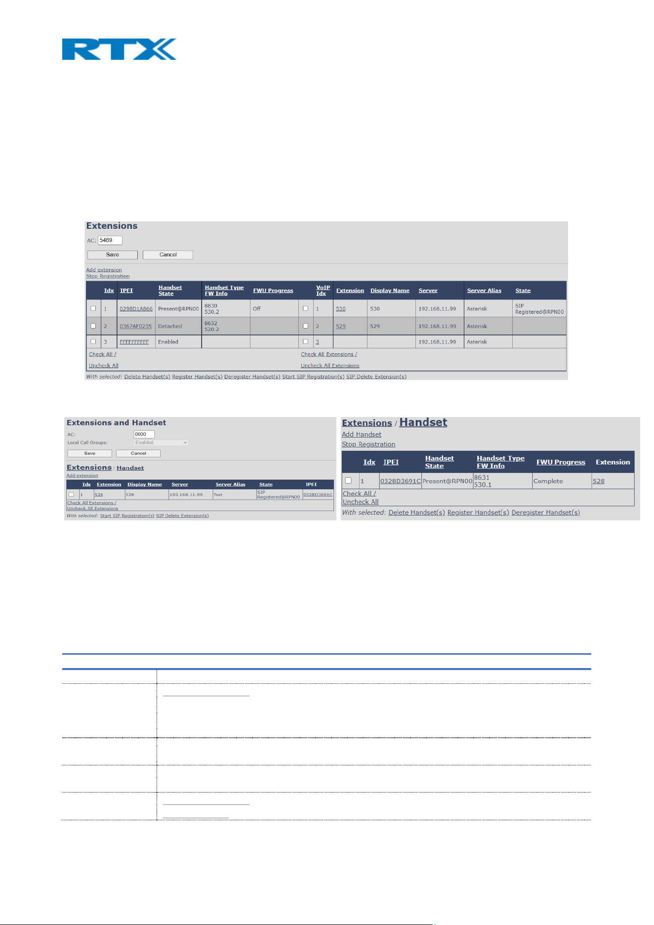
Depending on the base (B760 or B700/730), the Extensions page has a different view. The B760 shares one
page for both handsets and extensions (Fig.21), whereas the B700/730 provides 2 separate views for the
extensions and devices via the Extensions / Handset links (Fig.22) This is because 9431 has the feature Call
Group available, that is not present on 8663. However, there is no other significant differences in the settings
between both bases.
Figure 20 Extensions page view on B760
Figure 21 Extensions page view on B700/730
The Extensions page contains an extension/handset list and top/sub- menus. The extension/handset list is
used to provide information about the existing devices and allow the control of paring and removing handsets
from the system (DECT registration/de-registration). The top menu presents general operations, and the sub
menu is always operating on selected handsets/extensions.
The table below defines the various options visible on the Extensions page.
PARAMETER DESCRIPTION
AC Access code used when registering a handset
LOCAL CALL
GROUPS
Valid for B700/730: Enable the feature to allow multiple handsets to be associated in a group
NOTE: When local call group mode is enabled, the maximum number of extensions is
decreased to 30. However, the maximum number of handsets remains 20.
ADD EXTENSION /
ADD HANDSET
Provides access to the Add extension or Add Handset editor menu, where you can add new
extensions and devices
STOP
REGISTRATION
Manually stops DECT registration mode for the system. This prevents handsets to register to
the system
DELETE
HANDSET(S)
Valid for B700/730: Delete the selected handset(s), but do not delete the extension(s).
Valid for B760: Delete the selected handset(s) and delete the extension(s).

REGISTER
HANDSET(S)
Enable registration mode for the system to make it possible to register handsets at a specific
extension (selected by checkbox)
DEREGISTER
HANDSET(S)
Deregister the selected handset(s), but do not delete the extension(s).
START SIP
REGISTRATION(S)
Manually start SIP registration for the selected handset(s).
SIP DELETE
EXTENSION(S)
Deregister the selected handset(s) and delete the extension(s).
IDX Index of handsets / extensions
IPEI The IPEI of the handset. In general, this must not be changed manually. If IPEI is left at
FFFFFFFFFF, any handset can register at this index. Else, only the handset with the specified
IPEI number can register to the VoIP system
NOTE: If selected, the editor’s menu will open
HANDSET STATE Displays the state of the given handset:
Present@RPNxx: The handset is DECT located at the base with RPNxx
Detached: The handset is detached from the system (e.g. powered off)
Located: The handset is configured to locate on a specific base, but is has not been possible to
do so (e.g. if the base is powered off)
Removed: The handset has been out of sight for a specified amount of time (~one hour).
Enabled: The slot is open for handset registration
HANDSET TYPE
FW INFO
Name of the handset type
Firmware version of the handset
FWU PROGRESS Displays the available FWU progress states:
Off: Means software version is specified to 0 = fwu is off
Initializing: Means FWU is starting, and progress is 0%.
X%: FWU ongoing
Verifying X%: FWU writing is done and now verifying before swap
Waiting for charger (handsets) / Conn. term. wait (repeater): All FWU is complete and is now
waiting for a handset/repeater restart.
FWU complete: Upgrade is complete for the handset/repeater:
Error: Not able to fwu upgrade the device (e.g. file not found, file not valid etc.)
VOIP IDX Index of the configured SIP extensions. Select/deselect to start SIP registration or delete
extension.
EXTENSION Given extension is displayed
NOTE: If selected, the editor’s menu will open
DISPLAY NAME Given display name is displayed. If no name given, this field will be empty
SERVER Server IP or URL
SERVER ALIAS Given server alias is displayed. If no alias given, this field will be empty.
STATE SIP registration state – if empty the handset is not SIP registered. Else, one the following states
will appear:
SIP Registered: Handset has successfully registered to the PBX
SIP Error: No connection to the server, leading to unsuccessful SIP registration (due to wrong
extension authentication, server setup, network, etc).
NOTE: By powering off the handset, the device will SIP deregister from the PBX.
A multi cell system can handle a maximum of 1000 extensions matching 1000 handsets which can be divided
between the bases, whereas the dual cell system can handle a maximum of 40 extensions matching 20
handsets. As soon as the maximum limit is reached, it is not possible to add more extensions or devices. For
more information related to number of calls and extensions per base, please refer to 2.3.1 Base stations. To
view a step-by-step guide on configuring extensions and handsets, please see chapter 8. Setup guides.
B760 NOTE: In a multi cell system with active multiline feature, the system can handle maximum 1000
handsets, whereas with 4 active lines in multiline, a maximum of 200 handsets can be active in the system.
B700/730 NOTE: In a single/dual cell system with active multiline feature, the system can handle maximum
20/40 extensions, whereas with 5 active lines in multiline, a maximum of 4/8 handsets can be active in the
system.
IMPORTANT: Within a server or even with multi servers, extensions must always be unique. This means that
the same extension number on server 1 cannot be re-used on server 2.
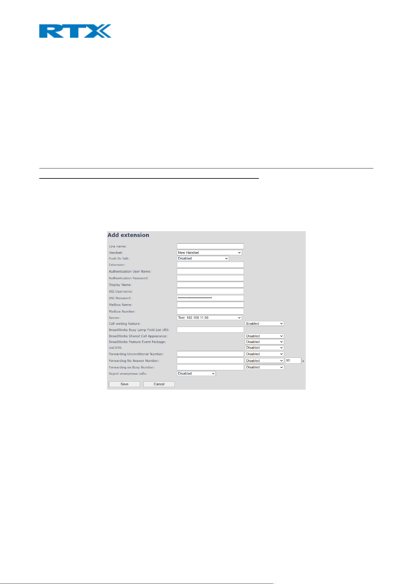
7.1.3.1 Add (edit) extension editor menu
The Add (Edit) Extension editor menu appears as soon as you select the Add extension link or select an
already existing extension. The view output for each base is shown in the screenshots below (Fig.23, 24) and
the displayed parameters are explained in the following table.
Figure 22 Add extension editor menu overview on B760

Figure 23 Add extension editor menu overview on B700/730
PARAMETER DEFAULT VALUE(S) DESCRIPTION
LINE NAME Empty Used in the following 2 cases:
Inform the user from which line an incoming call is received
User selects from which line to make an outgoing call
NOTE: This option is not present in B700/730
HANDSET New Handset The extension must be associated to a handset. By default, a new
handset can be configured. Alternatively, the user can select an
already existing handset, by choosing one from the drop-down menu
(Handset Idx x).
NOTE: For B700/730 this option is located on the right-hand side of the
page
PUSH-TO-TALK
(PTT)
Disabled The feature allows having P2P walkie-talkie, meaning voice calls
between handsets and headsets on the VoIP system. Enable the
feature to broadcast a PTT conference call to all portable devices.
NOTE: For B700/730 this parameter is located under the Handset menu
EXTENSION Empty Handset phone number or SIP username depending on the setup.
Possible value(s): 8-bit string length
Example: 1024, etc.
NOTE: The extension must also be configured in the SIP server in order
for this feature to function.
AUTHENTICATION
USERNAME
Empty Username: SIP authentication username of the extension (pre-
configured on the SIP server)
Permitted value(s): 8-bit string length
AUTHENTICATION
PASSWORD
Empty Password: SIP authentication password of the extension (pre-
configured on the SIP server)
Permitted value(s): 8-bit string length
DISPLAY NAME Empty Human readable name used for the given extension
Permitted value(s): 8-bit string length
NOTE: The name will not be displayed on handsets, using the modern
MMI interface
XSI USERNAME Empty To gain access to the XSI server, type in the SIP authentication
username

Permitted value(s): 8-bit string length
XSI PASSWORD Empty To gain access to the XSI server, type in the SIP authentication
password
Permitted value(s): 8-bit string length
MAILBOX NAME Empty Name of centralized system used to store phone voice messages that
can be retrieved by the recipient later.
Valid Input(s): 8-bit string Latin characters for the name
MAILBOX
NUMBER
Empty The number of the mailbox where voice messages are stored. This
number is to be dialed by the user to hear the voice messages. This is
done by long pressing key 1 on the handset.
Valid Input(s): 0 – 9, *, #
NOTE: The Mailbox Number parameter is available only when it is
enabled on the SIP server.
SERVER IP of Server 1 Select the FQDN or IP address of the SIP server (the SIP server should
be pre-configured on the Servers page)
Drop down menu to select between the various defined servers.
CALL WAITING
FEATURE
Enabled Used to enable/disable Call Waiting feature. If disabled, a second
incoming call will be rejected. If enabled, the second incoming call will
be presented as call waiting to be answered. The feature is only valid
when there is an active call.
NOTE: An extension can only receive 1 alerting call. This means that
during an alerting call that is not yet answered, the Call Waiting
feature is not valid. Therefore, all other calls will be rejected and not
queued.
BROADWORKS
BUSY LAMP FIELD
LIST URI
Empty The “BLF” feature on the handsets allows a specific extension to be
monitored for state changes. BLF monitors the status (busy or idle) of
extensions on the handset
Permitted value(s): URL String
NOTE: This feature does not work with Group call. Therefore, Group
call should be disabled.
NOTE: This option is not supported by B700/730
BROADWORKS
SHARED CALL
APPEARANCE
Disabled Enable Shared Call Appearance (SCA) to allow a group of SIP phones to
receive inbound calls directed to a single destination (shared line); in
this way, any phone from this group can answer the call, barge-in to
the active call, or retrieve the call placed on hold.
NOTE: Must be supported by SIP server
NOTE: This option is not supported by B700/730
BROADSOFT
FEATURE EVENT
PACKAGE
Disabled If enabled, the given SIP extension subscribes for the Broadsoft
Application Server Feature Event Package, and it becomes ready for
reception of SIP NOTIFY with status on the following Broadsoft Server
Services:
Do Not Disturb
Call Forwarding (Always, Busy, No answer)
The received status will be displayed in the handset idle display.
UACSTA Disabled Enable/Disable uaCSTA support
Empty
Number to which incoming calls must be re-routed, regardless of the
handset’s state.

FORWARDING
UNCONDITIONAL
NUMBER
Disabled
The feature must be enabled to function.
NOTE: Feature must also be enabled in the SIP server before it can
function in the network
FORWARDING
NO ANSWER
NUMBER
Empty
Number to which incoming calls must be re-routed when there is no
response from the SIP end node.
The feature must be enabled to function.
Specify the delay from a call to forward in seconds.
NOTE: Feature must also be enabled in the SIP server before it can
function in the network
Disabled
90
FORWARDING
ON BUSY
NUMBER
Empty Number to which incoming calls must be re-routed when SIP node is
busy.
The feature must be enabled to function
NOTE: Feature must also be enabled in the SIP server before it can
function in the network
Disabled
REJECT
ANONYMOUS
CALLS
Disabled If enabled, calls from anonymous numbers will automatically be
rejected.
NOTE: Call forwarding can also be configured from the handset by the user. For more details, please see
7.3.4.15 Call Forward
7.1.4 Handsets
For both bases (B700/730 and B760) the editor window of the handsets can be accessed by clicking on the
IPEI link of the desired device from the Extensions page. In addition to this, as mentioned in 7.1.3 Extensions,
the B700/730 has also a separate menu (Handset) for displaying the devices. Entering this menu allows you
to access the handset editor window by selecting the IPEI link of the desired handset or the Add Handset link.
A screenshot of the editor window can be seen below (Fig.25).
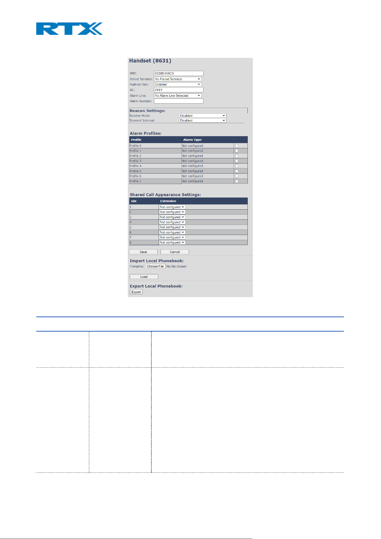
Figure 24 Handset editor window
PARAMETER DEFAULT VALUE(S) DESCRIPTION
IPEI Handset IPEI Displays the handset’s IPEI.
NOTE: For an already registered handset, changing the IPEI will
deregister the handset at the next location update.
PAIRED
TERMINAL
No Paired Terminal You can pair the handset with an RTX8930 headset.
For more details, please read the RTX8930 user guide.
NOTE: For B700/730 this option is available only if the Local Call groups
feature is disabled
NOTE: When pairing a RTX725x headset the user must consider the
following: When the headset is paired with the terminal idx of a
handset, it assumes the extension data of the handset. If pairing from
the Handset page and terminal idx of the headset is chosen, the
handset assumes the extension details of the headset. For details refer
to the RTX 725x Headsets System Guide.

PUSH-TO-TALK
(PTT)
Disabled
The feature allows having P2P walkie-talkie, voice calls between
handsets and headsets on the VoIP system. Enable the feature to
broadcast a PTT conference call to all portable devices.
AC FFFF
Displays the handset’s Access code. The AC is used at handset
registration.
NOTE: Changing the AC code for an already registered handset will
have no effect.
ALARM LINE
No Alarm Line
Selected
The line of multiline to be used for alarm call feature
ALARM NUMBER Empty Number to be dialed in case of a triggered alarm.
NOTE: Alarms must be assigned to the handset in order for this feature
to function
7.1.4.1 Beacon settings
This section allows the administrator to enable the handsets to receive or transmit beacons. These settings
are displayed only if the devices support the feature.
NOTE: RTX8630, RTX8431and RTX8436 do not support this feature
PARAMETER DEFAULT
VALUES
DESCRIPTION
RECEIVE MODE Disabled If enabled, the handset will list beacons in vicinity of the device and report it
to an external server.
NOTE: When this feature is configured and an alarm is triggered, the
strongest beacon will be included in the data sent to the message server.
Available options:
Enter/ Leave/ Enter or Leave proximity: Report to the external server when
the handset enters/ leaves/ enters or leaves vicinity of a beacon
RECEIVE
SENSITIVITY
Low Defines how close the handset should be to the beacon before detecting
enter / leave
Available options:
Low/ Medium/ High - The handset should be in close/ medium/ long range
to the beacon to detect enter / leave
RECEIVE SELECT N/A Select which beacon advertising packets should be listed by the handset
Available options:
iBeacon/ Altbeacon/ Eddystone: Listing for beacons transmitting an
iBeacon/ Altbeacon/ Eddystone advertising packet
TRANSMIT
INTERVAL
Disabled
If enabled the handset will transmit beacons.
Define the interval between the beacon transmits
Available options:

Short/ Step x/ Long
TRANSMIT POWER Low Define the range of the transmit
Available options:
Low/ Step x/ High
TRANSMIT SELECT N/A Select which beacon advertising packets should be transmitted by the
handset.
Available options:
iBeacon/ Altbeacon/ Eddystone
7.1.4.2 Alarm profiles
Alarm profiles are listed as soon as they are configured in the Alarm menu (refer to 7.1.17 Alarm). Check the
box of the desired profile for the specific handset. After configuration, the handset must be rebooted.
NOTE: The alarm feature is only available for some type of handsets (RTX8631, RTX8632, RTX8633 and
RTX8830).
NOTE: RTX8630 cannot send alarms, but it can receive them
7.1.4.3 Shared call appearance (SCA) settings
Each of the eight rows in the table represents an SCA status LED on the handset Idle screen. For each row it
is possible to specify which shared line an LED should display the state of.
• Only shared lines can be selected. This means that only extensions, defined for the handset for
which BroadWorks Shared Call Appearance is enabled, are included in the selector.
• A shared line can be reused for several LEDs. Each LED with the same shared line then corresponds
to different appearance-indexes for that line (1 LED = appearance-index 1, 2 LEDs = appearance-
indexes 1 and 2, and so on).
It is not necessary to select a shared line for all the LEDs. If an LED is not assigned to a line, its position on the
screen is simply empty.
NOTE: For B700/730 this option is available only if the Local Call groups feature is disabled
7.1.4.4 Import Local phonebook
This feature enables the administrator to import a phonebook with .csv/.txt/.lo file format to the specific
handset. This feature is using a browse file approach. After file selection, the load button must be pressed to
load the file. The system supports only the original .csv format. Please note, that some excel .csv formats are
not the original .csv format.
For details on the contact list structure, please refer to 9.1 Contact list structure.
NOTE: Depending on the handset type, a different number of entries can be saved:
RTX843x – 50 entries
RTX863x, RTX8830 – 250 entries
RTX8630 – 100 entries
7.1.4.5 Export Local phonebook
The Export local phonebook feature makes it possible to retrieve all contracts from a specific handset to a
.csv file format. The export button must be selected and then the file can be saved in a .csv format on the PC
or server.
NOTE: “Other” is not exported as this is considered private data.
NOTE: Supported characters are ASCII and Unicode.
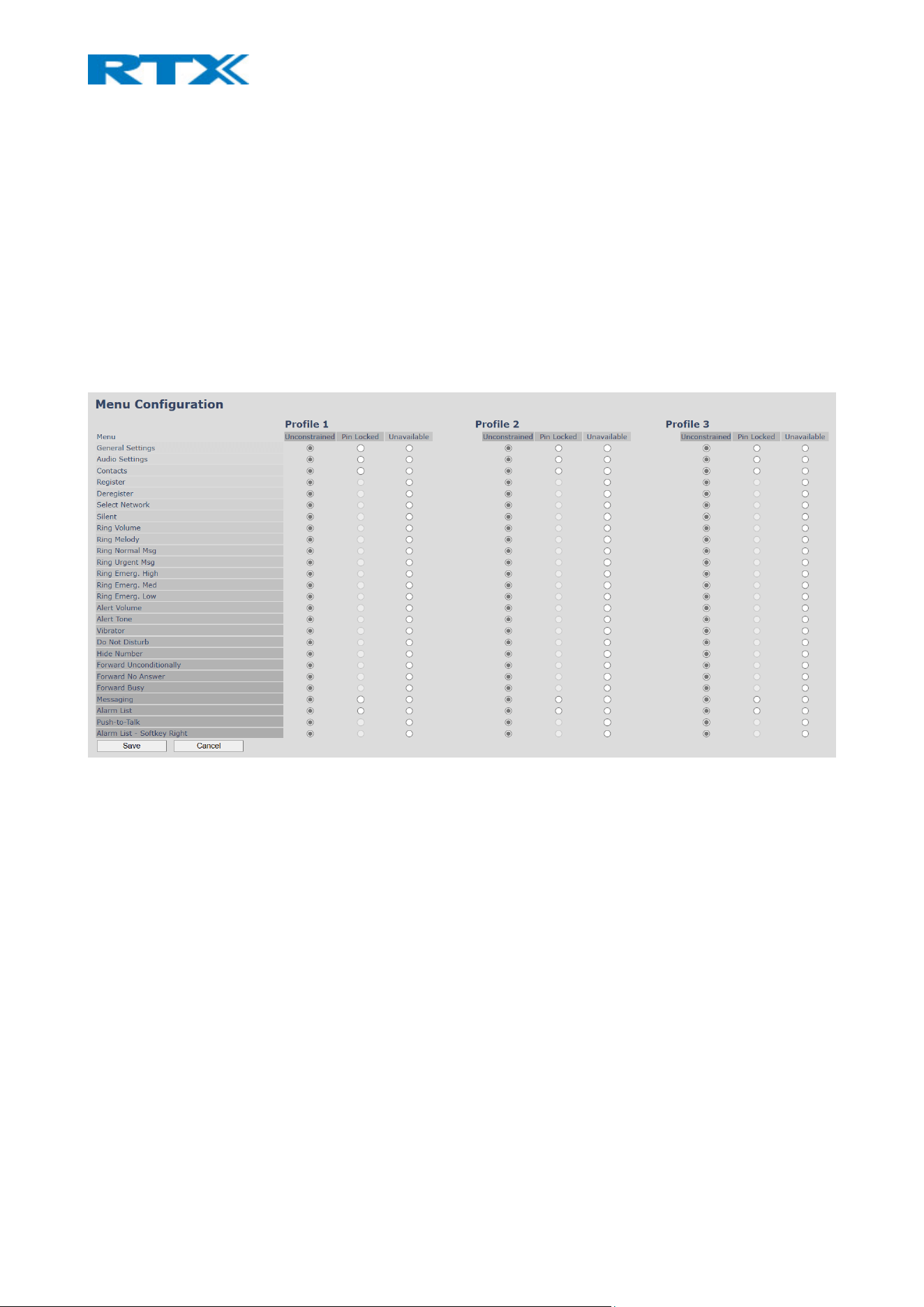
7.1.4.6 Menu Configuration
This submenu of Extensions allows the admin to restrain the user from manipulating device settings for the
handsets.
Figure 25 Extensions: Menu Configuration
7.1.5 Servers
This section presents and describes the different parameters available in the Servers configuration page
(Fig.26). Please note, that a maximum of 10 servers can be configured. Furthermore, within servers or even
with multi servers, extensions must always be unique. This means that, the same extension number on
server 1 cannot be re-used on server 2.
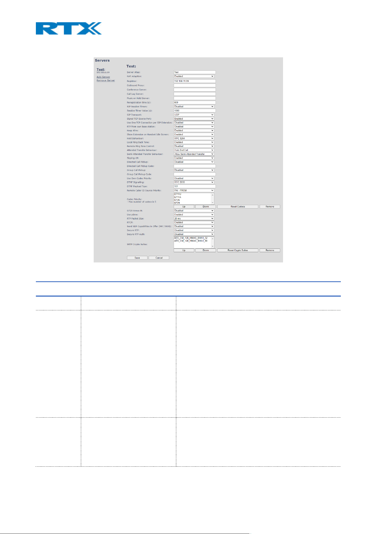
Figure 26 Servers page
PARAMETER DEFAULT VALUE DESCRIPTION
SERVER ALIAS Empty Displays the server name
NAT
ADAPTION
Disabled
To ensure all SIP messages go directly to the NAT gateway in
the SIP aware router.
If enabled and the system receives a SIP response to a
REGISTER request with a “Via” header that includes the
“received” parameter (ex: “Via: SIP/2.0/UDP
10.1.1.1:4540;received=68.44.20.1”), the base will adapt its
contact information to the IP address from the “received”
parameter. Thus, the base will issue another REGISTER
request with the updated contact information.
If NAT Adaption is disabled, the “received” parameter is
ignored.
REGISTRAR Empty SIP Server proxy DNS or IP address
Permitted value(s): AAA.BBB.CCC.DDD:<Port-Number> or
<URL>:<Port-Number>
Example: “192.168.0.1”, “192.168.0.1:5062”,

“nat.company.com” and “sip:[email protected]:5065”.
NOTE: Specifying the port number is optional.
OUTBOUND
PROXY
Empty
This is a Session Border Controller DNS or IP address (Or SIP
server outbound proxy address)
Set the Outbound proxy to the address and port of the
private NAT gateway, so that the SIP messages will be sent
via the NAT gateway.
Permitted value(s): AAA.BBB.CCC.DDD or <URL> or
<URL>:<Port-Number>
Examples: “192.168.0.1”, “192.168.0.1:5062”,
“nat.company.com” and “sip:[email protected]:5065”.
If the value in the field is empty, then a call is made via
Register.
CONFERENCE
SERVER
Empty Broadsoft conference feature.
Set the IP address of the conference server.
In case an IP is specified, pressing the conference option on
the handset will establish a connection to the conference
server.
If the field is empty, the original 3-party local conference is
used.
CALL LOG
SERVER
Empty Broadsoft call log feature.
Set the IP address of the XSI call log server.
If the field is empty, the local call log is used
NOTE: An internal call log cannot be accessed by the handset,
if an external one is present
MUSIC ON
HOLD SERVER
Empty
Add the address of a server to ensure that music is on when
call is on hold
RE-
REGISTRATION
TIME
600
The “expires” value in SIP REGISTER requests. This value
indicates how long the current SIP registration is valid, and
hence it specifies the maximum time between SIP
registrations for the given SIP account.
Permitted value(s): A value below 60 sec is not
recommended, Max value 65636
SIP SESSION
TIMERS:
Disabled
RFC 4028. A “keep-alive” mechanism for calls. The session
timer value specifies the maximum time between “keep-
alive” or more correctly session refresh signals. If no session
refresh is received, as soon as the timer expires, the call will
be terminated.

Default value is 1800s according to the RFC.
Min: 90s.
Max: 65636s.
If disabled, session timers will not be used.
SESSION
TIMER VALUES
(S):
1800 Default value is 1800s according to the RFC.
If disabled, session timers will not be used.
Min: 90s, Max: 65636s
SIP
TRANSPORT
UDP
Select the protocol that is to be used during SIP calls (UDP,
TCP or TLS 1.2)
SIGNAL TCP
SOURCE PORT
Disabled
When SIP Transport is set to TCP or TLS, a TCP (or TLS)
connection will be established for each SIP extension. The
source port of the connection will be chosen by the TCP
stack, and hence the local SIP port parameter, specified
within the SIP/RTP Settings ( Error! Reference source not f
ound. SIP/RTP Settings), will not be used. The “Signal TCP
Source Port” parameter specifies if the used source port
must be signaled explicitly in the SIP messages.
USE ONE TCP
CONNECTION
PER SIP
EXTENSION:
Disabled
When using TCP as SIP transport, choose if a TCP/TLS
connection should be established for each SIP extension, or if
the base station should establish one connection which all
SIP extensions use.
Please note, that if TLS is used and SIP server requires client
authentication (and requests a client certificate), this setting
must be set to disabled.
0: Disabled. (Use one TCP/TLS connection for all SIP
extensions)
1: Enabled. (Use one TCP/TLS connection per SIP extension).
RTP FROM
OWN BASE
STATION:
Disabled
If disabled, RTP stream will be send from the base where the
handset is located. If enabled, the RTP stream will always be
sent from the base, where the SIP registration is made.
KEEP ALIVE Enabled
This directive defines the window period (30 sec.) to keep
opening the port of relevant NAT-aware router(s), etc.
SHOW
EXTENSION
ON HANDSET
IDLE SCREEN
Enabled
If enabled, the extension will be visible on handset idle
screen.
NOTE: The name will not be displayed on handsets, using the
modern MMI interface
HOLD
BEHAVIOUR
RFC 3264 Specify the hold behavior by the handset’s “Hold” feature.
RFC 3264: Hold is signaled according to RFC 3264, i.e. the
connection information part of the SDP contains the IP

address of the endpoint. Depending on the context, the
direction attribute is sent only.
RFC 2543: The ”old” way of signaling HOLD. The connection
information part of the SDP is set to 0.0.0.0. Depending on
the context, the direction attribute is sent only.
LOCAL RING
BACK TONE
Enabled
In case the server does not play local ring back tone, the
handset will do it.
REMOTE RING
TONE
CONTROL
Disabled
It enables the server to control the ring tone that is used on
the handsets.
When enabled, the ringtone selection will be available in
Management page.
ATTENDED
TRANSFER
BEHAVIOUR
Hold 2
nd
Call
When there are two calls, and one call is on hold, it is
possible to perform attended transfer. When the transfer
soft key is pressed in this situation, the active call is placed
on hold before the SIP REFER request is sent. However, it is
experienced that some PBX’s do not expect that the 2nd call
is put on hold, and therefore attended transfer fails on these
PBX’s.
The "Attended Transfer Behavior" feature defines whether
the 2nd call should be put on hold before the REFER is sent.
If Hold 2nd Call is selected, the 2nd call will be held before
REFER is sent.
If Do Not Hold 2nd Call is selected, the 2nd call will not be
held before the REFER is sent
SEMI-
ATTENDED
TRANSFER
BEHAVIOUR
Allow Semi-Attended Transfer
This feature can be enabled/disabled by selecting one of the
following options:
Allow Semi-Attended Transfer
Prohibit Semi-Attended Transfer
SIPPING-19 Enabled
The setting controls Sipping-19 in a conference
NOTE: The conference package must be enabled by RTX in
order to use the Sipping-19 feature
DIRECT CALL
PICKUP
Disabled
This is part of the BroadWorks SCA feature. If enabled, a
direct call pickup code is sent to the handsets
DIRECT CALL
PICKUP CODE
Empty Code used to direct call pick up
GROUP CALL
PICKUP
Disabled
Enable call group pickup
GROUP CALL
PICKUP CODE
Empty
Code used to pick up a group call

USE OWN
CODEC
PRIORITY
Disabled Disabled by default
By enabling the system codec, priority during incoming call is
used, instead of the calling party priority.
E.g. If base has G722 as top codec and the calling party has a
law on top and G722 is further down the list, the G722 will
be chosen as a codec for the call.
DTMF
SIGNALLING
RFC 2833
Conversion of decimal digits (‘*’ and ‘#’) into sounds that
share similar characteristics with voice to easily traverse
networks designed for voice
SIP INFO: Carries application-level data along SIP signaling
path (e.g.: Carries DTMF digits generated during SIP session,
or sending of DTMF tones via data packets in the same
internet layer as the Voice Stream, etc.).
RFC 2833: DTMF handling for gateways, end systems and
RTP trunks (e.g.: Sending DTMF tones via data packets in
different internet layers as the voice stream)
Both: Enables SIP INFO and RFC 2833 modes.
DTMF
PAYLOAD
TYPE
101
This feature enables the user to specify a value for the DTMF
payload type / telephone event (RFC2833).
REMOTE
CALLER ID
SOURCE
PRIORITY
FROM SIP information field used for Caller ID source
PAI - FROM
FROM
ALERT_INFO - PAI - FROM
CODEC
PRIORITY
G.711U
G.711A
G.726
G.722
G.729
OPUS
BV32
Defines the codec priority that base stations, used for audio
compression and transmission.
Possible Option(s): G.711U, G.711A, G.726, G.722, G.729,
OPUS, BV32
NOTE: Modifications of the codec list must be followed by a
“Reset Codecs” and “Reboot chain” from the multi cell page,
to change and update handsets.
NOTE: With G.722 as priority, the number of simultaneous
calls per base station will be reduced from 10 to 5 calls. With
G.722 in the list, the codec negotiation algorithm is active,
causing the handset (phone) setup time to be slightly slower
than if G.722 is removed from the list. Furthermore, it will
reserve audio resources to be able to handle the possible
G722 call and thus, the maximum number of possible
narrowband calls will be reduced by one extra.

NOTE: To use G.729 and OPUS, add on DSP module must be
installed in all base stations. Contact your local dealer for
price information.
NOTE: If BV32 is the only codec used (the only one in the
priority list), the user should use handsets that support BV32
(RTX8631-3), else a call will not be established.
G729 Annex B
Enable/Disable Annex B of codec G729
NOTE: Both parts must support it in order to avoid noise and
any other kind of voice interruption
USE PTIME Enabled
Use the RTP Packet size, chosen in the below setting.
RTP PACKET
SIZE
20ms
The packet size offered as preferred RTP packet size by 8630
when RTP packet size negotiation.
Options available: 20ms, 40ms, 60ms, 80ms
RTCP Enabled Enable/Disable RTCP
SEND SDP
CAPABILITIES
IN OFFER
(RFC5939)
Disabled Enable to support RFC 5939
SECURE RTP Disabled
When enabled, RTP will be encrypted (AES-128) using the
key negotiated via the SDP protocol at call setup.
SECURE RTP
AUTH
Disabled
When enabled, secure RTP is using authentication of the RTP
packages.
NOTE: With enabled SRTP authentication, maximum 10
concurrent calls are possible per base(B760) in a single or
multi cell system.
SRTP CRYPTO
SUITES
AES_CM_128_HMAX_SHA1_32
AES_CM_128_HMAX_SHA1_80
Field list of supported SRTP Crypto Suites. The device is born
with two suites.
7.1.6 Network
This subchapter aims to present and describe the different parameters available in the Network configuration
menu. Similar to the data representation on the Network page (Fig.27), the available settings are divided into
sections and further explained in the following tables. All changes on this page require reboot to take effect.
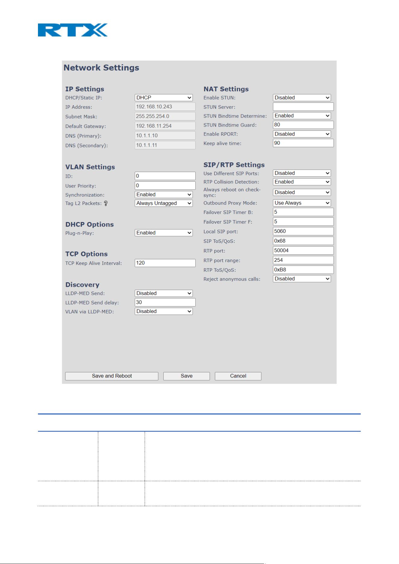
Figure 27 Network page
7.1.6.1 IP Settings
PARAMETER DEFAULT
VALUES
DESCRIPTION
DHCP/STATIC IP DHCP Select the technology that will be used to allocate an IP address to the base
DHCP: IP addresses are allocated automatically from a pool of leased
addresses. If the user selects the DHCP option, the other IP settings will not
be editable.
Static IP: The network administrator manually assigns IP addresses
IP ADDRESS NA 32-bit IP address of the device (e.g. base station). 64-bit IP address will be
supported in the future.

Permitted value(s): AAA.BBB.CCC.DDD
SUBNET MASK NA The device’s subnet mask. This is a 32-bit combination that describes which
portion of the address identifies the network and which portion of the
address identifies the node.
Permitted value(s): AAA.BBB.CCC.DDD
DEFAULT
GATEWAY
NA Device’s default network router/gateway (32-bit). The IP address of the
network router that acts as an entrance to another network. This device
provides a default route for TCP/IP hosts to use when communicating with
other hosts on hosts networks.
Permitted value(s): AAA.BBB.CCC.DDD
DNS (PRIMARY) NA Main server to which a device directs Domain Name System (DNS) queries.
This is the IP address of a server that contains mappings of DNS domain
names to various data, e.g. IP address, etc. You must specify this option
when static IP address option is chosen.
Permitted value(s): AAA.BBB.CCC.DDD or <URL>
DNS (SECONDARY) NA This is an alternate DNS server.
MDNS Disabled Enable to allow Multicast Domain Name system (MDNS)
7.1.6.2 VLAN settings
Enable users to define devices (e.g. base station, etc.) with different physical connection to communicate as
if they are connected on a single network segment.
The VLAN settings can be used on a managed network with separate Virtual LANs (VLANs) for sending voice
and data traffic. To work on these networks, the base stations can tag voice traffic, generated on a specific
“voice VLAN”, using the IEEE 802.1q specification.
PARAMETER DEFAULT VALUES DESCRIPTION
ID 0 A 12-bit identification of the 802.1Q VLAN.
Permitted value(s): 0 to 4094 (only decimal values are accepted)
A VLAN ID of 0 is used to identify priority frames and ID of 4095 is
reserved.
Null means no VLAN tagging or No VLAN discovery through DHCP.
USER PRIORITY 0 This is a 3-bit value that defines the user priority.
Permitted value(s): 8 priority levels (i.e. 0 to 7)
Values are from 0 (best effort) to 7 (highest); 1 represents the lowest
priority. These values can be used to prioritize different classes of traffic
(voice, video, data, etc.).
SYNCHRONIZATION Disabled When enabled, the VLAN ID is automatically synchronized between the
bases in the chain. Bases will be automatically rebooted during the
synchronization.
NOTE: If using different VLANs, the synchronization must be disabled. The
setting must be changed on each base station as there is no
synchronization between them.
NOTE: This feature is not supported by B700/730
TAG L2 PACKETS Always Untagged
This feature allows the user to configure the tagging of LLDP/CDP/EAP
packets. It can either be set to Always Untagged or to Follow VLAN ID.

7.1.6.3 DHCP Options
PARAMETER DEFAULT VALUES DESCRIPTION
PLUG-N-PLAY Enabled DHCP option 66 is enabled by default to automatically provide PBX IP
address to the base.
7.1.6.4 TCP Options
PARAMETER DEFAULT VALUES DESCRIPTION
TCP KEEP ALIVE
INTERVAL
120s Specifies the interval that the client waits for before sending a keep-alive
message on a TCP connection.
7.1.6.5 Discovery
PARAMETER DEFAULT VALUES DESCRIPTION
LLDP-MED
SEND
Disabled If enabled, the base station will send 5 LLDP-MED messages when started
LLDP-MED
SEND DELAY
30 Sends messages every 30 seconds to inform the network about its LLDP-
MED data
NOTE: This option works only if the first parameter is enabled (LLDP-MED
SEND)
VLAN VIA LLDP-
MED
Disabled If enabled, the base station will try to retrieve a VLAN ID from the received
LLDP-MED from a switch
NOTE: This feature is available only if the first parameter is enabled (LLDP-
MED SEND)
CDP SEND DISABLED Enable to send CDP messages
NOTE: This feature is not supported by B700/730
CDP SEND
DELAY
60 Define the delay between messages in seconds
NOTE: This feature is not supported by B700/730
7.1.6.6 NAT settings
The following table defines some options available when NAT aware routers are enabled in the network.
PARAMETER DEFAULT VALUES DESCRIPTION
ENABLE STUN Disabled Enable to use STUN
STUN SERVER Empty Permitted value(s): AAA.BBB.CCC.DDD (Currently only Ipv4 is supported)
or URL (e.g.: firmware.rtx.net).
STUN BINDTIME
DETERMINE
Enabled Enable/Disable the use of STUN Bindtime
STUN BINDTIME
GUARD
80 Permitted values: Positive integer; default is 90; unit is in seconds
ENABLE RPORT Disabled Enable to use RPORT in SIP messages.
KEEP ALIVE TIME 90 Defines the frequency of how keep-alive are sent to maintain NAT
bindings.
Permitted values: Positive integer; default is 90; unit is in seconds

7.1.6.7 SIP/RTP settings
PARAMETER DEFAULT VALUES DESCRIPTION
USE DIFFERENT
SIP PORTS
Disabled If disabled, the Local SIP port parameter specifies the source port used for
SIP signaling in the system.
If enabled, the Local SIP Port parameter specifies the source port used for
first user agent (UA) instance. Succeeding UA’s will get succeeding ports.
RTP COLLISION
DETECTION
Enabled Enabled: If there are two sources with the same SSRC, then the following
RTX is discarded.
Disabled: No check – device will accept all sources.
ALWAYS
REBOOT ON
CHECK-SYNC
Disabled Reboot base station when new configuration is loaded.
OUTBOUND
PROXY MODE
Use Always Use Always: All outbound calls are sent to the outbound proxy
Only Initial request: Only use outbound proxy for initial SIP requests
FAILOVER SIP
TIMER B
5 When the time expires and the corresponding SIP transaction fails, failover
will be triggered
FAILOVER SIP
TIMER F
5 When the time expires and the corresponding SIP transaction fails, failover
will be triggered
LOCAL SIP PORT 5060 The source port used for SIP signaling
Permitted values: Positive integer
SIP TOS/QOS 0x68 Priority of call control signaling traffic, based on both IP Layers of Type of
Service (ToS) byte. ToS is referred to as Quality of Service (QoS) in packet-
based networks.
Permitted values: Positive integer, default is 0x68
RTP PORT 50004 The first RTP port to be used for RTP audio streaming.
Permitted values: Positive integer
RTP PORT
RANGE
40 The number of ports that can be used for RTP audio streaming.
Permitted values: Positive integers, default is 40
RTP TOS/QOS 0xB8 Priority of RTP traffic based on the IP layer ToS (Type of Service) byte. ToS
is referred to as Quality of Service (QoS) in packet-based networks.
See RFC 1349 for details. “Cost bit” is not supported.
o Bit 7..5 defines precedence.
o Bit 4..2 defines Type of Service.
o Bit 1..0 are ignored.
Setting all three of bit 4..2 will be ignored.
Permitted values: Positive integer, default is 0xB8
REJECT
ANONYMOUS
CALLS
Disabled If disabled, all calls will be received.
If enabled, anonymous calls will be automatically rejected at the PBX. This
means that these calls will be rejected regardless of what is set on the
individual extension page
NOTE: If you wish to enable this feature only for certain extensions, then
the setting must be set individually (refer to 7.1.3.1 Add (edit) extension
editor menu for more information)
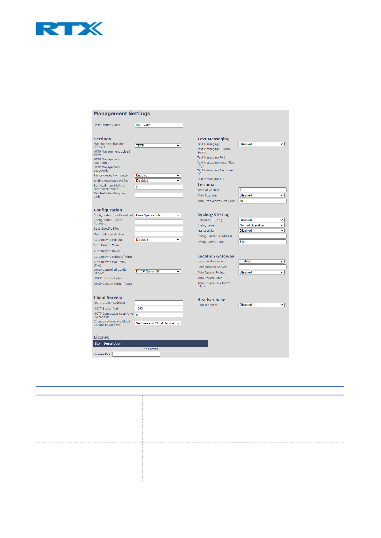
7.1.7 Management
The Management menu allows the administrator to configure the base stations to perform specific functions,
such as enabling text messaging, configuration file download, etc. The available settings are divided into
sections, similar to the overview of the Management page (Fig.28), and further described in the following
tables.
Figure 28 Management page
7.1.7.1 Settings
PARAMETER Default value Description
BASE STATION
NAME
SME VoIP It indicates the title that appears at the top window of the browser and is
used in the Multi cell page
Maximum characters: 35
MANAGEMENT
TRANSFER
PROTOCOL
TFTP The protocol assigned for configuration file and central directory
Valid Input(s): TFTP, HTTP, HTTPs
HTTP
MANAGEMENT
UPLOAD SCRIPT
Empty The folder location or directory path that contains the configuration files
of the Configuration server. The configuration upload script is a file
located in, for example a TFTP server or Apache Server, which is also the
configuration server.
Permitted value(s): /<configuration-file-directory>

Example: /CfgUpload
NOTE: Must begin with (/) slash character. Either / or \ can be used.
HTTP
MANAGEMENT
USERNAME
Empty Username should be entered to provide access to the configuration
server.
Permitted value(s): 8-bit string length
HTTP
MANAGEMENT
PASSWORD
Empty Password should be entered to provide access to the configuration server.
Permitted value(s): 8-bit string length
FACTORY RESET
FROM BUTTON
Enabled If enabled, a factory reset will be possible by pressing the button on the
base station
If disabled, no action will be present by pressing the button on the base
station.
NOTE: The reset procedure clears all personal and security assets: SIP
credentials, messages, logs, contact lists, and ex-factory certificate
storage. Residual data is not retained across reboots.
ENABLE
AUTOMATIC
PREFIX
Disabled Disabled: Feature is turned off
Enabled: The base will add the leading digit defined in “Set Prefix for
Outgoing Calls”.
Enabled + fall through on * and #: The base will enable detection of * or #
at the first digit of a dialed number, meaning that users can type any of
these symbols before dialing a number. In addition to this, the leading
digit defined in “Set Prefix for Outgoing Calls” is still valid, which means
that it will be added by the PBX to the dialed number.
Examples:
1: dialed number on handset *1234 - > dialed number to the PBX *1234
2: dialed number on handset #1234 - > dialed number to the PBX #1234
3: dialed number on handset 1234 - > dialed number to the PBX 01234
SET MAXIMUM
DIGITS FOR
INTERNAL
NUMBERS
0 Used to detect internal numbers. In case of internal numbers, no prefix
number will be added to the dialed number.
SET PREFIX FOR
OUTGOING CALLS
Empty Set the prefix for outgoing calls. Users need to dial this prefix to get an
outside line.
7.1.7.2 Configuration
There are three ways of configuring the system:
• Manual configuration via the Web server (Web UI)
• Manual upload of a configuration file from a local drive, via the “Configuration” page on the Web
server (Web UI) (see 7.1.21 Configuration)
• Automatic download of configuration files from a configuration server (see the table below)
PARAMETER Default value Description
CONFIGURATION
FILE DOWNLOAD
Disabled Base Specific file: Used when configuring a single cell base
Base and Multi cell Specific File: Used on out of factory bases to specify
VLAN and settings / used when configuring a multi cell system
Multi cell Specific file: Used when a multi cell system is present
NOTE: For B700/730, the last two settings are displayed as “Dual Cell
Specific file”

CONFIGURATION
SERVER ADDRESS
Empty Server/device that stores the configuration file of the base station.
Type: DNS or IP address
Permitted value(s): AAA.BBB.CCC.DDD or <URL>
BASE SPECIFIC
FILE
Empty The file should be named after the MAC address of the base. An example
is the file 00087b1573ba.cfg
In a multi/dual cell system, the base specific file contains the network
settings (for example: vlan, static IP, MAC Address, etc.)
MULTI CELL
SPECIFIC FILE
Empty The file contains all data, except the specific network related settings
(vlan, static IP, MAC address,etc). The file should be named after the
chain ID number of the system
Permitted value(s): Format of file is chain ID.cfg
NOTE: For B700/730, this field is displayed as “Dual Cell Specific file”
AUTO RESYNC
POLLING
Disabled
Enable the base station to look for a new configuration file, within a
predefined time interval
AUTO RESYNC
TIME
00:00 A 24-hour setting
Specify the time when the base station should load the configuration file
AUTO RESYNC
DAYS
0 Number of days between Auto Resync
AUTO RESYNC
PERIODIC (MIN)
0 Number of minutes between Auto Resync
AUTO RESYNC
MAX DELAY
(MIN)
15 Delay time in min, to prevent all base stations from asking for the
configuration file at the same time
DHCP
CONTROLLED
CONFIG SERVER
Disabled Provisioning server options.
DHCP Option 66: Search for the provisioning file via the TFTP boot up
server.
DHCP Custom Option: Search for the provisioning file via the custom
option
DHCP Custom Option & Option 66: Search for the provisioning file, first
via custom option and then via Option 66
From v460, the base station supports configuration files of up to 1 MB
DHCP CUSTOM
OPTION
Empty By default, it is option 160, but custom option can be defined.
An option 160 URL defines the protocol and path information by using a
fully qualified domain name for clients that can use DNS.
NOTE: Option 160 can be used to indicate the URL to a file server and
optionally also a file name. This can be used in cases when HTTP, HTTPS or
FTP is required as file transfer protocol. If option 160 is set from Custom
Option, it takes priority over option 66.
DHCP CUSTOM
OPTION TYPE
Empty URL: URL of server with path
Example of URL: http://myconfigs.com:5060/configs
IP Address: IP of server with path.
Default configuration file on server must follow the name: MAC.cfg

7.1.7.3 Cloud Service
This section presents the available settings for configuring the RTX Cloud service.
NOTE: This feature is not supported by B700/730
PARAMETER Default value Description
MQQT BROKER ADDRESS Empty Broker IP address or domain name
NOTE: The connection between the Cloud Service and the base is
stopped if the broker URL is disabled.
MQQT BROKER PORT 1883 Broker port (the port on the Broker URL)
Maximum value: 65535
Port 1883 – MQQT connection is TCP
Port 8883 – MQQT connection is TLS
MQQT CONNECTION
KEEP ALIVE (SECONDS)
60 Defines how long the MQTT connection should be kept alive before
data transferred is required.
Maximum value: 255
CHANGE SETTINGS VIA
CLOUD SERVICE OR VIA
BASE
Via base and
Cloud Service
It is possible to decline settings request from the Cloud Service.
This field can also enable Cloud Control for 24 hours, meaning that it
is possible to change the settings on the base for 24 hours.
7.1.7.4 License
PARAMETER DEFAULT VALUE DESCRIPTION
LICENSE None This feature allows the administrators to register RTX8930 generic
headsets to the system. License key must be obtained from authorized
resellers and only license matching the system’s provider code will work.
NOTE: Changes to this feature require base station reboot.
7.1.7.5 Text messaging
PARAMETER DEFAULT VALUE DESCRIPTION
TEXT MESSAGING Disabled Enable messaging with the use of a Message/Alarm server
Enable Without Server: this allows a handset to send messages to other
handsets in the same system configuration
NOTE: Changes to this feature require base station reboot.
TEXT MESSAGING
& ALARM SERVER
Empty Permitted value(s): AAA.BBB.CCC.DDD or <URL>
NOTE: Text messaging server uses UDP and does not support TLS
TEXT MESSAGING
PORT
1300 Port number of the message server
TEXT MESSAGING
KEEP ALIVE (M)
30 Defines the frequency of how keep-alive messages are sent
Permitted values: Positive integer, unit is in minutes
TEXT MESSAGING
RESPONSE (S)
30 Defines the frequency of response timeout
Permitted values: Positive integer, unit is in seconds
TEXT MESSAGING
TTL
0 Defines the text messaging time to live
Permitted values: Positive integer, unit is in seconds
SELECT ALARM
SORTING
Priority Allows the user to choose parameter to sort alarm messages after.
Could be by Priority or Timestamp.

7.1.7.6 Terminal
PARAMETER DEFAULT VALUE DESCRIPTION
KEEP ALIVE (M) 0 If different from “0”, the handset sends an emergencyLocationMsg
containing the RSSI measurements with interval “x” that is set.
Permitted values: Positive integer, unit is in minutes
AUTO STOP
ALARM
Disabled Enable to activate “Auto Stop Alarm Delay”
AUTO STOP
ALARM DELAY (S)
30 Handset automatically stops alarm announcement (emergencySms) after
“x” sec.
7.1.7.7 Syslog/SIP log
PARAMETER DEFAULT VALUE DESCRIPTION
UPLOAD OF SIP
LOG
Disabled Enable this option to save low level SIP debug messages on the server. The
SIP logs are saved in the file format:
<MAC_Address><Time_Stamp>SIP.log
SYSLOG LEVEL Normal
Operation
Off: No data is saved on the syslog server
Normal Operation: Normal operation events are logged, as well as
incoming calls, outgoing calls, handset registration, DECT location, call lost
(due to busy state), critical system errors and general system information.
System Analyze: Contains the messages from Normal Operation, including
handset roaming and handset firmware update status
Debug: Information is used for debugging purposes by RTX. Should not be
enabled during normal operation. Only when an issue occurs and
debugging is required.
TLS SECURITY Disabled If enabled, it uses encrypted TCP, else - UDP
SYSLOG SERVER
IP ADDRESS
Empty Type in the IP address of the syslog server.
Permitted value(s): AAA.BBB.CCC.DDD or <URL>
SYSLOG SERVER
PORT
514 Port number of the syslog server.
7.1.7.8 Location Gateway
PARAMETER DEFAULT VALUE DESCRIPTION
LOCATION
GATEWAYS:
Disabled Enable to allow location gateways to register to the system.
NOTE: After enabling the feature, a new menu will be added (Location
gateways) on the left-handed navigation panel.
CONFIGURATION
SERVER:
Empty Server/device that stores the configuration file of the location gateway
Permitted value(s): AAA.BBB.CCC.DDD or <URL>
AUTO RESYNC
POLLING
Disabled The poll enables the configuration server to start the provisioning process
for the location gateway devices that it chooses. If enabled, it enables an
automatic configuration synchronization poll for the location gateway(s)
AUTO RESYNC
TIME
00:00 The time of the day that the automatic synchronization will occur
(HH:MM).
AUTO RESYNC
MAX DELAY
(MIN)
15 To distribute the load as such, that all location gateways do not sync at the
exact same time, the Auto Resync Max Delay can be set to delay the poll
trigger with a given number of minutes. The delay will be a random
number between 0 minutes and the value given in this parameter.
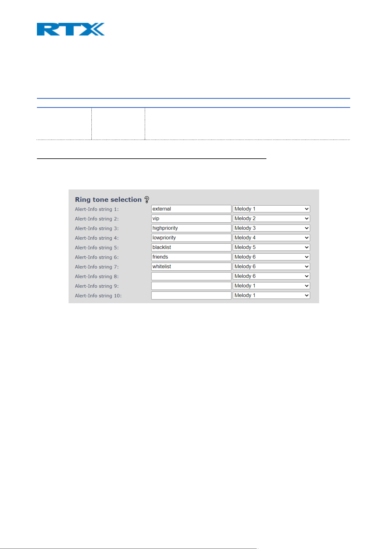
7.1.7.9 Headset base
The following table presents the available settings for enabling the Headset base station.
NOTE: This feature is not supported by B700/730
PARAMETER Default value Description
HEADSET BASE Disabled Enable the setting to allow headset base registrations
NOTE: After enabling the feature, a new menu will be added (Headset
base) on the left-handed navigation panel.
7.1.7.10 Ring Tone Selection
This menu is only present when Remote ring tone control is enabled in Servers.
Allows the user to modify the melodies and alert info for Remote ring tone control. The Alert info string can
have max length of 20 bytes. (NOTE: Special characters may use more than 1 byte.)
Figure 29 Ring tone selection
NOTE: Something to be aware of when setting up things on the server side is that there needs to be an exact
match between the received Alert-Info string from the SIP INVITE and the Alert-Info string otherwise default
value is used. Example: Myfriends vs. MyFriends.
7.1.8 Firmware update
The settings on this page allow the system administrator to set the desired firmware which the devices (base
stations and SIP nodes) should upgrade/downgrade to and upload a startup/background picture to the
handsets. The handset firmware/picture update status can be monitored on the Extensions page and the
repeater firmware update status - on the Repeaters page. Base firmware update status can be found on the
Multi/Dual cell or the Home/Status page. The screenshot below (Fig.29) illustrates the available options on
the Firmware page, followed by a table with parameter definitions. For more details on how to
upgrade/downgrade the firmware, or upload an image, please see 8.4 Firmware Upgrade procedure.
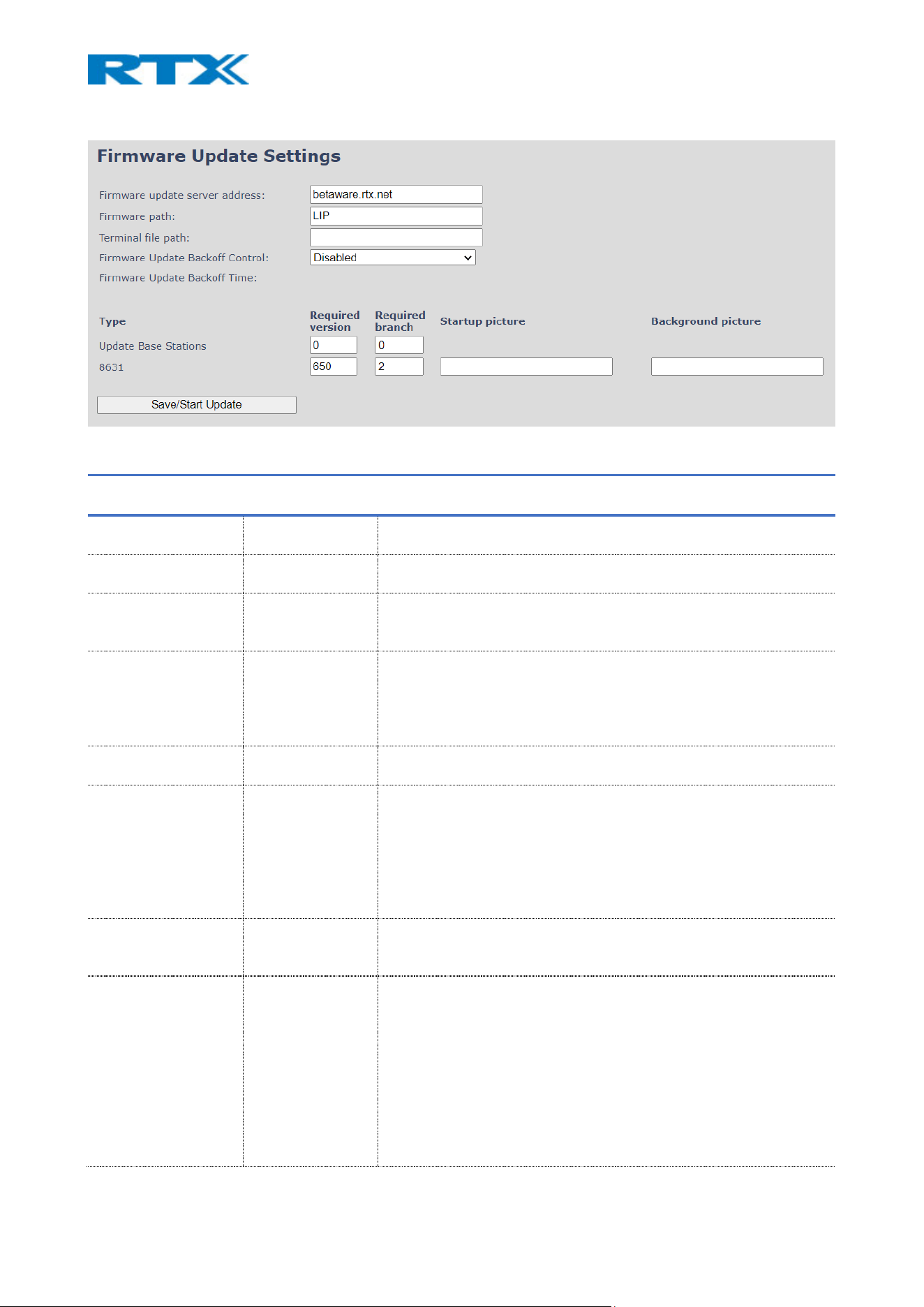
Figure 30 Firmware update page
PARAMETER DEFAULT
VALUE(S)
DESCRIPTION
FIRMWARE UPDATE
SERVER ADDRESS
Empty IP address or URL of the firmware server
Valid Inputs: AAA.BBB.CCC.DDD or <URL>
FIRMWARE PATH Empty Location of the firmware files on the server (the folder where they
are stored)
TERMINAL FILE PATH Empty Location of the image files (the folder where the background and
start up image are stored, along with the voice prompt file for the
headsets).
FIRMWARE UPDATE
BACKOFF CONTROL
Disabled In case of failed file download, this feature allows the user to set
backoff control. That means the base station will retry downloading
the firmware file again in the set time (depending on the mode
chosen).
There are 3 available modes: Static, Linear and Exponential.
FIRMWARE UPDATE
BACKOFF TIME
Empty When Backoff Update time enabled, we can enter the time interval
for retry the firmware download.
REQUIRED VERSION Empty Version of the firmware to be upgraded (or downgraded) to on
handset, repeater, base station, and headset.
Valid Input(s): 8-bit string length. E.g., 530
NOTE: Value version “0” will disable the firmware upgrade
NOTE: Two handset types will be serial firmware upgraded. For
example, first type 8630, then type 8430.
REQUIRED BRANCH
Empty Branch of the firmware to be upgraded (or downgraded) to on
handset, repeater, base station, and headset.
Valid Input(s): 8-bit string length. E.g., 1
STARTUP PICTURE Empty Name of the startup picture you wish to have on the handsets when
they are powered up.
NOTE: Images have the same resolution as the screen on the
handset(s); Resolution info can be found in the handset datasheets.
If the image does not have the same resolution as the screen, it will be
placed in the top left corner. If it is too small, the rest of the screen
will be black. If it is too large, only the left portion of the image will be
shown.
NOTE: Only .BMP is files are supported.
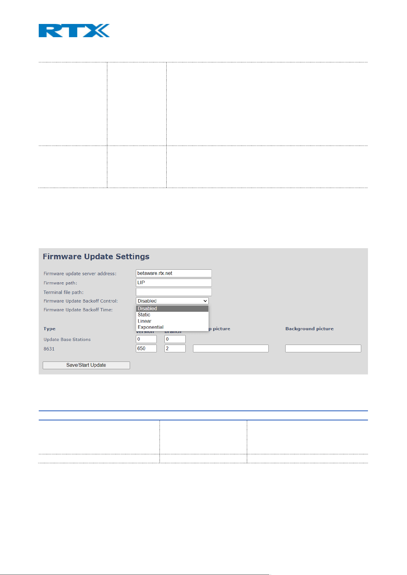
BACKGROUND
PICTURE
Empty Name of the background picture you wish to have on the handset’s
screen
NOTE: Images have same resolution as the screen on the handset(s),
Resolution info can be found in the handset datasheets.
If the image does not have the same resolution as the screen, it will be
placed in the top left corner. If it is too small, the rest of the screen
will be black. If it is too large, only the left portion of the image will be
shown
NOTE: Only .BMP is files are supported.
VOICE PROMPT Empty Name of the voice prompt file.
This feature is only available for the headsets.
NOTE: When updating the voice prompt make sure that the correct
Terminal path is given. It is also important to write the entire name of
the file in the provided space (together with ".fwu").
7.1.8.1 Firmware Update Backoff Control
This feature allows the user to set a backoff in case of failure to obtain the firmware update file from the
server. The default value of the feature is Disabled. When clicked the arrow, we are given to choose from
the dropdown menu between three modes that differ in the delay between each attempt.
Figure 31 Firmware update Backoff Control
SETTING DEFAULT VALUE MAXUMUM VALUE
FIRMWARE UPDATE BACKOFF CONTROL Empty 0. Disabled
1. Static
2. Linear
3. Exponential
FIRMWARE UPDATE BACKOFF TIME 1 (minutes) 360 (minutes) (6 hours total)
Static Backoff Control: When backoff control is set on Static the base station will wait for the chosen number
of minutes before it reattempts the download.

Linear Backoff Control: When Linear backoff control is chosen the base station reattempts to download the
firmware file in a linear manner. After failing to obtain the .fwu file the first time, it will try again in the set
number of minutes (the value user has entered in Firmware Update Backoff Time). Every next attempt will
be after the set Backoff Time multiplied with the number of attempts so far. That is limited to maximum of
5, meaning that after the 5
th
attempt it will continue trying after the same amount of time like the last one.
Backoff time cannot exceed 12 hours, meaning that if it reaches that maximum, it will just continue retrying
every 12 hours.
Example: If backoff time is set on 180 minutes (3 hours). The first attempt it will be 3 hours after failing, the
next will be double that – 6 hours, then 9 hours and followed by another attempt in 12 hours. After that, as it
had reached the maximum, system will keep trying to download the firmware on every 12 hours.
Exponential Backoff Control: This setting allows the base to rise the time of attempts 5 times in exponential
matter or until reaching the maximum of 12 hours. That means that the first time the base station will
reattempt to download the firmware from the server after the time set by user multiplied by 2
𝑋
, where X is
the number of attempts so far (from 1 to 5).
Example: If the entered time by user is 2 minutes, the first attempt after the failure to download firmware
will be on 2*2
1
= 4 minutes. The next attempt will be after 2*2
2
=8 minutes, then on 2*2
3
=16 minutes, after
that 2*2
4
=32 and then it will rise the time to 2*2
5
=64 minutes. Then the system will continue trying to
download the firmware every 64 minutes.
Backoff Control keeps running until the system succeeds downloading the firmware file or until it is disabled
by the user.
NOTE: The handsets have a limitation of only being allowed to attempt a download every 5 minutes, meaning
if the timer is set to anything that isn’t aligned with this, it will ‘miss’ its window and wait until the next one.
NOTE: If Backoff control is set to Static, Linear or Exponential, but the backoff time is set to 0, the base station
will not reattempt the download until changes are made to the firmware version of the user starts the
Firmware Update manually.
NOTE: In case Backoff control is enabled (either Static, Linear or Exponential) and backoff time is set to very
high number (max 360 min), base station will keep attempting by scaling the time in the chosen method, but
it will follow the rule of maximum 12 hours. That means, in the case of 360 minutes, base will attempt first
after 6 hours and once it reaches the 12-hour limit, it will keep attempting every 12 hours.
Firmware Update Backoff control can be provisioned via configuration file using the following variables:
FWU_BACKOFF_MODE & FWU_BACKOFF_TIME. For more information on that refer to the latest
Provisioning of SME VoIP System.pdf guide.
7.1.9 Location gateways
This menu is visible only if the “Location Gateways” feature is enabled on the Management page. Similar to
the Extensions menu, this page provides information about the registered location gateway devices and
allows the registration of new ones. A screenshot of the page can be seen below (Fig.30), followed by a table
with a description of the available options.
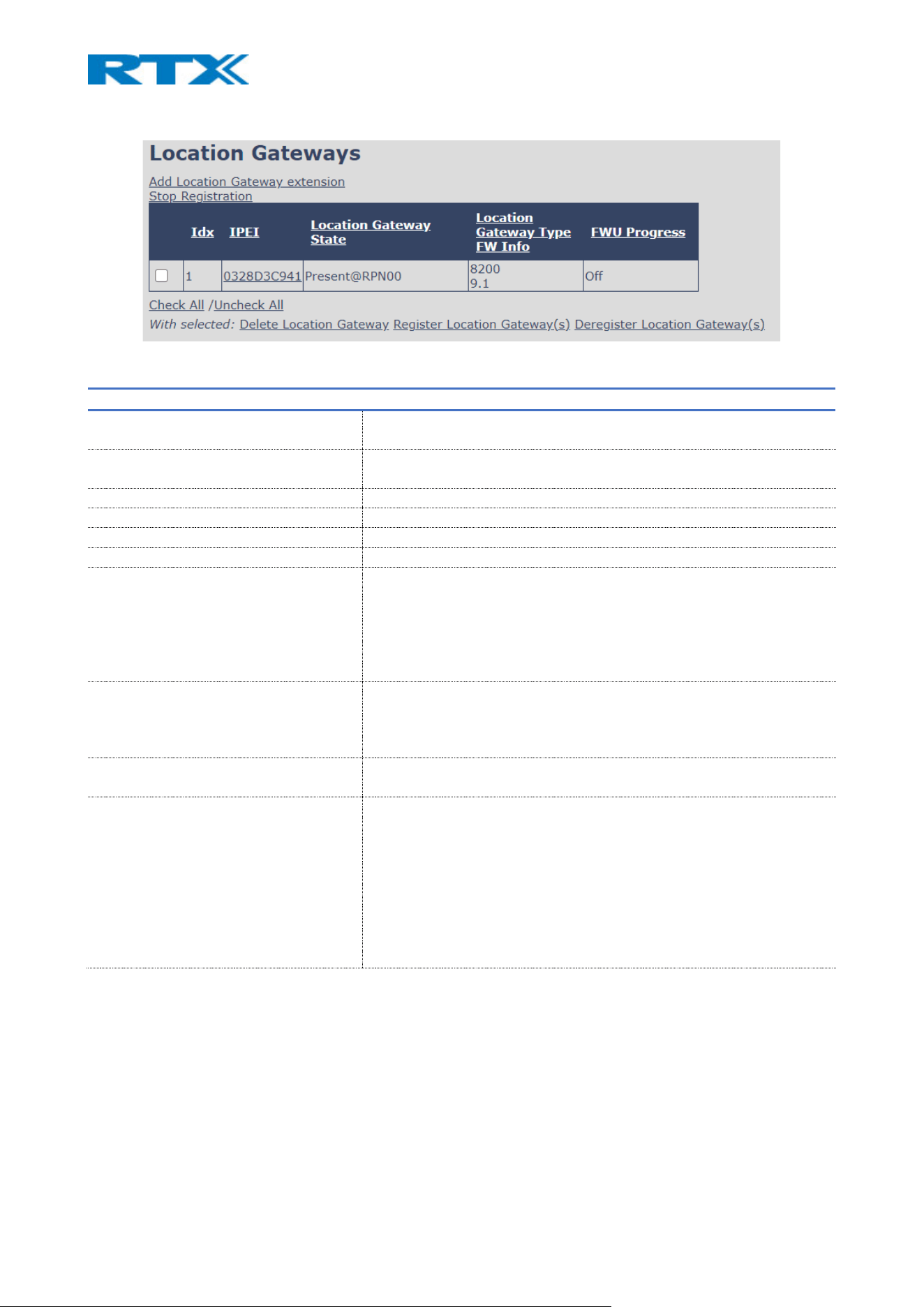
Figure 32 Location Gateways page
PARAMETER DESCRIPTION
ADD LOCATION GATEWAY EXTENSION Provides access to the Location Gateway editor menu, where the
administrator can add new devices
STOP REGISTRATION Manually stops DECT registration mode for the system. This prevents
location gateways to register to the system
DELETE LOCATION GATEWAY Deregisters and deletes the device from the VoIP base station
REGISTER LOCATION GATEWAY(S) Enable registration mode for the selected location gateway entries.
DEREGISTER LOCATION GATEWAY(S) Deregister the selected location gateway(s), but do not delete the entry
IDX Index of the location gateway
IPEI The IPEI of the location gateway. In general, this must not be changed
manually. If IPEI is left at FFFFFFFFFF, any location gateway can register
at this index. Else, only the location gateway with the specified IPEI
number can register to the VoIP system
NOTE: If selected, the editor’s menu will open
LOCATION GATEWAY STATE The state of the location gateway:
Present@RPNxx: The location gateway is DECT located at the base with
RPNxx
Enabled: The slot is open for location gateway registration
LOCATION GATEWAY TYPE
FW INFO
Name of the location gateway type
Firmware version of the location gateway
FWU PROGRESS Possible FWU progress states:
Off: Means that the software version is specified to 0 = fwu is off
Initializing: Means that the firmware is starting and the progress is 0%.
X%: Firmware ongoing
Verifying X%: Firmware writing is done and now it is verifying before
the swap
FWU complete: Upgrade is complete for the location gateway(s):
Error: Not able to firmware upgrade the device (e.g. file not found, file
not valid etc.)
7.1.10 Headset base
This menu is visible only if the “Headset base” feature is enabled on the Management page. Similar to the
Extensions menu, this page provides information about the registered headset base devices and allows the
registration of new ones. A screenshot of the page can be seen below (Fig.31), followed by a table with a
description of the available options.
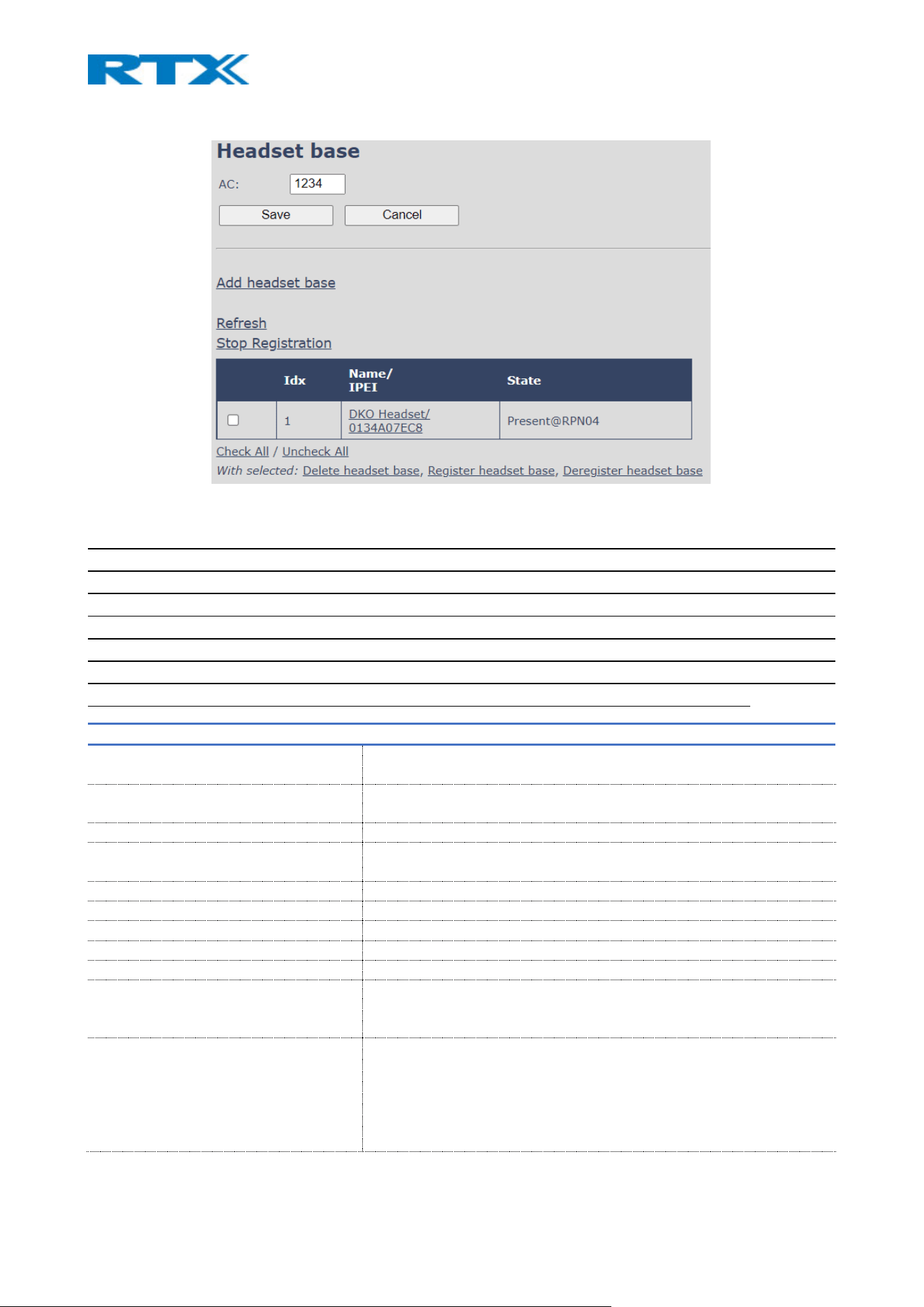
Figure 33 Headset base page
IMPORTANT: Both the headset base and the headset can be SIP registered to the VoIP System. However,
depending on which device is SIP registered, the headset has a different behavior. If the headset base is
registered to a SIP account, then the headset can be used in multiple environments – both in VoIP System
and normal network. This means that a user can receive VoIP calls and at the same time use the headset for
various PC applications, such as listening to music or talking via a softphone (Microsoft Teams). Moreover,
these functionalities are available while moving around the VoIP system. However, if the headset is SIP
registered as a standalone (without the headset base), then it can be used only for VoIP calls on the system.
For more details on the Headset base and Wireless headsets, please refer to the relevant guide.
PARAMETER DESCRIPTION
AC Access code used when registering a headset base
Default value: 0000
ADD HEADSET BASE Provides access to the Headset base editor menu, where the
administrator can add and edit devices
REFRESH Refreshes the page
STOP REGISTRATION Manually stops DECT registration mode for the system. This prevents
headset bases to register to the system
CHECK ALL / UNCHECK ALL Check/Uncheck all headset base entries in the table
DELETE HEADSET BASE Deregisters and deletes the device from the VoIP base station
REGISTER HEADSET BASE Enable registration mode for the selected headset base entries
DEREGISTER HEADSET BASE Deregister the selected headset base(s), but do not delete the entry
IDX Index of the headset base
NAME / IPEI Headset base’s name/IPEI. IPEI is a unique DECT identification number.
NOTE: If selected, the editor’s menu will open
STATE The state of the headset base:
Present@RPNxx: The headset base is DECT located at the VoIP base
with RPNxx
Removed: The headset base has been out of sight for a specified
amount of time (~one hour).
Enabled: The slot is open for headset base registration on this index

7.1.10.1 Headset base editor menu
The editor menu is presented to the administrator as soon as the “Add headset base” link is selected. The
available settings are further explained in the following table.
PARAMETER DEFAULT VALUES DESCRIPTION
NAME Empty The name displayed on the headset base overview page
IPEI FFFFFFFFFF The IPEI of the headset base. In general, this must not be changed
manually. If IPEI is left at FFFFFFFFFF, any headset base can register
at this index. Else, only the headset base with the specified IPEI
number can register to the VoIP system
TERMINAL No Terminal This setting enables the administrator to assign a SIP account to the
headset base. The following options are available:
No Terminal: No SIP account assigned
Terminal Idx x: A free extension/SIP account slot which can be
assigned to the headset base
New Terminal: Creates a new terminal/extension slot on the
Extensions page with the IPEI of the headset base. The
administrator needs to edit the extension details in order to SIP
register the headset base.
NOTE: By SIP registering the headset base, the user can use the
headset both for VoIP calls and for other PC applications (such as
music, softphones, etc.)
7.1.11 Country
This menu allows the configuration of the country, language and time server for the base station (Fig.32).
The country setting controls the in-band tones used by the system.
The time server supplies the time used for data synchronisation in a multi/dual cell configuration. As such, it
is mandatory to have the time server set for a multi/dual cell configuration, else the system will not work
properly. Furthermore, the time server is used in the debug logs and SIP traces, along with determining the
time to check for new configuration and firmware files.
NOTE: It is not necessary to set the time server for standalone base stations (optional).
NOTE: When the time server parameters are modified/changed, synchronisation between base stations can
take up to 15 minutes before all of them are synchronised (depending on the number of base stations in the
system). Changing time settings will require a reboot of the system.
NOTE: By checked time zone and DST, the parameters in the Time section will be discarded.
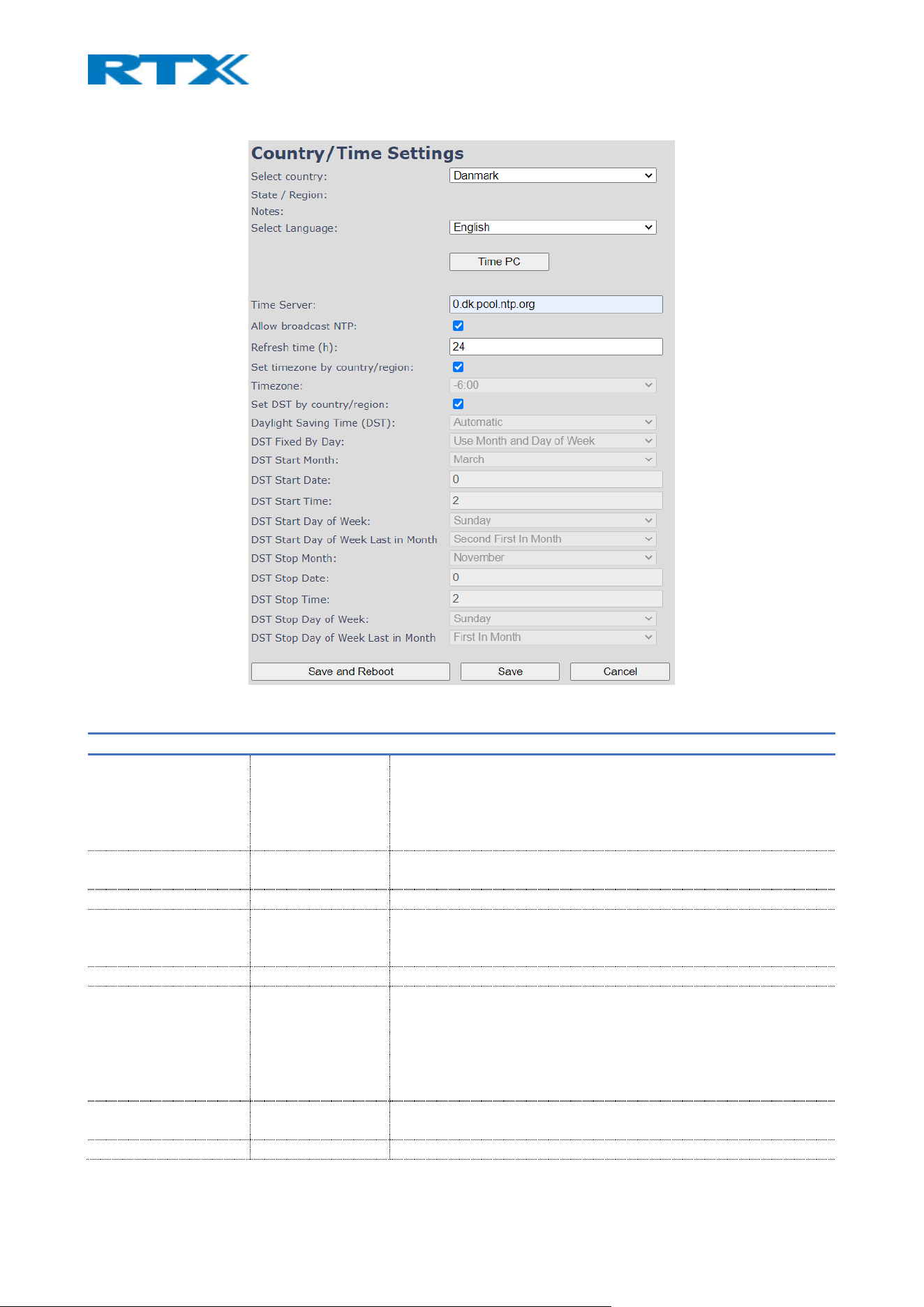
Figure 34 Country/Time settings page
PARAMETER DEFAULT VALUES DESCRIPTION
SELECT COUNTRY US/Canada Supported countries: Australia, Belgium, Brazil, Canada, Denmark,
Germany, Greece, Spain, France, Ireland, Italy, Luxembourg,
Netherlands, New Zealand, Norway, Portugal, Russia, Switzerland,
South Africa, Finland, Sweden, Thailand, Turkey, United Kingdom,
US, Austria, China
STATE / REGION N/A Displayed only when country selection is US, Canada, Australia or
Brazil
NOTES N/A Displayed only when country selection is US, Canada or Russia
SELECT LANGUAGE English Web interface language. Available languages: English, Danish,
Italian, Turkish, German, Portuguese, Croatian, Serbian, Slovenian,
Dutch, French, Spanish, Russian, Polish.
TIME PC BUTTON N/A Use the current time from your PC as a time server
TIME SERVER Empty DNS name or IP address of an NTP server.
Enter the IP/DNS address of the server that distributes reference
clock information to its clients, including base stations, handsets,
etc.
Valid Input(s): AAA.BBB.CCC.DDD or URL (e.g. time.server.com)
Currently, only Ipv4 address (32-bit) is supported.
ALLOW BROADCAST
NTP
Checked If checked, the time server is used.
REFRESH TIME (H) 24 The window time in hours in which the time server refreshes.

Valid Inputs: positive integer
SET TIMEZONE BY
COUNTRY/REGION
Checked If checked, the country setting is used
TIMEZONE 0 Refers to local time in GMT or UTC format.
Min: -12:00
Max: +13:00
SET DST BY
COUNTRY/REGION
Checked If checked, the country setting is used.
DAYLIGHT SAVING
TIME (DST)
Disabled The system administrator can enable or disable DST manually.
Automatic: Enter the start and stop dates if this option is selected
DST FIXED BY DAY Use Month and
Day of week
You determine when DST changes. Choose the relevant date or day
of the week, etc. from the drop-down menu.
DST START MONTH March The month that DST begins
Valid Input(s): Gregorian months (e.g. January, February, etc.)
DST START DATE 0 Numerical day of the month DST comes to effect when DST is fixed
to a specific date
Valid Inputs: positive integer
DST START TIME 2 DST start time in the day
Valid Inputs: positive integer
DST START DAY OF
WEEK
Sunday Day within the week DST starts
DST START DAY OF
WEEK, LAST IN
MONTH
Second First in
Month
Specify the week for DST to start.
DST STOP MONTH October The month that DST stops.
DST STOP DATE 0 The numerical day of the month that DST turns off.
Valid Inputs: positive integer (1 to 12)
DST STOP TIME 2 The time-of-day DST stops
Valid Inputs: positive integer (1 to 12)
DST STOP DAY OF
WEEK
Sunday The day of the week DST stops
DST STOP DAY OF
WEEK LAST IN MONTH
First in Month The week within the month that DST will turn off.
7.1.12 Security
This section describes how the system secures information and enforces protection over access,
communication, and storage of user data.
Security Handling
The system stores and processes a range of security-relevant assets, including:
• User credentials: PINs, SIP/LDAP/XSI usernames and passwords
• Certificates and encryption keys: Used for TLS authentication, encrypted communication, and
DECT/Bluetooth pairing
• Personal identifiers: Including contact names, phone numbers, text messages, call logs, and IP addresses
associated with communication sessions or phonebook synchronization

These assets are protected through access control mechanisms and, where applicable, encrypted storage.
Event logging is applied to key operations to ensure traceability. Sensitive credentials and certificates are
partly stored in secure memory areas inaccessible to standard interfaces.
Security Compatibility Notes
To support legacy compatibility and flexible deployment, the system includes several protocol options that
may reduce the overall security posture:
• DECT DSC is supported to maintain compatibility with legacy devices. The system uses 64-bit DECT
encryption.
• MD5-based authentication is supported for legacy SIP infrastructure. TLS is used for transport security where
available.
• 802.1X network authentication supports both MD5 and TLS. It is recommended to configure TLS-based
authentication to ensure improved security.
• Push-to-Talk (PTT) uses a non-encrypted DECT UDP audio channel, which may be subject to interception.
• TFTP is available for configuration and directory provisioning. This protocol does not provide authentication
or encryption and may allow interception or modification of transmitted data.
• Alarm integration is available for configuration and directory provisioning. This protocol does not provide
authentication or encryption and may allow interception or modification of transmitted data.
• HTTP is supported as an alternative to HTTPS for management file access. HTTP is unencrypted and
vulnerable to interception and tampering.
Security Advisory: Use of these protocols may lower confidentiality and integrity protections. Administrators
are advised to enforce secure alternatives (e.g., HTTPS, TLS, EAP-TLS) wherever available.
This menu takes into consideration the main security aspect of the system. It is used to load certificates,
change web authentication and configure a secure web server (Fig.33). More details about the options can
be found in the following table.
There are, however, some security settings which must be managed on other pages. For example, to setup
secure firmware and configuration file download, the Management page must be used. Another example is
securing the SIP and RTP, which are server dependent, meaning that the administrator must use the Servers
page in order to configure them.
The Identity and Trusted certificates are preserved during upgrade. However, during a factory default, all
certificates that have been installed via the web server, will be deleted. The base does not include any default
trusted certificates. In addition to certificate removal, the system erases stored SIP credentials, user
configuration, logs, and private keys during a factory reset. These are purged to prevent recovery through
typical operation or reboot procedures.
NOTE: There is no expiration notification for the certificates.
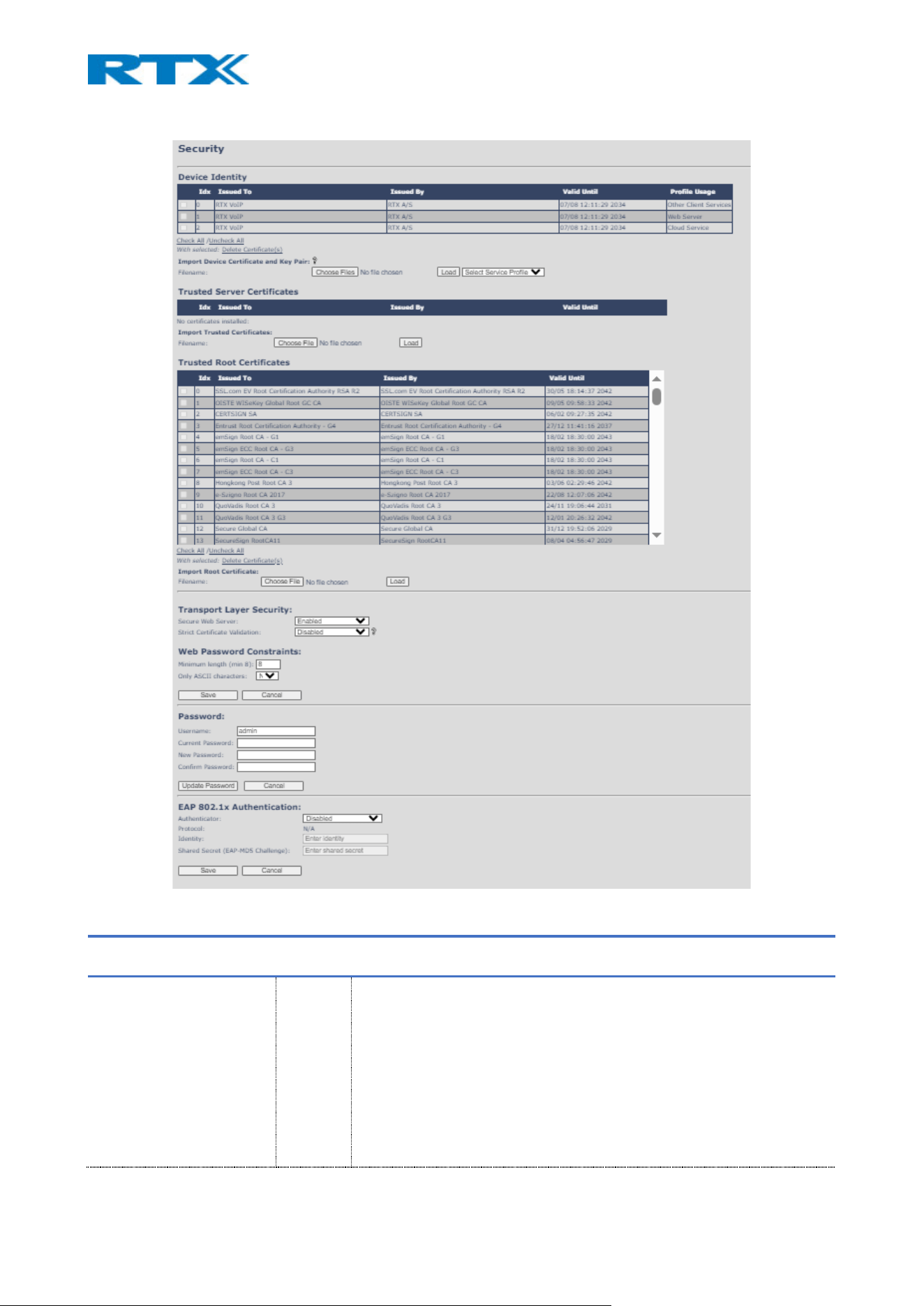
Figure 35 Security page
PARAMETER DEFAULT
VALUES
DESCRIPTION
DEVICE IDENTITY N/A The base stations support 3 different certificates
1: Other Client Service – The certificate needs to be pre-loaded during
production and cant be changed. If no
certificate is loaded during production, a
dummy (self-signed) certificate generated on
device and used as both client and server
identity.
2: Web Server – This certificate is used for Secure Web Server access
(HTTPS).
3: Cloud Service – Certificate need to access RTX Cloud service.

NOTE: Certificate is not cleared during factory reset.
IMPORT DEVICE
CERTIFICATE AND KEY PAIR
N/A The certificate and private key used by the base when acting as a server
or when the server requires client authentication in the TLS handshake
procedure.
When a Device Certificate is loaded, you need to select profile usage of
certificated from dropdown. ( Web Server or Cloud Service)
The same certificate and key pair cannot be used for more than one
profile.
IMPORT TRUSTED
CERTIFICATES
N/A Intermediate certificates (non-root certificates) trusted by the base. Used
to validate a received certificate chain (or a chain of trust) in scenarios,
where only the root certificate is sent by the server during the SSL
handshake procedure.
IMPORT ROOT
CERTIFICATE
N/A Root certificates (self-signed) trusted by the base. Used to validate
received root certificates sent by the server during the SSL handshake
procedure.
SECURE WEB SERVER Enabled Allows the user to enable/disable the use of Secure Web Server.
NOTE: TLS 1.2 is supported for SIP, Web, and firmware communication.
Session identifiers and timestamps are used to prevent message replay or
session hijack attacks, where supported by the server.
STRICT CERTIFICATE
VALIDATION
Disabled
If enabled, the certificate validity period will be checked. Therefore, the
certificates which the base will receive from the server, must be valid and
loaded into the system. If no valid matching certificate is found during the
TLS connection establishment, the connection will fail.
If the feature is disabled, all certificates received from the server will be
accepted.
NOTE: It is important to use correct date and time of the system when
using trusted certificates. In case of undefined time/date, the certificate
validation can fail. TLS cipher suites use AES-128 or higher encryption and
SHA-256 for data integrity. Forward secrecy and RFC-compliant suites are
recommended where server compatibility allows.
WEB PASSWORD
MINIMUM LENGTH
8 The minimum possible value is 8. User can extend that if desired up to 15.
NOTE: Login interfaces enforce minimum length and complexity
requirements to protect against brute-force attacks. Incorrect login
attempts may be rate-limited by provisioning systems to prevent denial-
of-service.
ONLY ASCII CHARACTERS No Allows the user to define if the password can use only ASCII characters.
USERNAME admin Can be modified to any supported character and number.
Maximum characters: 15
CURRENT PASSWORD admin Type in the current web-authentication password.
NEW PASSWORD* Empty Change to new password.
Maximum characters: 15
CONFIRM PASSWORD Empty Confirm the password to ensure that there are no extra or less characters.
AUTHENTICATIOR Disabled When enabled it activates EAP 802.1x Authentication.
PROTOCOL N/A
When the EAP Authentication is enabled, the protocol is automatically
set. IT can be EAP-TLS Authentication or EAP-MD5 Challenge.

IDENTITY
Enter
identity
This is the name the user chooses for the authentication.
SHARED SECRET (EAP-MD5
CHALLENGE)
Enter
shared
secret
Required when using EAP-MD5 Challenge protocol.
NOTE: From v700 the user is forced to change their password on first login as well as after a password reset
by the administrator.
NOTE: In a chained setup of multi-cell or dual cell enabled bases, the bases may be provisioned using config
files. If these config files do not set the credentials, then ONLY the synchronization primary base in the chain
will be prompted for password change. It is therefore the responsibility of configurator to ensure
credentials are correct either from synchronization primary base or via the configuration file! The other
bases in the chain will be inaccessible until provisioned password is changed. Attempting to access with
default credentials from a none-primary base will put following syslog: “Account locked due default
credentials”.
NOTE: In v700 hashed passwords are introduced. Downgrade from this version is not recommended.
However, if necessary, to downgrade from V700, the following guide should be followed:
- Downgrade to V610B1-V610B3 requires to first downgrade to a FW higher than or equal to V610B4 AND
lower than V700.
- Downgrade to V420-V530 requires first to downgrade to V530B10 or higher V530 FW versions.
*Password valid special signs: @/|<>-_:.!?*+#
*Password valid numbers: 0-9
*Password valid letters: a-z and A-Z
7.1.13 Central directory
The SME VOIP system supports three types of central directories - local central directory, LDAP and XML
directory. Depending on the selected “Location” type, different configurable parameters will be displayed
(Fig.34). However, all directories’ caller id look up is made with a match for 6 digits of the phone number.
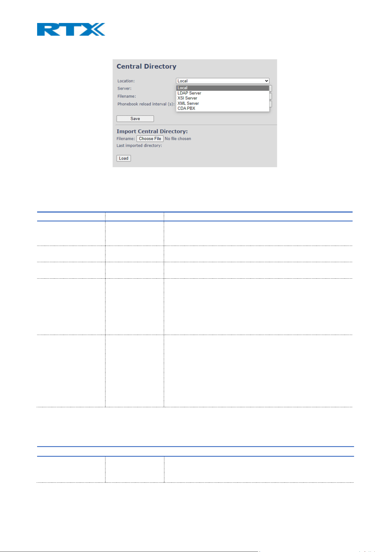
Figure 36 Central Directory
7.1.13.1 Local Central Directory
For details on the contact list structure, please refer to 9.1 Contact list structure.
PARAMETER DEFAULT VALUES DESCRIPTION
LOCATION Local Drop-down menu to select between local central directory, LDAP
based central directory and XML server
NOTE: Changes to this feature require base station reboot.
SERVER Empty The parameter is used if the directory file is located on a server
Valid inputs: aaa.bbb.ccc.ddd or <url>
FILENAME Empty The name of the file with the addresses. This parameter is used if
the directory file is located on a server.
PHONEBOOK RELOAD
INTERVAL (S)
0 This parameter is controlling the reload interface of a phonebook in
seconds. The feature is for automatic reload of the base phonebook
file from the server with intervals. It is recommended to specify a
conservative value to avoid overload of the base station.
With a default value setting 0, the reload feature is disabled.
NOTE: We recommend 86400 seconds (24 hours) as a minimum
reload interval.
IMPORT CENTRAL
DIRECTORY
Empty This feature enables the administrator to import a central directory
file with .csv/.txt/.xml file format. This feature is using a browse file
approach. After file selection, the load button must be pressed to
load the file. The system supports only the original .csv format.
Please note, that some excel .csv formats are not the original .csv
format.
The central directory feature can handle up to 3000 contacts (Max
file size 100kb).
7.1.13.2 LDAP
To reach the LDAP configuration menu, select “LDAP server” from the drop-down menu (Fig.33).
PARAMETER DEFAULT VALUES DESCRIPTION
CENTRAL DIRECTORY
LOCATION
LDAP Server Drop-down menu to select between local central directory, LDAP
based central directory and XML server. “LDAP Server” is displayed
when LDAP server is selected.

SERVER Empty IP address of the LDAP server.
Valid Inputs: AAA.BBB.CCC.DDD or <URL>
TLS SECURITY Disabled If enabled, it uses encrypted TCP, else – UDP
Note: In most cases LDAP over TLS is running on port 636
SORT BY commonName Select the way the contacts are to be sorted. Choose between
common name, given name and surname
PORT Empty The server port number that is open for LDAP connections
Note: In most cases LDAP over TLS is running on port 636
SBASE Empty Search Base. The input depends on the configuration of the LDAP
server. Example of the setting is OU=umber,DC=umber,DC=loc
LDAP FILTER Empty LDAP Filter is used as a search filter. For example, setting LDAP filter
to (|(givenName=%*)(sn=%*)) the base will use the filter when
requesting entries from the LDAP server. % will be replaced with the
entered prefix, e.g. searching on “J” will give the filter
(|(givenName=J*)(sn=J*)) resulting in a search for given name
starting with a “J” or surname starting with “J”.
BIND Empty The username that will be used when the IP-DECT phone
connects to the server. An example is the following:
CN=Dummy,OU=umber,DC=umber,DC=loc
PASSWORD Empty The password for the LDAP Server
VIRTUAL LIST Disabled If enabled, virtual list searching will be possible
NAME cn The name can be used to specify if sn+givenName or cn (common
name) is returned in the LDAP search results
WORK NUMBER Empty Work number is used to specify the LDAP attribute that will be
mapped to the handset work number
HOME NUMBER Empty Home number is used to specify the LDAP attribute that will be
mapped to the handset home number
MOBILE NUMBER Empty Mobile number is used to specify the LDAP attribute that will be
mapped to the handset mobile number
7.1.13.3 XSI server
To be able to configure the XSI server, select this option from the drop-down menu. It allows the user to
edit directory names and set priority of the directories shown on the handset when entering Central
Directory.
PARAMETER DEFAULT VALUES DESCRIPTION
CENTRAL DIRECTORY
LOCATION
XSI Server Drop-down menu to select between local central directory, LDAP
based central directory and XML server. “XSI Server” is displayed
when XSI server is selected.
SERVER Empty IP address of the XML server.
Valid Inputs: AAA.BBB.CCC.DDD or <URL>
ENTERPRISE Enabled Type of tag for the group/directory
ENTERPRISE
COMMON
Enabled Type of tag for the group/directory
GROUP Enabled Type of tag for the group/directory
GROUP COMMON Enabled Type of tag for the group/directory
PERSONAL Disabled Type of tag for the group/directory
DIRECTORY PRIORITY Listed the inserted
directory names
User can mark a directory name and edit its priority with the “Up”
and “Down” button. It is possible to remove a name by pressing

“Remove” and reset priority to the previous state by pressing
“Reset Priority”
7.1.13.4 XML server
To reach the XML configuration menu, select “XML server” from the drop-down menu (Fig.35). That allows
the user to add an XML server.
PARAMETER DEFAULT VALUES DESCRIPTION
CENTRAL DIRECTORY
LOCATION
XML Server Drop-down menu to select between local central directory, LDAP
based central directory and XML server. “XML Server” is displayed
when XML server is selected.
SERVER Empty IP address of the XML server.
Valid Inputs: AAA.BBB.CCC.DDD or <URL>
NOTE: In firmware version v720b200 and earlier XSI server and XML server are not separate features, and
they can both be edited by selecting the “XML server” option in the drop-down menu.
7.1.14 Dual/Multi cell
The following sub-chapter presents the available settings on the Dual/Multi cell page (Fig.36). These are
divided into several sections, which will be described as follows: Settings for this unit, DECT System settings,
Base station settings, Base station group and DECT chain.
NOTE: To join two or more base stations in a dual/multi cell system, you need to have one extension or
handset added to the system. For further details and a Step-by-Step guide to a multi cell setup, please refer
to 8.1 Multi cell system.
NOTE: B760 base can be added to a multi cell with the old RTX8660 base station and thus, run in a mixed
mode. For further details, please refer to 9.2 B760-RTX8660 Mixed mode.
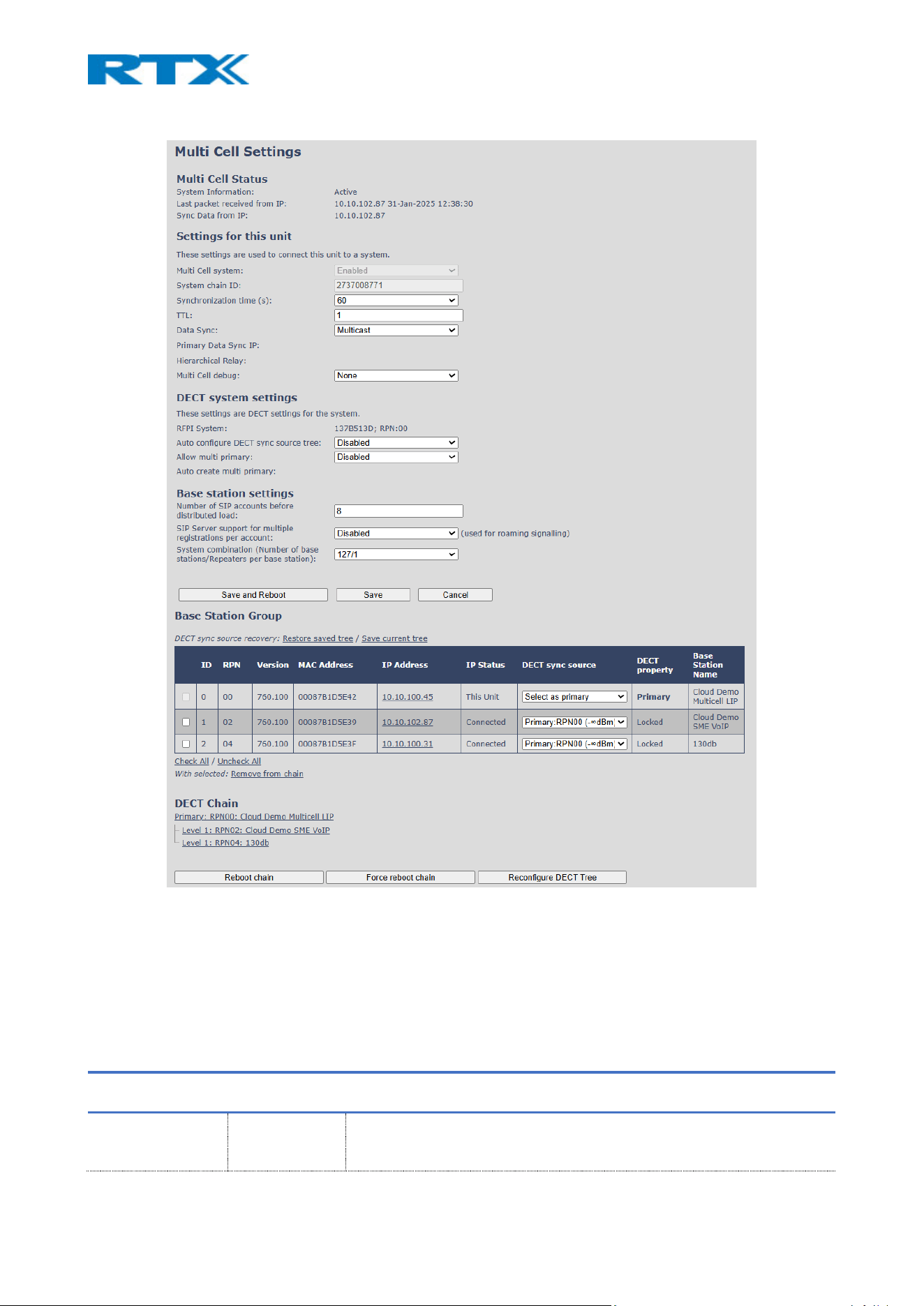
Figure 37 Multi / Dual cell settings page
The dual/multi cell data synchronization status is presented at the top of the page (Fig.35), where “Keep-
alive” means normal operation.
7.1.14.1 Settings for this unit
The following table presents the settings for the specific base station, used to connect it to a system.
PARAMETER DEFAULT
VALUES
DESCRIPTION
DUAL / MULTI CELL
SYSTEM
Disabled Enable this option to allow the base unit to be set in dual/multi cell mode
Valid Inputs: Enable, Disable
Must press Save and Reboot after changing from disabled to enabled.

NOTE: This feature is enabled by default for B700/730
SYSTEM CHAIN ID
Dual cell
Multi cell
2370683830
512
This is an identifier (in string format e.g. 2275) that is unique for a specific
dual/multi cell system. It is a DECT cell identity, allocated to bridge several
bases together in a chain.
The Chain ID is used as a SIP account for check Sync. Therefore, the value
MUST NOT be equal to a used SIP account.
Valid Input: The Web site allows max 5 digits in this field.
NOTE: In a dual cell system (B700/730), the Chain ID cannot be set or
modified by the user. As soon as two bases are connected, the system
automatically changes the default chain ID to a unique identifier.
NOTE: In a multi cell system, the Chain ID is set by the user. The default value
is 512, which means that extension 512 must not be used – unless the chain
ID is modified. When there is a multi cell system up and running, the Chain
ID can be modified by provisioning only.
NOTE: There can be several multi cell systems with the same Chain ID in a
SME network. Up to 24 levels of base station chains are permitted in a setup.
SYNCHRONIZATION
TIME (S)
60 sec This specifies the period in seconds for a base station to synchronize to the
primary base. If no keep-alive packets are received within a period of
2*Synchronization Time(s), the base will be indicated as lost in the multi
cell configuration. The parameter is also used with “Auto create multi
primary” feature from the following configuration settings
NOTE: This feature is not supported by B700/730
DATA SYNC: Multicast Select between “Multicast” or “Peer to Peer” data synchronization mode.
The multicast feature uses UDP, along with the port range: 49200 – 49999
and IP range: 224.1.0.0 – 225.1.0.0. The used port range and IP addresses
are calculated from the Chain ID.
NOTE: For multicast operation make sure that Multicast/IGMP is enabled
on your switch(es), else use Peer-to-peer mode.
PRIMARY DATA
SYNC IP
Empty IP of the base station data sync source – the base handling the data
synchronization.
When using multicast, this base IP is selected automatically.
The data sync feature uses the port range: 49200 – 49999
When using Peer-to-Peer mode, the IP of the base used for data sync
source MUST be defined.
NOTE: Using Peer-to-Peer mode with version below V306 limits the
system’s automatic recovery feature, meaning that there is no automatic
recovery of the data sync. source in Peer-to Peer-mode.
HIERARCHICAL
RELAY
empty This feature is available when Peer-to-peer data sync is chosen.
The feature allows the user to distribute the data sync load between
multicell base stations.
Recommended usage based on the number of base stations in a system:
• If the system has less than 100 base stations, relay should be set
to 0

• If the system has 100 or more base stations, relay should be set
to 3
NOTE: Currently other values than 0 and 3 SHOULD NOT BE USED!
DUAL / MULTI CELL
DEBUG
None Enable this feature, if you want the system to catalogue low level
dual/multi cell debug information or traces.
Available Options:
Data Sync: Writes header information for all packets, received and sent, to
be used to debug any special issues. Generates a lot of syslog signaling and
is only recommended to enable shortly when debugging.
Auto Tree: Writes states and data related to the Auto Tree Configuration
feature.
Both: Both Data Sync and Auto Tree are enabled.
NOTE: Must only be used for debug purpose and not enabled on a normal
running system
7.1.14.2 DECT system settings
The following table presents the DECT settings for the whole system.
PARAMETER DEFAULT
VALUES
DESCRIPTION
DECT SYSTEM RFPI Values may
vary
This is a radio network identity accessed by all base units in a specific multi
cell system. It is composed of five octets and has five different variables
combined.
RFPI Format: XX XX XX XX XX (where XX are HEX values)
AUTO CONFIGURE
DECT SYNC
SOURCE TREE
Enabled Enable this to allow the system to automatically synchronize the
dual/multi cell chain/tree.
NOTE: Must be enabled in order to allow a new primary to recover in case
the original primary goes into faulty mode.
ALLOW MULTI
PRIMARY
Disabled This feature is used for multi-location setups. Allows two or more primary
bases in the same system.
The two cells will be unsynchronized, and handover will not be possible.
NOTE: To run a system with two separate primaries in two locations “Allow
multi primary” and “Auto configure DECT sync source tree” must be
enabled. To add the second primary, the slave must manually be
configured as primary. Alternatively, the “Auto create multi primary” must
be enabled as well.
NOTE: Not supported on Dual cell.
AUTO CREATE
MULTI PRIMARY
Disabled This feature is used for multi-location setups. It automatically creates
primary bases if they cannot connect to the main chain. For instance,
if you have a site with an established multi cell system and would like to
extend the system to another location, the added base will be
automatically created as primary, if it cannot reach the chain from the first
location. This means that both sites would be on the same system, but
have different primaries, due to the range between them.

7.1.14.3 Base station settings
The following table lists the rest of the base station settings for the dual/multi cell system.
PARAMETER DEFAULT
VALUES
DESCRIPTION
NUMBER OF SIP
ACCOUNTS BEFORE
DISTRIBUTED LOAD
10 The maximum number of handsets or SIP end nodes, that are permitted
to perform location registration on a specific base unit, before load is
distributed to other base units. The parameter can be used to optimize
the handset distribution among visible base stations.
Permitted Input: Positive Integers (e.g. 6)
NOTE: A maximum of 10 simultaneous calls can be routed through each
base unit in a multi cell setup.
NOTE: This feature is not supported by B700/730
SIP SERVER
SUPPORT FOR
MULTIPLE
REGISTRATIONS
PER ACCOUNT
Disabled Disable this option to make it possible to use the same extension (i.e.
SIP Account) on multiple phones (SIP end nodes). These phones will ring
simultaneously for all incoming calls.
Available options:
Disabled: No SIP de-registration will be made when a handset
roams to another base station
Enabled: The old SIP registration will be deleted with a SIP
de-registration, when a handset roams to another base
station
SYSTEM
COMBINATION
(NUMBER OF BASE
STATIONS/REPEATERS
PER BASE STATION):
50/3 Select between basic base configurations.
50/3: 50 bases and 3 repeaters
127/1: 127 bases and 1 repeater
254/0: 254 bases and 0 repeater
NOTE: If the system combination is set to 127/1 or 254/0, you can still
register more than one repeater, but it will not get a DECT Sync source
and will have no function.
NOTE: This feature is not supported by B700/730
7.1.14.4 Base station group
The following table aims to introduce you to the “Base station group” table indications. The group table
lists the base stations that are in a dual/multi cell system and provides information for each one of them.
PARAMETERS DESCRIPTION
RESTORE SAVED TREE Restores the current tree to the last saved version. May be triggered from any base
station. However, it is recommended to restore it from the same base station that it
was saved from before.
SAFE CURRENT TREE Saves the current tree on all base stations that are fully active and synchronizes the
data in the multicell.
ID Base unit identity in the chained network.
Permitted Output: Positive integers
RPN The Radio Fixed Part Number is an 8-bit DECT cell identity allocated by the installer. The
allocated RPN within the SME must be geographically unique.
Permitted Output: 0 to 255 (DEC) OR 0x00 to 0xFF (HEX)
VERSION Base station’s current firmware version.

Permitted Output: positive Integers with dot (e.g. 480.1)
MAC ADDRESS Contains the hardware Ethernet MAC address of the base station. It varies from base
station to base station.
IP ADDRESS Base station’s current IP address
IP STATUS Current base station behavior in the SME network.
Possible Outputs
Connected: The relevant base station(s) is online and connected to the network
Connection Loss: Base station unexpectedly lost connection to the network
This Unit: Indicates the current base station which http Web Interface is currently
accessed
DECT SYNC SOURCE With setting “Auto configure DECT sync source tree” set to “Enable”, this tree will
automatically be generated. If manually configured, the administrator should choose
the relevant “multi cell chain” level he wants and organize the base units. Maximum
number of “multi cell chain” levels is 24.
Format of the selection: “AAAAAxx: RPNyy (-zz dBm)”
AAAAA: indication of sync. source for the base. Can be “Primary” or “Level xx”
xx: Sync. source base sync. level
yy: Sync. source base RPN
zz: RSSI level of sync. source base seen from the actual base
“(Any) RPN”: When a base is not synchronized to another base. State after reboot of
chain.
DECT PROPERTY Base station characteristics in connection to the current dual/multi cell network.
Possible Output(s):
Primary: Main base station to which all other nodes in the chain synchronize to.
Locked: The base unit is currently synchronized and locked to the master base unit.
Searching: Base unit in the process of locating to a Master/Slave as specified in DECT
sync source
Free Running: A locked base unit that suddenly lost synchronization to the Master.
Unknown: No current connection information from specific base unit
Assisted lock: Base has lost DECT sync. source and Ethernet is used for synchronization
Sync. Lost: Handset has an active DECT connection with the base, but the base has lost
DECT sync. source connection. The base will continue working as long as the call is
active and will go into searching mode when call is stopped.
BASE STATION NAME Name from management settings.
NOTE: It is recommended to do a "Save current tree" before starting the FWU process and a "Restore saved
tree" when all bases are updated since the time used in the FWU process may be different in a large
multicell system, and the DECT tree will therefore be updated several times during the FWU process.
7.1.14.5 DECT chain
Below the “Base station Group” table is the DECT Chain tree. The DECT Chain tree is a graphical presentation
of the “Base station Group” table levels and connections. If any repeaters are present, they are highlighted
in green and if some units are part of the base group but not present in the tree, they are highlighted in red
(Fig.36).

Figure 38 DECT chain visualization
7.1.15 Multi Zone
The B760 base station supports a Multi Zone feature, which allows different multi cell systems to be
interconnected via zones. This means that each zone is a separate multi cell system. Such setup allows the
handsets to be used across all zones but configured only in one of them. The following sub-chapter presents
the available settings on the page (Fig.37) These are divided into several sections, which will be described as
follows – Settings for this unit, DECT system settings and Multi zone System. The settings can be configured
both via the webpage and via provisioning. For a more detailed guide on configuring and using the feature,
please refer to the RTX VoIP DECT System Traffic Planning and Deployment.pdf.
NOTE: This feature is not supported by B700/730
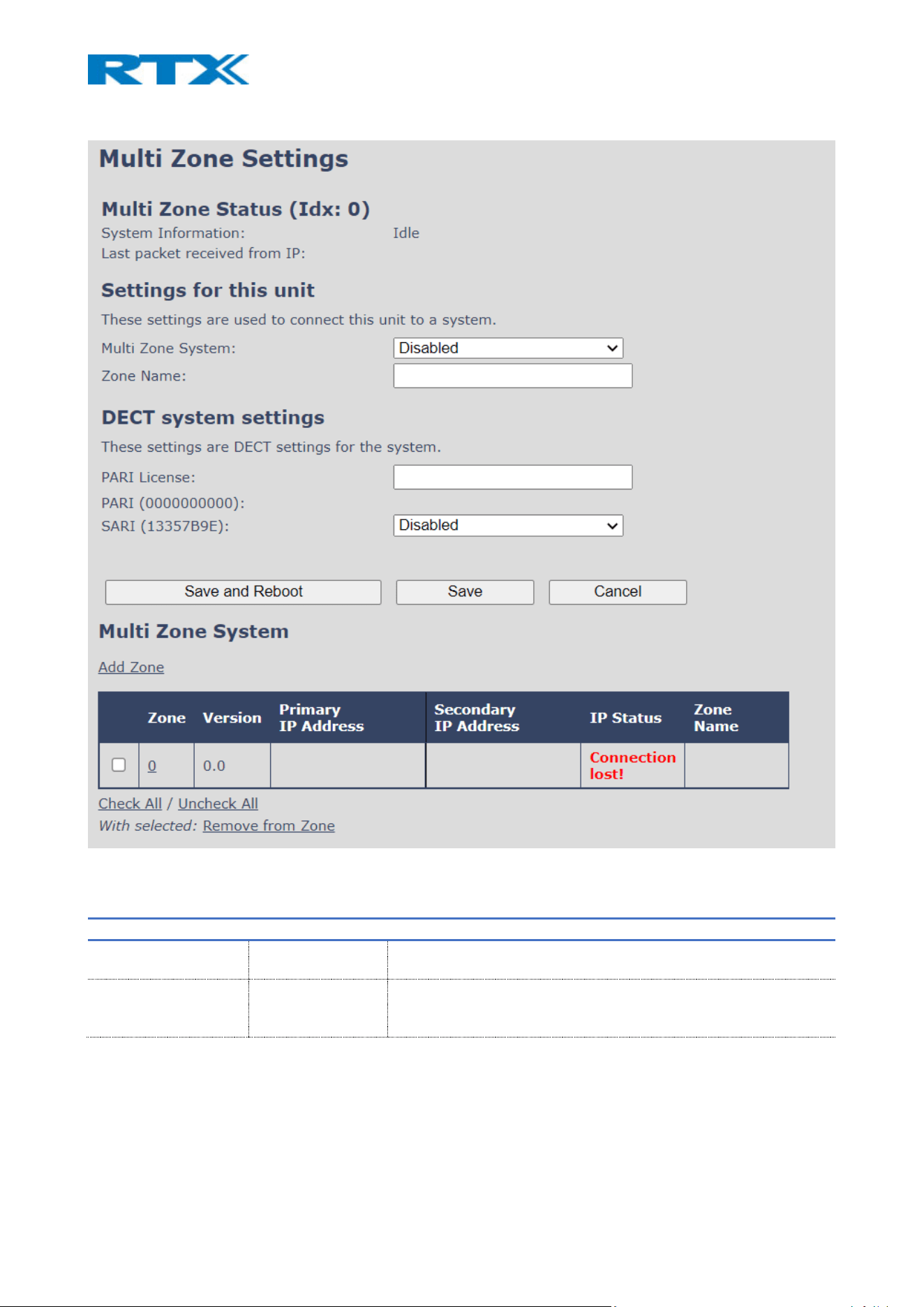
Figure 39 Multi Zone settings page
7.1.15.1 Settings for this unit
PARAMETER DEFAULT VALUES DESCRIPTION
MULTI ZONE SYSTEM Disabled An On/Off type of setting, which will enable/disable the Multi Zone
feature
ZONE NAME Empty Type in the name of the Zone
NOTE: The setup should start with Zone 0
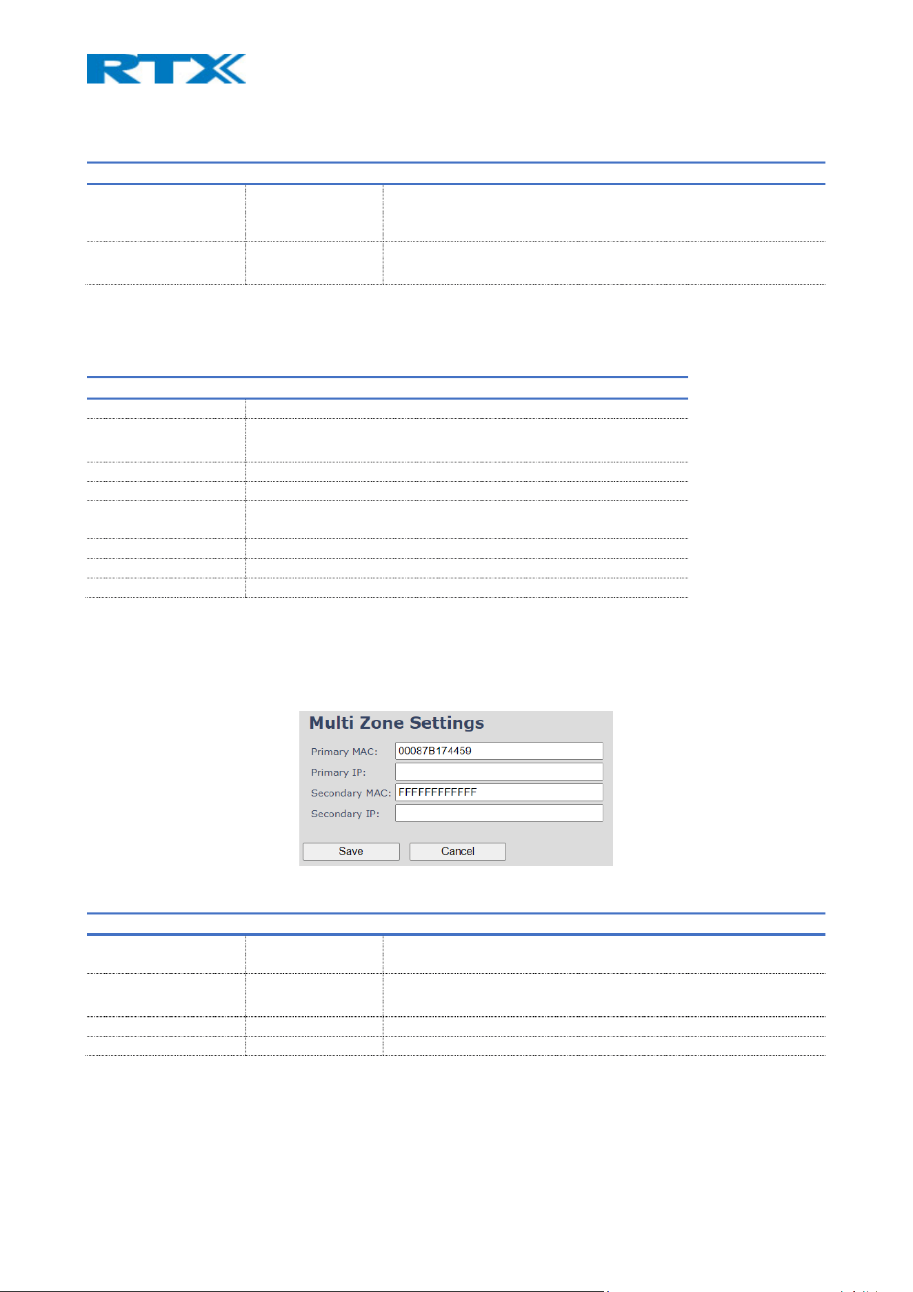
7.1.15.2 DECT system settings
PARAMETER DEFAULT VALUES DESCRIPTION
PARI LICENSE 0000000000
(Empty)
The PARI value should be manually typed ONLY for Zone 0
NOTE: The PARI value should be purchased from RTX
SARI Disabled The SARI value is automatically configured
7.1.15.3 Multi Zone System
The following list aims to introduce you to the Multi Zone System table indications.
PARAMETER DESCRIPTION
ADD ZONE Provides access to the editor menu, where you can add a new zone
ZONE The zone identity in the system
Permitted input: Positive integers
VERSION The zone’s current firmware version
PRIMARY IP ADDRESS The IP address of the Primary base of the zone
SECONDARY IP
ADDRESS
The IP address of the Secondary base (Primary Backup) of the zone
IP STATUS The zone’s current behavior on the system
ZONE NAME The name of the zone
REMOVE FROM ZONE Remove the selected zones from the multi zone system
7.1.15.4 Add zone editor menu
By clicking “Add zone”, a separate editor page opens (Fig.38), which parameters are further explained in
the following table.
Figure 40 Add zone editor page
PARAMETER DEFAULT VALUES DESCRIPTION
PRIMARY MAC Varies from device
to device
The MAC address of the primary base station
PRIMARY IP Empty The IP address of the primary base station
SECONDARY MAC FFFFFFFFFFFF The MAC address of a secondary (backup) base station
SECONDARY IP Empty The IP address of the secondary (backup)base station
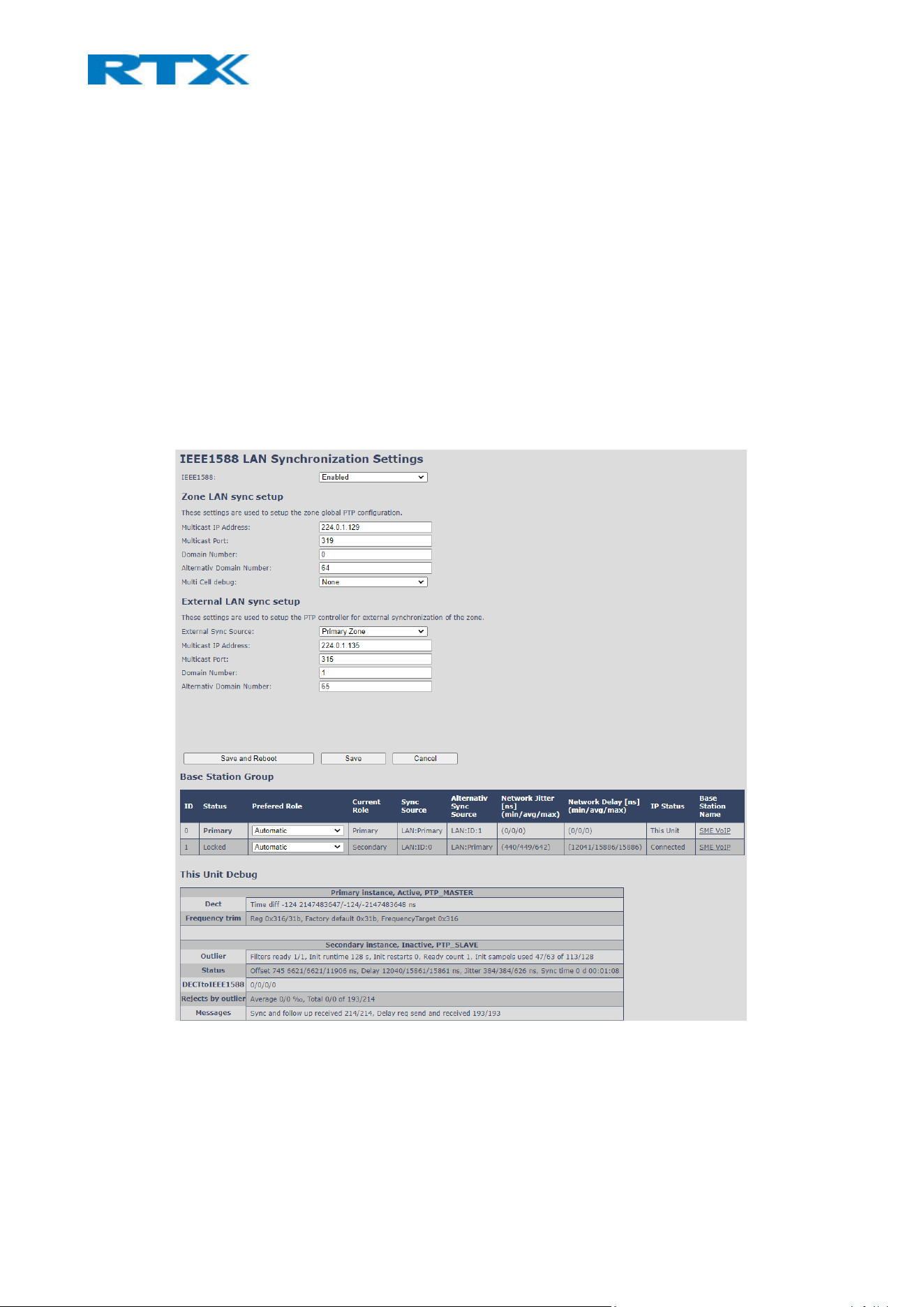
7.1.16 LAN Sync
The B760 base station supports the LAN sync feature, which allows data synchronization over the network,
instead of Over-the-air. This feature, specified by the IEEE1588 standard, has the advantage of providing a
larger coverage installation option for places where the bases cannot “see” each other.
The following sub-chapter presents the available settings on the LAN sync page (Fig.39). These are divided
into several sections, which will be described as follows – IEEE1588 feature, Zone LAN Sync setup, External
LAN Sync setup, Base Station Group and This Unit Debug. To secure a good user experience, settings are kept
to a minimum and are all available to be configured both via the webpage and via provisioning. Before
configuring the LAN sync, the administrator must be aware of the network requirements in order to minimize
the impact from other devices on the network. Therefore, please refer to the RTX VoIP DECT System Traffic
Planning and Deployment .pdf for more details on the LAN sync configuration and usability.
NOTE: This feature is not present in B700/730
Figure 41 LAN Sync page

7.1.16.1 IEEE1588 feature
The initial setting of the page provides the option to enable / disable the LAN Sync feature for the device.
PARAMETERS DEFAULT VALUES DESCRIPTION
IEEE1588 Disabled
An On/Off type of setting, which will enable/disable the LAN
synchronization option
7.1.16.2 Zone LAN sync setup
These settings cover the global configuration of the synchronization in a zone.
PARAMETERS DEFAULT VALUES DESCRIPTION
MULTICAST IP
ADDRESS
224.0.1.129
This setting defines the IP address where to listen for IEEE1588 PTP
packages (IP address of the multicast group). The IP must be the same for
all devices in the specific zone.
NOTE: This should only be changed in case other IEEE1588 equipment is on
the network using this specific IP address.
NOTE: The IP address must start with 224.0.xx.xx and this cannot be
changed.
NOTE: Before setup, make sure no other devices are using the given IP. This
means that each zone should have a different IP!
MULTICAST
PORT
319
Define the port which the system will communicate on (where to listen for
the IEEE1588 PTP messages). The port must be the same for all devices in
the specific zone.
NOTE: This should only be changed in case other IEEE1588 equipment on
the network is using this specific port.
NOTE: Each zone must have a different port
DOMAIN
NUMBER
0
This setting selects the domain number, which is the preferred method to
divide the IEEE1588 PTP messages into zones in IEEE 1588-2008.
Valid input: 0-127
ALTERNATIVE
DOMAIN
NUMBER
64
Alternative domain is only used in case the primary sync source from the
main domain fails. If so, the base station will sync to the alternative
domain.
NOTE: It must NOT have the same value as the domain number.
Valid input: 0-127
MULTI CELL
DEBUG MODE
None
This feature should be enabled if one wants the system to catalogue low
level multi cell debug information or traces.
NOTE: Must only be used for debug purpose and not enabled on a normal
running system
Available Options:

Data Sync: Writes header information for all sent and received packets to
be used to debug specific issues. Generates a lot of Syslog signaling and is
only recommended to enable shortly when debugging.
Auto Tree: Writes states and data related to the Auto Tree Configuration
feature.
Both: Both Data Sync and Auto Tree are enabled.
IEEE1588 Debug: Writes IEEE1588 debug information to the syslog
7.1.16.3 External LAN sync setup
The “External LAN Sync setup” covers the configuration of an external (multi-level) synchronization. This
means that, in order to support more than 250 Base stations in a system, it is necessary to use multi-level
synchronization. This feature is used to define the Primary zone to which all the other zones will sync.
PARAMETERS
DEFAULT
VALUES
DESCRIPTION
EXTERNAL SYNC
SOURCE
Disabled Enable the feature by choosing one of the options below:
Primary zone configuration
Secondary zone configuration
In a default setup, Zone 0 is set as Primary zone and the rest of the zones are
configured as Secondary zone.
MULTICAST IP
ADDRESS
224.0.1.129 To listen for IEEE1588 PTP packages, the IP address should be defined
NOTE: This should only be changed in case other IEEE1588 equipment is on the
network using this specific IP address.
NOTE: The IP address must start with 224.0.xx.xx and this cannot be changed.
NOTE: Before setup, make sure no other devices are using the given IP.
MULTICAST
PORT
319 Define the port on which the system will listen to IEEE1588 PTP messages
NOTE: This should only be changed in case other IEEE1588 equipment is on the
network using this specific port.
DOMAIN
NUMBER
1
This setting selects the domain number, which is the preferred method to divide
the IEEE1588 PTP messages into zones in IEEE 1588-2008.
Valid input: 0-127
NOTE: The input must NOT be the same as the one used in the previous feature
“Zone LAN Sync setup”
ALTERNATIVE
DOMAIN
NUMBER
65
Alternative domain is only used in case the primary sync source from the main
domain fails. If so, the base station will sync to the alternative domain.

NOTE: The input must NOT have the same value as the “Domain number” from
the previous parameter and must NOT be used in the “Zone LAN Sync setup”
feature.
7.1.16.4 Base station group
The Base station group lists various parameter settings for the base stations and allows the administrator to
check the status information for the whole system.
PARAMETERS DESCRIPTION
ID Base unit identity in the chained network.
Permitted Output: Positive Integers
STATUS Base station characteristics in connection to the current multi cell network.
Possible Output(s):
Connecting: The base unit is in the process of locating a Master/Slave as specified in “Sync
source”
Locked: The base unit is currently synchronized and locked to the master base unit
Free Running: IEEE master is found and is DECT synchronizing
PREFERED ROLE Disabled: Disable the feature
Primary: The base station that is used for main sync; only one primary is allowed to the
system
NOTE: It is recommended to use base stations that are closer to the backbone as primary
Secondary: Base stations that will never be selected as primary. They become slaves
Automatic: System finds primary sync source – it allows the system to decide the role of
the base
Alt. Primary: Backup for primary base station in case it fails; only one redundant sync.
master is allowed in the system
CURRENT ROLE The current role of the base station
Possible Output(s):
Disabled: Dispalyed when LAN Sync is disabled for the device
Primary: Main base station which all other nodes in the chain synchronize to
Alternate: Fallback base station for redundancy, which will be used in case the primary
base is offline
Secondary: Secondary base stations which are synchronized to the primary or alternate
base
Initializing: Initial state

SYNC SOURCE
Shows to which base station this specific device is synchronized and indicates if it is via LAN
or DECT
Indications:
ID: the device with ID from the current list
RPN: the DECT ID used from the Over-the-air symbolization.
ALT. SYNC SOURCE Alternative sync source in case main sync source fails
NETWORK JITTER
[NS]
(MIN/AVG/MAX)
Measures how the IEEE1588 packets are received, the lower the Jitter is the better
Min: Displays the minimum jitter average between primary and slave
Avg: Displays the average jitter between primary and slave
Max: Displays the maximum jitter average between primary and slave
NETWORK DELAY
[NS]
(MIN/AVG/MAX)
Measures the time it takes an IEEE packet to travel from Primary to Slave base station in
ns.
Min: Displays the minimum average delay between primary and slave
Avg: Displays the average delay between primary and slave
Max: Displays the maximum average delay between primary and slave
IP STATUS Current base station behavior in the SME network.
Possible Output(s):
Connected: The relevant base station(s) is online and connected to the network
Connection Loss: Base station unexpectedly lost connection to the network
This Unit: Current base station which http Web Interface is currently being accessed
BASE STATION
NAME
Name from the Management page
7.1.16.5 This unit debug
This section displays debug information, which is used only by RTX to debug LAN Sync network issues. In case
debug is needed, send this information to RTX support team. The debug data is not synced between the
bases.
7.1.17 Repeaters
This section presents and describes the different parameters available in the Repeaters configuration page
(Fig.40).
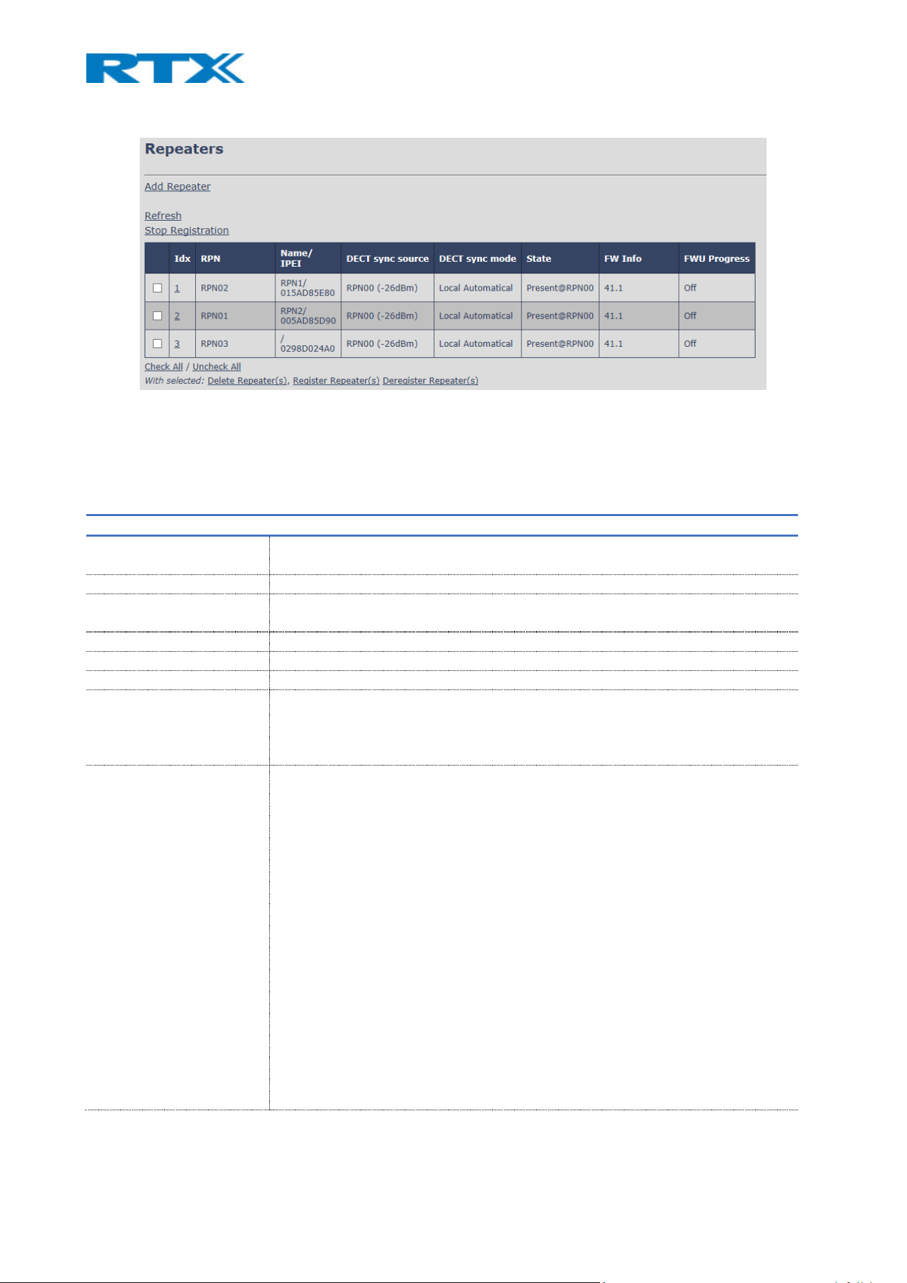
Figure 42 Repeaters page
Depending on the base station type and system, the number of supported repeaters can vary (see 2.3.1 Base
stations). For a multi cell system with B760 base stations, the number of repeaters, allowed on each base
station, is defined on the Multi cell page (7.1.14 Dual/Multi cell).
PARAMETERS DESCRIPTION
ADD REPEATER Provides access to the “Add Repeater” editor menu, where new devices can be
added
REFRESH Refreshes the page
STOP REGISTRATION Manually stops DECT registration mode of the system. This prevents repeaters to
register to the system
DELETE REPEATER(S) Deregisters and deletes the device from the VoIP base station
REGISTER REPEATER(S) Enable registration mode for the selected repeater entries.
DEREGISTER REPEATER(S) Deregister the selected repeater(s), but keep the entry
IDX Repeater unit identity in the chained network.
Permitted Output: Positive Integers
NOTE: If selected, the editor’s menu will open
RPN The Radio Fixed Part Number (RPN) is an 8-bit DECT cell identity allocated by the
installer. The allocated RPN within the SME must be geographically unique.
Permitted Output: 0 to 255 (DEC) OR 0x00 to 0xFF (HEX)
Allocation of the repeaters to the bases by RPN is done the following way:
The base stations have an RPN identity which is incremented by 2^2 in hex,
meaning that the first base is RPN00, second base is RPN04, etc. The
repeaters’ RPN identification is addressed in between the RPN of the
bases. For example:
Base stations are named RPN00 – RPN04 – RPN08, etc. - jumping 4 numbers each
time (HEX numbers)
Repeaters, which connect to base station RPN00, will be named after RPN01 –
RPN02 – RPN03 (HEX numbers)
Repeaters, which connect to base station RPN04 will be called RPN05 – RPN06 –
RPN07 (HEX numbers).
Etc.

An exception of this rule is when using a multi cell (B760) with a system
combination 127/1. In this case, since there is only 1 repeater allowed per base,
the RPN would increase only by 2. For example:
Base stations are named RPN00 – RPN02 – RPN04, etc. - jumping 2 numbers each
time (HEX numbers)
Repeater, which connects to base station RPN00 will be named after RPN01 (HEX
numbers)
Repeater, which connects to base station RPN02 will be named after RPN03 (HEX
numbers)
Etc.
NAME/IPEI Contains the name and the unique DECT serial number of the repeater. If no name
is given, the field will be empty.
DECT SYNC SOURCE The chain connection to the specific base/repeater unit. Maximum number of
chain levels is 12.
Sync. source format: “RPNyy (-zz dBm)”
yy: RPN of source
zz: RSSI level seen from the actual repeater
DECT SYNC MODE Synchronization type:
Manually: User-controlled by manually assigning the repeater’s “RPN” and “DECT
sync source” RPN
Local Automatical: Auto -controlled by detecting the base station with the best
signal and auto assigning an RPN.
STATE
Enabled: The slot is open for repeater registration on this index
Present@unit: The repeater is DECT located at the VoIP base with RPNyy
Removed: The repeater has been out of sight for a specified amount of time (~one
hour).
FW INFO Firmware version of the repeater
FWU PROGRESS Possible FWU progress states:
Off: FWU version is set to 0 - FWU is off
Initializing: FWU is starting and progress is 0%.
X% : Ongoing FWU progress
Verifying X%: FWU writing is done and verifying before the swap
”Conn. term. wait” (Repeater): All FWU is complete and is waiting for connections
to stop before the repeater restarts.
Complete: FWU complete
Error: Not able to FWU upgrade. For example, due to file not found, not valid, etc.
NOTE: If there are unsupported repeaters registered to the base station, the system shows the following
warnings: “System is configured with unsupported repeaters.” and “Reboot is needed for changes to take
effect”.
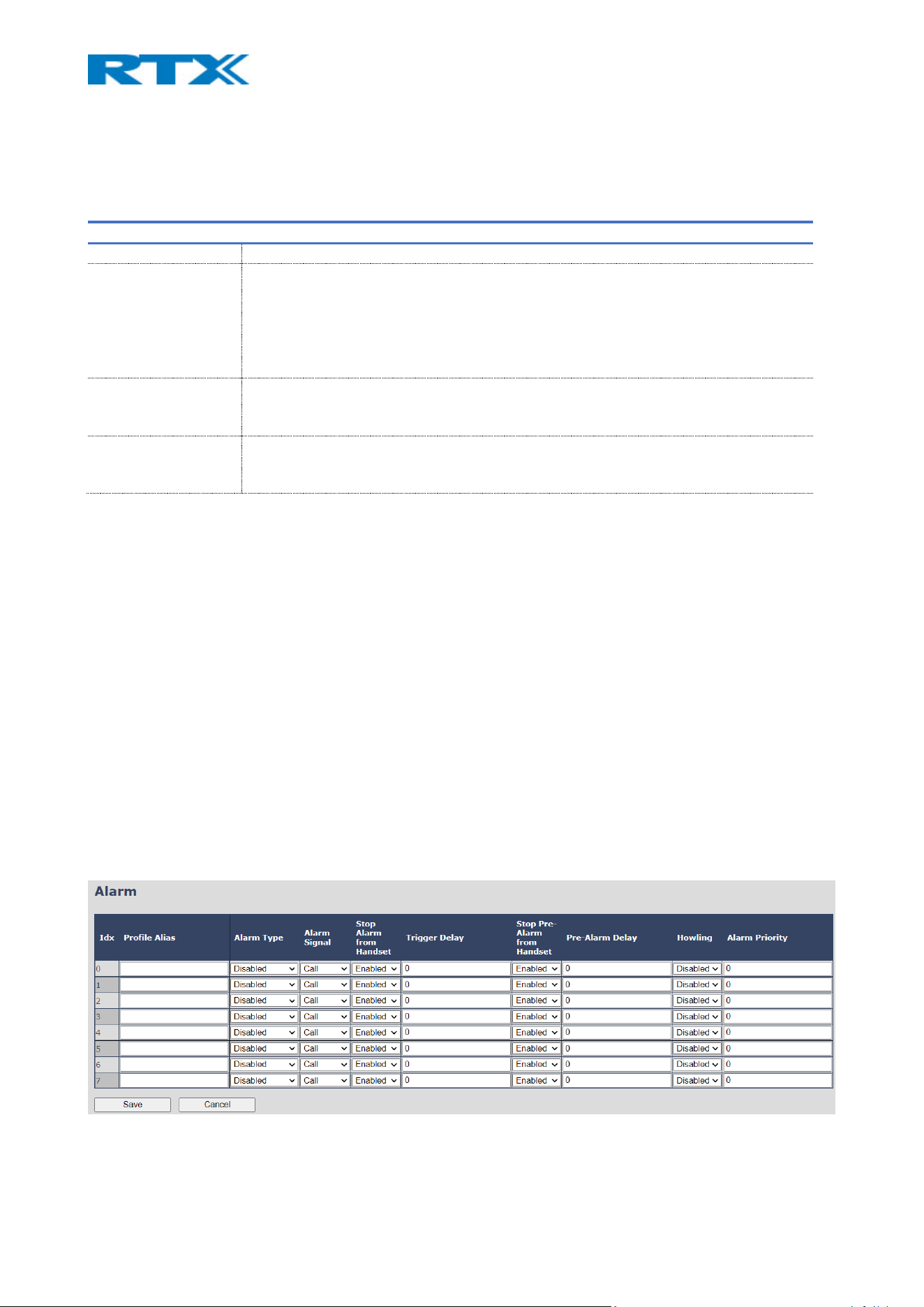
7.1.17.1 Add repeater editor menu
By selecting the “Add repeater” link, a separate editor page opens which parameters are further explained in
the following table.
PARAMETERS DESCRIPTION
NAME Repeater’s name. If no name is specified, the field will be empty
DECT SYNC MODE Manually: User-controlled by manually assigning the repeater’s “RPN” and “DECT sync
source” RPN
Local Automatic: Auto -controlled by detecting the base station with the best signal
and auto assigning an RPN.
NOTE: With “Local automatic” mode repeater on repeater (chain) is not supported.
RPN The identity of the repeater
NOTE: This option is visible only if “DECT sync mode” is set to “Manually”
DECT SYNC SOURCE The device (base/other repeater) to which the repeater will connect to
NOTE: This option is visible only if “DECT sync mode” is set to “Manually”
NOTE: A good practice when adding repeaters to a Dual Cell system (B700/730) is to use a manual
registration, because then you can control to which base station the repeater(s) connects to. In this way, the
repeater will also have a static RPN whereas if the repeater is set to automatic sync mode, the RPN may vary
from one registration to another. This is dependent on the repeater which will register to the base first, after
for example a base reboot. If at least 1 repeater is set to manual sync mode, it is strongly recommended to
have all repeaters in the setup configured the same way, in order to make sure that the repeaters connect to
the desired RPN.
7.1.18 Alarm
The Alarm page allows the administrator to enable different types of alarms for the handsets (Fig.41). Up to
eight alarm profiles can be configured on this page, which later can be assigned to the handsets. The following
section aims to describe the available settings. For further details about the alarms and use case examples,
please refer to Appendix 9.4 Alarm characteristics. For an alarm configuration guide, please refer to 8.5
Alarms.
Figure 43 Alarm page

PARAMETERS DESCRIPTION
IDX Indicates the index number of a specific alarm.
PROFILE ALIAS A user-friendly name to help identify the different alarm profiles
ALARM TYPE The alarms are dependent on the type of handsets being used.
RTX8631/RTX8632/RTX8633:
Alarm button
RTX8830:
Alarm button
Man Down
No Movement
Running
Pull Cord
NOTE: RTX8430, RTX8431 and RTX8436 do not support the alarm feature
NOTE: RTX8630 cannot send alarms, but it can receive them
ALARM SIGNAL The way the alarm is signaled when received on the handset.
Message: A text message via an alarm server.
NOTE: If a handset supports Bluetooth and Receiver mode is enabled, the beacon data will
be included in the message. For more details, please go to 7.1.4 Handsets.
Call: An outgoing call to the specified emergency number (see 7.1.4 Handsets).
STOP ALARM
FROM HANDSET
Enable/Disable the possibility to stop/cancel the alarm from the handset.
TRIGGER DELAY The possibility to delay an alarm in a specific number of seconds. This is the period from
when the alarm has been fired until the handset displays a pre-alarm warning. If this
setting is set to 0, there will be no pre-alarm warning, and the alarm will be signaled
immediately. The alarm algorithm typically needs about 6 sec. to detect, for example,
Man down, etc.
STOP PRE-ALARM
FROM HANDSET
Enable/Disable the possibility to stop/cancel the pre-alarm from the handset.
PRE-ALARM DELAY The period from displaying the pre-alarm warning message until the actual alarm is
signaled. The maximum value is 254.
HOWLING Enable/Disable howling on the handset when the alarm is signaled. If disabled, only the
configured signal is sent (call or message).
ALARM PRIORITY Define the priority of the alarm
7.1.18.1 Use of Emergency alarms
As described above, it can be configured if it should be possible to stop an alarm from the handset. If the
possibility to stop an alarm from the handset is disabled, it is ensured that an alarm is not stopped before
someone at e.g., an emergency center, has received the alarm and reacted upon it.
The behavior of a handset, when an alarm “is sent”, depends on the configured Alarm Signal:
• Call: When the Alarm Signal is configured as “Call”, the handset will make a call to the specified
emergency number, and the alarm will terminate when the call is ended. If it is not allowed to stop
the alarm from the handset, it will not be possible to terminate the call from the handset, and the
alarm will be considered as stopped only when the remote end (e.g. the emergency center)
terminates the call.
• Message: When the Alarm Signal is configured as “Message”, the handset will send an alarm message
to the specified alarm server and enable auto answer mode. This means that if the receiver responds
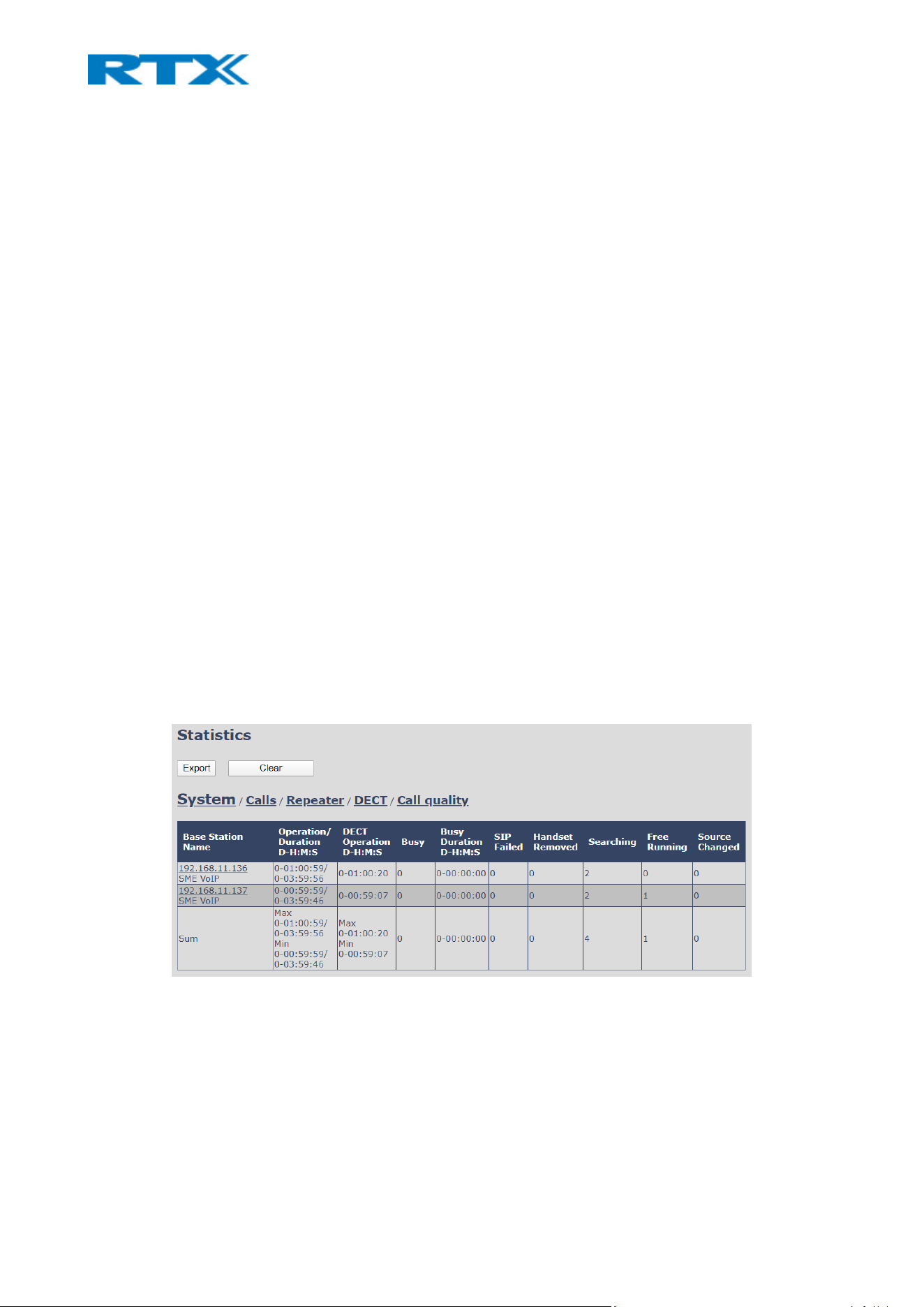
to the alarm message by calling the alarm initiator, the handset will immediately answer the call and
allow the person in danger to talk to the other party.
If Howling is enabled on the sender part, the handset will also start the Howling tone. An alarm is
considered as stopped, depending on its configuration (for ex. after confirming that the alarm has
been received)
All type of alarms have the same priority. This means that once an alarm is active, it cannot be overruled by
another alarm until the first one has been stopped. However, if the alarm is not yet active, i.e. if it is in “pre-
alarm” state and an alarm configured with no pre-alarm is fired, then the new alarm will become active and
stop the pending alarm.
Alarms with no pre-alarm are considered important, and there is no possibility to cancel them before they
are sent. Therefore, alarms with no pre-alarm are given higher priority than alarms in pre-alarm state.
7.1.19 Statistics
This menu provides different kind of system information (Fig.42). It includes the following five administrative
pages, which are described accordingly.
1. System
2. Calls
3. Repeater
4. DECT data
5. Call quality (NOTE: B700/730 does not support this feature)
All five views have an embedded export function, which allows the administrator to export all data to
common separated file. By pressing the clear button, all data in the system is cleared.
Figure 44 Statistics page

7.1.19.1 System
The table below describes the available parameters on this page.
PARAMETERS DESCRIPTION
BASE STATION NAME Base IP address and base name (name can be edited in the Management page)
OPERATION/DURATION
D-H:M:S
Operation: Operation time for the base since last reboot.
Duration: Operation time for the base since the last reset of statistics, or firmware
upgrade.
DECT OPERATION
D-H:M:S
Displays information about Days, Hours, Minutes and Seconds that the base station has
been running
BUSY Displays the number of times the base has been busy.
BUSY DURATION
D-H:M:S
Displays the total time a base has been busy for speech (8 or more calls active).
SIP FAILED Displays the number of times a SIP registration has failed
HANDSET REMOVED Displays the number of times a handset has been marked as removed
SEARCHING Displays the number of times a base has been searching for its sync source
NOTE: This is not supported by B700/730
FREE RUNNING Displays the number of times a base has been free running (explained below)
NOTE: This is not supported by B700/730
SOURCE CHANGED Displays the number of times a base has changed sync source
NOTE: This is not supported by B700/730
IEEE1588 SYNC LOST Counts how many times a base has lost sync with both “Sync Source” and “Alternative
Sync Source” (the primary and alternative primary base)
NOTE: This parameter is visible only if IEEE1588 is enabled
IEEE1588 PRIMARY
LOST
Counts how many times a base has lost sync with the “Sync Source” (the primary base).
NOTE: This parameter is visible only if IEEE1588 is enabled
7.1.19.1.1 Free running
The state Free running is NOT an error state, but a simple trigger state, indicating that some changes must
be made to ensure continuous DECT synchronization.
The state Free running informs the application that the base has not received any synchronization data from
its synchronization source in the last 10 seconds. There could be several reasons for this:
1. The two bases are using the same DECT slots and therefore cannot see each other.
2. Many simultaneous voice or data calls.
3. A sudden change of the environment (e.g., closing a fire door)
4. Distortion of DECT frequency (around 1.8MHz) either by other DECT systems, or other equipment.
When the Free running state is triggered, several recovery mechanisms can be activated:
1. Move the DECT slot to avoid using the same base state as its synchronization source
2. Use information from all other base stations to monitor how they are seeing the current device in
the DECT air. This can be marked by changing to state Assisted lock
The state Assisted lock can be stabile for a long time and usually can change to state Locked again. The state
Free Running can also change back to state Locked again.

If the base is in state Free running and the synchronization source base is not seen and no data is available
for the assisted lock mechanism, the base station will change to a new state after two minutes:
1. If the base station does NOT have any active calls, the base will change to state Searching.
2. If the base station has an active call, this base will change to state Sync lost. After the call is
released, the state will change to state Searching.
7.1.19.2 Calls
The table below describes the available parameters on this page.
PARAMETERS DESCRIPTION
BASE STATION NAME Base IP address and base name (name can be edited in the Management page)
OPERATION
TIME/DURATION
Operation: Operation time for the base since last reboot.
Duration: Operation time for the base since the last reset of statistics, or firmware
upgrade.
COUNT Counts the number of calls on the base.
DROPPED Displays the number of active calls that were dropped.
E.g., if a user has an active call and walks out of range, the call will be counted as a
dropped call. An entry is stored in the syslog when a call is dropped.
EMERGENCY CALLS Counts the number of emergency calls on the base
CALL DROPS DUE TO
EMERGENCY CALL
Displays the number of active calls that were dropped due to an emergency call
EMERGENCY CALLS
REJECTED
Displays the number of emergency calls that were rejected
NO RESPONSE Displays the number of calls that have no response. E.g., if an external user tries to
make a call to a handset that is out of range, the call is counted as no response. An
entry is stored in the syslog when a call is in no response.
DURATION Displays the total time that calls are active on the base.
ACTIVE Displays the number of active calls on the base station (not active DECT calls, but
active calls). The max number of active calls per base/system can be seen in 2.3.1
Base stations
MAX ACTIVE Displays the maximum number of calls that have been active at the same time.
CODEC Logging and count of used codec types on each call.
HANDOVER ATTEMPT
SUCCESS
Counts the number of successful handovers.
HANDOVER ATTEMPT
ABORTED
Counts the number of failed handovers.
AUDIO PACKET LOSS Counts the number of times where audio connection was not established.
7.1.19.3 Repeater
The table below describes the available parameters on this page.
PARAMETERS DESCRIPTION
IDX/NAME Base IP address and base name (name can be edited in the Management page)
OPERATION
D-H:M:S
Total operation time for the repeater since last reboot
BUSY Displays the number of times the repeater has been busy.
BUSY DURATION
D-H:M:S
Displays the total time a repeater has been busy for speech (5 or more calls active).
MAX ACTIVE Displays the maximum number of calls that have been active at the same time.
SEARCHING Displays the number of times a repeater has been searching for its sync source

RECOVERY Displays the number of times a repeater has been in recovery mode.
(In case the sync source is not present anymore, the repeater will lock on to another base
or repeater, and display recovery mode)
SOURCE CHANGED Displays the number of times a repeater has changed its sync source
WIDE BAND Displays the number count of wideband calls on the repeater
NARROW BAND Displays the number count of narrow band calls on the repeater
7.1.19.4 DECT
The table below describes the available parameters on this page.
PARAMETERS DESCRIPTION
FREQUENCY Displays the number of the DECT slot frequency
SLOTX Displays the number of connections that have been active on each frequency
7.1.19.5 Call quality
The table below describes the available parameters on this page.
NOTE: B700/730 does not support this feature
PARAMETERS DESCRIPTION
BASE STATION
NAME
Base IP address and base name (name can be edited in the Management page)
TYPE Call: Amount of calls on the base, measured in RTP connections.
Relay conn: Amount of calls created on one base, and then handed over to another. This
results in the initial base having a relay connection.
CALL COUNT Displays the number of calls
LOCAL/REMOTE
SIDE
These two parameters indicate the call quality.
Local: Quality of the call from this end (this base)
Remote: Quality of the call from “the other end” – The base the other handset is
connected to
JITTER[MS] Measures how the RTP packets are received.
The lower the Jitter, the better.
ROUND TRIP
LATENCY [MS]
Measures the time it takes for RTP packets to reach its destination.
PACKET LOSS [%] Displays the percentages of lost packets
R-VALUE A way to measure call quality, from 0-120. Refer to the user satisfaction rate table below
MOS-VALUE Measures subjective call quality for a call. MOS scores range from one, unacceptable, to 5
- excellent. Refer to the user satisfaction rate table below
VOIP calls often are in the 3.5 to 4.2 range
USER SATISFACTION LEVEL MOS R-value
MAXIMUM USING G.711 4.4 93
VERY SATISFIED 4.3-5.0 90-100
SATISFIED 4.0-4.3 80-90
SOME USERS SATISFIED 3.6-4.0 70-80
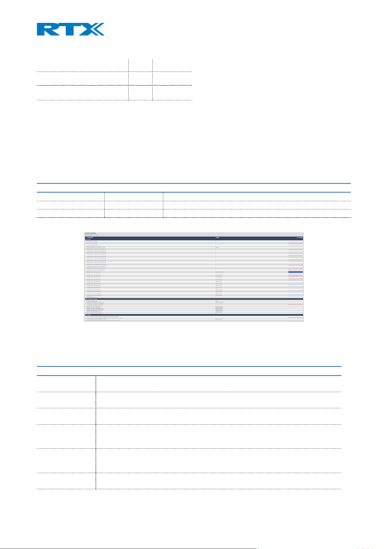
7.1.20 Generic statistics
This page provides further system information, distributed among five categories in the form of a table
(Fig.43). The categories and the related display output are described accordingly. The statistics are base-
related.
The menu has an embedded “Export all fields” function, which allows the administrator to see the statistics
hour by hour. By pressing the “Reset all statistics” button, all data in the system is cleared.
TABLE PARAMETER DEFAULT VALUE DESCRIPTION
PARAMETER Varies Headline of the different category statistics
VALUE Varies Varies from point to point
24 HR DATA Varies Data from the last 24 hours
Figure 45 Generic Statistics page
7.1.20.1 DECT Statistics
The table below describes the available parameters under this category
PARAMETERS DESCRIPTION
TOTAL NUMBER OF
DLC INSTANCE
The lifetime total count of instantiated DLC instances.
MAX CONCURRENT
DLC INSTANCES
The lifetime highest concurrent count of instantiated DLC instances.
CURRENT NUMBER
OF DLC INSTANCES
The current count of instantiate DLC instances.
TOTAL NUMBER OF
TIMES IN MAX DLC
INSTANCES IN USE
The number of times we reach the currently highest count of DLC instances.
TOTAL TIME SPEND
IN MAX DLC
INSTANCES IN USE
The time we have spent in the highest concurrent number of instantiated DLC instances.
AVERAGE
FREQUENCY X
The average use of frequency number X. The value is 100 if the frequency is fully used by
a slot in the measured time frame.
MANY USERS DISSATISFIED 3.1-3.6 60-70
NEARLY ALL USERS DISSATISFIED 2.6-3.1 50-60
NOT RECOMMENDED 1.0-2.6 Less than 50

USAGE THIS HOUR
(MAX 100 PER
SLOT)
AVERAGE EVEN
SLOT USAGE THIS
HOUR (MAX 100
PER SLOT)
The average use of even numbered slots.
AVERAGE ODD
SLOT USAGE THIS
HOUR (MAX 100
PER SLOT)
The average use of odd numbered slots.
PERCENTUAL TIME
OF X SLOTS USED
THIS HOUR
The percentual time that X number of DECT slots are used during the given hour
(compared to other slot counts).
TOTAL CHO
SUCCESS
The number of times connection handover is successfully made.
TOTAL NUMBER OF
FORCED PP MOVES
The lifetime total count that this base forces PP moves.
7.1.20.2 DECT Synchronization statistics
The table below describes the available parameters under this category.
PARAMETERS DESCRIPTION
CURRENT
SYNCHRONISATION
STATE
The current DECT sync state (e.g. Master, Searching, Free Running, etc).
CURRENT
SYNCHRONISATION
CHAIN
The current DECT sync source (base station ID) of this device
TIMESTAMP FOR
LAST CHANGED
SYNCHRONISATION
CHAIN
Timestamp of the last time this base changed DECT sync source.
HOURLY NUMBER OF
SYNCHRONISATION
CHAIN CHANGES
The number of times this base changed DECT sync source in the current hour.
TOTAL NUMBER OF
SYNCHRONISATION
CHAIN CHANGES
The lifetime total count of times this base changed DECT sync source.
TOTAL TIME IN SYNC
STATE: X
The total time that the base has been in one of the following states:
Master/ Locked/ Free Running/ Locked Assisted/ Sync Lost/ Searching/ Unknown
LAST REPORTED
SYNC INFORMATION
The time when the base received the last sync information
7.1.20.3 RTP Statistics
The table below describes the available parameters under this category
PARAMETERS DESCRIPTION
TOTAL RTP CONNECTIONS (INCLUDING
CONNECTION TYPE INFORMATION, E.G.
EXTERNAL, RELAY, RECORDING)
The lifetime total count of instantiated RTP streams.

MAX CONCURRENT RTP CONNECTIONS
(INCLUDING CONNECTION TYPE
INFORMATION, E.G. EXTERNAL, RELAY,
RECORDING)
The lifetime highest concurrent count of instantiated RTP streams.
TOTAL TIME SPEND IN MAX RTP
CONNECTIONS IN USE
The time spent in the highest concurrent count of instantiated RTP
streams.
CURRENT RTP CONNECTIONS
(INCLUDING CONNECTION TYPE
INFORMATION, E.G. EXTERNAL, RELAY,
RECORDING)
The current count of instantiated RTP streams.
CURRENT LOCAL RTP CONNECTIONS
CURRENT LOCAL RELAY RTP
CONNECTIONS
CURRENT REMOTE RELAY RTP
CONNECTIONS
CURRENT RECORDING RTP
CONNECTIONS
CURRENT BLACKFIN DSP STATUS Data is only available if DSP module is installed
NOTE: This feature is not present in B700/730
TOTAL NUMBER OF BLACKFIN DSP
RESTARTS
Data is only available if DSP module is installed
NOTE: This feature is not present in B700/730
7.1.20.4 IP-Stack statistics
The table below describes the available parameters under this category:
PARAMETERS DESCRIPTION
TOTAL CONNECTIONS
OPEN
The lifetime total count of used sockets.
MAX CONCURRENT
CONNECTIONS OPEN
The lifetime highest concurrent count of used sockets.
CURRENT CONNECTIONS
OPEN
The current count of used sockets.
TOTAL NUMBER OF TX
MESSAGES
The lifetime total count of transmitted IP packets.
TOTAL NUMBER OF RX
MESSAGES
The lifetime total count of received IP packets.
TOTAL NUMBER OF TX
ERRORS
The lifetime total count of errors occurred during IP packet transmission.
7.1.20.5 System statistics
The table below describes the available parameters under this category:
PARAMETERS DESCRIPTION
UP TIME The time the base has been running consecutively.
CURRENT CPU
LOAD
The current load percentage of CPU. This is refreshed once every 5 seconds.
MAIL QUEUE
ROS_SYSLOG
Size of internal mail queue for syslogs.
MAIL QUEUE
ROS_X
Size of internal mail queue.
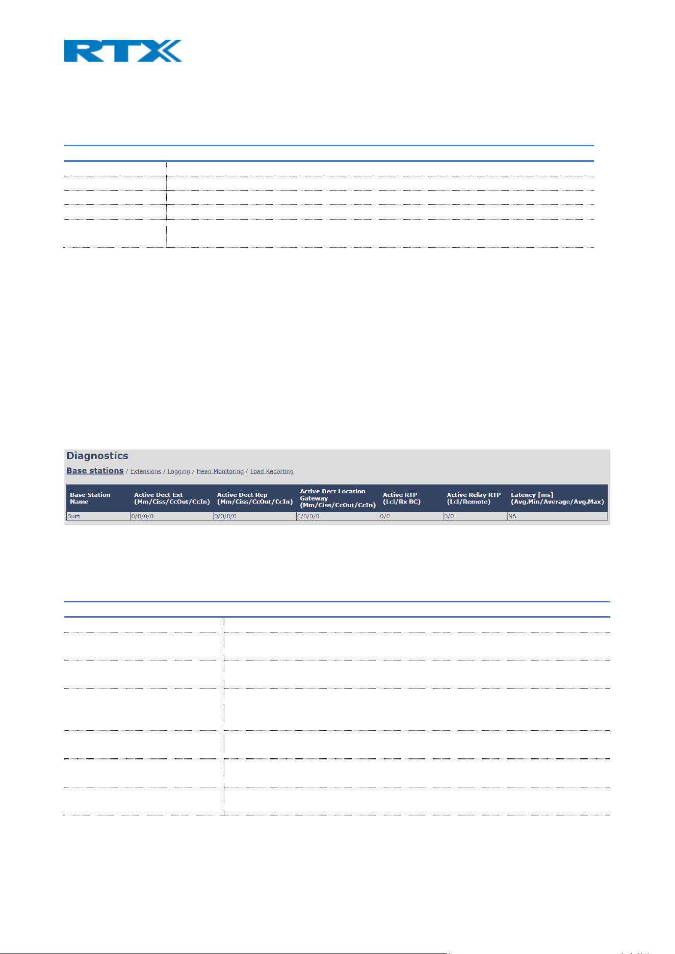
7.1.20.6 Heap Statistics
The table below describes the available parameters under this category:
PARAMETERS DESCRIPTION
HEAP SIZE Size of the heap memory in Bytes
HEAP USED The current use of heap in Bytes.
HEAP FREE Number of free Bytes.
HEAP FREE (%) Free heap memory in %.
LARGEST FREE
BLOCK
Size of largest free block in Bytes.
7.1.21 Diagnostics
This menu provides information about the Ethernet connection to each base station and extension (Fig.44).
It includes the following five administrative pages, which are described accordingly.
1. Base stations
2. Extensions
3. Logging
4. Heap Monitoring
5. Load Reporting
Figure 46 Diagnostics.
7.1.21.1 Base stations
The table below describes the available parameters on this page.
PARAMETERS DESCRIPTION
BASE STATION NAME Base IP address and base name (name can be edited in the Management page)
ACTIVE DECT EXT
(MM/CISS/CCOUT/CCIN)
Number of active DECT MAC connections to extensions on the different base
stations. Type of connection is mm/Ciss/CcOut/CcIn
ACTIVE DECT REP
(MM/CISS/CCOUT/CCIN)
Number of active DECT MAC connections to repeaters on the different base
stations. Type of connection is mm/Ciss/CcOut/CcIn
AACTIVE DECT LOCATION
GATEWAY
(MM/CISS/CCOUT/CCIN)
Number of active DECT MAC connections to location gateways on the different
base stations. Type of connection is mm/Ciss/CcOut/CcIn
ACTIVE RTP
(LCL/RX BC)
Number of active RTP Streams used. Types of streams are Local RTP
stream/Broadcast Receive RTP stream
ACTIVE RELAY RTP
(LCL/REMOTE)
Number of active RTP Relay Streams used. Types of streams are Local RTP Relay
stream/Remote RTP Relay stream
LATENCY [MS]
(AVG.MIN/AVERAGE/AVG.MAX)
Ping latency between base station performed by base index 0.
Average Minimum delay/Average/Average Maximum delay)

7.1.21.2 Extensions
Information on this page is visible only if there is a handset crash. The table below describes the available
parameters.
PARAMETERS DESCRIPTION
IDX Extension index number
NO OF HS RESTARTS Displays the number of times the handset has restarted
LAST HS RESTART
(DD/MM/YYYY
HH:MM:SS)
Displays the date and time of the last handset restart
7.1.21.3 Logging
The system includes monitoring features such as PCAP capture and syslog logging. Admins may detect
anomalies like repeated failed logins, malformed packets, or unexpected service activity. Broadcast and
multicast packets can be traced to assess potential denial-of-service vectors.
This page allows the administrator to collect system diagnostics information into a zip file. The zip file includes
all type of information, such as RSX trace, Syslog, SIP Log, Config file(s), etc.
There are two types of tracing which can be enabled – RSX and PCAP internal tracing. Administrators can
enable detailed trace logging of SIP signaling, configuration access, and system events. These logs help detect
configuration tampering, repeated access attempts, or malformed traffic. After configuring the type of traces
that need to be collected, the changes must be saved. Next, after collecting the data, the administrator can
choose from which base stations to download the traces. If it is a multi/dual cell system, the data can be
downloaded from all base stations in one file. Else, the system diagnostics can be downloaded from the
current machine. The available trace settings are described in the following sub-sections.
7.1.21.3.1 RSX internal tracing
RSX internal tracing can be either enabled or disabled. If enabled, the traced data should be sent to RTX,
since it can only be investigated by RTX engineers.
7.1.21.3.2 PCAP internal tracing
This feature allows the user to choose which trace to investigate by selecting the desired parameter.
PARAMETERS DESCRIPTION
TRACE PACKETS
TO/FROM THIS BASE
(EXCEPT AUDIO)
If selected, all Ethernet packets sent to/from the base station’s MAC address will be
traced. Broadcast packets sent from the base are also being traced.
TRACE AUDIO PACKETS
TO/FROM THIS BASE
If selected, RTP streams to/from the base station will be traced. Audio packets are
filtered by the port number used for RTP packets (configured on the Network page)
TRACE RECEIVED
BROADCAST PACKETS
If selected, all broadcast packets, received by the base station, will be traced.
TRACE RECEIVED IPV4
MULTICAST PACKETS
If selected, all received IPv4 multicast packets will be traced
TRACE RECEIVED
PACKET WITH
DESTINATION MAC
BETWEEN
If selected, each byte of the received destination MAC is checked to verify if it is in the
trace range
TRACE RECEIVED
ETHERTYPE
If selected, the user can select up to 3 received Ethertypes to trace

TRACE RECEIVED IPV4
PROTOCOL
If selected, the user can select up to 3 received IPv4 protocols to trace
TRACE RECEIVED
TCP/UDP PORT
If selected, the user can select up to 3 received TCP/UDP ports to trace.
7.1.21.4 Heap Monitoring
This feature allows the user to define the values of heap usage parameters that will be tracked in syslog
and under Generic Statistics page.
PARAMETERS DESCRIPTION
HEAP STATISTICS Default value 60 sec. Defines the distance between data points in usage curves.
HEAP USAGE IN SYSLOG Default value 60 sec. Defines how often is heap usage written to syslog.
HEAP ANALYSIS Time window: Default value 30 min. Blocks older than defined time window will be
ignored when running the analysis.
Analysis in syslog. Interval: Default value 0 min. Defines how often is heap analysis
logged to the syslog.
Result:
NOTE: This feature is disabled by default to save energy and alleviate performance. User can enable it as
needed but should have in mind that it uses resources and therefore will slow down the performance of the
base station.
7.1.21.5 Load Reporting
This feature allows to change the parameters that define the reporting of the system load of the base
station. Those results can be seen in the syslog.
PARAMETERS DESCRIPTION
ENABLE LOAD
REPORTING
Default value: Disabled.
When enabled allows to collect information about the system load of the base station.
SYNCRONIZATION OF
LOAD REPORTING
INTERVAL
Default value: Disabled.
This parameter controls if the sample interval shall be synchronized between all bases
in a multi cell setup, or if it applies only to the current base on which it is changed.
LOAD REPORTING
INTERVAL
Default value: 20 sec.
Defines the interval of time where data is sampled and presented in the syslog.
NOTE: This feature is disabled by default to save energy and alleviate performance. User can enable it as
needed but should have in mind that it uses resources and therefore will slow down the performance of the
base station.
7.1.22 Configuration
This page provides a non-editable information of the entire SME VoIP parameter settings (Fig.45). They
represent the “background” of the user-friendly interface. These settings can be exported, edited, and then
uploaded to the base again. The file handling, which contains these parameters, is called a configuration
(provisioning) file, whereas the settings application process is called provisioning.
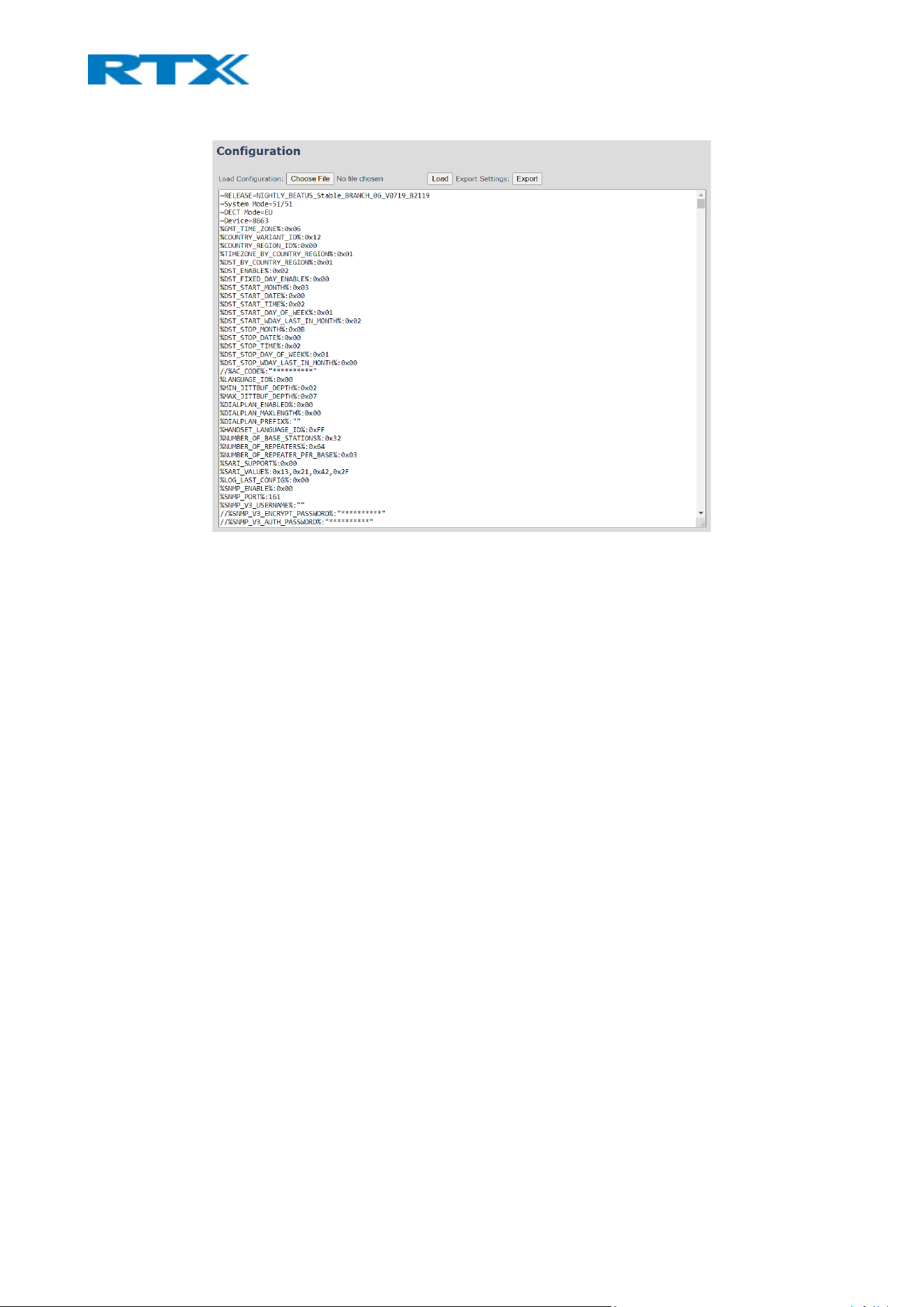
Figure 47 Configuration page
There are three ways to edit and apply the parameter settings.
• Using the SME VoIP Web interface – This method includes a manual configuration of the
base, by using the web interface. The parameters from the configuration file represent the
settings on every page. Therefore, if any setting is modified via the web interface, it will
also take effect on the parameters from the Configuration page (file).
• Using the Configuration page of the VoIP SME web interface (provisioning) – This method
includes a manual upload of the configuration file directly to the base. An example of using
this method is to export the configuration file and modify the relevant parameters.
Afterwards, save the changes and upload the file to the base station via the Configuration
page.
• Retrieving the relevant configuration file from the TFTP server (provisioning)– This
method includes a server on which the configuration file is stored and respectively
downloaded by the base. An example of using this configuration method is to export the
configuration file from the base station and rename it to the MAC address of the device
(<MAC_Address>.cfg). Then, modify the settings and save the configuration file in the
folder /Config on the TFTP server. Navigate the base to the server (via the Management
page). The base station will retrieve the file and apply the changes. Afterwards, any
changes made to the file on the server, will be applied to the base.
Supported formats for configuration files are .txt and .cfg.
NOTE: From v460 the base stations support configuration files up to 1MB
NOTE: Passwords/Credentials are not exported for security reasons.
For a detailed description on how to use provisioning, please refer to the Provisioning of SME VoIP System
(24).pdf guide.

7.1.23 Syslog
This page displays live feed of system level messages of the current base station (Fig.46). The displayed
messages depend on the configured settings on the Management page. The logs can either show only Boot
Log or All logs, meaning all system and boot logs. The Debug log is saved in the file format
<Time_Stamp>b.log in a relevant location on the TFTP server, as specified in the upload script.
Figure 48 Syslog page
There are four buttons available, allowing the administrator to:
• Clear – delete the current logs.
• Reload – refresh the logs
• Dump Crash Log – import the crash errors, if any, into the log. An example is an Unexpected Reboot
of the base
• Clear Crash log – delete the crash errors from the log
• Export – download the logs (syslog file)
7.1.24 SIP log
This page displays SIP server related messages that are logged during the operation of the SME system
(Fig.47). The SIP log is saved in the file format <MAC_Address><Time_Stamp>SIP.log on the relevant TFTP
server.
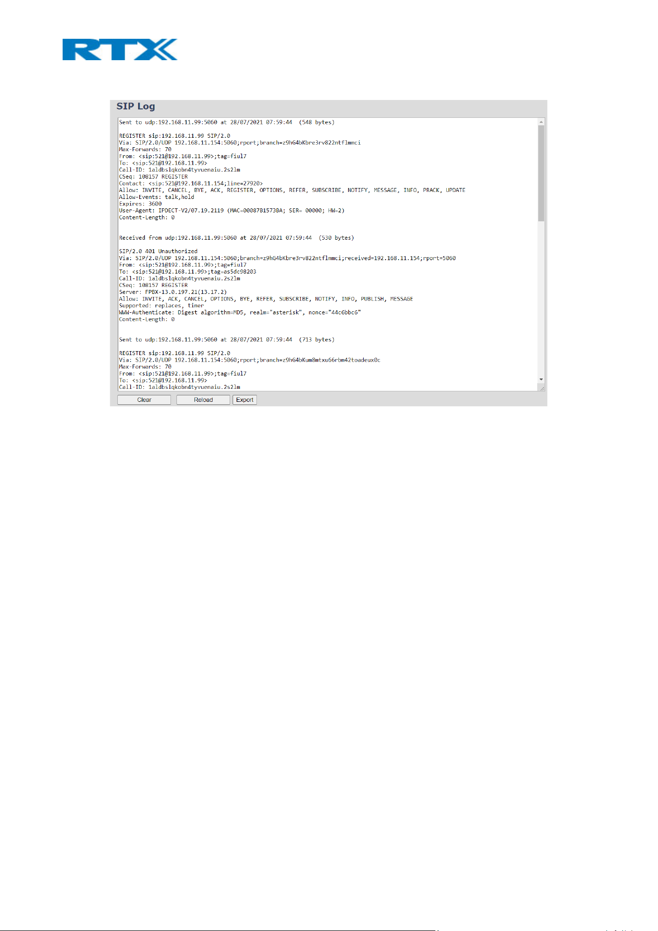
Figure 49 SIP log page
There are four buttons available, allowing the user to:
• Clear – delete the current logs.
• Reload – refresh the logs
• Export – download the logs (siplog file)
7.1.25 Emergency call
The base station allows the user to define emergency numbers, which can be dialed during key lock (Fig.48).
They have the highest priority during a call, meaning that if needed, the base will release non-emergency
calls to free resources to handle the emergency ones. However, in case the base is fully occupied with
emergency calls, then priority is given to the established calls and new incoming emergency calls are rejected.
If no numbers are configured on the base station, the handset can still dial national emergency numbers
(refer to 9.2.1 National emergency numbers). However, if any number has been configured, the national
emergency numbers become unavailable, unless they are also added to the configuration.
Further details on the ELIN and HELD support can be found in 9.3 ELIN and HELD support.
NOTE: When updating the setting on a multi/dual cell system, a reboot of the entire multi/dual cell or
handsets is required. It is needed for the handsets to receive the setting update and bypass any key-lock
/security functionality implemented on the device.
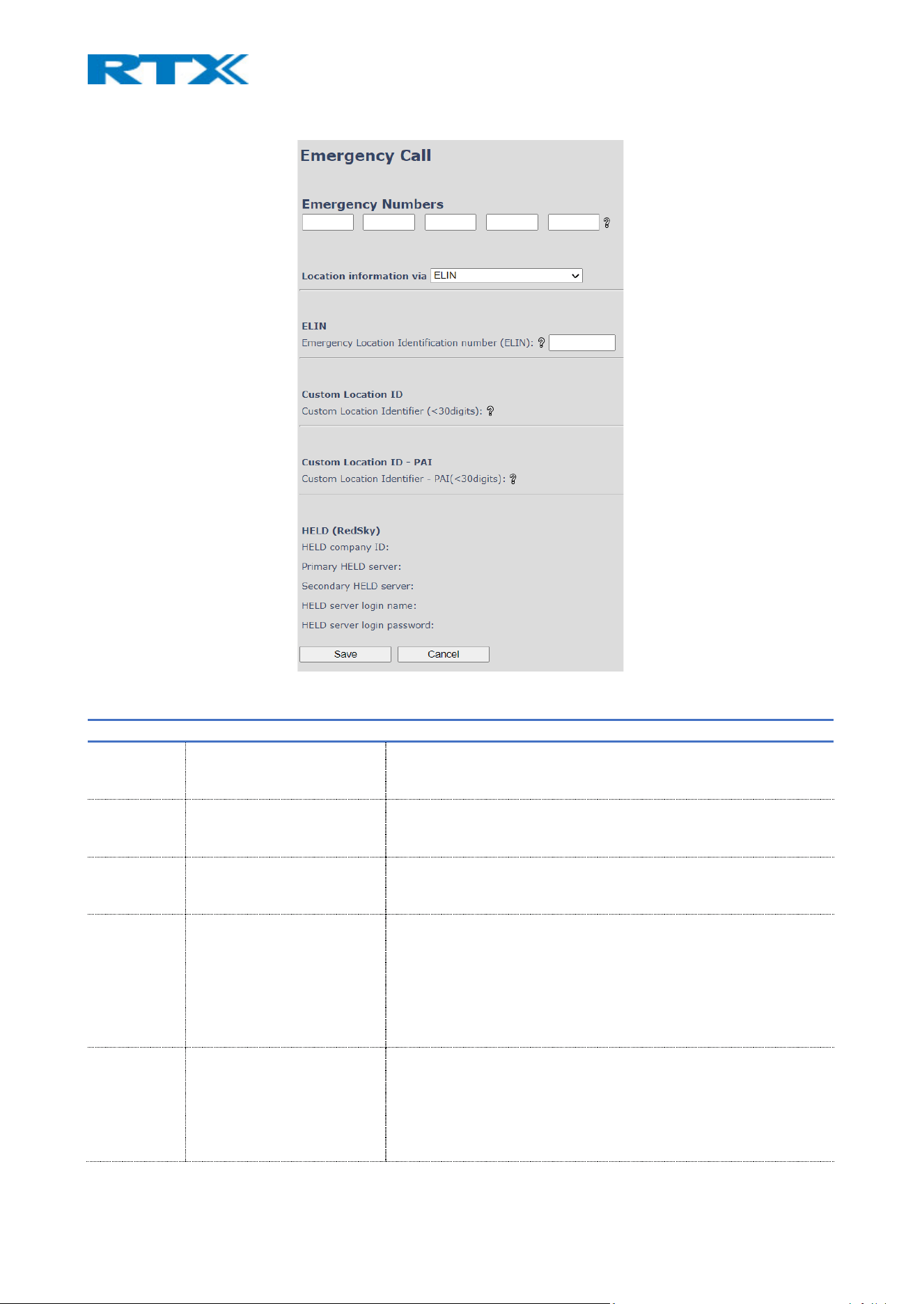
Figure 50 Emergency Call page
PARAMETER Default value Description
EMERGENCY
NUMBERS
Empty Configuration of the emergency numbers.
Permitted values: 0-9
Maximum digits: 7
LOCATION
INFORMATI
ON VIA
ELIN Select the desired method for providing location
Available options: ELIN/ Custom ID/ Custom ID-PAI/ HELD-RedSky
ELIN Empty Configuration of the unique ELIN number
Permitted values: 0-9
Maximum digits: 10
CUSTOM
LOCATION
ID
Empty Configuration of the Custom Location ID
Permitted values:
ABCDEFGHIJKLMNOPQRSTUVWXYZabcdefghijklmnopqrstuvwxyz012
34567890-.!%*_+~
Maximum characters: 29
NOTE: No spaces are allowed as part of the string
CUSTOM
LOCATION
ID PAI
Empty Configuration of the Custom Location ID-PAI
Permitted values:
ABCDEFGHIJKLMNOPQRSTUVWXYZabcdefghijklmnopqrstuvwxyz012
34567890-.!%*_+~
Maximum characters: 29

NOTE: No spaces are allowed as part of the string
HELD
COMPANY
ID
Empty The HELD Company ID is the account in RedSky which the
administrator’s company obtains.
Maximum length: 48
PRIMARY
HELD
SERVER
https://primelab.e911cloud.
com/
Configuration of the Primary HELD Server
Maximum length: 69
SECONDARY
HELD
SERVER
https://primelab.e911cloud.
com/
Configuration of the Secondary HELD Server
Maximum length: 69
NOTE: This setting is optional. However, it is advisable to have it
present, in case a server exists.
HELD
SERVER
LOGIN
NAME
Empty Configuration of the HELD Server Login name
Maximum length: 19
NOTE: Currently, login credentials are not mandatory. However,
they may become if RedSky’s authentication requirements change
HELD
SERVER
LOGIN
PASSWORD
Empty Configuration of the HELD Server Login password
Maximum length: 49
NOTE: Currently, login credentials are not mandatory. However,
they may become if RedSky’s authentication requirements change
7.1.26 Logout
This feature allows the user to log out from the system.
7.1.27 Notification of Privacy-Affecting Changes
This section explains how the system informs users or administrators when changes occur that impact data
protection or handling behavior.
Notification Events
The system issues notifications when any of the following take place:
• Enabling or modifying system logging features
• Firmware updates that introduce new data flows or communication behavior
• Updates to access credentials, certificates, or phonebook synchronization
Notification Delivery and Acknowledgment
Notifications are delivered through the following mechanisms:
• On-screen prompts displayed on handsets or the web configuration interface
• Alerts shown in the companion application (if connected)
• Status LED indicators paired with on-screen messages
• Log entries accessible to administrators (e.g., Syslog, SIP log)
Interactive notifications must be explicitly acknowledged. Passive notices are considered accepted upon
continued use of the system. All notification events are logged for traceability (see section 7.1.7.7).
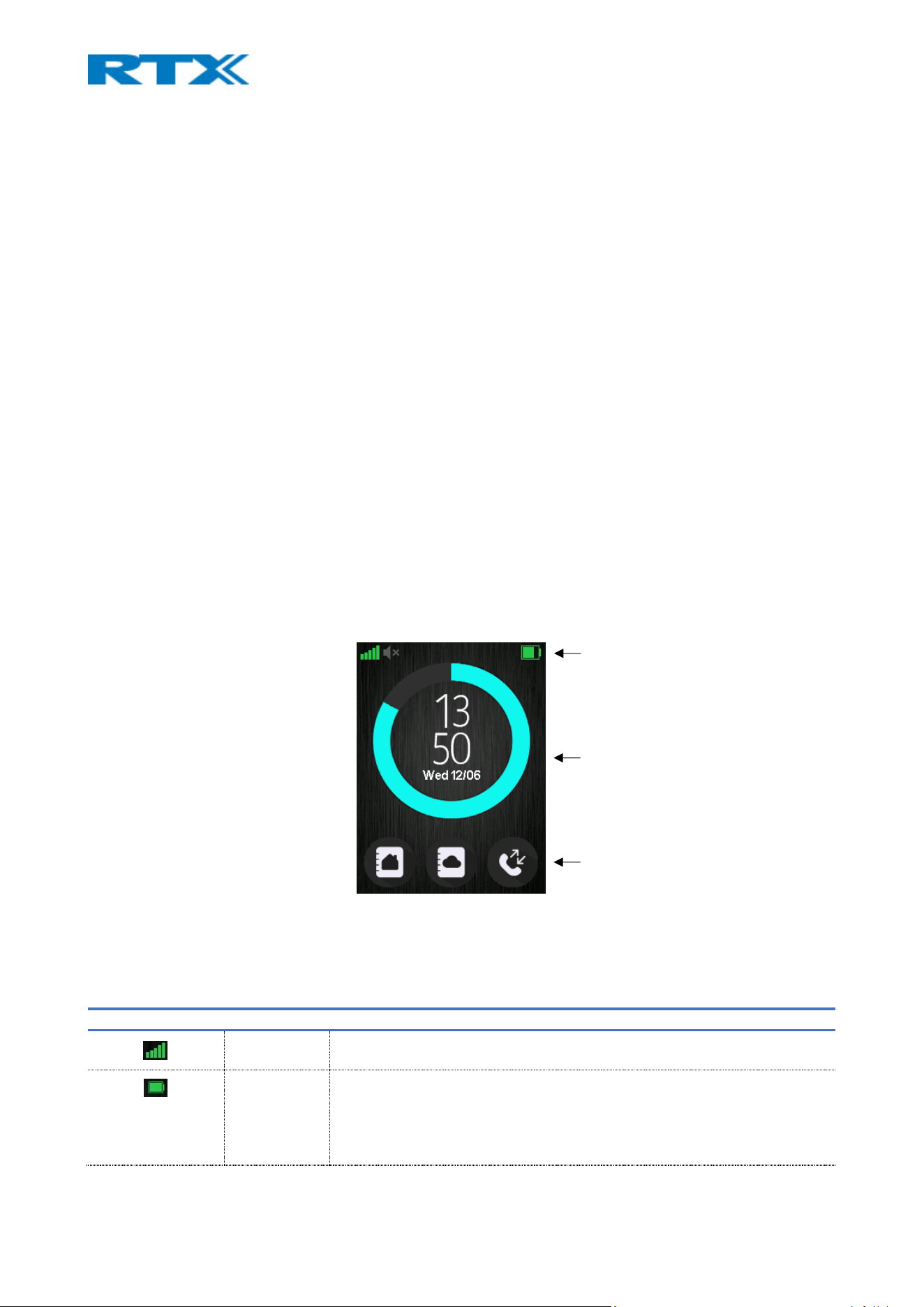
7.2 Handsets
All available functions and settings are displayed as icons and text on the handset screen. Even though there
are 2 types of user interfaces (Classic and Modern), the icons are similar and the functionality is the same
(refer to 2.3.2 Handsets for more details).
7.2.1 General overview
The screenshot below (Fig.49) illustrates a Modern user interface of an RTX8631 handset. This interface is
used in throughout chapter to identify the available icons, menus and symbols present in each of RTX’s
handset devices. Any visible difference in the layout between the various handset models, is additionally
mentioned via a note.
The idle screen represents the standard layout of a handset, which consists of a Softkey bar, an Active area
and a Status bar. The bottom of the screen is referred to as the Softkey bar, which provides you both with
fast access to some menus (Contacts, Central Directory and Calls) and possibility to select various functions
(Select, View, More, etc.).
The middle part of the screen is referred to as the Active area of the display. Apart from displaying the time
and date to the user (in idle), it provides the view to all menus, functions, and pop-up dialog text boxes (such
as alarms, missed calls, etc.).
NOTE: The Classic interface can also display the following in idle: extension name, which can be set on the
web interface of the base station; the registration number; and the handset name, which can be set locally
on the handset.
The top of the display, which is visible on all screens (independent on the menus), is referred to as the Status
bar. The icons listed below can be visible on the Status bar and provide different information to the user.
ICON TYPE DESCRIPTION
Signal
strength
Always visible in the upper left corner. The number of green staples is
displayed according to the strength of the signal.
Battery Always visible in the upper right corner. The icon displays the battery status.
00 - 20% empty battery symbol
21 - 32% red battery symbol
33 - 44% yellow battery symbol
Status bar
Active area
Softkey bar
Figure 50 General UI overview
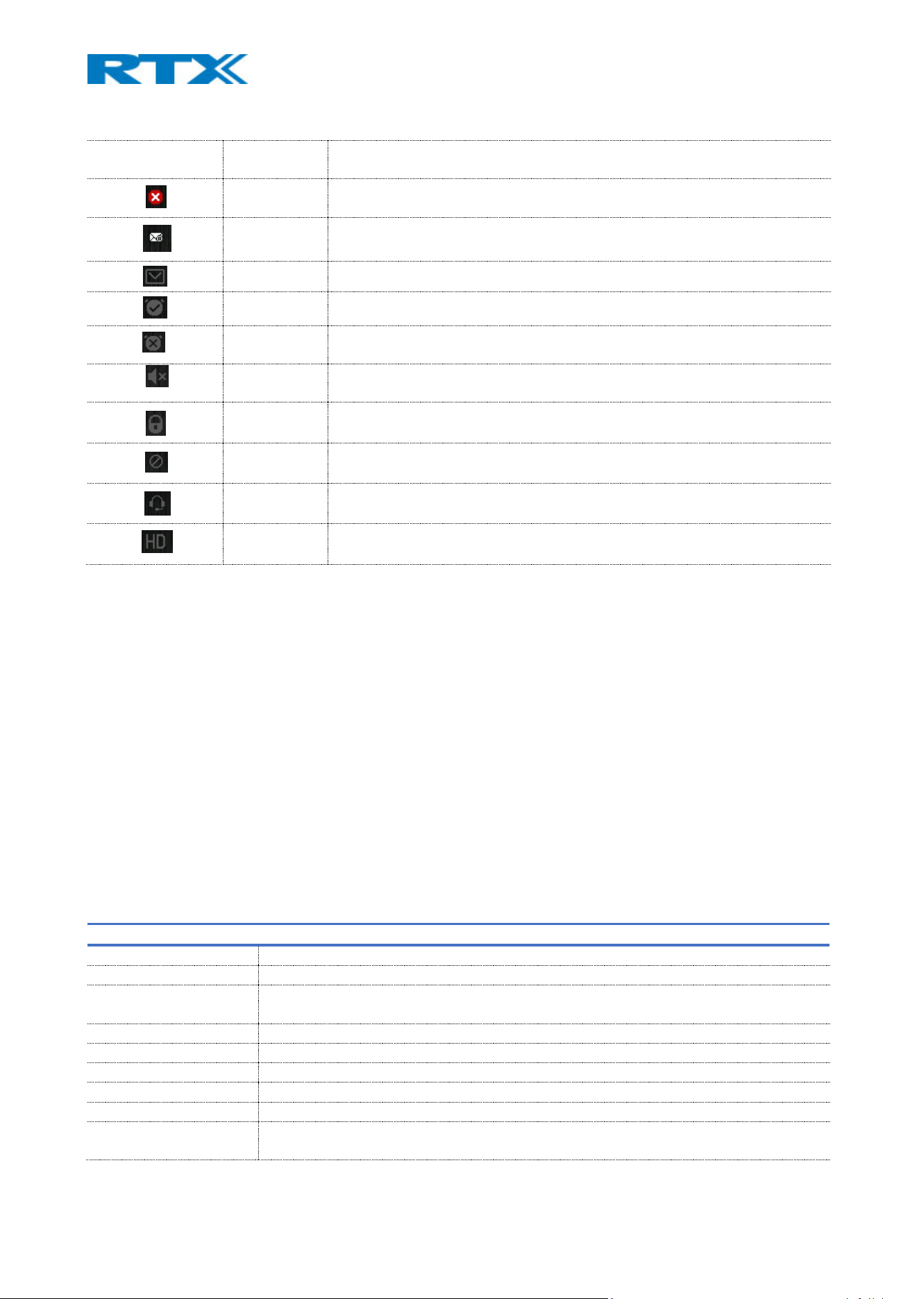
45 - 68% partly green battery symbol
69 - 100% full green battery symbol
Missed call Indicates that there has been a missed call. The call can be seen in the Call
log menu.
Voice mail
message
Indicates that there are voice mails that have not been listened to. This icon
remains visible until the voice mail has been opened.
Message Indicates that there are messages on the handset that have not been read.
Alarm clock Indicates that an alarm clock has been set on the handset.
Silent Alarm
clock
This icon is visible when an alarm clock is enabled and the handset is either in
silent mode, or the volume is muted
Sound
off/Silent
Indicates that silent mode is enabled on the handset
Keylock Indicates when the keypad is locked. To unlock it, the user needs to
longpress the * -key to be able to use the handset again.
Do not
disturb
Indicates that the feature “Do not disturb” is enabled. In this case, the
handset does not react to any incoming calls.
Headset
attached
Indicates that a wired headset has been inserted and detected
High
Definition
This icon is displayed during a call and indicates if the call quality is High
definition and thus, using the 722 codec
7.2.2 Call Screen
To make a call from Idle simply enter the phone number from the keypad and press the off-hook key.
To answer a call simply press the hook-off key.
When the handset is in a call it shows on the screen the number we are connected to. In some models it
shows in the top right corner the line we are using to connect to that call (that is in the case of having
multiple lines used on a single device. To see how to setup a multiline look at section 8.3.1.1). There can
also be present (depending on the model of the handset) small icons showing incoming call, outgoing call
and if the call is currently on hold.
7.3 Menu navigation
All menus on the handset can be accessed by pressing the Menu key on the device. During navigation, the
highlighted icon is moving to indicate the user where the navigation key is. The table below provides further
information about the different menus available on the handsets.
MENU DESCRIPTION
CONTACTS Contains all names/numbers in the local phonebook.
CALLS Contains the call log and provides information about the calls
CONNECTIVITY Contains network options, including registering/deregistering a handset to/from the
base.
SETTINGS Contains handset settings such as time/date, language, handset name, etc.
MESSAGING Contains sent and received messages, along with the available messaging settings.
ALARMS Contains alarm clock settings
F-KEYS Contains personal handset settings for the F-Keys
ALARM LIST Contains alarms received on the handset.
CENTRAL DIRECTORY Contains all names/numbers in the central directory of the system. The central directory
can be set up on the base (refer to 7.1.13 Central Directory for more information)
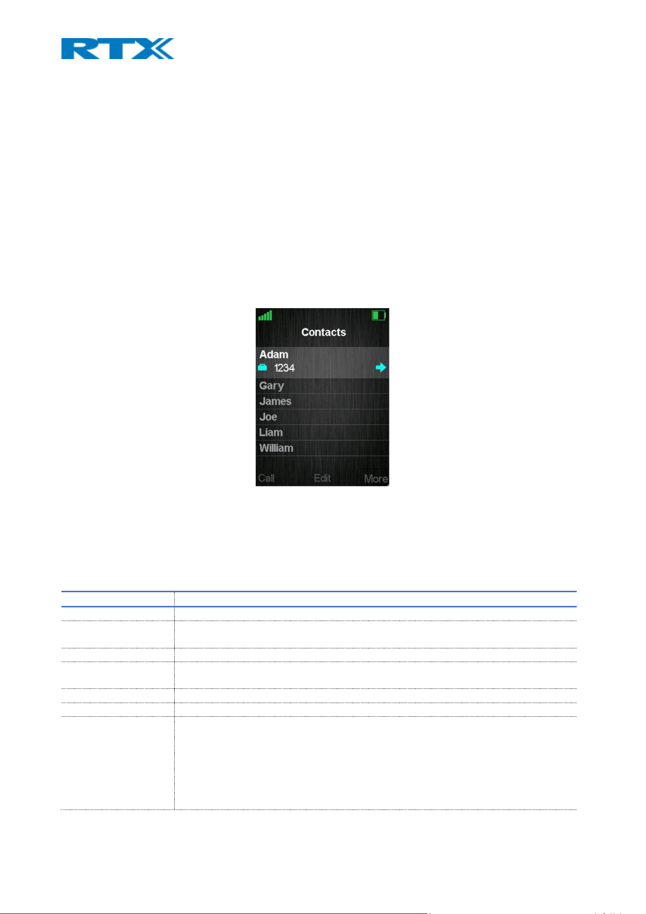
Some of the menus can also be accessed via the three softkeys in idle (Fig.49). These are the Contacts menu
(left softkey), the Central Directory menu (middle softkey) and the Calls menu (right softkey). These fast
access menus are pre-fixed and cannot be changed.
The following subsections will introduce each menu of the handset and its available options.
7.3.1 Contacts
This menu displays the available local contacts on the handset (Fig.50). If the contact list has entries, there
will be three available options assigned to the softkeys – Call (to call the selected contact), Edit (to edit the
selected contact) and More (other available options, further described in the following table). If the contact
has more than one number available (work, home, mobile, etc.) a small arrow appears to the right of the
contact. Pressing the navigation key to the right lets us toggle between the different numbers.
Figure 51 Contacts menu overview
When Central Directory is enabled, the user is presented with additional menu where they can choose
between Contacts and Central Directory. Upon choosing Contacts handset will access the Contacts list. If User
chooses Central Directory; handset will access the central directory contacts list.(refer to 7.3.9 Central
Directory for more details).
PARAMETER DESCRIPTION
SEND MESSAGE Provides the possibility to send a text message to the selected contact
ADD CONTACT Provides the possibility to create a new contact in the list by adding the name,
work/mobile/home/ other number of the contact and assigning a specific ringtone.
EDIT BEFORE CALL Provides the possibility to edit the contact’s number before calling it
EDIT CONTACT Provides the possibility to edit the contact’s information, such as name, number or
ringtone.
DELETE CONTACT Provides the possibility to delete the selected contact
DELETE ALL CONTACTS Provides the possibility to delete all contacts from the list
SPEED DIAL The feature allows the user to add a contact to a speed dial number (2 – 9). This enables
the user to directly call a contact from idle, by long pressing the key (2-9) to which the
contact is assigned to.
A contact can only be assigned to one speed dial number at a time. The first defined
number for the contact will be dialed when the speed dial key is pressed. This means
that if all numbers (work, mobile, home, and other) are defined for the contact, then the
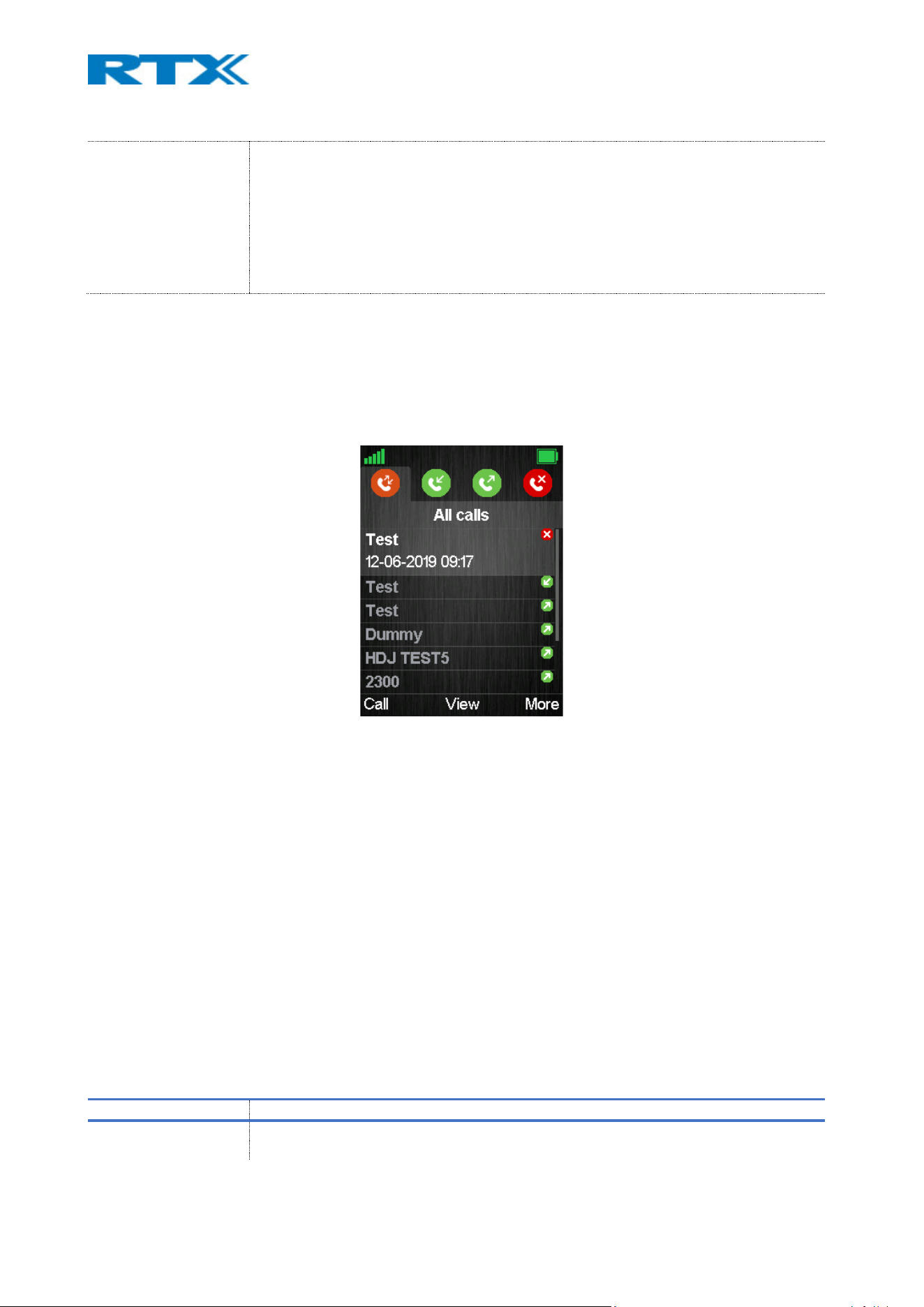
work number will be dialed first. If the work number is not defined, then the mobile
number is dialed, and etc.
NOTE: The ‘1’ key is reserved for voicemail. Long key press on ‘0’ is used for starting a
normal dial string with ‘+’.
NOTE: The speed dial list stores both contacts from the Contact and F-Keys list
NOTE: RTX8431/RTX8436 has 4 extra keys (F1,F2,F3 and F4) to which a contact can be
assigned as a speed dial key
NOTE: Both ASCII and Unicode are supported in the phonebook.
7.3.2 Calls
This is one of the menus that can be accessed via multiple ways – (1) the main menu, (2) the right softkey in
idle and (3) the green off-hook button from the keypad (Fig.51).
Figure 52 Calls menu overview
The menu provides lists of all the calls that have been made to and from the handset. The lists are organized
in tabs, which can be accessed by using the left/right navigation keys, and include the following:
• All calls – This list contains all the different types of calls (including both outgoing and incoming).
• Answered calls – This list contains all the incoming calls that have been answered.
• Dialed calls – This list contains all the calls that have been dialed from the handset.
• Missed calls – This list contains all the incoming calls that have not been answered.
NOTE: When there is a missed call on the handset, a red icon will be displayed in the status bar until the entry
has been viewed in the missed call list.
NOTE: The RTX8431 and RTX8436 do not support the tab-menu feature. All calls are listed in one menu
In every list, there are three available options assigned to the softkeys – Call (to call the highlighted entry),
View (displays call details of the highlighted entry) and More (other available options, further described in
the following table).
PARAMETER DESCRIPTION
VIEW DETAILS Displays call details, such as number, line, status (answered, missed, dialed), duration
and time stamp. It has the same output as the middle softkey option “View”
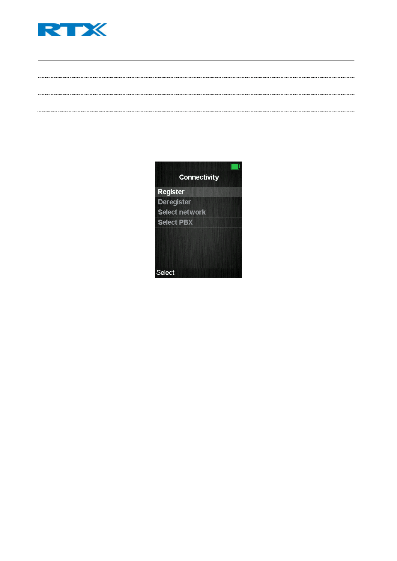
SAVE AS CONTACT Provides the possibility to save the number as a contact
APPEND TO CONTACT Provides the possibility to add the number to an existing contact
SEND MESSAGE Provides the possibility to send a message to the highlighted entry
EDIT BEFORE CALL Provides the possibility to edit the number before calling it
DELETE ITEM Provides the possibility to delete the highlighted entry
DELETE ALL ITEMS Provides the possibility to delete all entries from the specific call list
7.3.3 Connectivity
This menu allows the user to register/deregister a handset to/from a certain base system (Fig.52). The
following sections represent the available features and their related options.
Figure 53 Connectivity menu overview
7.3.3.1 Register
This feature allows the user to register a handset to a base station (VoIP system). Depending on the type of
handset, the device can register up to 10 different systems that are out of range from each other. To register
the handset, the user must select an empty slot and type in an access code (base registration PIN). By default,
the access code is “0000” and can only be changed via the base station (refer to 7.1.3 Extensions for more
information).
It is also possible to overwrite an existing registration by selecting the desired entry, instead of using an
empty slot.
NOTE: For the handset to function on different base systems, the device must be completely out of range of
system 1 to connect to system 2.
NOTE: RTX8431/RTX8436 can only register to 1 VoIP system.
7.3.3.2 Deregister
This option allows the user to deregister the handset from a base station (VoIP system). To deregister the
device, a PIN code (base deregistration PIN) must be typed by the user. By default, the code is “0000” and
can be changed via the handset (refer to 7.3.4.6 Security for more information). Afterwards, the registration,
which should be removed, must be selected and confirmed.
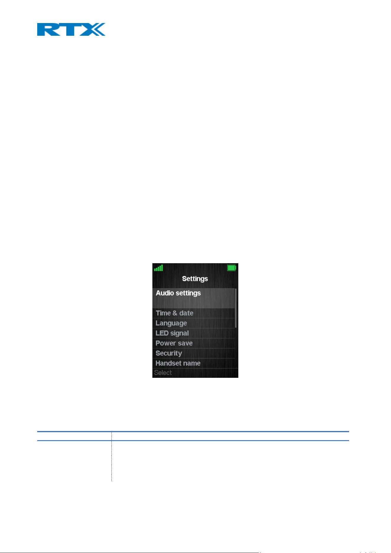
7.3.3.3 Select Network
If the handset is registered to different VoIP base systems (networks), this menu allows the user to select the
preferred network. In addition to this, it allows them to configure the handset to automatically select a
network. By doing so, the device will automatically choose a network in range.
NOTE: This feature is not available for RTX8431/RTX8436 handset
7.3.3.4 Select PBX
This menu provides the user with the possibility to select another PBX, which is to be used by the handset.
This means that, the handset can be connected to a different PBX than the one used by the base station
system. Hence, the handset can function on a PBX without being connected to a system of base stations.
7.3.3.5 Easy registration
This feature enables the user to add new handsets/repeaters without having to open the base webpage. This
means, that the user can physically enable the registration mode by pressing the reset button on the base
station, or by using the “Easy registration” menu on the handset. For further information on how to use the
feature, please refer to 8.3.4 Easy registration.
NOTE: This feature is only available for RTX8431/RTX8436 handset
7.3.4 Settings
This menu allows the user to configure various types of handset settings (Fig.53). The following sections
present the sub-menus along with the related features.
Figure 54 Settings menu overview
7.3.4.1 Audio settings
This sub-menu contains different settings related to the audio/sounds on the handset. The table below
displays the available features and their configuration possibilities.
PARAMETER DESCRIPTION
SILENT Enable/Disable silent mode on the handset
If enabled:
- Only melodies for emergency alarm messages will be played on the
device. Other sounds will be muted.

- Only the following sub-menus can be accessed: “Ring emerg. high /
med / low”, Vibrator” and “Noise reduction”
- The “Sound off” icon will be displayed on the status bar.
RING VOLUME Select the desired ring volume level for calls/messages on the handset. The currently
applied ring melody is played when adjusting the ring volume, thus the volume level
can be heard before being selected. The volume can be adjusted from mute (no
sound) to level 6 (highest sound).
NOTE: If the volume is set to mute, no melodies will be played when receiving an
incoming call or message. The “Sound off” icon will be displayed on the status bar.
RING MELODY Contains a list of melodies from which the user can browse through. The chosen
melody will be played during an incoming call.
The melodies can be heard before being selected.
RING NORMAL MSG Contains a list of melodies from which the user can browse through. The chosen
melody will be played when messages, prioritized as normal, are received on the
handset.
NOTE: The message ring melodies are played with the same ring volume as the setup
for incoming calls.
RING URGENT MSG Contains a list of melodies from which the user can browse through. The chosen
melody will be played when messages, prioritized as urgent, are received on the
handset.
NOTE: The message ring melodies are played with the same ring volume as the setup
for incoming calls.
RING EMERGENCY HIGH
/MED
/LOW
Contains a list of melodies from which the user can browse through. The chosen
melody will be played when alarm messages are received on the handset. Depending
on the priority of the alarm (high/med/low), a different melody can be selected
ALERT VOLUME Select the desired ring volume level for the alarm clock. The currently applied ring
melody is played when adjusting the ring volume, thus the volume level can be heard
before being selected. The volume can be adjusted from mute (no sound) to level 6
(highest sound).
NOTE: If the volume is set to mute, no melody will be played when the alarm occurs.
NOTE: If an alarm clock is configured and the volume level is set to mute, a “Sound off
alarm clock” icon will be displayed on the status bar.
ALERT TONE Contains a list of melodies from which the user can browse through. The chosen
melody will be played when an alarm clock ring occurs.
The melodies can be heard before being selected.
VIBRATOR Provides different vibrator options for the handset:
Off: Vibrator is disabled. The handset will not vibrate during alerts (calls/messages)
Vibrate then ring: When an alert occurs (call/message), the handset will vibrate 4
times. Afterwards, the vibration will stop, and the handset will ring instead.
Vibrate only: The handset will vibrate only, without ringing (even if the ringing signal
is enabled on a certain level)
Vibrate and ring: The handset will both vibrate and ring at the same time, when an
alert occurs (call/message)
KEY SOUND Controls if a sound is played when keys are pressed on the handset. The following
options are available:
Silent: No key sound will be played
Click: A “click” key sound will be played

Tone: A “tone” key sound will be played
NOTE: Even if one of the options (Click/Tone) is enabled, no key sound will be
generated when pressing the keys during “key lock state”
CONFIRMATION SOUND Enable/Disable confirmation sounds on the handset
If enabled, an audible indication is given when an event succeeds or fails. For
example, a positive confirmation sound is generated when a new setting is set, or an
entry is saved successfully in the phonebook. A negative confirmation sound is
generated if the action fails
COVERAGE WARNING Enable/Disable a coverage warning sound to occur when the handset is out of range
of a base station in the system.
If enabled, an audible indication is given in the earpiece of the handset when the user
is close to the maximum range of the nearest base station in the system. Thus, the
user knows that the call is at the edge of the possible coverage and must move back
in coverage to keep the call active.
NOTE: This feature is only working when the handset is in call. Not when in idle.
CHARGER WARNING Enable/Disable the handset to generate a sound, when put in the charger, to indicate
that the handset is charging.
SPEAKERPHONE
PROFILES
Customize the tonality of the speakerphone mode. The following profiles are
available:
Balanced: controls the pleasant tonality of the speech
Loud: prioritizes the loudness of the speech
NOTE: If the user selects “Balanced”, the sound quality will become more pleasant, but
also low.
NOTE: This feature is only supported by RTX8631-32-33
NOISE REDUCTION Enable/Disable noise reduction. It is a function used when the handset is in a call. An
algorithm is used to reduce the noise from the background. In this way, the user
should sound clearer to the counterpart since the noise is reduced to a certain level.
The following level options are available:
Low: The noise is reduced by approx. 6dB
High: The noise is reduced by approx. 12dB
NOTE: This feature is not supported by RTX8630 and RTX8830
NOISE CANCELING Enable/Disable noise canceling. It is a function used when the handset is in a call. This
feature is more advanced than Noise reduction, as it uses 2 microphone solutions to
reduce the background noise to a minimum.
NOTE: This feature is only supported by RTX8830
7.3.4.2 Time & date
This sub-menu allows the user to configure the time and date on the handset. The table below displays the
available features and their configuration possibilities.
PARAMETER DESCRIPTION
TIME Set the time and choose the desired format:
24h

12h (am/pm)
DATE Set the date and choose the desired format:
dd-mm-yyyy
mm/dd/yyyy and etc.
7.3.4.3 Language
This sub-menu lists the available languages to which the handset can be configured. The list can be seen in
the table below.
English Español Deutsch Français Italiano Nederlands
Português Dansk Svenska Turkçe Polski Norsk
Russian – 1 Russian – 2 Hrvatski Srpski Slovenian
7.3.4.4 LED signal
This sub-menu represents the configuration of the LED, located at the upper left corner of the handset. The
LED has 3 colors (green, yellow (purple), red), which can respectively be configured to indicate the user with
a certain event.
PARAMETER DESCRIPTION
GREEN /YELLOW (PURPLE)
/RED LED
For every color, select one of the following events which it should correspond to.
Off: The LED signal is disabled, and does not blink in any situation
Missed call: The LED signal blinks in the selected color when there is a missed call
Voice message: The LED signal blinks in the selected color when there is a voice mail
message that has not been listened to.
Low battery: The LED signal blinks in the selected color when the battery is low
(below 20% battery on the handset).
NOTE: The purple color is only available for RTX8830
7.3.4.5 Power save
This sub-menu allows the user to minimize the battery consumption by configuring the display to turn off
after a certain amount of time.
SECONDS 5s 10s 20s 30s 45s 60s
7.3.4.6 Security
This sub-menu provides the user with the possibility to configure and control the user’s access to the device
and its features. The table below illustrates the available options.
PARAMETER DESCRIPTION
PHONE LOCK Enable/Disable the possibility to lock the phone while in standby mode.
If enabled, a code must be entered to unlock the device. Use the * key to access the
code pop-up message.
Change PIN: Allows the user to change the PIN code of the phone lock.

NOTE: The default code is 0000
NOTE: To apply the saved settings, the handset needs to be rebooted.
AUTOMATIC KEYLOCK Enable/Disable this handset option to automatically lock the keypad after a certain
amount of time that the device has not been active. This means that the handset keys
cannot be used until the user unlocks the device (by long pressing *).
The following time intervals can be selected:
Off
15s / 30s / 45s
1 min / 2 min / 3 min / 4 min / 5 min
NOTE: Emergency numbers (e.g., 911 / 112) can be called without the need to unlock
the keypad
CHANGE PIN Change the handset’s security PIN code. The code is used when deregistering the
handset from the base and when resetting the handset’s settings.
NOTE: The current PIN code is 0000
NOTE: If an incorrect PIN is entered an option to reset the handset is available upon typing *73738*
(73738=RESET on the keys) A reset setting prompt is displayed, that allows user to reset the handsets
general settings. Be aware that, if performed, the reset will erase all the user data on the handset and the
handset will restart.
7.3.4.7 Alarm settings
This sub-menu allows the user to customize the following alarm settings:
PARAMETER DESCRIPTION
ALARM IN CALL ON/OFF
When enabled, and an alarm arrives during a call, it will
play the call waiting tone and show the alarm on the
screen.
If it is disabled, it will not play anything until the call is
over.
CALLBACK CONFIRM ON/OFF
When enabled, and alarm has been answered using a
call back option, a confirmation message will be sent to
the Alarm server, once the call has been established
with the specified callback number.
If disabled, no alarm confirmation message will be sent
to the alarm server.
NOTE: This confirmation functionality is currently not
compatible with voicemail options from the PBX, as this
connects the call and there currently is no way to
distinguish it from the call being answered on the
remote end.

7.3.4.8 Handset name
This sub-menu allows the user to edit the name of the handset.
HANDSET NAME Type in a name for the handset. The device’s name will be displayed on the third line of the
idle screen.
NOTE: If the Modern MMI is used, then the name will not be visible (this is not valid for the
modern interface of the B760 handset)
7.3.4.9 Line
This sub-menu allows the user to select the preferred line of the handset, if the device is registered to
multiple systems/SIP accounts.
LINE Select the desired line from the list.
7.3.4.10 Reset settings
This sub-menu provides the possibility to reset the handset’s settings to default.
RESET SETTINGS Reset the settings to default by typing in the PIN code (refer to 7.3.4.6 Security for more
details on the PIN code)
NOTE: After the reset, the handset is still registered to the base.
NOTE: When selecting this feature, the base is not reset to default
7.3.4.11 Status
This sub-menu provides useful information about the handset and the base station it is registered to.
STATUS The following information is displayed for the devices:
Base station status:
- Software version (the current software version of the base station)
- Hardware version (the hardware version of the base station)
- IP address (the IP address of the base station)
- MAC address (the MAC address of the base station)
- System name (the name of the system of base stations that the handset is registered to)
Handset status:
- Software version (the current software version of the handset)
- Hardware version (the hardware version of the handset)
- DECT band (the DECT band that the handset is using, e.g., EU or US)
- Battery level (the current battery level of the handset)
- IPEI (the IPEI/IPUI number of the handset is a static number identifying the specific
handset)
- Bluetooth (the Bluetooth MAC address of the handset)
NOTE: The Bluetooth MAC address is displayed only for devices supporting the Bluetooth
feature
7.3.4.12 Auto answer
This sub-menu allows the user to configure the handset to answer incoming calls in various ways.

AUTO ANSWER Select one of the below conditions to configure the desired mode
Normal: The user must manually answer the incoming calls by pressing the green “Off-
hook” button.
NOTE: The call is not answered by removing the handset from the charger.
Any Key: The user can press any key from the keypad to answer the incoming call.
NOTE: This does not include the red “On-hook” button and the three softkeys, which have
their different functions.
Automatic: Incoming calls are automatically answered after 5 seconds.
7.3.4.13 Silent charging
This sub-menu enables the handset to be configured to ring in silent mode while charging.
SILENT CHARGING Enable/Disable the handset to ring in silent mode while charging, by selecting one of the
options below:
Off: Audio alert is played during an incoming call
Silent: Incoming calls are received, but no audio is played
NOTE: The handset must be placed in the charger for this feature to work.
7.3.4.14 Do not disturb
This sub-menu allows the user to set up a “Do not disturb” mode, meaning that incoming calls will not be
received on the handset.
DO NOT DIRTURB Enable/Disable the incoming call activity.
If enabled, incoming calls will be rejected or redirected to a voicemail (if voicemail feature
is set). This means that, the base will not send any ringing indications. Else, it will be the
PBX that is sending the ringing before contacting the base.
NOTE: A “Do not disturb” icon will be displayed on the status bar if the feature is enabled
NOTE: If BroadSoft event feature package enabled the icon will not be showing. When
BroadSoft server is used, DND feature is controlled by the PBX and therefore, icon on the
idle screen won't show. In that case DND will appear as a text on idle screen instead.
7.3.4.15 Hide Number
This sub-menu provides the user with the opportunity to hide their number during an outgoing call. By
enabling this feature, the counterpart will not see the caller ID.
HIDE NUMBER Enable/Disable the device to hide its number by selecting one of the options below:
Off: The caller ID of the handset is displayed to the counterpart of the call
On for next call: The caller ID of the handset is hidden to the counterpart only for the next
outgoing call. Afterwards, the following calls will display the number.
Always on: The caller ID of the handset is always hidden to the counterpart for all outgoing
calls, until the feature is disabled again.

NOTE: When this feature is enabled, the base sends a SIP header “Privacy: id” to address
sip:anonymous@anonymous.invalid
NOTE: The PBX must support anonymous calls. Else, if the feature is enabled, the call will be
rejected. Thus, the handset will not be able to make an outgoing call.
7.3.4.16 Call forward
Depending on the scenario, this sub-menu enables the user to forward all incoming calls to a selected
number.
PARAMETER DESCRIPTION
FORWARD UNCONDITIONALLY Enable/Disable the possibility to forward all incoming calls to a pre-defined
number
Forward To: Type in the number to which the calls should be forwarded
NOTE: The handset will not receive any incoming calls, as all of them will be
directly forwarded to the provided number from above.
FORWARD NO ANSWER Enable/Disable the possibility to forward all incoming calls that are not
answered.
Forward To: Type in the number to which the calls should be forwarded
Forward After (s): Type in the timeframe which the user can makes use of to
answer the call. If this period ends and the call has not been answered, the call
will be forwarded to the provided number.
FORWARD BUSY Enable/Disable the possibility to forward all incoming calls while the handset is
busy (e.g., user is in another call) or when the user presses “Reject” on the call.
Forward To: Type in the number to which the calls should be forwarded
7.3.4.17 Idle screensaver
This sub-menu enables the handset to dim the light of the screen while in the charger.
IDLE SCREENSAVER Enable/Disable the screen light saving, while in the charger, by selecting one of the
following options:
Off: Feature is disabled. No lights will be dimmed while the handset is in the charger.
Idle clock (dimmed): The idle screen will dim the lights as soon as the handset enters
power save mode while in the charger.
Startup image (dimmed): The startup image will dim the lights as soon as the handset
enters power save mode while in the charger.
NOTE: If the feature is enabled, the handset screen will dim the light, but never turn off
7.3.4.18 Idle clock
This sub-menu allows the user to control the visibility of the clock on the idle screen.

IDLE CLOCK Enable/Disable the appearance of the clock on the idle screen
NOTE: A “Do not disturb” icon will be displayed on the status bar if the feature is enabled
NOTE: This feature is not supported by RTX8631 and RTX8632
7.3.4.19 Bluetooth
This sub-menu enables the handset to connect to a Bluetooth headset. When this connection is present, the
audio on all calls is routed through the Bluetooth headset. This means that, when receiving an incoming call,
alerting is heard both from the handset and the paired Bluetooth headset.
NOTE: This feature is not supported by RTX8431, RTX8436 and RTX8630
The following types of headsets are on the whitelist for RTX8830 Handset:
- Jabra Talk
- Jabra Stone
- Jabra Supreme
- Nokia BH-904
NOTE: The Jabra Supreme headset has two features - Jabra Voice Guidance and Jabra Voice Control. These
two features guide the user on how to use the headset and make it possible to control the hands-free by
using voice control. These Jabra Voice features are both supported by the RTX8830 handset.
The table below summarizes the available options in the Bluetooth sub-menu.
PARAMETER DESCRIPTION
ENABLE/DISABLE Enable/Disable the possibility to pair the handset to a Bluetooth headset.
NOTE: Pairing a handset to a Bluetooth device is possible only when Bluetooth
is enabled.
NOTE: When the feature is enabled, a Bluetooth icon is displayed on the status
bar of the handset. Depending on the paired mode, the icon appears in a
different style and color:
- Gray – if handset is not paired to another device
- Blue – if handset is paired to another device
SEARCH FOR DEVICES Select this option to search for other Bluetooth devices to which the handset
can connect. The detected devices (in pairing mode) will be listed by their IDs /
names on the handset display.
NOTE: Bluetooth must be enabled on the handset in order to search for other
Bluetooth devices. Else, as soon as a search is initiated, the Bluetooth feature
will automatically be enabled.
NOTE: The Bluetooth devices, that are to be found by the handset, need to be in
pairing mode.
NOTE: If a PIN code is requested when pairing the devices, it is usually 0000.
PAIRED DEVICES Provides a list with all paired devices. The handset can be paired with up to
four different Bluetooth headsets.

The user has the opportunity to Disconnect a Bluetooth device from the
handset or explore the following More options:
Change name: Allows the user to change the name of the paired Bluetooth
device
Delete: Allows the user to delete the selected paired device. If deleted, the
handset will no longer be paired with this device
Delete all: Allows the user to delete all paired devices. If deleted, the handset
will no longer be paired with any of these devices.
Info: Provides details about the paired device, such as Status, Headset Name
and Address.
7.3.4.20 Push To Talk
This sub-menu enables the handset to behave like a Walkie Talkie. This is done by pressing and holding the
mute button on the left side of the handset when in Idle state. As long as the mute button is pressed, it is
possible to talk to the other devices on the system that have the Push To Talk feature enabled. The received
voice is heard via the loudspeaker of the handset. To end the transmitting mode and allow the counterpart
to talk, the mute button must be released.
NOTE: This feature is not supported by RTX8431/RTX8436 handset
IMPORTANT: When enabled, this feature uses 2 channels to allow communication between the devices.
Therefore, even if the feature is enabled only on one device, the system has already reserved 2 channels for
the Push To Talk feature. This means that, instead of having the opportunity to establish 10 simultaneous
calls, the base system will be limited to 8 (see 2.3.1 Base stations for more info on the call capacity). In this
way, it is possible to have both 8 simultaneous calls and Push To Talk communication in the DECT
environment.
PUSH TO TALK Enable/Disable the “Walkie Talkie” function
NOTE: The feature must be enabled on at least two handsets in order for it work.
NOTE: Only one person at a time can talk on the Push To Talk system.
NOTE: Pressing and holding the mute button, while another user is talking, will only mute
the loudspeaker.
7.3.4.21 Function keys
As previously mentioned, the RTX8431/RTX8436 has 4 extra keys below the original keypad, referred to as
Function key X (F1, F2, F3 and F4) from left to the right-hand side. They can be configured by the user to
execute a certain action when being pressed. Selecting an action type for a function key can be done by the
following ways:
- Pressing a function key where no action has been assigned yet
- Navigating to the Function keys menu item.
NOTE: A function key will only perform its programmed action in idle state
NOTE: By default, no action is configured on the function keys
NOTE: This feature is only supported by RTX8431/RTX8436 handset
The table below summarizes the list of programmable options in the Function keys sub-menu.

PARAMETER DESCRIPTION
IGNORE KEY PRESS Enable/Disable the key press event
If enabled, any type of key press on the selected function key will be ignored
SPEED DIAL Allows the user to assign a contact from the local Contacts or F-Keys list to a function key.
The handset will call the assigned contact when the key is pressed.
The function keys are also visible in the Speed dial menu and can be found as F1, F2, F3 and
F4 (refer to 7.3.1 Contacts for more details)
NOTE: If a function key is assigned to a speed dial through the Speed dial menu, the
Function key menu will reflect the current function key state.
SHORTCUTS Opens a certain application, meaning that the handset will navigate to the specified
shortcut location and display the corresponding menu.
The following menus are supported as shortcuts:
- Send Message
- Inbox
- Sent Messages
- Settings
- Time and Date
- Audio settings
- Ringtone
- Ring Volume
- Status
- Connectivity
NOTE: Dismissing the shortcut will return to idle screen
Direct Call Lets the user set a number, that is called when the function key is pressed. The Direct Call
feature resembles a speed dial, however, while a speed dial requires a contact in the phone
book, the direct call is simply a number. One Direct Call number per function key can be
defined. To disable the Direct Call function ‘Ignore key press’ should be set to ‘On’. This will
not clear the number.
NOTE: This feature is not available for all handset models.
7.3.5 Messaging
This menu enables the user to send text messages to other handsets in the system and read the received
ones (Fig.54). It contains the following four sub-menus, which are organized in tabs and can be accessed by
using the left/right navigation keys:
• Inbox – Contains a list of all text messages that have been received on the handset
• Drafts – Enables new messages to be created and contains a list of unsent messages (drafts)
• Sent Messages – Contains a list of all text messages that have been sent from the handset
• Settings – Provides various message configuration options
The sub-menus and their related options are further described in the following sections.
NOTE: To enable the messaging feature, the base station must be configured accordingly (refer to 7.1.7.5
Text Messaging).
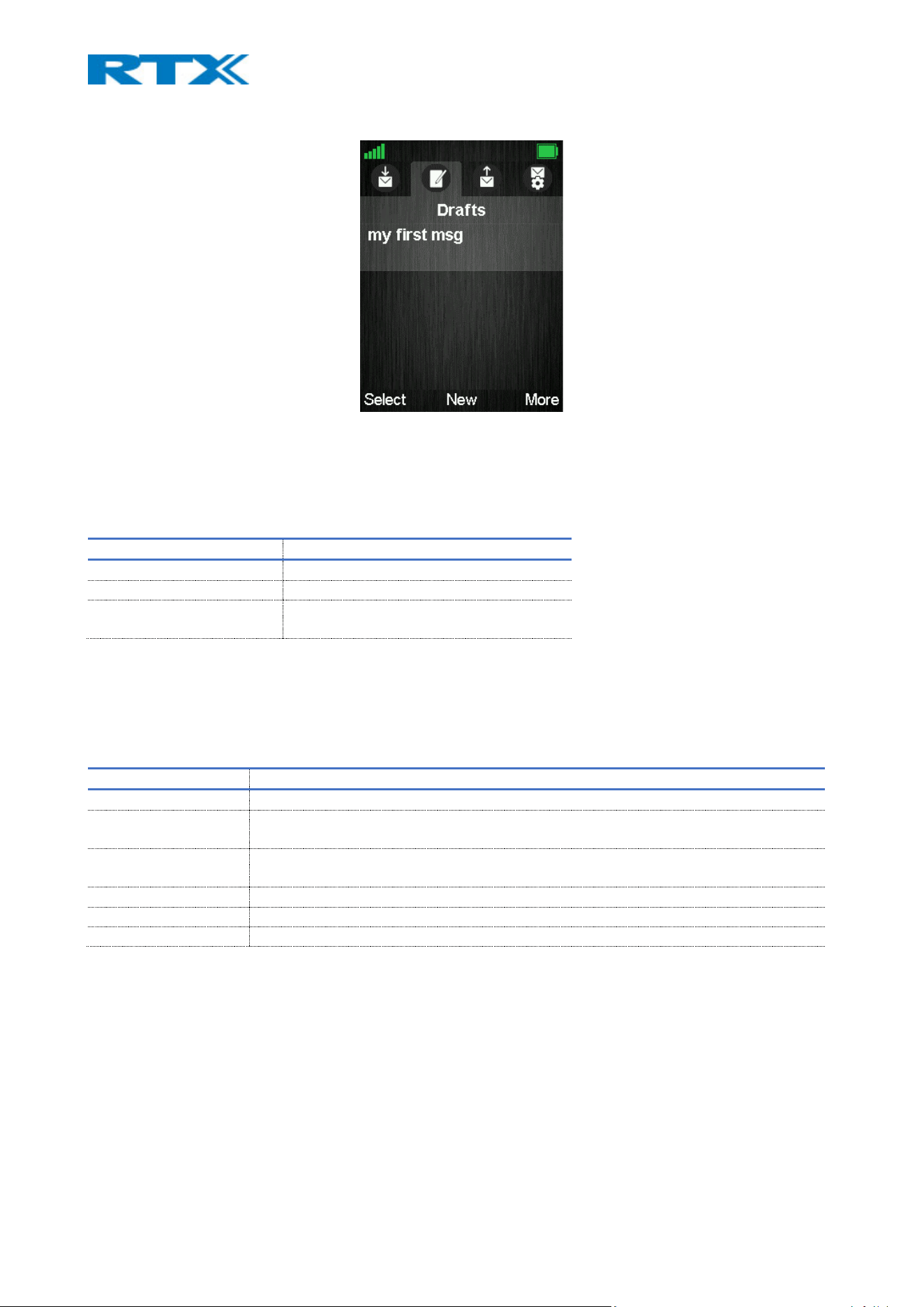
Figure 55 Messaging menu overview
Depending on the type of handset there is a difference in the amount of text messages that can be stored on
the device. The table below displays the maximum number of messages per handset. The number includes
both messages in Inbox, Drafts and Sent messages.
HANDSET TYPE MAXIMUM NUMBER OF TEXT MESSAGES
RTX8431/RTX8436 3
RTX8630 70
RTX8631/RTX8632/RTX8633
RTX8830
300
7.3.5.1 Inbox
This sub-menu stores and displays all the received text messages on the handset. When messages are
present, there are three available options assigned to the softkeys – Select (opens the highlighted message),
Reply (enables the user to reply to the highlighted message) and More (other available options, further
described in the following table).
PARAMETER DESCRIPTION
REPLY Provides the possibility to reply to the received message
FORWARD Provides the possibility to edit and forward (send) the message to another contact
(number)
SAVE AS CONTACT Provides the possibility to save the counterparts number, from whom the message was
received, to the local phonebook
APPEND TO CONTACT Provides the possibility to add the counterpart’s number to an existing contact
DELETE MESSAGE Provides the possibility to delete the highlighted message
DELETE ALL MESSAGES Provides the possibility to delete all messages from the Inbox
7.3.5.2 Drafts
This sub-menu enables the user to create a new text message and save it as a draft if the message is not sent.
Draft messages can be edited and sent to the counterpart. Therefore, this sub-menu provides both a list of
saved drafts and the opportunity to write a new message.
When messages are present in the list, there are three available options assigned to the softkeys – Select
(opens the highlighted message), New (enables the user to write a new message) and More (other available
options, further described in the following table). Else, only the middle softkey option New is visible to the
user.

PARAMETER DESCRIPTION
SEND MESSAGE Provides the possibility to send the written message.
DELETE MESSAGE Provides the possibility to delete the highlighted message
DELETE ALL MESSAGES Provides the possibility to delete all messages from the Drafts sub-menu
NOTE: When sending a message on some models, user is provided with the choice to either send it as a Normal
message or as an Urgent message. When sending an Urgent Message bear in mind that the handset receiving
the message will continue ringing (not just a short beep as with normal message) until the user takes action
and acknowledges or declines the message. If the handset receiving the message has silent mode enabled
there is no indication that the text message is urgent.
7.3.5.3 Sent messages
This sub-menu enables the user to review all the messages that have been sent from the handset. When
messages are present, there are three available options assigned to the softkeys – Select (open the
highlighted message), Forward (edit and send the message to another contact) and More (other available
options, further described in the following table).
PARAMETER DESCRIPTION
SAVE AS CONTACT Provides the possibility to save the counterparts number, to whom the message was
sent, to the local phonebook
APPEND TO CONTACT Provides the possibility to add the counterpart’s number to an existing contact
DELETE MESSAGE Provides the possibility to delete the highlighted message
DELETE ALL MESSAGES Provides the possibility to delete all messages from the Sent messages sub-menu
7.3.5.4 Settings
This sub-menu enables the user to configure some of the messaging settings. The available options can be
seen in the table below:
PARAMETER DESCRIPTION
OVERWRITE OLD Enable/Disable the option to overwrite old messages if the maximum number of
messages is reached (refer to the table from 7.3.5 Messaging for storage details)
If the feature is disabled and the number of x messages is reached, then no new
messages will be received by the handset. The user must manually delete messages in
order to receive new ones.
SENT MESSAGES Enable/Disable the option to save sent messages
DISPLAY Enable/Disable the option to display the content of the received message in idle state.
7.3.6 Alarms
This menu allows the user to set up an alarm clock to occur at a specific time (Fig.55). The sub-menus and
their related options are further described in the following table.
NOTE: This feature is not supported by RTX8431/RTX8436
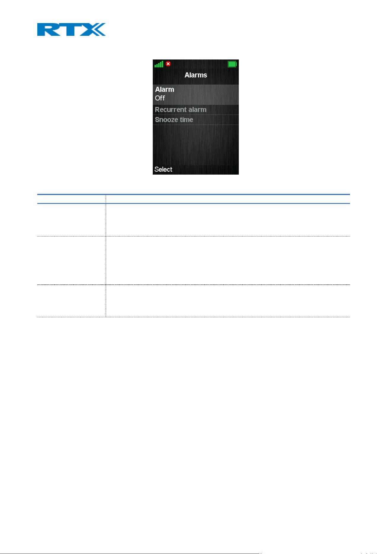
Figure 56 Alarm clock menu overview
PARAMETER DESCRIPTION
ALARM Schedule a one-time alarm clock. The time can be set by both the numeric keypad and
the up/down navigation keys.
NOTE: The alarm will occur at the specified time.
RECURRENT ALARM Schedule an alarm clock for a specific time and day of the week. The alarm will then
occur at the set time frame. The time can be set by both the numeric keypad and the
up/down navigation keys.
NOTE: This alarm clock is different from the first one. This means that the user can set 2
different alarms – 1x recurrent and 1x one-time.
SNOOZE TIME Set the time for suspending the alarm after it goes off.
NOTE: The snooze time takes effect only if the Snooze button is pressed when the alarm
occurs.
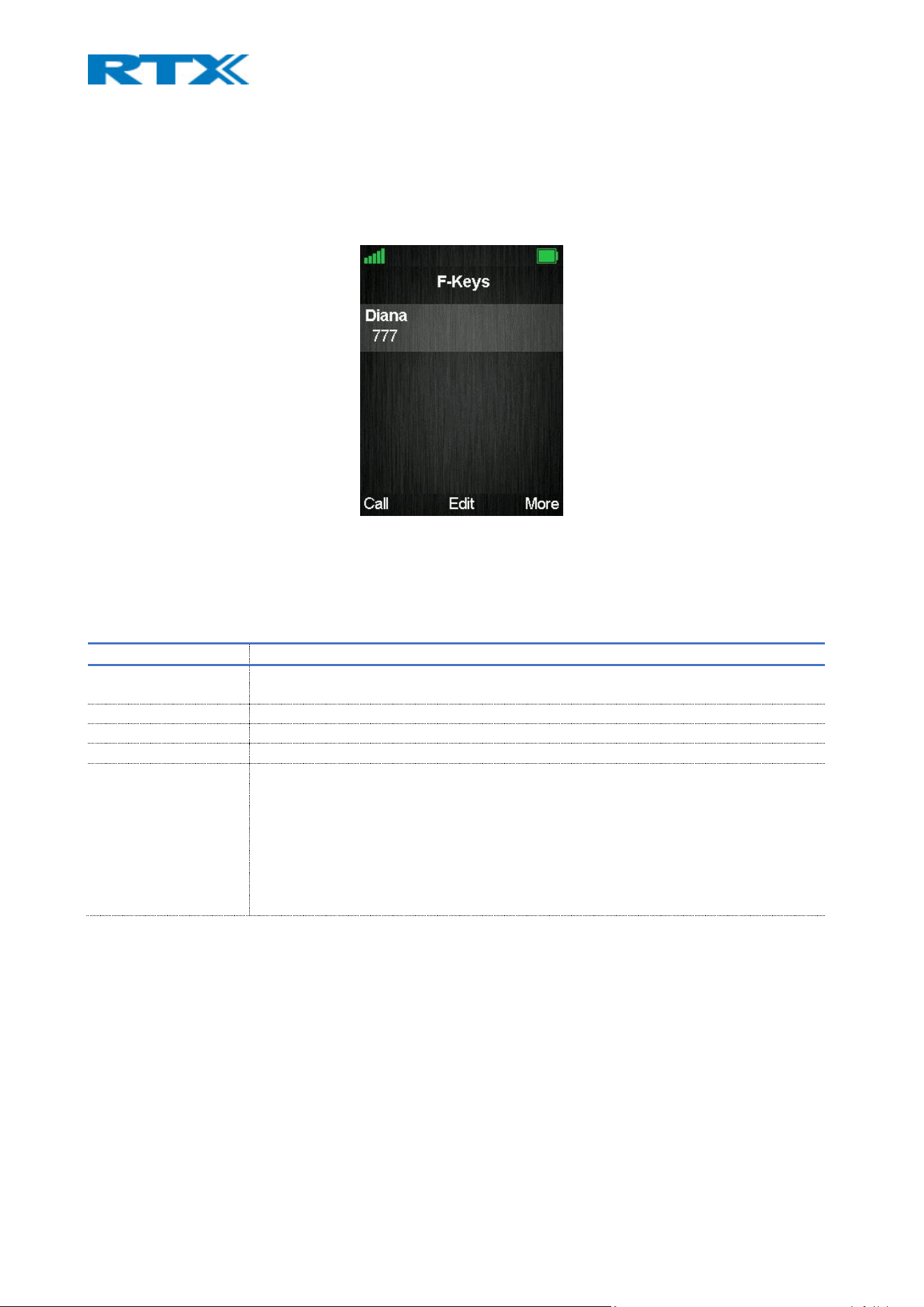
7.3.7 F-keys
This menu allows the user to add certain functional numbers to the list, for example a user’s mailbox or a
reception desk phone number. It represents another list for contacts used to ease the user in dialing specific
numbers (Fig.56).
Figure 51 F-keys menu overview
When entries are present, there are three available options assigned to the softkeys – Call (call the
highlighted entry), Edit (edit the entry’s details) and More (other available options, further described in the
following table).
PARAMETER DESCRIPTION
ADD F-KEY Provides the possibility to add a new F-key in the list by adding the name and number of
the entry
EDIT F-KEY Provides the possibility to edit the highlighted entry’s details
DELETE F-KEY Provides the possibility to delete the highlighted entry
DELETE ALL F-KEYS Provides the possibility to delete all entries from the F-key list
SPEED DIAL Provides the possibility to add an F-key to a speed dial number (2 – 9).
NOTE: The speed dial list stores both contacts from the Contact and F-Keys list. For
additional information, please refer to 7.3.1 Contacts
NOTE: The ‘1’ key is reserved for voicemail. Long key press on ‘0’ is used for starting a
normal dial string with ‘+’.
NOTE: RTX8431/RTX8436 has 4 extra keys (F1,F2,F3 and F4) to which an F-key can be
assigned as a speed dial key

7.3.8 Alarm list
This menu stores all the received emergency alarms on the handset and lists them to the user (Fig.57). The
different alarm types are defined on the base station (refer to 7.1.18 Alarm for further details).
NOTE: This menu is not supported by RTX8430, RTX8431 and RTX8436
Figure 58 Alarm list
The displayed alarms can be identified by the time they were received (date/time) and their alarm priority
(high, medium and low). If selected, the detailed content of the alarm is displayed. For further details about
the alarms and use case examples, please refer to Appendix 9.4 Alarm characteristics. For an alarm
configuration guide, please refer to 8.5 Alarms.
NOTE: Due to limited space on the handsets (max of 50 alarm messages), old alarms will be overwritten. This
means that as soon as the handset’s alarm storage is full, the new upcoming alarm will overwrite the oldest
one.
The alarm list is sorted by the following criteria:
• Read / unread (unread are displayed first)
• Priority (highest displayed first)
• Timestamp (newest are displayed first)
Depending on the alarm status there are several available options assigned to the softkeys of the highlighted
item – Select (open the alarm), Delete (delete the alarm), OK (acknowledge the alarm) and Reject (reject the
alarm).
STATUS ALARMS LEFT SOFTKEY CENTER KEY RIGHT SOFTKEY
ACCEPTED Select - Delete
NOT ACCEPTED Select OK Reject
NOTE: If the handset receives an alarm during call, a beep tone can be heard multiple times, indicating for
the alarm. Then the user can decide upon action for that alarm.
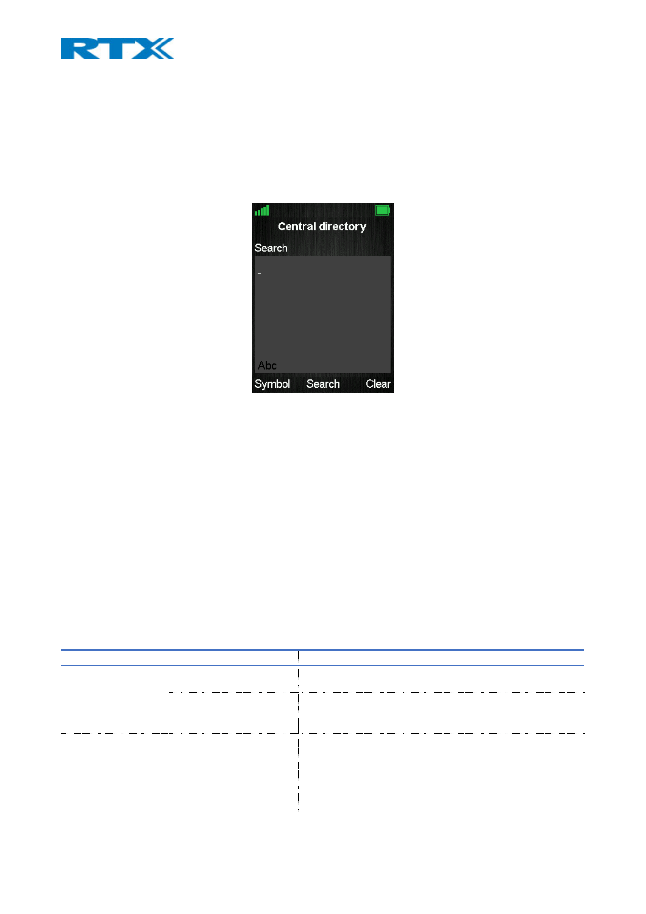
7.3.9 Central directory
This sub-menu contains the shared directory of contacts among the handsets in the system (Fig.58). When
enabled it can be found under Contacts in the Manu. Depending on the Central Directory mode, LDAP or
Local, the contact list can be uploaded in a different way. In the case of LDAP, the list is retrieved only from
a server, whereas if Local mode is used, then the list with contacts can either be retrieved from a server or
uploaded by the administrator via the base (refer to 7.1.13 Central Directory for more details).
Figure 59 Central directory overview
No matter the mode, the Central Directory menu displays very similar screens. The difference can be noticed
when opening the menu itself:
• If LDAP is used, a search screen is displayed. The user can either search for a contact in the list, by
typing a letter or the name of the contact, or continue with an “empty” search, by pressing the
middle softkey “Search” without any input (to display all the contacts from the directory)
• If Local mode is enabled, the list with contacts is displayed, from which the user can browse
through. The search mode can be accessed manually by pressing the middle softkey “Search”.
NOTE: If a blue/green arrow is visible on the right-hand side of the highlighted contact, this means that there
is more than one number added to the contact. It is possible to browse through the different numbers that
are assigned to a contact by using the right/left navigation keys.
Depending on the sub-menu that is opened – Search or List with contacts, there are several available options
assigned to the softkeys.
SUB-MENU SOFTKEY OPTIONS DESCRIPTION
SEARCH
Symbol Choose among various symbols that are not present on the
keypad of the handset
Search Search for a specific contact by typing their name or first
letters
Clear Delete the typed data from the search field
LIST WITH CONTACTS
Line Select the desired line from which to call the contact. The call
will then be routed via that line.
NOTE: A handset should be assigned to different extensions in
order to have a list with line options (refer to 7.3.4.8 Line for
more details)

Search Enter the search field
Back Return to the search field.
NOTE: This option is visible only in LDAP mode

8 Setup guides
This chapter aims to present various setup scenarios, such as configuring a dual/multi cell system, alarms,
multizone, etc., by providing a detailed step-by-step guide to the configuration process. The table below
summarizes the available setup guides in this section.
NOTE: The guides provide the general setup overview which aim to build the user’s understanding of setting
up the systems and using the related features. It does not provide customer specific setups.
GUIDE DESCRIPTION
MULTI CELL Guided steps on how to connect the bases in a multi cell chain
DUAL CELL Guided steps on how to connect the bases in a dual cell chain
CREATING EXTENSIONS AND
ADDING HANDSETS
Guided steps on how to create extensions and attach handsets to them
EASY REGISTRATION Guided steps on how to use the Easy registration feature
ALARMS Guided steps on how to create, assign and initiate alarms from a handset
MULTIZONE Guided steps on how to connect multi cell systems in zones
FIRMWARE UPGRADE
(BASE, HANDSETS,REPEATERS)
Guided steps on how to upgrade the firmware of the devices
PROVISIONING Guided steps on how to provision the base – via the server / via the user
interface
CENTRAL DIRECTORY
(LOCAL, LDAP AND XML)
Guided steps on how to configure the shared (central) directory with contacts
among the handsets
MULTILINE Guided steps on how to set multiple lines on one handset
DEBUGGING Guided steps on how to debug the devices and gather debug information for
RTX analysis.
8.1 Multi cell system
This sub-chapter describes how to setup a multi cell environment, by connecting bases into one system.
Please, follow the steps below to create your own network.
NOTE: It is possible to have RTX8660 and B760 in the same chain, but the features of the system will be
reduced to the ones of RTX8660. This means that if a user has a multi cell system with 50x B760 and adds 1x
RTX8660, the system will run on the RTX8660 features and exclude the extra ones from B760.
Step 1 Connect the base stations to a private network via the standard Ethernet cable (CAT 5).
Step 2 Access the first base by determining the IP address and then logging into the user interface
of the device (for more details refer to 6.1 Base station)
Once you have been authenticated, the browser will display the front end of the SME Configuration
Interface of the base (for more details refer to 7.1.1 Web navigation)
Step 3 To ensure a stable synchronization between the bases in the system, you must configure the
time zone. For this purpose, navigate to the Country page and configure the Country and Time server
settings (for more details refer to 7.1.11 Country). Press Save and Reboot.
TIP: To set the time server, you can press the Time PC button or use an internet time server (i.e. search
for pool.ntp.org in the web and use the specific pool zone for your country. For example, for DK it is
0.dk.pool.ntp.org)

NOTE: Make sure that the Time server is set on the base, else the dual/multi cell feature will not work.
This can be done by verifying that the Time Server IP address is still present in the field, after the reboot.
Step 4 Navigate to the Servers page and click on Add Server to add the PBX (SIP) server information.
This is the server that contains the extensions. As a generic setup, fill in the Server Alias and Registrar
fields. The rest of the parameters’ configuration depend on your desired setup and SIP server support
(for more details refer to 7.1.5 Servers). Press Save.
NOTE: Every service provider/customer should refer to their SIP server vendor on how to setup the PBX
(SIP) server itself
NOTE: Disable the NAT adaption parameter if the NAT function of the SIP aware router is not enabled.
Step 5 Navigate to the Extensions page and click on Add Extension. As a generic setup, fill in the Line
name, Extension, Authentication Username, Authentication password and Display name fields (for
more details refer to 7.1.3 Extensions). The rest of the parameters’ configuration depend on your
desired setup and the SIP server’s configuration itself. Press Save.
NOTE: To configure a dual/multi cell environment, it is important to create at least one extension on the base
station to define the primary base. Thus, registering a handset at this point is not a requirement. Registration
of devices is further explained in this guide (8. 3 Handset registration process), as soon as the dual/multi cell
system is configured.
Step 6 After creating an extension, you can now configure the base in multi cell mode. To do so,
navigate to the Multi cell page. Enable the Multi cell system parameter and type in a value for the
System chain ID (for more details refer to 7.1.14 Dual/Multi cell). Press Save and Reboot.
NOTE: After reboot, on the front page of the UI will be displayed the following System information status:
“Unchained Allowed to Join as Primary”
Step 7 Login to the base station that you wish to connect to the multi cell chain.
Step 8 Navigate to the Multi cell page, enable the Multi cell system parameter and enter the System
chain ID that you previously typed for the primary base station (refer to step 6). Press Save and
Reboot.
After reboot, the base will try to find and synchronize to the primary base station.
NOTE: It takes up to 5 minutes (synchronization time) to add a new base station to a multi cell system.
NOTE: Depending on the base’s role, the System information status will display Primary or Secondary on the
front page of the UI, as soon as the multi cell system is ready.
To add more base stations, repeat Step 7-8.
Step 9 Register your handsets by following the steps from section 8. 3 Handset registration process
8.2 Dual cell system
This sub-chapter describes how to setup a dual cell environment by connecting two bases into one system.
Please, follow the steps below to create your own network.

Step 1 Set up the primary base by following step 1-5 from the previous section 8.1 Multi cell system.
Step 2 The B700/730 bases follow the Plug-n-Play concept, meaning that the dual cell feature is
enabled by default and allows the second base to connect without any extra human effort. (To verify
this, you can navigate to the Dual cell page and ensure that the Dual cell system parameter is
enabled).
To add the secondary base to the primary, simply connect the second base station to a private network
via the standard Ethernet cable (CAT 5). After a while, it will automatically connect to the primary base.
NOTE: It may take up to 5 minutes (synchronization time) to add the base station to the dual cell system
NOTE: Depending on the base’s role, the System information status will display Primary or Secondary on the
front page of the UI, as soon as the dual cell system is ready.
Step 3 Register your handsets by following the steps from section 8.3 Handset registration process.
8.3 Replacing Primary Base station in a Dual cell system
Here is a step-by-step description of how to replace the Primary Base Station in your system in the cases
when that is necessary.
Step 1 Make sure to wait long enough for the Dual cell to reopen for registration.
Normally connection between bases is verified every 30 seconds. If verification fails, the status on the Dual
cell tab on the web UI will show the message: “Connection lost!”.
When the connection has been down for a defined amount of time (default is 15 minutes, but it can be
configured. See 8.3.1. Timeout configuration.) the base will switch to Ready for replacement mode. Then the
following message appears in the web UI of the functioning base, under System Information: “Replace the
other base”. At this point the Dual cell is open for new registrations, and we can replace the missing base.
NOTE: The replacement base needs to be in factory mode. If you are using a base that has been registered on
another system before, make sure to factory reset it beforehand. (Refer to 4.3.2 for more information on
resetting base stations.)
NOTE: All handset registrations are locked to the data primary base, meaning that if we remove it all handsets
will need to be reregistered. If the primary base is the one failing to connect, after a predefined amount of
time all registrations will be transferred to the secondary base and the system will reopen for the possibility
of a new base joining.
NOTE: In cases when specific parameters are different from the default ones, those has to configured before
adding the base to the chain. This might be network parameters, for example if static IP or VLAN is used. In
case the peer-to-peer Data Sync feature is used, it is necessary to enable that on the replacement base
beforehand and configure the IP of the remaining base.
Step 2 Connect the new base to the network and wait for it to join the chain.
The default behavior of bases in factory mode is to attempt to join any open system, therefore the new base
should connect to the reopened for registrations Dual cell system automatically. When the new base registers
successfully to the system it should be visible in the Dual cell tab on the web UI. It is advisable to make sure
the MAC address matches the new replacement base.

Once the base has been added to the chain, the user can choose which base to be assigned as primary and
which as secondary. The primary base will take over all the handset registrations.
NOTE: The system remembers the MAC address of the primary base. That is why it is very important when
replacing a primary to replace it with a new base (with another mac address). If for some reason user tries to
reset the primary base and add it again to the system as primary, that will create conflicts and will disturb the
system.
8.3.1 Timeout configuration
The time that the system waits before it reopens for registrations can be defined from the Dual cell tab in
the web UI of the base. Under the field Base registration timeout, you can type a value between 15 and
255 (in minutes). After that press Save so the system can save the changes.
8.4 Handset registration process
The following section provides a detailed guide on how to register your handset to the base station. The
process consists of first, enabling handset registration mode on the base, and then registering the device
itself. The UI of the Extensions page is different between the bases. Therefore, depending on the type of
base that is used, the handset registration steps vary. Please follow the steps accordingly:
8.4.1 Enable registration mode for B760.
Step 1 Login to the base and navigate to the Extensions page.
Step 2 Create an extension by following Step 5 from the previous section 8.1 Multi cell system.
NOTE: If extensions are already present, you can skip this step
Step 3 Select the check box of the extension which you wish to register the device to, and then
click on Register Handset (s).
The base now displays Enabled in the Handset State column and is open for handset registration for 5
min.
TIP: If you wish to register more handsets, click on Check All and then Register Handset (s). This will enable
registration mode for all extensions, meaning that you will only need to follow the steps from 8.3.3 Register
a handset to add the handsets to the base system.
8.4.1.1 Setting up multiline
Step 1 Login to the base and navigate to Extensions page.
Step 2 Create an extension by following Step 5 from the previous section 8.1 Multi cell
system.
NOTE: If extensions are already present, you can skip this step
Step 3 Navigate to the Extensions page and click on Add Extension. As a generic setup, fill
in the Line name, Extension, Authentication Username, Authentication password and Display
name fields (for more details refer to 7.1.3 Extensions). In the field Handset, instead of New
Handset use the drop-down menu to choose the existing handset you want to assign the new
line to. The rest of the parameters’ configuration depend on your desired setup and the SIP
server’s configuration itself. Press Save.

Step 4 The extension will now show in the extension list with the same Idx and IPEI as the
handset selected.
NOTE: If the handset has been already registered, it has to be rebooted before the changes to take effect.
8.4.2 Enable registration mode for B700/730.
To enable registration mode on the B700/730, you first need to create slots for the handsets and then enable
handset registration.
8.4.2.1 Create handset slots.
Step 1 Login to the base and navigate to the Extensions page.
There are two ways which you can use to create handset slots.
a. Via the Extensions page (while adding an extension)
i. Create an extension by following Step 5 from the previous section 8.1 Multi cell
system.
NOTE: If an extension is already present and you wish to assign a handset to it, click on the extension to
open the editor’s window.
ii. On the right-hand side select the check box for adding a new handset. Press Save
b. Via the Handset tab page
i. Click on the Handset tab to enter the Handset page
ii. Click on Add Handset (s). A new window will open. Click on Save
8.4.2.2 Setting up multiline
Setting up a multiline means assigning more than one extension to a handset. To register a handset to a
system with an active multiline feature follow the steps below:
Step 1 Register handset by following the steps described in
Step 2 Add a multiline to a handset by creating a new extension, but instead of Add Handset in the
Select Handset(s) menu, select the existing handset that you want to add a multiline to.
Step 3 The extension will now show in the Extension list with a new Idx but the same IPEI. In the
Handset tab we can see the Idx will be the same and the Extension column will show the available
extensions for this handset.
NOTE: If the handset has been already registered, it has to be rebooted before the changes to take effect.
The handset will now have two numbers. When making a call the user can chose which Line to call from. The
way that happens depends on the software version of your handset.
One handset will be able to support up to 4 lines, but only 2 call appearances. The limitation of maximum 20
handsets in the Single cell system is maintained, and the maximum number of SIP registrations that the base
station can handle, is maintained. With 4 lines per handset maximum number of devices registered in the
system is 5. With 1 line per handset maximum number of devices registered in a single cell system is 20.

8.4.2.3 Enable handset registration.
Follow the steps below to enable handset registration mode:
Step 1 On the Extensions page, click on the Handset tab to enter the Handset page.
Step 2 Select the check box of the handset slot which you wish to register the device to, and then
click on Register Handset (s).
The base now displays Enabled in the Handset State column and is open for handset registration for 5
min.
TIP: If you wish to register more handsets, click on Check All and then Register Handset (s). This will enable
registration mode for all handset slots, meaning that you will only need to follow the steps from 8.3.3
Register a handset to add the handsets to the base system.
8.4.3 Register a handset.
After enabling the handset registration mode, it is now possible to register the device.
Step 1 Enter the menu of the handset – Connectivity – Register – Select and type in the Access Code
of the base.
NOTE: The Access code (AC) is used to allow the handset to register to the base station. By default, the value
is 0000, but the administrator can change the AC to another numeric value. This can be done via the
Extensions page on the base station (See 7.1.3 Extensions for more details).
The handset indicates that it is trying to register to the base by displaying Registering in idle screen.
Step 2 As soon as the handset registers, the extension number will appear on the handset and the
base station will display the IPEI number of the device on the Extensions/Handset page.
NOTE: To verify that the handset has been registered to the base, you need to refresh the Extensions /
Handset page, as it will not update automatically.
Step 3 Verify that the handset is SIP registered by finding a SIP Registered state under the State
column.
8.4.4 Easy registration
The B700/730 device is currently the only base station that supports the new feature “Easy registration”. It
enables the user to add new handsets and repeaters without having to open the base webpage. This means,
that the user can physically enable the registration mode by rebooting the base station via the UI or by
pressing the button (until orange LED is shown), or by using the “Easy registration” menu on the RTX843x
handset.
NOTE: To enable this feature, please contact RTX.
NOTE: Access code must be 0000 for the feature to work.

8.4.4.1 First registration overview
When the administrator first unpacks the system and powers on the base(s), the base(s) will open for
registration for 120 seconds. If the registration process times out, the user can easily restart the process by
rebooting the base or by unplugging and plugging the power connection. When the first device has been
added, the system will close for registration, and the administrator needs to follow the normal registration
flow, as described in the following sections.
NOTE: The base must be provisioned with extensions/SIP registrations to be able to add a device
8.4.4.2 Enabling registration mode
Enabling “Easy registration” to add a new device can be done by the following two ways. In either case,
remember that this will require the base to already be provisioned with extension/SIP registration data for
the allowed handsets.
• Pressing the reset button on the base for two seconds, which will reset the base. This is only if you
have not DECT registered the first handset.
• Using the Easy Registration menu option in the RTX843x handset. This option is found in the
“Connectivity” menu of the handset.
For every successfully registered device (besides the first one), if the user acknowledges the registration
success, the base will count 2 extra minutes to allow the user to add more devices. Else, if not acknowledged,
the base will close the registration “window”.
Please have in mind that the “Easy registration” feature can be enabled only by devices supporting the
feature and namely B700/730 and RTX843x. Once enabled, different models of handsets can be registered.
8.4.4.3 Registering devices
8.4.4.3.1 Handsets
As previously mentioned, once the base station is unpacked and powered on, it enters a registration mode
for 120 seconds. In order to establish a connection, the base station must be already provisioned with
extension/SIP registration data for the upcoming handsets/repeaters. While the base is open for registration,
the LED will blink to indicate the “open” state. Meanwhile, the administrator must power on an RTX8431
handset which has no current registration. A “registering” screen will be displayed after booting of the
handset is completed. The handset will automatically register to the base station unless the user presses
“Cancel” to stop the registration process. If the registration process of 120 seconds has timed out, the user
can easily restart the process by rebooting the base or by unplugging/plugging the power connection. As
soon as the first handset has been registered, the user may continue adding handsets following the normal
procedure mentioned below.
After having registered handset number one to the base station, the system is now up and running. There
are two ways of registering a second handset:
1. Brand new RTX843x - In order to connect a second unpacked RTX843x handset, the administrator
should go to the “Connectivity” menu of the already registered RTX843x device and select the
“Easy registration” feature (please see the screenshots below). The system will enter the
registration mode and the administrator can then power on the new handset number two. The
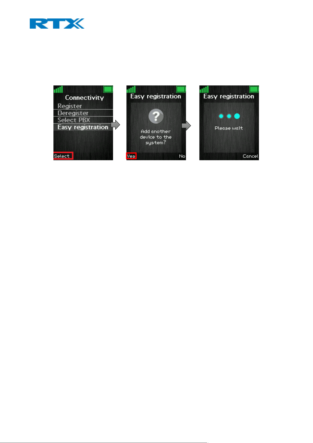
handset enters immediately registration mode and after a moment, it will be registered to the base
station. The administrator will see a confirmation screen on both handsets number one and two,
where the user can compare if the IPEI match. After pressing “Okay”, the system opens again the
registration window for 120 seconds where the user can add another handset.
2. Other handsets – The administrator must go to the “Connectivity” menu of the already registered
RTX843x device and select the “Easy registration” feature (please see the screenshots above). The
system will then enter registration mode.
To register other handset models, that do not support the “Easy registration” feature, the
administrator must go to the “Connectivity” menu of the handset that must be registered, select
“Register” and type in the “Access code”. After a while, the second handset will be registered.
NOTE: If a new device is not added successfully to the system, a popup error message will be displayed,
containing one of the following errors:
- “Registration failed.”
- An error text to serve as hint to the user for solving the issue
- An error code to serve the specialized technicians with extra debug information
8.4.4.3.2 Repeaters
The feature also allows the registration of repeaters to the system. To register a repeater, enter the “Easy
registration” menu from the RTX843x handset and allow new devices to the system (for more details, please
see the previous section, point 2). Power on the repeater. As soon as the handset’s screen has displayed
success, the user may compare the IPEI from the screen of the device with the IPEI on the repeater’s label.
By doing so, the user will make sure that the correct device has been added.
NOTE: To be able to register a repeater, it should be already provisioned/added in the base station as a device.
8.5 Firmware/Picture upgrade procedure
All devices can be upgraded via the user interface (Firmware update page), or via provisioning. In addition to
this, both HTTP and TFTP can be used to handle the upgrade process. While upgrading the handset with a
new firmware/picture, the progress can be monitored on the Extensions page under the FWU Progress
column. The progress is displayed in % and as soon as the file upload is done, the column will display a

message “Waiting for charger”. The user must then place the handset in the cradle to overwrite the old
firmware/picture with the new one. The handset is ready to be used as soon as it reboots.
NOTE: The handset must not be removed from the charger until the FWU Progress column on the Extensions
page displays “Done” or “Off”.
NOTE: If the new image is not present on the handset after the reboot, the user must reset the settings of the
device (Settings – Reset settings)
For a detailed firmware upgrade procedure, please refer to RTX’s document Firmware update guide. (9430-
8660-HS).pdf
8.6 Alarms
The following sub-chapter describes how to setup alarms on the handsets. Before proceeding to the
configuration, it is important to note that when an alarm is generated, it can be delivered in 2 ways - either
by call, or by message. Depending on the desired transmission, the configuration is different. The next
sections present a step-by-step guide for setting up both scenarios.
NOTE: Not all handsets can generate/receive alarms. Therefore, carefully review which handsets support the
feature (refer to 7.1.18 Alarm for more details)
8.6.1 Via a message
To be able to send and receive alarms in a message format, an alarm server is needed. Therefore, before
configuring the alarms on the DECT system, please make sure that an alarm server is present.
NOTE: This guide does not cover alarm server configuration. It is up to the customer to decide which server
solution to use for handling the alarms.
As soon as an alarm server is set up, you can proceed to the alarm configuration on the DECT system. Please,
follow the steps below.
Step 1 Enter the base station’s web UI and go to the Alarm page
Step 2 Create the desired alarms by configuring the settings on the page (for further details on the
settings, please refer to 7.1.18 Alarm). Press Save
Step 3 Navigate to the Extensions page and select the IPEI of the handset, which you wish to assign
an alarm to. The handset editor’s menu will open.
Step 4 Navigate to the Alarm Profiles section where the available alarms are listed (the ones you
configured in step 2). Select the checkbox of the alarm which you wish to assign to the given handset
and press Save.
Repeat steps 3-4 to assign alarms to other handsets
Step 5 Go to the Management page and navigate to the Text messaging section. Enable the Text
messaging setting, type in the alarm server address in the Text messaging & Alarm Server field and
edit the rest of the settings (refer to 7.1.7.5 Text messaging for further details on the fields). Press
Save

Step 6 Generate an alarm to verify that it will be distributed and received by the counterpart. In
case the alarms do not work, please reboot the system/devices and try again.
8.6.2 Via a call
It is possible to send and receive alarms in a call format. This means that all communication is handled by the
DECT base and no message server is needed.
Step 1 Follow steps 1-3 from the previous section (8.5.1 Via a message)
Step 2 Edit the Alarm line and Alarm Number fields (refer to 7.1.4 Handsets for further details on
the settings)
Step 3 Navigate to the Alarm Profiles section where the available alarms are listed (the ones you
configured previously). Select the checkbox of the alarm which you wish to assign to the given
handset and press Save.
Step 4 Generate an alarm to verify that it will be distributed and received by the counterpart. In
case alarms do not work, please reboot the system/devices and try again.
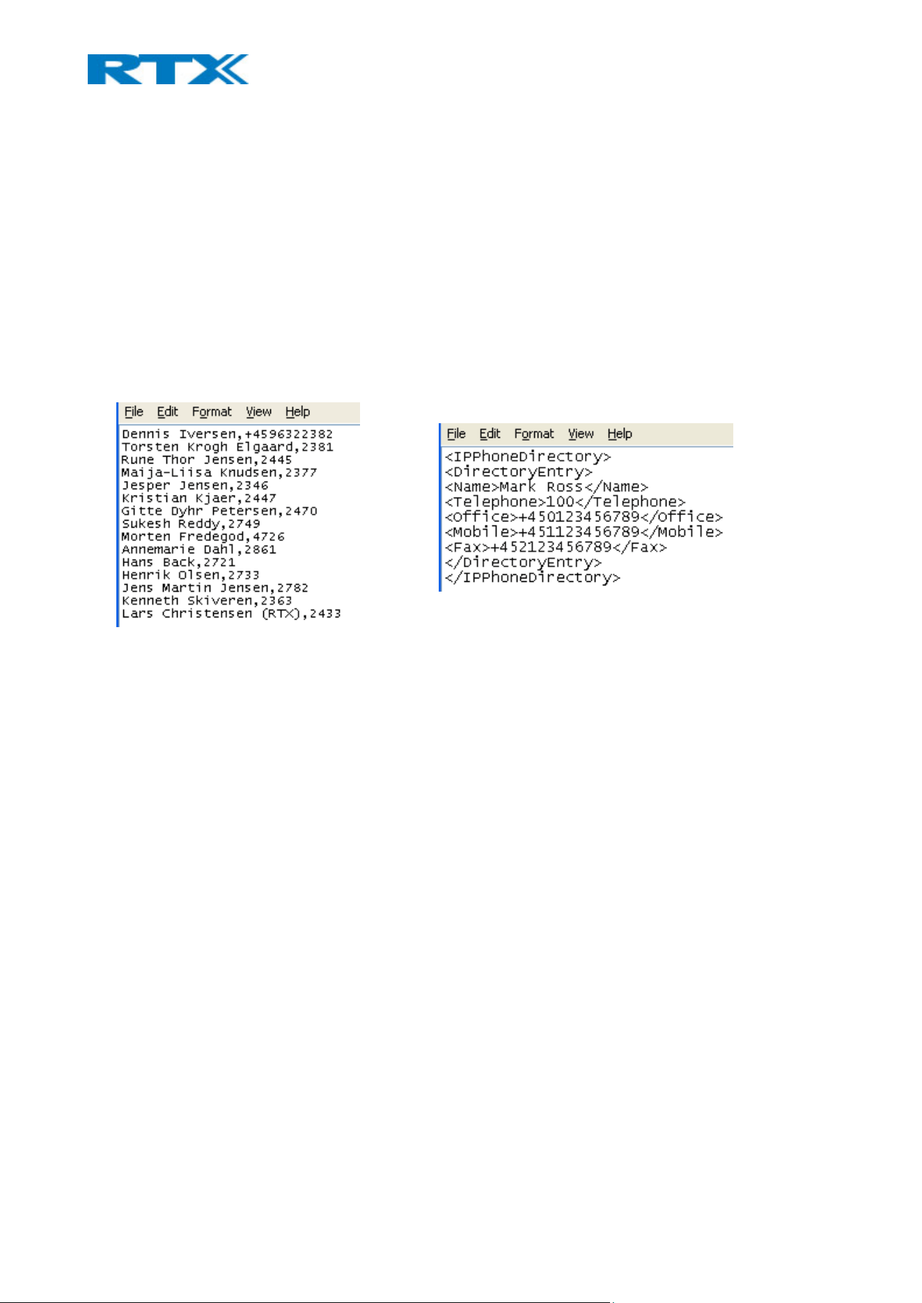
9 Appendix
9.1 Contact list structure
As previously mentioned, the administrator can upload a contact list either to a selected handset or share
the list as a local central directory. The supported file formats are .csv, .txt and .xml. This section provides
details on the structure of the contact list, both in text (Fig.59) and xml format (Fig. 60).
NOTE: Contact name must not contain more than 23 characters and contact number must not contain more
than 21 digits.
NOTE: When using a server to import the file (via the Central Directory page – Local), remember to set the
transfer protocol via the Management page – Settings - Management Transfer Protocol
.txt file limitations:
• Contact name must NOT contain “,”
• Contact number digits must be: +0123456789
• Contact number does not support SIP-URI
• Spaces between name section “,” and number section are not supported.
9.2 B760-RTX8660 Mixed mode
B760 can be added to existing systems using RTX8660 base station. Even though the two base stations will
be able to co-exist in the same multi cell setup, the system will be set to some limitations. This means that
the multi cell will disable the features of B760, that are not supported by RTX8660, and run-on mixed mode
but with limited to RTX8660 features.
NOTE: LAN SYNC will not work in mixed mode.
NOTE: RTX8660 cannot be added to an existing B760 Multi-cell. Only B760 can join an RTX8660 system.
The system will display a warning message on the Home/Status page (Fig.61)
Figure 60 .csv or .txt format
Figure 52 .xml format
Figure 53 Warning mixed mode message.
9.3 ELIN and HELD support
9.3.1 National emergency numbers
COUNTRY DEFAULT NATIONAL EMERGENCY NUMBERS
Australia 000
Austria 112, 122, 133, 144
Belarus 01, 02, 03
Belgium 112, 100, 101
Bosnia 124, 92, 93, 94
Brazil 190, 192, 193
Bulgaria 112, 150, 160, 166
Canada 911
China 110, 112, 119, 120, 122
Croatia 112, 92, 93, 94
Cyprus 112, 999
Czech 112, 150, 155, 158
Denmark 112
England 112, 999
Estonia 112, 110
Finland 112, 10022
France 112,15,17,18
Germany 112,110
Greece 112,100,166,199
Holland 112
Hong Kong 999
Hungary 112, 104, 105, 107

Iceland 112
Ireland 112,999
Israel 100, 101, 102
Italy 112,113,115,118
Kazakhstan 03
Latvia 112, 01, 02, 03
Lithuania 112, 01, 02, 03
Luxemburg 112,113
Malta 112, 191, 196, 199
New Zealand 111
Norway 112, 110, 113
Poland 112, 997, 998, 999
Portugal 112
Romania 112, 961, 962, 955, 981
Russia 112
Serbia 92, 93, 94
Slovakia 112, 150, 155, 158
Slovenia 112, 113
South Africa 107, 10111, 10177
Spain 112, 061, 062, 080, 091
Sweden 112
Switzerland 117, 118, 144
Taiwan 110, 119
Thailand 191, 199, 112, 1669, 1155, 1554, 1860
Turkey 112, 110, 155
Ukraine 118, 01, 02, 03
United States Of America 911

9.3.2 Prerequisites for ELIN & HELD support
The E911 makes use of location information extracted from LLDP for HELD data and it is used when creating
HELD requests towards the RedSky server. Therefore, the network setup must support LLDP and be
configured on RedSky.
ELIN must be provided from the local exchange carrier (LEC) and if an SBC is used, this must be configured
for emergency calls with ELIN numbers. Whether reuse of the same ELIN should be used throughout the
Enterprise is for the local IT/Security policy to decide. Having only 1 ELIN restricts the amount of
simultaneous emergency call(s) to 1.
Administrator needs to populate the Location Information Server (LIS) database with a network wire map,
which maps the Enterprise's network elements to civic addresses.
NOTE: The bases do not support ELIN information obtained via LLDP
NOTE: The bases do not support Location by Value
9.3.3 Planning considerations for E911 ELIN/Custom UUID
The following planning considerations must be considered when configuring E911 ELIN/Custom UUID:
• Verify the local or national regulations with regards to the number of ERLs and the maximum area
in square meters allowed per Emergency Response Location (ERL).
• Ensure that the location is sufficiently specific to allow dispatched emergency services to rapidly
locate the 911 caller.
• Consider assigning up to five ELINs per ERL.
• Request your phone service provider to assign you X amount of phone numbers that you will
designate as ELINs.
• Ensure to maintain an updated LIS database. For example, if you change or create a new network
element.
• As a general rule, subnets that resolve to corporate virtual private network (VPN) connections
should be excluded from the LIS. This is because typically there is not a civic address that can be
associated to the subnets that correlate to where the users are located.
9.4 Alarm characteristics
An alarm consists of the following characteristics:
• Priority
• Confirmation type
• Number of rings
• Reference number
• Text
• Status
An incoming alarm has 9 priorities, from 1-9, where Priority 1 is considered as the most important and Priority
9, the least important. The priority is first used to determine which message to display to the user, if there
are more than one unread alarms present on the handset. When an alarm is displayed to the user, the alarm
is grouped in 3 groups. Priority 1-3 is considered high priority, 4-6 considered medium priority and 7-9 is
considered low priority. Alarms are presented to the user depending on which of the 3 groups their priority

is. This means that the played melody and the used colour in the display (both configurable by the user on
the handset) depend on the group.
Confirmation type is a number between 0 and 2. It indicates how much feedback communication there is
from the base / handset to the message server. Confirmation type 0 confirms that the message is delivered
to the base (one message back to the message server). Confirmation type 1 confirms that the message is
delivered to the base + the message is delivered to the handset (two messages back to the message server).
Finally, Confirmation type 2, three messages are delivered back to the server.
An alarm can be defined by the number of rings, which is a number between 0 and 9. It indicates how many
times the handset should play the melody that corresponds to the alarm message presented to the user. 0
means that the melody is infinity number of times.
Reference number is a unique number for each alarm and is used to identify the alarm. If an alarm should be
replaced or deleted by the message server, then this number is used to identify the specific alarm.
Text is the message string presented to the user. It is a string between 1 and 160 characters.
Status is a number that indicates what to do with the received message. If this number is 10, then an already
received alarm message (identified by its Reference Number) should be deleted. Otherwise, it is treated as a
new message or a message to be replaced.
9.4.1 Receive alarms.
An alarm is received and stored in the handset. If the user presses the on-hook (red) button, the alarm is
considered as “unread”. Else, if the user presses one of the softkeys related to the alarm (Select, OK, Reject,
Delete) the alarm is considered as “read”. The alarm with highest priority, which has not been read, is
displayed to the user. The number of rings is specified by the message server. If there are more unread alarms
to come with the same priority, then the most recently received of them will be displayed. When the current
alarm has been accepted/rejected, and there are more unhandled alarms, the handset will display next the
most recent alarm with the highest priority.
The priority of different scenarios is set on the server. The colour of the alarm represents what priority the
alarm has. For priority 1,2 and 3, the top bar (Alarms) is red. For priority 4,5 and 6, the top bar is yellow. For
priority 7,8 and 9 (or higher), the top bar is green.
ALARM COLOR ALARM PRIORITY
RED High
YELLOW Medium
GREEN Low
NOTE: RTX handset supports 3 different colors, but different servers might support more priorities
When an alarm is displayed, the softkeys have the following functions:
CONFIRMATION TYPE LEFT SOFTKEY CENTER KEY RIGHT SOFTKEY
0,1 (UNREAD) Call OK Delete
2 (UNDREAD) Call OK Reject
0,1,2 (READ) Call OK Delete

If the message server has sent a number to call back, then the left softkey will display “Call”. If the left
softkey is pressed, then the number is dialed.
9.4.2 Use case: Receive two alarms (priority 1, then priority 2)
An alarm of priority 1 is received and no action is performed by the user – neither OK / Delete (confirmation
0 and 1) or OK / Reject (confirmation 2) softkeys are pressed. The current state of the display might be in-
call, showing the alarm or in idle.
An alarm with priority 2 is received.
The received priority 1 alarm is displayed again because it has higher priority than any other unread alarm.
The number of rings is specified by the message server for the priority 1 alarm. If priority 1 alarm is already
displayed and alerting, it will continue to be displayed / alerting. However, it can be heard that priority 2
alarm is received.
9.4.3 Use case: Receive two alarms (priority 2, then priority 1)
An alarm of priority 2 is received and no action is performed by the user – neither OK / Delete (confirmation
0 and 1) or OK / Reject (confirmation 2) softkeys are pressed. The current state of the display might be in-
call, showing the alarm or in idle.
Afterwards, a priority 1 alarm is received.
The received priority 1 alarm is displayed, because it has higher priority than any other unread alarm. The
number of rings is specified by the message server for the priority 1 alarm.
9.4.4 Use case: Receive two alarms with same priority
An alarm of any priority is received, and no action is performed by the user – neither OK / Delete
(confirmation 0 and 1) or OK / Reject (confirmation 2) softkeys are pressed. The current state of the display
might be in-call, showing the alarm or in idle.
Afterwards, another alarm of the same priority is received.
In this case, the last received alarm will be displayed. The number of rings is specified by the message server
for the last received alarm.
9.4.5 Delete alarms
The following sections represent the various ways of deleting alarms.
9.4.6 Upon server request
The following scenario is taken into consideration:
An alarm is present, and the message server requests the alarm to be deleted. The request to delete an
alarm is received. Thereafter, the alarm is removed. This means that if the alarm, which needs to be removed,
is currently being displayed / alerting, it will not be displayed anymore, and it will stop ringing.
9.4.7 From the alarm list
If the user enters the Alarm list menu and deletes an alarm, the alarm will be deleted from the list and the
user will remain on the menu.
It is possible to delete all types of alarms (confirmation type 0, 1 and 2) at any time.

The message server does not receive any information regarding the successful/unsuccessful delete of the
alarms.
9.4.8 Replace alarms
The following scenario is taken into consideration:
An alarm is present, and the message server requests the alarm to be replaced. The old alarm is removed,
and the replacing alarm is treated as if it is a new alarm. If the alarm to be replaced is the one currently
alerting, then the alerting will stop. The unread alarm with the highest priority (lowest number) will start
alerting – this might be the same alarm or a different one.
9.4.9 Receiving an alarm while handset is not in idle
If an alarm is received during a call, a silent beep will be heard, which will not interrupt the conversation.
If the handset is not in idle and receives an alarm, the device will treat the alarm as if the handset is in idle.
This means that the alarm will pop-up on the screen. For example, if the user is composing a normal SMS,
then the SMS will be stored as a draft before the alarm is handled.
9.5 Provisioning
For a quick guide on the provisioning process, please refer to 7.1.22 Configuration.
9.6 Calls Operations
In this section the different types of calls and call handling will be described.
9.6.1 Incoming Call
As the handset receives an incoming call an alerting screen will be displayed. This will be accompanied by a
ring signal and/or a vibrating handset according to the respective settings on the handset.
The calling party’s handset number will be shown in the middle of the display, and an additional name is
displayed if the calling party’s handset number is stored in the local phonebook.
When in active call some handset models show small icons right under the Status bar that visualize if the
call is incoming, outgoing or on hold.
NOTE: In case of multiline feature being used some handset models display the line used in the top right
corner. The same feature also shows in different tabs the calls on hold and the active call and allows the
user to switch between the tabs. Because of the difference in screen size between the models, that feature is
not available on all models.
9.6.1.1 Answering an incoming call
To answer an incoming call, press the green “Off-hook” button, or press the “Loudspeaker” key to answer
the call in a speaker mode.
NOTE: When “Auto answer” is set to “Automatic” an incoming call is answered automatically after one ring
signal. If “Auto answer” is set to “Any key” an incoming call can be answered by pressing any key on the
keypad, and not just the green “Off-hook” button.
9.6.1.2 Reject an incoming call
It is possible to reject an incoming call by pressing the right softkey “Reject” when receiving an incoming
call. This way the calling party will receive a busy tone, and “User busy” displayed on the screen.

NOTE: An incoming call can also be rejected by pressing the red “On-hook” key.
9.6.1.3 Silencing an incoming call
When the handset is alerting it is possible to press the left softkey “Silent” whereas the handset will
continue to alert, but without any heard ringing.
9.6.1.4 Ending a call
To end an ongoing call, press the red “On-hook” key, and the call will be terminated. The duration of the
call is shown in the display. Furthermore, this duration time can also be viewed from the call list where the
call is stored.
NOTE: If one call is active and another call is on hold, then the active call will be terminated when pressing
the red “On-hook” button, and the handset automatically returns to the call on hold, i.e., the call on hold is
now active, and the user must press the red “On-hook” button again to terminate this call.
9.6.2 Initiating a call
A call can be initiated from different locations on the handset:
o By entering the number directly from idle
o From the “Contacts” menu
o From the “Calls” menu
o From the “Central Directory”
How to initiate a call from these different directories is explained in the following sub sections.
9.6.2.1 Initiating a call from Idle
When initiating a call, it must be done according to the following:
Step 1 Enter the number of the person you want to call when the handset is in idle.
Step 2 Press the green “Off-hook” button to call the number.
Step 3 The handset will show “Calling” on the screen and the number we are calling to.
Step 4 When the counterpart answers the call, the screen will show “Connected”, and the two
parts are now in call.
9.6.2.2 Line call
If the handset is used in a multiline environment, it is possible to make a call from different lines by
pressing the middle softkey “Line” and choose the line according to which system the call should be made
from.
9.6.2.3 Initiating a call from Contacts
To initiate a call from the contact list, there must be contacts added to the local phonebook. When this
prerequisite is met a local contact can be called by highlighting the contact in the contact list, and then
pressing the left softkey “Call”, or pressing the green “Off-hook” button.
NOTE: The list of local contacts can be reached from the menu “Contacts” or directly from idle by pressing
the left softkey when in idle.

9.6.2.4 Initiating a call from Calls
The number of an outgoing, incoming, or missed call can be called directly from the call list by highlighting
the number and pressing the left softkey “Call” or the green “Off-hook” button to call the entry.
NOTE: The “Calls” list can be reached from the menu “Calls” or directly from idle by pressing either the
green “Off-hook” button or the right softkey when in idle.
9.6.3 Call Holding/Retrieving
It is possible to hold a call which means that the one party of the call is put on hold and cannot hear the
other party but can only hear a repeated short tone on hold until the call is retrieved.
Step 1 To put the counterpart of the call on hold press the left softkey “Hold”, and this party is put
on hold.
Step 2 To retrieve the call, and thereby continue the conversation, press left softkey “Retrieve”
which is only showed on the screen when the other party of the call is put on hold.
NOTE 1: If one call is active and another call is on hold, then the active call will be terminated when pressing
the red “On-hook” button, and the handsets automatically returns to the call on hold, i.e. the call on hold is
now active, and the user must press the red “On-hook” button again to terminate this call.
NOTE 2: When the counterpart is put on hold it is also possible establish a second call and make a
conference, swap or transfer which will be explained in the following sections.
9.6.4 Attended and Unattended Transfer of a Call
When in an ongoing call, it is possible for either party to transfer the call, either attended or unattended, to
another handset.
9.6.4.1 Attended call transfer.
In an attended transfer the party that call is transferred to, is called before the transfer is made. The
procedure to do this is as follows.
Step 1 Initiate a call with a counterpart, so that the handset displays “Connected” as shown
below.
Step 2 Press the right softkey “Transfer” on either of the handsets in call, and the counterpart of
the call is put on hold.
Step 3 Enter the number that the transfer should be made to and press the green “Off-hook”
button.
Step 4 A ring back tone is heard, and a third party is called.
Step 5 As the third party answers the call the handset user initiating the transfer will show
“Connected” on the screen.
Step 6 To make the transfer after the third party has answered the call, press the right softkey
“Transfer”, and the call is transferred so that the second and third party are now in call, and “Call
ended” is displayed on the handset’s screen.
NOTE: It is also possible to make an attended transfer by pressing either the left softkey “Hold”, or the
middle softkey “Conf.” instead of pressing the right softkey “Transfer” in step 2.

9.6.4.2 Unattended call transfer
When making an unattended transfer, the call will be transferred directly to a third party without the party
initiating the transfer needing to call this third party before the transfer.
1. Initiate a call with a counterpart so that the handset displays “Connected”.
2. Press the right softkey “Transfer” on either of the handsets in call, and the counterpart of the call is
put on hold.
3. Enter the number that the transfer should be made to, and press transfer.
4. This will end the call on the first handset party (screen will show “Call ended” message), and the
second party will stop being on hold and hear a ring back tone instead which indicates that this
handset is now calling the third party.
5. When the third party answers the call, an unattended transfer has been made and the second and
third party are now in call.
NOTE: As with attended transfer, it is also possible to make an unattended transfer by pressing either the
left softkey “Hold”, or the middle softkey “Conf.” instead of pressing the right softkey “Transfer” in step 2.
9.6.5 Swap between two calls
It is possible to swap between two calls. In this case, one party will be in ongoing call, and the second party
will be on hold. i.e., “Swap” means that it is possible to toggle between these two parties.
Step 1 Initiate a call with a counterpart so that the handset displays “Connected”.
Step 2 Put this call on hold by pressing the left softkey “Hold”.
Step 3 Enter the number of a second party and press the green “Off-hook” button.
Step 4 A ring back tone is now heard in the handset as the second party is alerting. As the second
party answers the call a “Connected” screen as above is displayed.
Step 5 By pressing the left softkey “Swap” the ongoing call is now between the first party whereas
the second party is now put on hold.
Step 6 From this point, it is possible to toggle between the two parties by pressing “Swap”. For
each time that “Swap” is pressed a toggle is made between the two external parties, and the
“Connected” screen shows the phone numbers to indicate if it is the first or second call that is
ongoing.
9.6.6 Call waiting
When two parties are in call it is possible to receive a call waiting on one of the handsets which means that
a third-party calls one of the two parties already in call. During a call waiting two short beeps are heard
every three seconds in the handset receiving the call waiting, and “Alerting” is displayed on the screen
together with the number or name of the contact (in the case when this contact is present in the local
phonebook).
It is possible to reject the call waiting with the right softkey “Reject”, and hereby continuing the ongoing
call with the first party.
If the call party wants to answer the call waiting the green off-hook key should be pressed. On the screen it
will be displayed “Connected” together with the number or name of contact.

NOTE: In case of multiline feature being used some handset models display the line used in the top right
corner. The same feature also shows in different tabs the calls on hold and the active call and allows the
user to switch between the tabs. Because of the difference in screen size between the models, that feature is
not available on all models.
9.6.7 Conference Call
In a conference call there are always at least three parties in the same conversation. Hereby, this feature
enables the user to have an ongoing call with more than one person – the parties in a conference call are
called participants.
9.6.7.1 Establishing a conference call
In the following, it is described how to establish a conference call between three parties.
Step 1 Initiate a call with a counterpart so that the handset displays “Connected” on the screen.
Step 2 Press the middle softkey “Conf.” to start a conference call.
Step 3 The second party is put on hold and will hear a tone on hold.
Step 4 Enter the number of the party to invite to the conference and press the green “Off-hook”
button to call this participant.
Step 5 When the called party answers the call the second party is still on hold, and the
conversation is only between the third party and the first party, i.e., initiator of the conference.
Step 6 To start conversation between the three parties – i.e., a conference – press the middle
softkey “Conf.”
Step 7 The “Conference” screen as seen above will then be displayed, and the three participants
will be in a conference call. Thereby the conversation is between all three parties.
NOTE 1: When using a Conference server, the procedure is slightly different from the steps above. If a
Conference server is used, you need to start the conference with the second party before you press “Hold”
and call the third party. If you follow the standard procedure by immediately pressing “Hold” and calling the
third party without initiating first the network-based conference, the Conf key will not be present on the
display.
NOTE 2: It is possible to invite more participants to the conference by repeating the steps 2-6 for one of the
participants in the conference that has not yet invited a party to the conference. Once a participant has
invited a new party to the conference it is not possible for this participant to invite new parties to the
conference.
NOTE 3: The maximal number of participants to participate in a conference call is set according to the
number of bases in a system. In a system with two bases, it should be possible to have 10 participants in a
conference call.
9.6.7.2 Terminating a conference call
When a conference call is terminated it is dependent of which participant that terminates it, if the whole
conference is terminated, or if the conference is ongoing between the two participants left in the
conference.
Option 1
1. The user who has started the conference presses the red “On-hook” key to terminate the
conference call.

2. The whole conference is terminated, and none of the participants continue to be in call.
Option 2
1. One of the participants that have been invited to the conference presses the red “On-hook” key to
terminate the conference call.
2. The call is only terminated for the participant that terminated the call
3. There is still an ongoing call between the initiator of the conference, and the participants that have
not ended the call.
NOTE: Different configurations on the PBX that the base system uses may result in different terminations of
a conference call. E.g., the configuration of some PBX’s could cause that the whole conference call is not
terminated if the initiator of the conference presses the red “On-hook” key to terminate.
9.7 Call Capacity
DESCRIPTION One base Two bases MULTI CELL
B700/730 B760 B730 B760 B760
Number of SIP extensions
per system
40 40 40 80(40+40) 1000
Number of DECT
registrations per system
10/20 40 20 80(40+40) 1000
Number of simultaneous
SIP connections possible
TBD 80 TBD 160 2000
No of call connections
possible in per base
20 20 20 20 20
No of call connections
possible per system
20 20 20 40 2000
Voice channels per device 10 10 10 10 10
DECT slots per device 12 12 12 12 12
Number of NB calls per
device
10 10 10 10 10
Number of NB calls per
device with G722 in codec
list (last is outgoing call)
9 9 9 9 9
Max of NB per system 10 10 20 20 1000
G722 per device 5 5 5 5 5
G722 per system 5 5 10 10 1000
G729 internal calls per
system
4 4 8 8 1000
G729 BF(external DSP)
calls per system
TBD TBD TBD TBD 1000/1000
BV32 BF(external DSP) calls
per system
TBD TBD TBD TBD TBD
Opus to BV32 (Silk only,
16kHz, 20ms packets. TOC-
5/8 10 16 20 1000

byte=0x48) BF (external
DSP) calls per system
Number of repeaters
supported
6 3 12 6 100
(max 100
repeaters
per system)
Number of calls repeater
NB/WB
5/2 5/2 5/2 5/2 5/2
Number of calls with
chaining repeaters
4/2 4/2 4/2 4/2 4/2
NOTE: No matter which mode (single-, dual- or multi cell):
B760 supports up to:
- 3 repeaters pr. base station (depending on the System Combination setting on the base station (Number of
base stations/repeaters per base station), which can be set to 50/3, 127/1 or 254/0)
- 3 repeaters in one daisy chain (also depending on the System Combination setting)
Any daisy chaining combination within these two limits is possible.
B700/730 supports up to:
- 6 repeaters pr. base station (The System Combination setting does not exist for M400)
- 3 repeaters in one daisy chain
Any daisy chaining combination within these two limits is possible, i.e.:
• 6 chains of 1 repeater
• 3 chains of 2 repeaters
• 2 chains of 3 repeaters
• 1 chain with 3 repeaters, 1 chain with 2 repeaters and one chain with only 1 repeater.
• Etc.
NOTE: When Call waiting feature is enabled, it reserves resources, and the number of available slots is
reduced. That will affect the possible call capacity.